90 I n S t A L L A t I o n APRIL 2008 “ANSI TIER” SELECTION AND PLACEMENT IN NON-DELIBERATE VEHICULAR TRAFFIC APPLICA TIONS rESIdEntIAL (NON-DELIBERA TE TRAFFIC) Enclosures can be placed in grassy areas or sidewalks. They may also be placed in areas next to the structures or poles where it is unlikely a vehicle will run over the enclosure. Enclosures should not be placed in the street or driveway where deliberate trac is anticipated. trASh rE cEptAcLE AppLIcAtIon (NON-DELIBERA TE TRAFFIC) In an area where a trash receptacle is placed, the enclosure should be placed away rom the concrete that the receptacle is set on so that the receptacle will not be placed on the enclosure or the wheels othe truck will not roll over the enclosure. Even though the trac expected on the concrete apron or in ront othe receptacle is occasional, it is deliberate because the trac is both intentional and heavy in nature. duAL LAnE ALLEY (NON-DELIBERA TE TRAFFIC) In a single lane alleyway (at right), the enclosure should be placed in the center othe alleyway . The placement minimizes the possibility othe en closure being run over. In a dual lane alleyway, the enclosure should be placed as close to the building as possible. Most othe time, two vehicles will not be in the alleyway at the same time, so the chances othe enclosure getting r un over will be minimal. Knowledge othe location and expected trac patterns should be used to determine itrac would be deliberate or non- deliberate as dened previously. The enclosures shown in these sketches have been color coded to indicate the proper Tier level required for the application. Green = Pedestrian/Tier 5 Magenta = Tier 8 Blue = Tier 15 or 22
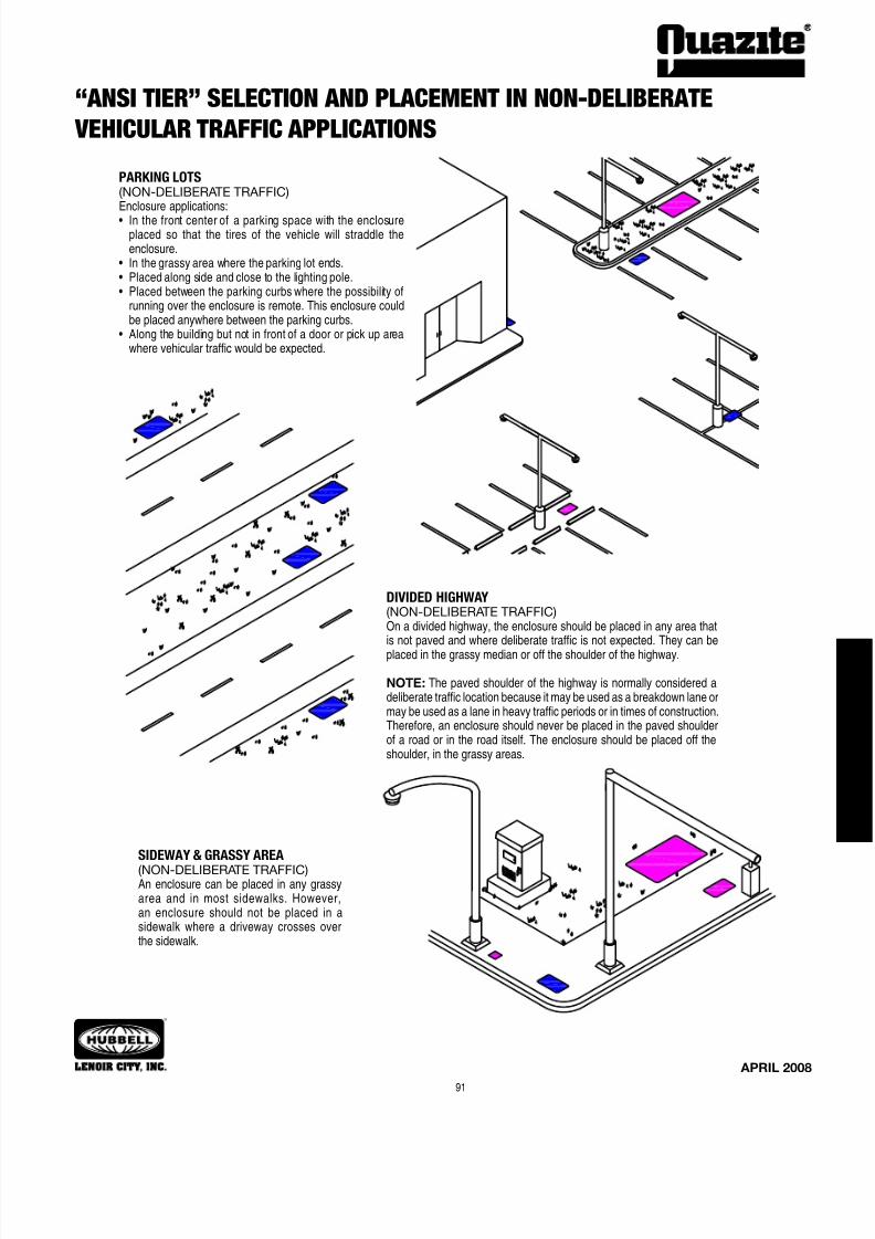
“ANSI TIER” SELECTION AND PLACEMENT IN NON-DELIBERATE
VEHICULAR TRAFFIC APPLICATIONS
rESIdEntIAL(NON-DELIBERATE TRAFFIC)Enclosures can be placed in grassy areas orsidewalks. They may also be placed in areasnext to the structures or poles where it isunlikely a vehicle will run over the enclosure.Enclosures should not be placed in thestreet or driveway where deliberate trac isanticipated.
trASh rEcEptAcLE AppLIcAtIon(NON-DELIBERATE TRAFFIC)In an area where a trash receptacle is placed, the enclosure should beplaced away rom the concrete that the receptacle is set on so that thereceptacle will not be placed on the enclosure or the wheels o the truckwill not roll over the enclosure. Even though the trac expected on the
concrete apron or in ront o the receptacle is occasional, it is deliberatebecause the trac is both intentional and heavy in nature.
duAL LAnE ALLEY
(NON-DELIBERATE TRAFFIC)In a single lane alleyway (at right), the enclosure should beplaced in the center o the alleyway. The placement minimizes thepossibility o the enclosure being run over. In a dual lane alleyway,the enclosure should be placed as close to the building as possible.Most o the time, two vehicles will not be in the alleyway at thesame time, so the chances o the enclosure getting run over will beminimal. Knowledge o the location and expected trac patternsshould be used to determine i trac would be deliberate or non-deliberate as dened previously.
The enclosures shown in thesesketches have been color coded
to indicate the proper Tier levelrequired for the application.
Green = Pedestrian/Tier 5Magenta = Tier 8Blue = Tier 15 or 22
“ANSI TIER” SELECTION AND PLACEMENT IN NON-DELIBERATE
VEHICULAR TRAFFIC APPLICATIONS
SIdEWAY & grASSY ArEA
(NON-DELIBERATE TRAFFIC)An enclosure can be placed in any grassyarea and in most sidewalks. However,an enclosure should not be placed in asidewalk where a driveway crosses overthe sidewalk.
running over the enclosure is remote. This enclosure couldbe placed anywhere between the parking curbs.
• Alongthebuildingbutnotinfrontofadoororpickupareawhere vehicular trac would be expected.
dIvIdEd hIghWAY(NON-DELIBERATE TRAFFIC)On a divided highway, the enclosure should be placed in any area thatis not paved and where deliberate trac is not expected. They can be
placed in the grassy median or o the shoulder o the highway.
NOTE: The paved shoulder o the highway is normally considered adeliberate trac location because it may be used as a breakdown lane ormay be used as a lane in heavy trac periods or in times o construction.Thereore, an enclosure should never be placed in the paved shouldero a road or in the road itsel. The enclosure should be placed o theshoulder, in the grassy areas.
EZ-Nut and Self-Aligning Nut Cleaning & Replacement Instructions
EZ-Nut Cleanout Procedure
1. Make certain drain hole is clear. I it is not, scrape o materialwith a fat edge and remove any visible obstruction(s). The drainhole is located approximately 2” below the bearing ledge.
2. Insert fat head screw driver into insert. Scrape dirt o othreads and clean out any excess dir t.
3. (Optional) Spray WD-40 ® or equivalent lubricant into insert tolubricate the threads and help loosen any remaining debris.
4. Replace cover and secure bolts into insert.
Self-Aligning Nut Replacement:
1. Remove screws using a phillips screwdriver. Then remove theretainer clip.
2. Remove 1/2-13 UNC square nut and replace it with a new 1/2-13 UNC square nut.
3. Replace the retainer clip and screws.
Quazite has redesigned the EZ-Nut assembly (Style “B”) to provide a 40% greater drainage opening area and enable quicker and easier nut
replacement. This Style “B” design will be included in new production, but existing inventories may have the older Style “A” EZ-Nut assembly.These instructions are provided in the event it is necessary to replace an existing nut.
*To determine which EZ-Nut design is in any box, insert a screwdriver into the drainage opening and pull upward. I the door does not popopen, the Style “A” EZ-Nut is in the box. Follow the instructions or the Style “A” design. I the door pops open, ollow the instructions or the
Style “B” EZ-Nut design.
Style “B” EZ-Nut replacement procedure*
1. Locate the drainage opening in the area containingthe insert. Insert a screwdriver into the opening at
approximately the angle shown in Figure 1.2. Ater inserting the screwdriver into the drainage
opening, pull upward on the handle o the screw-
driver in order to pry open the door o the insert asshown in Figure 2.
3. I necessary, remove any remaining debris rom theopening. Ater the opening is clear, remove existing
nut and replace with a nut o the required size.
Style “A” EZ-Nut replacement procedure*
1. Measure 13/16” down rom bearing ledge o the enclosure. Using a screwdriver andhammer, punch a hole into the cavity o the insert. Clear excess material out o the open-
ing.2. Insert a screwdriver into the top opening and push the 3/18-16 UNC square nut out o
the opening just created. Replace with a new 3/8-16 UNC square nut and plug the cavityin the sidewall i necessary.
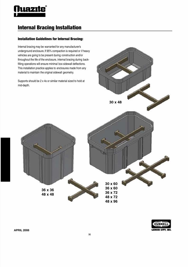
Concrete collars may be desired or installations in driveways, parking lots
and o-roadway applications where subject to occasional non-deliberatetrac. This applies to boxes made rom any material to provide addedprotection or the top lip. This is not necessary in grassy areas or areas
subject to pedestrian trac.
Notes:
1. Concrete encasement to be 3,000 psi minimum.
2. Concrete encasement collar dimension, D, to be equal todesign pavement depth.
Hubbell Lenoir City, Inc. - Lenoir City, Tennessee Hubbell Lenoir City, Inc. - San Jose, Caliornia
HUBBELL - LENOIR CITY, INC.
(Lenoir City, Tennessee; San Jose, California)
Hubbell Lenoir City, with manuacturing plants in Lenoir City, Tennessee and San Jose, Caliornia, is the nation’s largest precastero polymer concrete products. Polymer concrete, which uses polymer resin instead o Portland Cement, is a strong, lightweight, highlyimpermeable material.
Though both manuacturing plants produce precast polymer concrete products, the plants dier somewhat rom each other. The 75,000square oot San Jose location is the older o the two. “It’s really the cornerstone o our business,” explains John Downing, Vice President andGeneral Manager o Hubbell Lenoir City. In operation since the early 1970s, this plant boasts many employees with 15+ years o experience.
The San Jose plant manuactures all products in the QUAZITE ® utility enclosure and POLYCAST ® drain system product lines.
The 78,000 square oot Lenoir City acility was built in 1987 to replace smaller plants operating in Houston, Norolk and Detroit. Down-ing says an East Tennessee site was chosen or several reasons: the availability o motor reight (the plant is conveniently located near both
Interstates 40 and 75, a geographically central location that allows it to serve the entire east coast) and the availability o a good work orce.Each acility, unique in its own right, complements the other, allowing Quazite and Polycast to serve both the East and West coasts.
quAZItE® utility products, which make up the oldest and largest group, are products engi-neered or the electrical, water and gas utilities, telecommunications and transportation industries.
Underground pull/splice boxes, service boxes, handholes, box pads, and telephone and electricequipment pads are included in the QUAZITE ® line. These lightweight products are easier, andthereore less expensive, to install. QUAZITE ® ’s strength, durability and corrosion resistance
means that it will last longer, reducing lie cycle costs.
poLYcASt® presloped trench drain is used in a wide variety o applications rom airportsto major highway systems to light duty residential to industrial plants. POLYCAST ® oers easy to
install, low-cost channels, catch basins and a variety o gratings which are resistant to chemicalsand water erosion.
Polymer concrete products are manuactured at the Lenoir City Division plants in Lenoir City, TN and San Jose, CA.
Registered Proessional Engineers are on hand to assist with design,specication development and review. Full CAD capabilities are available and
can be used to electronically transmit drawings and les to you.
Sales and Customer Service
Quazite precast polymer concrete products are sold by a network ostocking distributors throughout the country. In support o the distributors
are Sales Representatives knowledgeable in the products and applications.Regional Sales Managers, as well as Product Managers, work to providecustomer service and satisaction.
Competent, riendly, customer service personnel are on sta to respondquickly to customer questions and concerns.
Special care is given by order receipt through plant scheduling, qualitycontrol and shipping to meet all needs.
Website
QUAZITE ® literature and product drawings are now conveniently avail-able through the Quazite website at www.quazite.com. For the latest revisionsand additions to our product line, visit us online at:
www.quazite.com
Research and Development
Quazite is involved in continuous research and development pro-grams. Products are reviewed, updated and improved as changes occurin the market place.
As engineers become aware o the eatures and benets o polymerconcrete, the range o applications or this unique material continues togrow.
Precast polymer concrete may be the engineering solution or prob-lems associated with traditional materials.
Quazite is committed to quality assurance, product improvement and research into new materialsand applications. Highly specialized Quality Assurance sta at each manuacturing acility ensureproduct consistency and conormance to customer specications.
Standard testing is perormed to assure the highest quality products. In addition, other customtests are perormed on a routine basis as required or the application.
Standard physical testing is perormed or compressive strength, tensile strength, and fexuralstrength. The material is tested according to the requirements o ASTM Method D-543, Section 7 or
chemical resistance.
As seen rom the examples o test procedures shown here, product development and qualityhave always been emphasized. That emphasis is more prevalent today than ever beore and will
continue to grow in the uture.
Shipping & Inventory
Many dierent types o products are shipped daily - drain, and utility service
boxes.
An extensive inventory is maintained on each product to assure that customersreceive a quick delivery.


![CASE NO. 3^-cr- ]qZ-J-2oua?](https://static.documents.pub/doc/80x56/6217f637ff47461da70bc8b1/case-no-3-cr-qz-j-2oua.jpg)


