R-23GT-F R-24GT-F In the interest of user-safety the oven should be restored to its original condition and only parts identical to those specified should be used. WARNING TO SERVICE PERSONNEL: Microwave ovens contain circuitry capable of producing very high voltage and current, contact with following parts may result in a severe, possibly fatal, electrical shock. (High Voltage Capacitor, High Voltage Power Transformer, Magnetron, High Voltage Rectifier Assembly, High Voltage Harness etc..) TABLE OF CONTENTS Page PRECAUTIONS TO BE OBSERVED BEFORE AND DURING SERVICE TO AVOID POSSIBLE EXPOSURE TO EXCESSIVE MICROWAVE ENERGY ................... INSIDE FRONT COVER BEFORE SERVICING ...................................................................................................... INSIDE FRONT COVER WARNING TO SERVICE PERSONEL .................................................................................................................. 1 MICROWAVE MEASUREMENT PROCEDURE ................................................................................................... 2 FOREWORD .......................................................................................................................................................... 3 PRODUCT SPECIFICATIONS .............................................................................................................................. 4 GENERAL INFORMATION ................................................................................................................................... 4 OPERATION .......................................................................................................................................................... 6 TROUBLE SHOOTING GUIDE/ TEST PROCEDURE ........................................................................................ 11 TOUCH CONTROL PANEL ................................................................................................................................. 21 COMPONENT REPLACEMENT AND ADJUSTMENT PROCEDURE ................................................................ 31 PICTORIAL DIAGRAM ........................................................................................................................................ 37 CONTROL PANEL CIRCUIT ............................................................................................................................... 38 PRINTED WIRING BOARD ................................................................................................................................. 40 PARTS LIST ........................................................................................................................................................ 41 PACKING AND ACCESSORIES ......................................................................................................................... 46 S0512R24GTF// R-23GT-F R-24GT-F COMMERCIAL MICROWAVE OVENS MODELS SERVICE MANUAL SHARP CORPORATION This document has been published to be used for after sales service only. The contents are subject to change without notice. 1800W/R-24GT DOUBLE QUANTITY EXPRESS DEFROST 1 11 2 12 3 13 4 14 5 15 6 16 7 17 8 18 9 19 0 20 SET CHECK SIGNAL STOP/CLEAR SELECTAPOWER START SELECTATIME R-24GT-F
Transcript
R-23GT-FR-24GT-F
In the interest of user-safety the oven should be restored to its originalcondition and only parts identical to those specified should be used.
WARNING TO SERVICE PERSONNEL: Microwave ovens containcircuitry capable of producing very high voltage and current,contact with following parts may result in a severe, possibly fatal,electrical shock. (High Voltage Capacitor, High Voltage PowerTransformer, Magnetron, High Voltage Rectifier Assembly, HighVoltage Harness etc..)
TABLE OF CONTENTSPage
PRECAUTIONS TO BE OBSERVED BEFORE AND DURING SERVICE TOAVOID POSSIBLE EXPOSURE TO EXCESSIVE MICROWAVE ENERGY ................... INSIDE FRONT COVERBEFORE SERVICING ...................................................................................................... INSIDE FRONT COVERWARNING TO SERVICE PERSONEL .................................................................................................................. 1MICROWAVE MEASUREMENT PROCEDURE ................................................................................................... 2FOREWORD .......................................................................................................................................................... 3PRODUCT SPECIFICATIONS .............................................................................................................................. 4GENERAL INFORMATION ................................................................................................................................... 4OPERATION .......................................................................................................................................................... 6TROUBLE SHOOTING GUIDE/ TEST PROCEDURE ........................................................................................ 11TOUCH CONTROL PANEL ................................................................................................................................. 21COMPONENT REPLACEMENT AND ADJUSTMENT PROCEDURE ................................................................ 31PICTORIAL DIAGRAM ........................................................................................................................................ 37CONTROL PANEL CIRCUIT ............................................................................................................................... 38PRINTED WIRING BOARD ................................................................................................................................. 40PARTS LIST ........................................................................................................................................................ 41PACKING AND ACCESSORIES ......................................................................................................................... 46
S0512R24GTF//
R-23GT-FR-24GT-F
COMMERCIALMICROWAVE OVENS
MODELS
SERVICE MANUAL
SHARP CORPORATIONThis document has been published to be used for aftersales service only.The contents are subject to change without notice.
1800W/R-24GT
DOUBLEQUANTITY
EXPRESSDEFROST
111
212
313
414
515
616
717
818
919
020
SET CHECK SIGNAL
STOP/CLEARSELECTAPOWER START
SELECTATIME
R-24GT-F
R-23GT-FR-24GT-F
PRECAUTIONS TO BE OBSERVED BEFORE ANDDURING SERVICING TO AVOID POSSIBLEEXPOSURE TO EXCESSIVE MICROWAVEENERGY(a) Do not operate or allow the oven to be operated with the door open.(b) Make the following safety checks on all ovens to be serviced before activating the magnetron or other
microwave source, and make repairs as necessary: (1) interlock operation, (2) proper door closing, (3)seal and sealing surfaces (arcing, wear, and other damage), (4) damage to or loosening of hinges andlatches, (5) evidence of dropping or abuse.
(c) Before turning on microwave power for any service test or inspection within the microwave generatingcompartments, check the magnetron, wave guide or transmission line, and cavity for proper alignment,integrity, and connections.
(d) Any defective or misadjusted components in the interlock, monitor, door seal, and microwavegeneration and transmission systems shall be repaired, replaced, or adjusted by procedures describedin this manual before the oven is released to the owner.
(e) A microwave leakage check to verify compliance with the Federal Performance Standard should beperformed on each oven prior to release to the owner.
BEFORE SERVICINGBefore servicing an operative unit, perform a microwave emission check as per the MicrowaveMeasurement Procedure outlined in this service manual.If microwave emissions level is in excess of the specified limit, contact SHARP ELECTRONICSCORPORATION immediately @1-800-237-4277.
If the unit operates with the door open, service person should 1) tell the user not to operate the ovenand 2) contact SHARP ELECTRONICS CORPORATION and the Food and Drug Administration'sCenter for Devices and Radiological Health immediately.
Service personnel should inform SHARP ELECTRONICS CORPORATION of any certified unit foundwith emissions in excess of 4mW/cm2. The owner of the unit should be instructed not to use the unituntil the oven has been brought into compliance.
R-23GT-FR-24GT-F
1
WARNING TO SERVICE PERSONNEL
Microwave ovens contain circuitry capable of pro-ducing very high voltage and current, contact withfollowing parts may result in a severe, possiblyfatal, electrical shock.(Example)High Voltage Capacitor, High Voltage Power Trans-former, Magnetron, High Voltage Rectifier Assem-bly, High Voltage Harness etc..Read the Service Manual carefully and follow allinstructions.
Before Servicing
1. Disconnect the power supply cord , and then removeouter case.
2. Open the door and block it open.3. Discharge two high voltage capacitors.
WARNING: RISK OF ELECTRIC SHOCK.DISCHARGE THE TWO HIGHVOLTAGE CAPACITORS BEFORESERVICING.
The high-voltage capacitors remain charged about 60 sec-onds after the oven has been switched off. Wait for 60seconds and then short-circuit the connection of the high-voltage capacitors (that are the connecting lead of the high-voltage rectifiers) against the chassis with the use of aninsulated screwdriver.
Whenever troubleshooting is performed the power supplymust be disconnected. It may, in some cases, be necessary toconnect the power supply after the outer case has beenremoved, in this event,1. Disconnect the power supply cord, and then remove outer
case.2. Open the door and block it open.3. Discharge two high voltage capacitors.4. Disconnect the leads to the primary of the power transformer.5. Ensure that the leads remain isolated from other components
and oven chassis by using insulation tape.6. After that procedure, reconnect the power supply cord.
When the testing is completed,1. Disconnect the power supply cord, and then remove outer
case.2. Open the door and block it open.3. Discharge two high voltage capacitors.4. Reconnect the leads to the primary of the power transformer.5. Reinstall the outer case (cabinet).6. Reconnect the power supply cord after the outer case is
installed.7. Run the oven and check all functions.
After repairing
1. Reconnect all leads removed from components duringtesting.
2. Reinstall the outer case (cabinet).3. Reconnect the power supply cord after the outer case is
installed.4. Run the oven and check all functions.
Microwave ovens should not be run empty. To test for thepresence of microwave energy within a cavity, place a cup ofcold water on the oven turntable, close the door and set thepower to HIGH and set the microwave timer for two (2) minutes.When the two minutes has elapsed (timer at zero) carefullycheck that the water is now hot. If the water remains cold carryout Before Servicing procedure and re-examine the connec-tions to the component being tested.
When all service work is completed and the oven is fullyassembled, the microwave power output should be checkedand microwave leakage test should be carried out.
Don't Touch !Danger High Voltage
R-23GT-FR-24GT-F
2
MICROWAVE MEASUREMENT PROCEDURE
A. Requirements:
1) Microwave leakage limit (Power density limit): The power density of microwave radiation emitted by a microwave oven shouldnot exceed 1mW/cm2 at any point 5cm or more from the external surface of the oven, measured prior to acquisition by apurchaser, and thereafter (through the useful life of the oven), 5 mW/cm2 at any point 5cm or more from the external surfaceof the oven.
2) Safety interlock switches: Primary interlock relay and door sensing switch shall prevent microwave radiation emission in excessof the requirement as above mentioned, secondary interlock switch shall prevent microwave radiation emission in excess of5 mW/cm2 at any point 5cm or more from the external surface of the oven.
B. Preparation for testing:Before beginning the actual measurement of leakage, proceed as follows:1) Make sure that the actual instrument is operating normally as specified in its instruction booklet.
Important:Survey instruments that comply with the requirement for instrumentation as prescribed by the performance standard formicrowave ovens, 21 CFR 1030.10(c)(3)(i), must be used for testing.
2) Place the oven tray in the oven cavity.3) Place the load of 275±15 ml (9.8 oz) of tap water initially at 20±5˚C (68˚F) in the center of the oven cavity.
The water container shall be a low form of 600 ml (20 oz) beaker with an inside diameter of approx. 8.5 cm (3-1/2 in.) and madeof an electrically nonconductive material such as glass or plastic.The placing of this standard load in the oven is important not only to protect the oven, but also to insure that any leakage ismeasured accurately.
4) Set the cooking control on Full Power Cooking Mode5) Close the door and select a cook cycle of several minutes. If the water begins to boil before the survey is completed, replace
it with 275 ml of cool water.
C. Leakage test:
Closed-door leakage test (microwave measurement)1) Grasp the probe of the survey instrument and hold it perpendicular to the gap between the door and the body of the oven.2) Move the probe slowly, not faster than 1 in./sec. (2.5 cm/sec.) along the gap, watching for the maximum indication on the meter.3) Check for leakage at the door screen, sheet metal seams and other accessible positions where the continuity of the metal has
been breached (eg., around the switches, indicator, and vents).While testing for leakage around the door pull the door away from the front of the oven as far as is permitted by the closed latchassembly.
4) Measure carefully at the point of highest leakage and make sure that the highest leakage is no greater than 4mW/cm2, and thatthe secondary interlock switch does turn the oven OFF before any door movement.
NOTE: After servicing, record data on service invoice and microwave leakage report.
R-23GT-FR-24GT-F
3
SHARP ELECTRONICS CORPORATION
SHARP PLAZA, MAHWAH,NEW JERSEY 07430-2135
SERVICE MANUAL
COMMERCIALMICROWAVE OVEN
R-23GT-F/ R-24GT-F
FOREWORD
This Manual has been prepared to provide Sharp Electronics Corp.Service Personnel with Operation and Service Information for the SHARPMICROWAVE OVENS, R-23GT-F/ R-24GT-F.
It is recommended that service personnel carefully study the entire text ofthis manual so that they will be qualified to render satisfactory customerservice.
Check the interlock switches and the door seal carefully. Special attentionshould be given to avoid electrical shock and microwave radiation hazard.
WARNINGNever operate the oven until the following points are ensured.(A) The door is tightly closed.(B) The door brackets and hinges are not defective.(C) The door packing is not damaged.(D) The door is not deformed or warped.(E) There is no other visible damage with the oven.
Servicing and repair work must be carried out only by trained servicepersonnel.
DANGERCertain initial parts are intentionally not grounded and presenta risk of electrical shock only during servicing. Service person-nel - Do not contact the following parts while the appliance isenergized;High Voltage Capacitor, Power Transformer, Magnetron, HighVoltage Rectifier Assembly, High Voltage Harness;If provided, Vent Hood, Fan assembly, Cooling Fan Motor.
All the parts marked “*” on parts list are used at voltages more than250V.
Removal of the outer wrap gives access to voltage above 250V.
All the parts marked “∆” on parts list may cause undue microwaveexposure, by themselves, or when they are damaged, loosened orremoved.
PRODUCT DESCRIPTION
GENERAL INFORMATION
OPERATION
TROUBLESHOOTING GUIDE ANDTEST PROCEDURE
TOUCH CONTROL PANEL
COMPONENT REPLACEMENTAND ADJUSTMENT PROCEDURE
WIRING DIAGRAM
PARTS LIST
R-23GT-FR-24GT-F
4
ITEM DESCRIPTIONPower Requirements R-23GT-F: 230/208 Volts 2.5 kW Approx. 13.3 A at 208 V / Approx. 11.9 A at 230 V
R-24GT-F: 230/208 Volts 2.9 kW Approx. 14.6 A at 208 V / Approx. 13.1 A at 230 V60 Hertz / Single phase, 3 wire grounded
Power Output R-23GT-F: 1600 watts
R-24GT-F: 1800 watts (IEC 705 Test Procedure) Operating frequency of 2450MHz
Control Complement Touch Control SystemDigital Display10 Number Pads
STOP/CLEAR pad
START pad
SELECTAPOWER pad (Power level: 0 to 100%)
SELECTATIME pad
DOUBLE QUANTITY pad
EXPRESS DEFROST pad
Memory SET pad
Memory CHECK pad
SIGNAL pad
Weight R-23GT-F: Approx. 63 lbs (29 kg ) R-24GT-F: Approx. 65 lbs (30 kg)
Safety Standard UL Listed FCC AuthorizedDHHS Rules, CFR, Title 21, Chapter 1, Subchapter JNSF Certified
SPECIFICATION
GENERAL INFORMATION
GROUNDING INSTRUCTIONS
This appliance must be grounded. In the event of an electrical short circuit, grounding reduces the risk of electric shock by providingan escape wire for the electric current. This appliance is equipped with a cord having a grounding wire with a grounding plug. Theplug must be plugged into an outlet that is properly installed and grounded.
WARNING: Improper use of the grounding plug can result in a risk of electric shock. The electrical requirements are 230/208 Volt,60 Hz, AC only, 15 Amp or more (R-23GT-F) and 20 Amp or more (R-24GT-F) fused electrical supply. It isrecommended that a separate circuit serving only this appliance be provided. When installing this appliance, observeall applicable codes and ordinances. If it is necessary to use an extension cord, use only a 3-wire extension cord thathas a 3-blade grounding plug and a 3-slot receptacle that will accept the plug on the appliance. The marked ratingof the extension cord should be AC 230/208 Volt 15 Amp (R-23GT-F) and 20 Amp (R-24GT-F).
Receptacle Box Cover
3-Pronged plug(6-20P)
3-Pronged, Receptacle(6-20R)
Receptacle Box Cover
3-Pronged plug(6-20P)
3-Pronged, Receptacle(6-15R)
230/208V 15AR-23GT-F
230/208V 20AR-24GT-F
R-23GT-FR-24GT-F
5
OVEN DIAGRAM
Power supply cord
230 V230 V 208 V
208 V
(A)
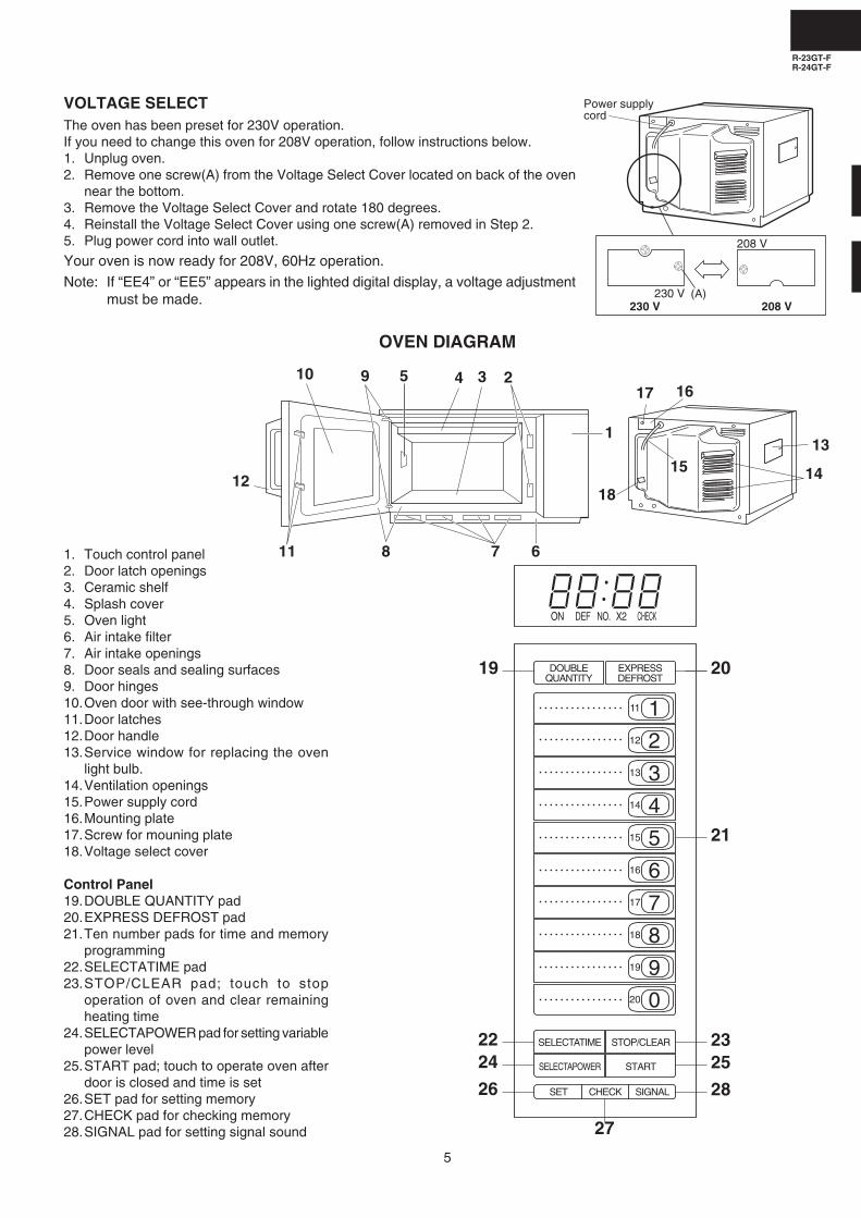
1. Touch control panel2. Door latch openings3. Ceramic shelf4. Splash cover5. Oven light6. Air intake filter7. Air intake openings8. Door seals and sealing surfaces9. Door hinges10.Oven door with see-through window11.Door latches12.Door handle13.Service window for replacing the oven
Control Panel19.DOUBLE QUANTITY pad20.EXPRESS DEFROST pad21.Ten number pads for time and memory
programming22.SELECTATIME pad23.STOP/CLEAR pad; touch to stop
operation of oven and clear remainingheating time
24.SELECTAPOWER pad for setting variablepower level
25.START pad; touch to operate oven afterdoor is closed and time is set
26.SET pad for setting memory27.CHECK pad for checking memory28.SIGNAL pad for setting signal sound
4
1
5 29 3
678
10
11
1215 14
13
1617
18
DOUBLEQUANTITY
EXPRESSDEFROST
111
212
313
414
515
616
717
818
919
020
SELECTATIME STOP/CLEAR
SELECTAPOWER START
SET CHECK SIGNAL
DEFON NO. X2 CHECK
20
21
2325
2826
2422
19
27
VOLTAGE SELECTThe oven has been preset for 230V operation.If you need to change this oven for 208V operation, follow instructions below.1. Unplug oven.2. Remove one screw(A) from the Voltage Select Cover located on back of the oven
near the bottom.3. Remove the Voltage Select Cover and rotate 180 degrees.4. Reinstall the Voltage Select Cover using one screw(A) removed in Step 2.5. Plug power cord into wall outlet.
Your oven is now ready for 208V, 60Hz operation.
Note: If “EE4” or “EE5” appears in the lighted digital display, a voltage adjustmentmust be made.
R-23GT-FR-24GT-F
6
OPERATION
DESCRIPTION OF OPERATING SEQUENCE
The following is a description of component functions duringoven operation.
OFF CONDITIONClosing the door activates the door sensing switch and second-ary interlock switches (1), (2). (In this condition, the monitorswitches (1) & (2) contacts are opened.) When the oven isplugged in, and the rated voltage is supplied to the control unitthrough the noise filter, (figure O-1), the display will show " .".
IDLE CONDITIONWhen the door is opened, the contacts of the door sensingswitch open, initiating the following:1. A signal is input to the control unit energizing the coil of shut-
off relay (RY-1).2. The shut-off relay (RY-1) contacts close completing circuits
to turn on the oven lamp, blower motor and stirrer motors.3. If the door remains open, 60 seconds later the control unit
de-energizes shut-off relay (RY-1) turning off the ovenlamp, blower motor and stirrer motors.
When the door is closed, the door sensing switch contactsclose. With the closing of the door sensing switch contacts, anadditional circuit is provided which will permit the operation ofthe oven when one of the touch pads is depressed. Since thecontrol is enabled through the door sensing switch, the doormust be closed before the touch pads will be effective. Whenthe door is closed, a full 60 second IDLE condition is alwaysprovided for selecting and pressing the desired touch pads. A60 second IDLE condition will also follow the end of each cookcycle.
COOKING CONDITIONWhen the door is closed from the open position and Memorypad is touched the, following will occur:
1. The contacts of relays are closed and components connectedto the relays are turned on (For details, refer to Figure O-3)
2. Rated voltage is supplied to the primary winding of thepower transformer and is converted to about 3.1 voltsoutput on the filament winding, and approximately 2040volts on the high voltage winding.
3. The filament winding voltage heats the magnetron filamentand the H.V. winding voltage is sent to a voltage doublercircuit.
4. The microwave energy produced by the magnetron ischannelled through the waveguide into the cavity feed-box,and then into the cavity where the food is placed to becooked.
5. Upon completion of the cooking time, the oven will revert tothe IDLE condition.
6. When the door is opened during a cook cycle, monitorswitches (1) & (2), door sensing switch, secondary interlockswitches (1), (2) and primary interlock relays (1), (2) areactivated with the following results. The circuits to the highvoltage components are de-energized, and the digital read-out displays " . " and cooking is cancelled (in the case ofMemory cooking).
7. The monitor switch (1) is electrically monitoring the operationof the secondary interlock switch (1) and primary interlockrelay (1), and monitor switch (2) is electrically monitoring theoperation of the secondary interlock switch (2) and primaryinterlock relay (2), and monitor switches (1), (2) aremechanically associated with the door so that it will functionin the following sequence.
(1) When the door opens from a closed position, the contactsof the primary interlock relays (1), (2) and secondaryinterlock switches (1), (2) open. Then the monitor switchcontacts close.
(2) When the door is closed from the open position, the monitorswitches (1), (2) contacts first open, and then the contactsof the secondary interlock switches (1), (2) close.
If the secondary interlock switches (1), (2) and primary interlockrelays (1), (2) fail with their contacts closed when the door isopened, the closing of the monitor switches (1), (2) contacts willform a short circuit through the monitor fuse, secondary inter-lock switches (1), (2) and primary interlock relays (1), (2),causing the monitor fuse to blow.
VARIABLE POWER COOKINGWhen Variable Cooking Power is programmed, the ratedvoltage A.C. is supplied to the power transformer intermittentlythrough the contacts of relay (RY-2, RY-3). Relays RY-2 andRY-3 are operated by the control unit within an interval secondtime base. Microwave power operation is as follows:
POWER LEVEL ON TIME OFF TIME
100% 32 sec. 0 sec.
90% 30 sec. 2 sec.
80 % 26 sec. 6 sec.
70% 24 sec. 8 sec.
60% 22 sec. 10 sec.
50% 18 sec. 14 sec.
40% 16 sec. 16 sec.
30% 12 sec. 20 sec.
20% 8 sec. 24 sec.
10% 6 sec. 26 sec.
0% 0 sec. 32 sec.
Note: The ON/OFF time ratio does not exactly correspondwith the percentage of microwave power, becauseapprox. 2 seconds are needed for heating of themagnetron filament.
R-23GT-FR-24GT-F
7
TWO MAGNETRON OPERATION SYSTEMTwo magnetrons (1), (2) are equipped in order to get highermicrowave power output. The primary windings of the powertransformers (1), (2) are connected so that each magnetroncan be oscillated alternatively according to the frequency of thepower supply. Refer to the Figure B-1.
Figure B-1. Operation of Magnetron
COMMERCIALFREQUENCY(60HZ)
POWER OUTPUTBY MAGNETRON 1
POWER OUTPUTBY MAGNETRON 2
OPERATION OFMAGNETRON
Figure O-1. Oven Schematic-OFF Condition (208 V Condition)
SCHEMATIC
NOTE: CONDITION OF OVEN
1. DOOR CLOSED OR 1 MINUTE AFTER COOK OFF2. " . " APPEARS ON DISPLAY
OV
EN
LA
MP
BLO
WE
R M
OT
OR
208/
230V
60H
z
MA
GN
ET
RO
N (
1)
BM
ST
IRR
ER
MO
TO
R
SM
SM
H3
H1
MA
GN
ET
RO
N T
HE
RM
IST
OR
BLK
WH
T
DOOR SENSINGSWITCH
A1 A3 B2 B1
A7
RY
2TA
B1
TA
B2
RY
3
OVEN TEMP.FUSE
B3
OV
EN
TH
ER
MIS
TO
R (
1)
OV
EN
TH
ER
MIS
TO
R (
2)
PRIMARYINTERLOCKRELAY (1)
PRIMARYINTERLOCKRELAY (2)
MO
NIT
OR
SW
ITC
H (
2)
MO
NIT
OR
SW
ITC
H (
1)
POWERTRANSFORMER (1)
CAPACITOR (1)0.94µF
CAPACITOR (2)0.94µF
POWERTRANSFORMER (2)
H.V
. RE
CT
IFIE
R (
1)H
.V. R
EC
TIF
IER
(2)
MA
GN
ET
RO
N (
2)
RY
1
A5
OL
COM
GRN
NCV.S.SW (1)
COM
NC
NC
COM
V.S
.SW
(3)
VO
LTA
GE
SE
LEC
T
SW
ITC
H (
V.S
.SW
) (2
)
SECONDARY INTERLOCKSWITCHE(1)
SECONDARY INTERLOCKSWITCHE(2)
OL
MAGNETRONTEMP. FUSE (1)
MAGNETRONTEMP. FUSE (2)
FUSE 20A
DIS
CH
AR
GE
RE
SIS
TO
R 470K
1/2
W
LIN
E C
RO
SS
CA
PA
CIT
OR
1.0
F A
C250V
NO
ISE
SU
PP
RE
SS
ION
CO
IL
3300pF
3300pF
NOISE FILTER
R-23GT-FR-24GT-F
8
SCHEMATIC
NOTE: CONDITION OF OVEN
1. FOR 1MINUTE AFTER DOOR OPENED.2. " . " APPEARS ON DISPLAY.
Figure O-2. Oven Schematic-IDLE Condition (208 V Condition)
SCHEMATIC
NOTE: CONDITION OF OVEN
1. DOOR CLOSED.2. SELECTATIME PAD TOUCHED.3. COOKING TIME PROGRAMMED.4. START PAD TOUCHED.
Figure O-3. Schematic-Cooking Condition (208 V Condition)
OV
EN
LA
MP
BLO
WE
R M
OT
OR
208/
230V
60H
z
MA
GN
ET
RO
N (
1)
BM
ST
IRR
ER
MO
TO
R
SM
SM
H3
H1
MA
GN
ET
RO
N T
HE
RM
IST
OR
BLK
WH
T
DOOR SENSINGSWITCH
A1 A3 B2 B1
A7
RY
2TA
B1
TA
B2
RY
3
OVEN TEMP.FUSE
B3
OV
EN
TH
ER
MIS
TO
R (
1)
OV
EN
TH
ER
MIS
TO
R (
2)
PRIMARYINTERLOCKRELAY (1)
PRIMARYINTERLOCKRELAY (2)
MO
NIT
OR
SW
ITC
H (
2)
MO
NIT
OR
SW
ITC
H (
1)
POWERTRANSFORMER (1)
CAPACITOR (1)0.94µF
CAPACITOR (2)0.94µF
POWERTRANSFORMER (2)
H.V
. RE
CT
IFIE
R (
1)H
.V. R
EC
TIF
IER
(2)
MA
GN
ET
RO
N (
2)
RY
1
A5
OL
COM
GRN
NCV.S.SW (1)
COM
NC
NC
COM
V.S
.SW
(3)
VO
LTA
GE
SE
LEC
T
SW
ITC
H (
V.S
.SW
) (2
)
SECONDARY INTERLOCKSWITCHE(1)
SECONDARY INTERLOCKSWITCHE(2)
OL
MAGNETRONTEMP. FUSE (1)
MAGNETRONTEMP. FUSE (2)
FUSE 20A
DIS
CH
AR
GE
RE
SIS
TO
R 470K
1/2
W
LIN
E C
RO
SS
CA
PA
CIT
OR
1.0
F A
C250V
NO
ISE
SU
PP
RE
SS
ION
CO
IL
3300pF
3300pF
NOISE FILTER
OV
EN
LA
MP
BLO
WE
R M
OT
OR
208/
230V
60H
z
MA
GN
ET
RO
N (
1)
BM
ST
IRR
ER
MO
TO
R
SM
SM
H3
H1
MA
GN
ET
RO
N T
HE
RM
IST
OR
BLK
WH
T
DOOR SENSINGSWITCH
A1 A3 B2 B1
A7
RY
2TA
B1
TA
B2
RY
3
OVEN TEMP.FUSE
B3
OV
EN
TH
ER
MIS
TO
R (
1)
OV
EN
TH
ER
MIS
TO
R (
2)
PRIMARYINTERLOCKRELAY (1)
PRIMARYINTERLOCKRELAY (2)
MO
NIT
OR
SW
ITC
H (
2)
MO
NIT
OR
SW
ITC
H (
1)
POWERTRANSFORMER (1)
CAPACITOR (1)0.94µF
CAPACITOR (2)0.94µF
POWERTRANSFORMER (2)
H.V
. RE
CT
IFIE
R (
1)H
.V. R
EC
TIF
IER
(2)
MA
GN
ET
RO
N (
2)
RY
1
A5
OL
COM
GRN
NCV.S.SW (1)
COM
NC
NC
COM
V.S
.SW
(3)
VO
LTA
GE
SE
LEC
T
SW
ITC
H (
V.S
.SW
) (2
)
SECONDARY INTERLOCKSWITCHE(1)
SECONDARY INTERLOCKSWITCHE(2)
OL
MAGNETRONTEMP. FUSE (1)
MAGNETRONTEMP. FUSE (2)
FUSE 20A
DIS
CH
AR
GE
RE
SIS
TO
R 470K
1/2
W
LIN
E C
RO
SS
CA
PA
CIT
OR
1.0
F A
C250V
NO
ISE
SU
PP
RE
SS
ION
CO
IL
3300pF
3300pF
NOISE FILTER
R-23GT-FR-24GT-F
9
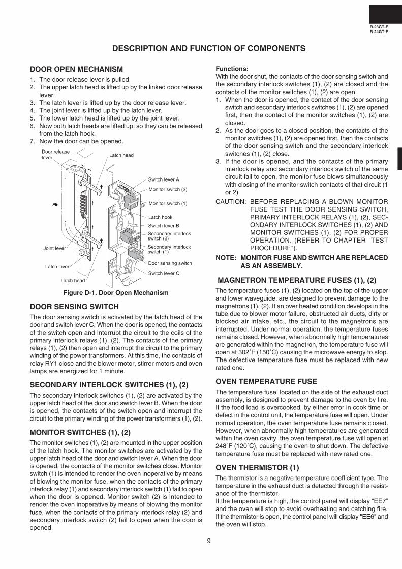
DOOR OPEN MECHANISM1. The door release lever is pulled.2. The upper latch head is lifted up by the linked door release
lever.3. The latch lever is lifted up by the door release lever.4. The joint lever is lifted up by the latch lever.5. The lower latch head is lifted up by the joint lever.6. Now both latch heads are lifted up, so they can be released
from the latch hook.7. Now the door can be opened.
Figure D-1. Door Open Mechanism
DOOR SENSING SWITCHThe door sensing switch is activated by the latch head of thedoor and switch lever C. When the door is opened, the contactsof the switch open and interrupt the circuit to the coils of theprimary interlock relays (1), (2). The contacts of the primaryrelays (1), (2) then open and interrupt the circuit to the primarywinding of the power transformers. At this time, the contacts ofrelay RY1 close and the blower motor, stirrer motors and ovenlamps are energized for 1 minute.
SECONDARY INTERLOCK SWITCHES (1), (2)The secondary interlock switches (1), (2) are activated by theupper latch head of the door and switch lever B. When the dooris opened, the contacts of the switch open and interrupt thecircuit to the primary winding of the power transformers (1), (2).
MONITOR SWITCHES (1), (2)The monitor switches (1), (2) are mounted in the upper positionof the latch hook. The monitor switches are activated by theupper latch head of the door and switch lever A. When the dooris opened, the contacts of the monitor switches close. Monitorswitch (1) is intended to render the oven inoperative by meansof blowing the monitor fuse, when the contacts of the primaryinterlock relay (1) and secondary interlock switch (1) fail to openwhen the door is opened. Monitor switch (2) is intended torender the oven inoperative by means of blowing the monitorfuse, when the contacts of the primary interlock relay (2) andsecondary interlock switch (2) fail to open when the door isopened.
DESCRIPTION AND FUNCTION OF COMPONENTS
Functions:With the door shut, the contacts of the door sensing switch andthe secondary interlock switches (1), (2) are closed and thecontacts of the monitor switches (1), (2) are open.1. When the door is opened, the contact of the door sensing
switch and secondary interlock switches (1), (2) are openedfirst, then the contact of the monitor switches (1), (2) areclosed.
2. As the door goes to a closed position, the contacts of themonitor switches (1), (2) are opened first, then the contactsof the door sensing switch and the secondary interlockswitches (1), (2) close.
3. If the door is opened, and the contacts of the primaryinterlock relay and secondary interlock switch of the samecircuit fail to open, the monitor fuse blows simultaneouslywith closing of the monitor switch contacts of that circuit (1or 2).
CAUTION: BEFORE REPLACING A BLOWN MONITORFUSE TEST THE DOOR SENSING SWITCH,PRIMARY INTERLOCK RELAYS (1), (2), SEC-ONDARY INTERLOCK SWITCHES (1), (2) ANDMONITOR SWITCHES (1), (2) FOR PROPEROPERATION. (REFER TO CHAPTER "TESTPROCEDURE").
NOTE: MONITOR FUSE AND SWITCH ARE REPLACEDAS AN ASSEMBLY.
MAGNETRON TEMPERATURE FUSES (1), (2)The temperature fuses (1), (2) located on the top of the upperand lower waveguide, are designed to prevent damage to themagnetrons (1), (2). If an over heated condition develops in thetube due to blower motor failure, obstructed air ducts, dirty orblocked air intake, etc., the circuit to the magnetrons areinterrupted. Under normal operation, the temperature fusesremains closed. However, when abnormally high temperaturesare generated within the magnetron, the temperature fuse willopen at 302˚F (150˚C) causing the microwave energy to stop.The defective temperature fuse must be replaced with newrated one.
OVEN TEMPERATURE FUSEThe temperature fuse, located on the side of the exhaust ductassembly, is designed to prevent damage to the oven by fire.If the food load is overcooked, by either error in cook time ordefect in the control unit, the temperature fuse will open. Undernormal operation, the oven temperature fuse remains closed.However, when abnormally high temperatures are generatedwithin the oven cavity, the oven temperature fuse will open at248˚F (120˚C), causing the oven to shut down. The defectivetemperature fuse must be replaced with new rated one.
OVEN THERMISTOR (1)The thermistor is a negative temperature coefficient type. Thetemperature in the exhaust duct is detected through the resist-ance of the thermistor.If the temperature is high, the control panel will display “EE7”and the oven will stop to avoid overheating and catching fire.If the thermistor is open, the control panel will display "EE6" andthe oven will stop.
Latch head
Monitor switch (1)
Latch hook
Secondary interlock switch (2)
Door sensing switch
Latch head
Joint lever
Door releaselever
Latch lever
Secondary interlock switch (1)
Monitor switch (2)
Switch lever C
Switch lever A
Switch lever B
R-23GT-FR-24GT-F
10
OVEN THERMISTOR (2)This thermistor detects temperature of the oven cavity bottomplate. The thermistor is a negative temperature coefficient type.The temperature is detected through the resistance of thethermistor.If the temperature is high, the control will display “EE17” and theoven will stop.
MAGNETRON THERMISTORThe thermistor is a negative temperature coefficient type. Theair temperature around the upper magnetron is detected throughthe resistance of the thermistor.If the temperature is high, the control panel will display "EE17"and the oven will stop to protect the lower magnetron againstoverheat.If the oven thermistor (2) and the magnetron thermistor areopen at the same time, the control panel will display "EE16" andthe oven will stop.
BLOWER MOTORThe blower motor drives a blade which draws external cool airinto the oven. This cool air is directed through the air vanessurrounding the magnetrons and cools the magnetrons. Thisair is channelled through the oven cavity to remove steam andvapours given off from the heating foods. It is then exhaustedthrough the exhausting air vents at the oven cavity.
STIRRER MOTORSThe upper and lower stirrer motors drive stirrer antennas to stirthe microwave radiation from the upper and lower waveguides.
OVEN LAMPSThe oven cavity light illuminates the interior of the oven so thatfood being cooked can be examined visually through the doorwindow without having to open the door. The oven lamp is onduring the cooking cycle and idle condition.
SELECT SWITCHES (1) - (3)The select switch assembly is an array of three separateswitches which may be configured for either 208V or 230Voperation (see General Information section, voltage select).These switches are connected to the windings of componentsspecified in the table below and make those componentscompatible with the specified line voltage by changing theirinternal windings. For 208V operation contacts (Normal Open)of the all switches are open.
SELECT SWITCH AND ELECTRICAL COMPONENTS
CONDITION
SWITCH NO. ELECTRICAL PARTS
(1) Touch control unit
(2) Power transformer (1) (Front side)
(3) Power transformer (2) (Rear side)
Oven in the 208V setting: contacts between common andnormally open are closed.
Oven in the 230V setting: contacts between common andnormally closed are closed.
NOISE FILTERThe noise filter prevents the radio frequency interference thatmight flow back in the power circuit.
Select switch (1)
Select switch (2)
Select switch (3)
COM.
N.C. N.O Select switch angle
Switch spacer
ScrewOvencavityRear
cabinetside
R-23GT-FR-24GT-F
11
TROUBLESHOOTING GUIDE
Never touch any part in the circuit with your hand or an uninsulated tool while the power supply is connected.
When troubleshooting the microwave oven, it is helpful to follow the Sequence of Operation in performing the checks. Manyof the possible causes of trouble will require that a specific test be performed. These tests are given a procedure letter whichwill be found in the "Test Procedure "section.
IMPORTANT: If the oven becomes inoperative because of a blown monitor fuse, check the monitor switches (1), (2), primaryinterlock relays RY2, RY3, door sensing switch and secondary interlock switches (1), (2), before replacing themonitor fuse. If monitor fuse is replaced, the monitor switch (1) and/or (2) must also be replaced. Use part FFS-BA033WRKZ as an assembly.
IMPORTANT: Whenever troubleshooting is performed with the power supply cord disconnected. It may, in some cases, benecessary to connect the power supply cord after the outer case has been removed, in this event,1. Disconnect the power supply cord, and then remove outer case.2. Open the door and block it open.3. Discharge two high voltage capacitors.4. Disconnect the leads to the primaries of the two power transformers.5. Ensure that the leads remain isolated from other components and oven chassis by using insulation tape.6. After that procedure, reconnect the power supply cord.
When the testing is completed1. Disconnect the power supply cord, and then remove outer case.2. Open the door and block it open.3. Discharge two high voltage capacitors.4. Reconnect the all leads removed from components during testing.5. Reinstall the outer case (cabinet).6. Reconnect the power supply cord after the outer case is installed.7. Run the oven and check all functions.
R-23GT-FR-24GT-F
12
CK
= C
heck
/ R
ST
= R
eset
/ R
E =
Rep
lace
Hom
e fu
se
blow
s w
hen
pow
er
cord
is
pl
ugge
d in
to
wal
l re
cept
acle
Mon
itor
fuse
blo
ws
whe
n po
wer
cor
d is
plu
gged
int
o w
all
rece
ptac
le.
" .
"
does
not
app
ear
in d
ispl
ay w
hen
pow
er c
ord
is f
irst
plug
ged
into
wal
l rec
epta
cle.
Blo
wer
mot
or d
oes
not
oper
ate.
(O
ven
lam
p(s)
and
stir
rer
mot
ors
go o
n fo
r 1
min
ute
afte
r do
or is
ope
ned.
)B
low
er m
otor
, ov
en la
mp(
s) a
nd s
tirre
r m
otor
s do
not
go
on f
or
1 m
inut
e af
ter
door
is o
pene
d.B
low
er m
otor
and
stir
rer
mot
ors
go o
n bu
t ov
en la
mp(
s) d
o no
t lig
ht fo
r 1
min
ute
afte
r do
or is
ope
ned.
Blo
wer
mot
or,
oven
lam
p(s)
and
stir
rer
mot
ors
keep
goi
ng o
n af
ter
mor
e th
an 1
min
ute
whe
n do
or is
ope
ned
and
clo
sed.
Blo
wer
mot
or,
oven
lam
p(s)
and
stir
rer
mot
ors
do n
ot g
o on
in
cook
cyc
le.
Ove
n go
es i
nto
a co
ok c
ycle
but
shu
ts d
own
befo
re a
nd o
ff co
okin
g cy
cle.
Ove
n do
es n
ot g
o in
to c
ook
cycl
e w
hen
ST
AR
T p
ad is
touc
hed.
Low
or
no p
ower
is
prod
uced
dur
ing
cook
ing
cond
ition
. (T
he
food
is h
eate
d in
com
plet
ely
or n
ot h
eate
d at
all.
)E
xtre
mel
y un
even
hea
ting
is p
rodu
ced
in o
ven
load
(fo
od).
Var
iabl
e co
okin
g do
es n
ot o
pera
tes
prop
erly
, ex
cept
HIG
H
pow
er fu
nctio
ns.
"EE
1" M
agne
tron
(1)
fai
lure
."E
E2"
Mag
netr
on (
2) f
ailu
re.
"EE
3" M
agne
tron
(1)
and
(2)
failu
re.
"EE
4" V
olta
ge is
too
high
."E
E5"
Vol
tage
is to
o lo
w.
"EE
6" O
ven
ther
mis
tor
(1)
failu
re.
"EE
7" E
xhau
st a
ir te
mpe
ratu
re is
too
high
."E
E8"
Rel
ay m
elt s
hort
."E
E9"
Max
imum
tim
e is
exc
eede
d."E
E16
" O
ven
ther
mis
tor
(2)
and
Mag
netr
on t
herm
isto
r ar
e op
en.
"EE
17"
Mag
netr
on te
mpe
ratu
re is
too
high
.
OF
F
CO
ND
ITIO
N
CO
ND
ITIO
NP
RO
BLE
M
CO
OK
ING
CO
ND
ITIO
N
ER
RO
RM
OD
E
PO
SS
IBLE
CA
US
E A
ND
DE
FE
CT
IVE
PA
RT
S
TE
ST
PR
OC
ED
UR
E
MAGNETRON (1), (2)
POWER TRANSFORMER (1), (2)
H.V. RECTIFIER (1), (2)
HIGH VOLTAGE CAPACITOR (1), (2)
SECONDARY INTERLOCK SWITCH (1), (2)
PRIMARY INTERLOCK SYSTEM (1), (2)
DOOR SENSING SWITCH
MONITOR SWITCH (1), (2)
MONITOR FUSE
MAGNETRON TEMP. FUSE (1), (2)
OVEN TEMPERATURE FUSE
OVEN LAMP OR SOCKET
BLOWER MOTOR
SELECT SWITCH (1)
SELECT SWITCH (2)
SELECT SWITCH (3)
OVEN THERMISTOR (1)
OVEN THERMISTOR (2)
MAGNETRON THERMISTOR NOISE FILTER
TOUCH CONTROL PANEL
KEY UNIT
RELAY (RY-1)
RELAY (RY-2)
RELAY (RY-3)
OPEN FOIL PATERN ON P.W.B.
SITTER MOTORS
AIR FLOW BLOCKED
LOOSE WIRING
SHORT IN POWER SUPPLY CORD
NO POWER AT OUTLET
LOW POWER SUPPLY VOLTAGE
EXCEED MAX. HEATING TIME
NO LOAD OPERATION
HIGH POWER SUPPLY VOLTAGE
AB
CD
EF
FG
IJ
JC
KH
HH
KK
LK
MN
OO
OP
CK
CK
CK
CK
CK
RS
TR
ST
RS
TC
KC
K
(1)
(2)
(1)
(2)
(1)
(2)
(1)
(2)
(1)
(2)
(1)
(2)
R-23GT-FR-24GT-F
13
B POWER TRANSFORMER TEST
1. Disconnect the power supply cord, and then remove outer case.2. Open the door and block it open.3. Discharge two high voltage capacitors.4. Disconnect the primary input terminals and measure the resistance of the transformer with an ohmmeter.
Check for continuity of the coils with an ohmmeter. On the R x 1 scale, the resistance of the primary coilshould be less than 1 ohm and the resistance of the high voltage coil should be approximately 65 ohms(R-23GT-F: RTRN-A454WRE0) and approximately 60 ohms (R-24GT-F: RTRN-A455WRE0); the resistanceof the filament coil should be less than 1 ohm.
5. Reconnect all leads removed from components during testing.
A MAGNETRON ASSEMBLY TEST
TEST PROCEDURES
PROCEDURELETTER COMPONENT TEST
1. Disconnect the power supply cord, and then remove outer case.2. Open the door and block it open.3. Discharge two high voltage capacitors.4. To test for an open filament, isolate the magnetron from the high voltage circuit. A continuity check across
the magnetron filament leads should indicate less than 1 ohm.5. To test for a shorted magnetron, connect the ohmmeter leads between the magnetron filament leads and
chassis ground. This test should indicate an infinite resistance. If there is little or no resistance themagnetron is grounded and must be replaced.
6. Reconnect all leads removed from components during testing.7. Reinstall the outer case (cabinet).8. Reconnect the power supply cord after the outer case is installed.9. Run the oven and check all functions.
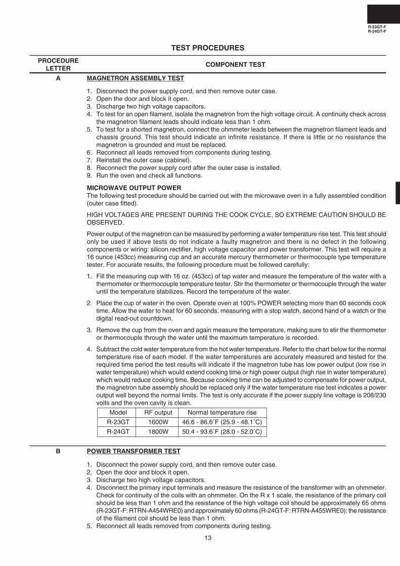
MICROWAVE OUTPUT POWERThe following test procedure should be carried out with the microwave oven in a fully assembled condition(outer case fitted).
HIGH VOLTAGES ARE PRESENT DURING THE COOK CYCLE, SO EXTREME CAUTION SHOULD BEOBSERVED.
Power output of the magnetron can be measured by performing a water temperature rise test. This test shouldonly be used if above tests do not indicate a faulty magnetron and there is no defect in the followingcomponents or wiring: silicon rectifier, high voltage capacitor and power transformer. This test will require a16 ounce (453cc) measuring cup and an accurate mercury thermometer or thermocouple type temperaturetester. For accurate results, the following procedure must be followed carefully:
1. Fill the measuring cup with 16 oz. (453cc) of tap water and measure the temperature of the water with athermometer or thermocouple temperature tester. Stir the thermometer or thermocouple through the wateruntil the temperature stabilizes. Record the temperature of the water.
2. Place the cup of water in the oven. Operate oven at 100% POWER selecting more than 60 seconds cooktime. Allow the water to heat for 60 seconds, measuring with a stop watch, second hand of a watch or thedigital read-out countdown.
3. Remove the cup from the oven and again measure the temperature, making sure to stir the thermometeror thermocouple through the water until the maximum temperature is recorded.
4. Subtract the cold water temperature from the hot water temperature. Refer to the chart below for the normaltemperature rise of each model. If the water temperatures are accurately measured and tested for therequired time period the test results will indicate if the magnetron tube has low power output (low rise inwater temperature) which would extend cooking time or high power output (high rise in water temperature)which would reduce cooking time. Because cooking time can be adjusted to compensate for power output,the magnetron tube assembly should be replaced only if the water temperature rise test indicates a poweroutput well beyond the normal limits. The test is only accurate if the power supply line voltage is 208/230volts and the oven cavity is clean.
Model RF output Normal temperature rise
R-23GT 1600W 46.6 - 86.6˚F (25.9 - 48.1˚C)
R-24GT 1800W 50.4 - 93.6˚F (28.0 - 52.0˚C)
R-23GT-FR-24GT-F
14
TEST PROCEDURES
PROCEDURELETTER COMPONENT TEST
E SECONDARY INTERLOCK SWITCH (1) AND/ OR (2) TEST
6. Reinstall the outer case (cabinet).7. Reconnect the power supply cord after the outer case is installed.8. Run the oven and check all functions.
(HIGH VOLTAGES ARE PRESENT AT THE HIGH VOLTAGE TERMINAL, SO DO NOT ATTEMPT TOMEASURE THE FILAMENT AND HIGH VOLTAGE.)
1. Disconnect the power supply cord, and then remove outer case.2. Open the door and block it open.3. Discharge two high voltage capacitors.4. Isolate the rectifier from the circuit. Using the highest ohm scale of the meter, read the resistance across
the terminals and observe, reverse the leads to the rectifier terminals and observe meter reading. If a shortis indicated in both directions, or if an infinite resistance is read in both directions, the rectifier is probablydefective and should be replaced.
5. Reconnect all leads removed from components during testing.6. Reinstall the outer case (cabinet).7. Reconnect the power supply cord after the outer case is installed.8. Run the oven and check all functions.
NOTE: Be sure to use an ohmmeter that will supply a forward bias voltage of more than 6.3 volts.
C HIGH VOLTAGE RECTIFIER (1) AND/ OR (2) TEST
D HIGH VOLTAGE CAPACITOR (1) AND/ OR (2) TEST
1. Disconnect the power supply cord, and then remove outer case.2. Open the door and block it open.3. Discharge two high voltage capacitors.4. If the capacitor is open, no high voltage will be available to the magnetron. Disconnect input leads and
check for a short or open between the terminals using an ohmmeter.Checking with a high ohm scale, if the high voltage capacitor is normal, the meter will indicate continuityfor a short time and should indicate an open circuit once the capacitor is charged. If the above is not thecase, check the capacitor with an ohmmeter to see if it is shorted between either of the terminals and case.If it is shorted, replace the capacitor.
5. Reconnect all leads removed from components during testing.6. Reinstall the outer case (cabinet).7. Reconnect the power supply cord after the outer case is installed.8. Run the oven and check all functions.
1. Disconnect the power supply cord, and then remove outer case.2. Open the door and block it open.3. Discharge two high voltage capacitors.4. Isolate the switch and connect the ohmmeter to the common (COM.) and normally open (NO) terminal of
the switch. The meter should indicate an open circuit with the door open and a closed circuit with the doorclosed. If improper operation is indicated, replace the secondary interlock switch.
5. Reconnect all leads removed from components during testing.6. Reinstall the outer case (cabinet).7. Reconnect the power supply cord after the outer case is installed.8. Run the oven and check all functions.
DOOR SENSING SWITCH1. Disconnect the power supply cord, and then remove outer case.2. Open the door and block it open.3. Discharge two high voltage capacitors.4. Isolate the switch and connect the ohmmeter to the common (COM.) and normally open (NO) terminal of
the switch. The meter should indicate an open circuit with the door open and a closed circuit with the doorclosed. If improper operation is indicated, replace the door sensing switch.
F PRIMARY INTERLOCK SYSTEM TEST
R-23GT-FR-24GT-F
15
TEST PROCEDURES
PROCEDURELETTER COMPONENT TEST
1. Disconnect the power supply cord, and then remove outer case.2. Open the door and block it open.3. Discharge two high voltage capacitors.4. Before performing this test, make sure that the secondary interlock switches (1), (2) and the primary
interlock relays RY2, RY3 are operating properly, according to the above Switch Test Procedure.Disconnect the wire lead from the monitor switches (1), (2) (COM) terminals. Check the monitor switches(1), (2) operation by using the ohmmeter as follows. When the door is open, the meter should indicate aclosed circuit. When the monitor switch actuator is pushed by a screw driver through the upper latch holeon the front plate of the oven cavity with the door opened (in this condition the plunger of the monitor switchis pushed in), the meter should indicate an open circuit. If improper operation is indicated, the switch maybe defective. After testing the monitor switches, reconnect the wire lead to the monitor switch (COM)terminals and check the continuity ofthe monitor circuit.
5. Reconnect all leads removed fromcomponents during testing.
6. Reinstall the outer case (cabinet).7. Reconnect the power supply cord after
the outer case is installed.8. Run the oven and check all functions.
5. Reconnect all leads removed from components during testing.6. Reinstall the outer case (cabinet).7. Reconnect the power supply cord after the outer case is installed.8. Run the oven and check all functions.
NOTE:If the door sensing switch contacts fail in the open position and the door is closed, the blowermotor, stirrer motors and oven light will be activated by RY1.
PRIMARY INTERLOCK RELAY (RY2, RY3)1. Disconnect the power supply cord, and then remove outer case.2. Open the door and block it open.3. Discharge two high voltage capacitors.4. Disconnect two (2) wire leads from the male tab terminals of the Primary Interlock Relay RY2 and/or RY3.
Check the state of the relay contacts using a ohmmeter. The relay contacts should be open. If the relaycontacts are closed, replace the circuit board entirely or the relay itself.
5. Reconnect all leads removed from components during testing.6. Reinstall the outer case (cabinet).7. Reconnect the power supply cord after the outer case is installed.8. Run the oven and check all functions.
G MONITOR SWITCH (1) AND/ OR (2) TEST
SCREW DRIVER
MONITOR SWITCH (2)
OHMMETER
MONITOR SWITCH (1)
LATCH HOOK
1. Disconnect the power supply cord, and then remove outer case.2. Open the door and block it open.3. Discharge two high voltage capacitors.4. Isolate switch and check the contacts by using an ohmmeter with following table. If improper operation is
indicated, make the necessary switch adjustment or replacement.
Table: Switch Connection
Plunger operation Between COM. and NO. Between COM. and NC. COM.: Common terminal
Plunger released Open circuit Close circuit NO.: Normal Open terminal
Plunger operation Close circuit Open circuit NC.: Normal Close terminal
H VOLTAGE SELECT SWITCHES TEST
5. Reconnect all leads removed from components duringtesting.
6. Reinstall the outer case (cabinet).7. Reconnect the power supply cord after the outer case is
installed.8. Run the oven and check all functions.
Select switch (1)
Select switch (2)
Select switch (3)
COM.
N.C. N.O Select switch angle
Switch spacer
ScrewOvencavityRear
cabinetside
R-23GT-FR-24GT-F
16
TEST PROCEDURES
PROCEDURELETTER
COMPONENT TEST
1. Disconnect the power supply cord, and then remove outer case.2. Open the door and block it open.3. Discharge two high voltage capacitors.4. If the monitor fuse is blown when the door is opened, check the primary interlock relays RY2, RY3,
secondary interlock switches (1), (2) and monitor switches (1), (2) according to the "TEST PROCEDURE"for those switches before replacing the blown monitor fuse.
CAUTION: BEFORE REPLACING A BLOWN MONITOR FUSE, TEST THE PRIMARY INTERLOCKRELAYS, SECONDARY INTERLOCK SWITCHES, DOOR SENSING SWITCH AND MONITORSWITCHES FOR PROPER OPERATION.
If the monitor fuse is blown by improper switch operation, the monitor fuse and monitor switch must bereplaced with "monitor fuse and monitor switch assembly" part number FFS-BA033WRKZ, even if themonitor switch operates normally. The monitor fuse and monitor switch assembly is comprised of a 20ampere fuse and switch.
5. Reconnect all leads removed from components during testing.6. Reinstall the outer case (cabinet).7. Reconnect the power supply cord after the outer case is installed.8. Run the oven and check all functions.
I BLOWN MONITOR FUSE TEST
1. Disconnect the power supply cord, and then remove outer case.2. Open the door and block it open.3. Discharge two high voltage capacitors.4. A continuity check across the temperature fuse terminals should indicate a closed circuit unless the
temperature of the temperature fuse reaches specfied temperature as shown below.
J TEMPERATURE FUSE TEST
5. Reconnect all leads removed from components during testing.6. Reinstall the outer case (cabinet).7. Reconnect the power supply cord after the outer case is installed.8. Run the oven and check all functions.
CAUTION: IF THE TEMPERATURE FUSE INDICATES AN OPEN CIRCUIT AT ROOM TEMPERATURE,REPLACE TEMPERATURE FUSE.
K THERMISTOR TEST
Magnetron (1) Failure:Test magnetron (1) and Blower fan motor.
Magnetron (1), (2) Failure: Test magnetron (1), (2).Check blower fan motor and ventilation opening.
Magnetron (2) Failure:Test magnetron (2) and Blower fan motor.
Food has been burned in oven.Temperature of oven inside is very high.
Oven temperaturefuse
Magnetron tempera-ture fuse (2)
Magnetron tem-perature fuse (1)
150˚C
120˚C
Non resetabletype
EE1
EE3
EE2
Oven shutoff
Non resetabletype
Open Close Display ortemperature temperature Condition Check point
1. Disconnect the power supply cord, and then remove outer case.2. Open the door and block it open.3. Discharge two high voltage capacitors.4. Follow the procedures below for each thermistor.
4-1. MAGNETRON THERMISTOR TESTDisconnect connector-H from the CPU unit. And disconnect the connector of the magnetron thermistor fromthe switch harness. Measure the resistance of the thermistor with an ohmmeter. Connect the ohmmeter leadsto the leads of the thermistor.
If the meter does not indicate above resistance, replace the thermistor.
4-2. OVEN THERMISTOR (1) TEST
Disconnect connector-B from the CPU unit. Measure the resistance of the thermistor with an ohmmeter.Connect the ohmmeter leads to the leads of the thermistor.
If the meter does not indicate above resistance, replace the thermistor.
4-3. OVEN THERMISTOR (2) TEST
Disconnect connector-H from the CPU unit. And disconnect the connector of the magnetron thermistor fromthe switch harness. Measure the resistance of the thermistor with an ohmmeter. Connect the ohmmeter leadsto the leads of the thermistor.
If the meter does not indicate above resistance, replace the thermistor.5. Reconnect all leads removed from components during testing.6. Reinstall the outer case (cabinet).7. Reconnect the power supply cord after the outer case is installed.8. Run the oven and check all functions.
L NOISE FILTER TEST
1. Disconnect the power supply cord, and then remove outer case.2. Open the door and block it open.3. Discharge high voltage capacitor.4. Disconnect the lead wires from the terminal the noise filter. Using
an ohmmeter, check between the terminals as described in thefollowing table. If incorrect reading are obtained, replace the noisefilter.
5. Reconnect all leads removed from components during testing.6. Reinstall the outer case (cabinet).7. Reconnect the power supply cord after the outer case is installed.8. Run the oven and check all functions.
MEASURING POINT INDICATION OF OHMMETER
Between N and L Approx. 470 KΩBetween terminal N and WHITE/ BLACK Short circuit.
Between terminal L and RED Short circuit.
FUSE 20A
NOISE FILTER
DISCHARGE RESISTOR470 K 1/2W
NOISE SUPPRESSION COIL
LINE CROSS CAPACITOR1.0µF / AC 250V
LINE BYPASS CAPACITOR
0.0033µF / AC 125V
LINE BYPASS CAPACITOR
0.0033µF / AC 125V
L
REDWHITEBLACK
N
M TOUCH CONTROL PANEL ASSEMBLY TEST
The touch control panel consists of circuits including semiconductors such as LSI, ICs, etc.Therefore, unlike conventional microwave ovens, proper maintenance cannot be performed withonly a voltmeter and ohmmeter.In this service manual, the touch control panel assembly is divided into two units, Control Unit andKey Unit, and troubleshooting by unit replacement is described according to the symptomsindicated.
R-23GT-FR-24GT-F
18
TEST PROCEDURES
PROCEDURELETTER COMPONENT TEST
Before testing,1) Disconnect the power supply cord, and then remove outer case.2) Open the door and block it open.3) Discharge two high voltage capacitors.4) Disconnect the leads to the primary of the power transformer.5) Ensure that these leads remain isolated from other components and oven chassis by using insulation
tape.1. Key Unit.
NOTE ;1) Check Key unit ribbon connection before replacement.2) Reconnect all leads removed from components during testing.3) Re-install the outer case (cabinet).4) Reconnect the power supply cord after the outer case is installed.5) Run the oven and check all functions.The following symptoms indicate a defective key unit.a) When touching the pads, a certain pad produces no signal at all.b) When touching a number pad, two figures or more are displayed.c) When touching the pads, sometimes a pad produces no signal.If the Key unit is defective.1) Disconnect the power supply cord, and then remove outer case.2) Open the door and block it open.3) Discharge two high voltage capacitors.4) Replace the Key unit.5) Reconnect all leads removed from components during testing.6) Re-install the outer case (cabinet).7) Reconnect the power supply cord after the outer case is installed.8) Run the oven and check all functions.
2. Control UnitThe following symptoms indicate a defective control unit. Before replacing the control unit, performthe Key unit test (Procedure N) to determine if control unit is faulty.Re-connect the power supply cord. And check for followings.
2-1 In connection with pads.a) When touching the pads, a certain group of pads do not produce a signal.b) When touching the pads, no pads produce a signal.
2-2 In connection with displaya) At a certain digit, all or some segments do not light up.b) At a certain digit, brightness is low.c) Only one indicator does not light.d) The corresponding segments of all digits do not light up; or they continue to light up.e) Wrong figure appears.f) A certain group of indicators do not light up.g) The figure of all digits flicker.
2-3 Other possible problems caused by defective control unit.a) Buzzer does not sound or continues to sound.b) Cooking is not possible.
When testing is completed,1) Disconnect the power supply cord, and then remove outer case.2) Open the door and block it open.3) Discharge two high voltage capacitors.4) Reconnect all leads removed from components during testing.5) Re-install the outer case (cabinet).6) Reconnect the power supply cord after the outer case is installed.7) Run the oven and check all functions.
R-23GT-FR-24GT-F
19
1. Disconnect the power supply cord, and then remove outer case.2. Open the door and block it open.3. Discharge two high voltage capacitors.4. If the display fails to clear when the STOP/CLEAR pad is depressed, first verify the flat ribbon cable is
making good contact, verify that the door sensing switch (stop switch) operates properly; that is thecontacts are closed when the door is closed and open when the door is open. If the door sensing switch(stop switch) is good, disconnect the flat ribbon cable that connects the key unit to the control unit and makesure the door sensing switch is closed (either close the door or short the door sensing switch connecter).Use the Key unit matrix indicated on the control panel schematic and place a jumper wire between the pinsthat correspond to the STOP/CLEAR pad making momentary contact. If the control unit responds byclearing with a beep the key unit is faulty and must be replaced. If the control unit does not respond, it isfaulty and must be replaced. If a specific pad does not respond, the above method may be used (afterclearing the control unit) to determine if the control unit or key pad is at fault.
5. Reconnect all leads removed from components during testing.6. Re-install the outer case (cabinet).7. Reconnect the power supply cord after the outer case is installed.8. Run the oven and check all functions.
N KEY UNIT TEST
111131519
12141620
17
18
3
4
5
6
7
8
9
0
G 8G 7G 6G 5G 4G 3G 2G 1
G 9
G 10
G 11
G 12 2
DOUBLEQUANTITY
EXPRESSDEFROST
SELECTATIME
SELECTAPOWER
STOP /CLEAR
START SET
CHECK
SIGNAL
1. Disconnect the power supply cord, and then remove outer case.2. Open the door and block it open.3. Discharge two high voltage capacitors.4. Disconnect the leads to the primary of the power transformer.5. Ensure that these leads remain isolated from other components and oven chassis by using insulation tape.6. After that procedure, re-connect the power supply cord.7. Remove the outer case and check voltage between Pins No. 5 (or No. 3 at 230V) and No. 7 of the 7 pin
connector (A) on the control unit with an A.C. voltmeter.The meter should indicate rated voltage, if not check oven circuit.
RY1, RY2 and RY3 Relay TestThese relays are operated by D.C. voltageCheck voltage at the relay coil with a D.C. voltmeter during the microwave cooking operation.
DC. voltage indicated ................... Defective relay.DC. voltage not indicated ............. Check diode which is connected to the relay coil. If diode is
good, control unit is defective.
RELAY SYMBOL OPERATIONAL VOLTAGE CONNECTED COMPONENTS
RY2 Approx. 12.0V D.C. Power transformer 1RY3 Approx. 12.0V D.C. Power transformer 2
8. Disconnect the power supply cord, and then remove outer case. 9. Open the door and block it open.10. Discharge two high voltage capacitors.11. Reconnect all leads removed from components during testing.12. Re-install the outer case (cabinet).
O RELAY TEST
TEST PROCEDURES
PROCEDURELETTER COMPONENT TEST
R-23GT-FR-24GT-F
20
TEST PROCEDURES
PROCEDURELETTER COMPONENT TEST
13. Reconnect the power supply cord after the outer case is installed.14. Run the oven and check all function.
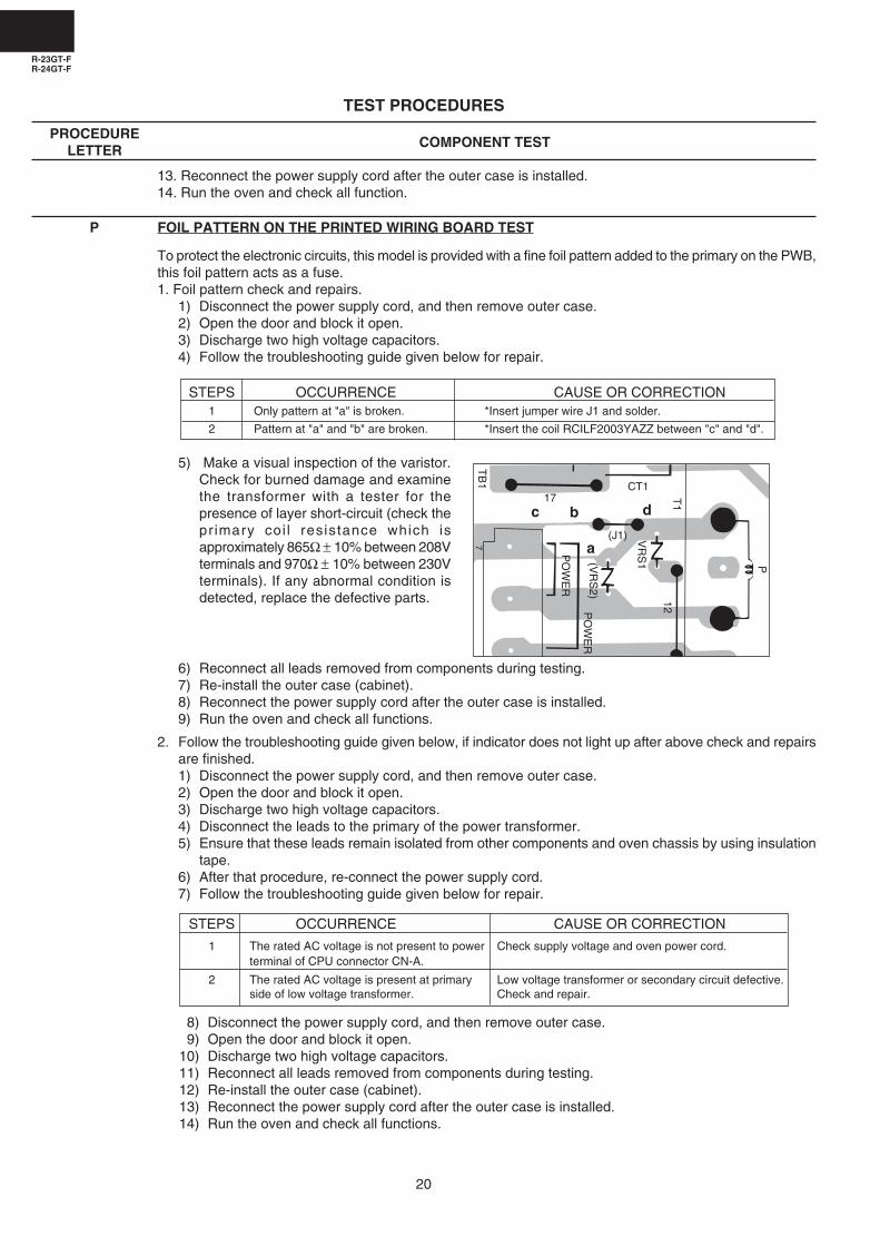
P FOIL PATTERN ON THE PRINTED WIRING BOARD TEST
To protect the electronic circuits, this model is provided with a fine foil pattern added to the primary on the PWB,this foil pattern acts as a fuse.1. Foil pattern check and repairs.
1) Disconnect the power supply cord, and then remove outer case.2) Open the door and block it open.3) Discharge two high voltage capacitors.4) Follow the troubleshooting guide given below for repair.
STEPS OCCURRENCE CAUSE OR CORRECTION1 Only pattern at "a" is broken. *Insert jumper wire J1 and solder.
2 Pattern at "a" and "b" are broken. *Insert the coil RCILF2003YAZZ between "c" and "d".
5) Make a visual inspection of the varistor.Check for burned damage and examinethe transformer with a tester for thepresence of layer short-circuit (check theprimary coi l resistance which isapproximately 865Ω ± 10% between 208Vterminals and 970Ω ± 10% between 230Vterminals). If any abnormal condition isdetected, replace the defective parts.
6) Reconnect all leads removed from components during testing.7) Re-install the outer case (cabinet).8) Reconnect the power supply cord after the outer case is installed.9) Run the oven and check all functions.
2. Follow the troubleshooting guide given below, if indicator does not light up after above check and repairsare finished.1) Disconnect the power supply cord, and then remove outer case.2) Open the door and block it open.3) Discharge two high voltage capacitors.4) Disconnect the leads to the primary of the power transformer.5) Ensure that these leads remain isolated from other components and oven chassis by using insulation
tape.6) After that procedure, re-connect the power supply cord.7) Follow the troubleshooting guide given below for repair.
STEPS OCCURRENCE CAUSE OR CORRECTION
1 The rated AC voltage is not present to power Check supply voltage and oven power cord.terminal of CPU connector CN-A.
2 The rated AC voltage is present at primary Low voltage transformer or secondary circuit defective.side of low voltage transformer. Check and repair.
8) Disconnect the power supply cord, and then remove outer case.9) Open the door and block it open.
10) Discharge two high voltage capacitors.11) Reconnect all leads removed from components during testing.12) Re-install the outer case (cabinet).13) Reconnect the power supply cord after the outer case is installed.14) Run the oven and check all functions.
7
PO
WE
R
PO
WE
R(V
RS
2)
VR
S1
(J1)
12
P
CT117
TB
1
T1
a
bc d
R-23GT-FR-24GT-F
21
TOUCH CONTROL PANEL ASSEMBLYOUTLINE OF TOUCH CONTROL PANEL
The touch control section consists of the following units asshown in the touch control panel circuit.
(1) Control Unit(2) Key Unit
The principal functions of these units and the signals commu-nicated among them are explained below.
1. Control UnitSignal of key touch and oven function control are allprocessed by one microcomputer.
1) Power Supply CircuitThis circuit changes output voltage at the secondary sideof the low voltage (T1) transformer to voltages required ateach part by full wave rectifying circuit, constant voltagecircuit, etc..
2) ACL CircuitThis is an Auto-clear Circuit, i.e., a reset circuit, whichenables IC1 to be activated from initial state.
3) Power Synchronizing Signal Generating CircuitThis is a circuit for generating power synchronizing signalby virtue of the secondary side output of transformer T1.This signal is used as a basic frequency for time process-ing.
4) Clock CircuitThis is a circuit for controlling clock frequency required foroperating IC1.
5) IC1 (Main Processor)This is a one-chip microcomputer, responsible for control-ling the entire control unit.
6) IC2 (Memory Processor)This is a memory IC, responsible for memory function.
7) IC3This is a IC for driving light emitting diode.
8) Display CircuitThis is a circuit for driving light emitting diode by IC1 output.
9) Key Input CircuitThis is a circuit for transmitting key input information to IC1.
10) Sound-body Driving CircuitThis is a circuit for driving sound body by IC1 output.
11) Relay Driving CircuitThis is a circuit for driving output relay by IC1 output.
12) Door Sensing Switch CircuitThis is a circuit for driving IC1 to detect door opening/closing.
13) Exhaust Air Temperature Detecting CircuitThis is a circuit for transmitting output change of thermistor(Oven thermistor (1)) to IC1.
14) Magnetron Temperature Circuit(Detect no load or fan lock)This is a circuit for transmitting output change of thermistor(Magnetron thermistor) to IC1.
17) Supply Voltage Detecting CircuitThis is a circuit for detecting troubles of input voltage atmicrowave oven. The function of this circuit is to divide thevariation of voltage across C1 to supply voltage variationby ZD1, R1 and R2 and to put the result to AN6 port of IC1for detection.
FIgure T-2. Supply Voltage Detecting Circuit
16) High Voltage Monitoring Circuit.This circuit detects problems in the magnetron / highvoltage circuit by sensing a variation in the current flowingthrough the primary winding of the high voltage trans-former.During heating, the primary current of the high voltagetransformers also flows through the primary winding of thecurrent transformer CT1. This causes a current to beinduced in the secondary winding of CT1 and results in anAC voltage which is determined by R100.This AC voltage is then half wave rectified by D100 andsmoothed (filtered) by C100.This AC voltage is the input to the AN3 port of IC1, whichdetermines if there is a magnetron / high voltage problem.
Figure T-1. High Voltage Monitoring Circuit
TB1
TB2
CT1 D100 R102
R10
0
C10
0
47µ/
10v
0.01
µ/16
v
R10
1
100k
820F
C10
1
4.7kTo AN3 of IC1
A 5
A 7
A 3
C1
2200
µ/25
v ZD
1R
1
470
R2
470
HZ
12B
1
VR
S2
VR
S1
(J1)
T1 10EDB10 x 4
IC1(AN6)
D1
D2 D4
D3
AC208V60Hz
AC230V60Hz
+
-
15) Oven Cavity Temperature Detecting CircuitThis is a circuit for transmitting output change of thermistor(Oven thermistor (2)) to IC1.
R-23GT-FR-24GT-F
22
VOLTAGE REGULATION FOR "ERROR" INDICATION
Voltage Input to Input toregulation 208V 230V
*Normal +6% excel. 208.0--220.48 230.0--243.8
*Normal -9% excel. 189.28--208.0 209.3--230.0
*Error.or +6% to 220.48 243.8indication +13% excel. 235.04 259.9range -9% to 189.28 209.3
-13% excel. 180.96 200.1
Not over +13% over 235.04 over 259.9cookable under -13% under 180.96 under 200.1
* Cookable Range
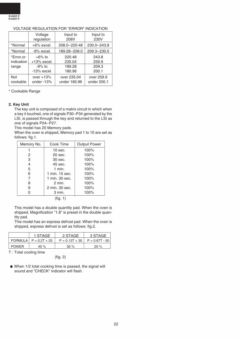
2. Key UnitThe key unit is composed of a matrix circuit in which whena key it touched, one of signals P30--P34 generated by theLSI, is passed through the key and returned to the LSI asone of signals P24--P27.This model has 20 Memory pads.When the oven is shipped, Memory pad 1 to 10 are set asfollows: fig.1.
Memory No. Cook Time Output Power
1 10 sec. 100%2 20 sec. 100%3 30 sec. 100%4 45 sec. 100%5 1 min. 100%6 1 min. 15 sec. 100%7 1 min. 30 sec. 100%8 2 min. 100%9 2 min. 30 sec. 100%0 3 min. 100%
(fig. 1)
This model has a double quantity pad. When the oven isshipped, Magnification "1.8" is preset in the double quan-tity pad.This model has an express defrost pad. When the oven isshipped, express defrost is set as follows: fig.2.
1 STAGE 2 STAGE 3 STAGEFORMULA P = 0.2T + 20 P = 0.13T + 30 P = 0.67T - 50
POWER 40 % 30 % 20 %
T : Total cooling time(fig. 2)
When 1/2 total cooking time is passed, the signal willsound and "CHECK" indicator will flash.
R-23GT-FR-24GT-F
23
Pin No. Signal I/O Description
DESCRIPTION OF LSILSI(IZA633DR)The I/O signal of the LSI(IZA633DR) is detailed in the following table.
+5V
GND
32 sec.
ON
OFF
H
L
16.7 msec
During cooking
A
0.1 sec
2 sec
1 sec
+5V
GNDT
200µsec.200µsec.
1 sec
B+5V
GND
C
+5V
GND
1 VCC IN Power source voltage: +5V.VC voltage of power source circuit input.
2/3 VEE/AVSS IN Connected to GND
4 VREF IN Connected to VC. (+5V)
5 AN7 IN Temperature measurement input: INTAKE THERMISTOR.By inputting DC voltage corresponding to the temperature detected by the thermistor, thisinput is converted into temperature by the A/D converter built into the LSI.
6 AN6 IN Used (judge for input voltage).
7-8 AN5-AN4 IN Terminal to change functions according to the model.Signal in accordance with the model in operation is applied to set up its function.
9 AN3 IN A/D input for troubleshooting Magnetron 1. and/or Magnetron 2.
10 AN2 IN Temperature measurement input: OVEN THERMISTOR.By inputting DC voltage corresponding to the temperature detected by the thermistor, thisinput is converted into temperature by the A/D converter built into the LSI.
11 AN1 IN Input signal which communicates the door open/close information to LSI.Door closed; "L" level signal (0V).Door opened; "H" level signal (+5V).
12 AN0 IN Temperature measurement input: FAN LOCK THERMISTOR.By inputting DC voltage corresponding to the temperature detected by the thermistor, thisinput is converted into temperature by the A/D converter built into the LSI.
13-14 P55-P54 OUT Magnetron high-voltage circuit driving signal.To turn on and off the cook relay. In 100% power level operation, "H" level during cooking;"L" level otherwise. In other power level operation (90,80,70,60,50,40,30,20,10 or 0%), "H"and "L" level is repeated according to power level.
Power level ON OFF Power level ON OFF
100% 32sec. 0sec. 40% 16sec. 16sec.
90% 30sec. 2sec. 30% 12sec. 20sec.
80% 26sec. 6sec. 20% 8sec. 24sec.
70% 24sec. 8sec. 10% 6sec. 26sec.
60% 22sec. 10sec. 0% 0sec. 32sec.
50% 18sec. 14sec.
15 P53 OUT Oven thermistor circuit power supply control signal.Output the "H" signal to supply power to oven thermistor circuit about 1.7msec. after pluggingin.
16-18 P52-P50 IN Terminal not used.
19 P47 OUT Signal to sound buzzer.This signal is to control the 2.5kHz continuoussignal through IC3.A: key touch sound.B: Guydance sound.C: Completion sound.
20 P46 OUT Oven lamp, Blower motor and Stirrer motor driving signal. (Square Waveform : 60Hz)To turn on and off the shut-off relay (RY1). TheSquare waveform voltage is delivered to the RY1driving circuit and relays(RY2,RY3,COOK RELAY)control circuit.
R-23GT-FR-24GT-F
24
Pin No. Signal I/O Description
H
L
+5V
ß(60Hz)
P42
P43
P44
P45
GND
H : +5V
L : GND
16.7 msec
+5V
GND
ß(60Hz)
21 P45 OUT Digit selection signal.The relation between digit signal and digit are asfollows:Digit signal DigitP42 ..................... 1st.P43 .................... 2nd.P44 ..................... 3rd.P45 ..................... 4th.
Normally, one pulse is output in every ß period,and input to the grid of the light-emitting diode.
22-24 P44-P42 OUT Digit selection signal.Signal similar to P45.
25 INT1 IN Signal synchronized with commercial power source frequency.This is basic timing for all time processing of LSI.
26 INT0 IN Connected to GND through resistor.
27 RESET IN Auto clear terminal.Signal is input to reset the LSI to the initial state when power is supplied. Temporarily setto "L" level the moment power is supplied, at this time the LSI is reset. Thereafter set at "H"level.
28 P71 OUT Memory (EEPROM) clock output.
29 P70 IN/OUT Memory (EEPROM) data input/output.
30 XIN IN Internal clock oscillation frequency setting input.The internal clock frequency is set by inserting the ceramic filter oscillation circuit withrespect to XOUT terminal.
31 XOUT OUT Internal clock oscillation frequency control output.Output to control oscillation input of XIN.
32 VSS IN Connected to GND.
33 P27 IN Signal coming from touch key.When either one of G-12 line keys on key matrix is touched, a corresponding signal out ofP30, P31, P32, P33, P34 will be input into P27. When no key is touched, the signal is heldat "L" level.
34 P26 IN Signal similar to P27.When either one of G-11 line keys on key matrix is touched, a corresponding signal will beinput into P26.
35 P25 IN Signal similar to P27.When either one of G-10 line keys on key matrix is touched, a corresponding signal will beinput into P25.
36 P24 IN Signal similar to P27.When either one of G-9 line keys on key matrix is touched, a corresponding signal will beinput into P24.
37-38 P23-P22 OUT Terminal not used.
39-40 P21-P20 OUT Segment data signals.The relation between signals and indicators are as follows:Signal Segment Signal SegmentP21,P20 .......... 1 P05,P04 .............7P17.P16 .......... 2 P03,P02 .............8P15,P14 .......... 3 P01,P00 .............9P13,P12 .......... 4P11,P10 .......... 5P07,P06 .......... 6
R-23GT-FR-24GT-F
25
Pin No. Signal I/O Description
X24C02P is a 2K-bit, serial memory, enabling CMOS to be erased/written electrically. This memory is constructed with 256registers x 8bits, enabling individual access, read and write operations to be performed. Details of input/output signal for IC2 areas shown in the following diagram.
2-2 Memory IC (IC2)
FUNCTIONAL DIAGRAM
E PROM256 x 82
STARTSTOPLOGIC
CONTROLLOGIC
SLAVE ADDRESSREGISTER
COMPARATOR
H.V. GENERATIONTIMING
& CONTROL
64
YDEC
8
DATA REGISTERDout
CK
3
15
64XDEC
START CYCLE
INCLOAD
WORDADDRESSCOUNTER
R/W
PIN
DoutACK
(6) SCL
(5) SDA
(4) Vss
(3) Vcc
Figure T-3 Relation between Pin Nos, and Signals
A0
A1
A2
VSS
VCC
TEST
SCL
SDA
TOP VIEW
1
2
3
4
8
7
6
5
Pin No. Signal I/O Description1-3 A0-A2 IN Connected to +5V.4 VSS IN Connected to GND.5 SDA IN/OUT Serial data input/output : input/outputs data to IC1.6 SCL IN Clock signal input : input/outputs sireal data at every one pulse.7 TEST IN Connected to GND.8 VCC IN Connected to +5V.
41-48 P17-P10 OUT Segment data signal.Signal similar to P21.
49-56 P07-P00 OUT Segment data signal.Signal similar to P21.
57-59 P37-P35 OUT Terminal not used.
60 P34 OUT Key strobe signal.Signal applied to touch-key section. A pulse signal is input to P27, P26, P25 and P24terminals while one of G4 line keys on key matrix is touched.
61 P33 OUT Key strobe signal.Signal applied to touch-key section. A pulse signal is input to P27, P26, P25 and P24terminals while one of G5 line keys on key matrix is touched.
62 P32 OUT Key strobe signal.Signal applied to touch-key section. A pulse signal is input to P27, P26, P25 and P24terminals while one of G6 line keys on key matrix is touched.
63 P31 OUT Key strobe signal.Signal applied to touch-key section. A pulse signal is input to P27, P26, P25 and P24terminals while one of G7 line keys on key matrix is touched.
64 P30 OUT Key strobe signal.Signal applied to touch-key section. A pulse signal is input to P27, P26, P25 and P24terminals while one of G8 line keys on key matrix is touched.
R-23GT-FR-24GT-F
26
SERVICING
3. Servicing of Touch Control PanelWe describe the procedures to permit servicing of thetouch control panel of the microwave oven and theprecautions you must take when doing so. To perform theservicing, power to the touch control panel is availableeither from the power line of the oven itself or from anexternal power source.
(1) Servicing the touch control panel with powersupply of the oven:CAUTION:THE HIGH VOLTAGE TRANSFORMER OF THEMICROWAVE OVEN IS STILL LIVE DURINGSERVICING AND PRESENTS A HAZARD.Therefore, before checking the performance of the touchcontrol panel,1) Disconnect the power supply cord, and then remove
outer case.2) Open the door and block it open.3) Discharge high voltage capacitor.4) Disconnect the leads to the primary of the power
transformer.5) Ensure that these leads remain isolated from other
components and oven chassis by using insulation tape.6) After that procedure, re-connect the power supply cord.
After checking the performance of the touch control panel,1) Disconnect the power supply cord.2) Open the door and block it open.3) Re-connect the leads to the primary of the power
transformer.4) Re-install the outer case (cabinet).
approx. 1M ohm
5) Re-connect the power supply cord after the outer caseis installed.
6) Run the oven and check all functions.A. On some models, the power supply cord between the touch
control panel and the oven itself is so short that the two can’tbe separated. For those models, check and repair all thecontrols (sensor-related ones included) of the touch controlpanel while keeping it connected to the oven.
B. On some models, the power supply cord between the touchcontrol panel and the oven proper is long enough that theymay be separated from each other. For those models, it ispossible to check and repair the controls of the touch controlpanel while keeping it apart from the oven proper; in thiscase you must short both ends of the door sensing switch(on PWB) of the touch control panel with a jumper, whichactivates an operational state that is equivalent to the ovendoor being closed. As for the sensor-related controls of thetouch control panel, checking them is possible if dummyresistor(s) with resistance equal to that of the controls areused.
(2) Servicing the touch control panel with power supplyfrom an external power source:Disconnect the touch control panel completely from theoven proper, and short both ends of the door sensing switch(on PWB) of the touch control panel, which activates anoperational state that is equivalent to the oven door beingclosed. Connect an external power source to the powerinput terminal of the touch control panel, then it is possibleto check and repair the controls of the touch control panelit is also possible to check the sensor-related controls of thetouch control panel by using the dummy resistor(s).
4. Servicing ToolsTools required to service the touch control panel assembly.
1) Soldering iron: 30W(It is recommended to use a soldering iron with a groundingterminal.)
2) Oscilloscope: Single beam, frequency range: DC-10MHztype or more advanced model.
3) Others: Hand tools
5. Other Precautions1) Before turning on the power source of the control unit,
remove the aluminium foil applied for preventing staticelectricity.
2) Connect the connectors of the key unit to the control unitbeing sure that the lead wires are not twisted.
3) After aluminium foil is removed, be careful that abnormalvoltage due to static electricity etc. is not applied to the inputor output terminals.
4) Attach connectors, electrolytic capacitors, etc. to PWB,making sure that all connections are tight.
5) Be sure to use specified components where high precisionis required.
1. Precautions for Handling Electronic ComponentsThis unit uses CMOS LSI in the integral part of the circuits.When handling these parts, the following precautions shouldbe strictly followed. CMOS LSI have extremely highimpedance at its input and output terminals. For this reason,it is easily influenced by the surrounding high voltage powersource, static electricity charge in clothes, etc. andsometimes it is not fully protected by the built-in protectioncircuit.In order to protect CMOS LSI.
1) When storing and transporting, thoroughly wrap themin aluminium foil. Also wrap all PW boards containingthem in aluminium foil.
2) When soldering, ground the technician as shown inthe figure and use grounded soldering iron and worktable.
2. Shapes of Electronic Components
EC B
ICKIA7805PI
TransistorDTA123ESDTB143ESDTD143ESKRA101MKRC101M
32
1
R-23GT-FR-24GT-F
27
3) Practice for inputting total using times (Ex. 310000 times).
... Flashing / ... 0.1sec BUZZER
PAD DISPLAY INDICATOR TONE(Door close) .
.CHECK . CHECK No.CHECK 82 68 CHECK
(user total count)
SIGNALSIGNALDOUBLE 34 56QUANTITY (service total count upper figure)
3456XX
2 2 No.
(after 1 sec.) 78(service total count lower figure)XXXX78
1 1 No.
(after 1 sec.) 34 56SET 0
3,1,0,0 31 00 x 4SET 31 00
2 2 No.
(after 1 sec.) 78SET 00 0SET 0
(service total count 310000 set)
CHECK .
PROCEDURE FOR CHECKING/CLEARINGSERVICE COUNTS OF MICROWAVE OVENThe following procedure enables the servicer to obtain the totalusing times (cook cycles) since the microwave oven is pur-chased and the total operation time (hours) since the micro-wave oven is purchased. The maximum capacity of the totalusing is 999,999 times, and the maximum capacity of totaloperation time is 999,999 hours.
1) Practice for checking total using times (Ex. 345678 times).... Flashing / ... 0.1sec BUZZER
PAD DISPLAY INDICATOR TONE
(Door close) .
.
CHECK . CHECK No.
CHECK 82 68 CHECK
(user total count)
SIGNAL
SIGNAL
DOUBLE 34 56
QUANTITY (service total count upper figure)
3456XX
1 (No 1) 1 No.
(after 1 sec.) 34 56
(service total count upper figure)
2 (No 2) 2 No.
(after 1 sec.) 78
(service total count lower figure)
CHECK .
2) Practice for checking total operation time (Ex. 4567 hours).... Flashing / ... 0.1sec BUZZER
PAD DISPLAY INDICATOR TONE
(Door close) .
.
CHECK . CHECK No.
CHECK 82 68 CHECK
(user total count)
SIGNAL
SIGNAL
DOUBLE 34 56
QUANTITY (service total count upper figure)
3456XX
9 (No 9) 9 No.
(after 1 sec.) 45
(Total operation time upper figure)
0 (No 0) 0 No.
(after 1 sec.) 67
(Total operation time lower figure)
CHECK .
4) Practice for inputting total operation time (Ex. 1234 hours).... Flashing / ... 0.1sec BUZZER
PAD DISPLAY INDICATOR TONE(Door close) .
.CHECK . CHECK No.CHECK 82 68 CHECK
(user total count)
SIGNALSIGNALDOUBLE 34 56QUANTITY (service total count upper figure)
3456XX
9 9 No.
(after 1 sec.) 45SET 01,2 12 x 2SET 12
0 10 No.
(after 1 sec.) 67SET 03,4 34 x 2SET 34
(Total operation time 1234 hours set)
CHECK .
R-23GT-FR-24GT-F
28
2) To check the constants of Express defrost.
" ": Flicker / : 0.1 sec BUZZER
PAD DISPLAY INDICATOR TONE.
CHECK . "No." CHECKEXPRESS DEFROST 0.20 DEF
( A )20
( +-B )
P - 40( PL )
0.13( A )
30( +-B )
P - 30( PL )
5( pause time )
P - 20( PL )
( repeat )
CHECK .
3) To set user countsPractice for inputting total number of using times (Ex.3100 times), and using times of Memory 1 (Ex. 100times).
1. To set the standard voltageWhen the IC2 is changed in the control unit, the standard voltage must be set again for power supply check.The power supply must be set 230V within ± 1V, and 230V connector in control unit installed.
PAD ORDER DISPLAY TONE(230V power)(Door close) (BLANK)
(Plug in) .SIGNAL .DOUBLE .
SET .All
CHECK 0633 indicatorsON
(plug off) (BLANK)
NOTE :1. This procedure must be performed within 1 minute.2. When IC2 malfunctions the unit does not function normally (correct cooking data is not output, data is not stored
correctly in memory, etc.).3. Initialization of memory after repairing the touch control panel.
After repairing the touch control panel, reset all counters to 0 (including service counter). Make sure that the constant which is statedon page 22 (fig.2) has been memorized. If it mismatches, input the constant according to "EXPRESS DEFROST" on page 28.
A CHECK PROCEDURE FOR ERROR CODE INDICATION EE1, EE2
When the error code EE1 or EE2 is displayed, carry out following procedures and find out the defective parts. When oscillation isunstable due to defect of upper and/or lower magnetron or defective driving circuits, error code indications EE1 or EE2 do notfunction properly.
[CHECK METHOD FOR ERROR CODE INDICATION]Put water in a cup and place inside the oven inside, and operate each circuit separately.And check working of each circuit by temperature rise of the water and judge which magnetron circuit is defect.After judging, please replace or repair applicable part according to the troubleshooting guide in the service manual.
[CAUTION ABOUT HIGH VOLTAGE]There is high voltage present inside, disconnect the power supply cord from the outlet before removing the outer case.Reinstall the outer case when operate the unit.
[JUDGMENT PROCEDURE]1]. PREPARATION FOR JUDGMENT1. Disconnect the plug from the outlet.2. Remove the air filter and unscrew two screws at the control panel lower holding the control panel.3. Push up the control panel and pull it toward.
R-23GT-FR-24GT-F
30
2]. [JUDGMENT PROCEDURE FOR UPPER MAGNETRON AND ITS CIRCUIT]
Disconnect the power supply cord.
Disconnect lead wires to the interlock relay RY3 to avoid operation of lower magnetron circuit.
Reconnect power supply
Heating for one minute.
Temperature of the water increased?*1
Yes
EE2 should be indicated.Upper magnetron, its driving circuit and parts on the circuit are normal.
*1: CHECK OF TEMPERATURE RISEFill approx. 453 CC of water in a measuring cup and place it in the oven.Operate the oven for one minute.Substract cold water temperature from hot water temperature.The result should be approx. 18 - 36F (10 - 20 deg. C).
3]. [JUDGMENT PROCEDURE FOR LOWER MAGNETRON AND ITS CIRCUIT]
Disconnect the power supply cord.
Disconnect lead wires to the interlock relay RY2 to avoid operation of lower magnetron circuit. Lead wires to the interlockrelay RY3 should be connected.
Reconnect power supply
Heating for one minute.
Temperature of the water increased?*1
Yes
EE1 should be indicated.Lower magnetron, its driving circuit and parts on the circuit are normal.
*1: CHECK OF TEMPERATURE RISEFill approx. 453 CC of water in a measuring cup and place it in the oven.Operate the oven for one minute.Substract cold water temperature from hot water temperature.The result should be approx. 18 - 36F (10 - 20 deg.C).
If EE2 is indicated, carry out Test procedures A-J and findout the defective part. Lower magnetron, its driving circuitor any parts on its circuit may be defective.
No
If EE1 is indicated, carry out Test procedures A-J and find outthe defective part. Upper magnetron, its driving circuit or anyparts on its circuit may be defective.
No
R-23GT-FR-24GT-F
31
To remove the components, procedure as follows.1. Disconnect the power supply cord.2. Remove the screws from the rear and along side the edge
of the outer case.3. Slide the case back about 1 inch (3 cm) to free it from the
oven cavity.4. Lift entire case from the unit.5. DISCHARGE TWO HIGH VOLTAGE CAPACITORS
BEFORE TOUCHING ANY OVEN COMPONENTS ORWIRING.
6. Now, outer case is free.
To remove rear cabinet and power supply cord:7. Remove the screws holding the rear cabinet to the oven
cavity and blower motor.8. Remove the one (1) screws holding the switch mounting
angle to the rear cabinet and release the switch mountingangle from the rear cabinet.
9. Disconnect the power supply cord from the supply harness.10.Remove the one (1) screws holding the grounding wire of
power supply cord to the oven cavity.11.Remove the rear cabinet with the power supply cord from
the oven cavity.12. Loosen the tab of the cord bushing, and remove the power
supply cord with the cord bushing from the rear cabinet.13.Remove the cord bushing from the power supply cord,14.Now, the power supply cord and rear cabinet are free.
Microwave ovens contain circuitry capable of producing very high voltage and current, contact with following parts may resultin severe, possibly fatal, electric shock.(Example)High Voltage Capacitor, Power Transformer, Magnetron, High Voltage Rectifier Assembly, High Voltage Harness etc..
WARNING: Avoid possible exposure to microwave energy. Please follow the instructions below beforeoperating the oven.
WARNING AGAINST HIGH VOLTAGE:
OUTER CASE, REAR CABINET AND POWER SUPPLY CORD REMOVAL
COMPONENT REPLACEMENT AND ADJUSTMENT PROCEDURE
To prevent an electric shock, take the following precau-tions.1. Before wiring,
1) Disconnect the power supply cord.2) Open the door and block it open.3) Discharge the two high voltage capacitors and wait for
60 seconds.2. Don’t let the wire leads touch to the followiong parts;
1) High voltage parts:Magnetron, High voltage transformer, High voltagecapacitor, High voltage rectifier assembly and Highvoltage wire.
2) Hot parts:Oven lamp, Magnetron, High voltage transformer, and
WARNING FOR WIRING
1. Disconnect the power supply cord.2. Make sure that a definite “click” can be heard when the
microwave oven door is unlatched. (Hold the door in aclosed position with one hand, then pull the door releaselever with the other, this causes the latch leads to rise, itis then possible to hear a “click” as the door switchesoperate.)
3. Visually check the door and cavity face plate for damage(dents, cracks, signs of arcing etc.).
Carry out any remedial work that is necessary before operat-ing the oven.Do not operate the oven if any of the following conditions exist;1. Door does not close firmly.
2. Door hinge, support or latch hook is damaged.3. The door gasket or seal is damaged.
4. The door is bent or warped.5. There are defective parts in the door interlock system.6. There are defective parts in the microwave generating
and transmission assembly.7. There is visible damage to the oven.
Do not operate the oven:1. Without the RF gasket (Magnetron).2. If the wave guide or oven cavity are not intact.3. If the door is not closed.4. If the outer case (cabinet) is not fitted.
Oven cavity.3) Sharp edge:
Bottom plate, Oven cavity, Waveguide flange, Chassissupport and other metallic plate.
4) Movable parts (to prevent a fault)Blower fan blade, Blower fan motor, Switches, Switchlevers, Antenna motor and Sirrer antennas.
3. Do not catch the wire leads in the outer case cabinet.4. Insert the positive lock connector until its pin is locked and
make sure that the wire leads do not come off even if thewire leads are pulled.
5. To prevent an error function, connect the wire leadscorrectly, referring to the Pictorial Diagram.
Please refer to ‘OVEN PARTS, CABINET PARTS, CONTROL PANEL PARTS, DOOR PARTS’, when carrying out any of thefollowing removal procedures:
R-23GT-FR-24GT-F
32
POWER TRANSFORMERS (1) AND/OR (2) REMOVAL
Removal1. Disconnect the power supply cord and then remove outer
case and rear cabinet, referring to "OUTER CASE, REARCABINET AND POWER SUPPLY CORD REMOVAL".
2. Open the oven door and block it open.3. Discharge two high voltage capacitors.4. Remove the two (2) screws holding magnetron exhaust
duct to upper and lower waveguide.5. Remove the magnetron exhaust duct from oven cavity.6. Disconnect wire leads from magnetrons (1) and/or (2).7. Disconnect magnetron thermistor from the connector of the
stop switch harness.8. Remove the one (1) screw holding the thermistor angle to
the upper magnetron.
MAGNETRONS (1) AND/OR (2) REMOVAL
9. Remove the four (4) screws holding each magnetron (1)and/or (2) to upper and/or lower waveguide. When removingthe screws, hold the magnetron to prevent it from falling.
10.Remove the magnetrons (1) and/or (2) from upper and/orlower waveguide with care so magnetron antenna is not hitby any metal object around antenna.
11.Pull out the thermistor angle from the upper magnetron (1).12.Remove the thermo-contactor from the upper magnetron
(1).13.Now, the magnetrons (1) and/or (2) are free.
CAUTION: WHEN REPLACING MAGNETRON, BE SURETHE R.F. GASKET IS IN PLACE AND MOUNT-ING SCREWS ARE TIGHTENED SECURELY.
Removal1. Disconnect the power supply cord and then remove outer
case and rear cabinet, referring to "OUTER CASE, REARCABINET AND POWER SUPPLY CORD REMOVAL".
2. Open the oven door and block it open.3. Discharge two high voltage capacitors.4. Remove the upper magnetron from the upper waveguide
flange, referring to "MAGNETRON (1) AND /OR (2)REMOVAL".
5. Now, the upper magnetron with the magnetron thermistorshould be free.
6. Remove the thermistor angle from the upper magnetron bypulling out.
7. Straighten the tab of the magnetron thermistor angle holdingthe magnetron thermistor.
8. Remove the magnetron thermistor from the thermistorangle.
9. Now, the magnetron thermistor is free.
Re-install1. Apply the silicone grease (Shinetsu silicone grease G746 of
Shinetsu Chemical Co. Ltd.) to the thermo-contactor andthe magnetron thermistor.
2. Insert the thermo-contactor between the 1st. fin and the2nd. fin.
3. Install the magnetron thermistor to the thermistor angle asshown in Figure C-1.
4. Hold the magnetron thermistor to the thermistor angle bybending the tab of the thermistor angle.
5. Insert the thermistor angle between the 2nd. fin and 3rd. finfrom the upper fin of the upper magnetron and push it untilthe thermistor angle stops.
MAGNETRON THERMISTOR REPLACEMENT
NOTE:The magnetron thermistor should be between theupper fin and the 2nd. fin.
6. Re-install the upper magnetron to the upper waveguideflange with four (4) screws.
7. Re-install the thermistor angle to the upper waveguideflange with one (1) screw.
8. Re-install the magnetron exhaust duct to the upper andlower waveguide flanges with two (2) screws.
9. Route the thermistor harness under the magnetrontemperature fuse.
10.Connect the thermistor harness to the stop switch harness.11.Connect the wire leads to the upper magnetron, referring to
the pictorial diagram.12.Re-install the power supply cord, rear cabinet and outer
case cabinet to the oven by reversing the procedures of"OUTER CASE, REAR CABINET AND POWER SUPPLYCORD REMOVAL".
CAUTION: WHEN REPLACING MAGNETRON, BE SURETHE R.F. GASKET IS IN PLACE AND MOUNT-ING SCREWS ARE TIGHTENED SECURELY.
1. Disconnect the power supply cord and then remove outercase and rear cabinet, referring to "OUTER CASE, REARCABINET AND POWER SUPPLY CORD REMOVAL".
2. Open the oven door and block it open.3. Discharge two high voltage capacitors.4. Disconnect wire leads of power transformers (1) and/or (2)
from magnetrons (1) and/or (2).5. Remove the wire leads of power transformers from the wire
holder.6. Pull out the wire leads of power transformers from the tube.7. Disconnect wire leads of power transformers (1) and/or (2)
from high voltage capacitors (1) and/or (2).8. Disconnect the high voltage wire lead(s) from power
transformers (1) and/or (2).9. Disconnect the main wire harness from power transformers
(1) and/or (2).10.Remove two (2) screws holding each power transformer (1)
and/or (2) to base plate.11.Remove the power transformers (1) and/or (2) from base
plate.12.Now, power transformers (1) and/or (2) are free.
Upper magnetron
Upper fin
Apply grease here.
Thermo contactor
Tab
Thermistorangle
Magnetron thermistor
Figure C-1. Magnetron thermistor installation
R-23GT-FR-24GT-F
33
1. Disconnect the power supply cord and then remove outercase and rear cabinet , referring to "OUTER CASE, REARCABINET AND POWER SUPPLY CORD REMOVAL".
2. Open the oven door and block it open.3. Discharge two high voltage capacitors.4. Remove two (2) screws holding ground side terminals of
high voltage rectifier assembly to the capacitor holder andoven cavity.
5. Disconnect all wire leads from the high voltage capacitor.6. Disconnect wire leads of high voltage rectifier assembly
from the power transformers (1) and/or (2).Now, high voltage assembly is free.
7. Remove the three (3) screws holding the blower motor tothe top of oven cavity, the chassis support and air duct.
8. Remove two (2) screws holding the capacitor holder tooven cavity.
HIGH VOLTAGE CAPACITOR AND HIGH VOLTAGE RECTIFIER ASSEMBLY REMOVAL
Now, the capacitors (1), (2) and the high voltage rectifierassembly are free.
CAUTION:1. DISCHARGE THE TWO HIGH VOLTAGE CAPACITOR
BEFORE TOUCHING ANY OVEN COMPONENTS ORWIRING.
2. DO NOT REPLACE ONLY THE HIGH VOLTAGERECTIFIER. IF IT IS DEFECTIVE, REPLACE THE HIGHVOLTAGE RECTIFIER ASSEMBLY.
3. WHEN REPLACING THE HIGH VOLTAGE RECTIFIERASSEMBLY AND THE HIGH VOLTAGE CAPACITOR,THE GROUND SIDE TERMINAL OF THE HIGH VOLTAGERECTIFIER MUST BE SECURED FIRMLY WITH AGROUNDING SCREW.
Procedure1. Disconnect the power supply cord and then remove outer
case and rear cabinet, referring to "OUTER CASE, REARCABINET AND POWER SUPPLY CORD REMOVAL".
2. Open the oven door and block it open.3. Discharge two high voltage capacitors.4. Pushing the lever of positive lock® connector, pull down the
connector from the terminal.5. Now, the connector is free.
Note: If the positive lock® has a insulation sleeve, firstremove it. If you do not, you can not push the leverof positive lock®.
CAUTION: THE POSITIVE LOCK® TERMINAL CAN NOT BEREMOVED BYJUST PULLING ON IT. THE LOCKLEVER MUST BE RELEASED TO REMOVE THECONNECTOR FROM THE TERMINAL.
HOW TO RELEASE THE POSITIVE LOCK® CONNECTOR.
Figure C-2. How to release the positive lock connector.
1. Disconnect the power supply cord and then remove outercase and rear cabinet, referring to "OUTER CASE, REARCABINET AND POWER SUPPLY CORD REMOVAL".
2. Open the oven door and block it open.3. Discharge two high voltage capacitors.4. Disconnect the main wire harness from the blower motor
and noise filter.5. Remove the two (2) screws holding the blower motor angle
BLOWER MOTOR REMOVAL
to the oven cavity.6. Remove the one (1) screw holding the blower motor angle
to the chassis support.7. Remove the blower motor from the oven cavity.8. Remove the two (2) screws holding the noise filter angle to
the blower motor.9. Now, the blower motor is free.
Terminal
Push
Pull down
1
Lever
Positive lock®connector
2
STIRRER MOTORS (UPPER AND LOWER) REMOVALUPPER1. Disconnect the power supply cord and then remove outer
2. Open the oven door and block it open.3. Discharge two high voltage capacitors.4. Disconnect the wire leads from the stirrer motor (upper).5. Remove the one (1) screw holding the stirrer motor (upper)
to the oven cavity.6. Turn and lift up the stirrer motor (upper).7. Now, the stirrer motor (upper) is free.LOWER1. Disconnect the power supply coed.
2. Remove the stirrer motor cover by snipping off the materialin four portions.
3. Where the portions have been snipped off bend the portionsflat. No sharp edge must be evident after removal of thestirrer motor cover.
4. Disconnect the wire leads from the stirrer motor (lower).5. Remove the one (1) screw holding the stirrer motor (Lower)
to the oven cavity.6. Now, the stirrer motor (lower) is free.7. After replacement use one (1) screw to fit the stirrer motor
cover. (This screw has been fitted to the base plate near thestirrer motor cover beforehand.)
R-23GT-FR-24GT-F
34
VOLTAGE SELECT SWITCH REMOVAL
DOOR SENSING SWITCH/SECONDARY INTERLOCK SWITCHES (1), (2) AND MONITORSWITCHES (1), (2) REPLACEMENT
B
A C
B
Fig. 1 Fig. 2
TOUCH CONTROL PANEL
SCREW DRIVER
CONTROL PANEL ASSEMBLY REMOVALThe complete control panel should be removed for replace-ment of components. To remove the control panel, proceed asfollows:1. Disconnect the power supply cord.2. Remove the air intake filter assembly from the base plate.3. Remove two (2) screws holding the control panel to the
base plate.4. Pull down the control panel and remove it forward.5. Disconnect connectors (A), (B), (D), (H), wiring from tab
terminal 1 and 2 and wiring from RY1 and RY2.6. Now the control panel assembly is free.
CAUTION FOR TOUCH CONTROL PANEL REMOVAL1) Hold the lower end (Position A, Fig. 1) of the touch control panel
assembly firmly while sliding it down and toward you.
DO NOT FORCE THE CONTROL UNIT TO SLIDE DOWNDURING REMOVAL. THIS MAY CAUSE DAMAGE TO THECONTROL UNIT BY HITTING THE TAB TERMINALS LO-CATED AT THE FRONT OF THE OVEN CAVITY.
2) If the Touch Control Panel is hard to remove;(1) Insert a flat head screw driver into space B . (Fig. 1)(2) Rotate the screwdriver clockwise while holding position C
of the Touch Control Panel. (Fig. 2)
TO AVOID DAMAGE TO TOUCH CONTROL PANEL, COVERTHE TIP OF SCREWDRIVER WITH TAPE.
Replacement of individual component is as follows:
CONTROL UNIT AND CONTROL PANEL FRAME(WITH KEY)7. Remove two (2) screws holding the control panel mounting
angle to the panel frame.8. Lift up the control panel mounting angle from the panel
frame.9. Disconnect connector (G) from the control unit by pushing
the hooks of cable holder inwardly.10.Remove five (5) screws holding the control unit to the panel
frame assembly.11.Push down the right side two (2) hooks fixing the control unit
to the panel frame assembly, and lift up the control unit
CONTROL PANEL ASSEMBLY AND CONTROL UNIT REMOVAL
upward.12.Now, the control unit and control panel frame (with key) are
free.
CAUTION:When installing the control unit into the control panelframe:1. Be careful not to damage any of the components on the
control unit.2. When inserting key units ribbon cable through the
frame, ensure it is not pinched or bent. Ensure thecontrol unit is pushed upward to lock into the controlpanel frame prior to screwing the control unit into theframe.
3. Ensure there are not any wires near the varistors, if theexplode, they may damage the wires.
NOTE: 1. Before attaching a new key unit, removeremaining adhesive on the control panel framesurfaces completely with a soft cloth soaked inalcohol.
2. When attaching the key unit to the control panelframe, adjust the upper edge and right edge ofthe key unit to the correct position of controlpanel frame.
3. Stick the key unit firmly to the control panel frameby rubbing with soft cloth to prevent scratching.
1. Disconnect the power supply cord and then remove outercase and rear cabinet, referring to "OUTER CASE, REARCABINET AND POWER SUPPLY CORD REMOVAL".
2. Now, the switch mounting angle should be removed fromthe rear cabinet.
3. Remove the two (2) screws and the two (2) nuts holding the
voltage select switches and the switch spacer to the switchmounting angle.
4. Remove the voltage select switches and the switch spacerf rom the switch mounting angle.
5. Now, the voltage select switches are free.
REMOVAL1. Disconnect the power supply cord and then remove outer
2. Open the oven door and block it open.3. Discharge two high voltage capacitors.
4. Remove outer control panel reffering to "CONTROL PANELASSEMBLY AND CONTROL UNIT REMOVAL".
5. Disconnect all wire leads from the all switches.6. Remove two (2) screws holding latch hook to oven flange.7. Remove latch hook assembly from oven flange.8. Remove the switch(es) in accordance with following
R-23GT-FR-24GT-F
35
procedure.DOOR SENSING SWITCH
Push the two (2) tabs outward and pull switch forwards torelease switch.
MONITOR SWITCHES OR SECONDARY INTERLOCKSWITCHESRemove one (1) screw and nut holding two switches togetherto latch hook.
8. Now, switch(es) is now free.
RE-INSTALL1. Re-install the switch(es) in accordance with following
procedure.DOOR SENSING SWITCH
Mount the door sensing switch in the lower position of latchhook.
MONITOR SWITCHES1) Mount the two (2) switches side by side in the top position
of the latch hook.2) Fasten both switches together to latch hook with one (1)
screw and nut.SECONDARY INTERLOCK SWITCHES1) Mount the two (2) switches side by side in the middle
position of the latch hook.2) Fasten both switches together to latch hook with one (1)
screw and nut.2. Re-install latch hook assembly and fasten it to oven flange
with two (2) screws.3. Re-connect all wire leads to all switches, referring to
pictorial diagram. Be careful to ensure proper connection ofthe wire leads.
4. Make sure that the monitor switches (1), (2) and all otherswitches are operating properly. And check continuity of themonitor circuit. Refer to chapter "Test Procedure" andAdjustment procedure.
1. Disconnect the power supply cord and then remove outercase, referring to "OUTER CASE, REAR CABINET ANDPOWER SUPPLY CORD REMOVAL".
2. Open the oven door and block it open.3. Discharge two high voltage capacitors.If the door sensing switch, secondary interlock switches (1), (2)and monitor switches (1), (2) do not operate properly due to amisadjustment, the following adjustment should be made.4. Loosen the two (2) screws holding latch hook to the oven
cavity front flange.5. With door closed, adjust latch hook by moving it back and
forth, and up and down. In and out play of the door allowedby the upper and lower position of the latch hook should beless than 0.5mm. The vertical position of the latch hookshould be adjusted so that the door sensing switch andsecondary interlock switches (1), (2) are activated with thedoor closed. The horizontal position of the latch hookshould be adjusted so that the monitor switches (1), (2) areactivated with the door closed.
6. Secure the screws with washers firmly.7. Check the operation of all switches. If all switches have not
activated with the door closed, loosen two (2) screws andadjust the latch hook position.
After adjustment, check the following.1. In and out play of door remains less than 0.5mm when in the
latched position.
DOOR SENSING SWITCH/SECONDARY INTERLOCK SWITCHES (1), (2) AND MONITORSWITCHES (1), (2) ADJUSTMENT
2. The door sensing switch and secondary interlock switches(1), (2) interrupt the circuit before the door can be opened.
3. Monitor switches (1), (2) contacts close when door isopened.
4. Re-install outer case and check for microwave leakagearound door with an approved microwave survey meter.(Refer to Microwave Measurement Procedure.)
Figure C-3. Latch Switch Adjustments
Latch head
Monitor switch (1)
Latch hook
Secondary interlock switch (2)
Door sensing switch
Latch head
Joint lever
Door releaselever
Latch lever
Secondary interlock switch (1)
Monitor switch (2)
Switch lever C
Switch lever A
Switch lever B
DOOR REPLACEMENT
REMOVAL1. Disconnect the power supply cord and then remove outer
2. Open the oven door and block it open.3. Discharge two high voltage capacitors.4. Remove the two (2) screws holding each of the upper and
lower oven hinges to the oven cavity.5. Remove door assembly with upper and lower oven hinges
by pulling it forward.6. Release upper and lower oven hinges from door assembly.7. Now, door assembly is free.
NOTE:When individual parts are replaced, refer to "DoorDisassembly".
RE-INSTALL1. Insert the upper and lower oven hinges into door hinge pins.2. Insert the upper and lower oven hinges with door assembly
into rectangular holes of oven cavity front plate.3. Make sure that the door is parallel with oven face lines (left
and upper side line) and door latch heads pass through thelatch holes correctly.
4. Fasten upper and lower oven hinges firmly to oven cavitywith two (2) screws on each hinge.
R-23GT-FR-24GT-F
36
UPPER OVEN HINGE
LOWER OVEN HINGE
CHOKE COVERDOOR HANDLE
LATCH HEAD
BENT
2
1
PUTTY KNIFEPUTTY KNIFE
CHOKE COVERDOOR PANEL
FRONT
BENT
Note: After any service to the door;(A) Make sure that door sensing switch, secondary
interlock switches (1), (2) and monitor switches (1), (2)are operating properly. (Refer to chapter "TestProcedures".).
(B) An approved microwave survey meter should be usedto assure compliance with proper microwave radiationemission limitation standards.
DOOR ADJUSTMENTDoor adjustment is performed with the door properly installedand closed and while the oven hinges are loose.1. Loosen upper and lower oven hinges with phillips head
screw driver.2. Adjust the door by moving it vertically so that the top right
hand corner of the door is in line with the top of the controlpanel frame assembly.
3. Tighten the upper and lower oven hinge screws.After adjustment, make sure of the following:1. Door latch heads smoothly catch the latch hook through the
latch holes, and the latch head goes through the center ofthe latch hole.
2. Deviation of the door alignment from horizontal line of cavityface plate is to be less than 1.0mm.
3. The door is positioned with its face depressed toward thecavity face plate.
4. Re-install outer case and check for microwave leakagearound door with an approved microwave survey meter.(Refer to Microwave Measurement Procedure.)
Note: The door on a microwave oven is designed to act as anelectronic seal preventing the leakage of microwaveenergy from oven cavity during cook cycle.
This function does not require that door be air-tight,moisture (condensation)-tight or light-tight. Therefore,occasional appearance of moisture, light or sensingof gentle warm air movement around oven door is notabnormal and do not of themselves, indicate a leakageof microwave energy from oven cavity. If such werethe case, your oven could not be equipped with avent, the very purpose of which is to exhaust thevapor-laden air from the oven cavity.
Figure C-4. Door Replacement
OUTER CASECABINET
UPPEROVEN HINGE
LOWEROVEN HINGE
LATCHHEADS
3. Remove choke cover from door panel, referring to "CHOKECOVER REMOVAL".
4. Remove two (2) screws holding the door handle to door.5. Remove the door handle from door panel.6. Now, door handle is free.
UPPER AND LOWER LATCH HEADS REMOVAL7. Remove the door release lever from the door assembly.8. Remove the three (3) screws holding the joint plate to the
door panel.9. Release the latch spring from the tab of the joint lever and
joint plate.10.Release the latch heads from joint lever and joint plate.11.Now, the latch heads are free.
DOOR CASE REMOVAL1. Remove the door assembly from oven cavity, referring to
"DOOR REMOVAL".2. Remove choke cover from door panel, referring to "CHOKE
COVER REMOVAL".3. Remove door handle from door panel, referring to "DOOR
HANDLE REMOVAL".4. Bend up four (4) nails of door case.5. Remove door case from door panel.6. Now, the door case is free.
DOOR GLASS REMOVAL7. Remove the four (4) screws holding two (2) outside window
fixing plates to door panel.8. Now, the door glass is free.
DOOR DISASSEMBLY
CHOKE COVER REMOVAL1. Open the door and insert a putty knife (thickness of about
0.5mm) in gap between the choke cover and corner portionof door panel to free engaging parts. Refer to Fig. C-5.
NOTE:As the choke cover and door panel are engage at 16places, do not force any perticular part.
2. Remove the choke cover carefully. (If choke cover isbroken, replace with a new one.)
Figure C-5. Choke cover
DOOR COMPONENTS REMOVALDOOR HANDLE REMOVAL1. Remove the door assembly from oven cavity, referring to
"DOOR REMOVAL".2. Place door assembly on a soft cloth with latches facing up.
R-23GT-FR-24GT-F
37
64 51 2 3
64 51 2 3
A
B
C
D
E
F
G
H
A
B
C
D
E
F
G
H
Fig
ure
S-1
. Pic
tori
al D
iag
ram
RE
D
RE
D
RE
D
RE
DB
LK
CN
-H1 2 3
RE
D
1 2B
LKW
HT
1 2 3
RE
D
WH
T
WH
T
1 2 3CN
-B GR
NO
RG
BLK
GR
N
GR
N
TO
UC
H C
ON
TR
OL
PA
NE
L
C N I G
IC
CN
-B CN
-H RY
2(1)
RY
3(2)
SP
1
TA
B2
TA
B1
C N I A
RY
1T
1
BLK
1 2 3 4 5 6 7
CN
-A
YLW
BR
N
R E D
NC
NC
CO
MC
OM
Blu
e ca
se
Blu
e ca
se
Blue case
Blu
e ca
se
Blu
e ca
se
Blu
e ca
se
MO
NIT
OR
SW
ITC
H (
1)(C
AB
INE
T S
IDE
)
MO
NIT
OR
SW
ITC
H (
2)(O
VE
N S
IDE
)
CO
MC
OM
NO
NO W
HT
BLKG
RY
SE
CO
ND
AR
YIN
TE
RLO
CK
SW
ITC
H (
1)(C
AB
INE
T S
IDE
)
SE
CO
ND
AR
YIN
TE
RLO
CK
SW
ITC
H (
2)(O
VE
N S
IDE
)
OR
G GR
N
NO
CO
MD
OO
RS
EN
SIN
G
SW
ITC
H
Y L W
W H T
OV
EN
LAM
P&
SO
CK
ET
R E D
O R G
OV
EN
TH
ER
MIS
TO
R (
1)
OV
EN
TH
ER
MIS
TO
R (
2)
MA
GN
ET
RO
NT
HE
RM
IST
OR
HIC
H V
OLT
AG
E C
OM
PO
NE
NT
S
G R Y
B R N
O R G
HIG
H V
OLT
AG
EC
AP
AC
ITO
RH
IGH
VO
LTA
GE
CA
PA
CIT
OR
H.V. RECTIFIER
H.V. RECTIFIER
MA
GN
ET
RO
N(L
OW
ER
)
MA
GN
ET
RO
N(U
PP
ER
)
PO
WE
RT
RA
NS
FO
RM
ER
PO
WE
RT
RA
NS
FO
RM
ER
BLU
WH
T
OR
G
ST
IRR
ER
MO
TO
R(L
OW
ER
)
MA
GN
ET
RO
N T
EM
P.
FU
SE
(1)
150
˚C
OV
EN
TE
MP
. F
US
E 1
20˚C
BR
N
BLK
RE
D
BLK
BLK
OR
G
ST
IRR
ER
MO
TO
R(U
PP
ER
)
BLK
B
L K
B
L K
WH
T
WH
T
BLK
GR
Y
OR
G
WH
T
WH
T
BLU
RE
D
Y L W
B L K
P N K
B L U
NC
CO
M
P N K
O R G
W H T
NC
CO
M
Y L W
R E D
NC
CO
M
BLK
BLK
GR
Y
BR
N
VO
LTA
GE
SE
LEC
T S
WIT
CH
ES
for
Co
ntr
ol p
anle
(Cab
inet
sid
e)fo
r fr
on
t P
ow
er
tran
sfo
rmer
for
rear
Po
wer
tr
ansf
orm
er (
Ove
n s
ide)
(1)
(2)
(2)
(1)
(1)
(2)
(3)
(2)
(1)
(1)
(2)
(1)
(2)
R E DBLK
BLK
1 2R
ED
WH
T
RE
D
MA
GN
ET
RO
N T
EM
P.
FU
SE
(2)
150
˚C
Wh
ite
Cas
e
Blu
eC
ase
Bla
ck t
ape
W H T W H T
B L K B L K
WH
T
BLK
WH
T
WH
T
BLK
GR
NP
OW
ER
SU
PP
LY C
OR
D
230/
208V
60H
z
WH
T
BLK
BLO
WE
RM
OT
OR
NO
ISE
FIL
TE
R A
ND
FU
SE
BLK
BLK
BLU
RE
D
NO
TE
:T
HE
G
RO
UN
DIN
G
WIR
E
OF
T
HE
P
OW
ER
S
UP
PLY
CO
RD
HA
S B
EE
N G
RO
UD
ED
BY
A
SC
RE
W.
TH
E S
CR
EW
MU
ST
ALW
AY
S B
E K
EP
T T
IGH
T.
R-23GT-FR-24GT-F
38
64 51 2 3
64 51 2 3
A
B
C
D
E
F
G
H
A
B
C
D
E
F
G
H
Fig
ure
S-2
a. C
on
tro
l Pan
el C
ircu
it (
R-2
3GT
-F)
+ –+ –
+ –
+ –
– +
+ –
–+
A3
A5
A7
A1
NC
CO
M
NC
CO
M
TB
2
TB
1
B1
B2
B3
H1
H3
G12
G11
G10G9
G1
G2
G3
G4
G5
G6
G7
G8
(J1)
T1
ad
b
c
(J2)
10E
DB
10 x
4
D1
D2
D3
D4
C1 2200µ/25v
C2 0.1µ/50v
C90.1µ/50v
Q1
KIA
7805
PI
C3 47µ/10v
C4 0.1µ/50v
Q3
KR
C10
1M
R65 6.8k
C64
5.6k
(J9)
R66
4.7k
(C)
Q2
DT
A12
3ES
VC
C7
R3 4.7k
ZD2HZ4A2 (J
4)
(J6)
(J3)
(J5)
RY
1
RY
2
RY
3
D21
D20
D22
Q21
KR
C10
1M
Q20
DT
B14
3ES
VC
R4 4.7k
R40
2.7
k
SP
1
VC
R30 100 R31 15k
R32
2.7
k
C2110µ/25v
C200.1µ/50v
R5
4.7k
(B)
(A)
Q60
KR
A10
1M
Q22
DT
D14
3ES
Q23
DT
D14
3ES
R10
2 4.
7kD
100
D10
1
C30 47µ/10v
C31
C61
C70
VC
R70
4.7
k
R71 4.7k D70
CT
1
R100 820F
C100 47µ/10v
R101 100k
C101
(B)
D23
10E
DB
10
C60
0.1µ
/50v
VC
R60 1.1kR61 4.7k
R62 33k
R63 1.5k
R64 4.7k
C5
47µ/
10v
0.1µ
/50v
C6
C63
C62
0.1µ
/50v
TES
TV
CC
SC
LS
DA
A0
A1
A2
VS
S
1 4
8 5
VC
CV
EE
AV
SS
VR
EF
AN
7A
N6
AN
5A
N4
AN
3A
N2
AN
1A
N0
P55
P54
P53
P52
P51
P50
P47
P46
P45
P44
P43
P42
INT
1IN
T0
RE
SE
TP
71P
70X
INX
OU
TV
SS
1 5 1510 20 25 30
33
P30
P31
P32
P33
P34
P35
P36
P37
P00
P01
P02
P03
P04
P05
P06
P07
P10
P11
P12
P13
P14
P15
P16
P17
P20
P21
P22
P23
P24
P25
P26
P27
32
35404550556064
IC1
IZA
633D
R
CF
1 C
ST
4.00
MG
W
R80
4.7
k
R81
4.7
k
R82
4.7
k
R83
4.7
k
R88 4.7k
R87 4.7k
R86 4.7k
R85 4.7k
R84 4.7k
R50 100
R51 100
R52 100
R53 100
R54 100
R55 100
R56 100R57 100
R58 100
GND1716151413121101
020304050607
16
9 8
1
10111213
1
2
3
4
5
6
7
8
9
(A)
LED
1
LIG
HT
EM
ITT
ING
DIO
DE
717 18 19 20
15 16
13 14
11 12
8 9 0
5 6
3 4
1 2
SE
LEC
TA
PO
WE
RD
OU
BLE
QU
AN
TITY
ST
AR
TS
ET
SE
LEC
TA
TIM
EE
XP
RE
SS
DE
FR
OS
TS
TO
P/
CLE
AR
CH
EC
K
SIG
NA
L
ON
DE
F.
NO
.X
2C
HE
CK
DO
OR
SW
ITC
HO
VE
N
TH
ER
MIS
TO
R (
1)O
VE
N
TH
ER
MIS
TO
R (
2)
MA
GN
ET
RO
NT
HE
RM
IST
OR
NO
TE
:IF
NO
T S
PE
CIF
IED
, 1/
4w ±
5%
IF N
OT
SP
EC
IFIE
D,
1SS
270A
IF N
OT
SP
EC
IFIE
D,
0.01
µ / 1
6v
AC
230V
60H
z
OV
EN
LA
MP
ST
IRR
ER
MO
TO
RB
LOW
ER
MO
TO
R
MIC
RO
1
MIC
RO
2IC
2
IC3
VRS1
VRS2
10G471Kx 2
AC
208V
60H
z
R2 470R1 470ZD1HZ12B1
C10
10k
20k
C8 0.1µ/50v
R33
4.7k
R-23GT-FR-24GT-F
39
64 51 2 3
64 51 2 3
A
B
C
D
E
F
G
H
A
B
C
D
E
F
G
H
Fig
ure
S-2
b. C
on
tro
l Pan
el C
ircu
it (
R-2
4GT
-F)
s
+ –+ –
+ –
+ –
– +
+ –
–+
A3
A5
A7
A1
NC
CO
M
NC
CO
M
TB
2
TB
1
B1
B2
B3
H1
H3
G12
G11
G10G9
G1
G2
G3
G4
G5
G6
G7
G8
(J1)
T1
ad
b
c
(J2)
10E
DB
10 x
4
D1
D2
D3
D4
C1 2200µ/25v
C2 0.1µ/50v
C90.1µ/50v
Q1
KIA
7805
PI
C3 47µ/10v
C4 0.1µ/50v
Q3
KR
C10
1M
R65 6.8k
C64
5.6k
(J9)
R66
4.7k
(C)
Q2
DT
A12
3ES
VC
C7
R3 4.7k
ZD2HZ4A2 (J
4)
(J6)
(J3)
(J5)
RY
1
RY
2
RY
3
D21
D20
D22
Q21
KR
C10
1M
Q20
DT
B14
3ES
VC
R4 4.7k
R40
2.7
k
SP
1
VC
R30 100 R31 15kR
32 2
.7k
C2110µ/25v
C200.1µ/50v
R5
4.7k
(B)
(A)
Q60
KR
A10
1M
Q22
DT
D14
3ES
Q23
DT
D14
3ES
R10
2 4.
7kD
100
D10
1
C30 47µ/10v
C31
C61
C70
VC
R70
4.7
k
R71 4.7k D70
CT
1
R100 820F
C100 47µ/10v
R101 100k
C101
(B)
D23
10E
DB
10
C60
0.1µ
/50v
VC
R60 1.1kR61 4.7k
R62 33k
R63 1.5k
R64 4.7k
C5
47µ/
10v
0.1µ
/50v
C6
C63
C62
0.1µ
/50v
TES
TV
CC
SC
LS
DA
A0
A1
A2
VS
S
1 4
8 5
VC
CV
EE
AV
SS
VR
EF
AN
7A
N6
AN
5A
N4
AN
3A
N2
AN
1A
N0
P55
P54
P53
P52
P51
P50
P47
P46
P45
P44
P43
P42
INT
1IN
T0
RE
SE
TP
71P
70X
INX
OU
TV
SS
1 5 1510 20 25 30
33
P30
P31
P32
P33
P34
P35
P36
P37
P00
P01
P02
P03
P04
P05
P06
P07
P10
P11
P12
P13
P14
P15
P16
P17
P20
P21
P22
P23
P24
P25
P26
P27
32
35404550556064
IC1
IZA
633D
R
CF
1 C
ST
4.00
MG
W
R80
4.7
k
R81
4.7
k
R82
4.7
k
R83
4.7
k
R88 4.7k
R87 4.7k
R86 4.7k
R85 4.7k
R84 4.7k
R50 100
R51 100
R52 100
R53 100
R54 100
R55 100
R56 100R57 100
R58 100
GND1716151413121101
020304050607
16
9 8
1
10111213
1
2
3
4
5
6
7
8
9
(A)
LED
1
LIG
HT
EM
ITT
ING
DIO
DE
717 18 19 20
15 16
13 14
11 12
8 9 0
5 6
3 4
1 2
SE
LEC
TA
PO
WE
RD
OU
BLE
QU
AN
TITY
ST
AR
TS
ET
SE
LEC
TA
TIM
EE
XP
RE
SS
DE
FR
OS
TS
TO
P/
CLE
AR
CH
EC
K
SIG
NA
L
ON
DE
F.
NO
.X
2C
HE
CK
DO
OR
SW
ITC
HO
VE
N
TH
ER
MIS
TO
R (
1)O
VE
N
TH
ER
MIS
TO
R (
2)
MA
GN
ET
RO
NT
HE
RM
IST
OR
NO
TE
:IF
NO
T S
PE
CIF
IED
, 1/
4w ±
5%
IF N
OT
SP
EC
IFIE
D,
1SS
270A
IF N
OT
SP
EC
IFIE
D,
0.01
µ / 1
6v
AC
230V
60H
z
OV
EN
LA
MP
ST
IRR
ER
MO
TO
RB
LOW
ER
MO
TO
R
MIC
RO
1
MIC
RO
2IC
2
IC3
VRS1
VRS2
10G471Kx 2
AC
208V
60H
z
R2 470R1 470ZD1HZ12B1
C10
20k
10k
C8 0.1µ/50v
R33
4.7k
R-23GT-FR-24GT-F
40
64 51 2 3
64 51 2 3
A
B
C
D
E
F
G
H
A
B
C
D
E
F
G
H
Figure S-3. Printed Wiring Board
13Q20
EB
Q21 E
B
-
+
+C21
C20-D20RY1
D1
D2
D4
D3
(J2)
CN
-1
TT
MO
LS
M
17
PO
WE
R
PO
WE
R(V
RS
2)
VR
S1
(J1)
12T
1
P
P
S
CT117
TB
1T
B2
RY3
16
15
14
+
-
C100
R100
D100
11
C9C2
MIC
RO
2M
ICR
O 1
RY2
B E
Q3
-
+
C1
(ZD1)
(R2)R101
R70
(R1) Q1
Q23
D22
SP
1
R40
10
EB
EB
D21
+-
D101
(C10)
(J9)
R102
Q22
C3C
N-B
13
13
CN-H
R64
9R63
C63
C62
C4
(J6)
1
C8
C64
R62
6460
R84
C60
R60
D70
D23
R4
8
C70
C101
R71R61
C61 (J5)
R65
121
CN
-G
CN
-D
R66
5
4
IC3
7
(J3) (J4)
6
18 9
16 132
15
Q2E
B
R33
R32
R31
14 5
8
IC2
R30
Q60
EB
CF1
C6
R3
C7
C5
+-
C31
C30
R5
+Z
D2
320
25
33
F
R83C83R82C82
40
R81C81R80C80
IC1
5055
R58R57R56R55R54
R52
R50
R53
R51
(J91)(J90)(J89)J88J87J86
J85
1 13 DIP
325
10
R-23GT-FR-24GT-F
41
∆*
*
**
**
PARTS LISTNote: The parts marked “∆” may cause undue microwave exposure.
The parts marked “*” are used in voltage more than 250V.
REF. NO. PART NO. DESCRIPTION Q'TY CODE
ELECTRIC PARTS1- 1 FH-HZA064WRE0 Oven thermistor (2) 1 AV1- 2 QSOCLA026WRZZ Oven lamp socket 2 AF1- 3 RV-MZA335WRZZ Magnetron 2 BA1- 4 FMOTEA503WRKZ Blower motor 11- 5 FPWBFA383WRKZ Noise filter 1 AN1- 6 FACCDA115WRKZ Power supply cord 1 AY1- 7 FH-HZA070WRE0 Oven thermistor (1) & Magnetron thermistor 2 AM1- 8 FW-QZA117WRK0 High voltage rectifier assembly 1 AU1- 9 FFS-BA033WRKZ Monitor switch (V-5220Q) and fuse (20A) assembly 2 --1-10 QSW-MA087WRE0 Voltage select switch 3 AF1-11 QSW-MA085WRE0 Secondary interlok switch and Door sensing switch 3 AF1-12 RC-QZA191WRE0 High voltage capacitor ( Manufacturing discontinuance) 2 AY1-12 RC-QZA260WRE0 High voltage capacitor ( May be used from Feb. / 2006 prod.) 2 AU1-13 RLMPTA081WRZZ Oven lamp 2 AK1-14 RMOTDA209WRE0 Stirrer motor 2 AR1-15 QFS-TA014WRE0 Temperature fuse 150C (MG.) 2 AG1-16 QFS-TA015WRE0 Temperature fuse 120C (OVEN) 1 AG1-17 RTRN-A454WRE0 Power transformer [R-23GT-F] 2 BM1-17 RTRN-A455WRE0 Power transformer [R-24GT-F] 2 BM
When the new high voltage capacitor RC-QZA260WRE0 is used instead of old part (RC-QZA191WRE0), please use thenew capacitor holder LBNDKA068WRP0, because the sizes of the old high voltage capacitor and the new one aredifferent.
To have your order filled promptly and correctly, please furnish the following information.
1. MODEL NUMBER 2. REF. NO. 3. PART NO. 4. DESCRIPTION
Order Parts from the authorized SHARP parts Distributor for your area.Defective parts requiring return should be returned as indicated in the Service Policy.
6-16 LHLDWQ004YBE0 Purse lock L 1 AA
SCRE,NUTS AND WASHERS7- 1 XCBWW30P08000 Screw : 3mm x 8mm 6 AB7- 2 XBPS730P28KS0 Screw : 3mm x 28mm 2 AB7- 3 XNES730-24000 Nut : 3mm x 2.4mm 4 AE7- 4 LX-BZA130WRE0 Special screw 1 AD7- 5 LX-BZA116WRE0 Special screw 2 AD7- 6 LX-BZA041WRE0 Special screw 2 AA7- 7 LX-BZA132WREZ Special screw 4 AB7- 8 LX-BZA138WREZ Special screw 11 AB7- 9 LX-BZA139WREZ Special screw 1 AA7-10 LX-EZA004WRE0 Special screw 2 AA7-11 XOTS740P06000 Screw : 4mm x 6mm 1 AA7-12 LX-NZ0082WRE0 Special nut 1 AA7-13 LX-BZA152WREZ Special screw 1 AB7-14 LX-BZA164WREZ Special screw 12 AC7-15 LX-CZA095WREZ Special screw 3 AB7-16 LX-WZA035WRE0 Special washer 1 AB7-17 XOTS740P10RV0 Screw : 4mm x 10mm 3 AB7-18 XOTS740P08000 Screw : 4mm x 8mm 6 AA7-19 XCHWW40P08000 Screw : 4mm x 8mm 2 AB7-20 XBPS730P50K00 Screw : 3mm x 50mm 27-21 XJPS740P10000 Screw : 4mm x 10mm 3 AA7-22 XOTWW40P08000 Screw : 4mm x 8mm 32 AB7-23 LX-BZA169WREZ Special screw 4 AC
REF. NO. PART NO. DESCRIPTION Q'TY CODE
TOP PAD ASSEMBLY FPADBA313WRK0
WRAP COVER
DOOR PROTECTION SHEETSPADPA552WRE0
PACKING CASE SPAKCC524WRE0 [R-23GT-F] SPAKCC526WRE0 [R-24GT-F]
DOOR PADSPADF0341WRE0
6-1 INSTRUCTION MANUAL
6-2 MENU STICKER
* Not replaceable items.
BOTTOM PAD ASSEMBLY FPADBA314WRK0
R-23GT-FR-24GT-F
45
64 51 2 3
64 51 2 3
A
B
C
D
E
F
G
H
A
B
C
D
E
F
G
H
OVEN AND CABINET PARTS
7-22
4-30
7-22
7-22
7-14
A1
B
DC
A2
2-5
2-5-12-6
4-43
2-7
1-14
1-7
1-13
1-2
4-18
4-12
4-46
4-3
4-244-48
4-37
4-11
4-21
4-36
4-35
2-1
2-3 x2 both side
4-14
1-17
4-31
4-19
4-8
4-9 1-9
4-9
4-5
4-6
1-11
1-11
1-114-7
4-10
7-22
4-25 4-27
7-22
4-13
7-16
7-8 7-14
7-13
7-14
7-8
7-8
7-2
7-3
7-14
7-8
7-22
7-5
7-14
7-10
7-8
7-21
7-23
7-22
7-23
4-267-22
7-22
x-2
7-22
2-2
2-2
1-17
1-6
7-8
7-21
6-8
6-14
7-15
7-17
7-15
4-44
7-2
7-18
7-6
7-17
4-1
7-7
7-11
4-17
4-21
1-14
7-8
4-32
7-6
4-13
7-22
7-17
1-15
1-15
1-3
4-40
1-7
1-3
4-28
6-10
4-29
A1
A2
B
1-16
4-38
4-2
6-67-1
2-8
7-1
4-15
4-164-39
6-13
1-8
4-45
1-12
1-12
7-18
4-22
7-18
6-6
7-8
1-4
4-34
1-9
DC
1-5
2-5-2
4-20
2-4
7-19
7-22
7-22
7-22
7-22
7-9
7-15
7-21
7-22 6-11
7-21
7-3
1-10
4-47
1-10
7-20 4-41
1-6
4-33
6-12
4-42
4-23
4-4
7-4
7-127-16
1-1
R-23GT-FR-24GT-F
46
64 51 2 3
64 51 2 3
A
B
C
D
E
F
G
H
A
B
C
D
E
F
G
H
3-6
3-43-5
3-3
3-2-1
3-2-2
3-2
3-13-2-3
6-15
Actual wire harness may be different from illustration.
No part of this publication may be reproduced, stored in retrieval systems, or transmitted in any form or by any means,electronic, mechanical, photocopying, recording, or otherwise, without prior written permission of the publisher.