Page 1
R. Akre
RF / Timing Design [email protected]
August 11, 2004
LCLS Drive Laser Timing Stability MeasurementsDepartment of Energy Review of the
Linac Coherent Light Source (LCLS) Project
Breakout - SC5 Control Systems
August 11, 2004
Ron Akre
Page 2
R. Akre
RF / Timing Design [email protected]
August 11, 2004
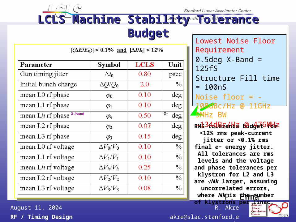
LCLS Machine Stability Tolerance BudgetLCLS Machine Stability Tolerance Budget
X-bandX-band XX--
RMS tolerance budget for <12% rms peak-current jitter or
<0.1% rms final e− energy jitter. All tolerances are rms levels and the voltage and
phase tolerances per klystron for L2 and L3 are Nk larger,
assuming uncorrelated errors, where Nk is the number of
klystrons per linac.
P. Emma
Lowest Noise Floor Requirement 0.5deg X-Band = 125fSStructure Fill time = 100nSNoise floor = -108dBc/Hz @ 11GHz 5MHz BW-134dBc/Hz @ 476MHz
Page 3
R. Akre
RF / Timing Design [email protected]
August 11, 2004
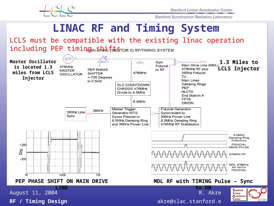
LINAC RF and Timing System
PEP PHASE SHIFT ON MAIN DRIVE LINE MDL RF with TIMING Pulse – Sync to DR
Master Oscillator is located 1.3 miles
from LCLS Injector
1.3 Miles to LCLS Injector
LCLS must be compatible with the existing linac operation including PEP timing shifts
Page 4
R. Akre
RF / Timing Design [email protected]
August 11, 2004
Linac Phase Reference SystemMain Drive Line - 3 1/8 Rigid Coax Anchored to Concrete Floor Every SectorPhase Reference Line - Each Sector Independent 1/2 “ HeliaxMust not introduce noise over 2 miles
Page 5
R. Akre
RF / Timing Design [email protected]
August 11, 2004
Linac Phase Reference SystemMain Drive LineMain Drive Line
3 1/8 inch Rigid Coax with 3 1/8 inch Rigid Coax with 30watts input power 30mW out30watts input power 30mW out
Length = 31 Sectors, 15.5 Length = 31 Sectors, 15.5 furlongs 2miles, 3km : Velocity = furlongs 2miles, 3km : Velocity = 0.98c0.98c
Anchored at each sector next to Anchored at each sector next to coupler and expansion jointcoupler and expansion joint
Purged with dry nitrogenPurged with dry nitrogen
Phase Length Range 100Phase Length Range 100S/YearS/Year
Phase Length Range 40Phase Length Range 40S/DayS/Day
Accuracy Based on SLC Fudge Accuracy Based on SLC Fudge FactorFactor
0.50.5S/Sector Total VariationS/Sector Total Variation
0.2S rms / Sector
Phase Reference LinePhase Reference Line
½ inch Heliax Cable with 1.2 Watts½ inch Heliax Cable with 1.2 Watts
Phase Reference for 8 PADs (Klystrons) Phase Reference for 8 PADs (Klystrons) in the sectorin the sector
Length = 1 Sector, 0.5 furlongs, 332ft, Length = 1 Sector, 0.5 furlongs, 332ft, 400k400kS in ½” HeliaxS in ½” Heliax
Temperature Coefficient 4ppm/Temperature Coefficient 4ppm/CC
Waveguide Water Waveguide Water T = 0.1T = 0.1C rmsC rms
85% of the cable is regulated to 0.185% of the cable is regulated to 0.1C C rmsrms
15% may see variations of 215% may see variations of 2C rmsC rms
Average Temperature Variation = 0.4Average Temperature Variation = 0.4C C rmsrms
= 0.64= 0.64S rmsS rms
Page 6
R. Akre
RF / Timing Design [email protected]
August 11, 2004
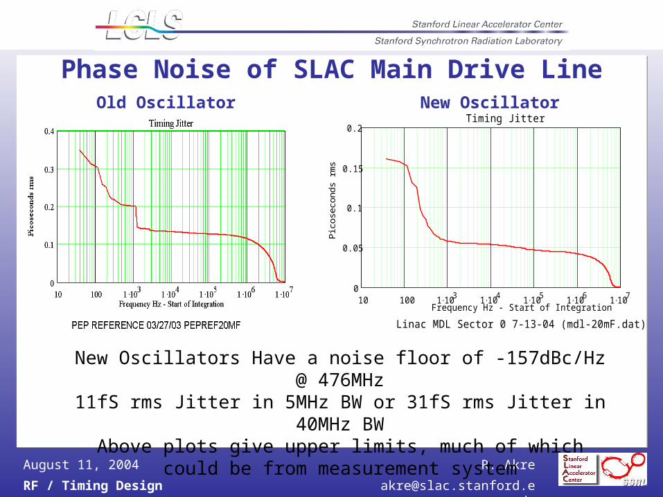
Phase Noise of SLAC Main Drive Line
Noise Floor -120dBc/38Hz = -136dBc/Hz = 120fS rms Jitter in 5MHz BW
Old Oscillator New Oscillator
New Oscillators Have a noise floor of -157dBc/Hz @ 476MHz11fS rms Jitter in 5MHz BW or 31fS rms Jitter in 40MHz BWAbove plots give upper limits, much of which could be from measurement system
Noise Floor -133dBc/38Hz = -149dBc/Hz < 60fS rms Jitter in 5MHz BW
Page 7
R. Akre
RF / Timing Design [email protected]
August 11, 2004
Phase Noise of SLAC Main Drive Line
New Oscillators Have a noise floor of -157dBc/Hz @ 476MHz11fS rms Jitter in 5MHz BW or 31fS rms Jitter in 40MHz BWAbove plots give upper limits, much of which could be from
measurement system
10 100 1 103
1 104
1 105
1 106
1 107
0
0.05
0.1
0.15
0.2Timing Jitter
Frequency Hz - Start of Integration
Pico
seco
nds
rms
Linac MDL Sector 0 7-13-04 (mdl-20mF.dat)
Old Oscillator New Oscillator
Page 8
R. Akre
RF / Timing Design [email protected]
August 11, 2004
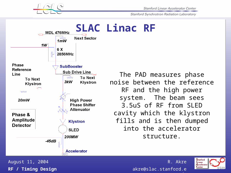
SLAC Linac RF
The PAD measures phase noise between the reference RF and the
high power system. The beam sees 3.5uS of RF from SLED cavity which the klystron fills and is then dumped
into the accelerator structure.
Page 9
R. Akre
RF / Timing Design [email protected]
August 11, 2004
LINAC RF MEETS ALL LCLS SPECIFICATIONSfor 2 Seconds when running well
Amplitude fast time plots show pulse to pulse variation at 30Hz. Standard deviation in percent of average amplitude over 2 seconds are 0.026% for 22-6 and 0.036% for 22-7.
Phase fast time plots show pulse to pulse variation at 30Hz. Standard deviation in degrees of 2856MHz over 2 seconds for the three stations are 0.037 for 22-6 and 0.057 for 22-7.
Page 10
R. Akre
RF / Timing Design [email protected]
August 11, 2004
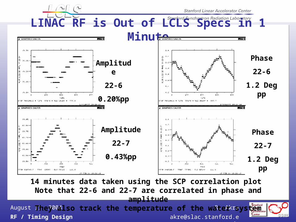
LINAC RF is Out of LCLS Specs in 1 Minute
14 minutes data taken using the SCP correlation plot Note that 22-6 and 22-7 are correlated in phase and amplitude
They also track the temperature of the water system
Amplitude
22-6
0.20%pp
Amplitude
22-7
0.43%pp
Phase
22-6
1.2 Deg pp
Phase
22-7
1.2 Deg pp
Page 11
R. Akre
RF / Timing Design [email protected]
August 11, 2004
Phase as Seen by Electron is Difficult to MeasureAccelerator Water Temperature Effects on SLED Phase[1]
The tuning angle of the SLED cavity goes as: = tan -1 (2QLT), Where T = L/L = -/QL= 17000 = 10-5 / F Thermal expansion of copper.
=tan -1 (0.34T) Where T is in F.For small T, (S)= 20T(F)
The relation between the tuning angle and the measured output phase of the klystron varies with the time after PSK with about the following relation:
/ = 0.35 just after PSK (S)= 7T(F) / = 0.50 800nS after PSK (S)= 10T(F)
/ T~ +8.5 S / F for SLED Cavity
Accelerator Water Temperature Effects on the Accelerator Phase[2]
The phase change of the structure goes as follows: = f Where = phase through structure
= Angular frequencyf = Filling time of structure
= f = / x f / = -L/L = -T = -10-5 T / F for copper
= -10-5 T / F22856MHz0.84S = -0.15 T rad/F = -8.6 T S / F
/ T = -8.6 S / F for Accelerator StructureWater / Accelerator Temperature Variation is 0.1F rms through structure is 0.86F rms
[1] Info from D. Farkas[2] Info from P. Wilson
Page 12
R. Akre
RF / Timing Design [email protected]
August 11, 2004
Phase as Seen by Electron is Difficult to Measure
Accelerator Water Temperature Effects on the Phase Through the Accelerator -8.6 S / F
SLAC Linac Accelerator Water Temperatures T< .08Frms
Phase Variations Input to Output of Accelerator > 0.5ºS-Band rms
Single Measurement Can’t Determine the Phase the Beam Sees Passing Through the Structure to LCLS Specifications
Feedback on Input Phase, Output Phase, Temperature, Beam Based Parameters (Energy and Bunch Length) is Required to Meet LCLS Specifications
Page 13
R. Akre
RF / Timing Design [email protected]
August 11, 2004
LINAC SECTOR 20 – LCLS INJECTOR
RF Stability < 50fS rms : Timing/Trigger Stability 30pS rmsUsing LASER as LCLS RF OSCILLATOR is UNDER CONCIDERATION
Page 14
R. Akre
RF / Timing Design [email protected]
August 11, 2004
LCLS RF System – Sector 20 Layout
100ft ½” Heliax = 0.3ºS/ºF
Tunnel Temperature < 0.1deg F rms
Page 15
R. Akre
RF / Timing Design [email protected]
August 11, 2004
SPPS Laser Phase Noise Measurement
R. Akre, A. CavalieriR. Akre, A. Cavalieri
Page 16
R. Akre
RF / Timing Design [email protected]
August 11, 2004
SPPS Laser Phase Noise Measurements
Phase Noise of Output of Oscillator with Respect to InputMeasurement done at 2856MHz with External Diode
Need to verify these results and check calibrationR. Akre, A. CavalieriR. Akre, A. Cavalieri
Page 17
R. Akre
RF / Timing Design [email protected]
August 11, 2004
SPPS Laser Amplitude of Phase Transfer FunctionSPPS Laser Oscillator Amplitude Transfer Function
-25.0
-20.0
-15.0
-10.0
-5.0
0.0
5.0
10.0
0 5000 10000 15000 20000 25000 30000 35000
Frequency Hz
Am
plitu
de
dB
Phase Modulation placed on RF Reference and measured on Diode at Laser output.
During the Blue part of the curve the modulation amplitude was reduced by 12dB to prevent laser from unlocking. Data taken 10/22/03 R. Akre, A. CavalieriR. Akre, A. Cavalieri
Page 18
R. Akre
RF / Timing Design [email protected]
August 11, 2004
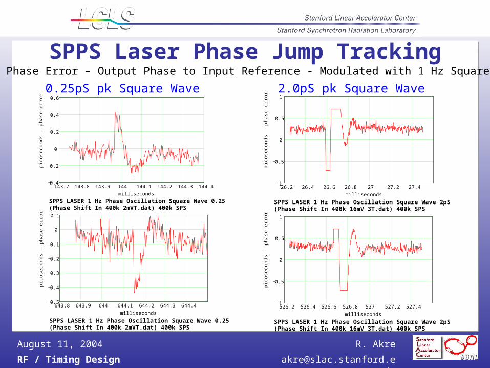
SPPS Laser Phase Jump Tracking
R. Akre, A. CavalieriR. Akre, A. Cavalieri
Page 19
R. Akre
RF / Timing Design [email protected]
August 11, 2004
SPPS Laser Phase Jump Trackingk1 0
kpts 12
143.7 143.8 143.9 144 144.1 144.2 144.3 144.40.4
0.2
0
0.2
0.4
0.6
milliseconds
pico
seco
nds
- ph
ase
erro
r
SPPS LASER 1 Hz Phase Oscillation Square Wave 0.25pS pk (Phase Shift In 400k 2mVT.dat) 400k SPS
k1 0kpts 1
2
643.8 643.9 644 644.1 644.2 644.3 644.40.5
0.4
0.3
0.2
0.1
0
0.1
milliseconds
pic
ose
cond
s -
ph
ase
err
or
SPPS LASER 1 Hz Phase Oscillation Square Wave 0.25pS pk (Phase Shift In 400k 2mVT.dat) 400k SPS
k1 0kpts 1
2
26.2 26.4 26.6 26.8 27 27.2 27.41
0.5
0
0.5
1
milliseconds
pic
ose
cond
s -
ph
ase
err
or
SPPS LASER 1 Hz Phase Oscillation Square Wave 2pS pk (Phase Shift In 400k 16mV 3T.dat) 400k SPS
k1 0kpts 1
2
526.2 526.4 526.6 526.8 527 527.2 527.41
0.5
0
0.5
1
milliseconds
pic
ose
cond
s -
ph
ase
err
or
SPPS LASER 1 Hz Phase Oscillation Square Wave 2pS pk (Phase Shift In 400k 16mV 3T.dat) 400k SPS
0.25pS pk Square Wave 2.0pS pk Square Wave
Laser Phase Error – Output Phase to Input Reference - Modulated with 1 Hz Square Wave
Page 20
R. Akre
RF / Timing Design [email protected]
August 11, 2004
Linac Phase Stability Estimate Based on Energy Linac Phase Stability Estimate Based on Energy Jitter in the ChicaneJitter in the Chicane
SLAC LinacSLAC Linac
1 GeV1 GeV 30 GeV30 GeV9 GeV9 GeV
ee Energy (MeV) Energy (MeV)
BPM
221/21/2< 0.1 deg (100 fs)< 0.1 deg (100 fs)
EE/E/E00 0.06% 0.06%
P. Emma
Page 21
R. Akre
RF / Timing Design [email protected]
August 11, 2004
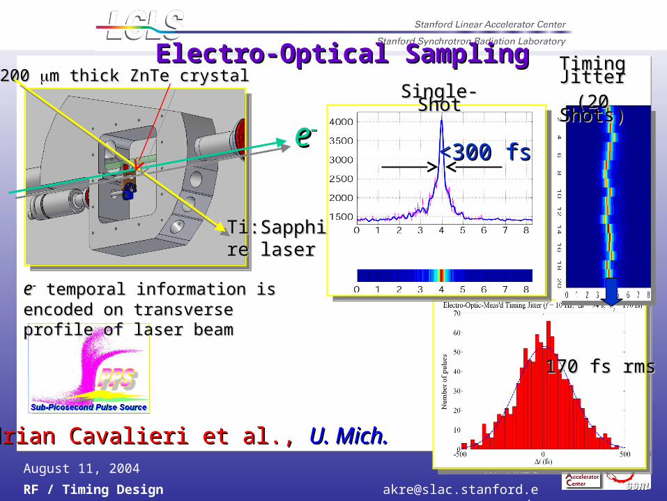
Electro-Optical SamplingElectro-Optical Sampling
170 fs rms170 fs rms
Single-ShotSingle-Shot
Timing JitterTiming Jitter(20 Shots)(20 Shots)
200 200 m thick ZnTe crystalm thick ZnTe crystal
ee
Ti:Sapphire Ti:Sapphire laserlaser
Adrian Cavalieri et al., Adrian Cavalieri et al., U. Mich.U. Mich.
<300 fs<300 fs
ee temporal information is encoded on temporal information is encoded on transverse profile of laser beamtransverse profile of laser beam
Page 22
R. Akre
RF / Timing Design [email protected]
August 11, 2004
LCLS Phase Noise Associated Time Referenced to Beam Time
LCLS Laser ~200uS Off Scale BelowLCLS Gun 1.1uS SLED / Accelerator 3.5uS Phase Detector (Existing) 30nSDistribution System 200nS
1km @ c-97%c=100nS
Far Hall Trigger 2uS3km @ c-80%c=2uS
TIME
-3.5us SLED Starts to Fill
-1.1uS Gun Starts to Fill
-2uS Far Hall TrigRF Starts Trip
Beam Time 0Reference
Except for the LASER common mode noise levels below ~100kHz would not cause instabilities – the entire system would track the deviations
Page 23
R. Akre
RF / Timing Design [email protected]
August 11, 2004
Beam Trigger for User Facility
Single Pulse with 30fS stability (1Hz to 3GHz BW)
Tightest Noise Tolerance of LCLS
Wide Bandwidth
Low Phase Noise 30fS Stability today
10fS Stability tomorrow
1fS The Day After
Currently users are expected to use local beam timing measurement, EO, to achieve this.
Page 24
R. Akre
RF / Timing Design [email protected]
August 11, 2004
FY04 Tasks
Complete phase measurement system
Complete measurements in the SLAC front end
Preliminary design for SLAC linac RF upgrade
Complete Design of 1kW Solid State S-Band Amp
Page 25
R. Akre
RF / Timing Design [email protected]
August 11, 2004
FY05 Tasks and ResourcesReady to Ramp Up
Start on X-Band systemComplete SLAC Linac Front End UpgradesComplete Design of Phase Reference SystemComplete Design of LLRF Control SystemDefine Beam Phase Cavity MonitorFurther Studies on Linac Stability
SLAC Klystron Department to Support 75% of RF manpower
Manpower available from other SLAC groups (ARDA, ARDB, NLC, and Controls) and LBNL