20
r Ball and Beam Ө = c*Input Voltage(u) Y = a*x System Equations State Space Model
| Date post: | 19-Dec-2015 |
| Category: |
Documents |
| Upload: | howard-manning |
| View: | 219 times |
| Download: | 1 times |

r
Ball and Beam
Ө = c*Input Voltage(u)Y = a*x
System EquationsState Space Model

Hardware Issues and Calibration
Wiring IssuesSharp Sensor Output IssuesPotentiometer IssuesMechanical Grip Issues

Final Calibration
Voltage = (-1.0442e-06)*distance^4 + 0.00012262*distance^3 -
0.0040194*distance^2 -0.0091906*distance + 2.8626
y = (4.3862e-07)*x^3 – (3.8462e-07)*x^2 – (0.0099189)*x + 2.2135

Control Strategy
Also employed the strategy of On-Off Controller

Modeling of DC Motor Position
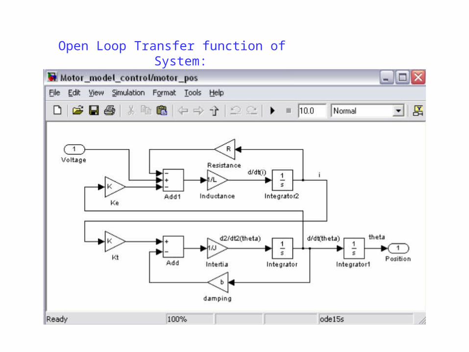
Open Loop Transfer function of System:
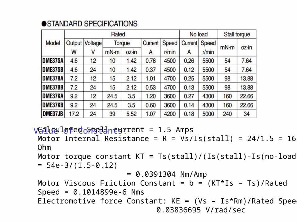
Calculated Stall current = 1.5 AmpsMotor Internal Resistance = R = Vs/Is(stall) = 24/1.5 = 16 OhmMotor torque constant KT = Ts(stall)/(Is(stall)-Is(no-load)) = 54e-3/(1.5-0.12)
= 0.0391304 Nm/AmpMotor Viscous Friction Constant = b = (KT*Is – Ts)/Rated Speed = 0.1014899e-6 NmsElectromotive force Constant: KE = (Vs – Is*Rm)/Rated Speed =
0.03836695 V/rad/sec
Value of Constants:

Linearized Model of DC Motor
(0.00037461*(z+0.99)*(z+5.843e-08))--------------------------------------------------(z*(z-1)*(z-0.9683))
Linearized Transfer Function:
Sample time: 0.001
Analysis: There is a pole and zero very near to z = 0 that effectively cancel. -> Makes computations simpler. So, now our transfer function becomes:
0.00037461 (z+0.99) ------------------- (z-1) (z-0.9683)

State VariablesMotor PositionMotor SpeedArmature Current
Input: Armature VoltageOutput: Rotational Position

DC Motor State Space Model

Step Response of Linearized Model of DC Motor

Dynamics of DC Motor:With command d2c(sys,'tustin'), we get Continuous-time zero/pole/gain model:
-9.5146e-07 (s+3.981e05) (s-2000) ---------------------------------
s (s+32.21)
Analysis: Zero at 3.98 e05 contributes very little to the response of the plant.
Step Closed LoopResponse without Compensation

Gain Margin = 38.6 dB(at 254 rad/s); Phase Margin = 57.6 deg (at 20 rad/s)Gain crossover frequency = 3 Hz. So a sampling period of 0.001 seconds (frequency of 1000 Hz) is significantly faster than the dynamics of the plant.

Rise time: ≤ 0.05 secSettling time: ≤ 0.25 secOvershoot: ≤ 5%No steady state ErrorBandwidth must be significantly larger than overall ball and beam system.
Design Requirement for DC Motor Controller:

Closed Loop for DC Motor
P=10; I = 2; D= 0.1; N = 100
20*(z-0.9501) ------------- (z-0.9)
Discretized PID Controller:

Overall Closed Loop Response of DC Motor with Controller

Mass of the ball = m= 0.121 kgRadius of the ball = R = 0.0111mGravitational acceleration = 9.8 m/s^2Length of the beam (on left side of pivot)= 0.357mBall's moment of inertia = J = (2/5)*M*(R^2) = 5.9634e-6 kg.m^2
Modeling of Ball and Beam Plant
Value of Constants:

Overall Closed Loop Ball and Beam
P=25; I = 1; D= 7; N = 100
725 z - 722.5 ------------- z - 0.9
Discretized PID Controller:

Rise time: 0.6613 secSettling time = 9 sec
Overshoot = 5%
Overall Closed Loop Ball and Beam Step Response

Product Information Sheet R2-1, Rotary Ball & Beam Experiment, Quanser Inc., Markham, ON, Canada.
R. Hirsch, Shandor Motion Systems, "Ball on Beam Instructional System," Shandor Motion Systems, 1999.
K. C. Craig, J. A. de Marchi, "Mechatronic System Design at Rensselaer," in 1995 International Conference on Recent Advances in Mechatronics, Istanbul, Turkey, August 14-16.
R. A. Pease, "What's All This Ball-On-Beam-Balancing Stuff, Anyhow," Electronic Design Analog Applications, p. 50-52, November 20, 1995.
G. J. Kenwood, "Modem control of the classic ball and beam problem," B.S. thesis, Massachusetts Institute of Technology, Cambridge, MA, 1982.
References


![“Furry friends” Пушистые друзья «Sounds» [Ө] [ә][ә] [t] [ v] [][]](https://static.documents.pub/doc/80x56/56649f4a5503460f94c6bda9/furry-friends-sounds-.jpg)


