P.O. Box 1574 Hurst, Texas 76053 USA Ph: (817) 571-4528 Fax: (817) 571-2317 www.robotics.com User Guide Revision B7 9/24/98 Copyright (c) 1998 Arrick Robotics All Rights Reserved DbY\_R_d Mobile Robot For Research and Education
Congratulations for purchasing the Trilobot mobile robot. This manual should answer all your questions. We suggest you read and understand all of it before using your new robot. If you're too excited to read the entire text, read the precautions section then go directly to the Quick Start Guide which will get you up and running in the shortest possible time. The Trilobot is designed to be used with a variety of computer equipment. The software provided is designed for use with IBM-style personal computers running under DOS. This manual assumes the user has full understanding of how to use their computer and operating system. Refer to the documentation for the computer for additional information.
1
About the Trilobot
The Trilobot mobile robot is designed for educators and experimenters interested in robotics, automatic guided vehicles, artificial life, artificial intelligence and other related topics. The Trilobot offers a sturdy platform with computer controlled drive wheels along with a host of sensors including ultrasonic ranging, digital compass and wheel encoders. Commands can be sent to the Trilobot's on-board controller from a personal computer using a serial RS-232 interface. The user can communicate via radio modems to a desk-top PC or simply use a cable. The user can then control the Trilobot using any terminal program or by using popular programming languages such as C, BASIC or Pascal. A simple character-oriented command structure makes programming quick and efficient. The Trilobot is a versatile system that can perform a variety of tasks. Here are just a few examples: � Education and training. � Research in artificial intelligence, A-life, etc. � Testing platform for navigation algorithms. � Simulation of planetary exploration. � Inter-office mail and message delivery. � Maze solving. � Contests. � Publicity.
Precautions
2
Failure to observe these precautions may result in loss of life, damage to property and/or damage to the Trilobot.
The following precautions must be taken to insure trouble free operation of the Trilobot mobile robot. The order that these precautions are listed does not indicate their importance. Failure to observe these precautions may result in loss of life, damage of property and/or damage to the Trilobot. � Never attach or remove cables while power is applied to the Trilobot. � Never use the Trilobot in areas near deep water such as swimming pools. � Never use the Trilobot in areas that could result in a fall such as lofts, stairways, hills. � Never replace the fuse or other parts with a different style or value. � Never allow cables to fall out or be broken by the Trilobot's motion. � Never control devices with the Trilobot that could be dangerous to life or property such as lawn mowers or high power lasers. � Never connect the Trilobot's controller to inappropriate equipment. � Never use the Trilobot in situations where a programming error or malfunctions could cause damage to property or life.
� Never exceed the specifications such as payload, incline, current drain, etc.
Quick Start Guide
This section is designed for those who just can't wait to get their Trilobot running. Follow the steps as outlined then, after having some fun, take some time to read the rest of this manual. Completely understanding your Trilobot is the key to getting maximum usefulness and performance. If you experience any trouble with the following steps, locate the associated section in the table of contents and read additional information.
3
Step 1 - Getting everything together
The Trilobot package includes the robot, software, accessories and this manual. Make sure you have everything and give us a call if something doesn't look right. Remove any packaging material that may be attached or lodged in the Trilobot. Save all packaging material.
Step 2 - Installing batteries
Remove the battery cable from the controller. Remove the battery holder by unscrewing two thumb screws. Install 8 D-cell batteries observing polarity labels. Mount the battery holder back onto the Trilobot and attach the cable.
Step 3 - Power on
Locate the 3 buttons on the top edge of the controller circuit board. Press the green button labeled “ON”. The green LED nearby should light. If it immediately goes off then the batteries are too low for operation. If a message concerning bent whiskers is displayed, follow the directions for fixing them. See the Troubleshooting section for details
The display’s top line should show “Main Menu”. Use the up and down arrows to scroll through the menu items which will be displayed on the bottom line. When the bottom line shows “Status Screen”, press the “Y” key to select it. This screen shows battery voltage, sonar distance, compass heading, light level, temperature, whisker status, PIR sensor status, etc. See the status screen section for more information.
Step 4 - Display the status screen
Step 5 - Use the IR remote control
Press “N” to return from to the main menu from the status screen. Use the up/down arrows to find “IR Remote Control” and press “Y” to select. This mode allows you to use the IR remote control to manually control the robot. See the IR Remote Control section of this manual to learn more.
Now that you're off and running, read through this manual to understand each aspect of the Trilobot. Experiment with as many of the features as possible. Visit our web site often for new ideas at http://www.robotics.com. Good luck, and enjoy the Trilobot.
Step 6 - Learn about the Trilobot
Feature List
4
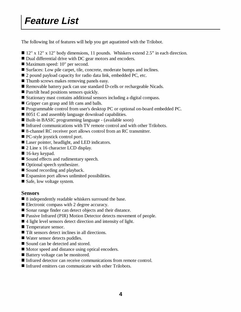
The following list of features will help you get aquatinted with the Trilobot. � 12" x 12" x 12" body dimensions, 11 pounds. Whiskers extend 2.5” in each direction. � Dual differential drive with DC gear motors and encoders. � Maximum speed: 10" per second. � Surfaces: Low pile carpet, tile, concrete, moderate bumps and inclines. � 2 pound payload capacity for radio data link, embedded PC, etc. � Thumb screws makes removing panels easy. � Removable battery pack can use standard D-cells or rechargeable Nicads. � Pan/tilt head positions sensors quickly. � Stationary mast contains additional sensors including a digital compass. � Gripper can grasp and lift cans and balls. � Programmable control from user's desktop PC or optional on-board embedded PC. � 8051 C and assembly language download capabilities. � Built-in BASIC programming language - (available soon) � Infrared communications with TV remote control and with other Trilobots. � 8-channel RC receiver port allows control from an RC transmitter. � PC-style joystick control port. � Laser pointer, headlight, and LED indicators. � 2 Line x 16 character LCD display. � 16-key keypad. � Sound effects and rudimentary speech. � Optional speech synthesizer. � Sound recording and playback. � Expansion port allows unlimited possibilities. � Safe, low voltage system. Sensors � 8 independently readable whiskers surround the base. � Electronic compass with 2 degree accuracy. � Sonar range finder can detect objects and their distance. � Passive Infrared (PIR) Motion Detector detects movement of people. � 4 light level sensors detect direction and intensity of light. � Temperature sensor. � Tilt sensors detect inclines in all directions. � Water sensor detects puddles. � Sound can be detected and stored. � Motor speed and distance using optical encoders. � Battery voltage can be monitored. � Infrared detector can receive communications from remote control. � Infrared emitters can communicate with other Trilobots.
Glossary of Terms
5
Analog Signals – Signals that have values between on and off (1 and 0). Android – A robot that has a human-like form. Artificial Intelligence (AI) – A computer program that simulates intelligence like that found in biological systems. Artificial Life – Behavior that is simulated by a computer program or other machine that mimics some or all aspects of biological life. Baud Rate – The number of bits per second. In a serial signal from a typical personal computer, the baud rate is the number of bytes per second times 10. Each byte consists of 8 data bits, 1 start bit, and 1 stop bit. BASIC – A high-level programming language. Binary – A numbering system using 2 numbers – 1 and 0. Bit – Abbreviation for binary digit. Each bit can have a value of 1 or 0. Byte – A group of 8 bits. C – A high-level programming language. Cellular Automata – A system constructed with an array of cells where each cell can act according to preset instructions and can respond to nearby cells. Once started the system proceeds without further instructions. Central Processing Unit (CPU) - The central component of a computer that executes instructions written by a programmer and controls I/O devices and memory. Chaos – Disorder displayed by some complex systems. Closed Loop – In motor control, the use of a feedback device such as an encoder to adjust the motor driver to achieve the desired position, speed, or acceleration. The Trilobot’s drive motors are closed loop. Compiler – A program that converts a high-level program into a low-level program that can be executed directly by a CPU. Digital Signals – Signals that can have a value of on or off (1 or 0). Encoder – A feedback device used by a motor to sense position and speed. Normally a wheel with holes or slots that are detected with an optical sensor. EEPROM – Electrically Erasable Programmable Read Only Memory. A type of memory IC that can be written and read, and will retain data even after power is turned off. Used by the Trilobot to store parameters. EPROM – Erasable Programmable Read Only Memory. A type of memory that can be read only, and retains its data after power is turned off. The Trilobot’s system program is stored in EPROM. Emergent Behavior – Unexpected behavior in a robot that was not explicitly programmed. Expert System – An intelligent system based on a database of rules. Feedback – A signal produced by a sensor such as an encoder that is used to adjust motor position and/or speed. Finite State Machine (FSM) – A machine or program that has a limited number of states, can examine its own states, can change its own state according to a set of rules, and can receive input from external sources. Firmware – Programs that are stored on EPROM such as the Trilobot’s system program.
Glossary of Terms Continued Fractals – A geometric pattern in which an object looks the same regardless of the viewing scale. Fractal concepts can be used in AI programming. Fuzzy Logic – Logic in which boundaries between sets are not crisp. This concept is often used to control systems that would be too complex to model with traditional sequential programs. Genetic Algorithm – A set of instructions that mimic biological life by simulating genes, mutation, and other aspects of living systems. Gripper – A device that allows a robot to grasp objects. The Trilobot’s gripper can grasp objects and lift them up. Hardware – Physical circuitry including circuit boards, ICs (integrated circuits), transistors, etc. H-Bridge – An arrangement of 4 transistors in the shape of the letter ‘H’ used to control the direction of a DC motor. The Trilobot uses a single IC that contains 2 H-bridges to control the drive motors. Hexadecimal – Base 16 numbering system. Each digit is written as 0-9,A-B. Hexadecimal makes it easier to enter data and address values. Example of a hex byte is 4A, example of a hex word is A04F. High-Level Language – A computer programming language that allows the user to create complex programs using instructions that represent many simpler instructions. Infrared (IR) - Electromagnetic radiation generated by thermal agitation. IR is invisible to the human eye. The Trilobot uses IR to communicate to other robots and to accept commands from the IR remote control. Also see Passive Infrared Integrated Circuit (IC) - A device where many electrical components are built together as a single component. The Trilobot uses integrated circuits on it’s circuit boards to perform most functions. Interpreter – A computer language that converts instructions while the program is running. Unlike a compiler that first converts the program to machine code. Interpreters are normally slower than compilers. Joystick – A control device that employs a stick to achieve 2 axis control. The Trilobot’s joystick can be used to control direction and speed. Laws of Robotics - Three laws written by Isaac Asimov which prevent robots from intentionally harming humans and set other task priorities. � A robot may not injure a human being or, through inaction, allow a human being to come to harm � A robot must obey the orders given it by human beings except where such an order would conflict with the First Law. � A robot must protect its own existence as long as such protection does not not conflict with the First or Second Law. Light Emitting Diodes (LED) - Semiconductor that gives off light. Liquid Crystal Display (LCD) - A type of display that can be controlled electrically and uses minimal power. The Trilobot’s LCD is used to give alphanumeric messages to the user. Loops – In a computer program, the re-execution of instructions using control flow statements such as GOTO and WHILE. Low-Level Language – The set of instructions used directly by a CPU to perform operations. Often referred to as assembly language.
6
Glossary of Terms Continued Mechatronics – A combination of mechanical and electrical devices to create a system. Natural Language – Language used by humans to communication. Neural Network – A network of processing elements that are connected together to simulate the intelli-gence created by biological brains. Often used to perform pattern recognition. Open Loop – in motor control, the lack of a feedback device. Parallel Data – Data that is transmitted multiple bits at a time using multiple wires. Parameters – Values used to control functions. The Trilobot stores parameters in EEPROM. Passive Infrared (PIR) sensor - A type of sensing device that converts infrared energy into electrical signals. The Trilobot has a PIR sensor that is used to detect motion of living objects. PC/104 – Embedded computer system standard which has connectors with 104 pins. PC/104 modules are similar to cards found in desktop personal computers except that they stack together instead of plug-ging into a mother board. Complete computer systems can be created using PC/104 products. The Tri-lobot can be controlled with a PC/104 embedded computer. Printed Circuit Board (PCB) - A non-conductive board that is laminated with layers of copper to pro-vide electrical connections between components. The Trilobot contains several PCBs. Pulse Width Modulation (PWM) - In motor control, the use of electrical pulses of various widths to control the motor’s position and speed. In speech and sound creation, the use of various pulse widths to generate an analog signal by using a low-pass filter. RAM – Random Access Memory. Read/write memory. The Trilobot uses RAM for data and program storage. Remote Control – Control of a system at a distance. The Trilobot can be remotely controlled using the IR remote control or joystick. Resolution – In a motor control system, the smallest motion that a motor can make. Robot – Any device that operates automatically performing tasks like a human. Rule-based System – See Expert Systems. Sensor – A device that converts light, temperature, and other phenomena to electrical signals. Also re-ferred to as transducer. The Trilobot uses many different sensors to detect the environment. Serial Data – Data that is transmitted a signal bit at a time over one wire. Servo Motors RC, DC – DC (direct current) servo motors use encoder feedback to monitor speed and position such as the Trilobot’s drive motors. RC (remote control) servo motors are small servo systems that include motor, geartrain, feedback device, and controller in a small package intended for remote con-trol airplanes and cars. RC servos are used by the Trilobot to control the gripper and head movement. Software – Instructions used to direct operations on a CPU. Sonar – See Ultrasonic. Speech Synthesizer – An electronic device that generates human speech and sounds. Subsumption Architecture – A programming method designed by Rodney Brooks of MIT that allows various functions to subsume other functions based on a predefined priority scheme. Telepresence – Control of a robotic system at a different location. The operator may be provided feed-back using various sensors. Transistor – A silicon-based semiconductor device that can be used as an electrical switch or as an am-plifier. Ultrasonic – Sound waves with a frequency greater then humans can detect. The Trilobot uses ultra-sonic sound waves to find the distance to nearby objects. Whiskers – Hair-like, flexible wires used to detect walls and other objects. The Trilobot has 8 such whiskers to aid in navigation.
7
Component Locator Use the following diagrams to familiarize yourself with the Trilobot's various components.
8
Display
Keypad
Console Connector
Joystick Connector
Viewing Adjustment
Dip Switch
Power On/Off
RC receiver Connector
Motor Connector
Battery Connector
Powerful Output
Expansion Connector
Body Connector
Head/Mast Connector
Controller
Mast
Head
Battery Holder
Handle
Drive Wheels
Gripper
Whiskers
9
Side View
Mast
IR Communication Transmitter
Compass Green LED
Temperature Sensor
Light Level Sensor
Tilt Sensor
Red LED
Battery Holder
Drive Wheel
Drive Belt
Encoder Wheel
Speaker
Whisker Wires
Shoulder Button
Encoder Cover
IR Communications Receiver Microphone
Headlight
Laser Pointer
PIR Passive Infrared Motion Detector
Sonar Range Finder
Optional Video Camera
Head
Functional Block Diagram
10
The following block diagram show most of the Trilobot’s subsystems and their arrangement.
M A IN PR O C E SS O R - 803 2
64K EP R O M 32K R AM 2K EE PR O M
C O PR O C ES S O R #1C O PR O C ES S O R #2
BAT TE R Y VO LTA G ER E G U LATO R S
T ER M IN ALLC D /K E Y PAD
M O TO RD R IV ER S
M O TO R SEN C O D E R S W H IS K ER S
C O N S O LEPO R T SH O LD E R
BU TTO N S
H E A D
M A ST
IR R E C EIV E R
IR T R A N SM IT TE R
SO N A RR A N G E F IN D ER
PIR M O TIO ND E TE C TO R
H E A D LIG H T
LA S ER
M IC R O P H O N E
ALT IT U D E M O TO RAZ IM U TH M O TO R
T ILT SE N S O R S
LIG H T S E N SO R S
T EM P ER AT U R E S E N SO R
R E D /GR E EN L E D S
C O M PA S S
AU D IOAM PLIF IE R
SP EA K E R
JO Y S TIC KPO R T
W ATE RSE N SO R
G R IPP ER
LIFT M O TO R
G R AS P M O TO R
G R AS P S W ITC H
D IPSW ITC H
EX PA N S IO NPO R T
The Trilobot Controller
The Trilobot controller consists of a single circuit board that controls all functions of the basic robot. including drive motors, gripper motors, head motors, compass sensor, light sensors, whiskers, ultrasonic range finder, tilt sensors, battery status sensor, audio in/out, IR in/out, temperature sensor, and the user-defined input/output signals. Arrangement There is one main controller CPU which has external program memory, and two CPU’s that are used as intelligent coprocessors. The coprocessors perform motor control and other time consuming tasks. See the functional block diagram for additional information. Mechanical The controller is mounted on a panel that can be removed with thumbscrews. This allows access to the cargo bay. The back side of the panel has mounting holes for the speech synthesizer and for a PC/104 stack. PC/104 is the specification for an industry standard embedded computer system. Removal of the Trilobot’s controller can be accomplished by removing the screws from the mounting panel side. Do not remove the screws from the component side of the controller card. Command Mode Programming Commands used to control the robot and request information consist of simple, ASCII characters which can be sent by a program or manually using a communications program such as Procomm. Any programming language that can communicate using the serial RS-232 port can be used to control the Trilobot. Commands are sent to the controller using "standard" RS-232 signals carried on a serial cable having a 9-pin D-sub style connector. Memory The main CPU is an Intel 80C32 microcontroller. This processor has a 64k section of program space which is read only, and a 64k section of data space which is read/write. The Trilobot’s system program resides in the top 32k of the 64k EPROM in program space. The bottom 32k of EPROM contains interrupt vectors and data for speech. This bottom section can be overwritten with a user program at the expense of speech. Calls can be made to the utility routines in the upper 32k of the EPROM. An EPROM programmer would be required for this. Special circuitry is used to place the 32k of RAM into the bottom 32k of program space normally occupied by EPROM. This allows the user to download a program into the RAM then swap it into program space for execution. Data in the lower 32k of EPROM will not be accessible. The RAM will simultaneously appear in program space and data space so it can also be used to store variables in areas where the program does not exist. It is necessary to copy the interrupt vectors from EPROM to RAM before switching RAM into program space to allow interrupts to work. The RAM is backed up using a battery and will be retained when power is removed. Setting the startup parameter from the OPTIONS menu will allow these custom programs to be run automatically upon power up or reset. A 2k non-volatile EEPROM chip is also available for storage of parameters.
11
12
Upon power up or reset, the Trilobot’s operating system software which resides in the top 32k of EPROM assumes control of the robot’s systems. The following list outlines the sequence of events that occur: � All hardware is initialized. � Parameters are loaded from EEPROM, If the “Y” button is depressed, EEPROM defaults will be set. � If the “N” button is depressed, Terminal mode will be activated even if the startup code is different. � Reset count is incremented. � Head and gripper servo motors are initialized. � Startup sound effect or speech is performed. � Startup message sent to terminal LCD. � Battery status is tested and a message given if low. � Whiskers are checked and a message given active. � The operating mode is activated based on startup code in EEPROM. Operating modes The default startup mode is terminal mode. Other modes can be selected from terminal mode or the startup parameter can be set to automatically activate any mode desired. Terminal mode Allows the user to manually test various sensors and functions, activate programs, and select other oper-ating modes using the keypad and LCD. Console command mode Accepts commands from the console command port and allows the robot to be controlled from external computers via high-level languages. The robot’s controller simply becomes a slave of the master com-puter giving the commands. All robot functions are accessible. IR control mode This mode allows the user to control the Trilobot using the IR (Infrared) remote control. Drive wheels, head movement, gripper functions, and speech can be controlled. Joystick control mode The joystick can be used to control the robot’s motion, head movement, and gripper action. TriloGuard Mode This mode causes the Trilobot to watch for moving, living objects using the PIR sensor and respond to them. In this mode, the Trilobot could be set in a doorway and used to greet those who walk by. TriloWander In this mode, the Trilobot will wander around and attempt to avoid obstacles using the sonar range finder and the whiskers. This mode can be used as a general demonstration.
Operating System
Removable Body Panels
13
Thumbscrews are used to attach the controller panel, an accessory panel, battery holder, and the top panel that the head is mounted to. This allows quick removal of the panels. Additional holes are pro-vided to allow panels to be moved to different places. The accessory panel in the cargo bay area can be moved to various locations or removed all together to provide more room. Do not over tighten the thumbscrews and insure that they are inserted straight to prevent cross threading.
Thumbscrew
Side View
Operation
Power and Reset Buttons
14
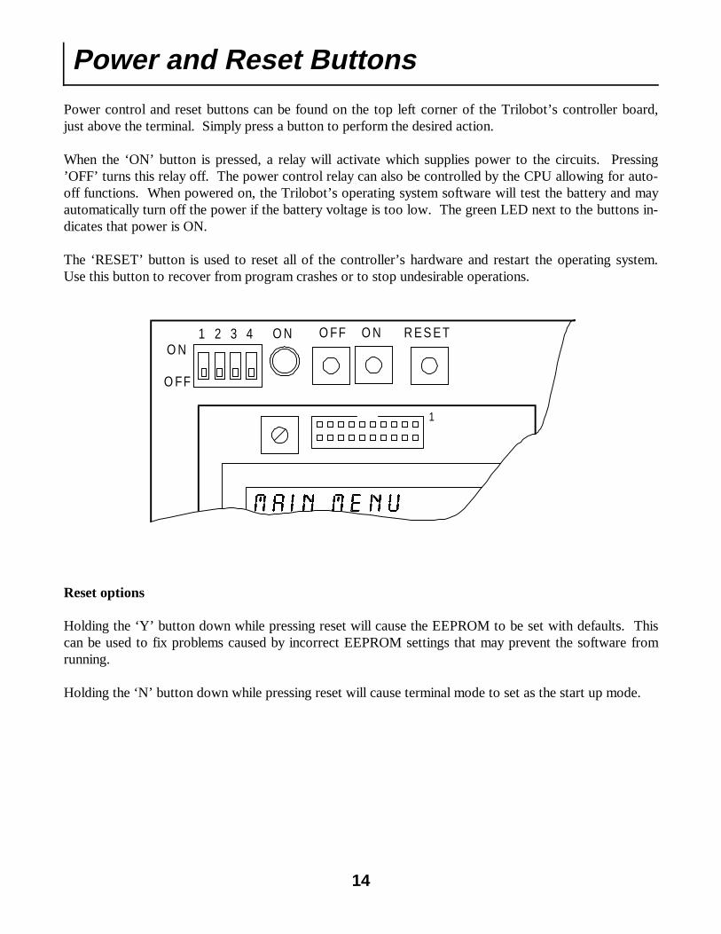
Power control and reset buttons can be found on the top left corner of the Trilobot’s controller board, just above the terminal. Simply press a button to perform the desired action. When the ‘ON’ button is pressed, a relay will activate which supplies power to the circuits. Pressing ’OFF’ turns this relay off. The power control relay can also be controlled by the CPU allowing for auto-off functions. When powered on, the Trilobot’s operating system software will test the battery and may automatically turn off the power if the battery voltage is too low. The green LED next to the buttons in-dicates that power is ON. The ‘RESET’ button is used to reset all of the controller’s hardware and restart the operating system. Use this button to recover from program crashes or to stop undesirable operations.
0DLQ 0HQX
1
1 2 3 4O N
O FF
O N O NO FF R ES ET
Reset options Holding the ‘Y’ button down while pressing reset will cause the EEPROM to be set with defaults. This can be used to fix problems caused by incorrect EEPROM settings that may prevent the software from running. Holding the ‘N’ button down while pressing reset will cause terminal mode to set as the start up mode.
Terminal Usage
15
Mounted on top of the Trilobot’s controller is a circuit board that contains an LCD (Liquid Crystal Dis-play) and keypad. This is called the Terminal and is the primary method for user interfacing. After powering on or reset, the Trilobot’s operating system will take control. If Terminal mode is se-lected as the startup mode then a menu will appear on the LCD. At that time the operator can navigate through the menus and control the robot, test functions, set parameters, etc. An adjustment screw is provided to optimize the LCD for viewing. Simply turn the screw until the best view is achieved. A 16-key keypad is provided for operator entry of values and for menu navigation. The ‘Y’ key is used to indicate ‘YES’, ‘ENTER’ and ‘SELECT‘. The ‘N’ key is used for ‘NO’ and ‘QUIT’. Up and down arrow keys are used to scroll up and down menu items. When entering decimal values, simply enter the value using the number keys, then press ‘Y’ to enter. When enter hexadecimal values, enter the value using the number keys and the other keys using their secondary meaning as shown below. Leading zeros must be entered when entering hexadecimal values. The hexadecimal value will be considered entered when the final digit is pressed. The LCD displays 2 lines, each with 16 alpha-numeric characters. When navigating menus, the top line shows the menu name and the bottom line shows the menu item. Use the up and down arrows to move to the desired item, then press ‘Y’ to select that item. Most functions can be stopped by pressing ‘N’. It may be necessary to keep the ‘N’ pressed for some time to escape some functions.
0DLQ 0HQX
7HVW
�
� � � � �
� � � � 1 <
� �
�
�
1
View ingAd justm ent
Connector
LC D -Liquid C rysta l D isplay16 characters x 2 lines
Keypad A B C
D E F
Hexadecim al valuescan be en teredusing these keys
Use UP and DO W N arrowkeys to scro ll through m enuitem s.
To use m enu, top lineis m enu title , bottomline is the m enu itemto be se lec ted.
‘N ’ key used for ‘N O’and to quit functions.
‘Y ’ key used for ‘YE S’and E NTE R .
Main Menu
16
The main menu allows the operator to scroll through the top-level selections of the menu system. You ‘ll have the following choices: Help – Gives a brief explanation of terminal usage. Test Menu– The test menu allows you to select any Trilobot function and test or exercise it. This can give the user a good understanding of each Trilobot sensor and actuator. Status Screen – Shows battery voltage, compass heading, whisker status, PIR status, Sonar distance and other important information on a real time bases. This option can be used to test various functions or to simply experiment. Joystick Control – This mode allows the user to control the Trilobot using the Joystick. Drive wheels, head movement, and gripper functions can be controlled. IR Control – This mode allows the user to control the Trilobot using the IR (Infrared) remote control. Drive wheels, head movement, gripper functions, and speech can be controlled. TriloGuard Mode – This mode causes the Trilobot to watch for moving, living objects using the PIR sensor and respond to them. In this mode, the Trilobot could be set in a doorway and used to greet those who walk by. TriloWander – In this mode, the Trilobot will wander around and attempt to avoid obstacles using the sonar range finder and the whiskers. This mode can be used as a general demonstration. Set Options Menu – This leads to another menu that offers options such as the setting of joystick limits, gripper positions, head positions, console port baud rate, startup mode, sound control, etc. Console Command Mode – In command mode, the Trilobot accepts commands from the console serial port from a master control computer. This causes the Trilobot’s controller to act as a slave controller and is the most powerful method of high-level programming. Note: Your menu menus may differ if your Trilobot contains a different version of the operating system.
Status Screen
17
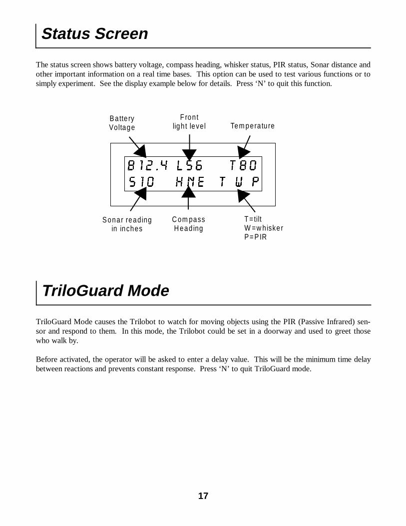
The status screen shows battery voltage, compass heading, whisker status, PIR status, Sonar distance and other important information on a real time bases. This option can be used to test various functions or to simply experiment. See the display example below for details. Press ‘N’ to quit this function.
%���� /�� 7��
6�� +QH 7 : 3
F ron tligh t level Tem pera tu re
Ba tte ryVoltage
Sonar readingin inches
C om passH ead ing
T =tiltW =w hiskerP= P IR
TriloGuard Mode
TriloGuard Mode causes the Trilobot to watch for moving objects using the PIR (Passive Infrared) sen-sor and respond to them. In this mode, the Trilobot could be set in a doorway and used to greet those who walk by. Before activated, the operator will be asked to enter a delay value. This will be the minimum time delay between reactions and prevents constant response. Press ‘N’ to quit TriloGuard mode.
TriloWander Mode
18
Start: ;Check battery. If battery low then Stop motion, Give speech message, Display message, Stop program. ;Whisker – Obstacle in front? If either front center whisker on then Move reverse 12”, Turn 180 degrees. ;Whisker – Obstacle left front? If front left whisker on and front right off then Move reverse 12”, Turn 15 degrees right. ;Whisker – Obstacle right front? If front right whisker on and front left off then Move reverse 12”, Turn 15 degrees left. ;Whisker – Obstacle right back? If back right whisker on and back left off then Move forward 12”, Turn 15 degrees left. ;Whisker – Obstacle left back? If back left whisker on and back right off then Move forward 12”, Turn 15 degrees right. ;Whisker – Obstacle in back? If both back whiskers on then Move forward 12” ;Whisker – Obstacle on left side? If side left whisker on then Turn 15 degrees right. ;Whisker – Obstacle on right side? If side right whisker on then Turn 15 degrees left. ;Sonar – Obstacle in center? If sonar center < 15” then Move reverse 12”, Turn 180 degrees. Move forward Go to start
In this mode, the Trilobot will wander around and attempt to avoid obstacles using the sonar range finder and the whiskers. This mode can be used as a general demonstration and as inspiration for new pro-grams. Press the red shoulder button for emergency stop. The TriloWander program can be described by the following pseudo-code:
Set Options Menu
19
This menu allows the operator to set various options and parameter values including: � Joystick limits and center � Head positions and speed � Gripper positions and speed � Console and Auxiliary port baud rate � Controller ID � Start up mode � Sound parameters These parameters and others are stored in non-volatile EEPROM and are set at the factory before ship-ment. The operator also has the ability to set default parameters in the event the EEPROM becomes cor-rupted by program errors. If the EEPROM is so corrupted that the system will not respond, you can set defaults by holding down the ’Y’ key on the keypad while pressing the reset button. Head Motors, Gripper Motors, and Joystick It may be necessary to set various parameters to compensate for replaced hardware such as the joystick or servo motors. Servo motors, which control the head and gripper movements, are not all exactly the same and must be calibrated. To set these options, which in effect calibrates them, simply select the ap-propriate menu item and follow the directions on the menu. The new values will be saved in EEPROM. Controller ID The Controller ID is the character that is used to identify the robot when using command mode program-ming. This is essentially the robots address. In the event that many robots are tied to the same serial data stream, it will be necessary to change this ID character for each robot. The default is ‘1’. Baud Rates Console and Auxiliary port baud rates can also be changed. The console port is used mainly for com-mand mode programming and the auxiliary port is used to attach accessories such as a speech synthe-sizer. When setting these options, you’ll be asked to enter a baud rate code. Codes are: 1=1200 baud, 2=2400, 3=4800, 4=9600. The default is 9600 baud. Startup Mode It is possible to change what the Trilobot does upon power up and reset using the Startup option. Use the following codes to set a startup mode: 0=terminal mode (Default), 1=console command mode, 3=joystick control, 4=RC control, 5=IR control, 6=Run user program from EPROM at specified ad-dress., 7=Run user program from RAM at specified address, 9=TriloGuard mode, 10=TriloWander. When selecting 6 or 7 you must also specify a program start address. Pressing the ‘N’ key while pressing reset will force terminal mode to be set. Sound and Speech Options for controlling the optional speech synthesizer, PWM speech or sound effects can also be se-lected. See the EEPROM Usage Listing and the OPTIONS menu for information about setting other parameters.
This mode allows the user to control the Trilobot using the Joystick. Drive wheels, head movement, and gripper functions can be controlled. Trim Controls Joysticks have trim controls for each axis that allows the user to adjust the center position of the joystick. When calibrating (see below) and using the joystick, set the trim controls to their center position. Buttons Joysticks have 2 or more buttons. Only 2 buttons are recognized by the Trilobot. When no buttons are being pressed, the joystick position will control the direction and speed of the Trilobot’s drive motors. If one button is pressed, the joystick position will control head movement, the other button allows control of the gripper. The exact style of the joystick you use will determine where these 2 buttons are located and how the stick responds. If your joystick has additional controls such as throttle and other buttons, they will not be recognized. The 2 joystick buttons are electrically the same as the shoulder buttons. Calibration If operation is erratic, it may be necessary to calibrate your joystick. Use the “Set Options” menu and se-lect ‘Joystick’. This procedure will set the center and limit positions of your particular joystick. Before calibration, make sure that the joystick’s trim controls are centered, and that the joystick is plugged in.
Joystick Control
20
IR Control Mode
21
This mode allows control of many Trilobot functions using the IR Remote Control. It may be necessary to point the IR remote control at the Trilobot’s head for a reading to be acknowledged. See the compo-nent locator page of this manual to see the location of the IR receiver. Most universal remote controls can be programmed to operate with various appliances. The remote con-trol should be programmed for use with a Philips TV/VCR. It may be necessary to try several different configurations. Press the red shoulder button for emergency stop. Note: Your Remote Control may differ from the one pictured.
Select VCR mode for proper operation
Turn right (press again to stop) Turn left (press again to stop) Nudge right Nudge left Forward (press again to stop) Reverse (press again to stop) ‘Yes’ head motion Head up ‘No’ head motion Head left Head center Head right Gripper control Head down Headlight control (On/Off) Speak ‘hello’ Speak ‘help’ Speak ‘ok’ Speak ‘ouch’ Speak ‘Please move’ * Speak ‘I am Trilobot’ * Stop motion
+ Volume – - Volume –
Fast Forward – Rewind –
Up Channel – Down Channel –
1 – 2 – 3 – 4 – 5 – 6 – 7 – 8 – 9 –
0 1 – 0 2 – 0 3 – 0 4 – 0 5 – 0 6 –
Stop –
* Speech requires optional speech synthesizer
Typical IR Remote Control
Programming
Command Mode Programming
22
Command mode allows the Trilobot to be controlled from an external computer through the console serial port. This external computer could be a desktop PC, a laptop, or an embedded PC located on the Trilobot. Any computer having a serial port can be used. Communication could be accomplished with a cable or by using a wireless data link. Control is performed by simply sending simple ASCII text commands to the Trilobot and receiving responses. The high-level program resides on the PC and can be written in BASIC, C, Pascal or virtually any other language that can communicate through the serial port. About Serial Ports On IBM-style personal computers, there are 4 possible serial (RS-232) ports referred to as COM ports. Their names are COM1, COM2, COM3 and COM4. Several devices require serial ports such as a mouse and modems. You must have one, unused serial port available to communicate with the Trilobot. Switch boxes are available that will allow you to share a single port with several devices. Serial port connectors come in two standard versions: a 9 pin male, and a 25 pin male. Other connectors on standard IBM-style personal computers that have the same number of pins but are female, are not normally serial ports. Some computers use different connector styles, check your computer’s manual for details including connector pinouts. About Programming Languages Almost any programming language allows access to the serial ports. QuickBasic, VisualBasic, C and Pascal are common languages that allow programming of the Trilobot. Some languages such as Microsoft QBasic, only allow access to COM1 and COM2. This could cause a problem if COM1 and COM2 are being used by a mouse and modem. In this case you could set up a switch box to access both an external modem or the Trilobot using a single COM port. Another solution is to install an additional serial port board and move the modem to COM3, leaving COM2 free. Commands Each command begins with “!“ followed by an ID character (Default “1”) which identifies the controller. The command itself consists of 2 or more characters. The first character normally indicates the type of command: G=Get (getting information from the Trilobot), P=Put (putting information to the Trilobot), O=Other commands. The command is then followed by any parameters required most of which are hexadecimal bytes (2 characters), or hexadecimal words (4 characters). All hexadecimal values must have leading zeros entered. Commands are not case sensitive. A command will either return an "A" indicating "accomplished" or will return the desired information. Commands and responses do not end with carriage returns or line feeds.
Sending Commands Manually
23
Begin by examining each command and its function. Experiment by sending commands manually using a terminal program such as Procomm which allows the operator to type on the keyboard and send those characters out to the serial port, any characters received by the serial port will be displayed on the screen. In Windows 95, Click the START button, then select RUN and type in “TERMINAL” or “HYPERTRM“. Use 9600 baud, 8 data bits, and 1 stop bit as the communication parameters. You’ll also need to know which com port is being used. Any system with an RS-232 serial port and a terminal program will be able to manually control the Trilobot in Command Mode. After attaching the cable, running a terminal program, and setting the parameters, try sending a command such as: !1GY1 Pressing ENTER or Carriage Return is not necessary. Upper and lower case characters will work. If everything is working correctly, your screen should display the Trilobot software version as 2 hex bytes (4 characters). If nothing is returned, double check the terminal program’s parameters, the Trilobot’s baud rate (see the “SET OPTIONS” section of this manual), and the console ID character which is “1” in the example above. Here are some more examples: !1GS2 This will return 3 hex bytes representing the sonar distance left, center and right. !1GW1 This will return a hex byte indicating the whisker status. !1GC2 This will return a hex byte indicating the compass heading. !1PG101 This will cause the gripper to lower and open. !1PG102 This will cause the gripper to close and lift !1PH104 This will cause the head to look left !1PH106 This will cause the head to look right !1PL03 This will turn the headlight on. !1PL02 This will turn the headlight off. !1PS81 This will speak “Hello”. You can then select a programming language and begin to send commands under program control.
Hexadecimal, Binary, Bytes, Words, etc.
24
Most commands require parameters in the form of hexadecimal values and many commands return hexa-decimal values. Sometimes the bits in these values will represent certain things. We’ll use the term “hex” to refer to hexadecimal. Bits A bit is a single binary (base 2) digit. Either a ‘1’ or a ‘0’. Digital computer such as the Trilobot’s, use binary values for processing. In some commands, the bits represented by a hex byte will indicate certain things. The GW – Get whisker command for instance, will return a hex byte in which each bit represents one of 8 whisker. A ‘1’ means that the whisker is active, a ‘0’ means it is inactive. When bits in a hex byte or word are identified by number, bit 0 is the right most (least significant) bit. Bit 7 is the left most (most significant) bit of a byte, and bit 15 is the left most (most significant) bit of a word. Bytes A byte consists of 8 bits. A byte can be represented in a hex value such as ‘00’ or ‘FF’. The range of values that a byte can represent is 0-255 decimal (00-FF hex). Words A word consists of 2 bytes (16 bits). A word can be represented in a hex value such as ‘0000’ or ‘FFFF’. The range of values that a word can represent is 0-65535 decimal (0000-FFFF hex). Hexadecimal Hex numbers are easy for computers to work with because each hex digit can represent 4 bits, 2 hex dig-its can represent a byte, and 4 hex digits can represent a word. Sometimes hex digits are referred to as nibbles. Hex numbers are base 16 instead of base 10 like our decimal numbering system. Hex digits are: 0 1 2 3 4 5 6 7 8 9 A B C D E F (16 total). The following table shows the binary equivalent for each hex digit:
Conversion With command mode programs it will be necessary to convert the hex bytes and words into their decimal equivalents. See the example program section where a sample routine is shown that performs this con-version.
Hex digit Binary value (bits) Decimal 8 1000 8 9 1001 9 A 1010 10 B 1011 11 C 1100 12 D 1101 13 E 1110 14 F 1111 15
Command Summary The Trilobot's controller receives commands constructed with simple characters. Each command begins with the 2-character prefix "!1" which identifies the controller. This arrangement allows multiple robots to be addressed independently if daisy-chained together using one serial RS-232 port. The command itself consists of 2 characters. The first character indicates the type of command: G=Get (get information from the robot), P=Put (put information to the robot), O = Other commands. The command is then followed by any parameters required. This scheme provides short command codes that are easy to remember. Characters can be in upper or lower case. Commands will either return an "A" indicating "accomplished" or will return the desired information. Most returned values are hex bytes (2 ASCII characters), or hex words (4 ASCII characters). Commands and responses do not end with carriage returns or line feeds. The following list describes each command.
25
GET commands GA1 Get aux serial port character !1GA1 Hex byte character. GB1 Get buttons, dip, grip switches !1GB1 Hex byte. Bits = switch status. GC1 Get compass heading !1GC1 Hex word heading 0-359. GC2 Get compass direction !1GC2 Hex byte direction code 0-7. GF1 Get temperature on mast !1GF1 Hex byte, temp in F. GH1 Get water sensor !1GH1 Hex byte, 0=false, 1=true. GI1 Get IR character !1GI1 Hex byte character. GJ1 Get Joystick position codes !1GJ1 Hex byte, 0-2=X, 3-5=Y,6,7= buttons. GJ2 Get raw joystick values !1GJ2 2 hex bytes - X, Y GK1 Get keypad character !1GK1 Hex byte character. GL1 Get light sensors !1GL1 4 hex bytes, Front, Right, Back, Left. GM1 Get drive motor distance !1GM1 Hex word indicating encoder counts. GM2 Get drive motor speed !1GM2 Hex byte indicating current speed. GP1 Get PIR status !1GP1 Hex byte, 0=false, 1=true. GQ1 Get sound level !1GQ1 Hex byte. 0-7. GR1 Get RC receiver !1GR1 8 hex bytes, channels 0-7. GS1 Get sonar distance !1GS1 Hex byte inches. GS2 Get sonar scan !1GS2 3 hex bytes, inches, left, center, right. GT1 Get tilt sensor !1GT1 Hex byte,bits 0-4=Front, Right, Back, Left. GU1 Get user digital port !1GU1 Hex byte. GU2 Get user analog port !1GU2 Hex byte. GV1 Get battery voltage !1GV1 2 hex bytes, whole volts, tenths. GW1 Get whisker status !1GW1 Hex byte, bits 0-7. GY1 Get CPU software version !1GY1 2 hex bytes, XX.XX GY2 Get coprocessor #1 version !1GY2 2 hex bytes, XX.XX GY3 Get coprocessor #2 version !1GY3 2 hex bytes, XX.XX GY4 Get reset count !1GY4 3 hex bytes. GZ1 Get CPU RAM data !1GZ1A010 1 hex byte from specified address. GZ2 Get EEPROM data !1GZ2A010 1 hex byte from specified address. GZ3 Get CPU Idata !1GZ3A010 1 hex byte from specified address. GZ4 Get CPU EPROM data !1GZ4A010 1 hex byte from specified address. GZ5 Get CPU Port 1 !1GZ5 1 hex byte. GZ6 Get CPU Port 3 !1GZ6 1 hex byte.
Code Description Example Returns
Commands continued
26
PUT commands PA1 Put aux serial port character !1PA13A Hex byte character to send. PD1 Put LCD character !1PD1003A Hex byte location, hex byte character. PE Put emergency stop !1PE01 Hex byte 1=on, 0=off. PG1 Put gripper control !1PG104 Hex byte control code. PH1 Put head motion control !1PH103 Hex byte control code. PI1 Put IR communications !1PI17F Hex byte character to send. PI2 Put IR communications !1PI27F Hex word IR code to send. PL Put light control !1PL02 Hex byte control code. PM Put drive motor control !1PM03002000 Speed byte, distance word, ratio byte. PN Put drive motor navigation !1PN01 Hex byte control code. PP Put powerful output !1PP01 Hex byte 0=off, 1=on. PR Put RC servo motor control !1PR017F 2 hex bytes, servo # 1-8, position 01-254. PS Put sound !1PS01 Hex byte code. PU Put user port control !1PU0301 2 hex bytes, bit # 0-7, state 0,1. PW Put auto-stop whisker mask !1PWFF Hex byte, 1 bit per whisker 1=stop, 0=ignore PZ Put hardware memory !1PZ0101FA88 Location code ,Address word, Data byte. Other commands OJ Jump to address !1OJ010080 Hex byte (RAM/EPROM), Hex word address. OM Mode change !1OM00 Hex byte mode control code. OC Coprocessor Communication !1OC None. Stopped by !@.
Code Description Example Parameters
Command Descriptions
Get Commands GA - Get Auxiliary Serial Port If parameter = 1 then waits for and returns a single character. Example: !1GA1 GB - Get Shoulder Buttons, Dip switches, and Gripper switches If parameter = 1 then returns shoulder buttons, dipswitch, gripper switches as hex byte. Each bit represents a switch, 0=off, 1=on. Bit 0=dip switch #1, bit 1=dip switch #2, bit 2=dip switch #3, bit 3=dip switch #4, bit 4=shoulder/joystick button #1, bit 5=shoulder/joystick button #2, bit 6=gripper switch #1, bit 7=gripper switch #2. Example: !1GB1 GC - Get Compass If parameter = 1 then returns heading as a hex word 0-359. If parameter = 2 then returns heading as hex byte 0-7 code (0=North, 1=NorthEast, 2=East, 3=SouthEast, 4=South, 5=SouthWest, 6=West, 7=NorthWest). Examples: !1GC1 (Get heading in degrees 0-359) !1GC2 (Get heading as a code 0-7) GF - Get Temperature in Degrees Fahrenheit If parameter = 1 then returns temperature in degrees F as hex byte. Example: !1GF1 GH - Get Water Sensor If parameter = 1 then returns wheel water sensor as hex byte. 0=false, 1=true. Example: !1GH1 GI - Get IR Communications If parameter = 1 then returns a translated character as a hex byte. If parameter = 2 then returns a binary IR code as a hex word. Example: !1GI1
27
In alphabetical order
28
GJ - Get Joystick A parameter of 1 indicates that the return value will be position codes and button status as a hex byte. Bit 0-2 = X axis position (0-7), bit 3-4 = Y axis position (0-7), bit 6 is button #1, bit 7 is button #2. A parameter of 2 returns the raw joystick positions as 2 hex bytes, X then Y, each as 0-99. Example: !1GJ1 GK - Get Keypad Entry If parameter = 1 then wait for and return a single character as a hex byte. Example: !1GK1 GL - Get Light Levels If parameter = 1 then returns light levels as 4 hex bytes. Front, right, back, left. Example: !1GL1 GM - Get Drive Motor Information If parameter = 1 then returns current drive motor distance as a hex word. Value is in encoder counts where 4 counts equals approximately one inch of travel distance. If parameter = 2 the returns current drive motor speed as a hex byte. Values range from 0-7. 0 indicates stopped. Example: !1GM1 GP - Get PIR Sensor If parameter = 1 then return PIR status as a hex byte, 0=false, 1=true.. Example: !1GP1 GQ - Get Sound Level If parameter = 1 then returns a hex byte indicating the sound level 0-7. Example: !1GQ1 GR - Get RC Receiver Values If parameter = 1 then returns 8 RC receiver channels as 8 hex bytes. Example: !1GR1 GS - Get Sonar (Ultrasonic) Range Finder If parameter = 1 then returns sonar distance in inches at the current head position. If parameter = 2 then returns 3 hex bytes each representing distance in inches: 15 degrees left, center, and 15 degrees right. The head will move to the appropriate position and leveled then a reading will be taken. Example: !1GS1
29
GT - Get Tilt Returns the value of all 4 tilt sensors as a single hex byte. Bit 0 = Front, bit 1 = Right, bit 2 = Back, bit 3 = Left. Example: !1GT1 GU - Get User Port If parameter = 1 then return user digital port as hex byte. If parameter = 2 then return user analog port as hex byte. Example: !1GU2 GV - Get Battery Voltage If parameter = 1 then returns 2 hex bytes. The first byte is whole volts, the second is tenths of volt. Example: !1GV1 GW - Get Whisker Status If parameter = 1 then returns status of 8 whiskers as a hex byte. Each bit represents a whisker status. 0=false, 1=true.. Example: !1GW1
GY - Get Software Version If parameter = 1 then returns 2 hex bytes indicating version number of system software as XX.XX. If pa-rameter = 2 then returns 2 hex bytes indicating version number of coprocessor #1 as XX.XX. If parame-ter = 3 then returns 2 hex bytes indicating version number of coprocessor #2 as XX.XX. If parameter = 4 then returns 3 hex bytes indicating reset count. Example: !1GY1
0 1 2 3
7 4
6 5
Whisker Bits (top view)
Bit 7 is most significant
Bit 0 is least significant
30
GZ - Get Hardware Information Returns a hex byte from the requested location. If parameter = 1 + hex word address then returns RAM data. If parameter = 2 + hex word address then returns SEEPROM data. If parameter = 3 + hex word address then returns Idata data. If parameter = 4 + hex word address then returns EPROM data (code space). If parameter = 5 then returns CPU port #1 as hex byte. If parameter = 6 then returns CPU port #3 as hex byte. Example: !1GZ101FA (RAM, Address=01FA) Put Commands PA - Put Auxiliary Serial Port Character Sends the specified character to the auxiliary serial port. One hex byte follows the command which is the character to send. Example: !1PA141 (41 hex is the letter ‘A’) Returns: “A” indicates acknowledged PD - Put LCD Sends the specified character to the LCD display at the specified location. Two hex bytes follow the command. The first hex byte is the location on the LCD, the second is the character. Using a location of 80 hex causes character to be placed at current location, 81 hex clears the screen first and places the char-acter at position 0. Positions 0-0f hex are the top line of the LCD, positions 40 hex – 4f hex are the sec-ond line. Example: !1PD14041 (40 is the 1st character of the second line, 41 hex is the letter ‘A’) Returns: “A” indicates acknowledged PE - Put Emergency Stop Enables or disables emergency stop switch. When enabled, the red shoulder button on the left size will stop all motion from drive motors and servo motors. Example: !1PE00 (Disaable emergency stop) Example: !1PE01 (Enable emergency stop) Returns: “A” indicates acknowledged
31
PG - Put Gripper Control A 1 then a hex byte follows the command and indicates the control code. 00=relax, 01=down&open, 02=close&up, 03=open, 04=close, 05=up, 06=down Example: !1PG101 (down and open) Returns: “A” indicates acknowledged PH - Put Head Motion Control A 1 then a hex byte follows the command and indicates the control code. 00=relax, 01=straight, 02=up&middle, 03=down&middle, 04=left&level, 05=far left&level, 06=right&level, 07=far right&level, 08=YES motion, 09=NO motion, 0A=Scan slow, 0B=far left, 0C=left, 0D=middle, 0E=right, 0F=far right, 10=up, 11=level, 12=down. Example: !1PH108 (Yes motion) Returns: “A” indicates acknowledged PI - Put IR Communications If the parameter = 1 then the following hex byte is an ASCII character that is translated to a binary IR code then transmitted. If the parameter = 2 then the following hex word is the binary IR code to send. Example: !1PI141 (41 hex is the letter ‘A’) Example: !1PI20020 (0020 is the binary IR code.) Returns: “A” indicates acknowledged, “0”=could not translate. PL - Put Light Control A hex byte follows the command and indicates the control code. 00=all lights off, 01=all lights on, 02=headlight off, 03=headlight on, 04=green LED off, 05=green LED on, 06=red LED off, 07=red LED on, 08=Laser off, 09=Laser on. Example: !1PL01 (All lights on) Returns: “A” indicates acknowledged PM - Put Drive Motor Control Following the command is a hex byte indicating the speed (00-07), a hex word (2 bytes) indicating the distance in encoder counts (0000-FFFF), then a hex byte indicating the ratio code. Ratio Codes: 00 Forward straight 01-0F Forward right at various arc radii 11-1F Forward left at various arc radii 20 Reverse straight 21-2F Reverse right at various arc radii 31-3F Reverse left at various arc radii 40 Spin right 41 Spin left Example: !1PM04008000 (Speed=04, Distance=0080, 00=Forward straight) Returns: “A” indicates acknowledged
Degree codes for rotate commands 00-3F
32
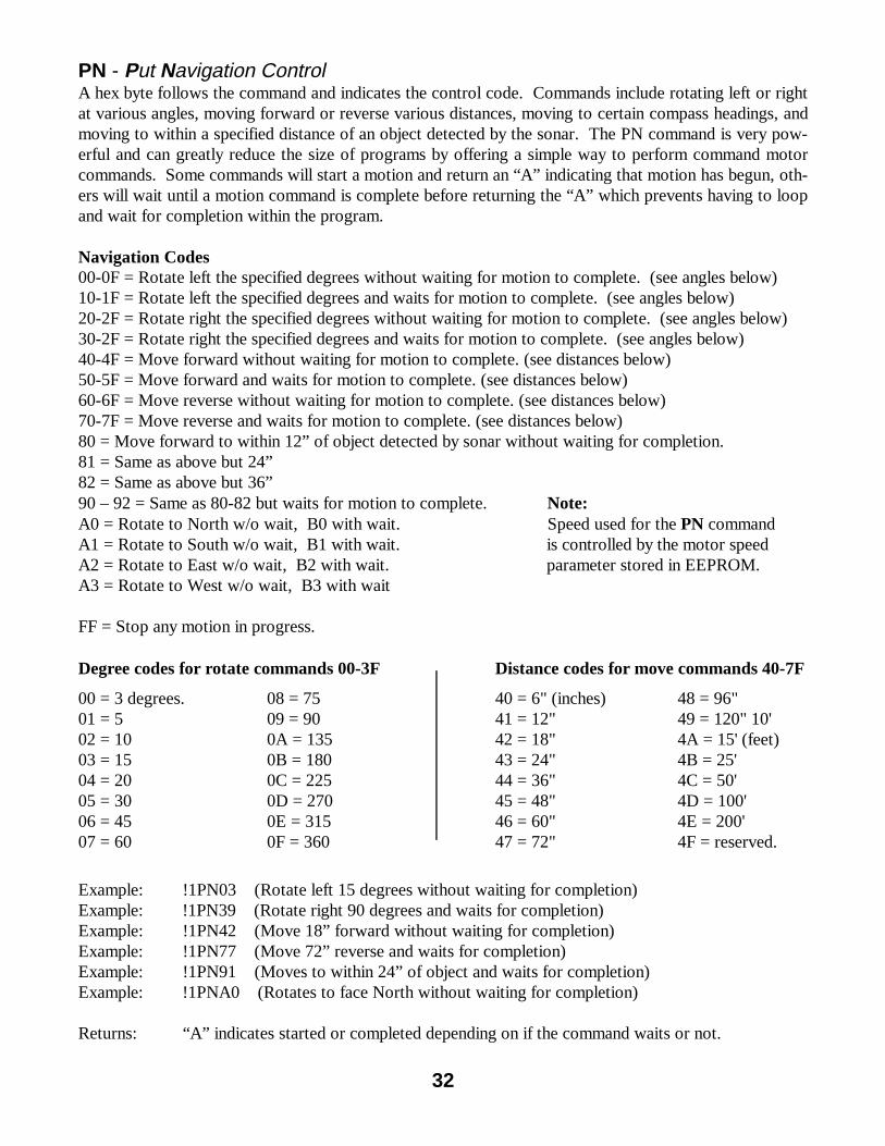
PN - Put Navigation Control A hex byte follows the command and indicates the control code. Commands include rotating left or right at various angles, moving forward or reverse various distances, moving to certain compass headings, and moving to within a specified distance of an object detected by the sonar. The PN command is very pow-erful and can greatly reduce the size of programs by offering a simple way to perform command motor commands. Some commands will start a motion and return an “A” indicating that motion has begun, oth-ers will wait until a motion command is complete before returning the “A” which prevents having to loop and wait for completion within the program. Navigation Codes 00-0F = Rotate left the specified degrees without waiting for motion to complete. (see angles below) 10-1F = Rotate left the specified degrees and waits for motion to complete. (see angles below) 20-2F = Rotate right the specified degrees without waiting for motion to complete. (see angles below) 30-2F = Rotate right the specified degrees and waits for motion to complete. (see angles below) 40-4F = Move forward without waiting for motion to complete. (see distances below) 50-5F = Move forward and waits for motion to complete. (see distances below) 60-6F = Move reverse without waiting for motion to complete. (see distances below) 70-7F = Move reverse and waits for motion to complete. (see distances below) 80 = Move forward to within 12” of object detected by sonar without waiting for completion. 81 = Same as above but 24” 82 = Same as above but 36” 90 – 92 = Same as 80-82 but waits for motion to complete. Note: A0 = Rotate to North w/o wait, B0 with wait. Speed used for the PN command A1 = Rotate to South w/o wait, B1 with wait. is controlled by the motor speed A2 = Rotate to East w/o wait, B2 with wait. parameter stored in EEPROM. A3 = Rotate to West w/o wait, B3 with wait FF = Stop any motion in progress.
Example: !1PN03 (Rotate left 15 degrees without waiting for completion) Example: !1PN39 (Rotate right 90 degrees and waits for completion) Example: !1PN42 (Move 18” forward without waiting for completion) Example: !1PN77 (Move 72” reverse and waits for completion) Example: !1PN91 (Moves to within 24” of object and waits for completion) Example: !1PNA0 (Rotates to face North without waiting for completion) Returns: “A” indicates started or completed depending on if the command waits or not.
PP - Put Powerful Output Control A hex byte follows the command and indicates the ON/OFF. 00=off, 01=on. Example: !1PP01 (Powerful Output on) Returns: “A” indicates acknowledged PR - Put RC Servo Motor Control Two hex bytes follow the command. The first byte indicates the servo # (01-08), the second byte indi-cates the position (01-FE). A position of 00 will cause the servo to relax. Servo Motor Numbers 01 Head Azimuth (Left/Right) 02 Head Altitude (Up/Down) 03 Gripper Up/Down 04 Gripper Open/Close 05 User servo motor #1 06 User servo motor #2 07 User servo motor #3 08 User servo motor #4 Example: !1PR0480 (Servo motor 4, position 80 hex) Returns: “A” indicates acknowledged PS - Put Sound Activates sound effects and speech. Hex byte code follows which indicated the sound. The sound con-trol parameter in EEPROM determines if the speech code uses PWM speech or the optional synthesizer.
08 = woop down sound 09 = woop up sound 0A = high/low 5 times 0B = Very short high tone 0C = Click FF = Nothing.
Example: !1PS09 (woop up) Returns: “A” indicates acknowledged PU - Put User I/O Port Two hex bytes follow the command. The first byte indicates the bit # 0-7, the second byte indicates the state 0=logic low, 1=logic high. Example: !1PU0300 (bit 3 off) Example: !1PU0701 (bit 7 on) Returns: “A” indicates acknowledged
Sound effect codes 00 = low tone 01 = high tone 02 = 2 high tones 03 = 3 high tones 04 = 4 high tones 05 = 5 high tones 06 = 6 high tones 07 = 7 high tones
Note: Servo motors may be energized or de-energized (relaxed). When energized, the motor will resist any change in position. When relaxed, external forces my move change the motor’s position. Relax motors when holding torque is not needed and to save power consumption.
34
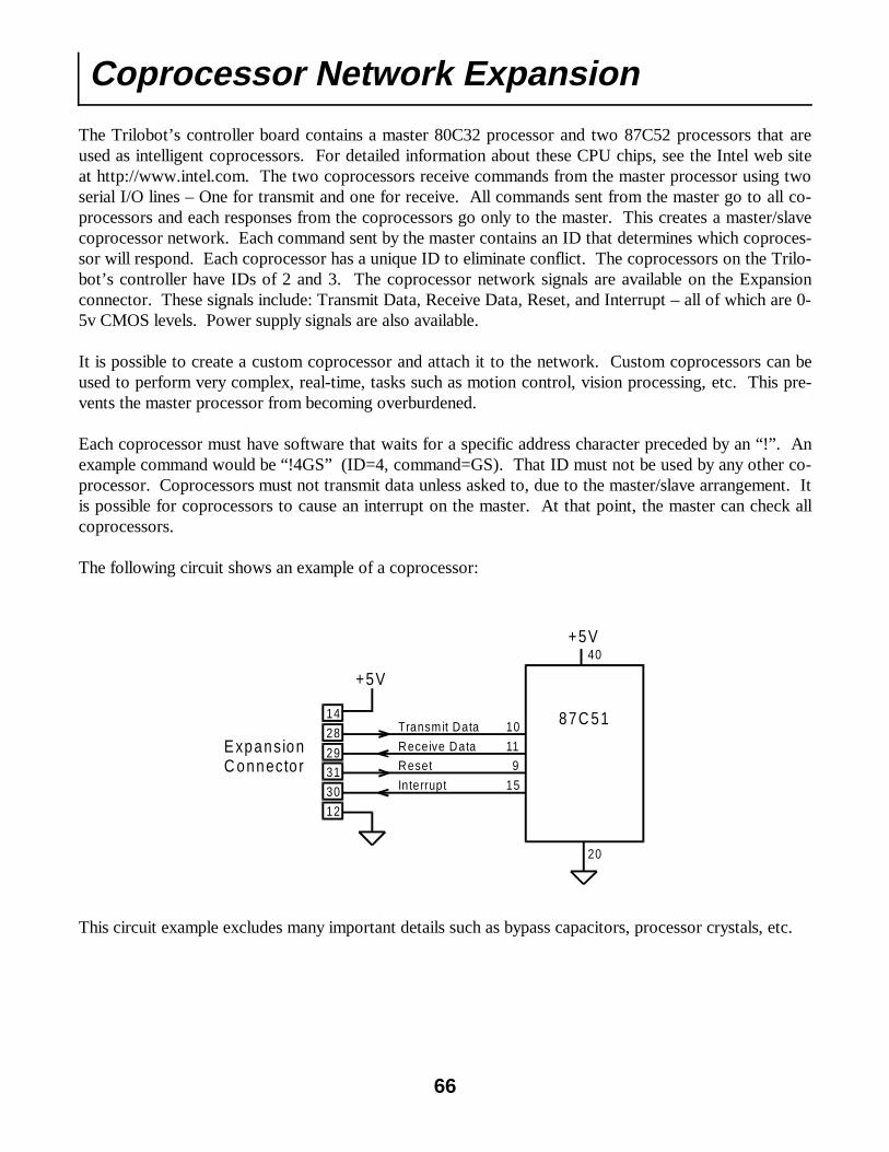
PW - Put Whisker Auto Stop Mask Causes drive motors to stop if specified whiskers become active. A hex byte follows the command and each bit represents a whisker. Bit 00=right front corner, bit 01=right center, bit 02=left center, bit 03=left front corner, bit 04=left side, bit 05=left back corner, bit 06=right back corner, bit 07=right side. Example: !1PWFF (Set all whiskers active) Example: !1PW0F (Set front whiskers active) Example: !1PW00 (De-activate auto stop) Returns: “A” indicates acknowledged PZ - Put Hardware Memory and I/O Port Four hex bytes follow the command. The first byte is the location (1=RAM, 2=SEEPROM, 3=IDATA), the second and third byte is the 16 bit address (0000-FFFF), the last byte is the data to put. Example: !1PZ0101FA88 (RAM, Address=01FA, Data=88) Returns: “A” indicates acknowledged Other Commands OJ - Other, Jump to Specified Address Causes program control to jump to the specified address. Useful to jump to user programs. A RET (Return) instruction will return to command mode. First hex byte determines RAM (01) or EPROM (02). Address is specified in a hex word that follows. When RAM is specified, interrupt vectors are first copied from EPROM to RAM, then RAM placed in code space, then jumped to. Example: !1OJ010100 (Jump to 0100h in EPROM) Example: !1OJ020100 (Jump to 0100h in RAM) Returns: Nothing OM - Other, Mode Change Restarts the system software in the specified mode. A code follows as a hex byte that specifies the mode. Code: 00=terminal mode. 01=console command mode, 02=console menu mode, 03=joystick control mode, 04=RC receiver control mode, 05=IR control mode, 06=run from EPROM at following address, 07=run from RAM at following address, 09=TriloGuard mode, 0A=Wander mode. Example: !1OM00 (Terminal mode) Example: !1OM05 (IR control mode) Returns: Nothing OC - Other, Coprocessor Communication Allows the programmer to send commands to the coprocessor network. Useful to directly access exist-ing coprocessors, or to communicate with custom coprocessors through the expansion connector. After the OC command is received, all subsequent characters are sent to the network. Communication is stopped when a !@ is received. Example: !1OC!4GC!@ (Send !4GC to the coprocessor network.) Returns: any character from any coprocessor.
A 2k EEPROM is available to the master processor for storage of parameters. Normally these locations are not accessed by a custom program but we have listed here the pre-defined locations to satisfy your curiosity. It is safe to use the unused locations of the EEPROM (preferably near the top) for user pro-grams. Future versions of the Trilobot’s operating system may use more locations. The addresses are in hexadecimal. To modify or view these values in EEPROM, select UTILITIES from the main menu, then select EDIT MEMORY, then select EEPROM, and enter a 4-digit hexadecimal address. Addr Use 0 Controller ID character for command mode 1 Console baud rate, 0=300, 1=1200, 2=2400, 3=4800, 4=9600, 5=19200 2 Aux serial port baud rate, 0=300, 1=1200, 2=2400, 3=4800, 4=9600, 5=19200 3 Sound control. 0=off, 1=PWM speech, 2=Speech synthesizer. 4 reserved 5 Speech synthesizer voice #0-7 default=7 6 Startup sound # (default 9) 7 Keyclick sound # (default 11) 8 Battery low threshold. (any voltage above this value is OK) value=(voltage/6)*50, voltage=value*6*.02 so, 108=13v 100=12v, 91-11v, 83=10v, 75-9v, 69=8v, 58=7v, 50=6v 9 Battery Very low threshold (Time to panic) a Battery too low threshold (not enough to do anything but die) b Startup Mode – 0=terminal mode. (default), 1=console command mode, 2=console menu mode. 3=joystick control mode, 4=RC receiver control mode, 5=IR control mode, 6=run from EPROM at following address, 7=run from RAM at following address, 9=TriloGuard mode, 10=Wander mode. 11=test mode. c Run address high byte. Used by mode 6 and 7 above. d Run address low byte e Heartbeat interrupt 1=on, 0=off. f-13 Characters indicating uninitialized EEPROM. "12345" ASCII string Defaults put in EEPROM if that string not found here 14-64 Startup speech synthesizer string. 80 characters sent to auxiliary serial port Ending in 0. Put 0 at location 20 for no output Only sent if "speak flag" = 1 65 Year built (98=1998, 255=2155). Not year 2156 compliant. 66 Month built.
EEPROM Usage
35
36
EEPROM Usage Continued 67 Reset count high byte 68 Reset count medium byte 69 Reset count low byte 6a Password high byte * 6b Password low byte * 6c 360 degree rotate distance 6d Motor speed (default 3) 6e Head azimuth servo far left position (default 50) 6f Head azimuth servo middle position (default 125) 70 Head azimuth servo far right position (default 200) 71 Head alt servo far up position (default 100) 72 Head alt servo middle (straight) position (default 125) 73 Head alt servo far down position (default 150) 74 Head servo speeds 75 Gripper servo full close position (default 100) 76 Gripper servo full open position (default 150) 77 Gripper servo full up position (default 100) 78 Gripper servo full down position (default 150) 79 Gripper servo speeds 7a Joystick X lower limit 7b Joystick X center 7c Joystick X high limit 7d Joystick Y lower limit 7e Joystick Y center 7f Joystick Y high limit * Not currently implemented.
Example Programs The following example programs are written using QBasic which is supplied with most versions of DOS. It may be necessary to modify these programs for them to work correctly on you computer. If your COM port is 2, simply change the "COM1:" in the OPEN statement to "COM2:". On most systems, the following command entered at the DOS prompt will load example program #1 from the A: disk drive - QBASIC A:EXAMPLE1.BAS Then select START from the RUN menu to execute the program. Make sure that the Trilobot is in Com-mand Mode. Note: See our web site at http://www.robotics.com/trilobot/programs.html for the latest programs available. Conversion Routines The following subroutines need to be added to the end of each of the example programs. Most results returned by the Trilobot are hexadecimal bytes or words. These subroutines convert the hexadecimal bytes and words into decimal. ‘Convert a hexadecimal word in R0$ to decimal in R0 WORDTODEC: R1$=MID$(R0$,1,1) GOSUB NIBTODEC R0=R1*4096 R1$=MID$(R0$,2,1) GOSUB NIBTODEC R0=R0+(R1*256) R1$=MID$(R0$,3,1) GOSUB NIBTODEC R0=R0+(R1*16) R1$=MID$(R0$,4,1) GOSUB NIBTODEC R0=R0+R1 RETURN ‘Convert a hexadecimal byte in R0$ to decimal in R0 BYTETODEC: R1$=MID$(R0$,1,1) GOSUB NIBTODEC R0=R1*16 R1$=MID$(R0$,2,1) GOSUB NIBTODEC R0=R0+R1 RETURN ‘Convert a hexadecimal nibble in R1$ to decimal in R1 ‘This routine used by BYTETODEC AND WORDTODEC. NIBTODEC: IF R1$="A" THEN R1=10 : RETURN IF R1$="B" THEN R1=11 : RETURN IF R1$="C" THEN R1=12 : RETURN IF R1$="D" THEN R1=13 : RETURN IF R1$="E" THEN R1=14 : RETURN IF R1$="F" THEN R1=15 : RETURN R1=VAL(R1$) RETURN
37
38
Example Program #1 This example program continuously displays the results of the whiskers, sonar, battery voltage, compass, light and temperature sensors.
IF R0 = 0 THEN PRINT "North "; ENDIF IF R0 = 1 THEN PRINT "North/East"; ENDIF IF R0 = 2 THEN PRINT "East "; ENDIF IF R0 = 3 THEN PRINT "South/East"; ENDIF IF R0 = 4 THEN PRINT "South "; ENDIF IF R0 = 5 THEN PRINT "South/West"; ENDIF IF R0 = 6 THEN PRINT "West "; ENDIF IF R0 = 7 THEN PRINT "North/West"; ENDIF ‘LIGHT LEVEL. PRINT #1, "!1GL1"; R0$ = INPUT$(2,#1) A$ = INPUT$(2,#1) A$ = INPUT$(2,#1) A$ = INPUT$(2,#1) LOCATE 5,12 GOSUB BYTETODEC PRINT R0;" " ‘TEMPERATURE. PRINT #1, "!1GF1"; R0$ = INPUT$(2,#1) LOCATE 6,12 GOSUB BYTETODEC PRINT R0;" " ‘Stop if keypressed. LOOP WHILE INKEY$ = "" ‘Add hex conversion ‘subroutines here.
39
Example Program #2 This example program is similar to the TriloGuard program which uses the PIR sensor to detect motion and respond.
'OPEN THE SERIAL PORT. '(MAY BE NECESSARY TO CHANGE COM PORT) OPEN "COM1:9600,N,8,1" FOR RANDOM AS #1 'SETUP SCREEN. CLS PRINT "TriloGuard Program " PRINT INPUT "Enter delay in seconds ", D PRINT PRINT "TriloGuard mode active " ACTIONCODE = 1 SENSELOOP: 'READ PIR SENSOR. PRINT #1, "!1GP1"; R0$ = INPUT$(2, #1) GOSUB BYTETODEC IF R0 = 0 THEN GOTO SENSELOOP 'FLASH HEADLIGHT. IF ACTIONCODE = 1 THEN PRINT #1, "!1PL03"; A$ = INPUT$(1, #1) SLEEP 1 PRINT #1, "!1PL00"; A$ = INPUT$(1, #1) END IF 'WOOP UP SOUND EFFECT AND MOVE HEAD. IF ACTIONCODE = 2 THEN 'WOOP UP. PRINT #1, "!1PS09"; A$ = INPUT$(1, #1) 'HEAD SCAN. PRINT #1, "!1PH10A"; A$ = INPUT$(1, #1) 'HEAD STRAIGHT. PRINT #1, "!1PH101"; A$ = INPUT$(1, #1) END IF 'SPEAK HELLO. IF ACTIONCODE = 3 THEN PRINT #1, "!1PS82"; A$ = INPUT$(1, #1) END IF
'MOVE GRIPPER AND BEEPS. IF ACTIONCODE = 4 THEN 'BEEPS PRINT #1, "!1PS02"; A$ = INPUT$(1, #1) 'GRIPPER DOWN/OPEN PRINT #1, "!1PG101"; A$ = INPUT$(1, #1) SLEEP 1 'GRIPPER CLOSE/UP PRINT #1, "!1PG102"; A$ = INPUT$(1, #1) SLEEP 1 'GRIPPER RELAX PRINT #1, "!1PG100"; A$ = INPUT$(1, #1) END IF ACTIONCODE = ACTIONCODE + 1 IF ACTIONCODE = 5 THEN ACTIONCODE = 1 END IF 'DELAY SLEEP D GOTO SENSELOOP ‘Add hex conversion ‘subroutines here.
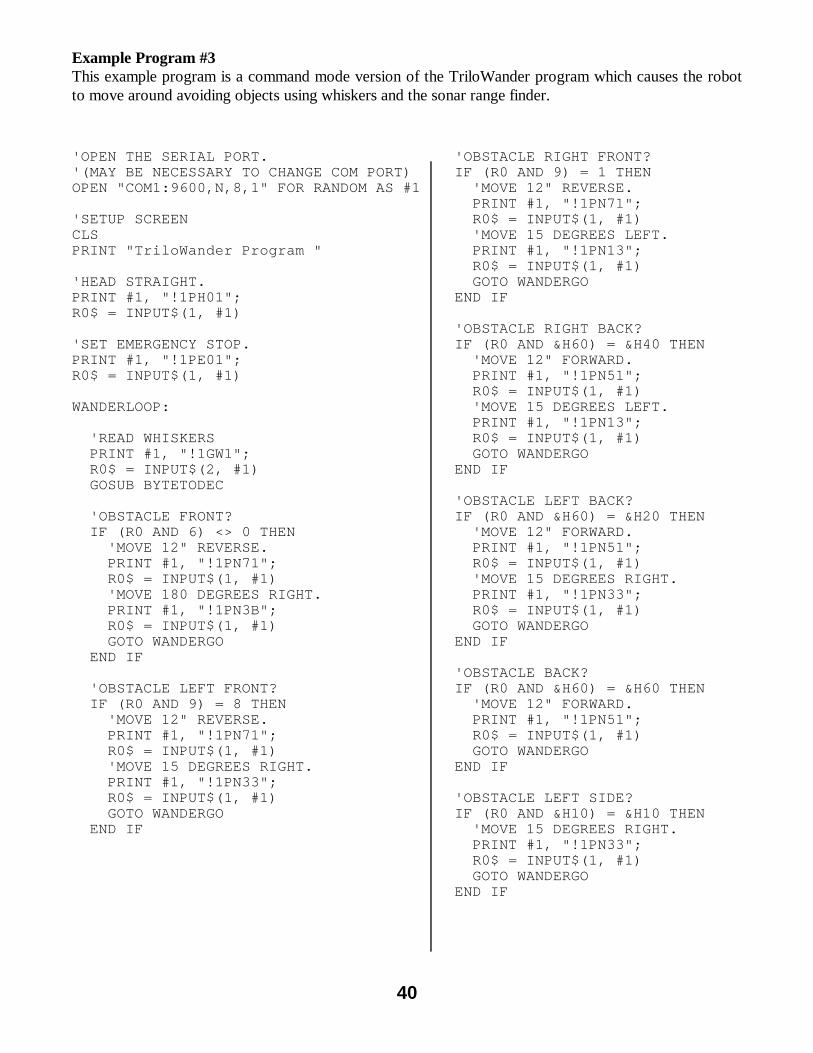
Example Program #3 This example program is a command mode version of the TriloWander program which causes the robot to move around avoiding objects using whiskers and the sonar range finder.
40
'OPEN THE SERIAL PORT. '(MAY BE NECESSARY TO CHANGE COM PORT) OPEN "COM1:9600,N,8,1" FOR RANDOM AS #1 'SETUP SCREEN CLS PRINT "TriloWander Program " 'HEAD STRAIGHT. PRINT #1, "!1PH01"; R0$ = INPUT$(1, #1) 'SET EMERGENCY STOP. PRINT #1, "!1PE01"; R0$ = INPUT$(1, #1) WANDERLOOP: 'READ WHISKERS PRINT #1, "!1GW1"; R0$ = INPUT$(2, #1) GOSUB BYTETODEC 'OBSTACLE FRONT? IF (R0 AND 6) <> 0 THEN 'MOVE 12" REVERSE. PRINT #1, "!1PN71"; R0$ = INPUT$(1, #1) 'MOVE 180 DEGREES RIGHT. PRINT #1, "!1PN3B"; R0$ = INPUT$(1, #1) GOTO WANDERGO END IF 'OBSTACLE LEFT FRONT? IF (R0 AND 9) = 8 THEN 'MOVE 12" REVERSE. PRINT #1, "!1PN71"; R0$ = INPUT$(1, #1) 'MOVE 15 DEGREES RIGHT. PRINT #1, "!1PN33"; R0$ = INPUT$(1, #1) GOTO WANDERGO END IF
'OBSTACLE RIGHT FRONT? IF (R0 AND 9) = 1 THEN 'MOVE 12" REVERSE. PRINT #1, "!1PN71"; R0$ = INPUT$(1, #1) 'MOVE 15 DEGREES LEFT. PRINT #1, "!1PN13"; R0$ = INPUT$(1, #1) GOTO WANDERGO END IF 'OBSTACLE RIGHT BACK? IF (R0 AND &H60) = &H40 THEN 'MOVE 12" FORWARD. PRINT #1, "!1PN51"; R0$ = INPUT$(1, #1) 'MOVE 15 DEGREES LEFT. PRINT #1, "!1PN13"; R0$ = INPUT$(1, #1) GOTO WANDERGO END IF 'OBSTACLE LEFT BACK? IF (R0 AND &H60) = &H20 THEN 'MOVE 12" FORWARD. PRINT #1, "!1PN51"; R0$ = INPUT$(1, #1) 'MOVE 15 DEGREES RIGHT. PRINT #1, "!1PN33"; R0$ = INPUT$(1, #1) GOTO WANDERGO END IF 'OBSTACLE BACK? IF (R0 AND &H60) = &H60 THEN 'MOVE 12" FORWARD. PRINT #1, "!1PN51"; R0$ = INPUT$(1, #1) GOTO WANDERGO END IF 'OBSTACLE LEFT SIDE? IF (R0 AND &H10) = &H10 THEN 'MOVE 15 DEGREES RIGHT. PRINT #1, "!1PN33"; R0$ = INPUT$(1, #1) GOTO WANDERGO END IF
'OBSTACLE RIGHT SIDE? IF (R0 AND &H80) = &H80 THEN 'MOVE 15 DEGREES LEFT. PRINT #1, "!1PN13"; R0$ = INPUT$(1, #1) GOTO WANDERGO END IF 'GET SONAR. PRINT #1, "!1GS1"; R0$ = INPUT$(2, #1) GOSUB BYTETODEC IF R0 < 7 THEN R0 = 255'FIX LOW VALUES. 'IF < 12" THEN RESPOND. IF R0 < 12 THEN 'MOVE 6" REVERSE. PRINT #1, "!1PN70"; R0$ = INPUT$(1, #1) 'MOVE 45 DEGREES RIGHT. PRINT #1, "!1PN36"; R0$ = INPUT$(1, #1) GOTO WANDERGO END IF WANDERGO: 'SET WHISKER AUTO STOP TO FRONT. PRINT #1, "!1PW0F"; R0$ = INPUT$(1, #1) 'MOVE FORWARD 50' WITHOUT WAIT. PRINT #1, "!1PN4C"; R0$ = INPUT$(1, #1) GOTO WANDERLOOP 'Add hex conversion 'subroutines here.
Example Program #3 Continued
41
The Trilobot Program
These instructions assume that the user posses basic computer skills such as copying files, making directories and running programs. Your computer or operating system may require different commands. See your computer manuals for exact details. About the Trilobot Program The Trilobot program is a DOS-based program written to run on IBM-style personal computers. It is not a full-featured control program, only a simple example used for demonstration purposes. It allows the operator to control most functions of the robot and to read sensors. The program is supplied in its executable form (.EXE) and the QBasic source code (.BAS) is also provided. The source code is provided so the user can make modifications and add improvements, and so new programs can be written without having to start from scratch. Installing the Software The Trilobot software is provided on a high density 3.5" (1.44mb) diskette. The software can be run from the distribution floppy, a backup floppy, or from the hard disk. To make a backup copy of the distribution diskette, check the manual for your operating system and look for the section covering the formatting and copying of diskettes. Installation is performed by simply coping the diskette contents to the hard disk. If using an Operating System such as Windows ™, use it to create a directory and copy the programs from the diskette to the hard disk. The following commands can be used from the DOS prompt to copy the software from the floppy disk to the hard disk. These commands assume that the floppy disk drive is A: and that the hard disk is C:. The first command makes a directory called "Trilobot" and the second command copies all of the files to that directory. md c:\trilobot copy a:*.* c:\trilobot Running the Trilobot Program You can run the Trilobot program from the DOS prompt or through QBasic which is provided with many versions of DOS. To run the Trilobot program from the DOS prompt, type the following commands. This assumes that the Trilobot program resides on the C: hard disk. The first command changes the active directory to the "trilobot" directory and the second command runs the Trilobot program. cd c:\trilobot trilobot To run the Trilobot program from QBasic, use the following commands. cd c:\trilobot qbasic trilobot.bas Using the Trilobot Program Usage of the program is very self-explanatory. A menu is supplied which lists various commands used to control the robot. Each command is selected by typing the character to the left of the command. A list of sensor conditions is also displayed. Make sure that the Trilobot is in Command Mode.
42
43
Commands Status
S - Sound effects G – Gripper Motion H – Head Motion R - Rotate M - Manual Entry L – Lights D - Drive U – Update Status C – Continuous Update Q - Quit
Trilobot Control Program V2.0
Entry
Enter Command: _
Using the Trilobot Program The Trilobot program allows the user to control each function of the robot using simple keystrokes. Sensors can be read and the drive and servo motors can be controlled. Activate each command in the menu using a single key press listed beside the command. The status window displays all of the sensor results as of the last request. Sensor results can be updated manually or continuously. Make sure that the Trilobot is in Command Mode.
The Trilobot Program
Battery: 11.6 volts Whiskers: Off Compass: North Sonar: 12" Light level: 146 Sound level : 15% PIR: Off Temperature: 76° Tilt: Flat
44
Assembly Language Programming
This section is designed to answer some common questions about assembly language programming on the Trilobot. It is not designed to teach assembly language programming which can be a very compli-cated matter and requires knowledge of many details about the CPU and associated hardware. The pro-grammer must have assembly language programming knowledge to create these programs. To program in assembly language, you’ll need an 8051 (actually an 80C32) assembler which creates Intel hex files. There are assemblers on the Internet that may serve this purpose. Arrick Robotics offers an as-sembler which can be seen on our web site at http://www.robotics.com/trilobot The term ‘8051’ is used to identify an entire series of microcontrollers initially designed by Intel. The CPU used on the Trilobot is actually an 80C32 which is part of that family. We highly suggest you ac-quire an 8051 data book or programming book and learn the details of the 8051 CPU. Other manufac-turers such as Philips, Atmel, and Harris Semiconductor also produce 8051-style microcontrollers. The 80C32 CPU on the Trilobot has the following specifications: � 11.059Mhz Processor speed � 64K external EPROM (code space) � 32K external battery backed RAM (data space) � 2K EEPROM for storage of parameters � 256 bytes of internal RAM � 3 timers (one used for baud rate) � I/O circuitry used to access the Trilobots hardware � Hardware UART (Serial port) and 2 software-driven serial ports Memory The 80C32 processor has a 64k section of program space which is read only, and a 64k section of data space which is read/write. The Trilobot’s system program resides in the top 32k of the 64k EPROM in program space. The bottom 32k of EPROM contains interrupt vectors and data for speech. This bottom section can be overwritten with a user program at the expense of speech. Calls can be made to the utility routines in the upper 32k of the EPROM. An EPROM programmer would be required for this. Special circuitry is used to place the 32k of RAM into the bottom 32k of program space normally occu-pied by EPROM. This allows the user to download a program into the RAM then swap it into program space for execution. Data in the lower 32k of EPROM will not be accessible. The RAM will simultane-ously appear in program space and data space so it can also be used to store variables in areas where the program does not exist. It is necessary to copy the interrupt vectors from EPROM to RAM before switching RAM into program space to allow interrupts to work. The RAM is backed up using a battery and will be retained when power is removed. Setting the startup parameter from the OPTIONS menu will allow these custom programs to be run automatically upon power up or reset. TRILODEF.ASM A file named ‘TRILODEF.ASM ’ is provided which defines functions and variables that are available to the assembly language programmer. All of these routines exist in the upper 32k of EPROM so that when your program is downloaded into RAM then switched into code space they are still accessible.
45
Memory Map
Code Space 64K total
0
FFFFh
8000h
Interrupt Vectors
Speech Data
80h
System Software
0
8000h
RAM (32K)
Hardware I/O Ports
FFFFh
Data Space 64K total
This memory map is when MEMODE=1 MEMODE A control bit named MEMODE is used to place RAM into code space so a program which has been downloaded into RAM can be executed. Upon reset, MEMODE is set to 1 which causes all 64k of EPROM to reside in code space, and 32k of RAM to reside at 0000-7fff in data space. When MEMODE is 0, the 32k of RAM also appears in the bottom half of code space in addition to it's data space location. Remember that interrupt vectors are the bottom of EPROM and must first be copied to RAM before switching. See the SYSCV routine in the TRILODEF.ASM file. When selecting ‘RUN FROM RAM’ from the ‘RUN USER PROGRAM’ menu, interrupt vectors will automatically be copied into RAM and the RAM will be moved into code space by changing MEMODE to 0, then the program will be jumped to at the supplied address. PROCEDURE The procedure for writing and executing assembly language programs is as follows: 1. Create an assembly language program and include the TRILODEF.ASM file to allow access to system functions 2. Assemble the program to create an Intel hex file. Other formats will not download. 3. Connect the Trilobot’s serial port to your computer’s serial port. 4. Set the communications parameters on your computer to 9600,N,8,1 which can be done with the DOS command mode com1:9600,n,8,1 5. Select ‘DOWNLOAD/UPLOAD’ from the Trilobot’s main menu, then press the down arrow key to select download. 6. Send the hex file to the Trilobot. This can be done using the DOS command copy c:\trilobot\example7.hex com1: (if the program name is example7.hex) 7. You will be asked if you would like to run from RAM. Select ‘Y’ and enter the starting address as 4 hex digits (usually 0100).
EPROM (64K)
46
The following batch file is an example of one that can compile an assembly language program and copy the file to the serial port. Assumes COM1 serial port connected to Trilobot. Assumes example7.asm program is in C:\TRILOBOT directory. Assumes Dunfield Micro-C/asm is in C:\MC directory. Set Tri-lobot to download mode first. cd \trilobot c:\mc\macro example7.asm > example7.as c:\mc\asm51 example7.as -I -F -S mode com1:9600,n,8,1 copy c:\trilobot\example7.hex com1: PROGRAM LOCATION A good place to put your assembly language program is at 100h which is well above the interrupt vec-tors. There are some locations high in RAM that are used for I/O buffers. See the TRILODEF.ASM file for details. Hardware I/O MAP All hardware functions can be controlled through the functions defined in the TRILODEF.ASM file. There is no need to directly access the hardware I/O ports and therefore no need to list them here. It is important to prevent your program from writing to 8000h-ffffh in the data area.
;Example7.asm program. include "trilodef.asm" ;Trilobot system definitions. org 0100h ;Start program above vectors. ;LCD signon. ex7: lcall trmclr ;Clear LCD. lcall trmpsi ;Message on LCD. db 0 ;Top line. str 'Trilobot' db 0 lcall trmpsi ;Message on LCD. db 40h ;Bottom line. str 'Example7.asm' db 0 ;Wait. mov a,#1 ;Wait 1 sec lcall utlwas ;Sound signon. mov a,#8h ;'Hello' code. lcall sndput ;If N key pressed then return to system ex70: lcall trmgk ;Get keypad status. jnc ex71 ljmp sysres ;If key pressed then return ;to system. ;Check dip switch. ex71: lcall utlgd ;Get dip switch into A. ;Dip switch #1. jnb acc.0,ex72 ;If switch #1 ON then lcall utlhlon ;Headlight on, ljmp ex73 ex72: lcall utlhloff ;else Headlight off. ;Dip switch #2. ex73: jnb acc.1,ex74 ;If switch #2 ON then lcall utllaon ;Laser on, ljmp ex75 ex74: lcall utllaoff ;else Laser off. ;Dip switch #3. ex75: jnb acc.2,ex76 ;If switch #2 ON then lcall utlrlon ;red LED on, ljmp ex77 ex76: lcall utlrloff ;else red LED off. ;Dip switch #4. ex77: jnb acc.3,ex78 ;If switch #2 ON then lcall utlglon ;green LED on, ljmp ex70 ex78: lcall utlgloff ;else green LED off. ljmp ex70 ;Loop. end
47
Hardware
48
Batteries
The battery tray can be removed to change batteries or to exchange the tray with another. Turn the power off first then remove the batter cable from the controller board. Loosening the two thumbscrews in front of the battery tray will allow the tray to be removed. Pay close attention to the battery polarity when inserting new batteries. The battery cable connector is keyed to prevent incorrect connection. A fuse located under the battery connector will blow if the batteries are installed backwards. If this happens, fix the battery polarity and replace the fuse with one of the same. Important Warnings � Always turn power off before replacing batteries. � Be very careful with batteries. Do not short their leads. Even D-cell batteries can cause great heat and sparks when shorted. Batteries can weld metal objects such as screwdrivers. Always follow the manufacturers instructions concerning battery usage. � Never attempt to recharge alkaline or other types of batteries that are not designed to be recharged! Battery Options The user has several options to provide power to the Trilobot. Some of these options require special cables and special mounting hardware. Please refer to the power connector pinout for detailed information when building custom cables. Reversed power connections will result in a blown fuse. Here are the most common power options: � 8 – D-cell batteries (Ni-Cad or alkaline) � Cable tether to external 12 volt power supply � 2 – 7.2 volt Ni-Cad RC car battery packs � 2 – 6 volt lead-acid gel-cell Current Consumption The Trilobot uses approximately .4 amps (400ma) of current when the drive and servo motors are not running. Use a 25% margin when calculating run time and battery capacity. Duracell (tm) alkaline batteries have a 15 amp/hour capacity which would provide about 24 hours of run time. Good Ni-Cad D-cell batteries offer 4 amp/hour capacity which would provide about 7 hours run time. When moving, both drive motors normally consume 1 amp total. This value can be used to calculate approximate run time with drive motor usage. Servo motors can draw as much as .5 amps each although they are normally energized only for a short time. Unless excessive head, gripper, or user servo motor usage is occurring, it's safe to ignore their power consumption. At power on or reset, the Trilobot will check and report a low battery. If the battery voltage is too low, automatic power off will occur.
The Trilobot is designed to run on 9-15 volts. This can be provided by 8 D-cell batteries using the supplied battery holder. Although Duracell (tm) alkaline batteries tend to cost more, they seem to work very well for the Trilobot and will supply additional run time. Ni-Cad batteries can be re-charged but have only about 1/4 the capacity as quality al-kaline batteries. Alkaline batteries are about 1 oz heavier than Ni-Cads.
49
Head
Mast
The Trilobot’s head contains many sensor and can be moved left/right (azimuth), and up/down (altitude). This alt/az configuration is common to camera mounts, telescope mounts, and satellite dishes. The head has the following devices: � PIR (Passive Infrared) motion detector � Ultrasonic range finder � Headlight � IR headlight � IR receiver � Microphone � Laser pointer Two servo motors are used to control the movement of the head. On the azimuth axis, a servo motor drives a 1:1 gear ratio which turns the head almost 180 degrees. On the altitude axis, a servo motor uses mechanical linkages to point the head up 90 degrees and down approximately 15 degrees. To insure that head-mounted devices do not collide with handle, never turn the head left/right when it’s pointed up or down.
The mast is a stationary circuit board at the very top of the Trilobot. It houses many sensors that need to be unobstructed such as the compass sensor and light level sensors. The mast does not move with the head but stays oriented with the body. The mast contains the following sensors. � Digital compass � Tilt sensors � Directional light sensors � IR communications transmitter � Red and Green LED indicators � Temperature sensor
Fuse The fuse is located above the battery connector on the controller board. Always replace the fuse with one of the same type and value. The fuse is designed to protect against these conditions: � Reversed batteries or power connector � Short circuits caused by debris or obstacles � Defective circuits � Connectors plugged in wrong � Oversized accessories � Defective user circuits
50
Drive Motors and Encoders
The Trilobot is driven with 2 DC gear motors with optical encoder feedback. These motors can be con-trolled independently to move straight, rotate on center, or turn in an arc. An H-Bridge IC is used to drive the motors using PWM (pulse width modulation). See the glossary for definitions of these terms. A coprocessor is dedicated to the function of drive motor control. Optical encoder feedback is used to monitor the speed and position of the wheels. The optical encoder consists of a rotating wheel with slots. An optical interrupter is used to sense the slots. Calculations are made to determine the speed and position of the drive wheels using the information from the encoders. Drive motors Specifications: Type: Permanent magnet DC motor with gearhead. Electrical: 12 volt, .5 amp no load, 1.6 amp full load. Torque: 112 Oz/in. Speed: 73 RPM full load. Shaft: .25" diameter. Driver: H-bridge with EMI filter. Encoder Specifications: Type: Single channel incremental. Sensor: Optical interrupter. Resolution: 22 counts per revolution. Approximately 4 counts per inch of travel using edge detection.
51
Gripper
The Trilobot’s gripper can be used to grasp and lift objects such as soda cans and tennis balls. Two RC servo motors are used to control the gripper mechanics – one for gripping, and one for lifting. A me-chanical switch is also provided on the gripper finger to indicate the presence of an object. Custom Fingers Gripper fingers are attached using 4 4-40 screws. Fingers can be removed and replaced with custom fin-gers designed for grabbing other types of objects. Gripper Switches A mechanical lever-style switch is provided on the gripper fingers to detect objects. This switch can be replaced with other types of switches including mechanical and optical types. Gripper Specifications: Typical object size: 1.75 – 2.5” diameter. Lift capacity: 8 oz. Lift height: 1.5” at end of fingers.
Whiskers
Mechanical whisker switches are mounted around the Trilobot's base and become active when the robot comes in contact with a wall or other obstruction. Unlike the ultrasonic sensor which is a collision avoid-ance device, whiskers are collision detection devices. Each of the 8 whiskers can be independently read. Programs can use the status of the whiskers to aid navigation and to activate special collision routines. These routines could search for a way around the obstacle and make provisions for future paths. Whiskers are conductive wires that will touch a metal bracket when bent. It's important that these wires are not touching the metal bracket when inactive. Wires that are too close to the metal bracket make ac-tivate due to vibration caused by moving. Bend the whisker wire so that it rests near the center of the bracket. It is possible to make substantial changes to the whisker system. Other types of switches including me-chanical and optical types can be used in place of the whiskers. Whisker Specifications: Type: Conductive whisker wires Length beyond base: Approximately 2.5 inches Arrangement: 2 in front, 1 left front, 1 right front, 1 left side, 1 right side, 1 right rear, 1 left rear.
52
Shoulder Buttons
Each side of the Trilobot's body has a momentary push button that can be read by the programmer. The button on the right side is green in color, the button on the left side is red. They are not connected to-gether and can be read separately. The buttons are located so they are easily accessed by operators while the robot is moving. No specific purpose is designated for these buttons. Possible uses include: emer-gency stop, selecting of actions, and parameter input. These buttons are electrically the same as the two joystick buttons. The red shoulder button is sometimes used as emergency stop by the system software and command mode programs.
Dip Switches
A digital compass is located on the Trilobot's mast. Very sensitive sensors detect the Earth's magnetic field in order to calculate a heading. The heading accuracy is 2 degrees. The location of the compass helps minimize interference by nearby objects that may disrupt the magnetic field. Uneven surfaces and nearby metal objects can affect the accuracy of the compass. Reading the compass takes approximately 1/4 of a second, so be careful how it's used when programming. The compass is used to aid navigation.
Compass
A 4-position DIP switch can be found on the top left edge of the Trilobot’s controller card. The switches can be used as general purpose inputs. Programs can be written to read the status of the DIP switches and act according to their positions.
The ultrasonic range finder is used to detect the distance to nearby objects and is one of the most impor-tant sensors on the Trilobot. This is done by emitting a series of high frequency sound signals through the transducer and measuring the time it takes for them to return. The ultrasonic transducer and receiver are mounted on the head which allows positioning before taking a reading. This prevents the robot from having to turn using the drive motors in order to scan an area. The distance to the object is determined by the following formula: Distance in inches = (Total travel time in seconds / Distance sound travels in 1 second) / 2 The calculation is begun by measuring the time from the beginning of the transmit pulse until the echo is received. This time is divided by the distance that sound travels in 1 second. The result is then divided by 2 since the signal must travel to the object then back to the transducer. Ultrasonic range finding is not perfect. There are a few occasions where the range finder will not operate as expected. When an obstacle is outside the minimum or maximum range, the range finder may return an incorrect result. Objects such as carpets and drapes sometimes absorb so much of the sound energy that the returned wave is too small to detect. Trying to sense walls at a sharp angle may also cause incor-rect results as the signals bounces around. Some high-frequency sounds such as keys rattling can mislead the receiver. Moving air from fans can also result in false returns. Take multiple readings to increase the reliability of the results when needed. Ultrasonic Range Finder Specifications: Minimum Distance: 6" Maximum Distance: 180” (12 feet) Accuracy: +/- 1" Frequency: 40 KHz
Temperature A digital temperature sensor is provided which senses the ambient air temperature near the mast. The re-turned value is in Fahrenheit. Programs can be written to read this sensor and perform certain actions based on its readings. Temperature Sensor Specifications: Sensor: LM34D Minimum Temperature: 32 º F Maximum Temperature: 120 º F Accuracy: +/-1 º F Resolution: 1 º F
Light Level Sensors
54
Four light level sensors are placed around the mast – front, back, left, and right. These sensors return a value 0-255 which indicates the light intensity. Various lighting conditions such as sunlight, normal room light, and a dark room can be recognized. Direction of light sources can be determined also. A program could be written to detect when someone turns on a light then perform a certain task. Before programming, use the test menu and record various light levels. The four sensors may respond differ-ently. Light Level Sensor Specifications: Sensor: CdS Photo conductive cell Range: 10 lux - 100 lux
Tilt Sensors
There are four tilt sensors located on the mast that can be used to detect the following conditions: tilted front, back, right, left, upside down. The sensors are constructed as metal tubes which are filled with a conductive liquid. When the liquid will cause a switch contact when tilted beyond a certain level. The tilt sensors can be used to determine if the robot is on an uneven surface or has fallen over. Tilt information can also be used to determine if the compass heading can be trusted. Tilt Sensor Specifications: Arrangement: 2 axis via 4 sensors Type: Conductive fluid switch Operating angle: 18-25 degrees
Water Sensor
A small PCB is mounted near a wheel and can be used to detect puddles of water. The depth of the wa-ter must be approximately 1/8”. The sensor may continue to detect water for some time after water has been removed.
Passive Infrared Motion Detector
55
The PIR sensor is located on the head and is used to detect moving living objects. A pyroelectric sensor is mounted under a fresnel lens along with a control circuit which passes a signal to the CPU. Use the sensor to detect movement of people and animals like the TriloGuard program does. Since the PIR sen-sor is designed to detect moving objects, false readings can occur when the head is moved. Moving hot air, direct sunlight, and reflections of sunlight can also cause false readings.
Headlight
LED’s
Laser Pointer
The headlight is mounted on the head and can be turned on and off under program control. Use it to light a pathway in the dark or for dramatic effect. Two IR (Infrared) LEDs are also attached to the headlight circuitry and emit enough IR energy to help digital cameras see in the dark. Replace the headlight with a style #222 light bulb which can be found a hardware and electronic stores.
A laser pointer is mounted to the head and can be turned on and off under program control. This laser is provided as a general-purpose effect. And since it is mounted on the head it can be positioned easily. Never look directly into a laser.
There are two LED’s (light emitting diode) located on the mast. A green one on the right side and a red one on the left side. These can be used as general purpose indicators and can be independently controlled through programming. Use the LED’s to indicate the status of a program, error conditions, or simply for dramatic effects.
Sound Input/Output
56
Both audio input and output circuits and transducers are provided on the Trilobot. Sound effects, PWM Speech, Speech Synthesizer Sound effects are simple tones, wooping sounds, etc. PWM speech is crude speech generated by reading prerecorded data from EPROM or RAM and is very limited. An optional speech synthesizer can be at-tached to the expansion port to create high-quality speech from text given by the CPU through the auxil-iary serial I/O port. The audio output circuitry consists of a lowpass filter and audio amplifier that drives a 3” speaker. The lowpass filter converts the digital signal from the CPU to an analog signal which allows the crude repro-duction of speech. Speech requires 8k of memory per second. Simple sound effects can also be gener-ated without consuming memory. An input signal is provided on the expansion port that is mixed into the audio amplifier and can be used to attach speech synthesizers and other audio devices. The audio input circuitry consists of a microphone which is mounted on the head and an analog to digital converter that feeds into the CPU. The CPU can read the information from the microphone and store in memory or act upon the sound level. There is not enough processing power on the CPU to perform complex functions such as speech recognition but it is possible to write programs that make use of sound information. Recording Sounds The user can record sounds by selecting the “OPTIONS” menu then selecting “RECORD/PLAY SOUND”. Recorded sound will be stored in RAM. You will be asked for a starting address and ending address – each as 4 hexadecimal characters. Valid addresses are 0100 to 6FFF. Do not use any other ad-dress area to prevent corruption of output ports and special storage locations. For an example, enter 1000 as a starting address, and 1FFF as an ending address. This will result in about 1/2 second of sound. Record your sound by speaking into the microphone located on the head. A beep will notify you when recording is finished. You will be given the option of playing back the sound. Playing Sounds You can play sound effects and recorded sound by selecting the “TEST” menu then selecting “SOUND OUTPUT”. Enter “91” as the sound code which will play sound from 1000 to 1FFF. You will hear the sound that you previously recorded. Changing Startup Sounds You can change the startup sound by changing the startup sound code in EEPROM at location 6. Select the “OPTIONS” menu, then select “EDIT MEMORY”. Then select EEPROM. When asked for an ad-dress enter 0006 (you must enter all 4 digits). The current contents will be displayed. Press “Y” to edit the value. Enter the new value as 91 which is prerecorded sound at location 1000 to 1FFF. Press the re-set button to allow the changes to take effect and you will notice the new startup sound. Additional information about sound codes can be found in the command mode programming section un-der the “PA” command. Also see the EEPROM Usage section concerning the location and meaning of various control codes.
57
Infrared Input/Output
Data transmission in the form of Infrared (IR) can be received and transmitted. This can be used to read signals from an IR remote control or to communication with other Trilobots. The IR receiver can be found at the top/center of the head circuit board. The silver box has a detector mounted on one side that faces up when the head is facing forward. This allows reception from most di-rections. Data is received as RC5 code which is an industry standard coding system used to control ap-pliances such as TV’s and VCR’s. Normally the IR remote control should be programmed as a Philips TV/VCR. The software converts these codes into ASCII text characters that can be used by the soft-ware. The two IR LED’s used for transmitting can be found on the mast. They are oriented so that the IR ra-diation can be received from most directions. ASCII characters are converted into RC5 codes then trans-mitted.
Powerful Output
The Powerful Output is designed to drive high power loads up to 1 amp. Possible loads include large lights, small vacuum cleaners, or DC motors. A separate connector is provided for the powerful output where +12 volts is also supplied. The powerful output signal is active low. A power MOSFET is used to drive the signal to ground. See the connector section for additional information.
Connectors
Battery Connector
58
12 volt Accessory Connector
Reset Connector
Usage: Supplies battery power to all systems. Type: 4 pin, MTA .156
Usage: 12 volt unregulated power for accessories. Connector: 2 pin, MTA .1 Maximum current: 500 ma.
Pinout: 1 – Positive 2 – NC 3 – Key 4 – Negative
Pinout: 1 – +12 volts 2 – Ground
Usage: To reset hardware from external switch or circuit. Connector: 2 pin, MTA .1 Signal: Active low. TTL level.
Pinout: 1 – Ground 2 – -Reset
Joystick Port Connector
Usage: Connection to PC-type joystick.Connector: 15 pin, D-Subminature
Pinout: 1 – +5 volts 2 – Button 1 (active low) 3 – X axis analog input
4 – Ground 6 – Y axis analog input 7 – Button 2 (active low) Other pins are not connected
59
Console Port Connector
Terminal Connector
Usage: Connection to RS-232 serial device such as a computer. Connector: 4 pin or 6 pin RJ11 modular (phone style).
Pinout: 1 – +12 volts 2 – Ground 3 – RS-232 data out (from robot) 4 – RS-232 data in (to robot) 5 – -Cable installed signal 6 – Ground
Usage: Connects to LCD and keypad. Connector: 20 pin .1 IDC header
Usage: Connects controller to body mounted devices. Connector: 40 pin .1 IDC Header
Power supplies There are two separate 5 volt power supplies – 5Va and 5Vb. The 5Va supplies sensitive devices such as the processor and memory, 5Vb supplies potentially noisy devices such as RC servo motors, headlight, etc.
Head Connector
61
Pinout: Mast Signals: 1 – Compass Clock 2 – Compass Data 3 – Compass Slave Select 4 – Compass Reset 5 – Tilt Front 6 – Tilt Right 7 – Tilt Back 8 – Tilt Left 9 – Light Level Front 10 – Light Level Right 11 – Light Level Back 12 – Light Level Left 13 – IR Transmit 14 – Temperature 15 – LED Green 16 – LED Red 17 – +5Va 18 – +5Va 19 – Ground 20 – Ground
Head Signals: 21 – +12V 22 – +12V 23 – +5Vb 24 – +5Vb 25 – Ground 26 – Ground 27 – Sonar Transmit 28 – Sonar Receive 29 – Audio Input 30 – Video 31 – Headlight 32 – Laser Pointer 33 – IR Receiver 34 – PIR sensor 35 – Head Azimuth Servo 36 – Head Altitude Servo 37 – Key 38 – Startle 39 – NC (No connect) 40 – NC (No connect)
Usage: Connects controller to head and mast. Connector: 40 pin .1 IDC Header
Power supplies There are two separate 5 volt power supplies – 5Va and 5Vb. The 5Va supplies sensitive devices such as the processor and memory, 5Vb supplies potentially noisy devices such as RC servo motors, headlight, etc.
Drive Motors Connector
62
Usage: Connects drive motors to controller . Connector: 6 pin .1 MTA
Pinout: 1 – Motor #2 - 2 – Motor #2 + 3 – Ground 4 – Key 5 – Motor #1 - 6 – Motor #1 +
Powerful Output Connector
Usage: To control high-current external devices. Connector: 2 pin, MTA .1 Signal: Active low. (Sink to ground). Maximum current: 1 amp.
Pinout: 1 – +12 volts 2 – -Output
Circuit Example
1
2
Lamp
RC Receiver Connector
Usage: Reads up to 8 channels of information from an RC (Remote Control) receiver. Connector: 8 x 3-pin .1 header pins Signals: Active high pulse width 1-2ms.
3
1 2 3 4 5 6 7 8
S igna l
+5V
G nd3 3 3 3 3 3 3
2 2 2 2 2 2 2 2
1 1 1 1 1 1 1 1
Expansion
15131197531 17 19 21 23 25 27 29 31 33 35 37 39
161412108642 18 20 22 24 26 28 30 32 34 36 38 40
Expansion Connector
63
Pinout: 1 – User Digital I/O #1 2 – User Digital I/O #2 3 – User Digital I/O #3 4 – User Digital I/O #4 5 – User Digital I/O #5 6 – User Digital I/O #6 7 – User Digital I/O #7 8 – User Digital I/O #8 9 – Key 10 – User Analog Input 11 – Expansion Cable In 12 – Ground 13 – Ground 14 – +5Vb (100ma max) 15 – +5Vb 16 – +12V (1 amp max) 17 – +12V 18 – User RC Servo #1 19 – User RC Servo #2 20 – User RC Servo #3
21 – User RC Servo #4 22 – Auxiliary Transmit TTL * 23 – Auxiliary Receive TTL 24 – Auxiliary Transmit RS-232 25 – Auxiliary Receive RS-232 26 – CPU P3.4 27 – CPU P3.5 28 – Coprocessor Transmit TTL 29 – Coprocessor Receive TTL 30 – CPU Interrupt 31 – Reset Coprocessors 32 – Ground 33 – Audio Amp Input * 34 – NC (No Connect) 35 – NC (No Connect) 36 – NC (No Connect) 37 – NC (No Connect) 38 – +5Vb 39 – Ground 40 – Video from Head * Used for speech synthesizer.
Power supplies There are two separate 5 volt power supplies – 5Va and 5Vb. The 5Va supplies sensitive devices such as the processor and memory, 5Vb supplies potentially noisy devices such as RC servo motors, headlight, etc.
Expansion Circuit Examples
64
The Trilobot's expansion connector has 8 user-defined unused input/output signals that can be used to control accessories and to read sensors. +5 and +12 voltages are made available to power accessories. Observe current specifications to prevent overload of the power supply components on the controller board.
Digital Inputs - The 8 digital I/O signals can be used to read TTL level signals such as switches or sensors. The input signal should not exceed +5 volts DC or go below 0 volts. Each signal has a 10K pull-up resistor to +5 volts.
Switch Input Example: This example shows how to interface a mechanical switch to one of the digital inputs.
Sensor Input Example: This example shows how to interface a sensor that has an open collector (OC) output to a digital input.
Digital Circuit Input Example: This example shows how to attach logic gates to the digital input signals.
Digital/Power Output - The digital signals can be used to control external circuitry. Large loads can be driven with an external power transistor such as a MOSFET. A Clamping diode should be included to protect the transistor when switching inductive loads such as relays.
Power Output Example Digital Output Example
D ig ita lInpu t
M echan ica lSw itch
D ig ita lInput
74H C Series G a te
U serC ircu it
D ig ita lInpu t
O pen C o llecto rSensor
D ig ita lO u tpu t
74H C Series G a te
U serC ircu it
12 Vo ltD evice
12V 12V
2 x 1N 4000
D ig ita lO u tpu t
N C hanne lLogic Leve lM O SF ET
65
Analog Inputs - There is one analog input that can be used to read such devices as potentiometers, joysticks or sensors. The input voltage must be from 0 to 5 volts. The result is a number from 0 to 255 with each number representing approximately .0196 volts (5 / 255). An analog multiplexer such as a 74HC4051 can be used to add additional analog channels. Channels can be selected with the digital I/O port..
Temperature Sensor Example
Light Sensor Example Use with CDS cells and other sensors that vary resistance.
Protection Circuit Example Use this circuit to protect against high voltages and minus voltages.
Potentiometer Example Use this example to hook up potentiometers or joysticks.
+5V
Ana logInpu tPo t
5V
2 x 1N 4000
Ana logInput
F romAna logSource 100
5V
Ana logInpu tLm 34
+5V
Ana logInpu t
C dS C e ll
Analog Multiplexer This circuit adds analog input channels using an analog switch IC. The channel is selected using 3 digital output bits.
D ig ita lO u tpu ts
+5V
Ana logInput
74H C 4051Ana log
M ultip lexe r
12345678
Ana logInput
C hanne ls
13
14
15
16
11
10
9
6
12
1
5
2
4
8
3
Coprocessor Network Expansion
66
The Trilobot’s controller board contains a master 80C32 processor and two 87C52 processors that are used as intelligent coprocessors. For detailed information about these CPU chips, see the Intel web site at http://www.intel.com. The two coprocessors receive commands from the master processor using two serial I/O lines – One for transmit and one for receive. All commands sent from the master go to all co-processors and each responses from the coprocessors go only to the master. This creates a master/slave coprocessor network. Each command sent by the master contains an ID that determines which coproces-sor will respond. Each coprocessor has a unique ID to eliminate conflict. The coprocessors on the Trilo-bot’s controller have IDs of 2 and 3. The coprocessor network signals are available on the Expansion connector. These signals include: Transmit Data, Receive Data, Reset, and Interrupt – all of which are 0-5v CMOS levels. Power supply signals are also available. It is possible to create a custom coprocessor and attach it to the network. Custom coprocessors can be used to perform very complex, real-time, tasks such as motion control, vision processing, etc. This pre-vents the master processor from becoming overburdened. Each coprocessor must have software that waits for a specific address character preceded by an “!”. An example command would be “!4GS” (ID=4, command=GS). That ID must not be used by any other co-processor. Coprocessors must not transmit data unless asked to, due to the master/slave arrangement. It is possible for coprocessors to cause an interrupt on the master. At that point, the master can check all coprocessors. The following circuit shows an example of a coprocessor:
+5V
+5V
87C 51Transm it Data
Receive Data
Reset
Interrupt
1410
40
20
11
9
15
28
29
31
30
12
ExpansionC onnecto r
This circuit example excludes many important details such as bypass capacitors, processor crystals, etc.
Additional Information
Suggested Reading
67
PC AI Magazine Knowledge Technology, Inc. 3310 West Bell Rd., Suite 119 Phoenix, AZ 85023 (602) 971-1869 Periodical covering PC-based AI topics. Robot Science & Technology Magazine Dedicated to Real Robots. 2351 Sunset Blvd. Suite 170 Rocklin, CA 95765 http://www.robotmag.com 1-888-510-7728 Robotics Digest Practical Applications of Systems, Control, Vision, Motion, and Navigation in Robotic Mechanisms. Willian E. Gates 1700 Washington Ave. Rocky Ford, CO 81067 719-254-4558 [email protected] AI Expert Magazine Miller Freeman Inc. 600 Harrison St. San Francisco, CA 94107 (415) 905-2200 The magazine of artificial intelligence in practice. AI Magazine AAAI 445 Burgess Dr. Menlo Park, CA 94025 (415) 328-3123 Periodical by the American Association for Artificial Intelligence.
Computer Applications Journal 4 Park St. #20 Vernon, CT 06066 (203) 875-2751 Monthly periodical covering computer control projects. Embedded Systems Programming Miller Freeman Inc. 600 Harrison St. San Francisco, CA 94107 (415) 905-2200 Monthly periodical covering embedded computer programming. Robot Builder's Bonanza By Gordon McComb Tab Books ISBN 0-8306-2800-2 Book popular among some robot hobbyist containing many circuits and ideas about robot building. Artificial Life Explorer's Kit By Ellen Thro Sams Publishing ISBN 0-672-30301-9 Book covering artificial life, cellular automata and other various other interesting topics. Disk included. Artificial Life Lab By Rudy Rucker Waite Group Press ISBN 1-878739-48-4 Book covering artificial life programming and related topics. Disk included.
Intel Hex File Format
68
Intel hex files are created by assemblers and compliers. The file contains addresses and data in a text for-mat which can be view using a text editor such as notepad. The Trilobot has the ability to download Intel hex files into RAM for execution. Each line of the file begins with a colon. Most lines will contain 16 or 32 bytes of data. Here is an exam-ple line: (spaces are shown for clarity only and are not included in the file.
: 03 0000 00 02002B D0
Data bytes 2-byte address for this line.
Number of Data Bytes in this line.
Checksum
Notes: All values are in hexadecimal. Each line ends with a carriage return and/or linefeed character. The checksum byte is computed as two’s compliment of the eight bit sum of all values in the line. The final line will look something like this:
Record Type 00=Data 01=End
: 00 0000 01 FF
Record Type 01 indicates End
Component Suppliers
80/20 Inc. 2570 Commercial Rd. Fort Wayne, IN 46809 (219) 478-8020 Aluminum components used to create frames, benches and fixtures. Ampro Computers 990 Almanor Ave. Sunnyvale, CA 94086 (408) 522-2100 Manufactures a wide variety of computers and controller boards including PC/104 based systems. Bayside Controls 20-02 Utopia Pkwy. Whitestone, NY 11357 (800) 343-3353 Precision gear reducers for stepper and servo motors. Catalogs and technical information is available. Boston Gear 14 Hayard St. Quincy, MA 02171 (800) 343-3352 A good selection of medium and large gears, pulleys, gear reducers and shaft components. DU-BRO Products, Inc. P.O. Box 815 Wauconda, IL 60084 (708) 526-2136 Manufactures minature servo linkages and hardware.
69
The following list of suppliers has been compiled to help in the expansion of the Trilobot mobile robot. These vendors offer such items as single board computer, sensors and actuators. Most of the companies listed have catalogs which contain detailed part and technical information and can be obtained at little or no cost.
Edmund Scientific 101 E. Gloucester Pike Barrington, NJ 08007 (609) 573-6250 Optical and other educational supplies and equipment. Helical Products 901 W. McCoy Lane Santa Maria, CA 93456 (805) 928-3851 Manufactures precision shaft couplers. McMaster-Carr Supply Company P.O. Box 740100 Atlanta, GA 30374 (404) 346-7000 Huge catalog containing mechanical parts, tools and materials. Mouser Electronics 2401 Hwy 287 N. Mansfield, TX 76063-4827 (800) 346-6873 Distributor carring a variety of electronic components. Nordex 50 Newtown Rd. Danbury, CT 06810-6216 (203) 792-9050 Source for small gears, bearings, shafts and various other precision components.
PIC Design P.O. Box 1004 Middlebury, CT 06762 (203) 758-8272 Stocks a wide variety of gears, pulleys, bearings and lead screw assemblies. SAVA Industries 70 Riverdale Rd. Riverdale, NJ 07457 (201) 835-0882 Manufactures cables and pulleys. Small Parts 6891 N.E. 3rd Ave. P.O. Box 381736 Miami, FL 33238-1736 (305) 751-0856 This company stocks a broad range of precision parts such as screws, tubing, and tools. Stock Drive Products 2101 Jericho Turnpike New Hyde Park, NY 11040 (516) 328-0200 Broad line of precision mechanical components available including gears, pulleys, bearings and hardware. Metric sizes. Several catalogs and technical books are available. SuperCircuits 13552 Research Blvd, #B Austin, TX 78750 (512) 335-9777 Small video products including cameras and transmitters
70
Tower Hobbies P.O. Box 9078 Champaign, IL 61826-9078 (800) 637-6050 Catalog lists a wide variety of model kit components such as servos and linkages. Winfred M. Berg 499 Ocean Ave. East Rockaway, NY 11518 (516) 599-5010 The Berg catalog contains gears, bearings and large assortment of unusual belts and pulley systems. Z-World Engineering 1724 Picasso Ave. Davis, CA 95616 (916)757-3737 Manufactures single board computer for control applications.
Internet Robot Resources
71
The Internet contains a wide variety of resource pertaining to robots. Virtually all Universities provide research documents and files on the Internet for those interested. Many contain information about robot programming, navigation and control issues. This information can be obtained using a Web browser such as Netscape or via FTP (File Transfer Protocol). Various newsgroups are available that allow readers to exchange ideas and ask questions. Arrick Robotics maintains an Internet Web Site at http://www.robotics.com. At this site you can browse pages describing various product offerings and view the latest demonstration code and example programs. You can also send e-mail to [email protected] to get technical and sales questions answered. The following information is a sample of robot-related information available on the Internet at the time this manual was printed. Web Sites http://www.robotics.com/robots.html - Robotics Information Central http://www.robotics.com/trilobot - Trilobot Information Page http://www.robotics.com/mechpart.html - Mechanical Parts Source List http://www.robotics.com/robomenu - The RoboMenu allows you to show off your robot http://www.robotics.com/highload.html - Driving high-power loads http://www.controlled.com - Journal of Computer Controlled Systems, PC/104 http://www.dprg.org - Dallas Personal Robotics Group http://www.frc.ri.cmu.edu/robotics-faq - The Robotics FAQ (Frequently Asked Questions) http://www.ncc.com/misc/rcfaq.html - The Robotics Competition FAQ http://www.cs.ruu.nl/wais/html/na-dir/microcontroller-faq/.html - Microcontroller FAQ http://www.realtime-info.be/encyc/techno/publi/faq/rtfaq.htm - Real Time Computing FAQ http://piglet.cs.umass.edu:4321/robotics.html - UMass Laboratory for Perceptual Robotics http://mpfwww.jpl.nasa.gov - NASA Mars Pathfinder http://www.yahoo.com/Science/Engineering/Mechanical_Engineering/Robotics/ - Robotics at Yahoo http://robotics.eecs.berkeley.edu/ - UC Berkeley Robotics and Intelligent Machines Lab http://cwis.usc.edu/dept/robotics/ - Univ of S. CA Robotics Research Lab http://robotics.stanford.edu/home.html - Stanford Robotics Lab http://www.ai.mit.edu - Artifical Intelligence at MIT http://sfbox.vt.edu:10021/A/afalck/www/research/Controls-2.html - Line Following by Arturo Falck http://www.hut.fi/Misc/Electronics/opto.html - Tomi Engdahl's Optoelectronics / IR Page http://turbine.kuee.kyoto-u.ac.jp/staff/onat/servobasics.html - RC Servo Motor Basics by Ahmet ONAT http://www.engin.umich.edu/research/mrl/00MoRob_19.html - Robotics Aids for the Disabled http://ranier.oact.hq.nasa.gov/telerobotics_page/telerobotics.shtm - Telerobotics at NASA http://nimon.ncc.com/cdroms/ai/ - The AI CDROM from NCC For more links see: http://www.robotics.com/robots.html
comp.ai Artificial intelligence discussions. comp.ai.alife Research about artificial life. comp.ai.fuzzy Fuzzy set theory, aka fuzzy logic. comp.ai.genetic Genetic algorithms in computing. comp.ai.jair.announce Announcements of the Journal of AI Research. comp.ai.jair.papers Papers published by the Journal of AI Research. comp.ai.nat-lang Natural language processing by computers. comp.ai.neural-nets All aspects of neural networks. comp.ai.nlang-know-rep Natural Language and Knowledge Representation. comp.ai.philosophy Philosophical aspects of Artificial Intelligence. comp.ai.shells Expert systems and other artificial intelligence shells. comp.ai.vision Vision processing. comp.cog-eng Cognitive engineering. comp.edu.languages.natural Computer assisted languages instruction issues. comp.graphics.visualization Info on scientific visualization. comp.home.automation Home automation devices, setup, sources, etc. comp.lang.prolog Discussion about PROLOG. comp.lang.smalltalk Discussion about Smalltalk 80. comp.realtime Issues related to real-time computing. comp.robotics.misc All aspects of robots and their applications. comp.speech Speech processing comp.std.wireless Examining standards for wireless network technology. comp.sys.transputer The Transputer computer and OCCAM language. misc.books.technical Discussion of books about technical topics. misc.creativity Promoting the use of creativity in all human endeavors. rec.games.mecha Giant robot games. rec.models.rc Radio-controlled models for hobbyists. rec.radio.amateur.digital.misc Packet radio and other digital radio modes. rec.toys.lego Discussion of Lego, Duplo (and compatible) toys. rec.video Video and video components. sci.engr.control The engineering of control systems. sci.engr.mech The field of mechanical engineering. sci.fractals Objects of non-integral dimension and other chaos. sci.image.processing Scientific image processing and analysis. sci.lang Natural languages, communication, etc. sci.nanotech Self-reproducing molecular-scale machines. sci.virtual-worlds Virtual Reality - technology and culture. sci.virtual-worlds.apps Current and future uses of virtual-worlds technology.
72
Internet News Groups The following newsgroups are a goldmine of information. Most newsgroups have a FAQ (frequently asked questions) file associated with them that will answer many questions about the particular subject. Questions not answered in the FAQ can be posted to the newsgroup for a direct response from other readers. Newsgroup Name Description
Troubleshooting
73
The following list describes the most common problems and their remedies. Problem: Turning the power switch ON does not result in any activity. Remedy: The Trilobot is not getting power. Insure that the batteries are charged. Insure that the batteries are touching the contacts on the battery holder. Check the fuse. Insure that the power connector is plugged into the controller card. Remove the expansion connector to eliminate the possibility of defective expansion circuitry. Set EEPROM defaults by holding the ‘Y’ key down and pressing reset (see “Set Options” section). Problem: Fuse keeps blowing. Remedy: Check for any connector that may be attached to the controller wrong. Check for shorts caused by screws or brackets used by accessories. Check the cable harnesses for breaks or kinks. Remove any accessories which may be requiring excessive current. Contact Arrick Robotics if the problem persists. Problem: Whiskers activate without being touched Remedy: Make sure all whisker wires are resting in the center of the bracket’s hole. Make sure that the screw that holds the wire is tight. Problem: Display does not work. Remedy: Adjust viewing control on Terminal. (See “Terminal Usage” section). Insure that the cable is attached. Problem: One of the sensors does not work. Remedy: Check the cables for proper orientation, breaks or kinks. Problem: The compass sensor gives incorrect results. Remedy: Interference may be caused by nearby objects. Relocate the object or the compass sensor. Problem: The ultrasonic sensor gives incorrect results. Remedy: Read the section concerning the sonar and check for conditions that could cause false readings. Problem: The Trilobot quits working when the drive motors or accessory is activated. Remedy: A low battery could cause this. Problem: Communication can not be established with the Trilobot. Remedy: Insure you are using the correct communications port on your computer and have the parameters set correctly. Check for a bad or miswired cable. Remove questionable controllers. Check the controller ID (see “Set Options” section) and the console port baud rate.
74
Troubleshooting continued Problem: The light level sensor gives unusual readings. Remedy: Insure that the light sensor has access to the light and is not obstructed by an accessory. Problem: Robot does not drive in a straight line when requested to. Remedy: Try using a slower speed such as 2 or 3. Insure that the surface does not have bumps. Problem: Unable to download an Intel hex file. Remedy: Insure that the communications parameters are the same on both sides – usually 9600 baud, 8 data bits, 1 stop bit, no parity. In DOS this can be set using the MODE command. eg: mode com1:9600,n,8,1 After a failed download attempt, reset the Trilobot to clear the input buffer. Insure that the file is an Intel hex format. Verify that the file has a beginning address between 0000 and 7FFF. Problem: Some other problem Remedy: If you've read the manual and the problem still can't be resolved, don't waste another second, call us and get the answer. Or e-mail us at [email protected]
ARRICK ROBOTICS warrantees this product to be in good working order for a period of one (1) year from the date of purchase. Should this product fail to be in good working order at any time during this period, ARRICK ROBOTICS will, at its option, repair or replace the product at no additional charge except as set forth below. This limited warranty does not include service to repair damage to the product resulting from accident, disaster, misuse, abuse, or modification of the product. To obtain warranty service, send the product along with proof of purchase in its original packaging to: ARRICK ROBOTICS Attn: Repair Dept. 2107 W. Euless Blvd. Euless, TX 76040 You agree to prepay shipping charges and to insure the product or assume the risk of loss or damage in transit. All express or implied warranties for this product including the warranties of merchantability and fitness for a particular purpose are limited in duration to a period of one (1) year from the date of purchase, and no warranties, whether expressed or implied, will apply after this period. If this product is not in good working order as warranted above, your sole remedy shall be repair or replacement as provided above. In no event will ARRICK ROBOTICS be liable to you for damages, including any lost profits, lost savings or other incidental or consequential damages arising out of the use of or inability to use this product. Some states do not allow limitations on how long an implied warranty lasts, so the above limitations may not apply to you. Some states do not allow the exclusion or limitation of incidental or consequential damages for consumer products, so the above limitations may not apply to you. This warranty gives you specific legal rights and you may also have other rights which may vary from state to state.