Marine Display 15”/19”/24”/26” Flat PCAP Touchscreen (R2AH) r ECDIS Series Model No.: R15L600-MRA3FP R19L300-MRA1FP W24L100-MRA1FP W26L100-MRA1FP User Manual Version 1.0 Document Part Number: 91521110100X
In addition, free technical support is available from our engineers every business day. We are
always ready to give advice on application requirements or specific information on the
installation and operation of any of our products.
iv
Advisory Conventions Four types of advisories are used throughout the user manual to provide helpful information or to
alert you to the potential for hardware damage or personal injury. These are Notes, Important,
Cautions, and Warnings. The following is an example of each type of advisory.
NOTE: A note is used to emphasize helpful information
IMPORTANT: An important note indicates information that is important for you to know.
CAUTION/ ATTENTION A Caution alert indicates potential damage to hardware and explains how to avoid the potential problem. Une alerte d’attention indique un dommage possible à l’équipement et explique comment éviter le problème potentiel.
WARNING! / AVERTISSEMENT! An Electrical Shock Warning indicates the potential harm from electrical hazards and how to avoid the potential problem. Un Avertissement de Choc Électrique indique le potentiel de chocs sur des emplacements électriques et comment éviter ces problèmes.
ALTERNATING CURRENT / MISE À LE TERRE! The Protective Conductor Terminal (Earth Ground) symbol indicates the potential risk of serious electrical shock due to improper grounding. Le symbole de Mise à Terre indique le risquépotential de choc électrique grave à la terre incorrecte.
v
Safety Information
WARNING! / AVERTISSEMENT!
Always completely disconnect the power cord from your chassis whenever you work with the hardware. Do not make connections while the power is on. Sensitive electronic components can be damaged by sudden power surges. Onlyexperiencedelectronics personnel should open the PC chassis. Toujours débrancher le cordon d’alimentation du chassis lorsque vous travaillez sur celui-ci. Ne pas brancher de connections lorsque l’alimentation est présente. Des composantes électroniques sensibles peuvent être endommagées par des sauts d’alimentation. Seulement du personnel expérimentédevraitouvrirces chassis.
CAUTION/ATTENTION
Always ground yourself to remove any static charge before touching the CPU card. Modern electronic devices are very sensitive to static electric charges. As a safety precaution, use a grounding wrist strap at all times. Place all electronic components in a static-dissipative surface or static-shielded bag when they are not in the chassis. Toujours verifier votre mise à la terre afin d’éliminer toute charge statique avant de toucher la carte CPU. Les équipements électroniques moderns sont très sensibles aux décharges d’électricité statique. Toujours utiliser un bracelet de mise à la terre comme précaution. Placer toutes les composantes électroniques sur une surface conçue pour dissiper les charge, ou dans un sac anti-statique lorsqu’elles ne sont pas dans le chassis.
vi
Safety Precautions For your safety, carefully read all the safety instructions before using the device and
follow all warnings and cautions marked on the product. Keep this user manual for future
reference.
Always disconnect this equipment from any AC outlet before cleaning. Do not use
liquid or spray detergents for cleaning. Use a damp cloth.
For pluggable equipment, the power outlet must be installed near the equipment
and must be easily accessible.
Keep this equipment away from humidity.
Put this equipment on a reliable surface during installation. Dropping it or letting it
fall could cause damage.
The openings on the enclosure are for air convection and to protect the equipment
from overheating.
CAUTION/ATTENTION
Do not cover the openings!
Ne pas couvrir les ouvertures!
Before connecting the equipment to the power outlet make sure the voltage of the
power source is correct.
This product is equipped with a 3-wire grounding type plug, a plug having a third
(grounding) pin. This plug will only fit into a grounding-type power outlet. This is a
safety feature. If you are unable to insert the plug into the outlet, contact your
electrician to replace your obsolete outlet. (For AC version only).
Position the power cord so that people cannot step on it. Do not place anything
over the power cord.
If the equipment is not used for a long time, disconnect it from the power source to
avoid damage by transient over-voltage.
Never pour any liquid into an opening. This could cause fire or electrical shock.
Never open the equipment. For safety reasons, only qualified service personnel
should open the equipment.
All cautions and warnings on the equipment should be noted.
*Let service personnel to check the equipment in case any of the following problems
appear:
o The power cord or plug is damaged.
o Liquid has penetrated into the equipment.
o The equipment does not work well or you cannot get it to work according
to the user manual.
o The equipment has been dropped and damaged.
o The equipment has obvious signs of breakage.
vii
Do not leave this equipment in an uncontrolled environment where the storage
temperature is below -20°C (-4°F) or above 60°C (140°F). It may damage the
equipment.
CAUTION/ATTENTION
Use the recommended mounting apparatus to avoid risk of injury. Utiliser l’appareil de fixation recommandé pour éliminer le risque de blessure.
WARNING ! /AVERTISSEMENT! Only use the connection cords that come with the product. When in doubt, please contact the manufacturer. Utiliser seulement les cordons d’alimentation fournis avec le produit. Si vousdoutez de leur provenance, contactez le manufacturier.
WARNING!/AVERTISSEMENT! Always ground yourself against electrostatic damage to the device. Toujours vérifier votre mise à la terre afin que l’équipement ne se décharge pas sur vous.
Cover workstations with approved anti-static material. Use a wrist strap
connected to a work surface and properly grounded tools and equipment.
Use anti-static mats, heel straps, or air ionizer for added protection.
Handle electrostatic-sensitive components, PCB’s and assemblies by the case or
the edge of the board.
Avoid contact with pins, leads, or circuitry.
Turn off power and input signals before inserting and removing connectors or test
equipment.
Keep the work area free of non-conductive materials, such as ordinary plastic
assembly aids and Styrofoam.
Use filed service tools, such as cutters, screwdrivers, and vacuum cleaners that
are conductive.
Always put drivers and PCB’s component side on anti-static foam.
Important Information
viii
Countries/ Area Symbol This equipment complies with essential requirements of:
Restrictions of the use of certain hazardous substances (RoHS) Directive (2011/65/EU)
Internationally
Marine
IEC 60945 4th Edition
Federal Communications Commission Radio Frequency Interface Statement
This device complies with part 15 FCC rules.
Operation is subject to the following two conditions:
This device may not cause harmful interference.
This device must accept any interference received including interference
that may cause undesired operation.
This equipment has been tested and found to comply with the limits for a class "B" digital
device, pursuant to part 15 of the FCC rules. These limits are designed to provide reasonable
protection against harmful interference when the equipment is operated in a commercial
environment. This equipment generates, uses, and can radiate radio frequency energy and, if
not installed and used in accordance with the instruction manual, may cause harmful
interference to radio communications. Operation of this equipment in a residential area is likely
to cause harmful interference in which case the user will be required to correct the interference
at him own expense.
ix
European Union
This equipment is in conformity with the requirement of the following EU legislations and harmonized standards.Product also complies with the Council directions
EN55024: 2010 EN 55022: 2010 Class B o IEC61000-4-2: 2009 o IEC61000-4-3: 2006+A1: 2007+A2: 2010 o IEC61000-4-4: 2012 o IEC61000-4-5: 2014 o IEC61000-4-6: 2013 o IEC61000-4-8: 2010 o IEC61000-4-11: 2004
EN55022: 2010/AC:2011
EN61000-3-2:2014
EN61000-3-3:2013
Low Voltage Directive (2014/35/EU)
EN 60950-1:2006/A11:2009/A1:2010/A12:2011/ A2:2013
x
About This User Manual
This User Manual provides information about using the Winmate® ECDIS Marine Display.
The documentation set for the Winmate® ECDIS Marine Display provides information for specific
user needs, and includes:
ECDIS Marine Display Quick Start Guide- describes how to get the display up and running
ECDIS Marine Display User Manual – contains detailed description on how to use the
display, its components and features
NOTE:
Some pictures in this guide are samples and can differ from actual product.
Contents Preface ........................................................................................................................................ ii
About This User Manual ............................................................................................................... x
Introduction This chapter gives you product overview, describes features and hardware specification. You will find all accessories that come with your device in the packing list. Mechanical dimensions and drawings included in this chapter.
User Manual Chapter 1 Introduction
ECDIS Marine Display
1
1 Introduction
Congratulations on purchasing Winmate® ECDIS Marine Series Display. The design meets
the requirements of industrial marine standards, including IEC60945 4th Edition, DNV2.4,
IACS E10.
Modern marine sector requires durable devices that can withstand long periods
submersed in water. Winmate® ECDIS Marine Series Display is suitable for navigation,
ship automation, and surveillance, rugged industrial and light military applications.
Flat easy-to-clean surface delivers aesthetically pleasing look. Due to dimmable backlight
the Display suitable for high and low ambient light conditions. You can mount the
Display on the bridge of a ship. The Display features user-friendly and resistant to
scratches PCAP touch-screen. All models sealed with front IP 66 dust and water proof.
1.1 Product Features
Winmate® ECDIS Series Marine Display offers the following features:
Hyper Dimming
Anti-corrosion IP66 Proof
Projective capacitive multi-touch screen
Edge-to-edge narrow bezel design
Color calibrated for ECDIS compliance
Capacitive touch keys for quick function access and display control
(Support ECDIS DAY, DUSK, and NIGHT mode switching)
Support capacitive touch key lock / touchscreen lock function
Compliant with marine standards (DNV2.4, IEC 60945 4th, IACS-E10)
Approved Marine Display
Winmate’s Marine product line designed to follow IEC-60945 Maritime Navigation and Radio-
communication Equipment and Systems requirements. Marine Display series line varies in
screen size from 19 inches to 26 inches. By testing for usability in a ship’s wheelhouse during
different ambient light conditions we developed products that meet demands in maritime
applications especially for navigation, ship automation and maritime surveillance.
User Manual Chapter 1 Introduction
ECDIS Marine Display
2
1.2Packing List
Carefully remove the box and unpack yourdevice. Please checkif all the items listed
below are inside your package.If any of these items are missing or damaged contact us
immediately.
Standard factory shipment list:
Display User Manual Quick Start Guide
(Hardcopy) **M4 x 12 black
screw bolts
AC Adapter (Input 100-240V AC Output: 12V/ 80W)
Power Cord 3pin Terminal Block 1 x HDMI Cable
(HDMI 19pin Male to 19pin Male)
1 x VGA Cable (D-SUB 15pin Male to
15pin Male)
1 x RS232 Cable (D-SUB 9pin Male to
9pin Female)
1 x DVI Cable (DVI-D 24pin Male
to 24pin Male)
*AC adapter, 3-pin terminal block, and power cord shipped with Display for testing purposes only. **Notice: Screw bolts provided by Winmate only to be used to screw the display onto a console from the rear side. If you prefer your own bolts, please make sure to use M4 and 30mm in length.
User Manual Chapter 1 Introduction
ECDIS Marine Display
3
1.3Appearance and Layout
This section contains appearance of the Display and I/O layout.
1.3.1Appearance and Layout 15”
No Description No Description
① RS232 (Remote control) ④ DVI-D
② USB (for Touch) ⑤ VGA
③ HDMI 1.4 ⑥ DC Input
User Manual Chapter 1 Introduction
ECDIS Marine Display
4
1.3.2 Appearance and Layout 19”
No Description No Description
① RS232 (Remote control) ④ DVI-D
② USB (for Touch) ⑤ VGA
③ HDMI 1.4 ⑥ DC Input
User Manual Chapter 1 Introduction
ECDIS Marine Display
5
1.3.3 Appearance and Layout 24” and 26”
No Description No Description
① USB (for Touch) ④ DVI-D
② RS232 (Remote control) ⑤ VGA
③ HDMI 1.4 ⑥ DC Input
User Manual Chapter 1 Introduction
ECDIS Marine Display
6
1.4 OSD Control Keys
Capacitive touch keys and ECDIS mode indicators located on the front of your Display.
Capacitive Touch Keys
Touch Key Function Description
Power Power on/off control
Brightness To increase brightness of panel
Brightness To decrease brightness of panel
OSD/ Enter Opens OSD Menu or performs Enter button function
ECDIS Key/ ESC Switching ECDIS standard range mode (Day / Dust / Night mode) or performs ESC button function
User Manual Chapter 1 Introduction
ECDIS Marine Display
7
1.5 ECDIS Mode Indicators
ECDIS mode indicators notify users which mode is activated according to ECDIS standard.
ECDIS Mode Indicators
Icon Function Description
Day Mode Lights up when ECDIS brightness adjusted to day mode
Dusk Mode Lights up when ECDIS brightness adjusted to dusk mode
Night Mode Lights up when ECDIS brightness adjusted to night mode
User Manual Chapter 1 Introduction
ECDIS Marine Display
8
1.6Dimensions
This section contains mechanical dimensions of ECDIS Marine Display.
1.6.1 Dimensions 15”
User Manual Chapter 1 Introduction
ECDIS Marine Display
9
1.6.2 Dimensions 19”
User Manual Chapter 1 Introduction
ECDIS Marine Display
10
1.6.3 Dimensions 24”
User Manual Chapter 1 Introduction
ECDIS Marine Display
11
1.6.4 Dimensions 26”
ECDIS Marine Display
12
Mounting Solutions This chapter provides step-by-step mounting
guide for all available mounting options.
User Manual Chapter 2 Mounting Solutions
ECDIS Marine Display
13
2 Mounting Solutions
This chapter provides mounting guide for all available mounting options. Pay attention to cautions and warning to avoid any damages.
2.1 Cable Mounting Considerations
For a nice look and safe installation, make sure cables are neatly hidden behind the
device.
CAUTION/ ATTENTION Observe all local installation requirements for connection cable type and protection level. Suivre tous les règlements locaux d’installations, de câblage et niveaux de protection.
CAUTION/ ATTENTION Turn off the device and disconnect other peripherals before installation. Éteindre l’appareil et débrancher tous les périphériques avant l’installation.
2.2 Safety Precautions
Observe the following common safety precautions before installing any electronic device:
Use separate, non-intersecting paths to route power and networkingwires. If
power wiring and device wiring paths must be crossed make sure the wiresare
perpendicular at the intersection point.
Keep the wires separated according to the interface. Wires that share similar
electrical characteristics must be bundled together.
Do not bundle input wiring with output wiring. Keep them separate.
When necessary, it is strongly advised that you label wiring to all devices in
thesystem.
ALTERNATING CURRENT / MISE À LE TERRE! To prevent electrical shock, the Safety Ground location on the rear must be bonded to the local earth ground through a minimum 12 AWG wire as short as possible. Pour éviter les chocs électriques, l’emplacement de la prise terre àl’arrière doit être lié à terre locale, à travers un 12 AWG minimum et aussi court que possible.
User Manual Chapter 2 Mounting Solutions
ECDIS Marine Display
14
ATTENTION
User Manual Chapter 2 Mounting Solutions
ECDIS Marine Display
15
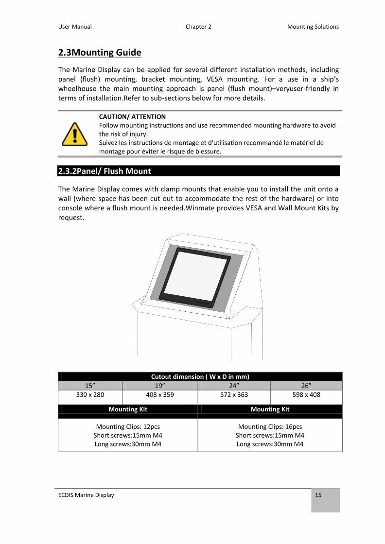
2.3Mounting Guide
The Marine Display can be applied for several different installation methods, including panel (flush) mounting, bracket mounting, VESA mounting. For a use in a ship’s wheelhouse the main mounting approach is panel (flush mount)–veryuser-friendly in terms of installation.Refer to sub-sections below for more details.
CAUTION/ ATTENTION Follow mounting instructions and use recommended mounting hardware to avoid the risk of injury. Suivez les instructions de montage et d'utilisation recommandé le matériel de montage pour éviter le risque de blessure.
2.3.2Panel/ Flush Mount
The Marine Display comes with clamp mounts that enable you to install the unit onto a wall (where space has been cut out to accommodate the rest of the hardware) or into console where a flush mount is needed.Winmate provides VESA and Wall Mount Kits by request.
Cutout dimension ( W x D in mm)
15” 19” 24” 26”
330 x 280 408 x 359 572 x 363 598 x 408
Mounting Kit Mounting Kit
Mounting Clips: 12pcs Short screws:15mm M4 Long screws:30mm M4
Mounting Clips: 16pcs Short screws:15mm M4 Long screws:30mm M4
User Manual Chapter 2 Mounting Solutions
ECDIS Marine Display
16
2.3.4VESA Mount
ECDIS Marine Display comes with VESA Mount holes for mounting.
VESA Plate Dimensions
15” 19” 24” 26”
100 x 100 100 x 100 150 x 150 100 x 200
Screw hole diameter
M4 D=3mm M6 D=5mm M6 D=5mm M6 D=5mm
User Manual Chapter 2 Mounting Solutions
ECDIS Marine Display
17
Mounting Steps:
1. Screw VESA bracket to the fixture (ex. wall) withfour screws (refer to the table
above for screw hole diameter).
2. Place the device on VESA bracket.
3. Connect all cables and peripheral devices. 4. When the installation is complete, plug the power cord into a grounded AC outlet.
Turn on the power.
NOTE:
Notice that both hooks on bracket should lock the notches on the
back cover of the device.
ECDIS Marine Display
18
Getting Started This chapter tells you important information on power supply, adapter and precautions tips. Pay attention to power considerations.
User Manual Chapter 3 Getting Started
ECDIS Marine Display
19
3Getting Started
This chapter provides information on how to connect the Display to the source of power,
connector pinouts and the guideline to turn on/off the Display.
3.1 Powering On
3.1.1 AC Adapter Components
Safety Precautions:
Do not use the adapter in a high moisture environment
Never touch the adapter with wet hands or foot
Allow adequate ventilation around adapter while using
Do not cover the adapter with paper or other objects that will reduce cooling
Do not use the adapter while it is inside a carrying case
Do not use the adapter if the cord is damaged
There are NO serviceable parts inside
Replace the unit if it is damaged or exposed to excess moisture
While using the AC Adapter always:
Plug-in the power cord to easy accessible AC outlet
Plug-in the AC adapter to a grounded outlet
AC Adapter (Input 100~240V AC Output 12V/80W)
Power Cord 3-Pin Terminal Block to
DC Jack
Note:
AC adapter, power cord and 3-pin terminal block to DC Jack provided by Winmate for
testing purposes only.
User Manual Chapter 3 Getting Started
ECDIS Marine Display
20
3.1.2 Connecting the Power
3.1.2.1 Connecting to AC Power Source (For testing)
1. Plug one end of the terminal block cable firmly to the DC IN Jack.
2. Plug the other end of the terminal block plug to the AC adapter.
3. Connect the AC adapter to the power cord.
4. Plug the power cord to a working AC outlet.The device will boot automatically.
3.1.2.2 Connecting to DC Power Source
ALTERNATING CURRENT / MISE À LE TERRE! This product must be grounded. Use only a grounded AC outlet. Install the additional PEground wire if the local installation regulations require it. *If you do not use a grounded outlet while using the device, you may notice an electrical tingling sensation when the palms of your hands touch the device. Ce produit doit être mis à la terre. Utiliser seulement un cordon d’alimentation avec mise à la terre. Si les règlements locaux le requiert, installer des câbles de mise à la terre supplémentaires. *Si vous n’utiliser pas une prise d’alimentation avec mise à la terre, vous pourriez remarquer une sensation de picotement électrique quand la paume de vos mains touche à l’appareil.
Note:
Power cords vary in appearance by region and country.
User Manual Chapter 3 Getting Started
ECDIS Marine Display
21
1. Insert the exposed wires of the DC Power Cable to the appropriate connectors on
the terminal block plug.
2. Plug the terminal block plug firmly to the DC IN Jack.
3. Connect the other end of the DC power cable (wires with lug terminals that are
labeled + and – to the terminals of the 9~36V DC Power Source. Ensure that the
power connections maintain the proper polarity.
CAUTION/ATTENTION Make sure that the polarization of the power lines is correct and complete including chassis ground. Wrong polarization will result in serious damage to the equipment.
User Manual Chapter 3 Getting Started
ECDIS Marine Display
22
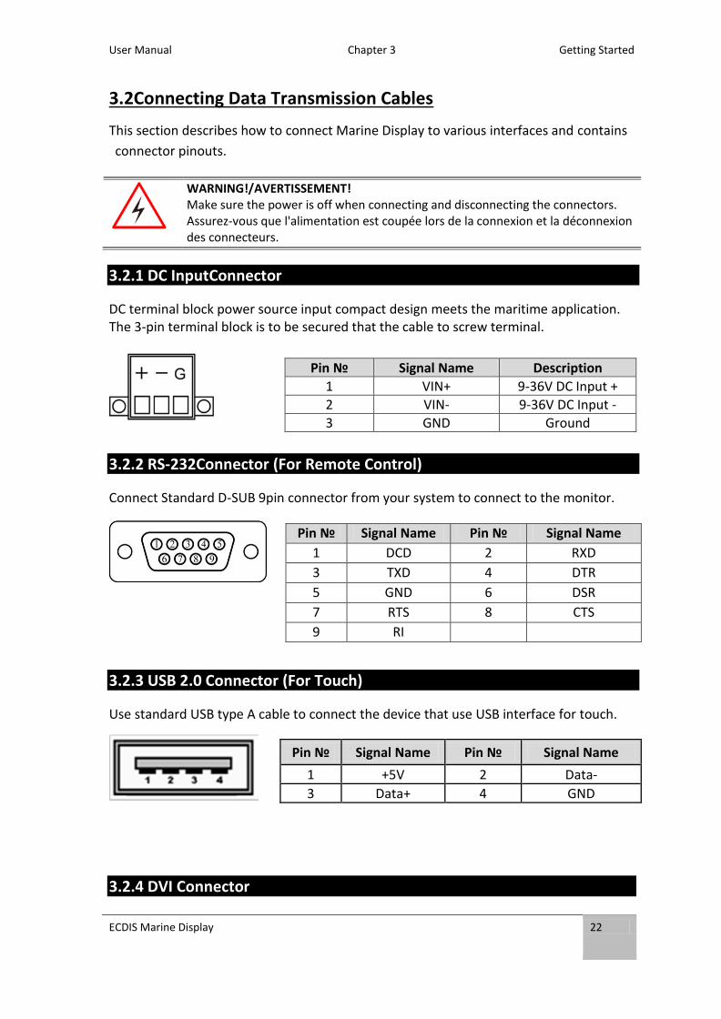
3.2Connecting Data Transmission Cables
This section describes how to connect Marine Display to various interfaces and contains
connector pinouts.
WARNING!/AVERTISSEMENT! Make sure the power is off when connecting and disconnecting the connectors. Assurez-vous que l'alimentation est coupée lors de la connexion et la déconnexion des connecteurs.
3.2.1 DC InputConnector
DC terminal block power source input compact design meets the maritime application. The 3-pin terminal block is to be secured that the cable to screw terminal.
3.2.2 RS-232Connector (For Remote Control)
Connect Standard D-SUB 9pin connector from your system to connect to the monitor.
3.2.3 USB 2.0 Connector (For Touch)
Use standard USB type A cable to connect the device that use USB interface for touch.
3.2.4 DVI Connector
Pin № Signal Name Description
1 VIN+ 9-36V DC Input +
2 VIN- 9-36V DC Input -
3 GND Ground
Pin № Signal Name Pin № Signal Name
1 DCD 2 RXD
3 TXD 4 DTR
5 GND 6 DSR
7 RTS 8 CTS
9 RI
Pin № Signal Name Pin № Signal Name
1 +5V 2 Data-
3 Data+ 4 GND
User Manual Chapter 3 Getting Started
ECDIS Marine Display
23
Use DVI to connector in the rear of PC system,and plug the other end to the TFT LCD display. Fasten cable connectors with screws.
3.2.5 HDMI 1.4 Connector
Use HDMI to connector in the rear of PC system,and plug the other end to the TFT LCD display. Fasten cable connectors with screws.
Pin № Signal Name Pin № Signal Name
1 DVI_RX2- 2 DVI_RX2+
3 GND 4 4-
5 4+ 6 DVI SCL
7 DVI SDA 8 NC
9 DVI_RX1- 10 DVI_RX1+
11 GND 12 3-
13 3+ 14 +5V
15 DVI_CON_CABLE 16 DVI_CON_HP
17 DVI_RX0- 18 DVI_RX0+
19 GND 20 5-
21 5+ 22 GND
23 DVI_CLKP 24 DVI_CLKN
C1 NC C2 NC
C3 NC C4 NC
C5 NC
Pin № Signal Name Pin № Signal Name
1 HDMI_RX2+ 2 GND
3 HDMI_RX2- 4 HDMI_RX1+
5 GND 6 HDMI_RX1-
7 HDMI_RX0+ 8 GND
9 HDMI_RX0- 10 HDMI_RXC+
11 GND 12 HDMI_RXC-
13 HDMI_CON_CEC 14 NC
15 HDMI_CON_SCL 16 HDMI_CON_SDA
17 GND 18 +5V_HDMI
19 HDMI_CON_HP
User Manual Chapter 3 Getting Started
ECDIS Marine Display
24
3.2.6 VGA Connector
ECDIS Marine Display has VGA connector (D-Sub 15pin Female). Use VGA cable to connect the display to the PC system. Fasten cable connectors with screws.
Pin № Signal Name Pin № Signal Name
1 RED 2 GREEN
3 BLUE 4 NC
5 GND 6 RED_RTN
7 GREEN_RTN 8 BLUE_RTN
9 KEY/PWR 10 GND
11 NC 12 SDA
13 H Sync 14 V Sync
15 SCL
User Manual Chapter 3 Getting Started
ECDIS Marine Display
25
3.3 Turning On and Off
This section describes how to turn on or off the ECDIS Marine Display.
3.3.1 Turning On
Press a capacitive power key ( ) until the image appears on the monitor.
IMPORTANT: Make sure the signal source from system is correct (VGA / DVI/ HDMI/ Display Port).
3.3.2 Turning Off the Screen
Press capacitive power button ( ), then the screen turns black.
User Manual Chapter 3 Getting Started
ECDIS Marine Display
26
On-Screen Display (OSD) Control This chapter provides detailed information on how to navigate the On-screen Display (OSD) and how to use the menus to adjust the panel’s image properties.
ECDIS Marine Display
27
4On-Screen Display (OSD) Control
This chapter provides detailed information on how to navigate the On-screen Display (OSD) and how to use the menus to adjust the panel’s image properties.
4.1 OSD Control Key and LED Indicators
Capacitive touch keys and ECDIS mode LED indicators located on the front of your Display.
For more information on OSD control, refer to Ch.1 “OSD Control Keys”and “ECDIS Mode Indicators”of this User Manual.
4.2 OSD Menu Navigation
BRICONTRAST BRIGHTNESS CONTRAST GAMMA
GAMMA0 GAMMA1 GAMMA2
POSITION Only support VGA mode CHANNEL
AUTO ANALOG DVI HDMI
IMAGE Only support VGA mode RECALL YES NO
COLOR
USER 9300K 6500K ADC RIGHTNESS
OSD EXIT YES NO
OP OPTION
ECDIS LED ADJUST VR BRIGH VOLUME ADJUST SPEAK ON/OFF
ECDIS Marine Display
28
4.3 OSD Menu description
BRICONTRAST
OSD icon Sub menu Settings Note
BRICONTRAST
BRIGHTNESS slider bar Default 50
Use to adjust the screen’s brightness.Range 0 to 100
CONTRAST slider bar Default 50
Use to adjust the screen’s contrast. Range 0 to 100
POSITION (VGA mode only)
OSD icon Sub menu Settings Note
POSITION
H POSITION slider bar
Use to adjust the image to the left or right on the screen
V POSITION slider bar
Use to adjust the image up or down on the screen
IMAGE (VGA mode only)
OSD icon Sub menu Settings Note
IMAGE
AUTO Select and execute
Use to choose the best settings for the current input signal
CLOCK slider bar Default 50
Use to adjust the value of horizontal image. Range 0 to 100
PAHSE slider bar Default 50
Use to adjust the phase control (Phase adjustment may be required to optimize the display quality)
WHITE BALANCE Select and execute
Use to set RGB signal voltage level
COLOR
OSD icon Sub menu Settings Note
COLOR
USER R.G.B slider bar
Choose RED/GREEN/BLUE to set value of color temperature brightness to suit you own preference
9300K Select and execute
Use to set value of monitor for the CIE coordinate 9300 color temperature
6500K Select and execute
Use to set value of monitor for the CIE coordinate 6500 color temperature
ADC RIGHTNESS slider bar Default 50
Set value of monitor for ADC Brightness. Range 0 to 100
GAMMA
ECDIS Marine Display
29
OSD icon Sub menu Settings Note
GAMMA
GAMMA 0 Select and execute Default GAMMA0
Choose the parameter of GAMMA 0 as default setting
GAMMA 1 Select and execute
Choose the parameter of GAMMA 1 as default setting
GAMMA 2 Select and execute
Choose the parameter of GAMMA 2 as default setting
OPTION
OSD icon Sub menu Settings Note
OP OPTION
ECDIS DAY MODE DUSK MODE NIGHT MODE
Day / Dusk / Night Mode support ECDIS
LED ADJUST slider bar
Adjust the LED brightness
VR Brightness ON/OFF Default OFF
Choose the brightness control mode by VR control
Volume slider bar Default 10
Use to set value of Volume
Speaker ON/OFF Default 10 OFF
Use to set value of Volume Speaker
CHANNEL
OSD icon Sub menu Settings Note
CHANNEL
AUTO SCAN Select and execute Default mode
Auto detect the input source
ANALOG Select and execute
Switch the setting of signal input to Analog mode
DVI Select and execute
Switch the setting of signal input to DVI mode
HDMI Select and execute
Switch the setting of signal input to HDMI mode
RECALL
OSD icon Sub menu Settings Note
RECALL
YES Select and execute
Recall the factory default setting
NO Select and execute
Return to main menu
ECDIS Marine Display
30
EXIT
OSD icon Sub menu Settings Note
EXIT
YES Select and execute
Exit the OSD menu
NO Select and execute
Return to main menu
ECDIS Marine Display
31
4.4 ECDIS Mode Brightness Adjustment
Winmate provides quickly adjustable Buttons for the ECDIS mode switch (DAY, DUSK ,
NIGHT).
4.3.1 Introduction
Switch the ECDIS mode by tapping capacitive touch key. Tap the ECDIS Mode Quick
Button ( ), and the level of brightness is automatically adjusted according to ECDIS
standard. ECDIS Mode Indicator shows the mode that has been activated.
The sequence of the switching modes is as follows:
DAY Mode→ DUSK Mode → NIGHT Mode → DAY Mode
ECDIS Mode Indicator Capacitive Touch Key
Icon Function Description Touch Key Function Description
Day Mode
Lights up green
when ECDIS
brightness adjusted
to day mode
ECDIS Mode
Quick Button
Switching
ECDIS
standard
range mode
(Day /Dusk /
Night mode)
Dusk
Mode
Lights up green
when ECDIS
brightness adjusted
to dusk mode
Night
Mode
Lights up green
when ECDIS
brightness adjusted
to night mode
ECDIS Marine Display
32
NOTE:
In ECDIS Mode (DAY, DUSK, NIGHT) you can adjust the brightness manually.
Notice when the brightness parameter is above the ECDIS Standard, the LED
indicator light disappears. You should switch the ECDIS mode quick button
again to correct the brightness parameter.
4.3.2 Switching to DAY Mode
4.3.3 Switchingto DUSK Mode
4.3.4 Switching to NIGHT Mode
NIGHT Mode LED Indicator
The brightness also be adjusted to NIGHT Mode
DUSK Mode LED Indicator
The brightness was adjusted toDUSK Mode
DAY Mode
LED Indicator
The brightness was adjusted to DAY Mode
ECDIS Marine Display
33
Maintenance This chapter provides information on regular cleaning and maintenance procedures. Follow all the recommendations included in this chapter in order to ensure long product lifecycle.
User Manual Chapter 5 Maintenance
ECDIS Marine Display
34
5Maintenance
This chapter includes regular cleaning and maintenance procedures. Follow all the recommendations in this chapter in order to ensure long product lifecycle. This equipment is extremely rugged and does not require a lot of maintenance. Remember that electrical equipment should be handled with care and used accordingly to its specifications.
5.1 Cleaning the Display Screen
Wipe the screen with a clean, soft, lint-free cloth. This removes dust and other particles.Do not use acetone, ethyl alcohol, toluene, ethyl acid or methyl chloride to clear the panel. It may permanently damage the display screen.
You can apply a small amount of non-ammonia; non-alcohol based glass cleaner onto a clean, soft, lint-free cloth and wipe the screen.
Never spray or pour any liquid directly on the screen or case.
Do Not use water or oil directly on the display screen. If droplets are allowed to drop on the screen, permanent staining or discoloration may occur.
5.2 Cleaning the Casing
Use the following procedure to clean the equipment.
CAUTION/ ATTENTION Always turn off the device and disconnect other peripherals before cleaning and maintenance procedures. Toujourséteindre l’appareil et débrancher tous les périphériques avant que les procédures de nettoyage et d'entretien.
Before Cleaning:
Make sure the device is turned off.
Disconnect the power cable from any AC outlet.
When Cleaning:
Wipe dust off the outside casing with a cloth slightly moistened with water or mild ammonia-based cleaning solution. Do not use this cloth on a display screen!
Do not use an abrasive cleaner or high pressure washer on the screen.
Do not rub the unit with a dry cloth. This action can result in a static charge being built up and cause a spark. Always use damp cloth while cleaning the unit.
Technical Support This chapter includes directory to our technical
support.
User Manual Chapter 6 Technical Support
ECDIS Marine Display
36
6 Technical Support
This chapter includes troubleshooting guide and problem report form. Free technical support is available from our engineers every business day. We are always ready to give advice on application requirements or specific information on the installation and operation of any of our products.If any problem occurs fill in problem report form enclosed and immediately contact us.
6.1 Troubleshooting
If your monitor fails to operate correctly, consult the following chart for possible solution before calling for repairs:
Condition Check Point
The picture does not appear
Check if the signal cable is firmly seated in the socket. Check if the Power is ON at the computer Check if the brightness control is at the appropriate position,
not at the minimum.
The screen is not synchronized
Check if the signal cable is firmly seated in the socket. Check if the output level matches the input level of your
computer. Make sure the signal timings of the computer system are
within the specification of the monitor. If your computer was working with a CRT monitor, you should
check the current signal timing and turn off your computer before you connect the VGA Cable to this monitor.
The position of the screen is not in the center
Adjust the H-position, and V-position, or Perform the Auto adjustment.
The screen is too bright (too dark).
Check if the brightness or contrast control is at the appropriate position, not at the Maximum (Minimum).
The screen is shaking or waving
Press (the Auto - adjustment control) to adjust. Moving all objects which emit a magnetic field such as motor
or transformer, away from the monitor. Check if the specific voltage is applied.
Check if the signal timing of the computer system is within the specification of monitor.
Note: If you are unable to correct the fault by using this chart, stop using your monitor and contact your distributor or dealer for further assistance.
User Manual Chapter 6 Technical Support
ECDIS Marine Display
37
6.2 Problem Report Form
ECDIS Marine Display (Flat PCAP Touchscreen)
Customer name:
Company:
Tel.: Fax:
E-mail: Date:
Product Serial Number: _____________________________________________________
Problem Description:Please describe the problem as clearly as possible. Detailed
description of the occurred problem will allow us to find the best solution to solve the
Product Specifications This section includes technical specifications of Marine Display
Appendix
User Manual Appendix A Technical Specifications
ECDIS Marine Display
40
Appendix A Technical Specifications
A1 DisplayTechnical Specifications
Model Name R15L600-MRA3FP R19L300-MRA1FP W24L100-MRA1FP W26L100-MRA1FP Display Panel Size 15" 19” 24” 26” Resolution 1024 x 768 1280 x 1024 1920 x 1080 1920 x 1200 Pixel Pitch (H x V, mm)
Touchscreen This section includes information on projected capacitivetouchscreen (PCAP), its technology and specifications. Appendix
User Manual Appendix B PCAP Touchscreen
ECDIS Marine Display
43
Appendix B PCAP Touchscreen
This section includes information on projected capacitive touchscreen (PCAP), its technology and specifications.
B1 Technology Overview
Projected Capacitive Touch (PCAP) technology is a variant of capacitive touch technology. All PCAP touch screens are made up of a matrix of rows and columns of conductive material, layered on sheets of glass.Projected capacitive technology enables touches to be sensed through a protective layer in front of a display, allowing touch monitors to be installed behind store windows or vandal-resistant glass. In addition, the surface material is glass, which is scratch-resistant, durable, and reliable in harsh environments.
The operational theory of a PCAP touch screen begins with two patterned Indium Tin
Oxide (ITO) layers under a glass substrate cover which create a X-axis and Y-axis electric
field. These electric fields project above the glass surface between adjacent ITO traces.
When a finger approaches the glass surface, a new balance in the electric field will be
established between the finger and the corresponding X-axis and Y-axis. The controller
IC will locate the ITO traces exhibiting capacitance changes to pinpoint the finger touch
accurately.
B2 Touchscreen Technical Specifications
Subject Details
Input Method Finger
Positional Accuracy <1.5% of reported position in recommended viewing area.