%, ? WSRC-TR-99-00330 R Reactor Seepage Basins Soil Moisture and Resistivity Field Investigation Using Cone Penetrometer Technology, Savannah River Site, Aiken, South Carolina by M. K. Harris WestinghouseSavannah River Company Savannah River Site Aiken, South Carolina 29808 J. V. Noonkester DOE ContractNo. DE-AC09-96SR1 8500 This paper was prepared in connectionwithwork done underthe above contractnumberwiththe U. S. Departmentof Energy. By acceptanceof this paper, the publisherancf/orrecipientacknowledgesthe U. S, Government’srightto retaina nonexclusive,royalty-freelicensein and to any copyrightcoveringthis paper, along withthe rightto reproduceand to authorizeothersto reproduceall or part of the copyrightedpaper.
Transcript
%, ?
WSRC-TR-99-00330
R Reactor Seepage Basins Soil Moisture and Resistivity FieldInvestigation Using Cone Penetrometer Technology, SavannahRiver Site, Aiken, South Carolina
by
M. K. Harris
WestinghouseSavannah River CompanySavannah River SiteAiken, South Carolina29808
J. V. Noonkester
DOE ContractNo. DE-AC09-96SR1 8500
This paper was prepared in connectionwithwork done underthe above contractnumberwiththe U. S.Departmentof Energy. By acceptanceof this paper, the publisherancf/orrecipientacknowledgesthe U. S,Government’srightto retaina nonexclusive,royalty-freelicensein and to any copyrightcoveringthis paper, alongwiththe rightto reproduceand to authorizeothersto reproduceall or part of the copyrightedpaper.
WSRC-TR-99-O0330Rev. O
R Reactor Seepage Basins Soil Moisture and ResistivityField Investigation using Cone Penetrometer Technology,Savannah River Site, Aiken, South Carolina (U)
Mary K. Harris, Jay V. Noonkester
September 1999
~QoNSIBl[/rkQ$
Prepared by: ● “X4
Westinghouse Savannah River CompanyAA~—~ pm ~—~ cc*- $
Savannah River Site ~ == “~: == ~
Aiken, SC 29808>ZD-AZ- .—
SAVANNAH RIVER SITE
Prepared for the U.S. Department of Energy UnderContract Number DE-AC09-96SR18500 ~
I
ii WSRC-TR-99-O0330, Rev. O,RRSB Soil Moisture and Resistivity Field Investigation with CPT I
DISCLMMER
This report was prepared as an account of work sponsored by an agency of the United StatesGovernment. Neither the United States Government nor any agency thereof, nor any of theiremployees, makes any warranty, express or implied, or assumes any legal liability or responsibilityfor the accuracy, completeness, or usefuhtess of any information, apparatus, product or processdisclosed, or represents that its use would not infringe privately owned rights. Reference herein toany specific commercial product.j process or service by trade name, trademark, manufacturer, orotherwise does not necessarily constitute or imply its endorsement, recommendation, or favoringby the United States Government or any agency thereof. The views and opinions of authorsexpressed herein do not necessarily state or reflect those of the United States Government or anyagency thereof.
This report has been reproduced directiy from the best avaiIable copy.
Available for sale to the public, in paper, from: U.S. Department of Commerce, National TechnicalInformation Service, 5285 Port RoyaJ Road, Springfield, VA 22161, phone: (800) 553-6847fax: (703) 605-6900email: orders@ ntis.fedworld.govonline ordering: http:lAvww.ntis.gov/ordering.htm
Available electronically at http://www.doe.gov/bridgeAvailable for a processing fee to U.S. Department of Energy and its contractors, in paper, from:U.S. Department of Energy, OffIce of ScientMc and Technical Information, P.O. Box 62, OakRidge, TN 37831-0062, phone: (865) 576-8401fax: (865) 576-5728email: reports@ adonis.osti.gov
DISCLAIMER
Portions of this document may be illegiblein electronic image
produced from the
document.
products. Images arebest available original
i
\
WSRC-TR-99-O0330Rev. O
I
BR Reactor Seepage Basins Soil Moisture and Resistivity
I Field Investigation using Cone Penetrometer Technology,Savannah River Site, Aiken, South Carolina (U)
9
Mary K. Harris, Jay V. Noonkester
September 1999
~qoNS181[/pkq..
Prepared by: ● “J+
Westinghouse Savannah River Company44 =—~*= - m—v‘c-D- *
Savannah River Site Jf --= ~: == ~&mma&m
Aiken, SC 29808. -—
SAVANNAH RIVER SITE
Prepared for the U.S. Department of Energy UnderContract Number DE-AC09-96SR18500
ii WSRC-TR-99-O0330, DRAFT, RRSB Soil Moisture and Resistivitv Field Investigation with (2PT
R Reactor Seepage Basins Soil Moisture and Resistivity Field Investigation using Cone
Penetrometer Technology, Savannah River Site, Aiken, South Carolina
Authentication and Approvals:
\z13\ ’17%“
M.K!. Harris, SRTC Date
/24/32
J. V.%oonkester, SRTC i Date
Date
/onnenberg, SRTC, M Date
WSRC-TR-99-O0330, Rev. O, RRSB Soil Moisture and Resistivity Field Investigation with CPT “””111
EXECUTIVE SUMMARY
Recent and historical water table levels at the R Reactor Seepage Basins (RRSBS) suggest
that a “perched” water table may exist directly beneath the RRSBS based on regulatory
documentation and groundwater modeling. Additional studies were conducted in the summer
of 1999 of the shallow groundwater system to determine if the water beneath the RRSBS is
actually perched or whether the shallow water table is in direct communication with the
underlying “transmissive zone”. Direct Push or Cone Penetrometer Technology (CPT) was
used to investigate the shallow water table beneath the basins. CPT soil moisture and
resistivity tests combined with CPT lithologic data (tip, sleeve, friction ratio, and pore
pressure) were performed at 10 locations. The CPT pushes were pushed to approximately
105’ to obtain a saturation profile from the surface to the top of the “transmissive zone” in
the Upper Three Runs Aquifer. Shelby tube samples were taken with the soil moisture
analysis to validate and confirm moisture percentage.
Upon completion of the field investigation the following sources of data were integrated to
determine the characteristics of the shallow water table:
. CPT data (moisture%, resistivity data, pore pressure, tip, sleeve, and friction ratio)
● Permeability data
● Water level and potentiometric data to determine head relations
. Contaminant Data
All the data indicate that perched water conditions occur on a seasonal basis during extremely
wet periods as were experienced in the spring of 1998. There is significantly less mounding
of the water table beneath the RRSBS with water levels being 10–15 feet lower during 1999.
This is due to the “draining” of the upper water table due to dry conditions in the summers of
both 1998 and 1999 along with the effects of the asphalt cover over the basins. CPT data
further indicates that the 1998 water levels were located on top of silty and clayey layers in
March 1998. In addition, the confining-like characteristics of the “A” and “AA” horizons
and the positive potentiometric surface of the underlying “Transrnissive” zone impede
vertical movement of groundwater from the surface to the “transmissive zone”. This
interpretation is corroborated by the extent of Sr-90 contamination in the upper water table
DU zone &d the absence of Sr-90 contamination in the lower DL (“transmissive” zone).
Therefore, contamination from the Principal Threat Source Material (PTSM) associated with
the RRSBS will not easily migrate into the underlying “transmissive zone”.
iv WSRC-TR-99-O0330, Rev. O, RRSB Soil Moisture and Resistivity Field Investigation with CPT
This page intentionally left blank
WSRC-TR-99-O0330, Rev. O, RRSB Soil Moisture and Resistivity Field Investigation with CPT v
1.1 Hydrogeology and Extent of Contamination ..................................................................... 11.2 Field Characterization Methodology using the Cone Penetrometer Soil Moisture &Resistivity Probe ..........................................................................................................................
2.0 Field data acquisition and sampling results ......................................................................... :3.0 Interpretation ......................................................................................................................... 64.0 Summary ................................................................................................................................. 8
Ivi WSRC-TR-99-O0330, Rev. O, RRSB Soil Moisture and Resistivity Field Investigation with CPT
List of Tables and Figures D
Table 1: Name and locations of the RR CPTS.................................................................................................. 3
Table 2: Laboratory Results from RR-3, RR-7, and RR-9 ............................................................................. 5
Figure 1:
Figure 2:
Figure 3:
Figure 4:
Location of the R Reactor Seepage Basins within R Reactor Area. ............................................ 11
Conceptual Hydrogeologic Diagram for the R Reactor Seepage Basins ..................................... 12
Water Table Map – DU screen zone – March 1998, Contour Interval = 5 Ft . ......................... 13
Transmissive zone Potentiometric Surface – DL screen zone – March 1998, Contour Interval=5 Ft . ............................................................................................................................................................ 14
Figure 6: Areal Extent of Contamination illustrating 2 CPT pushes inside fenced area ............................ 16
Figure 7: CPT RR-03 illustrating Friction Ratio, Pore Pressure, Resistivity, and Volume % moisturewith March 1998 and June 1999 water levels from the DU and DL screens of Well RPC-1 .............17
Figure 8: CPT RR-07 iHustrating Friction Ratio, Pore Pressure, Resistivity, and Volume % moisturewith March 1998 and June 1999 water levels from the DU and DL screens of Well RPC-1 .............18
Figure 9: CPT RR-09 illustrating Friction Ratio, Pore Pressure, Resistivity, and Volume YO moisturewith March 1998 and June 1999 water levels from the DU and DL screens of Well RPC-1 .............19
Figure 10: East-West Cross-Section with CPT RR-09, RR-19A, RR-3 illustrating volume % moistureand resistivity CPT curves with March 98 and June 99 DU and DL water elevations plotted.Traverse for cross-section is located on Figure 5....................................... .. .... ................................. ..... 20
Figure 11: Three-dimensional grid of volume percent moisture. Yellow and red area indicate saturatedzone. .......................................................................................................................... ................................. 21
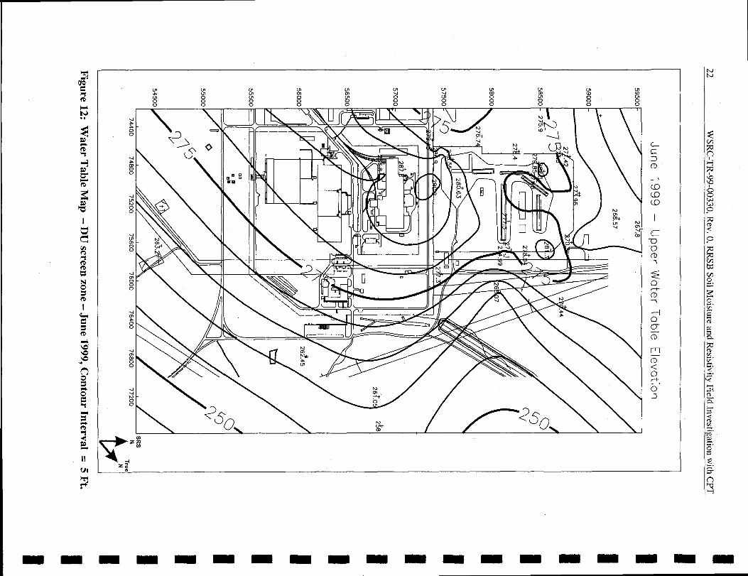
Figure 12: Water Table Map – DU screen zone – June 1999, Contour Interval = 5 Ft . .......................... 22
Figure 13: Transmissive zone Potentiometric Surface – DL screen zone – June 1999, Contour Interval =
WSRC-TR-99-O0330, Rev. O, RRSB Soil Moisture and Resistivity Field Investigation with CFT 1
1.0 Introduction
Recent and historical water table levels at the R Reactor Seepage Basins (RRSBS) (Figure 1)
suggest that a “perched” water table may exist directly beneath the basins. Recent regulatory
documentation (WSRC, 1998) and groundwater modeling (Jones and others, 1998) both
indicated that additional study of the shallow groundwater system is needed to determine if
the water beneath the RRSBS is actually perched or whether the shallow water table is in
direct communication with the underlying “transmissive zone”. The understanding of the
shallow water table in relation to the hydrology of the area is essential for the ongoing
feasibility study for the waste unit. Whether or not the water table is perched may impact the
remedial alternative selection for the Principal Threat Source Material (PTSM). If the water
table is “perched”, then it is part of the soil column above the “Transmissive zone” (which
would become the first viable aquifer zone). If this is the case soil leachability would be
considered from the contaminant source to the “transrnissive zone for the purpose of remedial
technology selection”. The focus of this report is the summer 1999 investigation of the
shallow groundwater system using cone penetrometer technology (CPT) characterization
methods to determine if the water table is perched beneath the RRSBS.
The characterization plan for this study was documented in a Workplan Addendum outlining
additional field characterization for the RRSB Workplan/RFI/RI for the RRSB (WSRC,
1999a).
1.1 Hydrogeology and Extent of Contamination
There are four hydrostratigraphic units that are important to contaminant migration. Figure 2
is a conceptual hydrogeological model for the RRSB area. The seepage basins are located in
undifferentiated surface soils of varying thickness. The “A” and “AA” horizons immediately
beneath the seepage basins, and correspond to the Upland Unit and Tobacco Road Formation.
The “A” and “AA” horizons both are similar to confining units with relatively low hydraulic
conductivities (average 1.Ox10-7 crnlsc and 1.Ox10-6 cmlsec, respectively). The
“Transmissive” zone underlies the “AA” horizon, and correlates to the Irwinton Sand of the
Dry Branch Formation. This zone has relatively high hydraulic conductivity averaging
1.Ox10-4crnlsec.
Groundwater is present in the “A” and “AA” horizons and the “Transmissive” zone. The
hydraulic characteristics of the “A” and “AA” horizons are not well understood because these
strata behave more like confining units than aquifers. The vertical mobility of the
2 WSRC-TR-99-O0330, Rev. O, RRSB Soil Moisture and Resistivity Field Investigation with CPT
groundwater within these low permeability units is also not well understood. Figure 2
illustrates how the groundwater in the “A” and “AA” (DU) horizons is at similar head to the
potentiometric surface of the “Transmissive” zone (DL) to the west of the waste units. This
is supported by the water table surface of the “A/AA” and potentiometric surface of the
“Transrnissive” zone (Figures 3 and 4). In the area underlying the RRSBS the groundwater
surface associated with the “Transmissive” zone (DL) drops toward the “Old” R Area
Discharge Canal, which indicates the aquifer discharges into the canal. However, in the same
area the water table surface associated with the “AlAA” horizon (DU) is relatively flat lying
when compared to the “Transmissive” zone (DL) which suggests minimal connection
between the two water bearing units.
The majority of the Contaminants of Concern (COCS) associated with PTSM have not
migrated significantly within the vadose zone, and tend to remain within the contaminated
soils in the backfilled basins. However, a portion of the Sr-90 associated with the PTSM, has
migrated to the groundwater within the “A” horizon. Am-241, Pu239/240 are also
contaminant migration constituent of concern (CMCOCS) are therefore predicted to migrate
from the PTSM to the groundwater at activities above their respective maximum contaminant
level (MCL). The potential for migration of contaminants in the groundwater within the “A”
horizon, to deeper stratigraphic units, is dependent upon the connection between the water
bearing units. Therefore it is very important to have a good understanding of the hydraulic
characteristics of these hydrostratigraphic units, and the degree of connectivity of the units, to
make good predictions of contaminant transport. In addition, this information is critical to a
proper selection of remedial alternatives.
1.2 Field Characterization Methodology using the Cone Penetrometer Soil Moisture&
Resistivity Probe
Soil Moisture Probes were evaluated at the Savannah River Site in 1996 and 1997 (Argonne
National Laboratory, 1997) through the Site Characterization and Analysis Penetrometer
System. The soil moisture probe is used in conjunction with direct push technology to obtain
real-time data to measure subsurface volumetric soil moisture. Shelby tube samples are taken
with the soil moisture analysis to validate and confirm moisture percentage. In addition,
resistivity log profiles were used in conjunction with the soil moisture percentage
measurements. Based on prior studies conducted at the SRS, the soil moisture percentages
increase as the probe approaches the saturated zone, while the resistivity decreases with the
WSRC-TR-99-O0330, Rev. O, RRSB Soil Moisture and Resistivity Field Investigation with CPT 3
increase in water in the pore space of the sediments (WSRC, 1999, Argonne National Labs,
1997).
CPT soil moisture and resistivity tests combined with CPT lithologic data (tip, sleeve,
friction ratio, and pore pressure) were performed at 10 locations (Figure 5 and Table 1). The
CPT pushes were pushed to approximately 105’ through the undifferentiated surface soils,
“A” Horizon and “AA” Horizon to obtain a saturation profile from the surface to the top of
the “transmissive zone” in the Upper Three Runs Aquifer. The CPT pushes were terminated
at the top of the “Transmissive zone”. Two of the CPT pushes (RR-19A and 19-B) were
inside the RRSB fence (Figure 5), and required RCO/HP coverage. The locations within the
RRSB fenced area were chosen based on the RRSB RFI/RI characterization work that
delineated the extent of contamination (Figure 6). The locations are in non-contaminated
areas within the fence (Figure 5 & 6).
The remaining 8 pushes were completed outside the fence and did not require RCO/HP
coverage (Figure 5). All of the locations are being done near existing lithologic pushes to
maximize hydrogeologic data in the area for interpretive purposes. Shelby tubes were
collected at 3 locations for soil moisture percentage and porosity. Shelby tube samples were
collected, sealed, and stored according to WRSC-3Q5.
I CPT ID I SRSE I SRSN I Elevation II RR-19A I 75349.1 I 57966.3 I 306.63 II RR-19B I 75534.1 I 57887 I 306.63 I
RR-3 75745.5 58111.6 305.7
RR-4 75727.98 58380.3 299.2
I RR-5 I 75609 I 58798.8 I 301.4 IJ
RR-6 75115.7 58891.3 297.8
RR-7 74692.2 58785.6 299.1
RR-8 74657.5 58283.4 299.9
RR-9 74512.2 57895.8 297.6
RR-10 74538.6 57354 291.6
Table 1: Name and locations of the RR CPTS
4 WSRC-TR-99-O0330, Rev. O, RRSB Soil Moisture and Resistivity Field Investigation with CPT
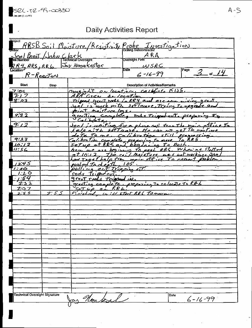
2.0 Field data acquisition and sampling results
Field data acquisition began on 6/14/99 and ended
are reported in Appendix A. Initially, electrical
I9
on 7/1/99. Details of the daily activities
connection problems required repeating Iseveral of the pushes to ensure quality data was collected. Other than the electrical m
malfunctions, the remaining field work went smoothly. Appendix B contains plots of the 10
pushes with sleeve and tip stress, friction ratio, pore pressure, resistivity, and volume percent I
moisture plotted.
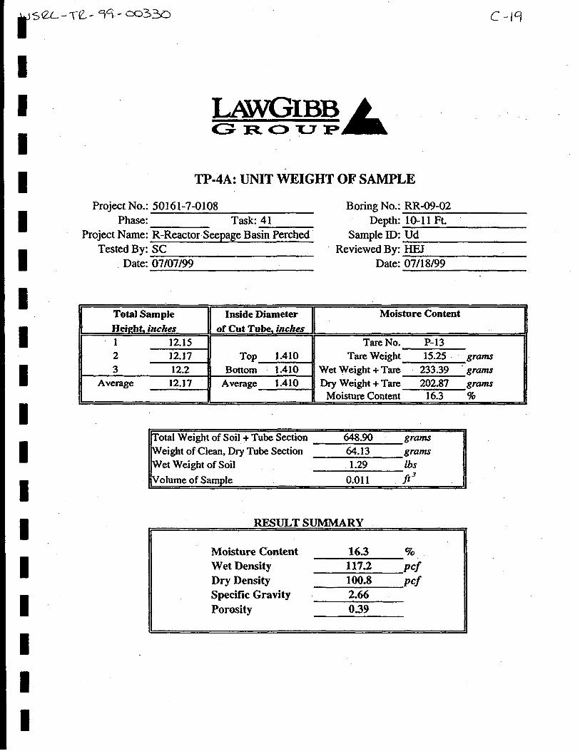
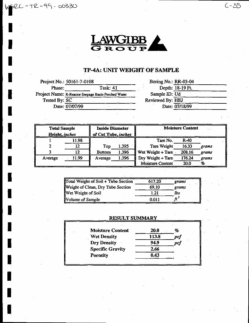
Shelby Tube Samples were collected at RR-3, RR-7, and RR-9. Table 2 summarizes the
results. Figures 7 -9 illustrates the sample locations and percentages in relation to the CPT
data and June water levels at nearby RPC-3 DU and DL. Soil samples were taken in clear B
tubing in four foot sections. The samples were then examined to determine where to take the
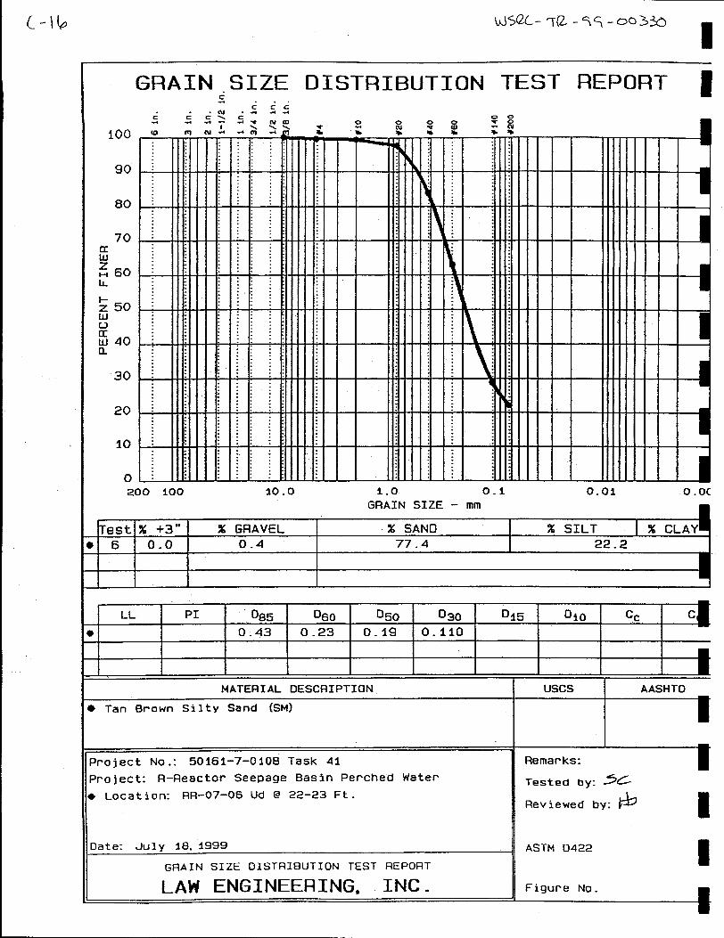
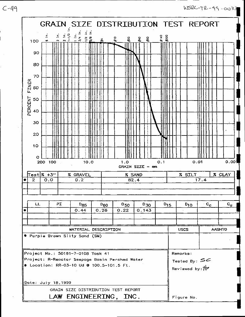
sample based on the CPT results and lithologic type. Samples were analyzed by LAW I
Engineering and Environmental Services in Atlanta, GA for Grain Sieve Wash 200 (ASTM
D422) and volumetric soil moisture content, density and porosity (EM1 110-2-1906). IAppendix C provides the detailed results from LAW Engineering and Environmental
Services.
Samples were taken at RR-3 beginning at a depth of 5 feet. A total of 10 samples were taken
ending at 101.5 feet. Again, samples were taken based on the lithology and in relation to the 9
response on the CPT moisture percentage curve (Figure 7). Generally, the results match well
with the laboratory results and the predicted moisture from the CPT probe. In the upper 30I
feet of RR-3 there is variability of approximately 15% moisture percentage in interbedded
sandy, silty and clayey sediments. In the lower portion of RR-3 the moisture percentage is
relatively stable with variability of approximately 10Yo.
9
WSRC-TR-99-O0330, Rev. O, RRSB Soil Moisture and Resistivity Field Investigation with CPT 5
Sample SRSE SRS N Ground Sample Moisture Wet Dry Spec.
ID Elev. Depth (ft.) Content% Density Density Gravity
WSRC-TR-99-O0330, Rev. O, RRSB Soil Moisture and Resistivity Field Investigation with CPT 17
%.ktik.f:dim-.
U------.--- lmllo
F@me 7: CPT RR-03 illustrating Friction Ratio, Pore Pressure, Resistivity, andVolume % moisture with March 1998 and June 1999 water levels from the DU and DLscreens of Well RPC-1
18 WSRC-TR-99-O0330, Rev. O. RRSB Soil Moisture and Resistivitv Field Investigation with CPT
rest m : RE-07:IIZ: SRS, Aiken SC Soil Moisture and Resistiviky Study;CcAmou : F.-Area
l%~?h?.=1. (cm) P.,, PC,.,.,,
O-----------io U–-–--––----25
~-i–--–––—--.——-—----
—
Pesi..ivity
Cdml-m.
O-------- i833O
vol. !4.13 ,”,,(+)
2-----------1OG
4==June 99
I)L
Figure 8: CPT RR-07 illustrating Friction Ratio, Pore Pressure, Resistivity, andVolume % moisture with March 1998 and June 1999 water levels from the DU and DLscreens of Well RPC-1
WSRC-TR-99-O0330, Rev. O, RRSB Soil Moisture and Resistivity Field Investigation with CPT 19
F@me 9: CPT RR-09 illustrating Friction Ratio, Pore Pressure, Resistivity, andVolume % moisture with March 1998 and June 1999 water levels from the DU and DLscreens of Well RPC-1
------- ------9 -D --
C/l0-!
%
.
. .
Transmkivezane .PatentiametrlcSurface
Moisture
P4Z035.0
? 300
m2s.0
2 C?mg$wrwm’4,0
~igure 11: Three-dimensional grid of volume percent moisture. Yellow and red area indicate saturated zone.
I
c-uw(1)-1
R
WSRC-TR-99-O0330. Rev. O. RRSB Soil Moisture and Resistivitv Field Investigation with CPT 23
June 1999 – Transmissive zone Potentiometric Surface
Figure 13: Transmissive zone Potentiometric Surface – DL screen zone – June 1999,Contour Interval = 5 Ft.
24 WSRC-TR-99-O0330, Rev. O, RRSB Soil Moisture and Resistivity Field Investigation with CPT
REFERENCES
Argonne National Laboratory, Environmental Research Division, 1997, Evaluation Report:
Study of Three Soil Moisture Probes with Laboratoq Sample Results, Version 01, 8129/97,
Environmental Research Division, Argonne National Laboratory, Argonne, Illinois.
Jones, W.F., Haselow, J. S., Harris, M. K., and Denham, M.E., 1998, Groundwater Flow and
Contaminant Transport for the R-Reactor Seepage Basins (U), WSRC-OS-00011, Rev. O
WSRC-TR-99-O0330, Rev.O, RRSB Soil Moisture and Resistivity Field Investigation B-5
3=-
RR-08
a-—-----m +-. I
&6 WSRC-TR-99-O0330, Rev.O . RRSB Soil Moisture and Resistivity Field Investigation9
zolect: 4569!e~t 2D, XE-09
R-Reac tor Saepaa e Basin=: SK, Aikea SC Soil MoLsture and Res i.stivitm studylC1.T206:n-area l~=%?=l
sleeve Stress{tfs} Tip $tless(tfs} Rat10 (CCR)pth 6-----------0
~
-10
-20
-30
-40
-50
-60
-70
-80
-90
-10
0---------480
r
0-----------:
?-
2Pore Pressure <t fs}Rmistivityieh*s)
D---------15 0------1ama
7
I
Vol UOi%mre!%>a----–--mu ekri.
29 Q
Zso
Z70
260
250
240
230
220
210
20u
m: Sxs, Aihn Sc)m.zmil : R-axea
sleeve Sxress!tf3)
lxh-
G
-26
3G
-40
-5C
m
-7e
Em
-90
-:0!
___________~ Tip SZress!Zfs}E---------4CK
——
WSRC-TR-99-O0330, Rev.O, RRSB Soil Moisture and Resistivity Field Investi~ation B-7
!xej.ct: 4569restm: =-19*
~Dsg e BasinI? R?:SRs, Afkem SC Soil ?. foistmre and Resist ivitv studyCx=f2cu:R-rirea ~==ii~——
w hD--
-10
-20
-30
-40
-50
-6CI
-70
-s0
-90
-10
..........- 0 0----–----400
. 13
-2% 1>
R.cio (CcmL?--––-------1O
kRR-19A
‘.05- : 4569 —
M ID: llE-19bme: SSs, - se
. .~
—: E-AX.
Ske.re stress(tfs} Tip stress!tfs} Rs,cio<COWpch 6-----------o a-----–---40D
- m
-2B
-30
-40
-5B
6n
-70
-ED
-90
-1oo
E--------–--1
7!~.2!E_-
Pore Pmsssrefti-l–--------z:
RR-19B
—VOI C+astwe {a
m—-----ma ek .
3m
290
J
2%U
2
Zm
.?53
2ZL?
240
220
220
7?0
D
WSRC-TR-99-00330. Rev. O. RRSB Soil Moisture and Resistivity Field Investigationc-1
mE9B
,9
Appendix C – Shelby Tube Sample Results
c-2 WSRC-TR-99-O0330, Rev. O, RRSB Soil Moisture and Resistivity FieldInvestigation
This page intentionally left blank
C-3
I
99
LAW ~LAWGIBB Group Member
3UIY 23,1999
Westinghouse Savannah River CompanyP.o. Box 616A&q South Carolina 29808
Attention Mr. Bruce TriplettBuilding 730-2B, Room 1086!%dxwntractNO.AB8011 IN
SubjeetTransmittaI of Test Resultx r-Reactor Seepage Basin Perch Water ~GeotechnicalTesting servicesWSRC Site Wide - Taak Release No.41Law Engineering ProjectFIo. 50161-7-0108 (phase 41)
Dear Mr. Triplett
Law Engineering and E&ronmental Servieeq Inc. haa completed the aasigned labomtmy teats fm Taak Release No.41 of our 3-year site-wide geoteebnical testing eontraet. We are transmitting to you the tabular and/or graphicalsummary for each of the speeimens tested. A copy of the Labomtoxy Aaaignment Sheet is enclosed with the samplestested - am the final results, thus, we have enclosed two eopiea of the following test msulta fw yourdiatriiutiom
Grainsizewaah200(AsTM D422)Unit Weight and Porosity(EMl 110-2-WOf$
If you have any questions pertaining to these test results or require additional information%please do not hesitate tocall Us.
Sineen?ly,LAW ENGINEERING and ENVIRONMENTALSERVICES. INC.
$*&’’ffJHan-y E.Principal Techni:an
LAW Engtneermg and Environmental Services. k396 Plasters Avenue ● Atlanta, GA 30324
404-873-4761 ● Fax. 404-881-0508
EsEl
,
-
(
—
—
—
—
—
r
—
—
—
—
b*.
in6
?h0
&K
1
————————.————b
?0
—
*ym~
i%
—
1-
—
—
—
—
—
—
—
1-
—
—
—
—
—
-N
-F—
?:w
—
—
—
—
—
—
—
—.—
—
—
—
—
w.-G-s
—
qm
2a
—
So6t
-Z-OilL-W3 wJmw* (m) =mS Fwwl
f9f M WE3V~d =WM ~
(m) J=wSIwwl
.491HIW.lsv(m) -s ml
Osaz-aWlsv(nn)==S F?*1
Oeos-aWlsv(W@ c)-us Z=J!Cl
Sslz-aWlsvvqss-duq pwgucoun
Mzz-aW.lsv(W*) ~H
Ot!t-a rusvqseM Mets 002w
Zzwbzt-aB.lsvsp~w W+s
Es-O Wlsv4WJ9 W!=$S
elm-a WISv$W?-1-w9122-(3 Wlsv
Wwm @Jw?M
%U ~ MVl5u166ulSqnL
b.
w
-$~mq
a!Ct
{
_
—
1I
—
—.—
. .
+
1-1-
f
—
—
—
i-Lw
bSW
—
—
(lom
[6qmqm w wusqs se)
J-WnN
Projeet No.: 50161-7-0108 Boring No.: RR-07-01
Phase: Task: 41 Depth: 3-4 Ft.
Project Name: R-Reactor Seepage Basin Perehed Sample ID: Ud
Tested By SC Reviewed By: HEJ
Date: 07/07/99 Date: 07/18/99
c-5
TP-4A: LHWT WEIGHT OF SAMPLE
Total Sample II Inside DiameterHeight inches t! of Cut Tuk inches
1 12.14 n
3 12.12 II Bottom 1.409Average 12.12 Average 1.409