American Fiber Cement Corporation R-TEC — The One-Step Engineered Solution for ASHRAE 90.1 Continuous Insulation The R-TEC CI SYSTEM for ventilated rain screen constructions is an engineered solution to enable today’s design professional to meet the ASHRAE 90.1 definition for continuous insulation. Additionally, the R-TEC CI BRACKET is designed to facilitate the use of all types of exterior cladding whether that be metal panels, fiber cement façades or terra cotta tiles. The versatility of the patented R-TEC CI BRACKET affords the flexibility to specify a wide range of exterior insulating materials from mineral wool and lower density foam up to the higher density foams. The R-TEC CI SYSTEM and R-TEC CI BRACKET give the architect the solution for meeting the new performance standards while at the same time controlling costs. Horizontal Bracket Vertical Bracket
Transcript
American FiberCement Corporation
R-TEC — The One-Step Engineered Solution for ASHRAE 90.1 Continuous Insulation
R-TECCISYSTEM™
R-TECCIBRACKET™
The R-TEC CI System for ventilated rain screen constructions is an engineered solution to enable today’s design professional to meet the ASHRAE 90.1 definition for continuous insulation.
Additionally, the R-TEC CI Bracket is designed to facilitate the use of all types of exterior cladding whether that be metal panels, fiber cement façades or terra cotta tiles.
The versatility of the patented R-TEC CI Bracket affords the flexibility to specify a wide range of exterior insulating materials from mineral wool and lower density foam up to the higher density foams.
The R-TEC CI System and R-TEC CI Bracket give the architect the solution for meeting the new performance standards while at the same time controlling costs.
Horizontal Bracket
Vertical Bracket
Metal Stud
1
1
2
7
2
6
3
4
5
Exterior Insulation — High Density Foam
Metal Stud
Exterior Sheathing
Exterior Insulation —Mineral Wool
2
2
6
3
45
Building Wrap
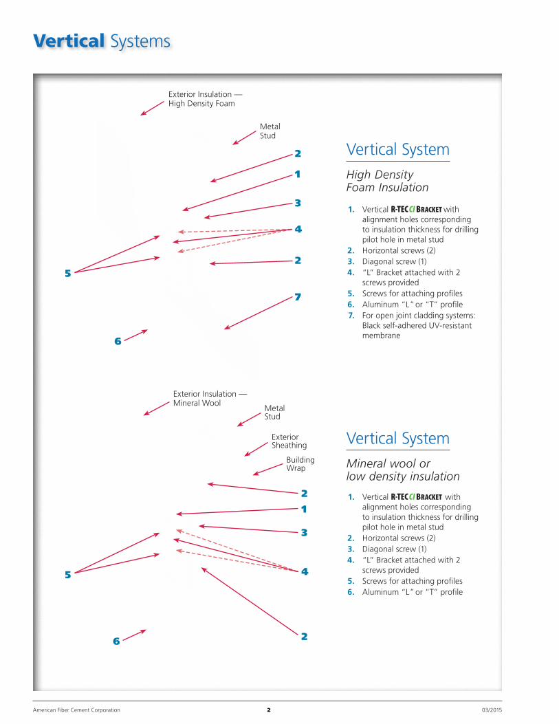
Vertical Systems
American Fiber Cement Corporation 2 03/2015
1. Vertical R-TEC CI Bracket with alignment holes corresponding to insulation thickness for drilling pilot hole in metal stud
to insulation thickness for drilling pilot hole in metal stud
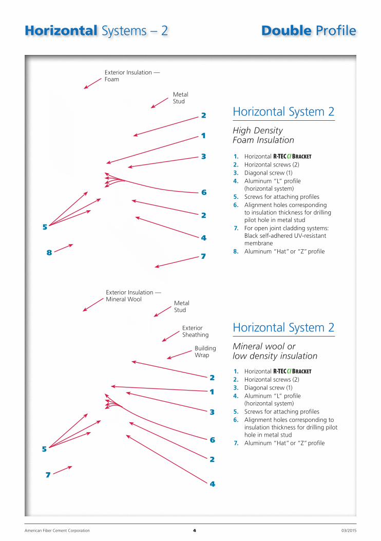
7. For open joint cladding systems: Black self-adhered UV-resistant membrane
8. Aluminum “Hat” or “Z” profile
Horizontal System 2
High Density Foam Insulation
Metal Stud
Metal Stud
Vertical Profile
Vertical Profile
Horizontal Profile
Wallboard
Wallboard
AFC Cladding
AFC Cladding
1
1
5
5
4
2
2
6
6
2
2
3
3
5
7
7
4
R-TECCIBRACKET™
American Fiber Cement Corporation 5 03/2015
1. Horizontal R-TEC CI Bracket 2. Horizontal screws (2) 3. Diagonal screw (1) 4. Screws to attach horizontal profile 5. Rivet/screw to attach vertical profile 6. Alignment holes corresponding to
insulation thickness for drilling pilot hole in metal stud (Alignment holes accommodate insulation of various thicknesses)
7. Exterior insulation
1. Vertical R-TEC CI Bracket 2. Horizontal screws (2) 3. Diagonal screw (1) 4. “L” Bracket attached with 2 screws
provided 5. Screws to attach vertical profile 6. Alignment holes corresponding to
insulation thickness to drill pilot hole in metal stud (Alignment holes accommodate insulation of various thicknesses)
7. Exterior insulation
Typical cross-secTion
Horizontal System 2With 2" High Density Foam Insulation
Typical cross-secTion
Vertical SystemWith 2" High Density Foam Insulation
1. Locate studs behind the exterior insulation. 2. Per the wall layout drawing provided, fasten the
R-TEC Bracket (No. 1) at the specified spacing, both horizontally and vertically. Be careful to ensure the brackets are plumb.
3. Fasten the two horizontal screws (No. 2). Top screw first, then the bottom screw.
4. Locate the correct alignment hole for the insulation thickness specified and drill a pilot hole through the insulation into the wall stud.
5. Install the diagonal screw (No. 3).
6. For vertical systems, attach the "L" bracket (No. 4 on Vertical System illustrations) with two short screws provided.
7. For vertical or horizontal system, attach the remaining specified profiles with the screws/rivets provided. Ensure the profiles are square and plumb. This is easily accomplished utilizing the vertical and horizontal adjustments built into the system design.
8. Attach exterior cladding to the aluminum profiles per the manufacturer's installation instructions
6901 South Pierce Street, Suite 260Littleton, CO 80128 U.S.A.
Phone: 303-978-1199 800-688-8677Fax: 303-978-0308
www.americanfibercement.com
Limited Warranty
American Fiber Cement Corporation (AFCC) warrants that its products are manufactured in accordance with its appli ca ble material specifications and are free from defects in materials and workmanship using AFCC’s specifica-tions as a standard. Only products which are installed and used in accordance with applicable AFCC instructions and specifications are in any way warranted by AFCC. This warranty is applicable only to claims made in writing and received by AFCC within thirty (30) days after the defect was discovered and within ten (10) years after the date of the ship-ment of the product by AFCC. All other claims are waived. If a claim is made, you must allow reason able in vestigation of the pro duct you claim is defective and you must supply samples that ade-quately demonstrate the pro blem you claim for testing by AFCC.
AFCC DISCLAIMS ALL IMPLIED WARRANTIES INCLUDING THE WARRANTY OF MERCHANTABILITY AND THE WARRANTY OF FIT NESS FOR A PARTICULAR PUR POSE. THIS LIMITED WAR RANTY PROVIDES YOUR EXCLU SIVE REMEDY AS A PURCHASER OF AFCC PRODUCTS. THIS LIMIT-ED WARRANTY MAY BE MOD IFIED OR AMENDED ONLY BY A WRIT TEN INSTRUMENT SIGNED BY A DULY AUTHORIZED REPRE SEN TATIVE OF AFCC. WITHOUT AN EXPRESS, WRITTEN AUTHORIZATION FROM AFCC, NO RETAIL ER OR DISTRIBUTOR OF AFCC PRO DUCTS HAS THE AUTHORITY TO MODIFY OR AMEND THIS LIMITED WARRANTY.
Limitation of Liability
This limited warranty is your sole and ex-clusive remedy. It is expressly understood and agreed that the limit of liability will be, at AFCC’s option, repair, re supply of a like quantity of non-defective product, or re fund of purchase price of the mate-rial. All labor and service charges which may be incur red with respect to either the original or replacement pro duct are excluded. AFCC shall have no liability except where the claim results solely from breach of AFCC’s limited warranty.
AFCC SHALL NOT BE LIABLE FOR ANY INCIDENTAL OR CON SEQUENTIAL DAMAGES. FUR THERMORE, AFCC SHALL NOT BE LIABLE FOR DAMAGE TO THE PROPERTY TO WHICH THE PRO DUCT IS APPLIED OR ITS CON-TENTS, LOSS OF TIME, PROFITS, OR ANY INCONVENIENCE ARISING OUT OF ANY BREACH OF THIS LIMITED WARRANTY OR OBLIGATIONS UNDER THIS LIMITED WARRANTY. AFCC SHALL NOT BE LIABLE FOR ANY DAM AGES WHICH ARE BASED UPON NEGLIGENCE, BREACH OF WAR RANTY, STRICT LIABILITY, OR ANY OTHER THEORY EXCEPT THE LIMITED WARRANTY SET FORTH ABOVE. INCIDENTAL AND CONSEQUENTIAL DAM AGES SHALL NOT BE RECOVERABLE EVEN IF THE REPLACEMENT REMEDY FAILS OF ITS PURPOSE OR FOR ANY OTHER REASON.
n Meets the literal definition for ASHRAE 90.1 continuous insulationu Only fasteners penetrate the insulation for minimal
thermal bridgingn Accommodates all types of exterior insulation,
i.e. mineral wool, low density foam or high density foamu Insulation thicknesses can range from 1" to 6."
n Accommodates all types of façadesu Metal – Phenolic – Fiber Cement – Terracotta – Brick
n Aluminum Attachment System for maximum corrosion resistance
n The three design systems provide maximum versatility to control the cost of the building envelope
n Price competitive with all other comparable systems
n The R-TEC CI System includes all of the following elements:u Engineered design for each jobu Static calculationsu Wall layout drawings for bracket locations and detailsu Bracketsu Aluminum profilesu Screws and rivets
n Easily plumbed and leveled due to the alignment features incorporated into the bracket designs
n On-site job assistance is available
n Allows for façades to be either face fastened, glued or back fastened
n CSI 3-PART architectural specs on ARCAT can be downloaded and customized to each project