43
EN0567 Power Machines and Renewable Energy KDU College Penang
| Date post: | 03-Jun-2018 |
| Category: |
Documents |
| Upload: | ejizen-low |
| View: | 236 times |
| Download: | 0 times |

8/12/2019 R03EN0567 Chap03 Transformer
http://slidepdf.com/reader/full/r03en0567-chap03-transformer 1/43
EN0567 Power Machines and Renewable Energy
KDU College Penang

8/12/2019 R03EN0567 Chap03 Transformer
http://slidepdf.com/reader/full/r03en0567-chap03-transformer 2/43
Explain principles of Transformer1
Topic Learning Outcome
Describe types and constructions of Transformer2
Describe the Ideal Transformer and Real Transformer with loses3
Define Transformer Efficiency and Voltage Regulation4
5
6
7
8
EN0567 PM & RW2
Explain Transformer Impedance Transformation
Explain Transformer Equivalent Circuits
Explain Transformer Open and Short Circuit Tests
Tutorial 3

8/12/2019 R03EN0567 Chap03 Transformer
http://slidepdf.com/reader/full/r03en0567-chap03-transformer 3/43
Transformer The transformer is not Electric Machine but is an electrical
device that is closely related. They operates on the same
principles as generators and motors, i.e. actions of magnetic
field.
Transformer converts AC electrical energy at one voltage level
to AC electrical energy at another voltage level.
EN0567 PM & RW3

8/12/2019 R03EN0567 Chap03 Transformer
http://slidepdf.com/reader/full/r03en0567-chap03-transformer 4/43
Use of transformers
Common transformers
EN0567 PM & RW4

8/12/2019 R03EN0567 Chap03 Transformer
http://slidepdf.com/reader/full/r03en0567-chap03-transformer 5/43
Principles of transformer AC (Alternating Current) is selected because it can be readily stepped
(transformed) upward or downward in voltage by means oftransformers.
Transformers are inductances coupled together by their mutual
magnetic fields, or Mutual Inductance. (work by Michael Faraday 1791-1867)
EN0567 PM & RW5

8/12/2019 R03EN0567 Chap03 Transformer
http://slidepdf.com/reader/full/r03en0567-chap03-transformer 6/43
Principles of transformer (contd)
•A varying current in the first or primary winding
creates a varying magnetic flux in the transformer's
core and thus a varying magnetic field through the
secondary winding.
•This varying magnetic field induces a varying
electromotive force (emf), or Voltage in the
secondary winding.
•This effect is called MUTUAL INDUCTION.
EN0567 PM & RW6

8/12/2019 R03EN0567 Chap03 Transformer
http://slidepdf.com/reader/full/r03en0567-chap03-transformer 7/43
Principles of transformer (contd) Definition :
A transformer can be defined as a device that transfer powerfrom its primary circuit to its secondary circuit with very little loss.
Power Line Symbols
EN0567 PM & RW7

8/12/2019 R03EN0567 Chap03 Transformer
http://slidepdf.com/reader/full/r03en0567-chap03-transformer 8/43
Principles of transformer (contd) Lenz’s Law states that the emf induced opposes the changes that produce it.
In other words, the polarity of the induced Voltage is such that the voltage
would produce a current (through an external resistance) that opposes the
original change of flux linkage.
The induced Voltage (V) in a circuit depends upon:a)The amount of flux linkage (λ ), and
b) Rate of change of the flux linkage (dλ /dt )
Note: λ = N.Φ ,where
N is the number of turns of the coil
Φ is magnetic flux (Weber) passing through surface bounded
by the coil.
V = dλ /dt =N.dФ/dt
EN0567 PM & RW8

8/12/2019 R03EN0567 Chap03 Transformer
http://slidepdf.com/reader/full/r03en0567-chap03-transformer 9/43
Principles of transformer (contd)
•When the flux linking a coil changes, avoltage is induced in the coil.
•The polarity of the voltage is such that
if a circuit is formed by placing aresistance across the coil terminals, the
resulting current produces a field that
tends to oppose the original change in
the field.
Note: B is Magnetic Flux Density,
which is defined as flux per unit area.
Unit measurement is Tesla or Weber/m2.EN0567 PM & RW9

8/12/2019 R03EN0567 Chap03 Transformer
http://slidepdf.com/reader/full/r03en0567-chap03-transformer 10/43
Construction of transformer
A simple transformer consists of two windings verytightly coupled together, usually with an iron core, but
electrically insulated from each other.
It is desirable to get the magnetic flux coupling betweenthe two windings as high as possible.
The degree of coupling is called coupling efficiency. i.e.
how many percent of the flux lines from the primarywinding cut the secondary winding.
EN0567 PM & RW10

8/12/2019 R03EN0567 Chap03 Transformer
http://slidepdf.com/reader/full/r03en0567-chap03-transformer 11/43
Construction of transformer
Iron Core has a relative permeability (µr) in the
order of 5000 to 6000 times compares to Air.EN0567 PM & RW11

8/12/2019 R03EN0567 Chap03 Transformer
http://slidepdf.com/reader/full/r03en0567-chap03-transformer 12/43
Construction of transformer (contd) Both coils are usually wound on an iron core so that
the path of the flux lines can be controlled and kept
where desired. A special alloy of silicon steel is
commonly used for transformer cores.
Types of core:
EN0567 PM & RW12

8/12/2019 R03EN0567 Chap03 Transformer
http://slidepdf.com/reader/full/r03en0567-chap03-transformer 13/43
Construction of transformer (contd)
Small
Transformer
Power
Transformer
AutoTransformer EN0567 PM & RW13
8/12/2019 R03EN0567 Chap03 Transformer
http://slidepdf.com/reader/full/r03en0567-chap03-transformer 14/43
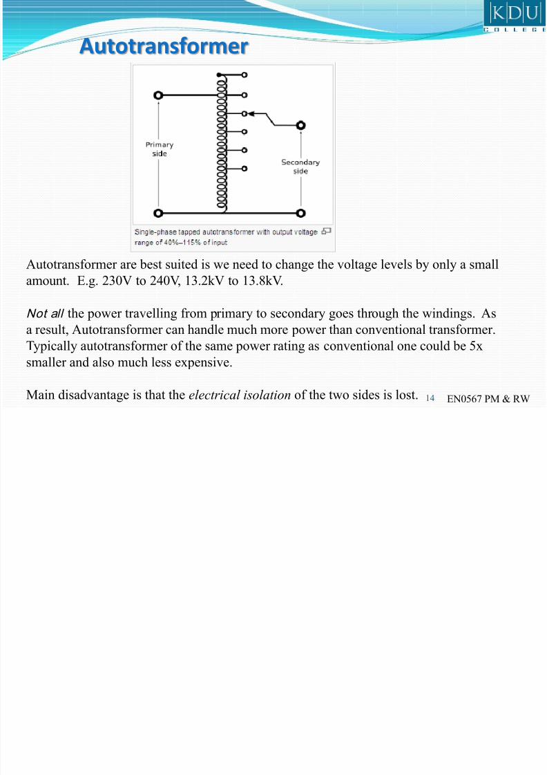
Autotransformer
Autotransformer are best suited is we need to change the voltage levels by only a small
amount. E.g. 230V to 240V, 13.2kV to 13.8kV.
Not all the power travelling from primary to secondary goes through the windings. As
a result, Autotransformer can handle much more power than conventional transformer.
Typically autotransformer of the same power rating as conventional one could be 5x
smaller and also much less expensive.
Main disadvantage is that the electrical isolation of the two sides is lost. EN0567 PM & RW14

8/12/2019 R03EN0567 Chap03 Transformer
http://slidepdf.com/reader/full/r03en0567-chap03-transformer 15/43
Autotransformer
Step-down Step-up
EN0567 PM & RW15

8/12/2019 R03EN0567 Chap03 Transformer
http://slidepdf.com/reader/full/r03en0567-chap03-transformer 16/43
Construction of transformer (contd)
•It is possible to use 3 single-phase transformers or one common-core three-phase transformer.
•The latter saves space and cost but not flexible and gives higher down-time.
http://upload.wikimedia.org/wikipedia/commons/3/3b/Three-phase_transformer_EI_core_flux_animation_full_pulse.gif
EN0567 PM & RW16
8/12/2019 R03EN0567 Chap03 Transformer
http://slidepdf.com/reader/full/r03en0567-chap03-transformer 17/43
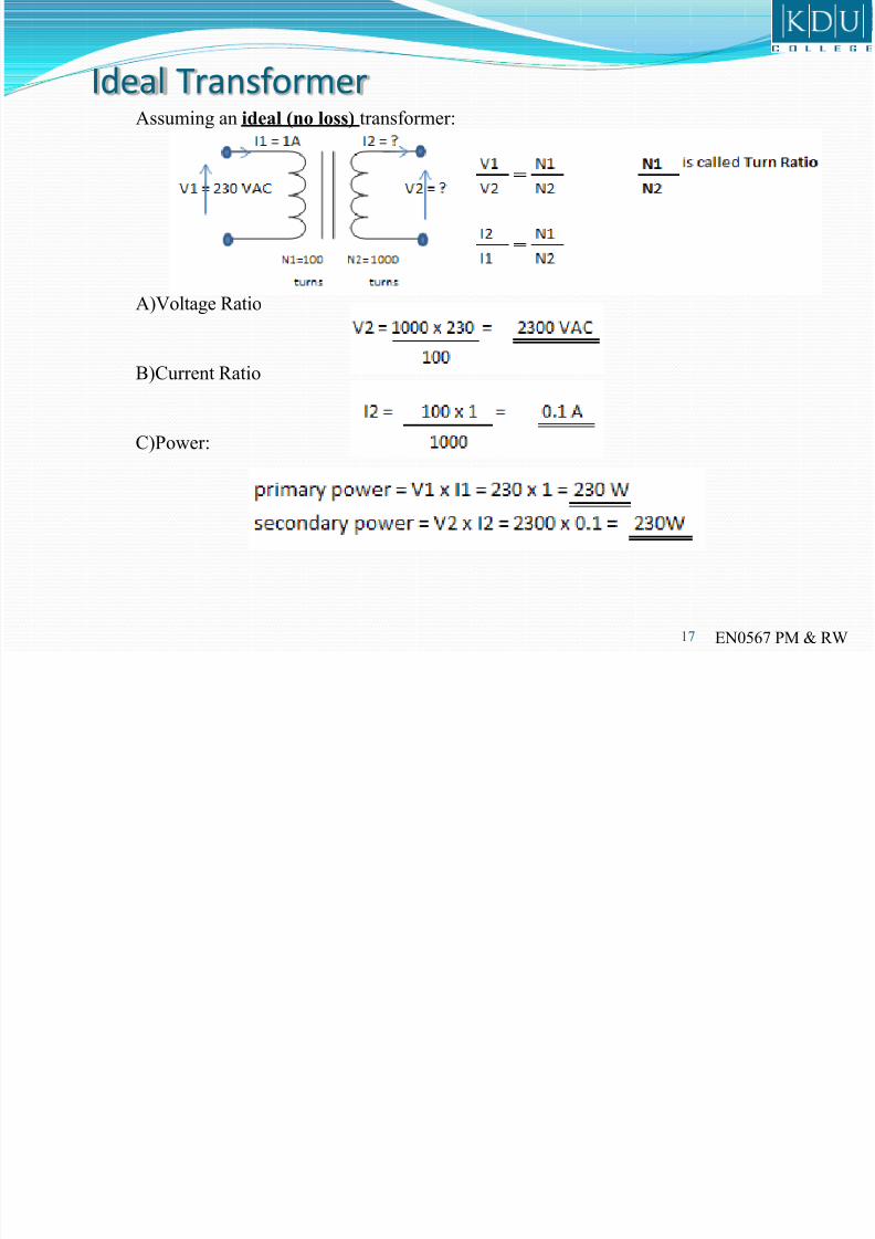
Ideal Transformer Assuming an ideal (no loss) transformer:
A)Voltage Ratio
B)Current Ratio
C)Power:
EN0567 PM & RW17
8/12/2019 R03EN0567 Chap03 Transformer
http://slidepdf.com/reader/full/r03en0567-chap03-transformer 18/43
Transformer Losses
1. Copper Loss : Loss from resistance of (copper) wire in windings of
transformer. L= I²R
2. Flux Leakage Loss: flux lines that leak from windings or core such
that they do not link between primary and secondary.
3. Hysteresis Loss: When current reverses, there is energy needed to
reverse the magnetic alignment of the core. This energy is not
available in the secondary, hence loss.
4. Eddy Current Loss: The core of the transformer conducts electricityand acts like a single-turn shorted secondary. This effect can be
minimized by using high resistivity material and laminating the core.
Note: items 3 and 4 are called Iron Loss
EN0567 PM & RW18

8/12/2019 R03EN0567 Chap03 Transformer
http://slidepdf.com/reader/full/r03en0567-chap03-transformer 19/43
Transformer Efficiency
Note that a transformer operating at full load is one that is delivering into a load the
specified Volt-Amperes; Actual Output Power will depend on the power factor.
EN0567 PM & RW19

8/12/2019 R03EN0567 Chap03 Transformer
http://slidepdf.com/reader/full/r03en0567-chap03-transformer 20/43
Transformer Voltage Regulation
The secondary voltage of a transformer decreases as the load
is increased, because of the increase of the losses that occur.
%100 X
V
V V VR
load full
load full load no
EN0567 PM & RW20

8/12/2019 R03EN0567 Chap03 Transformer
http://slidepdf.com/reader/full/r03en0567-chap03-transformer 21/43
Impedance Transformation
Thus a transformer added in between the source and load
alters the apparent impedance of the load. This is useful for
Impedance Matching for maximum power transfer.
EN0567 PM & RW21

8/12/2019 R03EN0567 Chap03 Transformer
http://slidepdf.com/reader/full/r03en0567-chap03-transformer 22/43
Transformer Equivalent Circuits
Full
EN0567 PM & RW22

8/12/2019 R03EN0567 Chap03 Transformer
http://slidepdf.com/reader/full/r03en0567-chap03-transformer 23/43
Transformer Equivalent Circuits
Exact
Sim plified
EN0567 PM & RW23

8/12/2019 R03EN0567 Chap03 Transformer
http://slidepdf.com/reader/full/r03en0567-chap03-transformer 24/43
8/12/2019 R03EN0567 Chap03 Transformer
http://slidepdf.com/reader/full/r03en0567-chap03-transformer 25/43
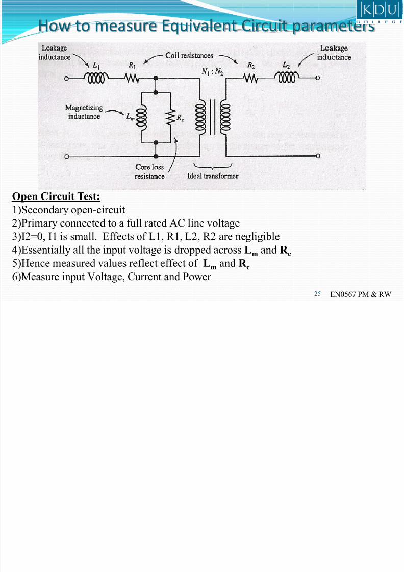
How to measure Equivalent Circuit parameters
Open Circuit Test:
1)Secondary open-circuit2)Primary connected to a full rated AC line voltage
3)I2=0, I1 is small. Effects of L1, R1, L2, R2 are negligible
4)Essentially all the input voltage is dropped across Lm and R c
5)Hence measured values reflect effect of Lm and R c6)Measure input Voltage, Current and Power
EN0567 PM & RW25

8/12/2019 R03EN0567 Chap03 Transformer
http://slidepdf.com/reader/full/r03en0567-chap03-transformer 26/43
Open Circuit Test
EN0567 PM & RW26
8/12/2019 R03EN0567 Chap03 Transformer
http://slidepdf.com/reader/full/r03en0567-chap03-transformer 27/43
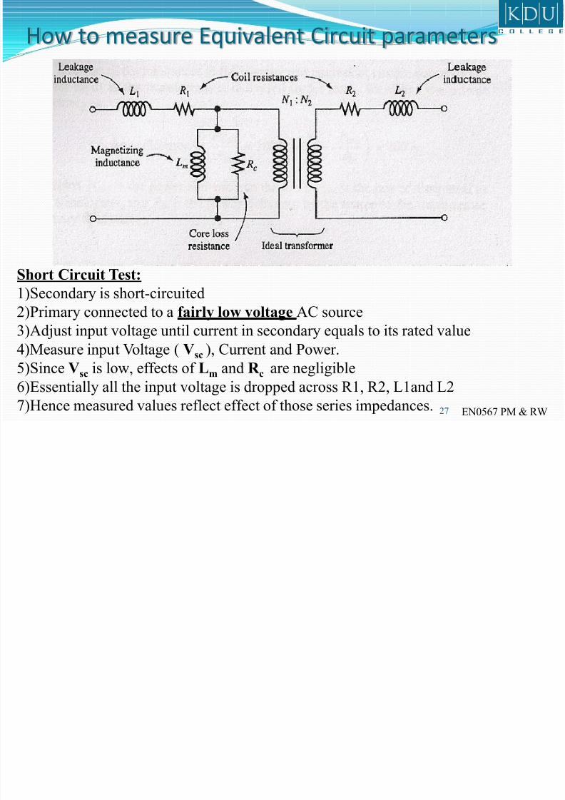
How to measure Equivalent Circuit parameters
Short Circuit Test:
1)Secondary is short-circuited2)Primary connected to a fairly low voltage AC source
3)Adjust input voltage until current in secondary equals to its rated value
4)Measure input Voltage ( Vsc ), Current and Power.
5)Since Vsc is low, effects of Lm and R c are negligible
6)Essentially all the input voltage is dropped across R1, R2, L1and L2
7)Hence measured values reflect effect of those series impedances. EN0567 PM & RW27

8/12/2019 R03EN0567 Chap03 Transformer
http://slidepdf.com/reader/full/r03en0567-chap03-transformer 28/43
Short Circuit Test
EN0567 PM & RW28

8/12/2019 R03EN0567 Chap03 Transformer
http://slidepdf.com/reader/full/r03en0567-chap03-transformer 29/43
Example: The equivalent circuit impedances of a 20-kVA, 8000/240-
V, 60-Hz transformer are to be determined. The open-circuit test and
the short-circuit test were performed on the primary side of thetransformer, and the following data were taken:
Find the impedances of the approximate equivalent circuit referred
to the primary side, and sketch that circuit.
EN0567 PM & RW29

8/12/2019 R03EN0567 Chap03 Transformer
http://slidepdf.com/reader/full/r03en0567-chap03-transformer 30/43
EN0567 PM & RW30

8/12/2019 R03EN0567 Chap03 Transformer
http://slidepdf.com/reader/full/r03en0567-chap03-transformer 31/43
EN0567 PM & RW31
8/12/2019 R03EN0567 Chap03 Transformer
http://slidepdf.com/reader/full/r03en0567-chap03-transformer 32/43
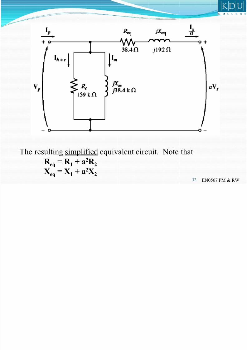
The resulting simplified equivalent circuit. Note that
R eq = R 1 + a2R 2
Xeq = X1 + a2
X2EN0567 PM & RW32
8/12/2019 R03EN0567 Chap03 Transformer
http://slidepdf.com/reader/full/r03en0567-chap03-transformer 33/43
Transformer is suited for power source transformation
In power systems, transformers are mainly used to step-up the
voltage to levels suitable for transmission or distribution and to step
down to levels as required by individual consumers.
For the same power flow, increasing the voltage by m-times itsformer value reduces the current flow to (1/m) its former value.
Hence, voltage drop (IZ) and power loss (I2R ) are reduced to (1/m)
and (1/m2) times the former values, respectively.
EN0567 PM & RW33

8/12/2019 R03EN0567 Chap03 Transformer
http://slidepdf.com/reader/full/r03en0567-chap03-transformer 34/43
Transformer is suited for power source transformation
Applications of transformers:(i)Change voltage level: e.g. generator transformer 20 kV to 400
kV, distribution transformer 11 kV to 400V three-phase and 230V
single-phase, rectifier transformer to set DC level at rectifier output.
(i)‘Safety’ applications: i.e. step voltage down to a safe level and‘isolate’ or separate secondary side from primary side. Also, the
neutral point of a star connected three-phase winding provides an
earthing point.
(i)Matching of voltage magnitude, phase or impedance: e.g.
applications which require connection of different circuits operating
independently.
EN0567 PM & RW34

8/12/2019 R03EN0567 Chap03 Transformer
http://slidepdf.com/reader/full/r03en0567-chap03-transformer 35/43
Question & Answer Session
EN0567 PM & RW35

8/12/2019 R03EN0567 Chap03 Transformer
http://slidepdf.com/reader/full/r03en0567-chap03-transformer 36/43
Tutorial 3: Q1: A single-phase power system is shown below. The power source feeds a
100-kVA 14/2.4-kV transformer through a feeder impedance of 40.0 + j 150Ω . The
transformer's equivalent series impedance referred to its low-voltage side is 0. 12 +
j0.5Ω. The load on the transformer is 90 kW at 0.85 PF lagging and 2300 V.
(a) What is the voltage at the power source of the system?
(b) What is the voltage regulation of the transformer?
(c) How efficient is the overall power system?
EN0567 PM & RW36

8/12/2019 R03EN0567 Chap03 Transformer
http://slidepdf.com/reader/full/r03en0567-chap03-transformer 37/43
Tutorial 3: Solution to Q1 (a):
EN0567 PM & RW37

8/12/2019 R03EN0567 Chap03 Transformer
http://slidepdf.com/reader/full/r03en0567-chap03-transformer 38/43
Tutorial 3: Solution to Q1 (b) & (c):
EN0567 PM & RW38

8/12/2019 R03EN0567 Chap03 Transformer
http://slidepdf.com/reader/full/r03en0567-chap03-transformer 39/43
Tutorial 3:
Q2: A 13.2 kV single-phase generator supplies power to a load through a
transmission line. The load's impedance is Zload = 500 36.87 o , , and thetransmission line's impedance is Zline = 60 53 .1o , .
(a) If the generator is directly connected to the load (Figure next page), what is the ratio
of the load voltage to the generated voltage? What are the transmission
losses of the system?(b) If a 1:10 step-up transformer is placed at the output of the generator and a 10: 1
transformer is placed at the load end of the transmission line, what is the new
ratio of the load voltage to the generated voltage? What are the transmission
losses of the system now? (Note: The transformers may be assumed to be ideal.)
EN0567 PM & RW39

8/12/2019 R03EN0567 Chap03 Transformer
http://slidepdf.com/reader/full/r03en0567-chap03-transformer 40/43
Tutorial 3:
EN0567 PM & RW40
8/12/2019 R03EN0567 Chap03 Transformer
http://slidepdf.com/reader/full/r03en0567-chap03-transformer 41/43
Tutorial 3: Solution to Q2 (a):
EN0567 PM & RW41
8/12/2019 R03EN0567 Chap03 Transformer
http://slidepdf.com/reader/full/r03en0567-chap03-transformer 42/43
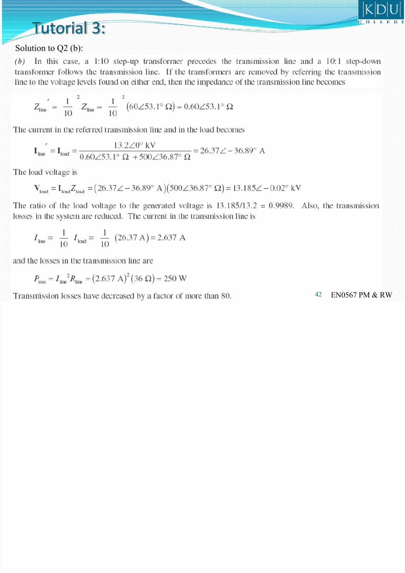
Tutorial 3: Solution to Q2 (b):
EN0567 PM & RW42
8/12/2019 R03EN0567 Chap03 Transformer
http://slidepdf.com/reader/full/r03en0567-chap03-transformer 43/43


