63
PowerEdge R415 Technical Guide The PowerEdge R415 offers enterprise-class features with a balance of processing power and value.

8/14/2019 r415 Tech Guide 11-18-10_final
http://slidepdf.com/reader/full/r415-tech-guide-11-18-10final 1/63
PowerEdge R415Technical Guide
The PowerEdgeR415 offersenterprise-classfeatures with a
balance ofprocessing power
and value.

8/14/2019 r415 Tech Guide 11-18-10_final
http://slidepdf.com/reader/full/r415-tech-guide-11-18-10final 2/63
Dell
i
PowerEdge R415 Technical Guide
This document is for informational purposes only. Dell reserves the right to make changes without furthernotice to any products herein. The content provided is as is and without express or implied warranties ofany kind.
Dell, PowerEdge, OpenManage, and ReadyRails are trademarks of Dell, Inc. AMD, AMD Opteron, AMDPowerNow!, CoolCore, and combinations thereof are trademarks of Advanced Micro Devices, Inc. Citrix® andXenServerTM are trademarks of Citrix Systems, Inc. and/or one or more of its subsidiaries, and may be
registered in the United States Patent and Trademark Office and in other countries. Intel and Xeon areregistered trademarks of Intel Corporation in the U.S. and other countries. Broadcom is a registeredtrademark of Broadcom Corporation and/or its affiliates in the United States, certain other countries and/orthe EU. Matrox is a registered trademark of Matrox Electronic Systems Ltd. Microsoft, Windows, WindowsServer, SQL Server, BitLocker, and Hyper-V are either registered trademarks or trademarks of MicrosoftCorporation in the United States and/or other countries. Nuvoton is a registered trademark of NuvotonTechnology Corporation. Red Hat is a registered trademark of Red Hat, Inc. in the United States and othercountries. Linux is a registered trademark of Linus Torvalds. QLogic is a registered trademark of QlogicCorporation. VMware and ESX are registered trademarks and vSphere and ESXi are trademarks of VMware,Inc. in the United States and/or other jurisdictions. Other trademarks and trade names may be used in thisdocument to refer to either the entities claiming the marks and names or their products. Dell disclaimsproprietary interest in the marks and names of others.
©Copyright 2010 Dell Inc. All rights reserved. Reproduction or translation of any part of this work beyondthat permitted by U.S. copyright laws without the written permission of Dell Inc. is unlawful and strictlyforbidden.
November 2010

8/14/2019 r415 Tech Guide 11-18-10_final
http://slidepdf.com/reader/full/r415-tech-guide-11-18-10final 3/63
Dell
ii
PowerEdge R415 Technical Guide
Table of Contents
1 Product Comparison ........................................................................................... 7 1.1 Overview .................................................................................................. 7
1.1.1 Designed to Go the Distance ..................................................................... 7 1.1.2 Efficient from the Inside Out .................................................................... 7 1.1.3 Easy to Manage ..................................................................................... 7 1.2 Comparison ............................................................................................... 8
2 System Overview ............................................................................................. 11 3 Mechanical .................................................................................................... 14
3.1 Chassis Description ..................................................................................... 14 3.2 Dimensions and Weight ................................................................................ 14 3.3 Front Panel View and Features ....................................................................... 15 3.4 Back Panel View and Features ........................................................................ 15 3.5 Power Supply Indicators ............................................................................... 16 3.6 NIC Indicators ........................................................................................... 16 3.7 Side Views ............................................................................................... 16 3.8 Internal Chassis View .................................................................................. 17 3.9 Rails and Cable Management ......................................................................... 17 3.9.1 ReadyRails Sliding Rails .......................................................................... 17
3.9.2 ReadyRails Static Rails ........................................................................... 17 3.10 Rack View ................................................................................................ 18
3.10.1 Sliding Rails ........................................................................................ 18 3.10.2 Static Rails ......................................................................................... 18
3.11 Fans ....................................................................................................... 19 3.12 Control Panel ............................................................................................ 19
3.12.1 LED Panel Configuration ......................................................................... 20 3.12.2 LCD Panel Configuration ......................................................................... 20
3.13 Security .................................................................................................. 21 3.13.1 Cover Latch ........................................................................................ 21 3.13.2 Bezel................................................................................................ 21 3.13.3 Hard Drive ......................................................................................... 21 3.13.4 Trusted Platform Module (TPM) ................................................................ 21 3.13.5 Power Off Security ............................................................................... 21 3.13.6 Intrusion Alert ..................................................................................... 21 3.13.7 Secure Mode ....................................................................................... 22
3.14 USB Key .................................................................................................. 22 3.15 Battery ................................................................................................... 22 3.16 Field Replaceable Units (FRU) ........................................................................ 22 3.17 User Accessible Jumpers, Sockets, and Connectors ............................................... 22
4 Power, Thermal, Acoustic ................................................................................... 23 4.1 Power Supplies .......................................................................................... 23 4.2 Power Supply Specifications .......................................................................... 23 4.3 Heat Dissipation ........................................................................................ 24 4.4 Environmental Specifications ......................................................................... 24 4.5 ENERGY STAR® Compliance ........................................................................... 25 4.6 Thermal .................................................................................................. 25 4.7 Acoustics ................................................................................................. 25
5 Processors ..................................................................................................... 27 5.1 Overview ................................................................................................. 27
8/14/2019 r415 Tech Guide 11-18-10_final
http://slidepdf.com/reader/full/r415-tech-guide-11-18-10final 4/63
Dell
iv
PowerEdge R415 Technical Guide
5.2 Features ................................................................................................. 27 5.3 Supported Processors .................................................................................. 27 5.4 Processor Configurations .............................................................................. 28 5.5 Processor Installation .................................................................................. 28
6 Memory ........................................................................................................ 29 6.1 Overview ................................................................................................. 29 6.2 DIMMs Supported ....................................................................................... 29 6.3 DIMM Slots ............................................................................................... 29 6.4 Speed ..................................................................................................... 30 6.5 Sparing ................................................................................................... 30 6.6 Mirroring ................................................................................................. 30 6.7 RAID ...................................................................................................... 30 6.8 Supported Configurations ............................................................................. 30
7 Chipset ......................................................................................................... 32 7.1 Overview ................................................................................................. 32 7.2 AMD I/O Bridges ........................................................................................ 32 7.3 HyperTransport 3 (HT3) ............................................................................... 32 7.4 Southbridge Link Interface ............................................................................ 32 7.5 AMD SP5100 Southbridge (SP5100) ................................................................... 32
8 BIOS ............................................................................................................ 33 8.1 Overview ................................................................................................. 33 8.2 Supported ACPI States ................................................................................. 34 8.3 Power Management Modes ............................................................................ 34
8.3.1 Dell Active Power Controller .................................................................... 34 8.3.2 Power Saving BIOS Setting (OS Control) ....................................................... 34 8.3.3 Maximum Performance .......................................................................... 34
9 Embedded NICs/LAN on Motherboard (LOM) ............................................................. 37 10 I/O Slots ....................................................................................................... 38
10.1 Overview ................................................................................................. 38 10.2 Boot Order ............................................................................................... 40 10.3 NICs ....................................................................................................... 40 10.4 NIC and LOM Enumeration ............................................................................. 40 10.5 PCI Card Dimensions ................................................................................... 40
11 Storage ......................................................................................................... 41 11.1 Overview ................................................................................................. 41 11.2 RAID Configurations .................................................................................... 41 11.3 Persistent Storage ...................................................................................... 43 11.4 Internal SD Module (Unmanaged Internal Persistent Storage) ................................... 43 11.5 LED Indicators ........................................................................................... 44 11.6 Optical Drives ........................................................................................... 44 11.7 Tape Drives .............................................................................................. 44 11.8 External Storage ........................................................................................ 44
12 Video ........................................................................................................... 45 13 Rack Information ............................................................................................. 46 13.1 Overview ................................................................................................. 46
13.2 Rails ...................................................................................................... 46 13.2.1 Sliding Rails ........................................................................................ 46 13.2.2 Static Rails ......................................................................................... 47
13.3 Cable Management Arm (CMA) ....................................................................... 49 14 Operating Systems and Virtualization ..................................................................... 50 15 Systems Management ........................................................................................ 51
8/14/2019 r415 Tech Guide 11-18-10_final
http://slidepdf.com/reader/full/r415-tech-guide-11-18-10final 5/63
Dell
v
PowerEdge R415 Technical Guide
15.1 Overview/Description .................................................................................. 51 15.2 Server Management .................................................................................... 51 15.3 Embedded Server Management ....................................................................... 51 15.4 Lifecycle Controller and Unified Server Configurator ............................................. 52 15.5 iDRAC Express ........................................................................................... 52 15.6 iDRAC6 Enterprise ...................................................................................... 53
16 USB Peripherals ............................................................................................... 55 Appendix A. Statement of Volatility ....................................................................... 56 Appendix B. Certifications ................................................................................... 60
B.1 Regulatory Certifications .............................................................................. 60 B.2 Product Safety Certifications ......................................................................... 60 B.3 Electromagnetic Compatibility ....................................................................... 61 B.4 Ergonomics, Acoustics and Hygienics ................................................................ 61
Appendix C. Additional Information and Options ......................................................... 62
Tables
Table 1. Feature Comparison to SC1435, R410, and R610 ................................................. 8
Table 2. Product Features Summary ........................................................................ 11 Table 3. Power Supply Status ................................................................................. 16 Table 4. Power Supply Specifications ....................................................................... 23 Table 5. Heat Dissipation ..................................................................................... 24 Table 6. Environmental Specifications ...................................................................... 24 Table 7. Acoustical Performance ............................................................................ 26 Table 8. Supported Processor Description and Features ................................................. 27 Table 9. DIMMS Supported .................................................................................... 29 Table 10. Supported Configurations (1 Processor) .......................................................... 30 Table 11. Supported Configurations (2 Processors) ......................................................... 31 Table 12. BIOS Power Management Features ................................................................ 34 Table 13. BIOS Power Management Profiles ................................................................. 35
Table 14. Supported Expansion Cards ........................................................................ 38 Table 15. Supported Hard Drives .............................................................................. 41 Table 16. RAID Configurations ................................................................................. 41 Table 17. Graphics Video Modes ............................................................................... 45 Table 18. Supported Racks ..................................................................................... 48 Table 19. Rail Adjustability Ranges and Depth .............................................................. 49 Table 20. Unified Server Configurator Features and Description ......................................... 52 Table 21. Features List for BMC, iDRAC, and vFlash ........................................................ 53 Table 22. R415 Volatility Table ................................................................................ 56 Table 23. Product Safety Certifications ...................................................................... 60 Table 24. Electromagnetic Compatibility Certifications ................................................... 61 Table 25. Ergonomics, Acoustics and Hygienics ............................................................. 61
Table 26. Industry Standards ................................................................................... 62
Figures
Figure 1. R415 Chassis Dimensions............................................................................ 14 Figure 2. Front View (Cabled HDD with LED)................................................................ 15 Figure 3. Front View (Hot-Plug HDD with LCD) ............................................................. 15 Figure 4. Front View (With Optional Bezel) ................................................................. 15 Figure 5. Back View (Non-Redundant Power Supply) ...................................................... 15

8/14/2019 r415 Tech Guide 11-18-10_final
http://slidepdf.com/reader/full/r415-tech-guide-11-18-10final 6/63
Dell
v
PowerEdge R415 Technical Guide
Figure 6. Back View (Redundant Power Supply) ............................................................ 16 Figure 7. Left Side View ........................................................................................ 16 Figure 8. Right Side View ...................................................................................... 16 Figure 9. Internal Chassis View ............................................................................... 17 Figure 10. R415 Mounted in A3 Sliding Rails ................................................................. 18 Figure 11. Back View of R415 Mounted in A3 Sliding Rails with CMA ..................................... 18 Figure 12. R415 Mounted in A4 Static Rails (2-Post Center Mount Configuration) ...................... 19
Figure 13. PowerEdge R415 Fans .............................................................................. 19 Figure 14. LED panel Configuration ........................................................................... 20 Figure 15. LED Panel (Detailed View) ......................................................................... 20 Figure 16. LCD Panel Configuration ........................................................................... 20 Figure 17. LCD Panel (Detailed View) ......................................................................... 20 Figure 18. R415 Sliding Rails with Optional CMA ............................................................ 46 Figure 19. 1U Threaded Rack Adapter Brackets Kit ......................................................... 47 Figure 20. R415 Static Rails .................................................................................... 48
8/14/2019 r415 Tech Guide 11-18-10_final
http://slidepdf.com/reader/full/r415-tech-guide-11-18-10final 7/63
Dell
7
PowerEdge R415 Technical Guide
1 Product Comparison
1.1 Overview
The Dell™ PowerEdge™ R415 is a 2-socket 1U rack server that is designed to deliver outstanding value. TheR415 is built with the latest AMD Opteron™ series processors for remarkable price for performance, and it
features hot-swap hard drives and redundant power supplies to provide availability options for betterbusiness data protection.
The R415 packs other enterprise-class features, such as advanced systems management capabilities and anoptional interactive LCD screen for easy system monitoring. These features help meet the needs of manysmall to mid-sized businesses as well as address many data center demands with superior stability,efficiency and long-term business value.
1.1.1 Designed to Go the Distance
You’ve told us you need a server manufacturer that inspires confidence through its reliability, availability,and quality of products. That is why we have designed the PowerEdge R415 for optimal reliability and easeof use, incorporating customer-inspired features that range from robust metal hard-drive carriers and
industrial-quality materials to embedded diagnostics and an optional interactive LCD screen.
Our reliability goals are simple: Deliver quality products that stand the test of time.
A Unified Server Configurator (USC) helps minimize downtime by offering embedded and persistentdiagnostics with no media requirements.
A one-touch quality-control process enables single-person responsibility for an entire server build.
Every Dell server model is tested and re-tested before it leaves the factory.
Our operating system, application and software integration testing, and validation help ensure thateverything works together right out of the box.
A focus on product longevity provides longer, fully supported product lifecycles for better investmentprotection.
1.1.2 Efficient from the Inside Out
The PowerEdge R415 was designed to provide you with a multitude of time- and energy-saving options, notonly inside the server, but outside as well.
Inside the server, we have Energy Smart technologies to help you better manage power. This includes low-wattage processors, support for low-voltage DIMMs, and efficient fans that spin in accordance with serverworkload demands. Internal shrouding and logical component layouts aid with airflow direction, helping tocool the server. Energy-efficient power supplies use power effectively without compromising businessproductivity.
Outside the server, we have put the external ports, power supplies, and LED lights or LCD screens in thesame locations as other 11th generation PowerEdge servers for a familiar server-to-server usability and
commonality, as well as for easy installation and deployment. The hard drives across the 11G servers arealso interchangeable, since they share the same drive carriers.
1.1.3 Easy to Manage
As an IT professional, you do not have a lot of time to spend managing and maintaining your systems. That iswhy the Dell systems-management portfolio focuses on two core principles to make your life easier:simplicity and cost-effectiveness.

8/14/2019 r415 Tech Guide 11-18-10_final
http://slidepdf.com/reader/full/r415-tech-guide-11-18-10final 8/63
Dell
8
PowerEdge R415 Technical Guide
The optional Lifecycle Controller helps you perform system diagnostics, hardware configuration, and systemdeployment in a pre-operating-system environment from an easy-to-use interface called the Unified ServerConfigurator (USC). This helps eliminate the need to use and maintain multiple pieces of CD/DVD media,and helps get your server up and running fast.
An optional interactive LCD screen on the front of the server allows for easy setup, monitoring, andmaintenance. Plain-language diagnosis and a programmable messaging system can help you address issuesquickly to simplify day-to-day monitoring.
The Dell Management Console, which is included with every Dell server, provides you with a consolidatedconsole view of your IT infrastructure.
Automated update notification from Support.Dell.com provides you with the latest updates for firmware,drivers and BIOS so your systems are always running at their best.
1.2 Comparison
Table 1. Feature Comparison to SC1435, R410, and R610
Feature
SC1435(predecessor)
R410 R415 R610
Processor AMD Opteron™ 2000series
Intel® Xeon® processor 5500 and5600 series
AMD Opteron™ 4100series
Intel® Xeon® processor 5500and 5600 series
Form Factor 1U rack 1U rack 1U rack 1U rack
# Sockets 1 or 2 1 or 2 1 or 2 1 or 2
# Cores 2 or 4 2 or 4 4 or 6 2 or 4
Front SideBus
HyperTransport
1GBz
Intel® QuickPathInterconnect (QPI)
6.4GT/s
HyperTransport 3(HT3)
5.2GT/s
Intel® QuickPathInterconnect (QPI)
6.4GT/s
L2/L3 Cache 1.5MB percore/6MB
Up to 12MB 512KB per core/6MB Up to 12MB
Chipset Broadcom® HT-2100, HT-1000
Intel® 5500 AMD SR 5670 Intel® 5520
DIMMs 8 DDR2
RDIMM
667MHz
4+4 DDR3
UDIMM or RDIMM
1333/1066/800MHz
8 x DDR3
UDIMM, RDIMM, orLV RDIMM
1333/1066/800/667MHz
6+6 DDR3
UDIMM or RDIMM
1333/1066/800MHz
Min/Max RAM 512MB/32GB 1GB/128GB 1GB/128GB1 1GB/192GB
HD Bays 2 x 3.5‖ 4 x 3.5‖ or 4 x 2.5"
Optional hot-plug
Supports 2.5" driveswith HDD carrier
4 x 3.5‖ or 4 x 2.5‖
Optional hot-plug
Supports 2.5" driveswith HDD carrier
6 x 2.5‖ hot-plug
HD Types SATA, SAS SATA, SAS, SSD SATA, SAS, SSD SAS, SSD
Ext DriveBay(s)
1 for slim opticaldrive
1 for slim opticaldrive
1 for slim opticaldrive
1 for slim opticaldrive

8/14/2019 r415 Tech Guide 11-18-10_final
http://slidepdf.com/reader/full/r415-tech-guide-11-18-10final 9/63
Dell
9
PowerEdge R415 Technical Guide
Feature
SC1435(predecessor)
R410 R415 R610
Embedded HDController
Chipset-based SATA Chipset-based SATA Chipset -based SATA SAS 6/iR
OptionalStorageController
RAID:
SAS 5/iR
SAS 6/iR
Non-RAID:
SAS 5/E
LSI 2032 (for tapebackup unit only)
RAID:
SAS 6/iR Modular
PERC 6/i
PERC 6/E
PERC H200
PERC H700
PERC H800
Non-RAID:
LSI 2032 (for tape
backup unit only)
RAID:
SAS 6/iR Modular
PERC S300
PERC H200
PERC H700
PERC H800
Non-RAID:
SAS 5/E
LSI 2032 (for tapebackup unit only)
RAID:
SAS 6/iR
PERC 6/i
PERC 6/E
PERC H200
PERC H700
PERC H800
Availability Toolless chassis,quad-pack LED fordiagnostic
Hot-plug harddrives, redundantpower supplies,quad-pack LEDdiagnostic or LCD(with hot-plug harddrive chassis),memory mirroring
Hot-plug harddrives, redundantpower supplies,quad-pack LEDdiagnostic or LCD(with hot-plug harddrive chassis),memory mirroring
Hot-plug harddrives, redundantpower supplies,LCD diagnostic,memory mirroringor sparing,internal SD cardfor embeddedHypervisor
ServerManagement
BMC, IPMI 2.0compliant, DellServer Assistant
BMC, IPMI 2.0compliant, full DellOpenManage™ suite;
Optional: iDRAC6Express, iDRAC6Enterprise, vFlash
BMC, IPMI 2.0compliant, full DellOpenManage™ suite;
Optional: iDRAC6
Express, iDRAC6Enterprise, vFlash
iDRAC6 Express,BMC, IPMI 2.0compliant, fullDell OpenManage™
suite;Optional: iDRAC6Enterprise, vFlash
I/O Slots 1 PCIe x8 or onePCI-X 64/133; fullheight, half length
1 x PCIe x16 (truex16, Gen2); fullheight, half length
1 x PCIe x16 (truex16, Gen2); fullheight, half length
2 x PCIe x8; fullheight, half length
NIC/LOM 2 x GbE LOMs
Optional: variousNICs available
2 x GbE LOMs
Optional: variousNICs available
2 x GbE LOMs
Optional: variousNICs available
2 x GbE LOMs w/TOE
Optional: variousNICs available
USB 2 front, 2 rear 2 front, 2 rear, 2
internal
2 front, 2 rear, 2
internal
2 front, 2 rear, 1
internal
Hypervisor(with internalSD card)
No No No Yes

8/14/2019 r415 Tech Guide 11-18-10_final
http://slidepdf.com/reader/full/r415-tech-guide-11-18-10final 10/63
Dell
10
PowerEdge R415 Technical Guide
Feature
SC1435(predecessor)
R410 R415 R610
PowerSupplies
Non-redundant600W
Auto Ranging(90V~264V)
Non-redundant480W (80+ SILVER)
Optional redundant500W (80+ GOLD)
Auto Ranging(100V~240V)
Non-redundant480W (80+ SILVER)
Optional redundant500W (80+ GOLD)
Auto Ranging(100V~240V)
Redundant 502W(high efficiency)
Redundant 717W(high capacity)
Fans Non-redundant,non-hot-pluggable
Non-redundant,non-hot-pluggable
Non-redundant,non-hot-pluggable
Redundant, hot-pluggable
Dimensions(HxWxD)
42.6 x 426.2 x609.6 (mm)
1.68 x 16.78 x 24(in)
43.0 x 434.0 x627.1 (mm)(without ear,without bezel)
1.69 x 17.09 x24.69 (in)
43.0 x 434.0 x 627.1(mm) (without ear,without bezel)
1.69 x 17.09 x 24.69(in)
42.6 x 482.4 x 772(mm) (withlatches, bezel,and power supplyhandles)
1.68 x 18.99 x30.39 (in)
Weight Max: 14.1Kg
(31.0lbs)
Max: 15.9Kg
(35.02lbs)
Max: 15.9Kg
(35.02lbs)
Max: 17.69Kg
(39lbs)
1 128 GB maximum memory will be available using 16 GB DIMMs (available Q1 2011).

8/14/2019 r415 Tech Guide 11-18-10_final
http://slidepdf.com/reader/full/r415-tech-guide-11-18-10final 11/63

8/14/2019 r415 Tech Guide 11-18-10_final
http://slidepdf.com/reader/full/r415-tech-guide-11-18-10final 12/63
Dell
12
PowerEdge R415 Technical Guide
Feature Technical Specification
Communications
Optional add-in NICs:
Intel® 10GBase-T Copper Single Port NIC,PCIe x8
Intel® PRO 1000 PT Single Port Adapter,Gigabit Ethernet NIC, PCIe x1
Intel® Gigabit ET Dual Port ServerAdapter, PCIe x4
Intel® Gigabit ET Quad Port ServerAdapter, PCIe x4
Intel® Ethernet X520 DA2 Dual-Port 10Gigabit Server Adapter
Intel® X520-T2 Dual-Port 10 GigabitEthernet Server Adapter
Broadcom® BCM5709C IPV6 GigabitCopper Dual Port with TOE and iSCSIOffload, PCIe x4
Broadcom®
BCM5709C IPV6 GigabitCopper Dual Port NIC with TOE, PCIe x4
Broadcom® BCM5709C 10/100/1000BASETQuad Port NIC
Broadcom® NetXtreme™ II 57711 Dual-Port SFP+/Direct Attach 10Gb EthernetPCIe with TOE and iSCSI Offload
Optional add-in HBAs:
Brocade® 1020 10G Converged NetworkAdapter (CNA)–dual port
Emulex® LPe11002 FC4 HBA, Dual Port
Emulex
®
LPe1150 FC4 HBA, Single PortEmulex® LPe12000 8Gbps FC HBA, SinglePort
Emulex® LPe12002 8Gbps FC HBA, DualPort
Emulex® OCE10102FXD, 10G PCI-e FCoECNA, Dual Port
Qlogic® QLE220 FC4 HBA, Single Port
Qlogic® QLE2460 FC4 HBA, Single Port
Qlogic® QLE2462 FC4 HBA, Dual Port
Qlogic® QLE2560 8Gbps FC HBA, SinglePort
Qlogic® QLE2562 8Gbps FC HBA, Dual Port
Qlogic® QLE8152 8Gbps FC HBA, Dual Port
Brocade® FC HBA BR815
Brocade® FC HBA BR825
Power SupplyNon-redundant 480W (80+ BRONZE) or
Optional redundant 500W (80+ SILVER)
AvailabilityHot-plug hard drives, hot-plug redundant power, ECC memory, quad-pack LED
diagnostic (interactive LCD only with hot-plug HDD chassis)
Video Matrox® G200eW with 8MB memory
Remote Management Optional: iDRAC6 Express, iDRAC6 Enterprise, and vFlash
Systems Management
Dell OpenManage™ featuring Dell Management Console
BMC, IPMI 2.0 compliant
Lifecycle Controller enabled with optional iDRAC6 Express or iDRAC6 Enterprise andvFlash
Unified Server Configurator
Rack SupportReadyRails™ sliding rails for 4-post racks with support for optional cablemanagement arm, or
ReadyRails™ static rails for 4-post and 2-post racks
8/14/2019 r415 Tech Guide 11-18-10_final
http://slidepdf.com/reader/full/r415-tech-guide-11-18-10final 13/63
Dell
13
PowerEdge R415 Technical Guide
Feature Technical Specification
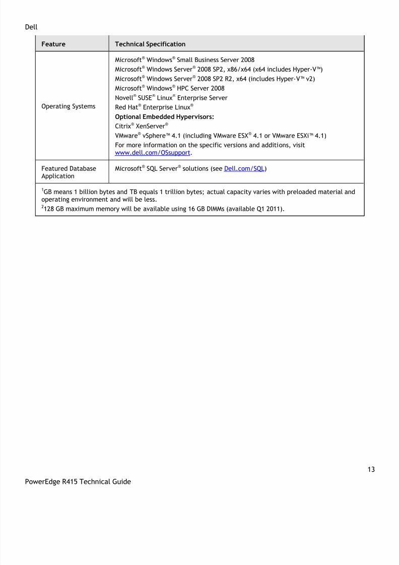
Operating Systems
Microsoft® Windows® Small Business Server 2008
Microsoft® Windows Server® 2008 SP2, x86/x64 (x64 includes Hyper-V™)
Microsoft® Windows Server® 2008 SP2 R2, x64 (includes Hyper-V™ v2)
Microsoft® Windows® HPC Server 2008
Novell®
SUSE®
Linux®
Enterprise ServerRed Hat® Enterprise Linux®
Optional Embedded Hypervisors:
Citrix® XenServer®
VMware® vSphere™ 4.1 (including VMware ESX® 4.1 or VMware ESXi™ 4.1)
For more information on the specific versions and additions, visitwww.dell.com/OSsupport.
Featured DatabaseApplication
Microsoft® SQL Server® solutions (see Dell.com/SQL)
1GB means 1 billion bytes and TB equals 1 trillion bytes; actual capacity varies with preloaded material and
operating environment and will be less.2128 GB maximum memory will be available using 16 GB DIMMs (available Q1 2011).
8/14/2019 r415 Tech Guide 11-18-10_final
http://slidepdf.com/reader/full/r415-tech-guide-11-18-10final 14/63
Dell
14
PowerEdge R415 Technical Guide
3 Mechanical
3.1 Chassis Description
The PowerEdge R415 chassis was designed to deliver a value-based, high-performance server that also offersa level of redundancy. The PowerEdge R415 is available in two chassis configurations:
Cabled hard drive chassis with LED module
Hot-plug hard drive chassis with LCD module
Common features for the two available chassis include the following:
Four 2.5‖ or 3.5‖ SATA or SAS hard drives (cabled or hot-plug)
2.5‖ SSD hard drives
Power supply (non-redundant or redundant)
Dual gigabit LOMs without TOE acceleration
Four DIMM slots supporting each processor
Trusted Platform Module (TPM); in China, the S-TPM (Socket TPM) is used
Riser card for optional PCIe expansion card
Optional iDRAC6 Enterprise and iDRAC6 Express card (mounted on planar without PCI slot occupied)
Support for 11G slim static and slim sliding rails
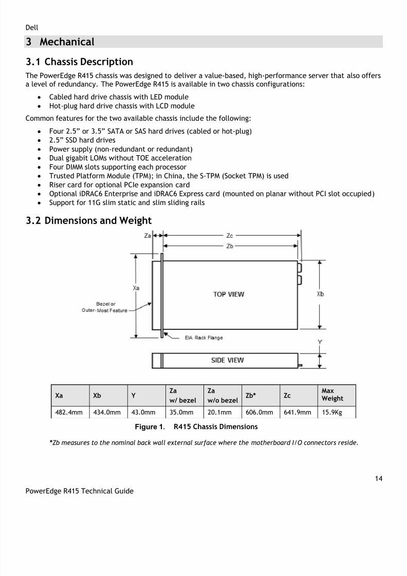
3.2 Dimensions and Weight
Xa Xb YZa
w/ bezel
Za
w/o bezel
Zb* ZcMaxWeight
482.4mm 434.0mm 43.0mm 35.0mm 20.1mm 606.0mm 641.9mm 15.9Kg
Figure 1. R415 Chassis Dimensions
* Zb measures to the nominal back wall external surface where the motherboard I/O connectors reside.

8/14/2019 r415 Tech Guide 11-18-10_final
http://slidepdf.com/reader/full/r415-tech-guide-11-18-10final 15/63
Dell
15
PowerEdge R415 Technical Guide
3.3 Front Panel View and Features
The PowerEdge R415 is available in two chassis configurations: cabled hard drive and hot-plug hard drive.The cabled hard drive chassis includes an LED control panel (Figure 2), and the hot-plug hard drive chassisincludes an LCD control panel (Figure 3). The bezel is optional for both system configurations. See Figure 4.
Figure 2. Front View (Cabled HDD with LED)
Figure 3. Front View (Hot-Plug HDD with LCD)
Figure 4. Front View (With Optional Bezel)
See the Front-Panel Features and Indicators section in the About Your System chapter of the PowerEdgeR415 Hardware Owner’s Manual on Support.Dell.com for more information.
3.4 Back Panel View and Features
The PowerEdge R415 is available with two power-supply configurations: non-redundant and redundant. SeeFigure 5 (non-redundant power supply) and Figure 6 (redundant power supply).
Figure 5. Back View (Non-Redundant Power Supply)

8/14/2019 r415 Tech Guide 11-18-10_final
http://slidepdf.com/reader/full/r415-tech-guide-11-18-10final 16/63
Dell
16
PowerEdge R415 Technical Guide
Figure 6. Back View (Redundant Power Supply)
See the Back-Panel Features and Indicators section in the About Your System chapter of the PowerEdge R415
Hardware Owner’s Manual on Support.Dell.com for more information.
3.5 Power Supply Indicators
The PowerEdge R415 power supplies (redundant and non-redundant) have one status bi-color LED: green forAC power present and amber for a fault.
Table 3. Power Supply Status
LED Power Supply Status
AC Power is not present
AC Power is present
Fault of any kind is detected
DC Power is applied to the system
↔ Redundant power supply mismatch(when hot-plugged/swapped)
See the Power Indicator Codes section in the About Your System chapter of the PowerEdge R415 HardwareOwner’s Manual on Support.Dell.com for more information.
3.6 NIC Indicators
See the NIC Indicator Codes section in the About Your System chapter of the PowerEdge R415 HardwareOwner’s Manual on Support.Dell.com for more information.
3.7 Side Views
Side views of the PowerEdge R415 are shown in Figure 7 and Figure 8.
Figure 7. Left Side View
Figure 8. Right Side View
8/14/2019 r415 Tech Guide 11-18-10_final
http://slidepdf.com/reader/full/r415-tech-guide-11-18-10final 17/63
Dell
17
PowerEdge R415 Technical Guide
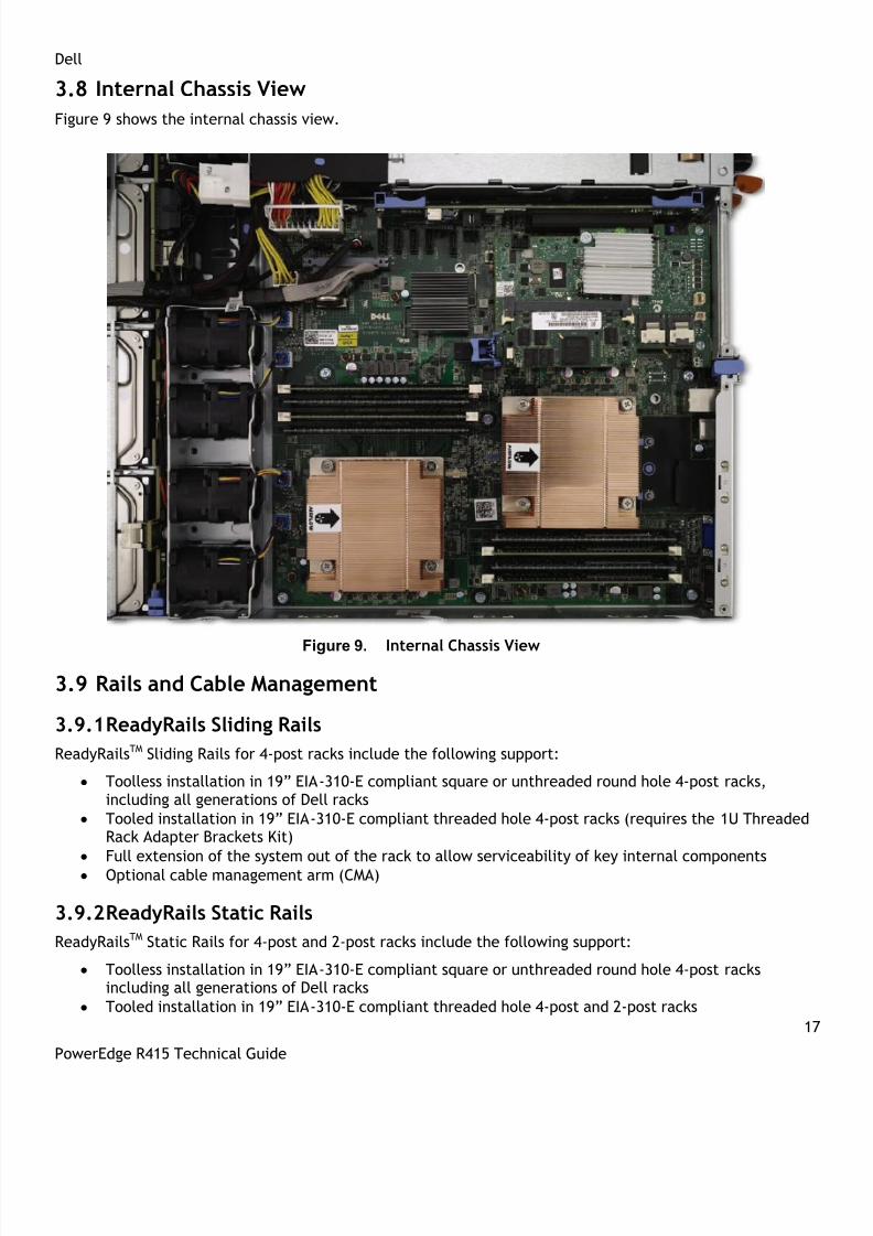
3.8 Internal Chassis View
Figure 9 shows the internal chassis view.
Figure 9. Internal Chassis View
3.9 Rails and Cable Management
3.9.1 ReadyRails Sliding Rails
ReadyRailsTM Sliding Rails for 4-post racks include the following support:
Toolless installation in 19‖ EIA-310-E compliant square or unthreaded round hole 4-post racks,including all generations of Dell racks
Tooled installation in 19‖ EIA-310-E compliant threaded hole 4-post racks (requires the 1U ThreadedRack Adapter Brackets Kit)
Full extension of the system out of the rack to allow serviceability of key internal components
Optional cable management arm (CMA)
3.9.2 ReadyRails Static Rails
ReadyRailsTM Static Rails for 4-post and 2-post racks include the following support:
Toolless installation in 19‖ EIA-310-E compliant square or unthreaded round hole 4-post racksincluding all generations of Dell racks
Tooled installation in 19‖ EIA-310-E compliant threaded hole 4-post and 2-post racks
8/14/2019 r415 Tech Guide 11-18-10_final
http://slidepdf.com/reader/full/r415-tech-guide-11-18-10final 18/63
Dell
18
PowerEdge R415 Technical Guide
For more information on rails, see section 13.2.
3.10 Rack View
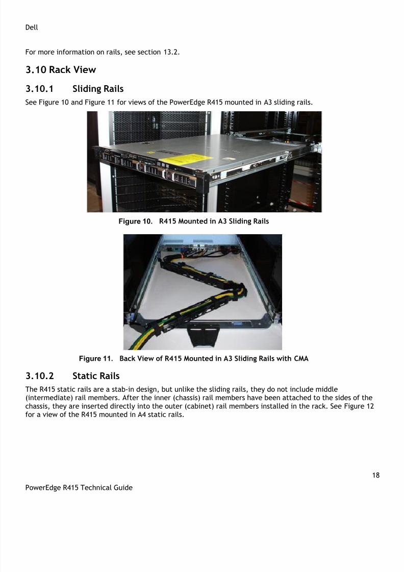
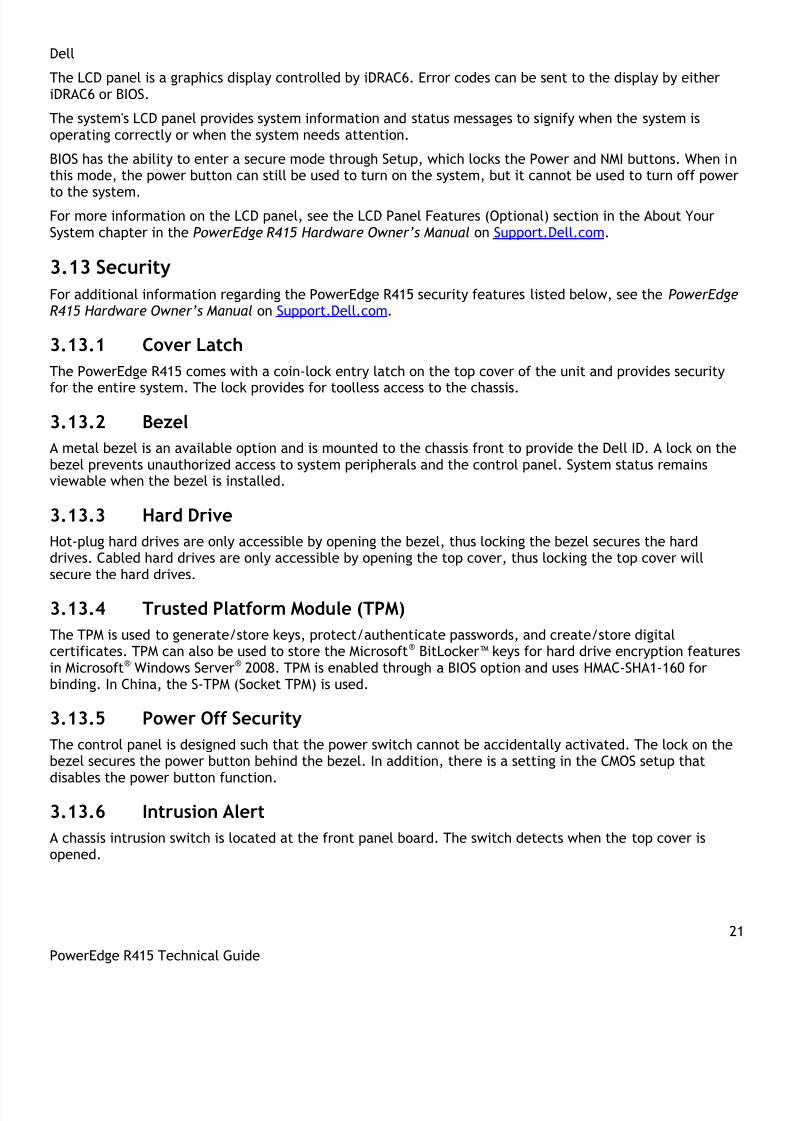
3.10.1 Sliding Rails
See Figure 10 and Figure 11 for views of the PowerEdge R415 mounted in A3 sliding rails.
Figure 10. R415 Mounted in A3 Sliding Rails
Figure 11. Back View of R415 Mounted in A3 Sliding Rails with CMA
3.10.2 Static Rails
The R415 static rails are a stab-in design, but unlike the sliding rails, they do not include middle
(intermediate) rail members. After the inner (chassis) rail members have been attached to the sides of thechassis, they are inserted directly into the outer (cabinet) rail members installed in the rack. See Figure 12for a view of the R415 mounted in A4 static rails.

8/14/2019 r415 Tech Guide 11-18-10_final
http://slidepdf.com/reader/full/r415-tech-guide-11-18-10final 19/63

8/14/2019 r415 Tech Guide 11-18-10_final
http://slidepdf.com/reader/full/r415-tech-guide-11-18-10final 20/63
Dell
20
PowerEdge R415 Technical Guide
3.12.1 LED Panel Configuration
Figure 14 and Figure 15 show the LED panel.
Figure 14. LED panel Configuration
Figure 15. LED Panel (Detailed View)
For a complete description of LED indicators, their causes, and possible courses of action to take to resolve
an error, see the Diagnostic Lights (Optional) section in the About Your System chapter in the PowerEdgeR415 Hardware Owner’s Manual on Support.Dell.com.
3.12.2 LCD Panel Configuration
Figure 16 and Figure 17 show the LCD panel.
Figure 16. LCD Panel Configuration
Figure 17. LCD Panel (Detailed View)
The LCD panel is located on the front of the system chassis to provide user access to buttons, display, andI/O interfaces. Features of the LCD panel include the following:
• ACPI-compliant power button with an integrated green power LED (controlled by iDRAC6)• 128x20 pixel LCD screen with controls• Two navigation buttons• Select button• System ID button• Non-maskable Interrupt (NMI) button (recessed)• Ambient temperature sensor
8/14/2019 r415 Tech Guide 11-18-10_final
http://slidepdf.com/reader/full/r415-tech-guide-11-18-10final 21/63
Dell
21
PowerEdge R415 Technical Guide
The LCD panel is a graphics display controlled by iDRAC6. Error codes can be sent to the display by eitheriDRAC6 or BIOS.
The system's LCD panel provides system information and status messages to signify when the system isoperating correctly or when the system needs attention.
BIOS has the ability to enter a secure mode through Setup, which locks the Power and NMI buttons. When inthis mode, the power button can still be used to turn on the system, but it cannot be used to turn off power
to the system.For more information on the LCD panel, see the LCD Panel Features (Optional) section in the About YourSystem chapter in the PowerEdge R415 Hardware Owner’s Manual on Support.Dell.com.
3.13 Security
For additional information regarding the PowerEdge R415 security features listed below, see the PowerEdgeR415 Hardware Owner’s Manual on Support.Dell.com.
3.13.1 Cover Latch
The PowerEdge R415 comes with a coin-lock entry latch on the top cover of the unit and provides security
for the entire system. The lock provides for toolless access to the chassis.
3.13.2 Bezel
A metal bezel is an available option and is mounted to the chassis front to provide the Dell ID. A lock on thebezel prevents unauthorized access to system peripherals and the control panel. System status remainsviewable when the bezel is installed.
3.13.3 Hard Drive
Hot-plug hard drives are only accessible by opening the bezel, thus locking the bezel secures the harddrives. Cabled hard drives are only accessible by opening the top cover, thus locking the top cover willsecure the hard drives.
3.13.4 Trusted Platform Module (TPM)
The TPM is used to generate/store keys, protect/authenticate passwords, and create/store digitalcertificates. TPM can also be used to store the Microsoft® BitLocker™ keys for hard drive encryption featuresin Microsoft® Windows Server® 2008. TPM is enabled through a BIOS option and uses HMAC-SHA1-160 forbinding. In China, the S-TPM (Socket TPM) is used.
3.13.5 Power Off Security
The control panel is designed such that the power switch cannot be accidentally activated. The lock on thebezel secures the power button behind the bezel. In addition, there is a setting in the CMOS setup thatdisables the power button function.
3.13.6 Intrusion Alert
A chassis intrusion switch is located at the front panel board. The switch detects when the top cover isopened.
8/14/2019 r415 Tech Guide 11-18-10_final
http://slidepdf.com/reader/full/r415-tech-guide-11-18-10final 22/63
Dell
22
PowerEdge R415 Technical Guide
3.13.7 Secure Mode
BIOS can enter a secure boot mode through setup. This mode includes the option to lock out the power andNMI switches on the control panel or to set up a system password.
3.14 USB Key
Dell does not offer USB keys for factory installation. The PowerEdge R415 supports two internal USB
connectors which can be used for USB keys.
3.15 Battery
A replaceable coin-cell CR2032 3V battery is mounted on the planar to provide backup power for the Real-Time Clock and CMOS RAM on the AMD SP5100 chip.
3.16 Field Replaceable Units (FRU)
Parts available for field replacement include:
• Backplane
• CMOS battery• Expansion card
• Front bezel
• Hard drives
• I/O panel
• Memory
• Optical disk drive
• Power distribution board
• Power supply
• Processor
• Processor shroud• System board
• System cover
• System fan
For detailed information on replacing parts for the PowerEdge R415, see the Installing System Componentschapter in the PowerEdge R415 Hardware Owner’s Manual on Support.Dell.com.
3.17 User Accessible Jumpers, Sockets, and Connectors
See the Jumpers and Connectors chapter in the PowerEdge R415 Hardware Owner’s Manual onSupport.Dell.com.

8/14/2019 r415 Tech Guide 11-18-10_final
http://slidepdf.com/reader/full/r415-tech-guide-11-18-10final 23/63
Dell
23
PowerEdge R415 Technical Guide
4 Power, Thermal, Acoustic
4.1 Power Supplies
The PowerEdge R415 is powered by either a non-redundant 480W power supply or an optional redundant500W power supply.
The power supply subsystem provides power to the planar, the four internal hard drive bays, and one slimoptical disk drive bay. Power is soft-switched, allowing power cycling using a switch on the front of thesystem enclosure or through software control (through server management functions). The power system iscompatible with industry standards, such as ACPI and Server 2000.
For a redundant power supply configuration, the second power supply provides hot-pluggable powerredundancy. In redundant mode, the system distributes the power load across both power supplies tomaximize efficiency. When a power supply is removed with the system powered on, the full power load ispicked up by the remaining power supply.
If using only one hot-plug power supply, the power supply is installed in the PS1 location and a blank module(metal cover) is installed in the PS2 location for factory consistency. Electrically, the system can operatewith a single power supply in either bay. The power supply has automatic input voltage detection. Anauxiliary power-out receptacle is not provided on this unit.
The power supply in the chassis has been rated as 82% efficient at 20% and 100% loads, and 85% efficient ata 50% load under 115V AC input line. Redundant power efficiency is 88% at 20% and 100% loads, and 92%efficiency at a 50% load under 230V AC input line.
Field replaceable unit (FRU) data is stored in the memory of the power supply microcontroller. Additionally,the power supply firmware can be updated by the baseboard management controller (BMC) over the PMBus.
4.2 Power Supply Specifications
Table 4 shows the power supply specifications.
Table 4. Power Supply Specifications
Feature Non-Redundant PowerSupply
Redundant Power Supply
DimensionsL-2601 x W-106 x H-40.0 (mm) L-2601 x W-54.5 x H-38.0
(mm)
Status Indicators 1 x bi-color LED 1 x bi-color LED
Integrated Fans None None
Fixed Input Plug
IEC-C14 IEC-C14
AC Cord Rating 15A @ 120VAC,10A @ 240VAC
15A @ 120VAC,10A @ 240VAC
Input Voltage 90–264VAC 90–264VAC
Auto-ranging Yes Yes
Line Frequency 47–63Hz 47–63Hz
Maximum Inrush Current Under typical line conditionsand over the entire system
Under typical line conditionsand over the entire system

8/14/2019 r415 Tech Guide 11-18-10_final
http://slidepdf.com/reader/full/r415-tech-guide-11-18-10final 24/63

8/14/2019 r415 Tech Guide 11-18-10_final
http://slidepdf.com/reader/full/r415-tech-guide-11-18-10final 25/63
Dell
25
PowerEdge R415 Technical Guide
Maximum Shock
Operating Half sine shock in all operational orientations of 31G +/- 5% witha pulse duration of 2.6ms +/-10%
Storage Half sine shock on all six sides of 71G +/- 5% with a pulseduration of 2ms +/-10%
Square wave shock on all six sides of 27G with velocity change @235 in/sec or greater
Altitude
Operating -16 to 3048m (-50 to 10,000ft)
Note: For altitudes above 2950 feet, the maximum operatingtemperature is derated 1°F/550ft.
Storage -16 to 10,600m (-50 to 35,000ft)
The airborne contaminant level is class G2 or lower as defined by ISA-S71.04-1985.
4.5 ENERGY STAR ® ComplianceENERGY STAR qualified configurations can be accessed from the ENERGY STAR Compliance results landingpage on Dell.com.
4.6 Thermal
The thermal design of the PowerEdge R415 includes the following:
Closed loop thermal control algorithm: This method uses feedback temperatures to dynamicallydetermine proper fan speeds.
Comprehensive thermal management: The PowerEdge R415 controls system cooling fan speed basedon several different responses from critical component sensors, such as processor temperature, DIMMtemperature, inlet ambient temperature, and system configurations. The thermal managementadjusts proper cooling ability for the system according to what the system really needs.
Optimized Ventilation: The R415 chassis has a custom ventilation design for optimized air flow path.Each component and peripheral is ensured sufficient air for cooling.
Power-to-Cool: Dell continues to improve the designs and cooling efficiency for server products.
4.7 Acoustics
The acoustical design of the PowerEdge R415 reflects adherence to Dell’s high sound-quality standards.Sound quality is different from sound power level and sound pressure level in that it describes how humansrespond to annoyances in sound, like whistles, hums, etc. One of the sound quality metrics in the Dellspecification is prominence ratio of a tone as shown in Table 7.
Fan speeds and noise levels ramp up during the boot process to add a layer of protection for componentcooling if the system were not to boot properly. Hardware configurations affect system noise levels. Thetable below shows the noise levels of the R415 with different configurations.

8/14/2019 r415 Tech Guide 11-18-10_final
http://slidepdf.com/reader/full/r415-tech-guide-11-18-10final 26/63
8/14/2019 r415 Tech Guide 11-18-10_final
http://slidepdf.com/reader/full/r415-tech-guide-11-18-10final 27/63

8/14/2019 r415 Tech Guide 11-18-10_final
http://slidepdf.com/reader/full/r415-tech-guide-11-18-10final 28/63
Dell
28
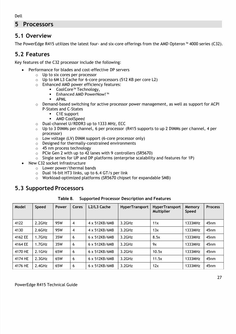
PowerEdge R415 Technical Guide
Model Speed Power Cores L2/L3 Cache HyperTransport HyperTransportMultiplier
MemorySpeed
Process
4180 2.6GHz 95W 6 6 x 512KB/6MB 3.2GHz 13x 1333MHz 45nm
4184 2.8GHz 95W 6 6 x 512KB/6MB 3.2GHz 14x 1333MHz 45nm
5.4 Processor Configurations
The PowerEdge R415 is a two-socket server that will operate with either a single processor or dualprocessors. When the R415 is configured with a single processor, the memory controller is embedded in theprocessor and supports 4 DIMMs (1 GB minimum and a 32 GB maximum). When two processors are installedin the system, it supports a total of 8 DIMMs (2 GB minimum and a 64 GB maximum).
5.5 Processor Installation
See the Processors section in the Installing System Components chapter in the PowerEdge R415 HardwareOwner’s Manual on Support.Dell.com.

8/14/2019 r415 Tech Guide 11-18-10_final
http://slidepdf.com/reader/full/r415-tech-guide-11-18-10final 29/63
Dell
29
PowerEdge R415 Technical Guide
6 Memory
6.1 Overview
The PowerEdge R415 uses DDR3 memory, providing a high-performance, high-speed memory interfacecapable of low-latency response and high throughput.
Key features of the R415 memory system include:
Support for up to 128 GB of memory (8 x 16 GB RDIMMS) (16 GB DIMMS available Q1 2011)
Two channels per processor
Registered ECC DDR3 DIMMs or Unbuffered ECC DDDR3 DIMMs
DDR3 speeds of 1066/1333 MHz
Single rank, dual rank, and quad rank DIMMs
Single bit error correction
Advanced ECC (Chipkill)
Online spare
Parity
Low voltage (LV) DIMM support (6-core processor only)
6.2 DIMMs Supported
The PowerEdge R415 supports DDR3 RDIMMs and UDIMMs. The memory interface uses 1 GB, 2 GB, 4 GB, 8 GB,and 16 GB (available Q1 2011) RDIMMs and 1 GB, 2 GB, and 4 GB UDIMMs. See Table 9.
Table 9. DIMMS Supported
UDIMM RDIMM
1GB, DDR3, 1333MHz, single rank 2GB, DDR3, 1333MHz, single rank
2GB, DDR3, 1333MHz, single rank 4GB, DDR3, 1333MHz, dual rank
4GB, DDR3, 1333MHz, dual rank 8GB, DDR3, 1333MHz, dual rank
1GB, DDR3, 1333MHz, single rank, LV 16GB, DDR3, 1066MHz, quad rank1
2GB, DDR3, 1333MHz, single rank, LV 2GB, DDR3, 1333MHz, single rank, LV
4GB, DDR3, 1333MHz, dual rank, LV 4GB, DDR3, 1333MHz, dual rank, LV
8GB, DDR3, 1333MHz, dual rank, LV1
16GB, DDR3, 1066MHz, quad rank, LV1
1 Available Q1 2011
6.3 DIMM Slots
The DDR3 memory interface consists of two memory channels per processor socket. Each channel supportsup to two RDIMMs for single/dual/quad rank or two UDIMMs. Population order is identified by the silkscreendesignator and the System Information Label (SIL) located on the chassis cover.
The following DIMM population rules apply:
Support for DDR3 1333 MHz UDIMMs or 1066/1333 MHz RDIMMs
2 channels, up to 2 DIMMs per channel
Support for 1333 MHz single and dual-rank DIMMs, 1066 MHz quad-rank DIMMs

8/14/2019 r415 Tech Guide 11-18-10_final
http://slidepdf.com/reader/full/r415-tech-guide-11-18-10final 30/63
Dell
30
PowerEdge R415 Technical Guide
The following is not supported:
Mixing of RDIMMs and UDIMMs
Use of non-ECC UDIMMs
For more information on R415 memory configurations, see the System Memory section in the InstallingSystem Components chapter in the PowerEdge R415 Hardware Owner’s Manual on Support.Dell.com.
6.4 SpeedEach processor has two DDR3 channels capable of supporting speeds up to 1333 MHz. Single- and dual-rankDIMM types can support speeds up to 1333 MHz. Quad-rank DIMMs can support speeds up to 1066 MHz.
If memory modules with different speeds are installed, they will operate at the speed of the slowestinstalled memory module(s).
6.5 Sparing
Memory sparing is supported. Sparing requires a fully-populated memory configuration (8 DIMMs). See Table10 (1 processor) and Table 11 (2 processors).
6.6 MirroringNo mirroring support.
6.7 RAID
No RAID memory support.
6.8 Supported Configurations
Table 10. Supported Configurations (1 Processor)
SystemCapacity
DIMM Slots 1 Socket
Channel A Channel B UDIMM RDIMM
A1 A3 A2 A4 DIMM speed System speed DIMM speed System speed
1GB 1GB — — — 1333 1333 N/A N/A
2GB 1GB — 1GB — 1333 1333 N/A N/A
2GB 2GB — — — 1333 1333 1333 1333
4GB 1GB 1GB 1GB 1GB 1333 1333 N/A N/A
4GB 2GB — 2GB — 1333 1333 1333 1333
8GB 2GB 2GB 2GB 2GB 1333 1333 1333 1333
4GB 4GB — — — 1333 1333 1333 1333
8GB 4GB — 4GB — 1333 1333 1333 1333
16GB 4GB 4GB 4GB 4GB 1333 1066 1333 1066
16GB 8GB — 8GB — N/A N/A 1333 1333
32GB 8GB 8GB 8GB 8GB N/A N/A 1333 1066

8/14/2019 r415 Tech Guide 11-18-10_final
http://slidepdf.com/reader/full/r415-tech-guide-11-18-10final 31/63

8/14/2019 r415 Tech Guide 11-18-10_final
http://slidepdf.com/reader/full/r415-tech-guide-11-18-10final 32/63
Dell
32
PowerEdge R415 Technical Guide
7 Chipset
7.1 Overview
The PowerEdge R415 planar incorporates a dual-IOB configuration using the AMD SR5670 chipset with I/Obridges and the SP5100 Southbridge. The SR5670 is designed to support the AMD C32 processor family,HyperTransport-3 Interface (@ 2.6GHz), DDR3 memory technology, and PCI Express Generation 2. The
chipset consists of the SR5670 and the SP5100.
7.2 AMD I/O Bridges
The PowerEdge R415 I/O board uses the AMD SR5670 I/O Bridges (IOB) to provide links between the C32processor(s) and I/O components. The main components of the I/O controllers are configured to use two x16HyperTransport-3 links (to both processors), up to 42 lanes of PCI Express Gen 2, an x4 PCIe Gen 1Southbridge Interface (SB Link), and an integrated IOAPIC.
7.3 HyperTransport 3 (HT3)
The HyperTransport 3 (HT3) consists of serial point-to-point interconnects for the processors and the I/O
bridges. The PowerEdge R415 has a total of four HT3 links per processor which allows interconnecting eachprocessor with each other and an option for I/O Bridge. Each I/O Bridge has a single x16 HT3 link. A full linkconsists of 16 lanes (full-width) in each direction with a link speed of 6.4 GT/s. The HT3 clocking for CPUHT3 and IOB HT3 are 3.2 GHz and 2.6 GHz, respectively. Therefore, the IOB HT3 link is capable of 5.2 GT/s.For routing, the HT3 links are grouped by x8 Command Address (CAD), x1 Control (CTL), and x1 Clock (CLK)for each RX and TX directions. 7.4 Southbridge Link Interface
The Southbridge (SB) link connects the SR5670 IOB with the AMD Southbridge SP5100. The SB Link (A-LinkExpress) is equivalent to an x4 PCIe Gen 1 link with a transfer rate of 1 GB/s in each direction.
7.5 AMD SP5100 Southbridge (SP5100)SP5100 is a highly-integrated southbridge controller, supporting the following functions:
PCI bus 32-bit interface Rev 2.3 running at 33 MHzo Serial ATA (SATA) ports with transfer rates up to 300 MB/s (R415 supports one SATA port for
optical devices)o Five OHC (full-speed 1.1) and two EHCI (high-speed 2.0) USB host controllers, with up to 12
USB general purpose ports and 2 USB embedded ports (R415 uses 6 ports for internal andexternal use from the general purpose ports)
Power management interface (ACPI 3.0b compliant)
Integrated Micro Controller (IMC) and thermal management
Note: the iDRAC interfaces the Hardware Thermal Control (HTC), not the SP5100
I/O interrupt controller
SMBus 2.0 controller
Low Pin Count (LPC) interface to Super I/O, Trusted Platform Module (TPM), and SPI-VU
Serial Peripheral Interface (SPI) support for up to two devices
4 MB BIOS flash connected to the SP5100 using SPI interface

8/14/2019 r415 Tech Guide 11-18-10_final
http://slidepdf.com/reader/full/r415-tech-guide-11-18-10final 33/63
Dell
33
PowerEdge R415 Technical Guide
8 BIOS
8.1 Overview
The PowerEdge R415 BIOS is based on the Dell BIOS core and supports the following features:
AMD C32 processor support
Simultaneous Multi-Threading (SMT) support
PCI 2.3 compliant
Plug and Play 1.0a compliant
Multiprocessor (MP) 1.4 compliant
Bootable from hard drive, optical drive, iSCSI drive, USB key, and SD card
Power-management support including DBS, power inventory, and multiple power profiles:o Maximum performanceo OS control (DBS)o Active Power Controllero Custom
ACPI 2.0 support (S0, OS-S4, S5 States)
PXE and WOL support for on-board NICs
Memory-sparing support SETUP access through <F2> key at end of POST
USB 2.0 (USB boot code is 1.1 compliant)
F1/F2 error logging in CMOS
Virtual KVM, CD, and floppy support
iDRAC supported
Unified Server Configurator (UEFI 2.1) and UEFI shell support
SMBIOS 2.5
PCI-to-PCI bridge 1.0 compliant
Dell Server Assistant 7.0 support
System Service support
Onboard PCI video BIOS support SATA enabled for CDROM and HDD
PCI FW3.0 compliant
I2O v1.5 ready
Selectable boot support based on BIOS Boot Specification v1.01
El Torito CD-ROM Boot 1.0
Remote BIOS update support
Remote Configuration Interface (RCI) support
Console redirection though COM1
PXE support based on Preboot Execution Environment Specification v2.1
2-byte ID support
ePPID support in flash
Memory remapping support
AC recovery staggering power-up
DIMM mismatch checking
The PowerEdge R415 BIOS does not support the following:
BIOS language localization
BIOS recovery after bad flash

8/14/2019 r415 Tech Guide 11-18-10_final
http://slidepdf.com/reader/full/r415-tech-guide-11-18-10final 34/63
Dell
34
PowerEdge R415 Technical Guide
8.2 Supported ACPI States
The following ACPI states are supported:
ACPI compliance: S0, S4, S5
NO S1, S2, S3 (STR)
State S4 is supported by OS support only.
8.3 Power Management Modes
8.3.1 Dell Active Power Controller
The Dell Active Power Controller (DAPC) is implemented in system BIOS and uses hardware level counters,etc., to determine hardware utilization. The BIOS uses this information to determine when to change theprocessor’s operating frequency. The DAPC is OS independent and means that the OS no longer has control.This provides a consistent power management solution regardless of the installed OS. Some OS(s),particularly hypervisors, do not support power management, thus DAPC provides a solution when thereotherwise would not be one.
8.3.2 Power Saving BIOS Setting (OS Control)With the Power Saving BIOS setting, the OS monitors process/thread level utilization of the processor anduses processor controls to change the processor’s operating frequency. For heavy workloads, the OS will runthe processor at higher frequencies for additional performance. Lighter workloads do not need highperformance, thus the OS will run the processor at lower frequencies.
8.3.3 Maximum Performance
The Maximum Performance mode disables power management. In this mode, the processor frequency isstatically set to the highest supported frequency.
The power management features are implemented via two categories: fixed or generic.
Fixed features use bits defined in the ACPI specification for specific capabilities. The fixed-feature bits givethe OS complete control over the power management of a device, since the location of the bits is given tothe OS in the FACP table. Thus, a driver can directly access bits to control a device’s power management.
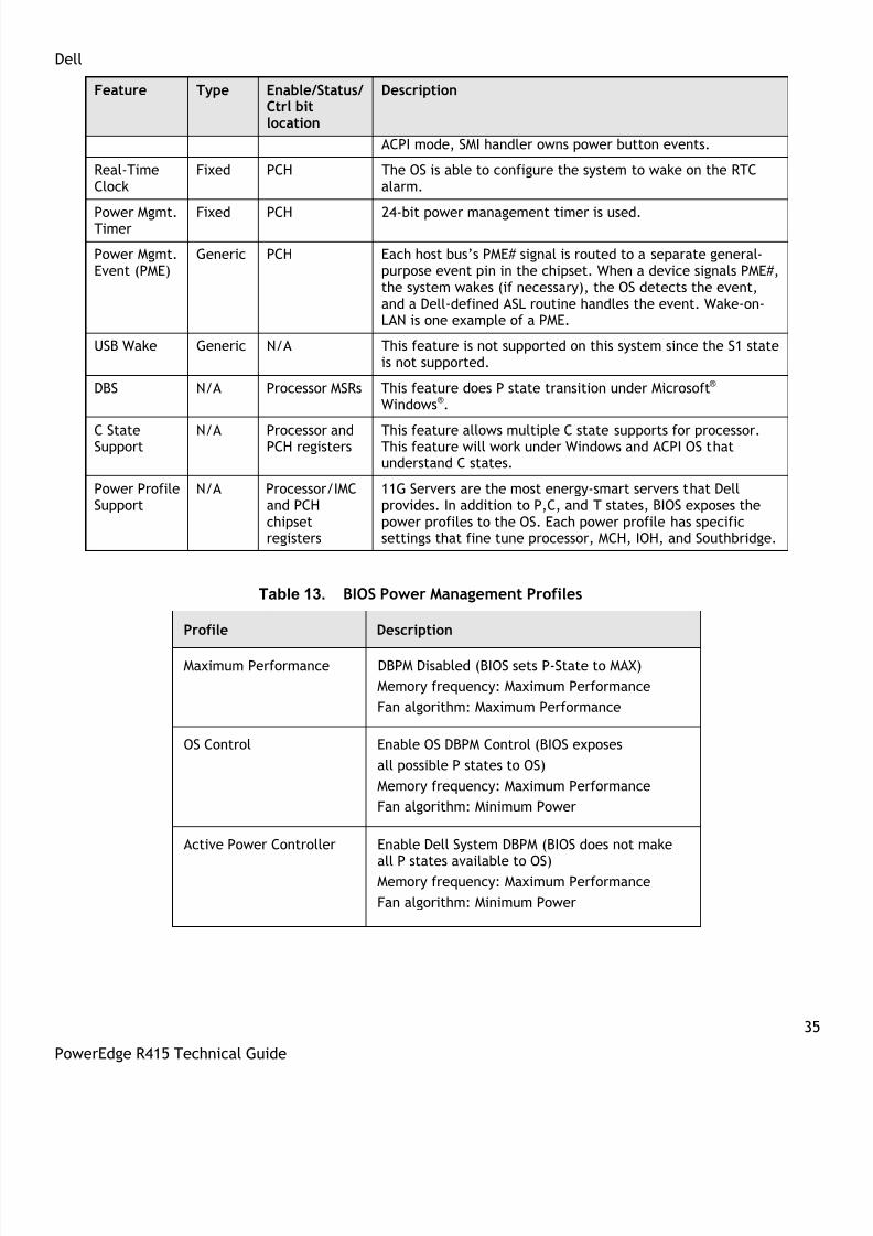
Generic features have defined enable and status bits, but the functionality is not fully visible to the OS. Dellprovides ASL code to handle the details of generic features, allowing the OS to intelligently communicatewith system-specific hardware. Table 12 summarizes power management features, and Table 13 describesthe possible power profiles.
Table 12. BIOS Power Management Features
Feature Type Enable/Status/Ctrl bit
location
Description
ACPI ModeSwitch
Fixed PCH The OS uses the SCI_EN bit to switch from legacy mode toACPI mode.
Sleep States Fixed PCH Supported states: S0 (Working), S4-OS (Hibernation inMicrosoft® Windows® 2000), and S5 (soft-off).
Not supported: S1 (standby or suspend) and S3.
Power Button Fixed PCH In ACPI mode, OS has control of the power button. In non-
8/14/2019 r415 Tech Guide 11-18-10_final
http://slidepdf.com/reader/full/r415-tech-guide-11-18-10final 35/63
Dell
35
PowerEdge R415 Technical Guide
Feature Type Enable/Status/Ctrl bitlocation
Description
ACPI mode, SMI handler owns power button events.
Real-TimeClock
Fixed PCH The OS is able to configure the system to wake on the RTCalarm.
Power Mgmt.Timer Fixed PCH 24-bit power management timer is used.
Power Mgmt.Event (PME)
Generic PCH Each host bus’s PME# signal is routed to a separate general-purpose event pin in the chipset. When a device signals PME#,the system wakes (if necessary), the OS detects the event,and a Dell-defined ASL routine handles the event. Wake-on-LAN is one example of a PME.
USB Wake Generic N/A This feature is not supported on this system since the S1 stateis not supported.
DBS N/A Processor MSRs This feature does P state transition under Microsoft® Windows®.
C StateSupport
N/A Processor andPCH registers
This feature allows multiple C state supports for processor.This feature will work under Windows and ACPI OS thatunderstand C states.
Power ProfileSupport
N/A Processor/IMCand PCHchipsetregisters
11G Servers are the most energy-smart servers that Dellprovides. In addition to P,C, and T states, BIOS exposes thepower profiles to the OS. Each power profile has specificsettings that fine tune processor, MCH, IOH, and Southbridge.
Table 13. BIOS Power Management Profiles
Profile Description
Maximum Performance DBPM Disabled (BIOS sets P-State to MAX)
Memory frequency: Maximum Performance
Fan algorithm: Maximum Performance
OS Control Enable OS DBPM Control (BIOS exposes
all possible P states to OS)
Memory frequency: Maximum Performance
Fan algorithm: Minimum Power
Active Power Controller Enable Dell System DBPM (BIOS does not make
all P states available to OS)Memory frequency: Maximum Performance
Fan algorithm: Minimum Power

8/14/2019 r415 Tech Guide 11-18-10_final
http://slidepdf.com/reader/full/r415-tech-guide-11-18-10final 36/63
Dell
36
PowerEdge R415 Technical Guide
Profile Description
Maximum Performance DBPM Disabled (BIOS sets P-State to MAX)
Memory frequency: Maximum Performance
Fan algorithm: Maximum Performance
Custom CPU Power and Performance Management:Maximum Performance, Minimum Power, OSDBPM, System DBPM
Memory Power and Performance Management:Maximum Performance, 1333MHz, 1067MHz,800MHz, Minimum Power
Fan Algorithm: Maximum Performance, MinimumPower

8/14/2019 r415 Tech Guide 11-18-10_final
http://slidepdf.com/reader/full/r415-tech-guide-11-18-10final 37/63
Dell
37
PowerEdge R415 Technical Guide
9 Embedded NICs/LAN on Motherboard (LOM)
The Broadcom® 5716 LOM chip is located on the PowerEdge R415 motherboard. The 5716 chip is connectedto the IOH via a PCI Express x4 gen2 link. The chip provides two 1xGB Ethernet ports with two RJ-45connectors on the back of the system. The firmware for the LOM chip resides in a flash part. The PowerEdgeR415 supports Wake-On-LAN (WOL) from either port.
8/14/2019 r415 Tech Guide 11-18-10_final
http://slidepdf.com/reader/full/r415-tech-guide-11-18-10final 38/63
Dell
38
PowerEdge R415 Technical Guide
10 I/O Slots
10.1 Overview
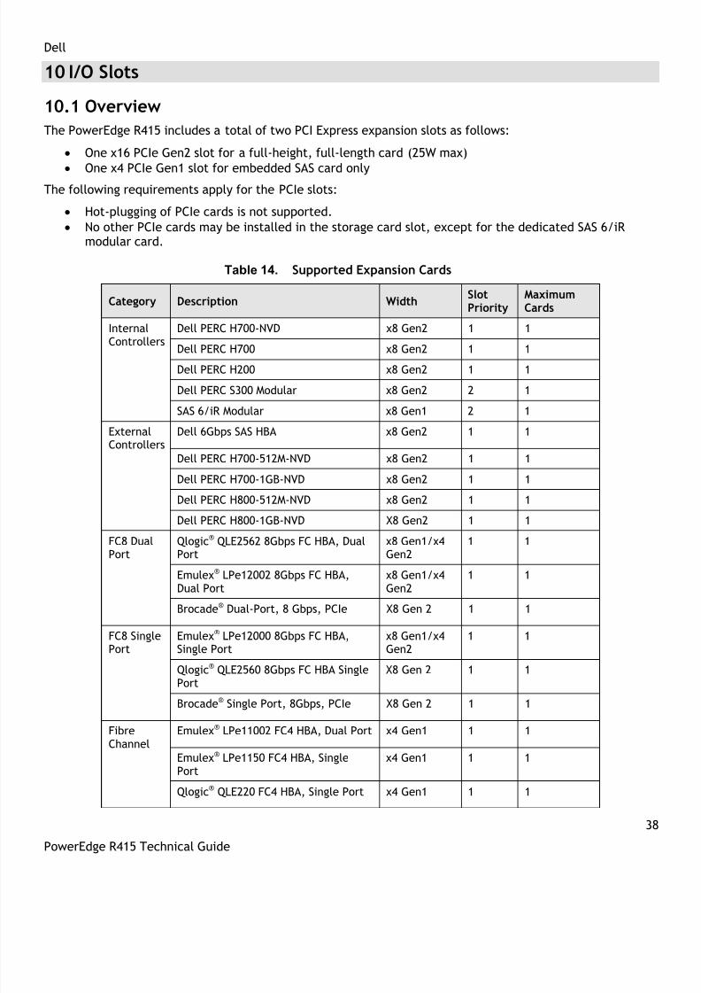
The PowerEdge R415 includes a total of two PCI Express expansion slots as follows:
One x16 PCIe Gen2 slot for a full-height, full-length card (25W max)
One x4 PCIe Gen1 slot for embedded SAS card only
The following requirements apply for the PCIe slots:
Hot-plugging of PCIe cards is not supported.
No other PCIe cards may be installed in the storage card slot, except for the dedicated SAS 6/iRmodular card.
Table 14. Supported Expansion Cards
Category Description WidthSlotPriority
MaximumCards
InternalControllers
Dell PERC H700-NVD x8 Gen2 1 1
Dell PERC H700 x8 Gen2 1 1
Dell PERC H200 x8 Gen2 1 1
Dell PERC S300 Modular x8 Gen2 2 1
SAS 6/iR Modular x8 Gen1 2 1
ExternalControllers
Dell 6Gbps SAS HBA x8 Gen2 1 1
Dell PERC H700-512M-NVD x8 Gen2 1 1
Dell PERC H700-1GB-NVD x8 Gen2 1 1
Dell PERC H800-512M-NVD x8 Gen2 1 1
Dell PERC H800-1GB-NVD X8 Gen2 1 1
FC8 DualPort
Qlogic® QLE2562 8Gbps FC HBA, DualPort
x8 Gen1/x4Gen2
1 1
Emulex® LPe12002 8Gbps FC HBA,Dual Port
x8 Gen1/x4Gen2
1 1
Brocade® Dual-Port, 8 Gbps, PCIe X8 Gen 2 1 1
FC8 SinglePort
Emulex® LPe12000 8Gbps FC HBA,Single Port
x8 Gen1/x4Gen2
1 1
Qlogic® QLE2560 8Gbps FC HBA SinglePort
X8 Gen 2 1 1
Brocade® Single Port, 8Gbps, PCIe X8 Gen 2 1 1
FibreChannel
Emulex® LPe11002 FC4 HBA, Dual Port x4 Gen1 1 1
Emulex® LPe1150 FC4 HBA, SinglePort
x4 Gen1 1 1
Qlogic® QLE220 FC4 HBA, Single Port x4 Gen1 1 1

8/14/2019 r415 Tech Guide 11-18-10_final
http://slidepdf.com/reader/full/r415-tech-guide-11-18-10final 39/63
Dell
39
PowerEdge R415 Technical Guide
Category Description WidthSlotPriority
MaximumCards
Qlogic® QLE2460 FC4 HBA, Single Port x4 Gen1 1 1
Qlogic® QLE2462 FC4 HBA, Dual Port x4 Gen1 1 1
Qlogic® QLE8152 8Gbps FC HBA, Dual
Port
x8 Gen1/x4
Gen2
1 1
CNA Qlogic® Dual Port 10GbE FCoE, SFP+ X8 Gen 2 1 1
Emulex® Dual Port 10GbE, iSCSI, HBA,SFP+
X8 Gen 2 1 1
10GbEthernetControllers
1020 Brocade® Dual Port 10G FCoE,SFP+, PCIe
X8 Gen 2 1 1
Broadcom® 57712 Dual Port 10 GBase-T, PCIe
X8 Gen2 1 1
Broadcom® NetXtreme™ II 57711 Dual-Port SFP+/Direct Attach 10GbE PCIe
with TOE and iSCSI Offload
X8 Gen 2 1 1
Intel® Dual Port 10GE Base-T, PCIeGen 2, Sr-IOV, FCoE
X8 Gen 2 1 1
Intel® Ethernet X520 DA2 Dual-Port10Gb Server Adapter
X8 Gen 2 1 1
Intel® X520-T2 Dual-Port 10GbE ServerAdapter
X8 Gen 2 1 1
Emulex® OCE10102FXD, 10G PCIeFCoE CAN, Dual Port
X8 Gen 2 1 1
1G NICs Intel® PCIe Quad Port Copper x4
Gen1/Gen2
1 1
Intel® PRO/1000PT 1G Cu Single PortNIC
x1 Gen1 1 1
Broadcom® 5709 IPv6 1G Cu Dual PortNIC TOE
x4 Gen1 1 1
Broadcom® 5709 IPV6 1G CU Dual PortNIC TOE/iSOE
x4 Gen1 1 1
Intel® PCIe Dual Port Copper x4Gen1/Gen2
1 1
Broadcom® 5709 Quad Port, LP & FHbracket, ToE, iSoE
X4 Gen2 1 1
For more information on PCIe cards, see Expansion Cards and Expansion-Card Risers in the Installing SystemComponents chapter in the PowerEdge R415 Hardware Owner’s Manual on Support.Dell.com.
8/14/2019 r415 Tech Guide 11-18-10_final
http://slidepdf.com/reader/full/r415-tech-guide-11-18-10final 40/63
Dell
40
PowerEdge R415 Technical Guide
10.2 Boot Order
The boot order can be customized based on bootable devices detected by the BIOS.
10.3 NICs
See details in the table above.
10.4 NIC and LOM Enumeration
LOMs will enumerate first in order to have consistent Ethernet assignment (i.e., eth0). NIC enumerationvaries depending on configuration.
10.5 PCI Card Dimensions
For information about PCI slots and card dimensions, see the Back-Panel Features and Indicators section inthe About Your System chapter in the PowerEdge R415 Hardware Owner ’s Manual on Support.Dell.com.

8/14/2019 r415 Tech Guide 11-18-10_final
http://slidepdf.com/reader/full/r415-tech-guide-11-18-10final 41/63
Dell
41
PowerEdge R415 Technical Guide
11 Storage
11.1 Overview
The PowerEdge R415 supports up to four hard drives in one of the following configurations:
4 x 3.5‖ cabled SATA from motherboard SATA connector
4 x 3.5‖ cabled SAS or SATA with add-on storage controller
4 x 3.5‖ hot-swap SAS or SATA with add-on storage controller
4 x 2.5‖ hot-swap SAS or SATA or SSD with add-on storage controller
The 2.5‖ hard drive requires a hot-plug configuration with the 3.5‖ hard drive carrier and retention kit.After a chassis configuration is chosen (cabled or hot-plug) there is not an available upgrade option. SeeTable 15.
Table 15. Supported Hard Drives
Form Factor Capacity Speed Type Cabled or Hot-plug
3.5‖ 160GB, 250GB, 500GB, 1TB, 2TB 7.2K SATA Both
3.5‖ 500GB, 1TB, 2TB 7.2K NL SAS 1TB: cabled only3.5‖ 146GB 15K SAS 3GB Both
3.5‖ 300GB, 450GB, 600GB 15K SAS 6GB Both
2.5‖ 146GB, 300GB, 600GB 10K SAS All: hot-plug only (with HDDcarrier)
2.5‖ 50GB N/A SSD Both
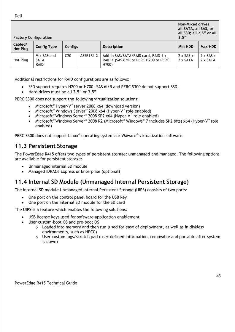
11.2 RAID Configurations
Table 16 details RAID configurations for the PowerEdge R415.
Table 16. RAID Configurations
Factory Configuration
Non-Mixed drivesall SATA, all SAS, orall SSD; all 2.5” or all3.5”
Cabled/Hot Plug
Config Type Configs Description Min HDD Max HDD
CabledEmbeddedSATA
C1 MSTCBL On-board SATA controller (AMD SR5670) 1 4
Cabled SAS/SATANo RAID
C2 ASSCBL Add-in SAS/SATA RAID card, no RAID (SAS6/iR or PERC H200)
1 4
Cabled
SAS/SATARAID
C3 ASSR0CBL Add-in SAS/SATA RAID card, RAID 0 (SAS6/iR or PERC H200 or PERC H700
1 4
C4 ASSR1CBL Add-in SAS/SATA RAID card, RAID 1 (SAS6/iR or PERC H200 or PERC H700)
2 2

8/14/2019 r415 Tech Guide 11-18-10_final
http://slidepdf.com/reader/full/r415-tech-guide-11-18-10final 42/63
Dell
42
PowerEdge R415 Technical Guide
Factory Configuration
Non-Mixed drivesall SATA, all SAS, orall SSD; all 2.5” or all3.5”
Cabled/Hot Plug
Config Type Configs Description Min HDD Max HDD
C5 ASSR5CBL Add-in SAS/SATA RAID card, RAID 5 (PERCH700)
3 4
C6 ASSR6CBL Add-in SAS/SATA RAID card, RAID 6 (PERCH700)
4 4
C7 ASSR10CBL
Add-in SAS/SATA RAID card, RAID 10(PERC H200 or H700)
4 4
C8 ASSR5CBL Add-in SAS/SATA RAID card, RAID 5 (PERCS300)
3 4
C9 ASSR10CBL
Add-in SAS/SATA RAID card, RAID 10(PERC S300)
4 4
Cabled/
Hot Plug Config Type Configs Description Min HDD Max HDD
Hot PlugSAS/SATA/SSDNo RAID
C10 ASS Add-in SAS/SATA RAID card, No RAID (SAS6/iR or PERC H200)
1 4
Hot PlugSAS/SATA/SSDRAID
C11 ASSR0 Add-in SAS/SATA RAID card, RAID 0 (SAS6/iR or PERC H200 or PERC H700)
1 4
C12 ASSR1 Add-in SAS/SATA RAID card, RAID 1 (SAS6/iR or PERC H200 or PERC H700)
2 2
C13 ASSR5 Add-in SAS/SATA RAID card, RAID 5 (PERCH700)
3 4
C14 ASSR6 Add-in SAS/SATA RAID card, RAID 6 (PERC
H700)
4 4
C15 ASSR10 Add-in SAS/SATA RAID card, RAID 10(PERC H200 or H700)
4 4
Hot PlugSAS/SATARAID
C16 ASSR5 Add-in SAS/SATA RAID card, RAID 5 (PERCS300)
3 4
C17 ASSR10 Add-in SAS/SATA RAID card, RAID 10(PERC S300)
4 4
Hot PlugSAS/SATA/SSDRAID 1 + RAID1
C18 ASSR1R1 Add-in SAS/SATA/RAID card, RAID 1 +RAID 1 (SAS 6/iR or PERC H200 or PERCH700)
2+2 2+2
Mixed HDD (SAS + SATA) Factory Configuration
Mixed SAS + SATAMin: 2xSAS+1xSATAMax: 2xSAS+2xSATA;all 2.5” or 3.5”
Hot PlugMix SAS andSATANo RAID
C19 ASS-X Add-in SAS/SATA RAID card, no RAID (SAS6/iR or PERC H200)
2 x SAS +1 x SATA
2 x SAS +1 x SATA
8/14/2019 r415 Tech Guide 11-18-10_final
http://slidepdf.com/reader/full/r415-tech-guide-11-18-10final 43/63

8/14/2019 r415 Tech Guide 11-18-10_final
http://slidepdf.com/reader/full/r415-tech-guide-11-18-10final 44/63

8/14/2019 r415 Tech Guide 11-18-10_final
http://slidepdf.com/reader/full/r415-tech-guide-11-18-10final 45/63

8/14/2019 r415 Tech Guide 11-18-10_final
http://slidepdf.com/reader/full/r415-tech-guide-11-18-10final 46/63

8/14/2019 r415 Tech Guide 11-18-10_final
http://slidepdf.com/reader/full/r415-tech-guide-11-18-10final 47/63

8/14/2019 r415 Tech Guide 11-18-10_final
http://slidepdf.com/reader/full/r415-tech-guide-11-18-10final 48/63
Dell
48
PowerEdge R415 Technical Guide
Figure 20. R415 Static Rails
One key factor in selecting the proper rails is identifying the type of rack in which they will be installed.Both the sliding rails and the static rails support mounting in 19‖-wide, EIA-310-E compliant 4-post racks,but only the static rails support mounting in 2-post (Telco) racks.
Table 18 provides a summary of the rack types supported by the R415 rails.
Table 18. Supported Racks
ProductRailID
MountingInterface
RailType
Rack Types Supported
4-Post 2-Post
Square Round Thread Flush Center
R415A3 ReadyRails Sliding √ √ √
* X X
A4 ReadyRails/Generic Static √ √ √ √ √ *Requires the 1U Threaded Rack Adapter Brackets Kit (Dell PN 8Y19G)
Screws are not included in the static rail kit since the threaded racks are offered with a variety of threaddesignations. Users must provide their own screws when mounting the static rails in threaded or 2-postracks.
Other factors to consider in rail selection include the spacing between the front and rear mounting flangesof the rack, the type and location of any equipment mounted in the back of the rack such as powerdistribution units (PDUs), and the overall depth of the rack. See Table 19.
Due to their reduced complexity and lack of need for CMA support, the static rails offer a greateradjustability range and an overall smaller footprint than the sliding rails.

8/14/2019 r415 Tech Guide 11-18-10_final
http://slidepdf.com/reader/full/r415-tech-guide-11-18-10final 49/63
Dell
49
PowerEdge R415 Technical Guide
Table 19. Rail Adjustability Ranges and Depth
ProductRailID
MountingInterface
RailType
Rail Adjustability Range (mm) Rail Depth (mm)
Square Round Threaded withoutCMA
withCMAMin Max Min Max Min Max
R415
A3 ReadyRails Sliding 686 883 672 876 651 897 714 835
A4ReadyRails/Generic
Static 608 879 594 872 604 890 622 N/A
The adjustment range of the rails is a function of the type of rack in which they are being mounted. Themin-max values listed above represent the allowable distance between the front and rear mounting flangesin the rack. Rail depth represents the minimum depth of the rail as measured from the rack front mountingflanges when the rail rear bracket is positioned all the way forward.
13.3 Cable Management Arm (CMA)
The optional cable management arm (CMA) for the R415 organizes and secures the cords and cables exiting
the back of the server and unfolds to allow the server to extend out of the rack without having to detachthe cables. Some key features of the R415 CMA include:
Large U-shaped baskets support dense cable loads.
An open-vent pattern allows optimal airflow.
The CMA mounting is fully-reversible (can be mounted on either side) with no conversion required.
Hook-and-loop straps are used (rather than plastic tie wraps) to eliminate the risk of cable damageduring cycling.
A low-profile fixed tray is included to support and retain the CMA in its fully-closed position. The CMA and the tray can be mounted without the use of tools using simple and intuitive snap-in
designs.

8/14/2019 r415 Tech Guide 11-18-10_final
http://slidepdf.com/reader/full/r415-tech-guide-11-18-10final 50/63
Dell
50
PowerEdge R415 Technical Guide
14 Operating Systems and Virtualization
For detailed information, see the following:
• Operating System Support Matrix for Dell PowerEdge Systems on www.Dell.com• Dell PowerEdge R415 Systems Getting Started With Your System guide on Support.Dell.com

8/14/2019 r415 Tech Guide 11-18-10_final
http://slidepdf.com/reader/full/r415-tech-guide-11-18-10final 51/63
Dell
51
PowerEdge R415 Technical Guide
15 Systems Management
15.1 Overview/Description
Dell aims on delivering open, flexible, and integrated solutions that help you reduce the complexity ofmanaging disparate IT assets by building comprehensive IT management solutions. Combining DellPowerEdge Servers with a wide selection of Dell-developed management solutions gives you choice and
flexibility, so you can simplify and save in environments of any size. To help you meet your serverperformance demands, Dell offers Dell OpenManage™ systems management solutions for:
• Deployment of one or many servers from a single console
• Monitoring of server and storage health and maintenance
• Update of system, operating system, and application software
Dell offers IT management solutions for organizations of all sizes—priced, sized, and supported right.
15.2 Server Management
A Dell Systems Management and Documentation DVD and a Dell Management Console DVD are included withthe product. ISO images are also available. A brief description of available content:
• Dell Systems Build and Update Utility: Dell Systems Build and Update Utility assists in OS install andpre-OS hardware configuration and updates.
• OpenManage Server Administrator: The OpenManage Server Administrator (OMSA) tool provides acomprehensive, one-to-one systems management solution, designed for system administrators tomanage systems locally and remotely on a network. OMSA allows system administrators to focus onmanaging their entire network by providing comprehensive one-to-one systems management.
• Management Console: Our legacy IT Assistant console is also included, as well as tools to allow accessto our remote management products. These tools are Remote Access Service, for iDRAC, and the BMCManagement Utility.
• Active Directory Snap-in Utility: The Active Directory Snap-in Utility provides an extension snap-in to
the Microsoft Active Directory. This allows you to manage Dell specific Active Directory objects. TheDell-specific schema class definitions and their installation are also included on the DVD.
• Dell Systems Service Diagnostics Tools: Dell Systems Service and Diagnostics tools deliver the latestDell optimized drivers, utilities, and operating system-based diagnostics that you can use to updateyour system.
• eDocs: The section includes PDF files for PowerEdge systems, storage peripheral, and OpenManagesoftware.
• Dell Management Console DVD: The Dell Management Console is a Web-based systems managementsoftware that enables you to discover and inventory devices on your network. It also providesadvanced functions, such as health and performance monitoring of networked devices and patchmanagement capabilities for Dell systems.
• Server Update Utility: In addition to the Systems Management Tools and Documentation and DellManagement Console DVDs, customers have the option to obtain Server Update Utility DVD. This DVDhas an inventory tool for managing updates to firmware, BIOS and drivers for either Linux or Windowsvarieties.
15.3 Embedded Server Management
The PowerEdge R415 implements circuitry for the next generation of Embedded Server Management. It isIntelligent Platform Management Interface (IPMI) v2.0 compliant. The optional iDRAC (Integrated Dell

8/14/2019 r415 Tech Guide 11-18-10_final
http://slidepdf.com/reader/full/r415-tech-guide-11-18-10final 52/63
Dell
52
PowerEdge R415 Technical Guide
Remote Access Controller) is responsible for acting as an interface between the host system and itsmanagement software and the periphery devices. These periphery devices consist of the PSUs, the storagebackplane, integrated SAS HBA or PERC 6/I, and control panel with display.
The optional upgrade to iDRAC6 provides features for managing the server remotely or in data center lights-out environments.
Advanced iDRAC features require the installation of the optional iDRAC6 Enterprise card.
15.4 Lifecycle Controller and Unified Server Configurator
Embedded management is comprised of several interdependent pieces:
• Lifecycle Controller
• Unified Server Configurator
• iDRAC6
• vFlash
Lifecycle controller powers the embedded management features. It is integrated and tamperproof storagefor system-management tools and enablement utilities (firmware, drivers, etc.). It is flash partitioned tosupport multiple, future-use cases.
Dell Unified Server Configurator (USC) is a local 1:1 graphical user interface embedded on LifecycleController that aids in local server provisioning in a pre-OS environment. For servers with iDRAC Express, theLifecycle Controller offers OS install, platform updates, platform configuration, and diagnostics capabilities.For servers without iDRAC Express, this utility has limited functionality and offers OS install and diagnosticscapabilities only.
To access the Unified Server Configurator, press the <F10> key within 10 seconds of the Dell logo’sappearance during the system boot process. Current functionality enabled by the Unified ServerConfigurator includes:
Table 20. Unified Server Configurator Features and Description
Feature DescriptionFaster O/S Installation Drivers and the installation utility are embedded on
system, so no need to scour DELL.COM
Faster System Updates Integration with Dell support automatically directedto latest versions of the Unified Server Configurator,iDRAC, RAID, BIOS, NIC, and Power Supply
Update Rollback Ability to recover to previous ―known good state‖ forall updatable components
More Comprehensive Diagnostics Diagnostic utilities are embedded on system
Simplified Hardware Configuration Detects RAID controller and allows user to configurevirtual disk and choose virtual disk as boot device,eliminating the need to launch a separate utility. Alsoprovides configuration for iDRAC, BIOS, and NIC/LOM.
15.5 iDRAC Express
The optional iDRAC Express is the first tier of iDRAC6 upgrades. In addition to upgrading the system with aLifecycle Controller, the iDRAC6 Express offers the following key features:
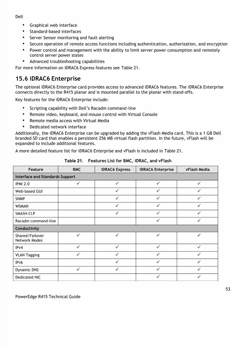
8/14/2019 r415 Tech Guide 11-18-10_final
http://slidepdf.com/reader/full/r415-tech-guide-11-18-10final 53/63
Dell
53
PowerEdge R415 Technical Guide
• Graphical web interface
• Standard-based interfaces
• Server Sensor monitoring and fault alerting
• Secure operation of remote access functions including authentication, authorization, and encryption
• Power control and management with the ability to limit server power consumption and remotelycontrol server power states
• Advanced troubleshooting capabilitiesFor more information on iDRAC6 Express features see Table 21.
15.6 iDRAC6 Enterprise
The optional iDRAC6 Enterprise card provides access to advanced iDRAC6 features. The iDRAC6 Enterpriseconnects directly to the R415 planar and is mounted parallel to the planar with stand-offs.
Key features for the iDRAC6 Enterprise include:
• Scripting capability with Dell’s Racadm command-line
• Remote video, keyboard, and mouse control with Virtual Console
• Remote media access with Virtual Media• Dedicated network interface
Additionally, the iDRAC6 Enterprise can be upgraded by adding the vFlash Media card. This is a 1 GB Dellbranded SD card that enables a persistent 256 MB virtual flash partition. In the future, vFlash will beexpanded to include additional features.
A more detailed feature list for iDRAC6 Enterprise and vFlash is included in Table 21.
Table 21. Features List for BMC, iDRAC, and vFlash
Feature BMC iDRAC6 Express iDRAC6 Enterprise vFlash Media
Interface and Standards Support
IPMI 2.0
Web-based GUI
SNMP
WSMAN
SMASH-CLP
Racadm command-line
Conductivity
Shared/FailoverNetwork Modes
IPv4
VLAN Tagging
IPv6
Dynamic DNS
Dedicated NIC

8/14/2019 r415 Tech Guide 11-18-10_final
http://slidepdf.com/reader/full/r415-tech-guide-11-18-10final 54/63
Dell
54
PowerEdge R415 Technical Guide
Feature BMC iDRAC6 Express iDRAC6 Enterprise vFlash Media
Security and Authentication
Role-based Authority
Local Users
Active Directory
SSL Encryption
Remote Management and Remediation
Remote FirmwareUpdate
Server power control
Serial-over-LAN (withproxy)
Serial-over-LAN (noproxy)
Power cappingLast crash screencapture
Boot capture
Serial-over-LAN
Virtual media
Virtual console
Virtual console sharing
Virtual flash
Monitoring
Sensor Monitoring andAlerting
Real-time PowerMonitoring*
Real-time PowerGraphing*
Historical PowerCounters*
Logging Features
System Event Log
RAC Log
Trace Log

8/14/2019 r415 Tech Guide 11-18-10_final
http://slidepdf.com/reader/full/r415-tech-guide-11-18-10final 55/63
Dell
55
PowerEdge R415 Technical Guide
16 USB Peripherals
The PowerEdge R415 supports the following USB devices:
USB key (bootable)
Keyboard (only one USB keyboard is supported)
Mouse (only one USB mouse is supported)
Optional USB DVD-ROM

8/14/2019 r415 Tech Guide 11-18-10_final
http://slidepdf.com/reader/full/r415-tech-guide-11-18-10final 56/63
Dell
56
PowerEdge R415 Technical Guide
Appendix A. Statement of Volatility
The Dell PowerEdge R415 contains both volatile and non-volatile (NV) components. Volatile components losetheir data immediately upon removal of power from the component. Non-volatile components continue toretain their data even after the power has been removed from the component. Components chosen as user-definable configuration options (those not soldered to the motherboard) are not included in the Statement
of Volatility. Configuration option information (pertinent to options such as microprocessors, systemmemory, remote access controllers, and storage controllers) is available by component separately. The NVcomponents detailed in Table 22 are present in the PowerEdge R415 server.
Table 22. R415 Volatility Table
Server BIOS Memory Details
Size: 32Mbit
Type [e.g., Flash PROM, EEPROM]: Flash EEPROM
Can user programs or operating system writedata to it during normal operation?
No
Purpose? [e.g., boot code] Boot Code and Configuration Information
How is data input to this memory? Loading flash memory requires a vendorprovided firmware file and loader programwhich is executed by booting up the systemfrom a floppy or OS based executable containingthe firmware file and the loader. System loadedwith arbitrary data in firmware memory wouldnot operate.
How is this memory write protected? Software write protected
Server CMOS (Complementary Metal-OxideSemiconductor) Memory
Details
Size: 512 bytes
Type: [e.g., Flash PROM, EEPROM]: Battery backed NVRAM
Can user programs or operating system writedata to it during normal operation?
No
Purpose? [e.g., boot code] RTC and configuration settings
How is data input to this memory? F2 Setup Menu during POST
How is this memory write protected? N/A
Remarks Jumper on motherboard can be used to clear to
factory default settings

8/14/2019 r415 Tech Guide 11-18-10_final
http://slidepdf.com/reader/full/r415-tech-guide-11-18-10final 57/63
Dell
57
PowerEdge R415 Technical Guide
LOM (LAN [Network Interface] onMotherboard) Memory
Details
Size: 4Mb (1MB)
Type: [e.g., Flash PROM, EEPROM]: Flash
Can user programs or operating system write
data to it during normal operation?
Yes, under software control
Purpose? [e.g., boot code] Contains LOM boot code and config data
How is data input to this memory? Requires vendor provided firmware file andloader program used during factory assembly orpossible field update. A system loaded witharbitrary data in firmware memory would notoperate.
How is this memory write protected? Software control
Server System FRU Details
Size: 4KB
Type: [e.g., Flash PROM, EEPROM]: SEEPROM
Can user programs or operating system writedata to it during normal operation?
No
Purpose? [e.g., boot code] Store System FRU
How is data input to this memory? BMC controller write
How is this memory write protected? Not write protected
Power Supply FRU Details
Size: 256 bytes
Type: [e.g., Flash PROM, EEPROM]: SEEPROM
Can user programs or operating system writedata to it during normal operation?
No
Purpose? [e.g., boot code] Store power supply information
How is data input to this memory? Programmed by the power supplymanufacturer.
How is this memory write protected? Not write protected

8/14/2019 r415 Tech Guide 11-18-10_final
http://slidepdf.com/reader/full/r415-tech-guide-11-18-10final 58/63

8/14/2019 r415 Tech Guide 11-18-10_final
http://slidepdf.com/reader/full/r415-tech-guide-11-18-10final 59/63
Dell
59
PowerEdge R415 Technical Guide
Server BMC (Baseboard ManagementController) Firmware Flash Memory
Details
Size: 16MB Flash
Type: [e.g., Flash PROM, EEPROM]: SPI Flash
Can user programs or operating system writedata to it during normal operation?
No
Purpose? [e.g., boot code] Stores the BMC Firmware
How is data input to this memory? Loading flash memory requires a vendorprovided firmware file and loader programwhich is executed by booting up the systemfrom a floppy or OS based executablecontaining the firmware file and the loader.System loaded with arbitrary data in firmwarememory would not operate.
How is this memory write protected? Software write protected
To obtain optional component information, please refer to the Dell Statement of Volatility for the individualcomponents. Please direct any questions to your Dell Marketing contact.

8/14/2019 r415 Tech Guide 11-18-10_final
http://slidepdf.com/reader/full/r415-tech-guide-11-18-10final 60/63
Dell
60
PowerEdge R415 Technical Guide
Appendix B. Certifications
B.1 Regulatory Certifications
Regulatory model: E07S
Regulatory Type: E07S003 Regulatory compliance information can be located at the following sites:
Product Safety, EMC and Environmental Datasheets
Dell Regulatory Compliance Home Page
B.2 Product Safety Certifications
The product has been certified and bears the Mark, as applicable, of the Product Safety authorities asindicated in Table 23.
Table 23. Product Safety Certifications
Country/Region Authority or Mark
Argentina IRAM
Belarus BELLIS
Canada SCC
China CNCA or CCC
Croatia KONCAR
European Union CE
Germany TUV
IECEE IECEE CB
Israel SII
Kazakhstan OTAN – CKT
Kenya KEBS
Kuwait KUCAS
Mexico NYCE or NOM
Moldova INSM
Nigeria SONCAP
Norway NEMKO
Russia GOST
Saudi Arabia KSA ICCP
South Africa NRCS
Taiwan BSMI
Ukraine
UKRTEST or
UKRSERTCOMPUTER
United States NRTL
Uzbekistan STZ

8/14/2019 r415 Tech Guide 11-18-10_final
http://slidepdf.com/reader/full/r415-tech-guide-11-18-10final 61/63
Dell
61
PowerEdge R415 Technical Guide
B.3 Electromagnetic Compatibility
The product has been certified and bears the Mark, as applicable, of the EMC authorities as indicated inTable 24.
Table 24. Electromagnetic Compatibility Certifications
Country/Region Authority or Mark Class
Australia/New Zealand ACMA or C-Tick
Class A
Belarus BELLIS Class A
Bosnia & Herzegovina,
Montenegro, Serbia KVALITET Class A
Canada ICES Class A
China CNCA or CCC Class A
Croatia KONCAR Class A
European Union CE Class A
Israel SII Class A
Japan VCCI Class A
Kazakhstan OTAN – CKT Class A
Moldova INSM Class A
Norway NEMKO Class A
Russia GOST Class A
South Africa SABS Class A
South Korea KCC Class A
Taiwan BSMI Class A
Ukraine UKRTEST or UKRSERTCOMPUTER Class A
United States FCC Class A
Uzbekistan STZ Class A
Vietnam ICT Class A
B.4 Ergonomics, Acoustics and Hygienics
The product has been certified and bears the Mark, as applicable, of the Ergonomics, Acoustics, andHygienics authorities as indicated in Table 25.
Table 25. Ergonomics, Acoustics and Hygienics
Country/Region Authority or Mark
Belarus BELLIS
Germany GS
Russia GOST
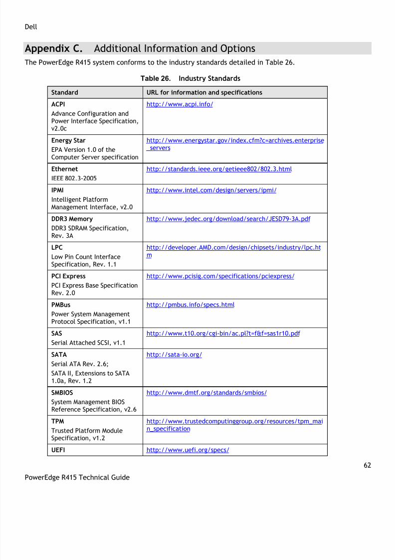
8/14/2019 r415 Tech Guide 11-18-10_final
http://slidepdf.com/reader/full/r415-tech-guide-11-18-10final 62/63
Dell
62
PowerEdge R415 Technical Guide
Appendix C. Additional Information and Options
The PowerEdge R415 system conforms to the industry standards detailed in Table 26.
Table 26. Industry Standards
Standard URL for information and specifications
ACPI
Advance Configuration andPower Interface Specification,v2.0c
http://www.acpi.info/
Energy Star
EPA Version 1.0 of theComputer Server specification
http://www.energystar.gov/index.cfm?c=archives.enterprise _servers
Ethernet
IEEE 802.3-2005
http://standards.ieee.org/getieee802/802.3.html
IPMI
Intelligent PlatformManagement Interface, v2.0
http://www.intel.com/design/servers/ipmi/
DDR3 Memory
DDR3 SDRAM Specification,Rev. 3A
http://www.jedec.org/download/search/JESD79-3A.pdf
LPC
Low Pin Count InterfaceSpecification, Rev. 1.1
http://developer.AMD.com/design/chipsets/industry/lpc.htm
PCI Express
PCI Express Base Specification
Rev. 2.0
http://www.pcisig.com/specifications/pciexpress/
PMBus
Power System ManagementProtocol Specification, v1.1
http://pmbus.info/specs.html
SAS
Serial Attached SCSI, v1.1
http://www.t10.org/cgi-bin/ac.pl?t=f&f=sas1r10.pdf
SATA
Serial ATA Rev. 2.6;
SATA II, Extensions to SATA1.0a, Rev. 1.2
http://sata-io.org/
SMBIOSSystem Management BIOSReference Specification, v2.6
http://www.dmtf.org/standards/smbios/
TPM
Trusted Platform ModuleSpecification, v1.2
http://www.trustedcomputinggroup.org/resources/tpm_main_specification
UEFI http://www.uefi.org/specs/
8/14/2019 r415 Tech Guide 11-18-10_final
http://slidepdf.com/reader/full/r415-tech-guide-11-18-10final 63/63
Dell
Standard URL for information and specifications
Unified Extensible FirmwareInterface Specification, v2.1
USB
Universal Serial BusSpecification, Rev. 2.0
http://www.usb.org/developers/docs/
Windows Logo Windows Logo ProgramSystem and DeviceRequirements, v3.10
http://www.microsoft.com/whdc/winlogo/hwrequirements.mspx


