A Step-by-Step Guide for Installion, Programming, and Operation Note: Please leave this manual with homeowner. RA-SBT-CHR, RB-SBT-CHR Setup and Installation Guide For a RadioRA® Chronos TM System Bridge and Timeclock R E A D F I R S T
Transcript
A Step-by-Step Guide for Installion, Programming, and Operation
Note: Please leave this manual with homeowner.
RA-SBT-CHR, RB-SBT-CHRSetup and Installation Guide For a RadioRA®
ChronosTM System Bridge and Timeclock
R E A D F I R S T
Setup Guide for the RadioRA Chronos System Bridge2
1. It is recommended that only one GRAFIK Eye® Control Unit be wired to each GRAFIK Eye Interface. Multiple GRAFIK EyeControl Units may be wired (linked) to the same GRAFIK Eye Interface, however, all GRAFIK Eye Control Units on thatlink will respond in unison to the commands from the GRAFIK Eye Interface. ALL GRAFIK Eye Control Units wired to thesame Interface will carry out ALL commands from the GRAFIK Eye Interface (i.e. go to GRAFIK Eye scene 3, Turn OFF,etc...). Interface commands cannot be sent to one individual GRAFIK Eye Control Unit on a link of multiple GRAFIK EyeControl Units.
• This application may be desired if multiple GRAFIK Eye Control Units are in the same room and it is intended thatthe same scene be selected on each GRAFIK Eye Control Unit simultaneously.
• Lutron does not recommend using one GRAFIK Eye Interface to linked GRAFIK Eye Control Units located in morethan one room.
2. Scene 1 on a GRAFIK Eye Control Unit is the default scene for ALL ON, SECURITY, and FLASH MODES. It is recom-mended that Scene 1 on GRAFIK Eye Control Units be set to full intensity with a fade time of zero seconds.
3. Setting the light levels for GRAFIK Eye scenes should be done prior to any operations in this Setup Guide.4. A GRAFIK Eye scene may be added to any RadioRA® Master Control button which has been previously programmed
without altering that buttons existing programming.5. See RadioRA Application Note No.48 (P/N 366-730) for steps to activate GRAFIK Eye scenes 5-16 from a RadioRA
Master Control.6. For information on integrating your RadioRA system with a photocell, telephone interface, shade motor control, etc... see
the RadioRA Application Notes on our web page at www.lutron.com/applicationnotes/index.html.7. RadioRA lighting control systems use radio frequency technology for communication. Currently, RadioRA lighting control
systems are available in two frequencies. To determine the frequency of a RadioRA product, examine the model numberon the product’s unit label. The labels are located on the side of all “wallbox” products, and on the bottom of all “tabletop”products.The second letter in all RadioRA model numbers indicates the product’s frequency. For example: RA-6D is an “A” fre-quency product, whereas RB-6D is a “B” frequency product.Note: Do not mix RadioRA “A” and “B” frequency products within the same system. Products with different frequenciesare not compatible. If you have any questions concerning the installation or operation of this product, please call the Lutron TechnicalSupport Center at 1-800-523-9466.
Important Application Notes
System Operation Notes
This guide replaces the Setup Guide (P/N 044-001) included with a system Repeater.
The installer should be aware of the following:1. In order to install the ChronosTM System Bridge as the Main Repeater in an existing system, all devices in the system must
be returned to their factory defaults prior to installation of the Chronos System Bridge.2. When using a Whole-home Button on a Master Control, there will be a delay between when the Whole-home Button is
pressed and when the scene activates. The delay will typically be approximately 2 seconds. This applies for scenes thatcontain zones of lighting in one system or in both systems. The delay does not apply when the button is activated via RS-232.
3. For Whole-home Buttons that contain lighting in both System 1 and System 2, the scene will activate one system at atime, with a delay in between. The delay is typically 3 seconds. The system that the Master Control is in determines whichhalf of the scene activates first.
4. Only unprogrammed Master Control buttons can be used as Whole-home Buttons. All local programming must be erasedfrom a Master Control button before it can be assigned as a Whole-home Button.
5. When using Cordless Tabletop Master Controls, the Master Control LEDs will not update when the Master Control is firstawakened from a “sleep” state.
6. When using Master Controls with Raise/Lower buttons with the Chronos System Bridge, the Raise/Lower buttons will notwork on Whole-home scenes.
Setup Guide for the RadioRA Chronos System Bridge 3
FCC InformationNote: This equipment has been tested and found to comply with the limits for a Class B digital device, pursuant to Part 15 of the FCC rules. These limits aredesigned to provide reasonable protection against harmful interference in a residential installation. This equipment generates, uses and can radiate radio frequencyenergy and, if not installed in accordance with the instructions, may cause harmful interference to radio communications. However, there is no guarantee that inter-ference will not occur in a particular installation. If this equipment does cause harmful interference to radio or television reception, which can be determined by turn-ing the equipment off and on, the user is encouraged to try to correct the interference by one or more of the following measures:
• Reorient or relocate the receiving antenna.• Increase the seperation between the equipment and receiver.• Connect the equipment into an outlet on a circuit different from that to which the receiver is connected.• Consult the dealer or an experienced radio/TV technician for help.
Caution: Changes or modifications not expressly approved by Lutron Electronics Co. could void the user’s authority to operate this equipment.
This symbol is intended to alert the user to the presence of important installation and operating instructions.
Consumer Information
DangerThis RadioRA® system must not be used to control equipment, other than lighting, which is not visible from every mas-ter or local control location. It also must not be used to control equipment which could create hazardous situationssuch as entrapment if operated accidentally. Examples of equipment which must not be controlled by this RadioRAsystem include (but are not limited to) motorized gates, garage doors, industrial doors, and microwave ovens, heatingpads, etc. It is the installer's responsibility to ensure that the equipment, other than lighting, being controlled is visiblefrom every master or local control location and that only suitable equipment is connected to this RadioRA system.
Using the ChronosTM System Bridge with Older RadioRA® Lighting Zone ControlsOn RadioRA Dimmers, Switches, and GRAFIK Eye® Interfaces shipped prior to January 1, 2001, the Legacy setting for fadetimes must be used. Raise/Lower functions from Master Controls and the Level Capture feature are also not supported bythese devices shipped prior to January 1, 2001.
Using the Chronos System Bridge with Older RadioRA Master Controls and InterfacesThe Chronos System Bridge Whole-home scenes will not work with Master Controls shipped prior to January 1, 2001. Thebuttons on these Master Controls do not send programming necessary to activate the Chronos System Bridge scenes. Also,this feature was not supported in RA-RS232 and RA-IR Interfaces shipped prior to September 1, 2001. For this reason,these older devices cannot be used to activate Whole-home scenes.
Using the RA-SCI Switch Closure InterfaceThe Switch Closure Interface cannot be used to activate Whole-home scenes. The security mode inputs on the SwitchClosure Interface will not work across systems. If a security system is connected to the RA-SCI security inputs, it should bemoved to the security input on the Chronos System Bridge. Refer to Section 6 for instructions on setting up the ChronosSystem Bridge contact closure inputs.
Using the RAMC-MFE-WH Security Mode InputsThe security mode input on the RAMC-MFE-WH will not work across systems. If a security system is connected to theRAMC-MFE-WH security input, it should be moved to the security input on the Chronos System Bridge. Refer to Section 6for instructions on setting up the Chronos System Bridge contact closure inputs.
Using Security mode from a RA-RS232 InterfaceSecurity mode activated from an RA-RS232 Interface will not work across systems. If a third-party system is connected to anexisting RA-RS232 Interface, it should be moved to the RS-232 port on the Chronos System Bridge. Refer to Section 5 forinstructions on setting up the Chronos System Bridge RS-232 port.
Compatibility Information
Setup Guide for the RadioRA Chronos System Bridge4
Using This GuideThis guide is divided into sections. Each section deals with a particular feature or set of features of theChronosTM System Bridge. Depending on the design of the RadioRA® system and the intended use for theChronos System Bridge, some sections may not apply. The figure below shows the sections containing criticalinformation for each listed feature, in the order that the sections should be read.
Section 1
Getting Started
Section 1
Getting Started
Section 1
Getting Started
Section 1
Getting Started
Section 4
Time ClockProgramming
Section 2
SystemActivation
Section 3
ButtonProgramming
Section 6
Contact ClosureProgramming
Section 3
ButtonProgramming
Section 5
RS-232Programming
Time ClockBridge / Main
Repeater RS-232Contact Closures
/ Security
Setup Guide for the RadioRA Chronos System Bridge 5
Table of ContentsSection 1 - Getting Started
System OverviewRadioRA System Components ........................................................................................................................7Chronos System Bridge Features ..................................................................................................................8System Layout ..................................................................................................................................................9Chronos System Bridge Hardware Identification ..........................................................................................11
Installing the ChronosInstallation ........................................................................................................................................................12Using the LCD and Buttons ............................................................................................................................15Using the Keyboard Port..................................................................................................................................16
System ConfigurationSystem Configuration and Features ..............................................................................................................17
Initial Chronos System Bridge ConfigurationSetting the Initial Chronos System Bridge Configuration ............................................................................18
Section 2 - System ActivationActivating the System
Local Button Programming Overview ............................................................................................................25ROOMS and SCENES Overview ......................................................................................................................26Local Buttons, Phantom Buttons, and Whole-home Buttons ......................................................................27
Local Button ProgrammingAssigning a Column of Buttons as ROOMS or SCENES..............................................................................28Assigning Lighting Zone Controls to Buttons ..............................................................................................30Setting Light Levels/GRAFIK Eye and GRAFIK RA Scene Selection for Buttons......................................32Programming the ALL ON and ALL OFF Buttons..........................................................................................34
Advanced Local ProgrammingCopying Local Button Programming ..............................................................................................................36Erasing Local Button Programming ..............................................................................................................38
Whole-home/Phantom Button ProgrammingSet Phantom Button Names ............................................................................................................................40Set Phantom Button Types (ROOM or SCENE) ............................................................................................41Assigning Lighting Zone Controls to Phantom Buttons ..............................................................................42Setting Light Levels/GRAFIK Eye Scene Selection for Phantom Buttons..................................................44Setting Button Properties for Phantom Buttons ..........................................................................................46Assigning Phantom Buttons to Master Controls ..........................................................................................47Testing Phantom Button Programming ..........................................................................................................48Erasing Phantom Button Programming ........................................................................................................48
Using the Button Copy FeatureCopying Existing Chronos Programming ......................................................................................................49Copying Programming from Master Controls to the Chronos System Bridge ..........................................50
Section 4 - Time Clock ProgrammingAstronomical Time Clock Programming
Setting the Chronos System Bridge Date and Time ....................................................................................52Creating Time Clock Scenes............................................................................................................................55Testing Time Clock Scenes..............................................................................................................................59Erasing Time Clock Scenes ............................................................................................................................60
Setup Guide for the RadioRA Chronos System Bridge6
Table of Contents - ContinuedAstronomical Time Clock Programming - Continued
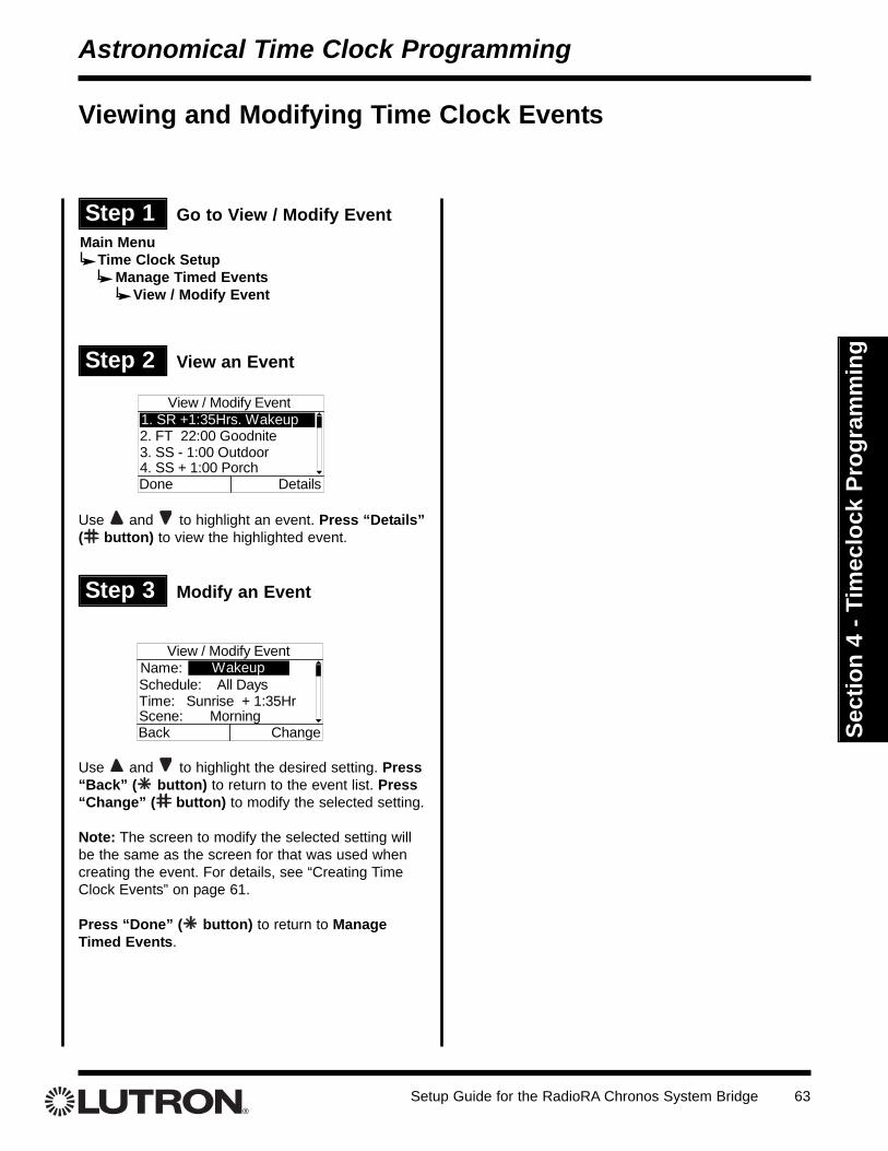
Creating Time Clock Events ............................................................................................................................61Viewing and Modifying Time Clock Events ....................................................................................................63Deleting a Time Clock Event............................................................................................................................64Setting the Time Clock Home / Away Mode ..................................................................................................65
Section 5 - RS-232 ProgrammingRS-232 Port Programming
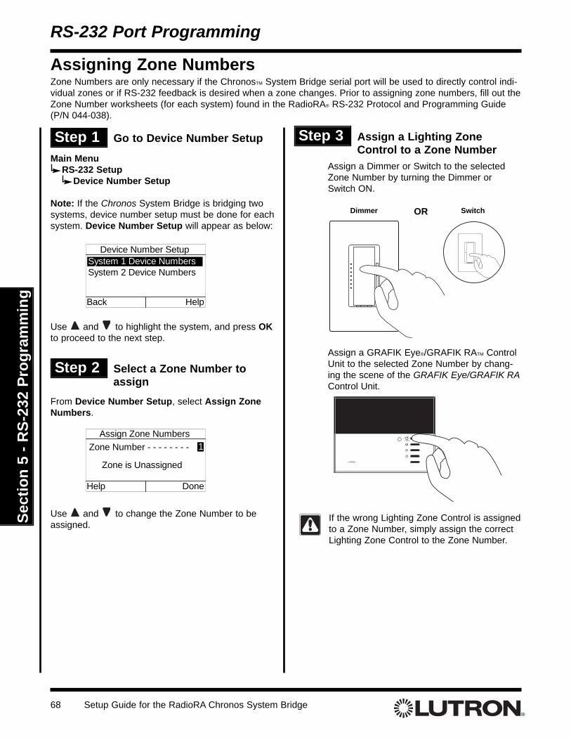
Overview ............................................................................................................................................................66Configuring the RS-232 Serial Port ................................................................................................................67Assigning Zone Numbers ................................................................................................................................68Assigning Master Control Numbers................................................................................................................70Phantom Button Programming........................................................................................................................72
Setting Up a General Purpose Contact Closure Input for Scene Control ..................................................73Setting Up a General Purpose Contact Closure Input for Time Clock Mode Control................................76Setting Up the Security Contact Closure Input..............................................................................................77Testing Contact Closure Inputs ......................................................................................................................79
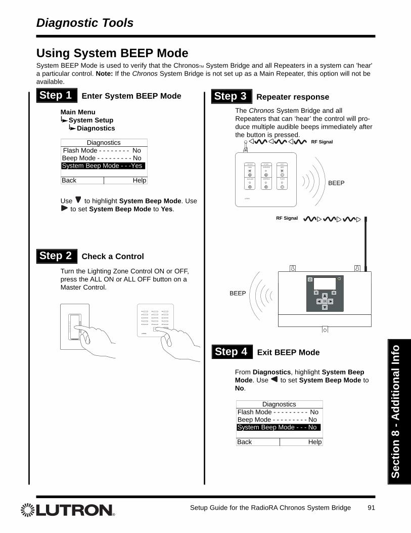
Viewing the Address Usage and Detecting Missing Devices ......................................................................84Viewing Device Information ............................................................................................................................86Using FLASH Mode ..........................................................................................................................................87Using BEEP Mode ............................................................................................................................................89Using System BEEP Mode ..............................................................................................................................91
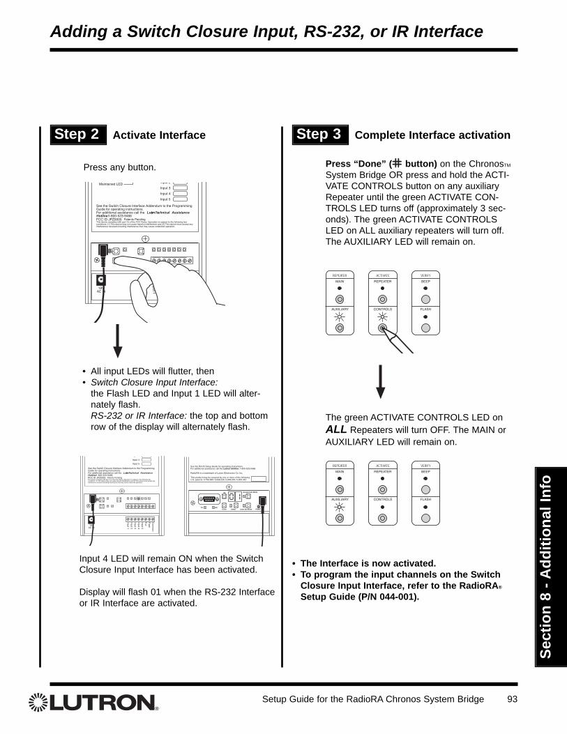
Adding a Switch Closure Input, RS-232, or IR InterfaceActivating a Switch Closure Input Interface, RS-232 Interface, or Infrared (IR) Interface ........................92
Using RadioRA Master Controls with Raise/LowerUsing RadioRA Master Controls with Raise/Lower ......................................................................................103
GlossaryDefinitions of Common Terms ........................................................................................................................104
Master Controls provide control of anyor all RadioRA Lighting Zone Controls.
Dimmer Switch LampDimmer
GRAFIK Eye PresetLighting Control
Wall-mounted Master Controls Multi-function Entry MasterControl and Visor Control
Transmitter
Tabletop Master Controls System Interface MasterControls—RS-232, SwitchClosures, and Infrared (IR)
RF Signal Repeater:
Repeaters provide system setup anddiagnostic functions, and provide anadditional path for communicationsbetween system devices.
Repeater
ChronosTM System Bridge andTimeclock:
The Chronos System Bridge providestimeclock capability, RS-232 and contact closure input interfacing, theability to bridge two RadioRA systems,and acts as a system’s Main Repeater.
Chronos System Bridgeand Timeclock
Setup Guide for the RadioRA Chronos System Bridge8
Sect
ion
2 - S
yste
m A
ctiv
atio
nSe
ctio
n 1
- Get
ting
Star
ted
ChronosTM System Bridge Features
System Overview
System BridgeThe Chronos System Bridge bridges two RadioRA® systems for a total of 64 Lighting ZoneControls and 24 Master Controls.
17 Whole-home ScenesThe Chronos System Bridge provides 17 whole-home scenes which can be accessed via anybutton on a Master Control or via the RS-232 connection.
Astronomic Time ClockThe time clock provides an additional 13 whole-home scenes that can be activated by up to100 programmable time clock events. These events can be scheduled relative to sunrise /sunset or time of day.
Contact Closure InputsOne security and two general-purpose contact closure inputs allow interfacing to security andother third-party systems.
LCD User InterfaceThe interactive LCD interface guides the user through setting up whole-home scenes, timeclock events, RS-232 device mapping, and other system settings.
Advanced DiagnosticsThe Chronos System Bridge provides advanced diagnostics through the LCD, simplifying sys-tem setup and troubleshooting.
Main RepeaterWhen bridging two systems, the Chronos System Bridge always acts as the Main Repeater inboth systems. The Chronos System Bridge may also act as the Main Repeater in a singlesystem.
RS-232 InterfaceThe RS-232 interface allows for integration with third-party systems.
Setup Guide for the RadioRA Chronos System Bridge 9
Sect
ion
1 - G
ettin
g St
arte
d
System Overview
System Layout
Step 1 Determine if Bridging is Required
Bridging is required if:• More than 32 Lighting Zone Controls exist, or• More than 12 Master Controls exist
Step 2 For Bridging Two Systems
For optimal light response time, devices in System 1 and System 2 should notbe used in the same room. Splitting the two systems, as shown below, is recommended.
Determine location of System 1 and System 2.Examples:
a. System 1: 1st Floor (see illustration below)System 2: 2nd Floor
b. System 1: East WingSystem 2: West Wing
c. System 1: InteriorSystem 2: Exterior
Setup Guide for the RadioRA Chronos System Bridge10
Sect
ion
1 - G
ettin
g St
arte
d Step 3 Repeater, ChronosTM System Bridge, Lighting Zone Controls,and Master Control Placement
Place the Chronos System Bridge and Repeaters to provide appropriate RF coverage withineach system.
Repeaters• Place System 1 Repeaters within 60 feet (18 m) of each other• Place System 2 Repeaters within 60 feet (18 m) of each other
Chronos System Bridge• Place the Chronos System Bridge within 60 feet (18 m) of a Repeater in each system
Lighting Zone Controls and Master Controls• Place System 1 Controls within 30 feet (9 m) of System 1 Repeaters or Chronos System
Bridge• Place System 2 Controls within 30 feet (9 m) of System 2 Repeaters or Chronos System
Bridge
System Overview
1st Floor View—System 1
60 ft. (18 m)maximum30 ft. (9 m) 30 ft. (9 m)
Setup Guide for the RadioRA Chronos System Bridge 11
Sect
ion
1 - G
ettin
g St
arte
d
ChronosTM System Bridge Hardware Identification
System Overview
1. Mounting TabThree mounting tabs (2 at top, 1 at bottom) for installation
2. LCD ScreenProvides a simple, menu-driven interface
3. Home ButtonReturns to the Home Screen from any other screen
4. Soft KeyPerforms the action listed in the bottom left corner of theLCD
5. RF AntennaOrient antenna vertically for best performance
6. LCD Power LED
7. Soft KeyPerforms the action listed in the bottom right corner of theLCD
8. Navigation ButtonsFor navigating menus and changing settings
9. RS-232 Activity LEDsIndicate when RS-232 communications are present
10. RS-232 PortFor communication with third-party systems
11. Contact Closure InputsFor interfacing to security and other systems
12. Initialization SwitchFor resetting the Chronos System Bridge
13. Keyboard PortFor navigation and data entry with a standard keyboard(PS/2-compatible connector)
14. RF Activity LEDsIndicate when RF communications are present
15. Power Input JackInput jack for use with the power adapter provided withthe Chronos System Bridge
16. Power LEDIndicates when the Chronos System Bridge is powered
Setup Guide for the RadioRA Chronos System Bridge12
Sect
ion
1 - G
ettin
g St
arte
d
Remove the port cover from the Chronos SystemBridge by gently pulling up on the front edge to disengage the snaps.
Attach Chronos System Bridge to wall using the wallanchors and screws provided.
Installing the ChronosTM System Bridge
InstallationRead all instructions completely before installation.
Important Installation Notes
1. Install in accordance with all national and localelectrical codes.
2. Use only the AC adapter provided by Lutron withyour Chronos System Bridge. Using an adapter notrated at the following specifications could damagethe Chronos System Bridge and possibly overheatthe AC adapter.
• Input: 120 V 50/60 Hz
• Output: 18 V / 300 mA Class 2
3. Operate in ambient temperatures between 32°F(0°C) and 104°F (40°C), 0-90% humidity, non-con-densing.
4. To clean, wipe with a clean damp cloth. DO NOTuse any chemical solutions.
5. DO NOT ground the Chronos System Bridge. DONOT mount the Chronos System Bridge in a metalenclosure.
6. Do not paint the Chronos System Bridge.
7. The range and performance of the RadioRASystem is highly dependent on a variety of com-plex factors such as:
• Distance between system components
• Geometry of the home
• Construction of walls separating systemcomponents
• Electrical equipment located near systemcomponents
Step 1 Find a suitable location for theChronos System Bridge
Place the Chronos System Bridge in a convenientand accessible location. Access to input and outputwiring should be considered when selecting themounting location. The Chronos System Bridgeshould be placed in an area where it cannot be inadvertently changed, and at a height inaccessible tochildren.
Note: Master Controls and Lighting Zone Controlsmust be located within 30 feet (9 m) of the ChronosSystem Bridge or an Auxiliary Repeater. AuxiliaryRepeaters must be located within 60 feet (18 m) ofthe Chronos System Bridge or one another. For moreinformation refer to “Repeater, Chronos SystemBridge, and Zone/Master Control Placement” on page10.
Step 2 Mount the Chronos SystemBridge
Note: For best performance, antennashould be oriented vertically.
Setup Guide for the RadioRA Chronos System Bridge 13
Sect
ion
1 - G
ettin
g St
arte
dStep 3 Wiring to Input Devices
Note:• Input devices can be driveway sensors,
photocells, security systems, etc.Contact Closure Compatibility: The input closuresare intended for use with devices that provide main-tained or momentary outputs in the form of dry con-tact closure or open collector outputs meeting the fol-lowing criteria:
• On saturation voltage: < 1.0 V at 2 mA• Off leakage current: < 10.0 µA at 12 V • Outputs must stay in the closed or open state for
at least 40 msec in order to be recognized by theChronos System Bridge
If there is any question as to whether the contact clo-sure device is compatible with these specifications,contact the manufacturer of that device.Contact Closure Wiring:Caution - DO NOT apply voltage between any twoterminals on the Chronos System Bridge contact clo-sure input terminal block. This will cause improperoperation and could damage the Chronos SystemBridge and the connected equipment.
Installing the ChronosTM System BridgeTM
Step 4 Connect the RS-232 Cable
Connect a DB9 male RS-232 cable to theRS-232 connector.
To select the proper RS-232 cable for yourapplication, see the RadioRA RS-232Protocol and Programming Guide (P/N 044-038).
SecuritySystem
Other EquipmentContact Closures
RS232 Connector
To External Device
DANGER -• Do not connect line voltage power to the
Chronos System Bridge.• Connecting line voltage power or improper
wiring can result in personal injury or damage to the Chronos System Bridge orto other equipment.
• All external control equipment must maintain Class 2 isolation.
Setup Guide for the RadioRA Chronos System Bridge14
Sect
ion
1 - G
ettin
g St
arte
d
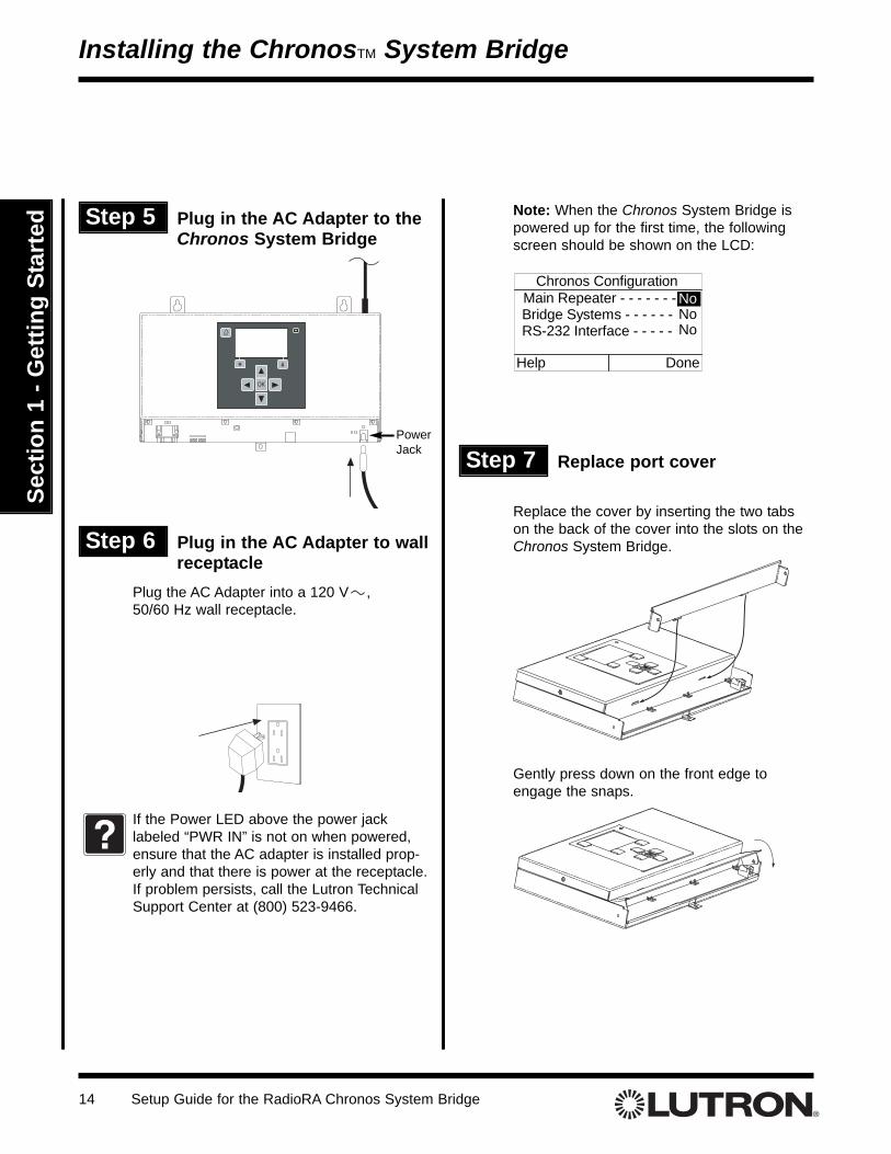
Replace the cover by inserting the two tabson the back of the cover into the slots on theChronos System Bridge.
Gently press down on the front edge toengage the snaps.
Step 6 Plug in the AC Adapter to wallreceptacle
Plug the AC Adapter into a 120 V , 50/60 Hz wall receptacle.
If the Power LED above the power jacklabeled “PWR IN” is not on when powered,ensure that the AC adapter is installed prop-erly and that there is power at the receptacle.If problem persists, call the Lutron TechnicalSupport Center at (800) 523-9466.
?
Installing the ChronosTM System Bridge
Step 5 Plug in the AC Adapter to theChronos System Bridge
PowerJack
Note: When the Chronos System Bridge ispowered up for the first time, the followingscreen should be shown on the LCD:
Setup Guide for the RadioRA Chronos System Bridge 15
Sect
ion
1 - G
ettin
g St
arte
d
Installing the ChronosTM System Bridge
Using the LCD and Buttons
Basic Navigation
Navigation through the menu system is very simple. The and buttons areused to highlight an item in a menu. The OK button is used to select the highlighteditem.
The and buttons are called soft keys. The function of the soft keys changesas indicated by the text directly above them on the LCD. Examples of soft key func-tions are “Back”, “Next”, “Help”, and “Cancel”.
The button is used to return to the home screen from any other screen. When on
the home screen, pressing will display the status screen.
Data EntryThere are 2 basic types of screens used for data entry.
On single-row edit screens, the and buttons are used to move from one
data field to another. The and buttons are used to change the value of thedata field.
On multi-row edit screens, the and buttons are used to move from one
data field to another. The and buttons are used to change the value ofthe data field.
On screens where data is being edited, the soft keys will always be “Cancel” and “Done”. The “Done”soft key must be used to confirm and accept changes.
Sleep ModeWhen the Chronos System Bridge has been idle for 30 minutes, the LCD will go into Sleep Mode. At thispoint, the LCD will turn off. A single press of any button will bring the LCD out of Sleep Mode.
Date
06 / 17 / 2003MM / DD / YYYY
Cancel Done
Serial Port SettingsBaud Rate - - - - - -Flow Control - -Hardware
9600
Cancel Done
Prompt - - - - - - - ONError Reporting - - - OFF
Setup Guide for the RadioRA Chronos System Bridge16
Sect
ion
1 - G
ettin
g St
arte
dInstalling the ChronosTM System Bridge
Using the Keyboard PortThe keyboard port is compatible with standard PS/2 keyboards with 6-pin mini-DIN connectors. A keyboard canbe connected to the Chronos System Bridge for navigation and data entry. The keys on the keyboard are usedas follows:
Keyboard Key Chronos Button Function
Change value or move to next orprevious item
Accept selection
Go to home screen
OR (on numeric keypad) Perform soft key function
OR (on numeric keypad) Perform soft key function
to (none)
+ to
to
+
(none) Back or Cancel(where available)
(none) Help
Space
Data Entry—characters/keys supported are A - Z, a - z, 0 - 9,Space, Backspace, Delete,#, %, &, *, (, ), -, _, ’, and :
Setup Guide for the RadioRA Chronos System Bridge 17
Sect
ion
1 - G
ettin
g St
arte
d
System Configuration
System Configuration and Features
Main Repeater*System 1Main Repeater*System 2Time ClockWhole-homeButtonsPhantom ButtonsContact ClosureInputsRS-232 Port
When using the Chronos System Bridge as the Main Repeater, all devices of an existing RadioRA® systemmust be reset to the factory default settings and reprogrammed.
*
System Maximums
System Configuration and Features Available
System Bridge(Chronos System
Bridge used as the MainRepeater* in both sys-
tems)
64
24
3
3
Single System(Chronos System
Bridge used as a MainRepeater*)
32
12
3
N/A
Single System(Chronos System Bridge
not used as a MainRepeater)
32
12
4
N/A
Bridged Systems(ChronosTM System
Bridge used as the MainRepeater* in both sys-
tems)
Single System(Chronos System
Bridge used as a MainRepeater*)
N/A
N/A
Single System(Chronos System
Bridge not used as aMain Repeater)
N/A
N/A
N/A
Setup Guide for the RadioRA Chronos System Bridge18
Sect
ion
2 - S
yste
m A
ctiv
atio
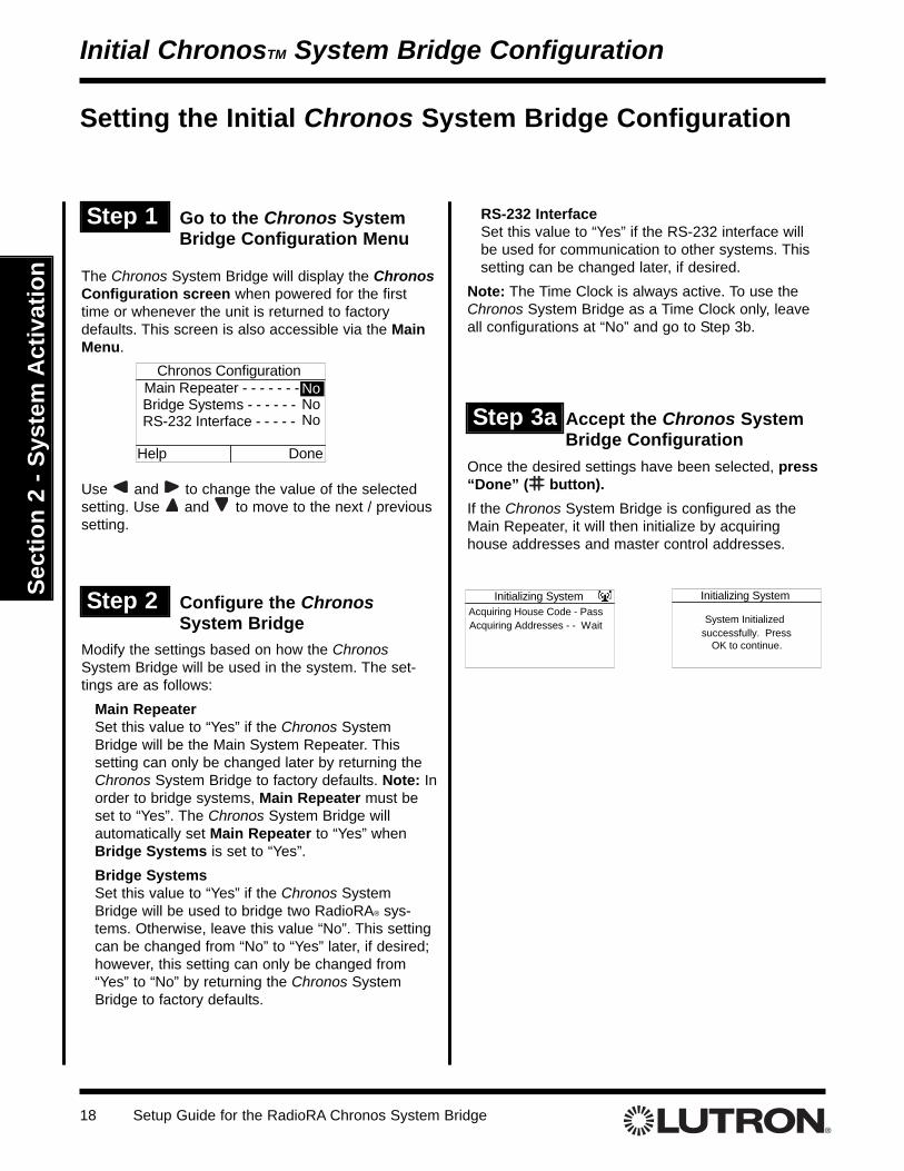
n The Chronos System Bridge will display the ChronosConfiguration screen when powered for the firsttime or whenever the unit is returned to factorydefaults. This screen is also accessible via the MainMenu.
Use and to change the value of the selectedsetting. Use and to move to the next / previoussetting.
Step 1 Go to the Chronos SystemBridge Configuration Menu
Initial ChronosTM System Bridge Configuration
Setting the Initial Chronos System Bridge Configuration
Modify the settings based on how the ChronosSystem Bridge will be used in the system. The set-tings are as follows:
Main RepeaterSet this value to “Yes” if the Chronos SystemBridge will be the Main System Repeater. This setting can only be changed later by returning theChronos System Bridge to factory defaults. Note: Inorder to bridge systems, Main Repeater must beset to “Yes”. The Chronos System Bridge will automatically set Main Repeater to “Yes” whenBridge Systems is set to “Yes”.Bridge SystemsSet this value to “Yes” if the Chronos SystemBridge will be used to bridge two RadioRA® sys-tems. Otherwise, leave this value “No”. This settingcan be changed from “No” to “Yes” later, if desired;however, this setting can only be changed from“Yes” to “No” by returning the Chronos SystemBridge to factory defaults.
Step 3a Accept the Chronos SystemBridge Configuration
Once the desired settings have been selected, press“Done” ( button). If the Chronos System Bridge is configured as theMain Repeater, it will then initialize by acquiringhouse addresses and master control addresses.
Initializing SystemAcquiring House Code - PassAcquiring Addresses - - Wait
Initializing System
System Initializedsuccessfully. Press
OK to continue.
RS-232 InterfaceSet this value to “Yes” if the RS-232 interface willbe used for communication to other systems. Thissetting can be changed later, if desired.
Note: The Time Clock is always active. To use theChronos System Bridge as a Time Clock only, leaveall configurations at “No” and go to Step 3b.
Setup Guide for the RadioRA Chronos System Bridge 19
Sect
ion
2 - S
yste
m A
ctiv
atio
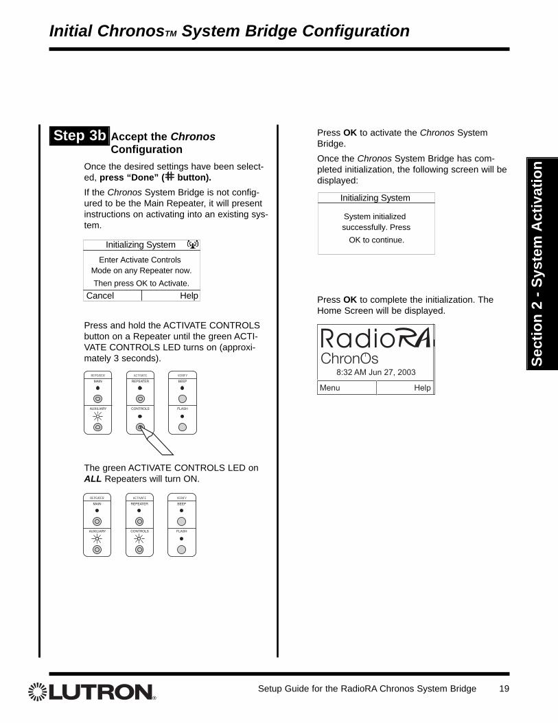
nOnce the desired settings have been select-ed, press “Done” ( button). If the Chronos System Bridge is not config-ured to be the Main Repeater, it will presentinstructions on activating into an existing sys-tem.
Press and hold the ACTIVATE CONTROLSbutton on a Repeater until the green ACTI-VATE CONTROLS LED turns on (approxi-mately 3 seconds).
The green ACTIVATE CONTROLS LED onALL Repeaters will turn ON.
Press OK to activate the Chronos SystemBridge.Once the Chronos System Bridge has com-pleted initialization, the following screen will bedisplayed:
Press OK to complete the initialization. TheHome Screen will be displayed.
Initializing System
System initializedsuccessfully. Press
OK to continue.
Initial ChronosTM System Bridge Configuration
Initializing SystemEnter Activate Controls
Mode on any Repeater now.
Cancel HelpThen press OK to Activate.
Step 3b Accept the ChronosConfiguration
Setup Guide for the RadioRA Chronos System Bridge20
Sect
ion
2 - S
yste
m A
ctiv
atio
nActivating the System
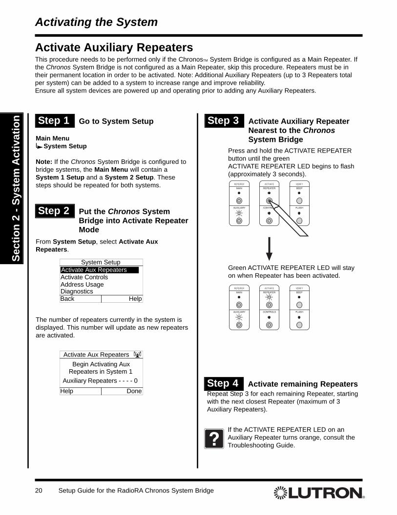
Step 1 Go to System Setup
Main MenuSystem Setup
Note: If the Chronos System Bridge is configured tobridge systems, the Main Menu will contain aSystem 1 Setup and a System 2 Setup. Thesesteps should be repeated for both systems.
Step 2 Put the Chronos SystemBridge into Activate RepeaterMode
From System Setup, select Activate AuxRepeaters.
The number of repeaters currently in the system isdisplayed. This number will update as new repeatersare activated.
Step 3 Activate Auxiliary RepeaterNearest to the ChronosSystem Bridge
Press and hold the ACTIVATE REPEATERbutton until the green ACTIVATE REPEATER LED begins to flash(approximately 3 seconds).
Green ACTIVATE REPEATER LED will stayon when Repeater has been activated.
System SetupActivate Aux RepeatersActivate ControlsAddress UsageDiagnosticsBack Help
Activate Aux RepeatersBegin Activating Aux
Repeaters in System 1Auxiliary Repeaters - - - - 0
Help DoneStep 4 Activate remaining RepeatersRepeat Step 3 for each remaining Repeater, startingwith the next closest Repeater (maximum of 3Auxiliary Repeaters).
If the ACTIVATE REPEATER LED on anAuxiliary Repeater turns orange, consult theTroubleshooting Guide.?
Activate Auxiliary RepeatersThis procedure needs to be performed only if the ChronosTM System Bridge is configured as a Main Repeater. Ifthe Chronos System Bridge is not configured as a Main Repeater, skip this procedure. Repeaters must be intheir permanent location in order to be activated. Note: Additional Auxiliary Repeaters (up to 3 Repeaters totalper system) can be added to a system to increase range and improve reliability.Ensure all system devices are powered up and operating prior to adding any Auxiliary Repeaters.
Setup Guide for the RadioRA Chronos System Bridge 21
Sect
ion
2 - S
yste
m A
ctiv
atio
n
Step 5 Complete Repeater activationPress “Done” ( button) on the ChronosTM SystemBridge. The green ACTIVATE REPEATER LED onALL auxiliary repeaters will turn off. The AUXILIARYLED will remain on.
• Repeater activation is now complete.• Proceed to Activate Controls on page 22.
Activating the System
Setup Guide for the RadioRA Chronos System Bridge22
Sect
ion
2 - S
yste
m A
ctiv
atio
nActivating the System
Step 1 Go to the System Setup Menu Step 3 Activate a Master ControlGo to any Master Control.
• Repeat Step 3 to activate any remainingMaster Controls.
Activate one Master Control at a time. Wait forthe middle row of LEDs to turn ON before acti-vating the next Master Control.
Press any button.• All LEDs will flutter, then• Top and bottom row will flash alternately
ALL ON
ALL OFF
Tabletop Master Wall MasterOR
Step 2 Put the System in ActivateControls Mode
From System Setup, select Activate Controls ORpress and hold the ACTIVATE CONTROLS button onany auxiliary Repeater until the green ACTIVATECONTROLS LED turns ON (approximately 3 sec-onds).
The number of devices and Master Controls currentlyin the system is displayed. These numbers willupdate as new Zone Controls and Master Controlsare activated. The green ACTIVATE CONTROLS LEDon ALL auxiliary repeaters will turn ON.
Activate ControlsBegin Activating
Controls in System 1Zone Controls - - - - - - - -0
Help DoneMaster Controls - - - - - - 0
?
Activate ControlsThis procedure needs to be performed only if the ChronosTM System Bridge is configured as a Main Repeater. Ifthe Chronos System Bridge is not configured as a Main Repeater, skip this procedure. All controls must be oper-ating (Dimmers and Switches must be wired to a light) in order to be activated.
System SetupActivate Aux RepeatersActivate ControlsAddress UsageDiagnosticsBack Help
Main MenuSystem Setup
Note: If the Chronos System Bridge is configured tobridge systems, the Main Menu will contain aSystem 1 Setup and a System 2 Setup. Thesesteps should be repeated for both systems.
The middle row of LEDs will turn ON when theMaster Control has been activated.
If a Master Control fails to respond asdescribed above, consult the TroubleshootingGuide.
Setup Guide for the RadioRA Chronos System Bridge 23
Sect
ion
2 - S
yste
m A
ctiv
atio
nGo to any Dimmer, Switch or GRAFIKEye®/GRAFIK RATM Control Unit. Turn theDimmer or Switch ON or OFF by pressing thetapswitch. On a GRAFIK Eye/GRAFIK RAControl Unit, change the selected scene bypressing a scene button.
The light(s) that the Lighting Zone Controloperates will turn ON and OFF a few timeswhen it has been activated.
If a Lighting Zone Control fails to respond asdescribed above, consult the TroubleshootingGuide.
Step 4 Activate a Lighting ZoneControl
Dimmer Switch
• Proceed to Step 5 when all Lighting ZoneControls have been activated.
Note: When a Lighting Zone Control is prop-erly activated, the Zone Controls count on theChronos System Bridge screen will incrementby one.
Activate one Lighting Zone Control at a time.Wait for the control to flash its light(s) beforeactivating any remaining controls.
• Repeat Step 4 to activate any remainingLighting Zone Controls.
?
TRON
OR
Activating the System
Step 5 Complete Control Activation
Press “Done” ( button) on the ChronosSystem Bridge OR press and hold the ACTI-VATE CONTROLS button on any auxiliaryRepeater until the green ACTIVATE CON-TROLS LED turns off (approximately 3 sec-onds). The green ACTIVATE CONTROLSLED on ALL auxiliary repeaters will turn off.The AUXILIARY LED will remain on.
Step 6 Verify that all Controls havebeen activated
From System Setup, select Diagnostics.
Use or to activate Flash Mode.
Master Controls, if activated, will flash alltheir LEDs. Make note of any Master Controlsthat are not activated.
Setup Guide for the RadioRA Chronos System Bridge24
Sect
ion
2 - S
yste
m A
ctiv
atio
n
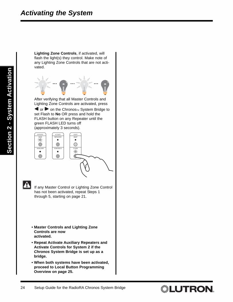
Lighting Zone Controls, if activated, willflash the light(s) they control. Make note ofany Lighting Zone Controls that are not acti-vated.
After verifying that all Master Controls andLighting Zone Controls are activated, press
or on the ChronosTM System Bridge toset Flash to No OR press and hold theFLASH button on any Repeater until thegreen FLASH LED turns off (approximately 3 seconds).
If any Master Control or Lighting Zone Controlhas not been activated, repeat Steps 1through 5, starting on page 21.
Activating the System
• Master Controls and Lighting ZoneControls are now activated.
• Repeat Activate Auxiliary Repeaters andActivate Controls for System 2 if theChronos System Bridge is set up as abridge.
• When both systems have been activated,proceed to Local Button ProgrammingOverview on page 25.
Setup Guide for the RadioRA Chronos System Bridge 25
Sect
ion
3 - B
utto
n Pr
ogra
mm
ing
Local Button Programming Overview
Button Programming Overview
1. Select a Master Control to be Programmed
2. Set ColumnsEach column of buttons on a Master Control can be programmed to be either ROOM or SCENE but-tons. All button columns are factory set as ROOM buttons. Refer to Rooms and Scenes Overview (page26) for an explanation of Rooms and Scenes. Refer to pages 28-29 for details on assigning a column ofbuttons as ROOMS or SCENES.
3. Program ROOM and SCENE ButtonsEach button on a Master Control can be programmed to affect any or all of the Lighting Zone Controls inthe system.a. Assign Controls
By default, ROOM and SCENE buttons have no controls assigned to them. To assign controls toeach button, perform the steps detailed on pages 30 and 31. Assign all Lighting Zone Controls thatwill be affected by the button being programmed. For SCENE Buttons, also assign all Lighting ZoneControls that will be turned OFF by the button being programmed.
b. Set Light LevelsLighting Zone Controls assigned to each button may be set to desired light levels to fit the mood oractivity programmed. To set light levels for each button, perform the steps detailed on pages 32 and33. Dimmer light levels default to 100% for ROOM Buttons and 50% for SCENE Buttons. Switchesdefault to ON and GRAFIK Eye®/GRAFIK RATM Control Units default to Scene 1.
4. Program ALL ON and ALL OFF ButtonsALL ON Buttons always turn ON Dimmers (to 100%), Switches, and GRAFIK Eye/GRAFIK RA ControlUnits (to Scene 1). ALL OFF Buttons always turn these controls OFF. By default, all Lighting ZoneControls are assigned to all of the ALL ON and ALL OFF Buttons. To unassign controls from the ALL ONand ALL OFF Buttons, perform the steps detailed on pages 34 and 35.
5. Repeat for all Master Controls
Advanced Local Button ProgrammingTo copy Local Button programming from one Master Control to another, perform the steps detailed onpage 36.To clear Local Button programming, perform the steps detailed on pages 38 and 39.
Setup Guide for the RadioRA Chronos System Bridge26
Sect
ion
3 - B
utto
n Pr
ogra
mm
ing
What is a Room Button?A Room button is used to monitor the On/Off status of a light or group of lights. For instance, in the Family Room, theRecessed Lights, Wall Sconces, and Accent Lights make up all the lights in the room. Assigning all of those lights to one but-ton would allow the monitoring of all those lights. If any of the lights are On, the Room button’s LED will be ON. Pressing thebutton will turn all of the lights in the room off. If all of the lights in the Family Room are Off, the LED will be off. Pressing thebutton will turn all of the lights in the room on to their pre-selected level.
What is a Scene Button?A Scene button is used to create a mood or emotion in a room. In a Family Room, a couple common scenes are watch "TV"and watch a "Movie." Pressing a Scene button sets the mood by setting all assigned Dimmers to their pre-selected level. AScene button’s LED on a Master Control will be on if, and only if, that Scene button was pressed on that Master Control. So,when a Scene button is pressed from a Master Control, the assigned lights will go to their pre-selected level (including Off)and the Scene button’s LED will turn on. Pressing the Scene button again will turn all of the lights assigned to that button off.A Scene button’s LED will remain on as long as all of the assigned lights are still at their pre-selected level. If a light changeslevel, either from another Master Control button or via local control, the Scene button’s LED will turn OFF.
Rooms and Scenes Overview
Button Programming Overview
Initially, all of the lights are OFF. Our ROOM button, called Family, is off becauseall of the lights in the Room are OFF. Our two SCENE buttons, TV and Movie, areoff because the lights are not at the pre-selected levels for those SCENES.
Pressing the Family button turns ON all of the lights assigned to the button. TheFamily LED turns ON because atleast one of the lights in the room is on.
Pressing the Movie SCENE will recall the lights to the Movie setting. As before,the Movie and Family LEDs are ON.
Now the Recessed Lights have been turned on by pressing the button on theDimmer. The lights are no longer at their pre-selected level for the Movie SCENEso the Movie LED turns OFF. The Family LED remains on because at least one ofthe lights in the ROOM is still ON.
The Family LED indicates that atleast one of the lights ROOM is still ON. To turnOFF all of the lights in the ROOM, press the Family button. With all of the lights inthe ROOM OFF, the Family LED turns OFF.
Pressing the TV button sets the mood for watching TV. In this SCENE, all of thelights in the room at set to 50%. Since the TV button was pressed and the lightsare on at their pre-selected level, the TV LED turns ON. The Family LED remainson because at least one of the lights in the ROOM is still ON.
Pressing the Movie button sets the mood for watching a movie. In this SCENE,the recessed lights and wall sconces turn OFF and the Accent Lights turn On to50%. The Movie SCENE is active so the Movie LED is ON. The lights are nolonger at their pre-selected level for watching TV so the TV SCENE turns OFF.Like before, the Family LED is still ON because atleast one of the lights in theROOM is still ON.
Pressing the Movie button again will turn all of the lights in the ROOM OFF. Thelights are no longer at their pre-selected level for the Movie SCENE so the MovieLED turns OFF. Since all of the lights in the ROOM are OFF, the Family LED turnsOFF.
ROOMS and SCENES Examples
Setup Guide for the RadioRA Chronos System Bridge 27
Sect
ion
3 - B
utto
n Pr
ogra
mm
ing
Local Buttons, Phantom Buttons, and Whole-home Buttons
Button Programming Overview
Local ButtonsA Local Button is a Master Control button used to activate zones of lighting within a single system. A LocalButton is programmed locally at the Master Control, or copied from a button on another Master Control. Any orall zones of lighting within the same system as the Master Control can be assigned to the button. Each columnof local buttons can be assigned as either ROOM buttons or SCENE buttons.A Local Button would typically be used when all of the lighting to be controlled by the button is in the same areaas the Master Control.
Phantom ButtonsA Phantom Button is a "virtual" button that resides in the ChronosTM System Bridge and is used to activate light-ing in a single system or both systems. Any or all zones of lighting within a single system or both systems canbe assigned to Phantom Buttons. Each Phantom button can be assigned as either a ROOM button or a SCENEbutton.Phantom Buttons can be activated via Master Control Whole-home Buttons (see below) or via the ChronosSystem Bridge RS-232 port.
Whole-home ButtonsWhole-home Buttons are available when using the Chronos System Bridge to bridge two RadioRA® systems. AWhole-home button is a Master Control button that can be used to activate zones of lighting in both systems.Programming of Whole-home Buttons is accomplished at the Chronos System Bridge with Phantom Buttons.A Whole-home Button would be used whenever lighting in both systems is to be controlled by a Master Control.
Setup Guide for the RadioRA Chronos System Bridge28
Sect
ion
3 - B
utto
n Pr
ogra
mm
ing
Step 2 Changing ROOM/SCENEassignments
Press the 1st button in a column to make thatcolumn a ROOM column, or press the 2ndbutton to make it a SCENE column.
ALL OFFALL ON
ROOMSSCENES
Shown: Settingleft most columnas SCENE buttons.
Assigning a Column of Buttons as ROOMS or SCENESEach column of buttons on a Master Control can be programmed to be either ROOM or SCENE buttons. All button columns are factory set as ROOM buttons. Refer to Rooms and Scenes Overview (page 26) for an expla-nation of Rooms and Scenes. For an overview of the Master Control programming process, refer to page 25.
Changing a column assignment from ROOM to SCENE (or vice versa) will delete all previous programming in that column of buttons.
If the first LED in acolumn is flashing, thebuttons in that columnare set as ROOM but-tons.
If the second LED in acolumn is flashing, thebuttons in that columnare set as SCENE but-tons.
Note: The bottom row of LED s will flash when exter-nal control is enabled. This feature needs to beenabled for Whole-home buttons to function.
Step 1 Begin ROOM/SCENE assignment
Simultaneously press and hold the 3rd, 5th,and ALL OFF buttons in the right most columnuntil an LED in each column of the MasterControl which you are programming begins toflash (approximately 3 seconds).
Note: On a 5 button Raise/Lower Wall Master,press and hold the 3rd, 5th, and Lower but-tons.
Tabletop Master Wall MasterOR
Local Button Programming
Setup Guide for the RadioRA Chronos System Bridge 29
Sect
ion
3 - B
utto
n Pr
ogra
mm
ing
Step 3 Complete ROOM/SCENEassignment
Simultaneously press and hold the 3rd, 5th,and ALL OFF buttons in the right most columnuntil the LEDs stop flashing (approximately 3seconds).
Note: On a 5 button Raise/Lower Wall Master,press and hold the 3rd, 5th, and Lower but-tons.
Step 4 Label columns
Apply the supplied ROOMS or SCENESlabels to the space provided over each buttoncolumn.
SCENES ROOMS ROOMS
• Proceed to Assigning Lighting Zone Controls toLocal Buttons on page 30.
Local Button Programming
Setup Guide for the RadioRA Chronos System Bridge30
Sect
ion
3 - B
utto
n Pr
ogra
mm
ing
Assigning Lighting Zone Controls to Local ButtonsEach button on a Master Control can be programmed to affect any or all of the Lighting Zone Controls in the sys-tem. By default, ROOM and SCENE buttons have no controls assigned to them. To assign controls to each but-ton, perform the following steps. For an overview of the Master Control programming process, refer to page 25.
Step 3 Assign Lighting ZoneControls
Assign Dimmers or Switches to the MasterControl button by turning the Controls ON.Assign all Dimmers and Switches to be affect-ed by this button. For SCENE Buttons,include Dimmers and Switches which are tobe turned OFF by the button.
Assign a GRAFIK Eye®/GRAFIK RATM ControlUnit to the Master Control button by pressingone of the GRAFIK Eye/GRAFIK RA ControlUnit scene buttons. Assign all GRAFIKEye/GRAFIK RA Control Units to be affectedby this button. For SCENE Buttons, includeGRAFIK Eye/GRAFIK RA Control Units whichare to be turned OFF by the button.
SwitchDimmer
OR
TRON
Notes:• GRAFIK Eye/GRAFIK RA Control Units will automat-
ically turn on to Scene 1 once assigned.• If the wrong Lighting Zone Control is assigned to a
Master Control button, turn the Lighting Zone ControlOFF to unassign it.
Step 1 Begin assigning LightingZone Controls to buttons
Simultaneously press and hold the 2nd and4th buttons in the right most column until theupper right LED begins to flash (approximate-ly 3 seconds).
Tabletop Master Wall MasterOR
Upper right LED flashes.
ALL ON
ALL OFF
Step 2 Select a ButtonPress the button to be programmed. Its LEDwill begin to flash.
GRAFIKEye/GRAFIK RA
Control Unit
Local Button Programming
Setup Guide for the RadioRA Chronos System Bridge 31
Sect
ion
3 - B
utto
n Pr
ogra
mm
ing
Step 5 Complete assigning LightingZone Controls
Step 4 Program additional buttons
• Proceed to Step 5 when all buttons on thisMaster Control have been programmed.
• Repeat Steps 1 through 5 for any additionalMaster Controls.
• Proceed to Setting Light Levels/GRAFIK EyeScene Selection for Local Buttons on page 32.
Repeat Steps 2 and 3 for any additional but-tons to be programmed.
Local Button Programming
Simultaneously press and hold the 2nd and4th buttons in the right most column until allLEDs begin to flutter (approximately 3 sec-onds).
Setup Guide for the RadioRA Chronos System Bridge32
Sect
ion
3 - B
utto
n Pr
ogra
mm
ing
Local Button Programming
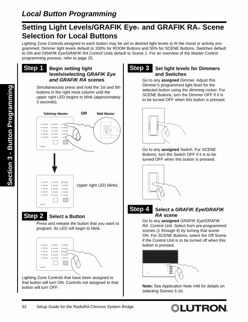
Setting Light Levels/GRAFIK Eye® and GRAFIK RA® SceneSelection for Local ButtonsLighting Zone Controls assigned to each button may be set to desired light levels to fit the mood or activity pro-grammed. Dimmer light levels default to 100% for ROOM Buttons and 50% for SCENE Buttons. Switches defaultto ON and GRAFIK Eye/GRAFIK RA Control Units default to Scene 1. For an overview of the Master Controlprogramming process, refer to page 25.
Step 1 Begin setting lightlevels/selecting GRAFIK Eyeand GRAFIK RA scenes
Simultaneously press and hold the 1st and 5thbuttons in the right most column until theupper right LED begins to blink (approximately3 seconds).
Step 3 Set light levels for Dimmersand Switches
Go to any assigned Dimmer. Adjust thisDimmer’s programmed light level for theselected button using the dimming rocker. ForSCENE Buttons, turn the Dimmer OFF if it isto be turned OFF when this button is pressed.
Tabletop Master Wall MasterOR
Upper right LED blinks.
Step 2 Select a ButtonPress and release the button that you want toprogram. Its LED will begin to blink.
Note: See Application Note #48 for details onselecting Scenes 5-16.
Step 4 Select a GRAFIK Eye/GRAFIKRA scene
Lighting Zone Controls that have been assigned tothat button will turn ON. Controls not assigned to thatbutton will turn OFF.
ALL ON
ALL OFF
Go to any assigned GRAFIK Eye/GRAFIKRA Control Unit. Select from pre-programmedscenes (1 through 4) by turning that sceneON. For SCENE Buttons, select the Off Sceneif the Control Unit is to be turned off when thisbutton is pressed.
Go to any assigned Switch. For SCENEButtons, turn the Switch OFF if it is to beturned OFF when this button is pressed.
Setup Guide for the RadioRA Chronos System Bridge 33
Sect
ion
3 - B
utto
n Pr
ogra
mm
ing
Local Button Programming
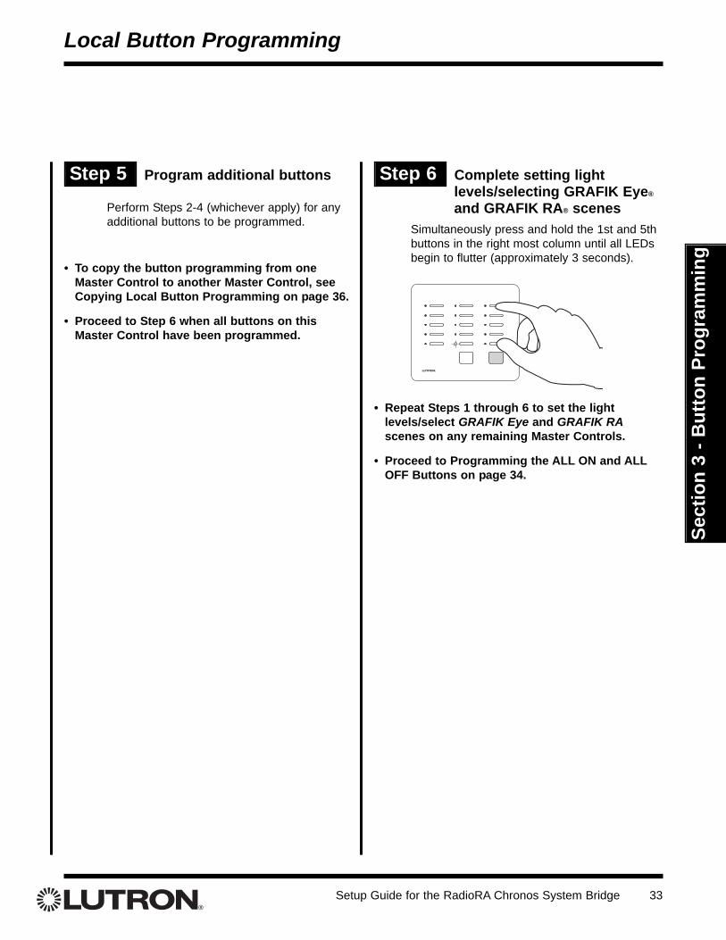
Step 6 Complete setting lightlevels/selecting GRAFIK Eye®
and GRAFIK RA® scenes
Step 5 Program additional buttons
• To copy the button programming from oneMaster Control to another Master Control, seeCopying Local Button Programming on page 36.
• Proceed to Step 6 when all buttons on thisMaster Control have been programmed.
Simultaneously press and hold the 1st and 5thbuttons in the right most column until all LEDsbegin to flutter (approximately 3 seconds).
• Repeat Steps 1 through 6 to set the lightlevels/select GRAFIK Eye and GRAFIK RAscenes on any remaining Master Controls.
• Proceed to Programming the ALL ON and ALLOFF Buttons on page 34.
Perform Steps 2-4 (whichever apply) for anyadditional buttons to be programmed.
Setup Guide for the RadioRA Chronos System Bridge34
Sect
ion
3 - B
utto
n Pr
ogra
mm
ing
Local Button Programming
Step 1 Begin the ALL ON/ALL OFFbutton programming
Programming the ALL ON and ALL OFF ButtonsALL ON Buttons always turn ON Dimmers (to 100%), Switches, and GRAFIK Eye®/GRAFIK RATM Control Units(to Scene 1). ALL OFF Buttons always turn these controls OFF. By default, all Lighting Zone Controls areassigned to all of the ALL ON and ALL OFF Buttons. To unassign controls from the ALL ON and ALL OFFButtons, perform the following steps. For an overview of the Master Control programming process, refer to page25.
Step 2 Select a button
On the Master Control to be programmed,simultaneously press and hold the 2nd and4th buttons in the right most column until theupper right LED begins to flash (approximate-ly 3 seconds).
Press the ALL ON or ALL OFF button on theMaster Control to be programmed.
Upper right LED flashes.
Tabletop Master OR
For the ALL ON button, the LEDs in allcolumns will simultaneously cycle from bottomto top.For the ALL OFF button, the LEDs in allcolumns will simultaneously cycle from top tobottom.
LEDs cycle UP forALL ON
All Lighting Zone Controls will turn on.
These programming steps only apply to MasterControls equipped with ALL ON and ALL OFFbuttons.
Wall Master
ALL ON
ALL OFF
LEDs cycle DOWNfor ALL OFF
Setup Guide for the RadioRA Chronos System Bridge 35
Sect
ion
3 - B
utto
n Pr
ogra
mm
ing
Local Button Programming
Step 3 Remove Lighting ZoneControls
Step 4 Complete the ALL ON andALL OFF button programming
Simultaneously press and hold the 2nd and4th buttons in the right most column until allLEDs begin to flutter (approximately 3 sec-onds).
Turn OFF the Lighting Zone Control(s) thatare to be removed from the ALL ON or ALLOFF button being programmed.
Dimmer
If the wrong Lighting Zone Control isremoved from the ALL ON or ALLOFF button, turn the Lighting ZoneControl ON to reassign it.
Switch
OR
TRON
• Repeat Steps 1 through 4 to re-program the ALLON and ALL OFF buttons on any additionalMaster Controls.
• The local button programming is now complete.
GRAFIK EyeControl Unit
• Repeat Steps 2 and 3 to program the remainingALL ON or ALL OFF button on the MasterControl.
Setup Guide for the RadioRA Chronos System Bridge36
Sect
ion
3 - B
utto
n Pr
ogra
mm
ing
Step 1 Begin Copying ButtonProgramming
Copying Local Button ProgrammingLocal Button programming can be copied from a button on one Master Control to a button on another MasterControl. To copy button programming, perform the following steps.
Note: The buttons may be copied as follows:• ROOM Buttons may be copied to ROOM Buttons• SCENE Buttons may be copied to SCENE Buttons
Step 2 Select the button to be programmed
Advanced Local Programming
On the Master Control to be programmed,simultaneously press and hold the 1st and 5thbuttons in the right most column until theupper right LED begins to blink (approximately3 seconds).
Press and release the button to be pro-grammed. Its LED will begin to blink.
Note: To copy to an ALL ON or ALL OFF button, you must enter Assignment Mode (but-tons 2 and 4) rather than Level Set Mode(buttons 1 and 5). Only SCENES may becopied to an ALL ON or ALL OFF button,never ROOMS. The ALL ON will still turnlights on to 100% and the ALL OFF button willstill turn lights off, but by copying, you maychoose which lights are affected. ALL ON andALL OFF buttons may also be copied to andfrom each other in the same way.
ALL ON
ALL OFF
Tabletop Master Wall MasterOR
Upper right LED blinks.
All LEDs on all otherMaster Controls willflash.
LED blinks.
Button to beprogrammed
Button to beprogrammed
Setup Guide for the RadioRA Chronos System Bridge 37
Sect
ion
3 - B
utto
n Pr
ogra
mm
ing
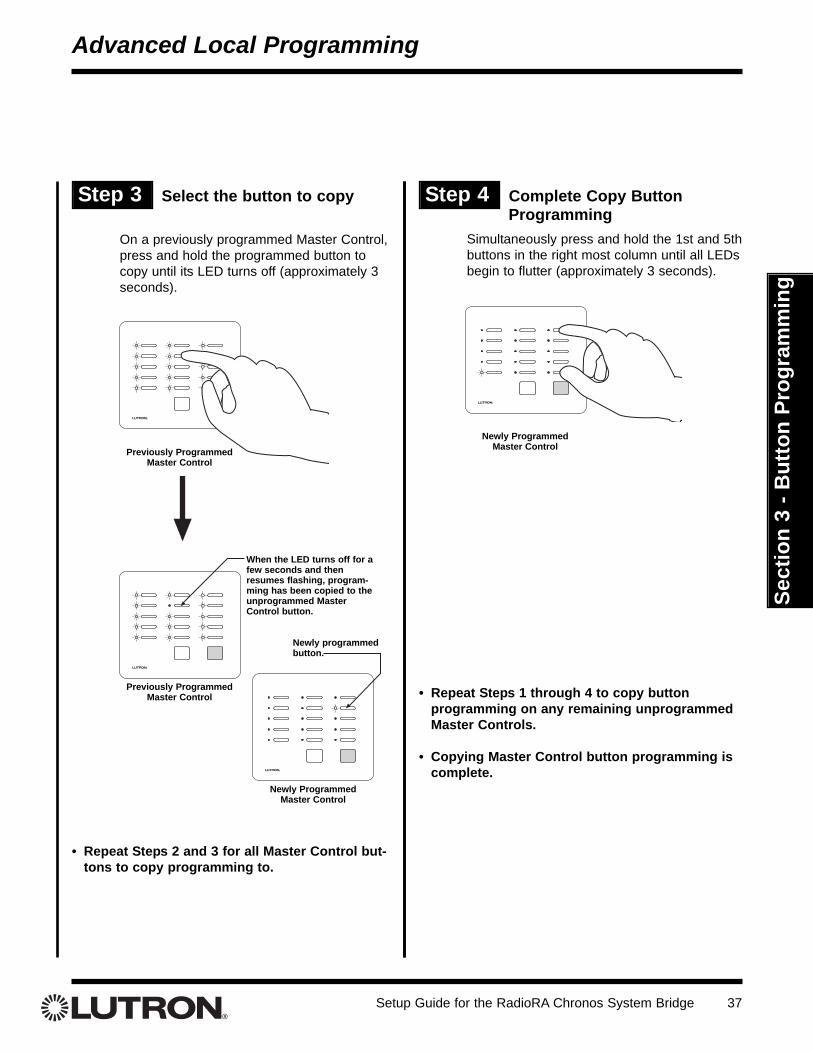
Step 3 Select the button to copy Step 4 Complete Copy ButtonProgramming
Advanced Local Programming
On a previously programmed Master Control,press and hold the programmed button tocopy until its LED turns off (approximately 3seconds).
Simultaneously press and hold the 1st and 5thbuttons in the right most column until all LEDsbegin to flutter (approximately 3 seconds).
• Repeat Steps 2 and 3 for all Master Control but-tons to copy programming to.
When the LED turns off for afew seconds and thenresumes flashing, program-ming has been copied to theunprogrammed MasterControl button.
Previously Programmed Master Control
Previously Programmed Master Control • Repeat Steps 1 through 4 to copy button
programming on any remaining unprogrammedMaster Controls.
• Copying Master Control button programming iscomplete.
Newly Programmed Master Control
Newly Programmed Master Control
Newly programmedbutton.
Setup Guide for the RadioRA Chronos System Bridge38
Sect
ion
3 - B
utto
n Pr
ogra
mm
ing
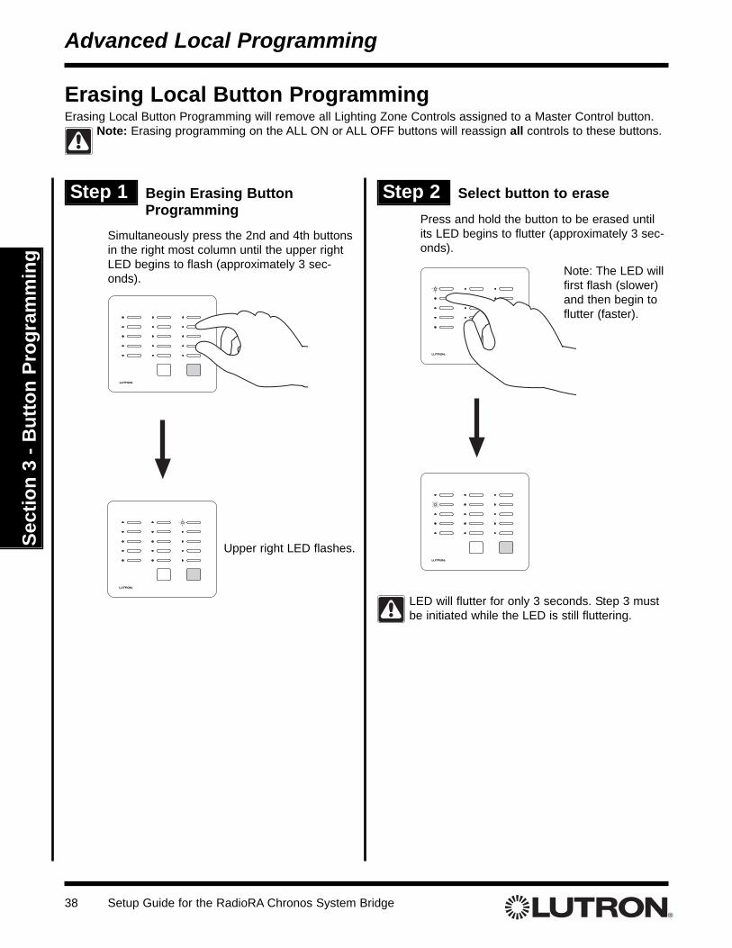
Erasing Local Button ProgrammingErasing Local Button Programming will remove all Lighting Zone Controls assigned to a Master Control button.
Note: Erasing programming on the ALL ON or ALL OFF buttons will reassign all controls to these buttons.
Advanced Local Programming
Step 1 Begin Erasing ButtonProgramming
Simultaneously press the 2nd and 4th buttonsin the right most column until the upper rightLED begins to flash (approximately 3 sec-onds).
Step 2 Select button to erase
Press and hold the button to be erased untilits LED begins to flutter (approximately 3 sec-onds).
Upper right LED flashes.
ALL OFFALL ONALL ON ALL OFF
LED will flutter for only 3 seconds. Step 3 mustbe initiated while the LED is still fluttering.
Note: The LED willfirst flash (slower)and then begin toflutter (faster).
Setup Guide for the RadioRA Chronos System Bridge 39
Sect
ion
3 - B
utto
n Pr
ogra
mm
ing
Advanced Local Programming
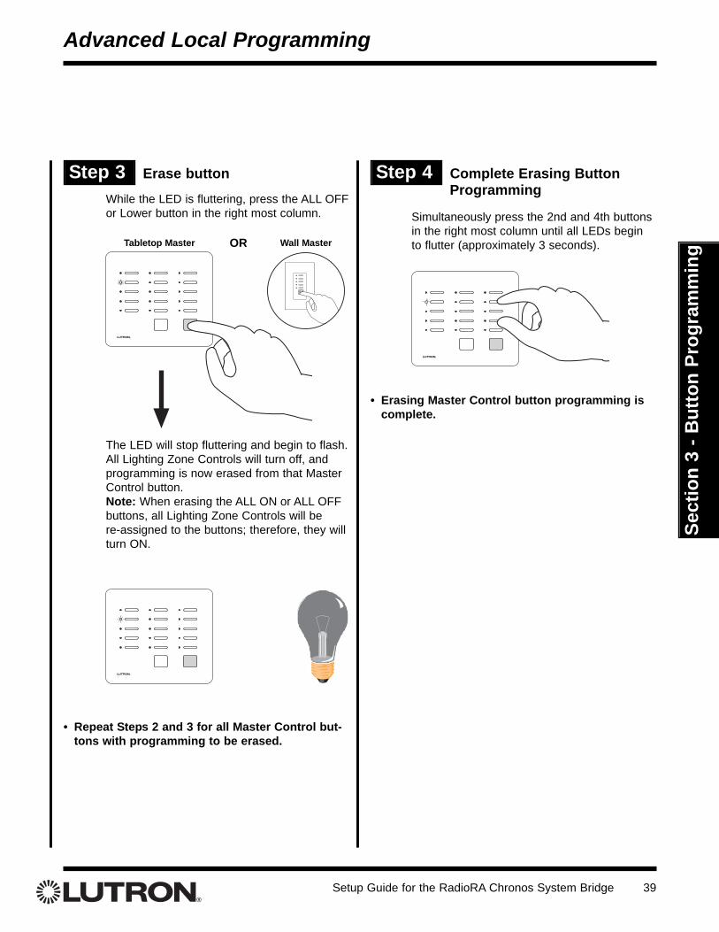
Step 3 Erase button
While the LED is fluttering, press the ALL OFFor Lower button in the right most column.
Step 4 Complete Erasing Button Programming
Simultaneously press the 2nd and 4th buttonsin the right most column until all LEDs beginto flutter (approximately 3 seconds).
The LED will stop fluttering and begin to flash.All Lighting Zone Controls will turn off, andprogramming is now erased from that MasterControl button.Note: When erasing the ALL ON or ALL OFFbuttons, all Lighting Zone Controls will be re-assigned to the buttons; therefore, they willturn ON.
• Repeat Steps 2 and 3 for all Master Control but-tons with programming to be erased.
Wall MasterTabletop Master OR
• Erasing Master Control button programming iscomplete.
Setup Guide for the RadioRA Chronos System Bridge40
Sect
ion
3 - B
utto
n Pr
ogra
mm
ing
Set Phantom Button NamesPhantom Buttons are "virtual" buttons that reside in the ChronosTM System Bridge and are used to activate light-ing in a single system or both systems.Whole-home Buttons are created by assigning Dimmers, Switches, or GRAFIK Eye® Control Units from 2 sys-tems to a single Phantom Button.Note: If the Chronos System Bridge is not configured to bridge systems or to use RS-232, Phantom Buttons arenot available and this procedure does not apply.
Whole-home/Phantom Button Programming
Step 1 Go to Phantom Button Setup
If bridging two systems:Main Menu
Whole-home Button SetupPhantom Button Setup
If not bridging systems:Main Menu
Phantom Button Setup
Step 2 Set Button Names
Phantom Button SetupSet Button Names
The list of phantom buttons is displayed:
Use and to select the button to name, andpress “Select” ( button).
Phantom Button SetupSet NamesSet Types to RM / SCAssign ZonesSet Zone LevelsBack Help
Using the , , , and keys, or an attachedkeyboard, change the button name to the desiredname. Press “Done” ( button) when finished.
Set Name
Name: _ _ _ _ _ _ _ _
Cancel Done
H o m e
Setup Guide for the RadioRA Chronos System Bridge 41
Sect
ion
3 - B
utto
n Pr
ogra
mm
ing
Set Phantom Button Types (ROOM or SCENE)Note: If the ChronosTM System Bridge is not configured to bridge systems or to use RS232, Phantom Buttons arenot available and this procedure does not apply.
Whole-home/Phantom Button Programming
Step 1 Set Button TypesIf bridging two systems:Main Menu
Whole-home Button SetupPhantom Button Setup
Set Types to RM / SCIf not bridging systems:Main Menu
Phantom Button SetupSet Types to RM / SC
Use the and buttons to highlight a PhantomButton. Press “Select” ( button) to change select-ed button from ROOM to SCENE or SCENE toROOM.
Note: Changing the button type will erase any pro-gramming currently on the button. If there is program-ming on the button, the following confirmation screenwill be displayed when “Select” ( button) ispressed:
Press “Yes”( button) to confirm the change, or “Cancel” (button) to cancel the change.
Note: The ALL ON and ALL OFF buttons (PhantomButtons 16 and 17) can only be SCENES.
CAUTION – THIS WILL ERASE ALLPROGRAMMING ON THIS BUTTON
Step 2 Select Phantom Button
Setup Guide for the RadioRA Chronos System Bridge42
Sect
ion
3 - B
utto
n Pr
ogra
mm
ing
Use and to highlight a Phantom Button. Press“Select” ( button) to enter Assignment Mode forthe highlighted button. The following screen will bedisplayed when Assignment Mode is initiated:
Once Assignment Mode has been initiated, the follow-ing screen will be displayed:
Note: To use the Copy Button Feature, refer to pages49-51.
Assigning Lighting Zone Controls to Phantom ButtonsNote: If the ChronosTM System Bridge is not configured to bridge systems or to use RS-232, Phantom Buttonsare not available and this procedure does not apply.
Step 3 Assign Lighting ZoneControls to the PhantomButton
Assign Dimmers or Switches to the PhantomButton by turning the Controls ON. Assign allDimmers and Switches to be affected by thisbutton. For SCENE Buttons, include Dimmersand Switches which are to be turned OFF bythe button.
Assign a GRAFIK Eye®/GRAFIK RATM ControlUnit to the Phantom Button by pressing one ofthe GRAFIK Eye/GRAFIK RA Control Unitscene buttons. Assign all GRAFIKEye/GRAFIK RA Control Units to be affectedby this button. For SCENE Buttons, includeGRAFIK Eye/GRAFIK RA Control Units whichare to be turned OFF by the button.
SwitchDimmer
OR
TRON
Notes:• GRAFIK Eye/GRAFIK RA Control Units will automati-
cally turn on to Scene 1 once assigned.• If the wrong Lighting Zone Control is assigned to a
Phantom Button, turn the Lighting Zone Control OFFto unassign it.
GRAFIK EyeControl Unit
Setup Guide for the RadioRA Chronos System Bridge 43
Sect
ion
3 - B
utto
n Pr
ogra
mm
ing
Whole-home/Phantom Button Programming
Step 4 Select next Phantom Button
Press “Continue” ( button) to display the list ofPhantom Buttons:
Note: The system is still in Assignment Mode, as indi-cated by the icon in the upper right hand corner of the screen. The arrow on the right of thescreen indicates which Phantom Button is currently inAssignment Mode.
Use the and buttons to select a PhantomButton. Press “Select” ( button) to enterAssignment Mode for the selected Phantom Button.
Repeat Steps 3 and 4 for any additional PhantomButtons.
Press “Exit” ( button) to finish assigning zones.
• Proceed to Setting Light Levels/GRAFIK Eye®
and GRAFIK RATM Scene Selection for PhantomButtons on page 44.
Setup Guide for the RadioRA Chronos System Bridge44
Sect
ion
3 - B
utto
n Pr
ogra
mm
ing
Setting Light Levels/GRAFIK Eye® and GRAFIK RATM
Scene Selection for Phantom ButtonsNote: If the ChronosTM System Bridge is not configured to bridge systems or to use RS-232, Phantom Buttonsare not available and this procedure does not apply. Dimmers can be set to a variable light level or turned off.Switches can be turned on or off. GRAFIK Eye Control Units can be set to any scene or turned off.
Use and to highlight a Phantom Button. Press“Select” ( button) to enter Level Set Mode for thehighlighted button. The following screen will be dis-played while Level Set Mode is initiated:
Once Level Set Mode has been initiated, the followingscreen will be displayed:
Note: To use the Copy Button Feature, refer to pages49-51.
Set Zone LevelsSet light levels for
devices assigned toHome.
ContinueCopy Button
Set Zone Levels
Entering Level SetMode...
Step 2 Select Phantom Button
Step 3 Set light levels for Dimmers
For ROOM Phantom Buttons, use the dim-ming rocker to adjust the light level of anyDimmer(s) assigned to the Phantom Button.This is the light level that the Dimmers willturn on to when the ROOM button is pressedon.
For SCENE Phantom Buttons, use the dim-ming rocker to adjust the light level of anyDimmer(s) assigned to the Phantom ButtonOR use the toggle button to turn the dimmeroff if it is to be turned OFF when the PhantomButton is activated.
While setting light levels• Dimmers assigned to a ROOM Phantom
Button cannot be turned off.• Dimmers not assigned to this Phantom But-
ton cannot be turned on.
Setup Guide for the RadioRA Chronos System Bridge 45
Sect
ion
3 - B
utto
n Pr
ogra
mm
ing
While setting light levels• GRAFIK Eye Control Units assigned to a
ROOM Phantom Button cannot be turnedOFF.
• GRAFIK Eye Control Units not assigned tothis Phantom Button cannot be turned ON.
Step 4 Select a GRAFIK Eye® scene
For ROOM Phantom Buttons, select one ofthe Scenes (1 through 4) on a GRAFIK EyeControl Unit by turning that Scene ON.
For SCENE Phantom Buttons, select one ofthe Scenes on a GRAFIK Eye Control Unit byturning that Scene ON OR select the OffScene on the GRAFIK Eye Control Unit if it isto be turned OFF when the Phantom Button isactivated.
Step 5 Select next Phantom Button
Press “Continue” ( button) to display the list ofPhantom Buttons:
Note: The system is still in Level Set Mode, as indi-cated by the icon in the upper right hand corner of thescreen. The arrow on the right of the screen indicateswhich Phantom Button is currently in Level Set Mode.
Use the and buttons to highlight a PhantomButton. Press “Select” ( button) to enter LevelSet Mode for the highlighted Phantom Button.
Repeat Steps 3 and 4 for any additional PhantomButtons.
Press “Exit” ( button) to exit Level Set Mode.
• Proceed to Setting Button Properties forPhantom Buttons on page 46.
Set Zone Levels1. RM - Home2. RM - Btn 23. RM - Btn 34. RM - Btn 4Exit Select
Whole-home Button Programming
Setup Guide for the RadioRA Chronos System Bridge46
Sect
ion
3 - B
utto
n Pr
ogra
mm
ing
Setting Button Properties for Phantom ButtonsNote: If the ChronosTM System Bridge is not configured to bridge systems or to use RS-232, Phantom Buttonsare not available and this procedure does not apply.
Whole-home/Phantom Button Programming
Step 1 Go to Set Properties
Use and to highlight a Phantom Button. Press“Select” ( button) to set button properties for thehighlighted button. The following screen will be dis-played:
Use and to change the value of the selectedsetting. Use and to select the next / previoussetting.
Fade Time determines the fade time of the selectedscene. The options are Default (1 second ON, 3 sec-onds OFF), 1 second, 3 seconds, 10 seconds, 30 sec-onds, 1 minute, 4 minutes, and Legacy.
If the system contains Dimmers, Switches, orGRAFIK Eye® Interfaces that were manufac-tured prior to January 1, 2001, the Legacysetting MUST be used.
Switches determines whether any switches in theselected scene operate:
• First On / First Off (FO/FO)• First On / Last Off (FO/LO).• Last On / First Off (LO/FO)• Last On / Last Off (LO/LO).
The options for Action are Toggle and Single Action.When activating a Toggle Phantom Button from aMaster Control, a button press will turn the scene:
• ON if it is OFF• OFF if it is ON
When activating a Single Action Phantom Button froma Master Control, a button press will always turn thescene ON.
Press “Done” ( button) when changes are com-plete.
• Repeat for any additional Phantom Buttons.
Step 2 Select Phantom Button
Setup Guide for the RadioRA Chronos System Bridge 47
Sect
ion
3 - B
utto
n Pr
ogra
mm
ing
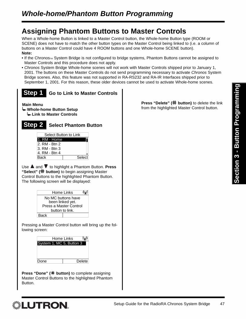
Assigning Phantom Buttons to Master ControlsWhen a Whole-home Button is linked to a Master Control button, the Whole-home Button type (ROOM orSCENE) does not have to match the other button types on the Master Control being linked to (i.e. a column ofbuttons on a Master Control could have 4 ROOM buttons and one Whole-home SCENE button). Note: • If the ChronosTM System Bridge is not configured to bridge systems, Phantom Buttons cannot be assigned to
Master Controls and this procedure does not apply.• Chronos System Bridge Whole-home scenes will not work with Master Controls shipped prior to January 1,
2001. The buttons on these Master Controls do not send programming necessary to activate Chronos SystemBridge scenes. Also, this feature was not supported in RA-RS232 and RA-IR Interfaces shipped prior toSeptember 1, 2001. For this reason, these older devices cannot be used to activate Whole-home scenes.
Whole-home/Phantom Button Programming
Step 1 Go to Link to Master Controls
Use and to highlight a Phantom Button. Press“Select” ( button) to begin assigning MasterControl Buttons to the highlighted Phantom Button.The following screen will be displayed:
Pressing a Master Control button will bring up the fol-lowing screen:
Press “Done” ( button) to complete assigningMaster Control Buttons to the highlighted PhantomButton.
Press “Delete” ( button) to delete the linkfrom the highlighted Master Control button.
Setup Guide for the RadioRA Chronos System Bridge48
Sect
ion
3 - B
utto
n Pr
ogra
mm
ing
Step 2 Select the Phantom Button toerase
Use and to highlight the Phantom Button toerase. Press “Select” ( button) to proceed to thenext step.
Step 1 Go to Phantom Button Setup
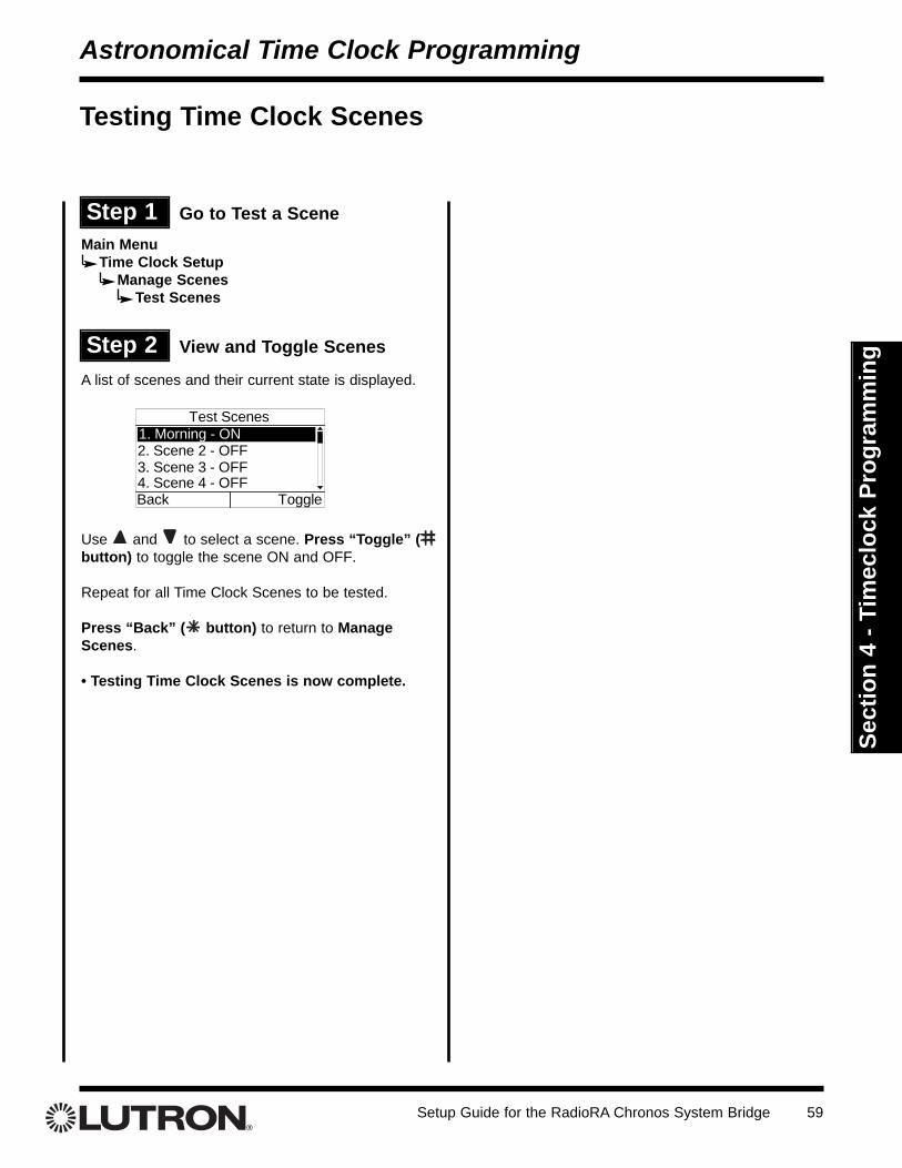
Testing and Erasing Phantom Button Programming
Note: If the ChronosTM System Bridge is not configured to bridge systems or to use RS-232, Phantom Buttonsare not available and this procedure does not apply.
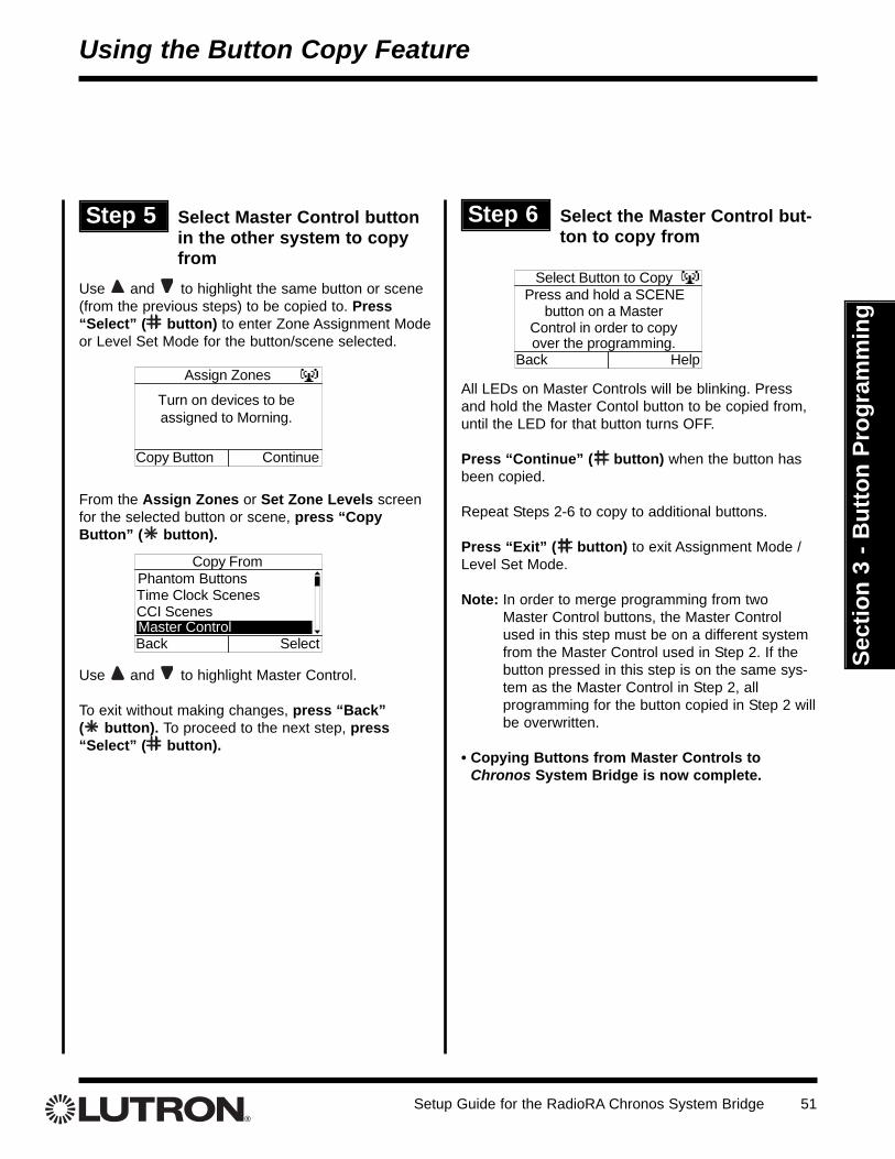
Copying Existing ChronosTM System Bridge ProgrammingButton copy is used to copy all programming from one button to another button. The Button Copy feature isavailable from the Assign Zones and Set Zone Levels screens for Phantom Buttons, Time Clock Scenes, andCCI Scenes. Note: ROOM Buttons may only be copied to ROOM Buttons, and SCENE Buttons may only be copied toSCENE Buttons.
Using the Button Copy Feature
Step 1 Go to Assign Zones or SetZone Levels
Phantom Buttons:If bridging two systems:Main Menu
Whole-home Button SetupPhantom Button Setup
Assign Zones or Set Zone LevelsIf not bridging two systems:Main Menu
Phantom Button SetupAssign Zones or Set Zone Levels
Time Clock Scenes:Main Menu
Time Clock SetupManage Scenes
Assign Zones or Set Zone LevelsContact Closure Input (CCI) Scenes:
Main MenuContact Closure Setup
CCI 1 or CCI 2 or Security SetupAssign Zones or Set Zone Levels (CCI 1,CCI 2) or Full Zone Assign / Flash ZoneAssign (Security)
Step 2 Select button or scene tocopy to
Use and to highlight the button or scene to becopied to. Press “Select” ( button) to enter ZoneAssignment Mode or Level Set Mode for thebutton/scene selected.
Assign Zones
Turn on devices to beassigned to Morning.
Copy Button Continue
Step 3 Select the type of button orscene to copy from
From the Assign Zones or Set Zone Levels screenfor the selected button or scene, press “CopyButton” ( button).
Use and to highlight the type of button or sceneto be copied from. Highlight Phantom Buttons, TimeClock Scenes, or CCI Scenes.
To exit without making changes, press “Back” ( button). To proceed to the next step, press“Select” ( button).
Use and to highlight the button or scene to becopied from.
To exit without making changes, press “Back” ( button). To copy the programming from the highlighted item, press “Copy” ( button).
Press “Continue” ( button) when the button hasbeen copied.
Repeat Steps 2-4 for additional buttons to be copied.
Press “Exit” ( button) to exit Assignment Mode /Level Set Mode.
Select Button to Copy1. Scene 012. Scene 023. Scene 034. Scene 04Back Copy
Setup Guide for the RadioRA Chronos System Bridge 49
Sect
ion
3 - B
utto
n Pr
ogra
mm
ing
Copying Programming from Master Controls to theChronosTM System BridgeThe Button Copy feature can be used to copy programming from a Master Control button to a Button / Scene onthe Chronos System Bridge. When using the Chronos System Bridge to bridge two systems, Button Copy can beused to merge programming from one Master Control button in each system onto one Button / Scene on theChronos System Bridge. Note: ROOM Buttons may only be copied to ROOM Buttons, and SCENE Buttons mayonly be copied to SCENE Buttons.
Using the Button Copy Feature
Step 1 Go to Assign Zones or SetZone Levels
Phantom Buttons:If bridging two systems:Main Menu
Whole-home Button SetupPhantom Button Setup
Assign Zones or Set Zone LevelsIf not bridging two systems:Main Menu
Phantom Button SetupAssign Zones or Set Zone Levels
Time Clock Scenes:Main Menu
Time Clock SetupManage Scenes
Assign Zones or Set Zone LevelsContact Closure Input (CCI) Scenes:
Main MenuContact Closure Setup
CCI 1 or CCI 2 or Security SetupAssign Zones or Set Zone Levels (CCI 1,CCI 2) or Full Zone Assign / Flash ZoneAssign (Security)
Step 2 Select button or scene tocopy to
Use and to highlight the button or scene to becopied to. Press “Select” ( button) to enter ZoneAssignment Mode or Level Set Mode for thebutton/scene selected.
Assign Zones
Turn on devices to beassigned to Morning.
Copy Button Continue
Step 3 Select the type of button orscene to copy from
From the Assign Zones or Set Zone Levels screenfor the selected button or scene, press “CopyButton” ( button).
Use and to highlight Master Control.
To exit without making changes, press “Back” ( button). To proceed to the next step, press“Select” ( button).
Step 4 Select the Master Control button to copy from
All LEDs on Master Controls will be blinking. Pressand hold the Master Contol button to be copied from,until the LED for that button turns OFF.
Press “Continue” ( button) when the button hasbeen copied.Repeat Steps 2-4 for additional buttons to be copied.
Press “Exit” ( button) to exit Assignment Mode /Level Set Mode.
To merge additional programming from a MasterControl button in the other system (when bridgingonly), continue to Step 5.
Select Button to CopyPress and hold a SCENE
button on a MasterControl in order to copyover the programming.
Back Help
Setup Guide for the RadioRA Chronos System Bridge50
Sect
ion
3 - B
utto
n Pr
ogra
mm
ing
Setup Guide for the RadioRA Chronos System Bridge 51
Sect
ion
3 - B
utto
n Pr
ogra
mm
ing
Using the Button Copy Feature
Step 5 Select Master Control buttonin the other system to copyfrom
Use and to highlight the same button or scene(from the previous steps) to be copied to. Press“Select” ( button) to enter Zone Assignment Modeor Level Set Mode for the button/scene selected.
From the Assign Zones or Set Zone Levels screenfor the selected button or scene, press “CopyButton” ( button).
Use and to highlight Master Control.
To exit without making changes, press “Back” ( button). To proceed to the next step, press“Select” ( button).
Step 6 Select the Master Control but-ton to copy from
All LEDs on Master Controls will be blinking. Pressand hold the Master Contol button to be copied from,until the LED for that button turns OFF.
Press “Continue” ( button) when the button hasbeen copied.
Repeat Steps 2-6 to copy to additional buttons.
Press “Exit” ( button) to exit Assignment Mode /Level Set Mode.
Note: In order to merge programming from twoMaster Control buttons, the Master Controlused in this step must be on a different systemfrom the Master Control used in Step 2. If thebutton pressed in this step is on the same sys-tem as the Master Control in Step 2, all programming for the button copied in Step 2 willbe overwritten.
• Copying Buttons from Master Controls toChronos System Bridge is now complete.
Select Button to CopyPress and hold a SCENE
button on a MasterControl in order to copyover the programming.
Back Help
Setup Guide for the RadioRA Chronos System Bridge52
Sect
ion
4 - T
imec
lock
Pro
gram
min
g
Setting the ChronosTM System Bridge Date and Time
Astronomical Time Clock Programming
Step 1 Go to Time / Date Settings
Step 2 Set the System Time
From Time / Date Settings, select Time.
Use and to change the selected field. Use and to highlight the next / previous field.To cancel the changes, press “Cancel” ( button).To accept the changes, press “Done” ( button).
Time
09 : 14 AMHH : MM
Cancel Done
Step 3 Set the System Date
From the Time / Date Settings Menu, select Date.
Use and to change the selected field. Use and to highlight the next / previous field.
To cancel the changes, press “Cancel” ( button).To accept the changes, press “Done” ( button).
Date
06 / 17 / 2003MM / DD / YYYY
Cancel Done
Step 4 Go to Location
From Time / Date Settings, select Location.
Set Location Method
Latitude and Longitude
Cancel Next
State and City
Set Location Method
Latitude and Longitude
Cancel Next
State and City
The location can be set by State and City or byLatitude and Longitude. Use and to highlightthe selection. To exit without making changes, press“Previous” ( button). To proceed to the next step,press “Next” ( button).
Step 5 Choose Set Location Method
Main MenuTime Clock Setup
Time / Date Settings
Setup Guide for the RadioRA Chronos System Bridge 53
Sect
ion
4 - T
imec
lock
Pro
gram
min
g
Use and to select the correct value for thehighlighted field. Use and to highlight the next / previous field. Press “Next” ( button) toaccept the selection.
Note: There are several websites that allow the userto look up Latitude and Longitude settings by enteringa local zipcode.
Use and to highlight the correct state. Press“Next” ( button) to accept the selection.
A list of cities for the state selected will be shown.Use and to highlight the nearest city. Press“Next' ( button) to accept the selection.
Select State
Rhode Island
Previous Next
Pennsylvania
South CarolinaSouth Dakota
Select City
Philadelphia
Previous Next
Coopersburg
PittsburghState College
Astronomical Time Clock Programming
Step 6a Set Location by State and City
Step 6b Set Location by Latitude andLongitude
Set Latitude and Longitude
Latitude
Previous Next
4Longitude
0.5 N 075.4 W
Step 7 Set Time Zone
Use and to select correct Time Zone. Press“Next” ( button) to accept the selection.
Press “Finish” ( button) to accept all of the loca-tion settings.
Set Time Zone
Previous Finish
Eastern TimeGMT -04:00GMT -03:00GMT -02:00
Step 8 Set Daylight Savings
From Time / Date Settings, select Daylight Savings.
Use and to change the Daylight Savings set-ting. To cancel the changes, press “Cancel” ( button).To accept the changes, press “Done” ( button).
Daylight Savings
Automatically adjust clockfor Daylight Savings?
YesCancel Done
Setup Guide for the RadioRA Chronos System Bridge54
Sect
ion
4 - T
imec
lock
Pro
gram
min
gAstronomical Time Clock Programming
Step 9 Set Time Format
From Time / Date Settings, select Time Format.
Use and to change between 12 and 24 hourformat.
To cancel the changes, press “Cancel” ( button).To accept the changes, press “Done” ( button).
Time Format
12
Cancel Done
Hr.
Setup Guide for the RadioRA Chronos System Bridge 55
Sect
ion
4 - T
imec
lock
Pro
gram
min
g
From Manage Scenes, select Set Scene Names.
Use and to highlight a scene to name. Press“Select” ( button) to proceed to the next step.
Use the and keys, or a connected keyboard, tochange the selected character. Use and tomove to the previous / next character. Press“Cancel” ( button) to cancel changes. Press“Done” ( button) to accept changes.
Creating Time Clock ScenesUp to 13 scenes can be programmed for activation by the Astronomical Time Clock.
Astronomical Time Clock Programming
Step 1 Go to Manage Scenes
Select Scene to Name1. Scene 12. Scene 23. Scene 34. Scene 4Back Select
Step 2 Set the Scene Names
Set Name
Name: _ _ _ _ _ _ _ _
Cancel Done
M o r n i n g
Step 3 Assign Zones
From Manage Scenes, select Assign Zones. The listof Time Clock scenes is displayed:
Use and to highlight a scene. Press “Select” ( button) to enter Assignment Mode for the select-ed scene. The following screen will be displayed whenAssignment Mode is initiated:
Once Assignment Mode has been initiated, the follow-ing screen will be displayed:
Note: To use the Copy Button Feature, refer to pages49-51.
Select Scene to Assign1. Morning2. Scene 23. Scene 34. Scene 4Back Select
Assign Zones
Entering AssignmentMode...
Assign ZonesTurn on devices to beassigned to Morning.
ContinueCopy Button
Main MenuTime Clock Setup
Manage Scenes
Setup Guide for the RadioRA Chronos System Bridge56
Sect
ion
4 - T
imec
lock
Pro
gram
min
gAstronomical Time Clock Programming
Step 4 Assign Zones Step 5 Complete Zone Assignment
Press “Continue” ( button) to display the list ofTime Clock scenes:
Note: The system is still in Assignment Mode, as indi-cated by the icon in the upper right hand corner of thescreen. The arrow on the right of the screen indicateswhich scene is currently in Assignment Mode.
Use and buttons to highlight a new Time Clockscene. Press “Select” ( button) to enterAssignment Mode for the highlighted scene.
Repeat Steps 4 and 5 for any remaining scenes.
Press “Exit” ( button) to exit Assignment Mode.
Assign Zones1. Morning2. Scene 23. Scene 34. Scene 4Exit Select
Assign Dimmers or Switches to the selectedTime Clock Scene by turning the Controls ON.Assign all Dimmers and Switches to be affect-ed by the Scene, including Dimmers andSwitches which are to be turned OFF by theScene.
Assign GRAFIK Eye®/GRAFIK RATM ControlUnits to the selected Time Clock Scene bypressing one of the GRAFIK Eye/GRAFIK RAControl Unit scene buttons. Assign allGRAFIK Eye/GRAFIK RA Control Units to beaffected by the Scene, including GRAFIKEye/GRAFIK RA Control Units which are to beturned OFF by the Scene.
SwitchDimmer
OR
TRON
Notes:• GRAFIK Eye/GRAFIK RA Control Units will automat-
ically turn on to Scene 1 once assigned.• If the wrong Lighting Zone Control is assigned to a
Time Clock Scene, turn the Lighting Zone ControlOFF to unassign it.
GRAFIKEye/GRAFIK RA
Control Unit
Setup Guide for the RadioRA Chronos System Bridge 57
Sect
ion
4 - T
imec
lock
Pro
gram
min
g
Step 6 Enter Level Set Mode
From Manage Scenes, select Set Zone Levels. Thelist of Time Clock Scenes is displayed:
Use and to highlight a Time Clock Scene.Press “Select” ( button) to enter Level Set Modefor the highlighted button. The following screen will bedisplayed while level set mode is initiated:
Once Level Set Mode has been initiated, the followingscreen will be displayed:
Note: To use the Copy Button Feature, refer to pages49-51.
Set Zone Levels
Entering Level SetMode...
Set Zone LevelsSet light levels for
devices assigned toMorning.
ContinueCopy Button
Step 7 Set light levels and GRAFIKEye®/GRAFIK RATM Scenes
Use the dimming rocker to adjust the lightlevel of any Dimmer(s) assigned to the TimeClock Scene OR use the toggle button to turnthe Dimmer or Switch off if it is to be turnedOFF when the Time Clock Scene is activated.
Select one of the Scenes on a GRAFIKEye/GRAFIK RA Control Unit by turning thatscene, OR select the Off Scene button on theGRAFIK Eye/GRAFIK RA Control Unit if it isto be turned OFF when the Time Clock Sceneis activated.
Astronomical Time Clock Programming
Select Scene to Set Levels1. Morning2. Scene 23. Scene 34. Scene 4Back Select
Setup Guide for the RadioRA Chronos System Bridge58
Sect
ion
4 - T
imec
lock
Pro
gram
min
g
Step 8 Complete Setting Levels
Press “Continue” ( button) to display the list ofTime Clock scenes:
Note: The system is still in Level Set Mode, as indi-cated by the icon in the upper right hand corner of thescreen. The arrow on the right of the screen indicateswhich scene is currently in Level Set Mode.
Use and buttons to highlight a new Time Clockscene. Press “Select” ( button) to enter Level SetMode for the highlighted scene.
Repeat Steps 7 and 8 for any remaining scenes.
Press “Exit” ( button) to exit Level Set Mode.
• Proceed to Testing Time Clock Scenes on page59.
Set Zone Levels1. Morning2. Scene 23. Scene 34. Scene 4Exit Select
Astronomical Time Clock Programming
Setup Guide for the RadioRA Chronos System Bridge 59
Sect
ion
4 - T
imec
lock
Pro
gram
min
g
Astronomical Time Clock Programming
Testing Time Clock Scenes
Step 1 Go to Test a Scene
A list of scenes and their current state is displayed.
Use and to select a scene. Press “Toggle” (button) to toggle the scene ON and OFF.
Repeat for all Time Clock Scenes to be tested.
Press “Back” ( button) to return to ManageScenes.
• Testing Time Clock Scenes is now complete.
Test Scenes1. Morning - ON2. Scene 2 - OFF3. Scene 3 - OFF4. Scene 4 - OFFBack Toggle
Step 2 View and Toggle Scenes
Main MenuTime Clock Setup
Manage ScenesTest Scenes
Setup Guide for the RadioRA Chronos System Bridge60
Sect
ion
4 - T
imec
lock
Pro
gram
min
g Step 2 Select the Scene to erase
Use and to highlight the Scene to erase. Press“Select” ( button) to proceed to the next step.
Step 1 Go to Manage Scenes
Erasing Time Clock Scenes
Astronomical Time Clock Programming
Select Scene to Erase1. Morning2. Scene 23. Scene 34. Scene 4Back Select
Are you sure?
Erase Morning?
Cancel Yes
Note: Erasing a Time Clock Scene will erase both thename and all programming for the scene.
Press “Yes” ( button) to erase all programming forthe selected Time Clock Scene. Press “Cancel” ( button) to cancel the erase operation.
• Erasing Time Clock Scenes is now complete.
Step 3 Erase Scene
Main MenuTime Clock Setup
Manage ScenesErase a Scene
Setup Guide for the RadioRA Chronos System Bridge 61
Sect
ion
4 - T
imec
lock
Pro
gram
min
g
Step 1 Go to Add Event
Creating Time Clock EventsUp to 100 Time Clock Events may be programmed to each activate one of 13 programmed Time Clock Scenes.For details on programming Time Clock Scenes, refer to pages 55 through 60.
Astronomical Time Clock Programming
Set Event Name
Name: _ _ _ _ _ _ _ _
Cancel Next
W a k e u p
Use the and keys, or a connected keyboard, tochange the selected character. Use and tomove to the previous / next character. Press “Next”( button) to proceed to the next step.
Step 2 Set Event Name
Step 3a Set Event Schedule
Use and to change whether the event shouldoccur on All Days, Selected Days, Weekdays only,or Weekends only. Note: Weekdays = Sunday 12:00 pm - Friday 11:59am, and Weekends = Friday 12:00 pm - Sunday11:59 am.
For All Days, Weekdays, or Weekends, press“Next” ( button) to proceed to Step 4.
For Selected Days, press “Next” ( button) to pro-ceed to Step 3b.
Event Schedule
All Days
Previous NextEvent occurs every day.
Step 4 Set Event Time
There are three types of Time Clock events:• Fixed Time• Sunrise• Sunset
Fixed Time events are events that will activate at aspecific time. The Time field is used to set the exacthour and minute at which the event will be activated.
Sunrise and Sunset events will be activated basedon the sunrise or sunset times for the current day. TheTime field is used to specify an offset from sunrise orsunset. A negative offset will cause the event to hap-pen prior to sunrise/sunset. A positive offset will causethe event to activate after sunrise/sunset.
Use and to change the value of the highlightedfield. Use and to highlight the previous / nextfield. Press “Next” ( button) to proceed to the nextstep.
Event TimeType Time
Fixed Time 06: 35 PM
Previous Next(hh:mm)
Event TimeType Offset
Sunrise + 01: 35
Previous Next(hh:mm)
Main MenuTime Clock Setup
Manage Timed EventsAdd Event
Step 3b Select Days
Use and to highlight the desired box. Use and to place or remove a checkmark in the box.Place a checkmark in each box under the days thatthe Time Clock Event should occur.
Press “Next” ( button) to proceed to the next step.
Select Days
Previous Next= Selected
S M T W Th F S
Setup Guide for the RadioRA Chronos System Bridge62
Sect
ion
4 - T
imec
lock
Pro
gram
min
g
Step 5 Select Scene to Activate
Use and to highlight a scene to activate. Press“Next” ( button) to accept the selection.
Select Scene to Activate1. Morning2. Scene 23. Scene 34. Scene 4Previous Next
Step 6 Set Event Action
The Event Action settings determine what happenswhen the event is activated.
Action determines whether the scene is turned ON orOFF.
Event Type determines whether the event activatesthe selected scene based on the Time Clock Mode.
• Normal - The event will activate in bothHome and Away modes.
• Home Only - The event will activate onlywhen the mode is Home.
• Away Only - The event will activate onlywhen the mode is Away.
Note: The activation time for an Away event will varyin order to make the residence appear lived-in. TheAway event will activate within 20 minutes (+/-) of thescheduled time.
Fade Time determines the fade time of the selectedscene. The options are Default (1 second ON, 3 sec-onds OFF), 1 second, 3 seconds, 10 seconds, 30 sec-onds, 1 minute, 4 minutes, and Legacy.
If the system contains Dimmers that were manufac-tured prior to January 1, 2001, the Legacy settingMUST be used.
Switches determines whether any switches in theselected scene operate:
• First On / First Off (FO/FO)• First On / Last Off (FO/LO).• Last On / First Off (LO/FO)• Last On / Last Off (LO/LO).
Repeat Steps 1-6 to create additional Time ClockEvents.
Press “Finish” ( button) to accept the changes.
• Time Clock Event Programming is now complete.
Setup Guide for the RadioRA Chronos System Bridge 63
Sect
ion
4 - T
imec
lock
Pro
gram
min
g
Step 1 Go to View / Modify Event
Viewing and Modifying Time Clock Events
Astronomical Time Clock Programming
Step 2 View an Event
Use and to highlight an event. Press “Details”( button) to view the highlighted event.
View / Modify Event1. SR +1:35Hrs. Wakeup2. FT 22:00 Goodnite3. SS - 1:00 Outdoor4. SS + 1:00 PorchDone Details
View / Modify EventName:
Time: Sunrise + 1:35HrSchedule: All Days
Scene: MorningBack Change
Wakeup
Use and to highlight the desired setting. Press“Back” ( button) to return to the event list. Press“Change” ( button) to modify the selected setting.
Note: The screen to modify the selected setting willbe the same as the screen for that was used whencreating the event. For details, see “Creating TimeClock Events” on page 61.
Press “Done” ( button) to return to ManageTimed Events.
Step 3 Modify an Event
Main MenuTime Clock Setup
Manage Timed EventsView / Modify Event
Setup Guide for the RadioRA Chronos System Bridge64
Sect
ion
4 - T
imec
lock
Pro
gram
min
g
Step 1 Go to Delete Event
Deleting a Time Clock EventDeleting a Time Clock Event will only delete the event. The Time Clock Scene associated with that Event willremain programmed.
Astronomical Time Clock Programming
Step 2 Delete an Event
Use and to highlight an event. Press “Back” ( button) to return to Manage Timed Events.Press “Delete” ( button) to delete the selectedevent.
Press “Yes” ( button) to confirm deleting theevent. Press “Cancel” ( button) to cancel thedelete operation.
• Time Clock Event is now deleted.
Delete Event1. SR +1:35 Wakeup2. FT 22:00 Goodnite3. SS - 1:00 Outdoor4. SS + 1:00 PorchBack Delete
Are you sure?
Delete WakeupEvent?
Cancel Yes
Main MenuTime Clock Setup
Manage Timed EventsDelete Event
Setup Guide for the RadioRA Chronos System Bridge 65
Sect
ion
4 - T
imec
lock
Pro
gram
min
g
Step 1 Go to Set Home / Away Mode
Setting the Time Clock Home / Away ModeThe time clock built into ChronosTM System Bridge has two modes – Home and Away. These allow the time clockto run certain events only while the homeowner is out, so that it appears someone is in the house. Convenienceevents, such as a morning scene, can be set to only run while someone is there.
Astronomical Time Clock Programming
Use and to change the Time Clock Mode set-ting. Press “Cancel” ( button) to return to TimeClock Setup. Press “Done” ( button) to acceptthe mode setting.
The Time Clock Home / Away Mode can also bechanged from the Chronos Status screen. This screenis accessed by pressing (Home Button) from theHome Screen.
Note: If the Time Clock Mode is being controlled byone of the Contact Closure Inputs, changes will not beallowed from this screen. The following message willbe displayed:
For details on programming a Contact Closure Inputto control Time Clock Home / Away Mode, see page76.
• Time Clock Mode is now set.
Set Home / Away Mode
Runs only Home andNormal Time Clock Events.
Home
Cancel Done
Set Mode
Runs only Home andNormal Time Clock Events.
Home
Cancel Done
Note: CCI 1 is currently controlling the
Time Clock Mode.Press OK to Continue.
Main MenuTime Clock Setup
Set Home / Away Mode
Setup Guide for the RadioRA Chronos System Bridge66
Sect
ion
5 - R
S-23
2 Pr
ogra
mm
ing
Overview
RS-232 Port Programming
This section contains information on how to setup the ChronosTM System Bridge for RS-232 integration withother systems. The RadioRA® RS-232 Protocol and Programming Guide (P/N 044-038) contains informationregarding the RS-232 command set and how to interface the Chronos System Bridge with equipment external tothe RadioRA System. The Chronos System Bridge RS-232 port allows an external device to control RadioRAlighting loads and provides an external device with feedback of RadioRA activity.
Zone Numbers must be assigned to have an external device:• Individually control a zone.• React when a zone is changed locally.
Master Control Numbers must be assigned to have an external device:• React when a Master Control button is pressed.• Control the LED of a Master Control button which has no RadioRA loads assigned to it.• React when a Raise/Lower button is pressed on a Master Control.• React when a Cordless Master Control wakes up or goes to sleep.
Phantom Buttons must be assigned to have an external device:• Activate Phantom Buttons 1-15, ALL ON (Phantom Button 16), or ALL OFF (Phantom Button 17).• Monitor the status of Phantom LEDs 1-15.
For details on the commands required to perform the above functions, refer to the RadioRA RS-232 Protocoland Programming Guide (P/N 044-038).
Depending on the application, Zone Numbers, Master Control Numbers, or Phantom Buttons may not have to beassigned.
Setup Guide for the RadioRA Chronos System Bridge 67
Sect
ion
5 - R
S-23
2 Pr
ogra
mm
ing
Step 1 Go to RS-232 Setup
Configuring the RS-232 Serial PortWhen communicating with RS-232 equipment, it is necessary to set up communication parameters correctly totalk with the interfacing equipment. Consult the interfacing equipment instructions for proper Baud Rate and FlowControl settings.
RS-232 Port Programming
Serial Port SettingsBaud Rate - - - - - -Flow Control - -Hardware
9600
Cancel Done
Prompt - - - - - - - ONError Reporting - - - OFF
Step 2 Set Serial Port Settings
Use and to change the value of the highlightedsetting. Use and to move to the next / previoussetting.
The settings are as follows:
Baud Rate• 9600• 115200
If communication problems are experienced, especial-ly with a laptop, use 9600 baud.
Flow Control• None• Hardware
Turning hardware flow control ON is recommended formaximum reliability.
Prompt• ON• OFF
Turn ON or OFF the “!” prompt that is issued when theChronosTM System Bridge is ready to receive a newRS-232 command.
Error Reporting• ON• OFF
Turn ON or OFF the notification of errors when aninvalid RS-232 command is received.
Main MenuRS-232 Setup
Serial Port Setup
Local Zone Change• ON• OFF
Turn ON or OFF notification when a zone is adjustedlocally.
Button Press• ON• OFF
Turn ON or OFF notification when a button is pressedon a Master Control.
LED Map• ON• OFF
Turn ON or OFF automatic updates of the state of thePhantom LEDs.
Zone Map• ON• OFF
Turn ON or OFF automatic updates of the ON/OFFstates of the zones.
System Mode• ON• OFF
Turn ON or OFF notification of RadioRA® SystemMode changes.
Press “Done” ( button) when changes are com-plete.
• Proceed to Assigning Zone Numbers on page 68.
Setup Guide for the RadioRA Chronos System Bridge68
Sect
ion
5 - R
S-23
2 Pr
ogra
mm
ing
Step 1 Go to Device Number Setup
Assigning Zone NumbersZone Numbers are only necessary if the ChronosTM System Bridge serial port will be used to directly control indi-vidual zones or if RS-232 feedback is desired when a zone changes. Prior to assigning zone numbers, fill out theZone Number worksheets (for each system) found in the RadioRA® RS-232 Protocol and Programming Guide(P/N 044-038).
RS-232 Port Programming
Main MenuRS-232 Setup
Device Number Setup
Note: If the Chronos System Bridge is bridging twosystems, device number setup must be done for eachsystem. Device Number Setup will appear as below:
Use and to highlight the system, and press OKto proceed to the next step.
Device Number SetupSystem 1 Device Numbers
Back Help
System 2 Device Numbers
Step 2 Select a Zone Number to assign
From Device Number Setup, select Assign ZoneNumbers.
Use and to change the Zone Number to beassigned.
Assign Zone Numbers1
Help Done
Zone is Unassigned
Zone Number - - - - - - - -
Step 3 Assign a Lighting ZoneControl to a Zone Number
Assign a Dimmer or Switch to the selectedZone Number by turning the Dimmer orSwitch ON.
Assign a GRAFIK Eye®/GRAFIK RATM ControlUnit to the selected Zone Number by chang-ing the scene of the GRAFIK Eye/GRAFIK RAControl Unit.
SwitchORDimmer
If the wrong Lighting Zone Control is assignedto a Zone Number, simply assign the correctLighting Zone Control to the Zone Number.
Setup Guide for the RadioRA Chronos System Bridge 69
Sect
ion
5 - R
S-23
2 Pr
ogra
mm
ing
RS-232 Port Programming
When a Lighting Zone Control is assigned, the screenwill change to:
Press “Continue” ( button) to continue assigningZone Numbers.
Repeat Steps 2 and 3 for any remaining ZoneNumbers to be assigned.
Press “Done” ( button) to return to DeviceNumber Setup.
• Zone Numbers are now assigned. Proceed toAssigning Master Control Numbers on page 70.
Assign Zone Numbers
Continue
successfully.Zone has been assigned
Assign Zone Numbers1
Help Done
Zone is Assigned
Zone Number - - - - - - - -
Setup Guide for the RadioRA Chronos System Bridge70
Sect
ion
5 - R
S-23
2 Pr
ogra
mm
ing
Assigning Master Control NumbersMaster Control Numbers are only necessary if:· The ChronosTM System Bridge RS-232 port will be used to control the LEDs on a Master Control· RS-232 Feedback is desired when a Master Control button is pressed· RS-232 Feedback is desired when a Cordless Master Control wakes up or goes to sleepPrior to assigning Master Control numbers, fill out the Master Control Number worksheets (for each system)found in the RadioRA® RS-232 Protocol and Programming Guide (P/N 044-038).
RS-232 Port Programming
Step 1 Go to Device Number Setup
Main MenuRS-232 Setup
Device Number Setup
Note: If the Chronos System Bridge is bridging twosystems, device number setup must be done for eachsystem. Device Number Setup will appear as below:
Use and to highlight the system, and press OKto proceed to the next step.
Device Number SetupSystem 1 Device Numbers
Back Help
System 2 Device Numbers
Step 2 Select a Master ControlNumber to assign
From Device Number Setup, select Assign ControlNumbers.
Use and to change the Control Number to beassigned.
Assign Control Numbers1
Help Done
Control is Unassigned
Control Number - - - - - -
ALL ON
ALL OFF
Tabletop MasterWall Master
OR
Step 3 Assign a Master Control to aControl Number
Assign a Master Control to the selectedControl Number by pressing the ALL ON but-ton. For Master Controls with Raise/Lowerbuttons, press any programmed button.
Assign a Switch Closure Interface to a ControlNumber by activating any previously pro-grammed input channel (1-5) on the SwitchClosure Interface. An input channel can beactivated by an external device or by jumper-ing a wire between the input channel andCommon.
Switch Closure Interface
Setup Guide for the RadioRA Chronos System Bridge 71
Sect
ion
5 - R
S-23
2 Pr
ogra
mm
ing
Assign an Infrared Interface or RS-232Interface to a Control Number by pressing theUp or Down button on the interface until theALL ON (SCENE 16) is on the interface’s dis-play. After the ALL ON (SCENE 16) is on thedisplay, press and release the Select button.
When a Master Control is assigned, thescreen will change to:
Press “Continue” ( button) to continueassigning Control Numbers.
Repeat steps 2 and 3 for any remainingControl Numbers to be assigned.
Press “Done” ( button) to return toDevice Number Setup.
• Master Control Numbers are nowassigned.
Assign Control Numbers
Continue
successfully.Control has been assigned
If the wrong Master Control / Interface isassigned to a Control Number, simply assignthe correct Master Control / Interface to theControl Number.
RS-232 Port Programming
Assign Control Numbers1
Help Done
Control is Assigned
Control Number - - - - - -
Setup Guide for the RadioRA Chronos System Bridge72
Sect
ion
5 - R
S-23
2 Pr
ogra
mm
ing
RS-232 Port Programming
Phantom Button ProgrammingNote: When the ChronosTM System Bridge is configured to bridge two systems, Phantom Button Setup will be onthe Whole-home Button Setup menu. When Chronos System Bridge is not configured to bridge systems,Phantom Button Setup will be on the Main Menu. For instructions on setting up Phantom Buttons, see pages 40-
If the Chronos System Bridge is config-ured to bridge systems:
From the Main Menu, select Whole-home ButtonSetup.
From Whole-home Button Setup, select PhantomButton Setup.
Refer to pages 40-48 for details on Phantom ButtonProgramming.
If the Chronos System Bridge is not con-figured to bridge systems:
From the Main Menu, select Phantom Button Setup.
Refer to pages 40-48 for details on Phantom ButtonProgramming.
Main Menu
Help
Time Clock SetupSystem Setup
BackContact Closure SetupPhantom Button Setup
Phantom Button Setup
Help
Set Types to RM / SCSet Names
BackSet Zone LevelsAssign Zones
Main Menu
Help
System 2 SetupSystem 1 Setup
BackWhole-home Button SetupTime Clock Setup
Whole-home Button Setup
Help
Link to Master ControlsPhantom Button Setup
Back
Phantom Button Setup
Help
Set Types to RM / SCSet Names
BackSet Zone LevelsAssign Zones
Setup Guide for the RadioRA Chronos System Bridge 73
Sect
ion
6 - C
CI P
rogr
amm
ing
Contact Closure Programming
Setting up a General Purpose Contact Closure Input forScene ControlContact Closure Inputs 1 and 2 (CCI 1 and CCI 2) can be programmed to activate a unique lighting scene.Follow the procedure below to program these closures. Note: The Contact Closure Inputs have a 15 seconddelay after applying power, before the inputs may be used.
Step 1 Go to Contact Closure Setup
Main MenuContact Closure Setup
From Contact Closure Setup, select either CCI 1 or CCI 2.
Step 2 Setup Contact Closure Type
Use and to set the type to Scene, onlyif the type is not already set to Scene.
CCI 1 SetupSet Type - - - - - - - -Closure Settings
Scene
Back Help
Assign ZonesSet Zone Levels
Step 3 Setup Closure Settings
From CCI 1 (or CCI 2) Setup, select ClosureSettings.
Use and to select either Momentary orMaintained for the Closure Type. Press“Done” ( button) to accept the setting.
Closure Settings
Closure Type
Cancel Done
Maintained
ActivateSwitch
ReleaseSwitch
SwitchOpen
Momentary Input Example
A Momentary switch closure will turn aSCENE ON. The input SCENE remains ONafter the switch closure has been released,until the status of a Dimmer or Switch in thatSCENE is changed.
ActivateSwitch
ReleaseSwitch
SwitchOpen
A Maintained switch closure will turn an inputSCENE ON. Input SCENE remains ON untilthe switch closure is released. When released,the input SCENE returns to OFF.
Maintained Input Example
Setup Guide for the RadioRA Chronos System Bridge74
Sect
ion
6 - C
CI P
rogr
amm
ing
From CCI Setup, select Set Levels.
Note: To use the Copy Button Feature, referto pages 49-51.
Set Zone LevelsSet light levels for
devices assigned to
DoneCopy Button
CCI 1.
Step 5 Set light levels and GRAFIKEye/GRAFIK RA Scenes
Select one of the preprogrammed scenes on aGRAFIK Eye/GRAFIK RA Control Unit by turn-ing that scene ON OR select the Off Scene onthe GRAFIK Eye/GRAFIK RA Control Unit if itis to be turned OFF when the CCI is activated.
Press “Done” ( button) to return to CCISetup.
Use the dimming rocker to adjust the lightlevel of any Dimmer(s) assigned to the CCIOR use the toggle button to turn Dimmers orSwitches OFF if they are to be turned OFFwhen the CCI is activated.
Contact Closure Programming
Assign Dimmers or Switches to the CCI byturning the controls ON, including Dimmers orSwitches that are to be turned OFF when theCCI is activated.
SwitchORDimmer
Step 4 Assign Lighting ZoneControls to the CCI
From CCI Setup, select Assign Zones.
Note: To use the Copy Button Feature, referto pages 49-51.
Assign GRAFIK Eye®/GRAFIK RATM ControlUnits to the CCI by selecting a GRAFIKEye/GRAFIK RA scene. Assign all GRAFIKEye/GRAFIK RA Control Units that will beaffected by this CCI, including those ControlUnits that are to be turned OFF when the CCIis activated.
Press “Done” ( button) to return to CCISetup.
Assign ZonesTurn on devices to be
assigned to CCI 1.
DoneCopy Button
Setup Guide for the RadioRA Chronos System Bridge 75
Sect
ion
6 - C
CI P
rogr
amm
ing
Contact Closure Programming
Step 6 Set Actions
From CCI Setup select Set Actions.
Use and to change the value of theselected setting. Use and to select thenext / previous setting.
Fade Time determines the fade time of theselected CCI. The options are Default (1 sec-ond ON, 3 seconds OFF), 1 second, 3 sec-onds, 10 seconds, 30 seconds, 1 minute, 4minutes, and Legacy.
If the system contains Dimmers,Switches, or GRAFIK Eye® Interfacesthat were manufactured prior toJanuary 1, 2001, the Legacy settingMUST be used.
Switches determines whether any switchesfor the selected CCI operate:
• First On / First Off (FO/FO)• Last On / Last Off (LO/LO)• First On / Last Off (FO/LO)• Last On / First Off (LO/FO)
Repeat Steps 1-6 for any remaining ContactClosure Inputs that need to be set up.
Press “Done” ( button) when changes arecomplete.
• Setting up a General Purpose ContactClosure Input for Scene Control is com-plete.
Set CCI ActionsDefaultFade Time - - - - - - -
Switches - - - - - - - -
Cancel Done
FO/FO
Setup Guide for the RadioRA Chronos System Bridge76
Sect
ion
6 - C
CI P
rogr
amm
ing
Contact Closure Programming
Setting up a General Purpose Contact Closure Input forTime Clock Mode ControlEither CCI 1 or CCI 2 can be programmed to control the mode of the Time Clock (Home or Away). Follow theprocedure below to program a closure to control the Time Clock Mode.
Step 1 Go to Contact Closure Setup
Main MenuContact Closure Setup
From Contact Closure Setup, select either CCI 1 or CCI 2.
Step 2 Setup Contact Closure Type
CCI 2 SetupSet Type - - -Closure Settings
Clock Mode
Back Help
Test CCI
Use and to set the type to Clock Mode.
Note: Only one CCI can be set to control themode of the Time Clock.
Step 3 Setup Closure Settings
From CCI 1 (or CCI 2) Setup, select ClosureSettings.
Use and to select whether a closure ofthe CCI indicates Home or Away. Press“Done” ( button) to accept the setting.
• The CCI is now set up for Time ClockMode Control.
Closure Settings
the home owner is
Cancel Done
Away
When the CCI is closed,
Setup Guide for the RadioRA Chronos System Bridge 77
Sect
ion
6 - C
CI P
rogr
amm
ing
Contact Closure Programming
Setting up the Security Contact Closure InputThe Security Contact Closure Input is a special input that can be programmed to turn lights on to Full or to Flashlights (1 second ON, 1 second OFF) when a contact closure output is detected from a security panel. Typically,interior lights are programmed to come on to full and exterior lights are programmed to flash, thereby drawingattention to the home. When the system is in Security Mode, all system devices will be locked out from localoperation. When Security Mode is exited (contact closure is released) system controls resume normal operation.Follow the procedure below to program which lights will turn on to Full and which lights will Flash.
Step 1 Go to Security Setup
Main MenuContact Closure Setup
Security Setup
Step 2 Assign Zones to Full
From Security Setup, select Assign Zonesto Full.
Assign Dimmers or Switches by turning thecontrols ON.
Note: To use the Copy Button Feature, referto pages 49-51.
Assign Zones to Full
Continue
assigned to Security Full.Turn on devices to be
Copy Button
SwitchORDimmer
Assign a GRAFIK Eye®/GRAFIK RATM ControlUnit by selecting a GRAFIK Eye/GRAFIKRAscene.
If the wrong Lighting Zone Control is assignedto Security Full, turn the Lighting Zone ControlOFF to unassign it.
Press “Continue” (# button) to return toSecurity Setup.
• Continued on next page.
Setup Guide for the RadioRA Chronos System Bridge78
Sect
ion
6 - C
CI P
rogr
amm
ing
Step 3 Assign Zones to Flash
From Security Setup, select Assign Zonesto Flash.
Assign Dimmers or Switches by turning thecontrols ON.
Assign a GRAFIK Eye®/GRAFIK RATM ControlUnit by selecting a GRAFIK Eye/GRAFIK RAscene.
If the wrong Lighting Zone Control is assignedto Security Flash, turn the Lighting ZoneControl OFF to unassign it.
Press “Continue” ( button) to return toSecurity Setup.
Press “Exit” ( button) to return to ContactClosure Setup.
Setup Guide for the RadioRA Chronos System Bridge 79
Sect
ion
6 - C
CI P
rogr
amm
ing
Contact Closure Programming
Testing Contact Closure Inputs The Contact Closure Inputs may be manually toggled to allow for testing. Follow the procedure below to test theContact Closure Inputs. Note: The override function is only temporary. The actual CCI state will be restoredafter leaving the Test CCI screen.
Step 1 Go to Contact Closure Setup
Main MenuContact Closure Setup
From Contact Closure Setup, select CCI 1 Setup,CCI 2 Setup, or Security Setup.
Step 2 Enter Test Mode
CCI 2 SetupAssign ZonesSet Zone Levels
Back Help
Set PropertiesTest CCI
Test CCI 2CCI 2 State - OpenCCI 2 Scene - Off
Back Override On
Type - MaintainedTemporary Override - Off
Use and to scroll down and select TestCCI. Press “OK” to enter Test Mode.
Press “Override On” ( button) to togglethe CCI states, or press “Back” ( button)to return to the previous menu.
Press “Back” ( button) again to return tothe Contact Closure Setup menu to testadditional Contact Closure Inputs.
Note: The override function is only temporary.The actual CCI state will be restored afterleaving the Test CCI screen.
Step 1 Go to Dimmer Locked Presets
Enable Dimmer Locked PresetsOn Dimmers that have the push-in/pull-out FASSTM switch, there are two options for preset light levels: LockedPresets Enabled and Locked Presets Disabled.Locked Presets Enabled: The dimmer will always turn on to the predetermined “locked” level anytime the dim-mer is turned on with a single tap of the tapswitch.Locked Presets Disabled: Anytime the dimmer is turned on with a single tap of the tapswitch, the dimmer willturn on to the light level that the dimmer was adjusted to the previous time the light was on.What do I want? If you always want the dimmer to come on to the same light level anytime you turn it on,choose the Enable Locked Presets option. Remember that you can always double tap the tapswitch when youwant the lights to come on to full intensity. If it is important that the light return to the light level previously used,select the Disable Locked Presets option.Locked Presets are disabled in the Dimmers’ default state. Locked Presets may be enabled through theChronosTM System Bridge. Note: Enabling or Disabling Locked Presets will affect all dimmers (with the push-in/pull-out FASS) in all systems affected by the Chronos System Bridge.
Dimmer Locked Presets
Main MenuUser Preferences
Dimmer Locked Presets
Use and to highlight the desired option, andpress OK to proceed to the next step.
Dimmer Locked PresetsEnable Locked Presets
Cancel Next
Disable Locked Presets
Step 2 Enable Locked Presets
Press “Next” ( button) to go to the next step.Press “Previous” ( button) to cancel the enableoperation.
Enable Locked Presets
Previous Next
Dimmers will always go tothe same locked levelwhen turned on locally.
Use and to toggle between Locally Adjust andSet New Locked Level. When the desired option ishighlighted, press “Next” ( button) to go to thenext step. Press “Previous” ( button) to return tothe previous screen.
Locally Adjust: Follow Step A on next page.
Set New Locked Level: Follow Step B on nextpage.
Enable Locked Presets
Previous Next
Set a new locked level forall dimmers or locally
adjust individual levels?Locally Adjust
Enable Locked Presets
Previous Next
Set a new locked level forall dimmers or locally
adjust individual levels?Set New Level
Step 3 Select Locked Presets Option
Sect
ion
7 - U
ser
Pref
eren
ces
Setup Guide for the RadioRA Chronos System Bridge80
Sect
ion
7 - U
ser
Pref
eren
ces
Setup Guide for the RadioRA Chronos System Bridge 81
Step 4 Go to Dimmer Locked Presets
Enable Dimmer Locked Presets (continued)
Dimmer Locked Presets
A. Locally Adjust Option
Set the desired Locked Preset light level at eachDimmer.
When all Dimmers are set to the desired levels, press“Next” ( button) to go to Step 4. Press“Previous” ( button) to return to the previousscreen.
B. Set New Locked Level Option:
Use and to adjust the light level up and down.Once the desired light level is selected, press “Next”( button) to go to Step 4. Press “Previous” (button) to return to the previous screen.
When the Locally Adjusted or New Locked Preset hasbeen set, the following screen is displayed:
Use and to toggle between Yes and No. Selecting Yes will allow the Locked Presets to bechanged locally at the Dimmers at any time, by quad-tapping the Dimmer and then setting the new level.Selecting No will not allow any local changes.
Once Yes or No is selected, press “Next” ( but-ton) to continue. Press “Previous” ( button) toreturn to the previous screen.
Press “Yes” ( button) to confirm enabling LockedPresets. Press “Previous” ( button) to return tothe previous screen.
Enabling Locked Presets is now complete.
Quad Tap Procedure
1. Quickly tap the tapswitch 4 times. The dimmer willenter Change Preset Mode, indicated by the dimmer’s LED flashing quickly at the currentLocked Preset level.
2. Use the Raise/Lower rocker to adjust the LockedPreset. Note: If the dimmer is inactive for 6 sec-onds, any changes will be discarded and the dim-mer will return to Normal Mode.
3. Quickly tap the tapswitch 4 times to save the newlocked preset level.
Enable Locked Presets
Previous Next
Go to each dimmer andadjust the currentlight level to the
desired Locked Preset.Enable Locked Presets
Previous Next
Allow Locked Presets tobe changed locally by
quad-tapping the dimmer?No
Are you sure?
Previous Yes
Enable Locked Presets?
Enable Locked Presets
Previous Next
Select the new LockedPreset light level.
90%
Step 1 Go to Dimmer Locked Presets
Disable Dimmer Locked Presets
Dimmer Locked Presets
Main MenuUser Preferences
Dimmer Locked Presets
Use and to highlight the desired option, andpress OK to proceed to the next step.
Dimmer Locked PresetsEnable Locked Presets
Cancel Next
Disable Locked Presets
Step 2 Disable Locked Presets
Press “Next” ( button) to disable Locked Presets.Press “Previous” ( button) to cancel the disableoperation.
Press “Yes” ( button) to confirm disabling LockedPresets. Press “Previous” ( button) to return tothe previous screen.
Locked Presets are now disabled.
Disable Locked Presets
Previous Next
Dimmers will always go tothe previous locally
adjusted light level whenturned on locally.
Are you sure?
Previous Yes
Disable Locked Presets?
Sect
ion
7 - U
ser
Pref
eren
ces
Setup Guide for the RadioRA Chronos System Bridge82
Sect
ion
7 - U
ser
Pref
eren
ces
Setup Guide for the RadioRA Chronos System Bridge 83
To Disable Asymmetric Fade:
Press “Next” ( button) to disable AsymmetricFade. Press “Previous” ( button) to cancel thedisable operation.
Press “Yes” ( button) to confirm disablingAsymmetric Fade. Press “Previous” ( button) toreturn to the previous screen.
Asymmetric Fade is now disabled.
Step 1 Go to Asymmetric Fade Rates
Changing Asymmetric Fade RatesDimmers that have the push-in/pull-out FASSTM have Asymmetric Fade Rate capability built in. When AsymmetricFade Rates are enabled, the dimmers will turn on quickly and turn off slowly. When Asymmetric Fade Rates aredisabled, the dimmers will turn on and off at the same rate.This feature is disabled in the Dimmers’ default state. Asymmetric Fade Rates may be enabled through theChronosTM System Bridge. Note: Enabling or Disabling Asymmetric Fade Rates will affect all dimmers (with thepush-in/pull-out FASS) in all systems affected by the Chronos System Bridge.
Asymmetric Fade Rates
Main MenuUser Preferences
Asymmetric Fade Rates
Use and to highlight the desired option, andpress OK to proceed to the next step.
Asymmetric Fade RatesEnable Asymmetric Fade
Cancel Next
Disable Asymmetric Fade
Step 2 Enable or Disable AsymmetricFade
To Enable Asymmetric Fade:
Press “Next” ( button) to enable AsymmetricFade. Press “Previous” ( button) to cancel theenable operation.
Press “Yes” ( button) to confirm enablingAsymmetric Fade. Press “Previous” ( button) toreturn to the previous screen.
Asymmetric Fade is now enabled.
Enable Asymmetric Fade
Previous Next
Dimmers will turn on quicklyand turn off slowly.
Are you sure?
Previous Yes
Enable Asymmetric Fade?
Disable Asymmetric Fade
Previous Next
Dimmers will turn on andoff at the same rate.
Are you sure?
Previous Yes
Disable Asymmetric Fade?
Sect
ion
8 - A
dditi
onal
Info
Setup Guide for the RadioRA Chronos System Bridge84
Viewing Address Usage and Detecting Missing DevicesThe Address Usage screen is a useful tool that shows the total number of Repeater, Lighting Zone Control, andMaster Control addresses allocated in the system. This can be helpful in system setup and in troubleshooting.Note: If the ChronosTM System Bridge is not set up as a Main Repeater, or to bridge systems, this section doesnot apply.
Diagnostic Tools
Step 1 Go to System Setup
Step 2 Query for Addressed Devices
If all devices are accounted for, pressing “Continue” ( button) will return to Address Usage.
If all devices are not accounted for:
Zone Controls and RepeatersProceed to Step 3 on the next page.
Master ControlsMissing Master Controls may be attributed to CordlessMaster Controls that are asleep. Pressing“Continue” ( button) will bring up the followingscreen:
Wake up any Cordless Master Controls by pressingany button on the Control.
After all Cordless Master Controls have been awak-ened, press “Requery” ( button) to query the sys-tem again.
If all devices are accounted for, pressing “Continue” ( button) will return to Address Usage.
If all devices are not accounted for, press “Done” ( button) to proceed to the next step.
Missing Master Controls1 Master Control in
Requery Done
System 1 is missing.Wake up any CordlessMaster Controls now.
The Chronos System Bridge can query the system fordevices to see if any addressed devices are missing.
From Address Usage, use and to highlightAuxiliary Repeaters, Zone Controls, or MasterControls to query. Press “Query” ( button) toquery the system. The Chronos System Bridge willquery the system and display the results.
Note: “Query” ( button) will only be availablewhen one or more of the selected device typehave been activated.
Querying System 1
Master Controls...Querying for
System 1 Query Results
Requery Continue
Master Controls.Found 5 of 6
Main MenuSystem Setup
Address Usage
Note: If the Chronos System Bridge is configured tobridge systems, the Main Menu will contain a System1 Setup and a System 2 Setup. These steps shouldbe repeated for both systems.
A screen listing missing devices will be displayed.
Press and to select a device. Press “Exit” ( button) to return to Address Usage without mak-ing any changes. Press “Delete” ( button) todelete the missing device from the system. The follow-ing screen will be displayed:
Press “Yes” ( button) to delete the selectedControl. Press “Cancel” ( button) to cancel thedelete operation.
Note: Deleting a Control will completelyremove it from the system.
System 1 Results1. Missing MC 1
Exit Delete
Diagnostic Tools
Are you sure?
Delete MissingMaster Control?
Cancel Yes
Sect
ion
8 - A
dditi
onal
Info
Setup Guide for the RadioRA Chronos System Bridge 85
Sect
ion
8 - A
dditi
onal
Info
Setup Guide for the RadioRA Chronos System Bridge86
Viewing Device InformationDevice Information Mode is used to display information about system devices.
Diagnostic Tools
Step 1 Enter Device InformationMode
From the Chronos System Bridge:
Device Information Details:
RepeatersType• Main Repeater or Auxiliary RepeaterSystem• 1, 2, or UnaddressedAddress• 1, 2, 3, or Unaddressed
Master ControlsType• Master ControlSystem• 1, 2, or UnaddressedAddress• 1-12, or UnaddressedControl Number• The RS232 device number used for identifying the
device to external equipment, or Unassigned.Button Number• 1-17Button Type• Local SC (Scene) or Local RM (Room)• All On• All Off• Linked• No Pgm (not programmed)Linked To(Note: This will be displayed only if the button type isLinked.)• Phantom “N” (where N is the Whole-home Phantom
Button that the Master Control Button is linked to)
Zone ControlsType• Zone ControlSystem• 1, 2, or UnaddressedAddress• 1-32 or UnaddressedZone Number• The RS232 device number used for identifying the
device to external equipment, or Unassigned.
Main MenuSystem Setup
Device Information
Press “Next” ( button) on the ChronosTM
System Bridge to enter Device InformationMode.
To display information about a particulardevice, press any button on the device. TheChronos System Bridge will update the deviceinformation and then display the results.
System SetupActivate ControlsAddress UsageDiagnostics
Setup Guide for the RadioRA Chronos System Bridge 87
Using FLASH ModeFLASH Mode is used to verify that a Control has been activated correctly. Note: If the ChronosTM System Bridgeis not set up as a Main Repeater, this option will not be available on the Chronos System Bridge.
Diagnostic Tools
Step 1 Enter FLASH Mode
Press and hold the FLASH button on anyRepeater until the green FLASH LED turnsON (approximately 3 seconds).
Main MenuSystem Setup
Diagnostics
Use to highlight Flash Mode. Use toset Flash Mode to Yes.
Green FLASH LED on that Repeater willgo OFF. MAIN or AUXILIARY LED will stayON.
Sect
ion
8 - A
dditi
onal
Info
Setup Guide for the RadioRA Chronos System Bridge 89
Using BEEP ModeBEEP Mode is used to verify that the ChronosTM System Bridge or a Repeater can 'hear' a particular control.Note: If the Chronos System Bridge is not set up as a Main Repeater, this option will not be available.
Diagnostic Tools
Step 1 Enter BEEP Mode
From a Repeater:
Press and hold the BEEP button on theRepeater you are checking until the greenBEEP LED turns ON (approximately 3 sec-onds).
Green BEEP LED on that Repeater onlywill be ON.
From the Chronos System Bridge (as a MainRepeater only):
Main MenuSystem Setup
Diagnostics
Use to highlight Beep Mode. Use toset Beep Mode to Yes.
Setup Guide for the RadioRA Chronos System Bridge 91
Using System BEEP ModeSystem BEEP Mode is used to verify that the ChronosTM System Bridge and all Repeaters in a system can 'hear'a particular control. Note: If the Chronos System Bridge is not set up as a Main Repeater, this option will not beavailable.
Diagnostic Tools
Step 1 Enter System BEEP Mode
Main MenuSystem Setup
Diagnostics
Use to highlight System Beep Mode. Useto set System Beep Mode to Yes.
Turn the Lighting Zone Control ON or OFF,press the ALL ON or ALL OFF button on aMaster Control.
Step 3 Repeater responseThe Chronos System Bridge and allRepeaters that can ‘hear’ the control will pro-duce multiple audible beeps immediately afterthe button is pressed.
RF Signal
RF Signal
BEEP
BEEP
Step 4 Exit BEEP Mode
From Diagnostics, highlight System BeepMode. Use to set System Beep Mode toNo.
Setup Guide for the RadioRA Chronos System Bridge92
Adding a Switch Closure Input, RS-232, or IR Interface
Step 1 Begin Interface activation
From a Repeater:
Press and hold the ACTIVATE CONTROLSbutton on any Repeater until the green ACTI-VATE CONTROLS LED turns ON (approxi-mately 3 seconds).
The green ACTIVATE CONTROLS LED onALL Repeaters will turn ON.
The Switch Closure Interface has a 15 seconddelay after applying power. During this time thePower LED will blink. When the Power LEDstays ON, the unit is ready for operation.
Activating a Switch Closure Input Interface, RS-232Interface, or Infrared (IR) Interface
From the ChronosTM System Bridge (as a MainRepeater only):
Main MenuSystem Setup
From System Setup, select Activate Controls
The number of devices and Master Controls currentlyin the system is displayed. These numbers willupdate as new Zone Controls and Master Controlsare activated. The green ACTIVATE CONTROLS LEDon ALL Auxiliary Repeaters will turn ON.
Activate ControlsBegin Activating
Controls in System 1Zone Controls - - - - - - - -0
Help DoneMaster Controls - - - - - - 0
System SetupActivate Aux RepeatersActivate ControlsAddress UsageDiagnosticsBack Help
Sect
ion
8 - A
dditi
onal
Info
Setup Guide for the RadioRA Chronos System Bridge 93
Adding a Switch Closure Input, RS-232, or IR Interface
Step 3 Complete Interface activation
Press “Done” ( button) on the ChronosTM
System Bridge OR press and hold the ACTI-VATE CONTROLS button on any auxiliaryRepeater until the green ACTIVATE CON-TROLS LED turns off (approximately 3 sec-onds). The green ACTIVATE CONTROLSLED on ALL auxiliary repeaters will turn off.The AUXILIARY LED will remain on.
• The Interface is now activated. • To program the input channels on the Switch
Closure Input Interface, refer to the RadioRA®
Setup Guide (P/N 044-001).
The green ACTIVATE CONTROLS LED onALL Repeaters will turn OFF. The MAIN orAUXILIARY LED will remain on.
Step 2 Activate Interface
• All input LEDs will flutter, then• Switch Closure Input Interface:
the Flash LED and Input 1 LED will alter-nately flash.RS-232 or IR Interface: the top and bottomrow of the display will alternately flash.
Press any button.
Input 4 LED will remain ON when the SwitchClosure Input Interface has been activated.
Display will flash 01 when the RS-232 Interfaceor IR Interface are activated.
Sect
ion
8 - A
dditi
onal
Info
Setup Guide for the RadioRA Chronos System Bridge94
Ensure that the ChronosTM System Bridge is notin Activate Controls Mode, or the ACTIVATEREPEATER LED or ACTIVATE CONTROLSLED on any Repeater is NOT ON before pro-ceeding. If either LED is ON, press the corre-sponding button until it's LED turns OFF(approximately 3 seconds).
Returning Components to Default Factory Settings
Master ControlsReturning a Master Control to Default Factory Settings will permanently delete all current program-ming information. Do not do this unless you are sure that it is necessary. For more information callthe Lutron Technical Support Center.
Step 1 Begin returning to DefaultFactory Settings
Step 2 Complete returning to DefaultFactory Settings
While the 1st, 3rd, and 5th LED are flash-ing, press and hold the 2nd and 4th buttons inthe right most column until all the LEDs flash.
ALL ON
ALL OFF
ALL ON
ALL OFF
All LEDs will turn OFF, indicating that theMaster Control has been returned to DefaultFactory Settings.
ALL ON
ALL OFF
Press and hold the 1st, 3rd and 5th buttons inthe right most column until the correspondingLEDs begin to flash (approximately 3 sec-onds).
ALL ON
ALL OFF
Wall Master Tabletop Master
OR
ALL ON
ALL OFF
LEDs will flash for only 3 seconds.
Sect
ion
8 - A
dditi
onal
Info
Setup Guide for the RadioRA Chronos System Bridge 95
Ensure that the ChronosTM System Bridge isnot in Activate Controls Mode, or the ACTI-VATE REPEATER LED or ACTIVATE CON-TROLS LED on any Repeater is NOT ONbefore proceeding. If either LED is ON, pressthe corresponding button until it's LED turnsOFF (approximately 3 seconds).
DimmersReturning a Dimmer to Default Factory Settings will permanently delete all current programming informa-tion. Do not do this unless you are sure that it is necessary. For more information call the LutronTechnical Support Center.
Returning Components to Default Factory Settings
Step 1 Turn FASSTM switch OFF
Move the Front Accessible Service Switch(FASS) to the OFF position, or unplug Dimmerif it is a Lamp Dimmer.
If the LEDs chase downward, continuewith Step 3, then repeat Steps 1-3again.
Step 2 Turn FASS switch back ON
Step 3 Return to Default FactorySettings
While the LEDs are chasing upward, simulta-neously press and release the lower rockerand the paddle switch.
The light that the Dimmer controls will turn ONand OFF a few times indicating that theDimmer has been returned to Default FactorySettings. The Dimmer will turn on to 50%when the process is complete.
Press and hold the raise rocker and the pad-dle switch while turning the FASS switch ON(or plugging Lamp Dimmer in) until the LEDsbegin to chase upward.
Sect
ion
8 - A
dditi
onal
Info
Setup Guide for the RadioRA Chronos System Bridge96
If the LED does not flash, continue withStep 3, then repeat Steps 1-3 again.
Returning Components to Default Factory Settings
SwitchesReturning a Switch to Default Factory Settings will permanently delete all current programming informa-tion. Do not do this unless you are sure that it is necessary. For more information call the LutronTechnical Support Center.
Step 1 Turn FASSTM switch OFF Step 3 Return to Default FactorySettings
The light the Switch controls will turn ON andOFF a few times indicating that the Switchwas returned to Default Factory Settings.
Release and then press and hold the paddleswitch for 2 seconds.
Move the Front Accessible Service Switch(FASS) to the OFF position.
Step 2 Turn FASS switch back ONPress and hold the paddle switch while turn-ing the FASS switch ON until the LED beginsto flash. The light the Switch controls willremain OFF.
Ensure that the ChronosTM System Bridge is notin Activate Controls Mode, or the ACTIVATEREPEATER LED or ACTIVATE CONTROLSLED on any Repeater is NOT ON before pro-ceeding. If either LED is ON, press the corre-sponding button until it's LED turns OFF(approximately 3 seconds).
Sect
ion
8 - A
dditi
onal
Info
Setup Guide for the RadioRA Chronos System Bridge 97
Ensure that the ChronosTM System Bridge is notin Activate Controls Mode, or the ACTIVATEREPEATER LED or ACTIVATE CONTROLSLED on any Repeater is NOT ON before pro-ceeding. If either LED is ON, press the corre-sponding button until it's LED turns OFF(approximately 3 seconds).
Returning Components to Default Factory Settings
GRAFIK Eye® Interface and GRAFIK RA® Control UnitReturning a GRAFIK Eye Interface or GRAFIK RA Control Unit to Default Factory Settings will permanently delete all current programming information. Do not do this unless you are sure that it isnecessary. For more information call the Lutron Technical Support Center.
Step 1 Remove faceplate Step 2 Return to Default FactorySettings
Press and hold the ON/OFF button until theorange LED begins to blink (approximately 5seconds).
The GRAFIK Eye/GRAFIK RA Control Unitwill turn ON and OFF a few times indicatingthat the GRAFIK Eye Interface or GRAFIK RAControl Unit has been returned to DefaultFactory Settings. Reattach the GRAFIK EyeInterface or GRAFIK RA Control Unit face-plate.
Remove the faceplate from the GRAFIK EyeInterface or GRAFIK RA Control Unit.
ON/OFF
60 HZ
GR
X A
cces
sory
Con
trol
Add
ress
15
12
34
CO
MV
+M
UX
MU
XW
HR
ED
YE
LB
L
50 HZ
ON/OFF
60 HZ
GR
X A
cces
sory
Con
trol
Add
ress
15
12
34
CO
MV
+M
UX
MU
XW
HR
ED
YE
LB
L
50 HZ
Sect
ion
8 - A
dditi
onal
Info
Setup Guide for the RadioRA Chronos System Bridge98
RepeatersReturning a Main Repeater to Default Factory Settings will permanently delete all current programminginformation. Do not do this unless you are sure that it is necessary. Return all other devices in yoursystem to Default Factory Settings before returning your Main Repeater to Default Factory Settings. Formore information call the Lutron Technical Support Center.
Ensure that the ChronosTM System Bridge is notin Activate Controls Mode, or the ACTIVATEREPEATER LED or ACTIVATE CONTROLSLED on any Repeater is NOT ON before pro-ceeding. If either LED is ON, press the corre-sponding button until it's LED turns OFF(approximately 3 seconds).
Returning Components to Default Factory Settings
Step 1 Begin returning to DefaultFactory Settings
Step 2 Complete returning to DefaultFactory Settings
Release both buttons. All LEDs will flash onceand only the AUXILIARY LED will stay ON,indicating that the Repeater has been returnedto Default Factory Settings.
While holding the BEEP button, press and holdthe ACTIVATE REPEATER button until theACTIVATE REPEATER LED flashes alternatelygreen and orange.
Press and hold (do not release) the BEEPbutton. The green BEEP LED will turn ONafter approximately 3 seconds.
Sect
ion
8 - A
dditi
onal
Info
Setup Guide for the RadioRA Chronos System Bridge 99
Ensure that the ChronosTM System Bridge is notin Activate Controls Mode, or the ACTIVATEREPEATER LED or ACTIVATE CONTROLSLED on any Repeater is NOT ON before pro-ceeding. If either LED is ON, press the corre-sponding button until it's LED turns OFF(approximately 3 seconds).
Returning Components to Default Factory Settings
Switch Closure InterfaceReturning a Switch Closure Interface to Default Factory Settings will permanently delete all current pro-gramming information. Do not do this unless you are sure that it is necessary. For more informationcall the Lutron Technical Support Center.
Step 1 Begin returning to DefaultFactory Settings
Step 2 Complete returning to DefaultFactory Settings
All LEDs (except the Power LED) will turnOFF indicating that the Switch ClosureInterface has been returned to Default FactorySettings.
Press and hold the Program and Closure Typebuttons until the Switch Closure Interfaceresets (all LEDs will flash).
Press and hold all three buttons until InputLEDs 1, 4, and Flash begin to flash (approxi-mately 3 seconds).
LEDs will flash for only 3 seconds.
Sect
ion
8 - A
dditi
onal
Info
Setup Guide for the RadioRA Chronos System Bridge100
Ensure that the ChronosTM System Bridge is notin Activate Controls Mode, or the ACTIVATEREPEATER LED or ACTIVATE CONTROLSLED on any Repeater is NOT ON before pro-ceeding. If either LED is ON, press the corre-sponding button until it's LED turns OFF(approximately 3 seconds).
Returning Components to Default Factory Settings
RS-232 InterfaceReturning an RS-232 Interface to Default Factory Settings will permanently delete all current program-ming information. Do not do this unless you are sure that it is necessary. For more information callthe Lutron Technical Support Center.
Step 1 Begin Returning to DefaultFactory Settings
Step 2 Return to Default FactorySettings
While the LEDs are fluttering, press and holdthe Down and Level Set buttons until theInterface resets (“– –” will be on the display).
Press and hold the Up and Assign buttonsuntil the display turns OFF and the LEDsbegin to flutter (approximately 3 seconds).
All LEDs (except the Power LED) will turnOFF and the display will show “– –” indicatingthat the Interface has been returned to DefaultFactory Settings.
LEDs will flash for only 3 seconds.
Sect
ion
8 - A
dditi
onal
Info
Setup Guide for the RadioRA Chronos System Bridge 101
Returning Components to Default Factory Settings
Ensure that the ChronosTM System Bridge is notin Activate Controls Mode, or the ACTIVATEREPEATER LED or ACTIVATE CONTROLSLED on any Repeater is NOT ON before pro-ceeding. If either LED is ON, press the corre-sponding button until it's LED turns OFF(approximately 3 seconds).
IR InterfaceReturning an IR Interface to Default Factory Settings will permanently delete all current programminginformation. Do not do this unless you are sure that it is necessary. For more information call theLutron Technical Support Center.
Step 1 Begin Returning to DefaultFactory Settings
Step 2 Return to Default FactorySettings
While the LEDs are fluttering, press and holdthe Down and Level Set buttons until theInterface resets (“– –” will be on the display).
Press and hold the Up and Assign buttonsuntil the display turns OFF and the LEDsbegin to flutter (approximately 3 seconds).
All LEDs (except the Power LED) will turnOFF and the display will show “– –” indicatingthat the Interface has been returned to DefaultFactory Settings.
LEDs will flash for only 3 seconds.
Sect
ion
8 - A
dditi
onal
Info
Setup Guide for the RadioRA Chronos System Bridge102
Returning Components to Default Factory Settings
ChronosTM System BridgeReturning a Chronos System Bridge to Default Factory Settings will permanently delete all current pro-gramming information. If the Chronos System Bridge is the main repeater in one system, or bridging twosystems, return all other devices to Default Factory Settings before returning the Chronos System Bridgeto Default Factory Settings. DO NOT do this step unless you are absolutely sure it is necessary. Formore information call the Lutron Technical Support Center.
Step 1 Begin Returning to DefaultFactory Settings
Press and hold and . Continue to holdthe buttons for approximately 4 seconds.
Do not release the buttons. The followingscreen will appear:
Are you sure?
Return to default
Cancel Yes
factory settings?
Step 2 Complete Returning to DefaultFactory Settings
To cancel the operation, simply release and/or or press “Cancel” ( button).
To complete the process of returning theChronos System Bridge to Default FactorySettings, continue to hold and , and thenpress “Yes” ( button).
The Chronos System Bridge will reset andreturn to the Chronos Configuration screen.
Ensure that the ACTIVATE REPEATER LEDor ACTIVATE CONTROLS LED on anyRepeater is NOT ON before proceeding. Ifeither LED is ON, press the correspondingbutton until it's LED turns OFF (approximately3 seconds).
Sect
ion
8 - A
dditi
onal
Info
Setup Guide for the RadioRA Chronos System Bridge 103
On Master Controls equipped with Raise/Lower buttons, you can remotely adjust the light levels of all theDimmers, and GRAFIK Eye® Control Units assigned to a particular Master Control button.
How Raise/Lower worksThe Raise/Lower buttons affect a specific MasterControl button. By default the upper right-hand buttonon the Master Control. As an example, if the Dimmerin the Kitchen were assigned to the upper right-handbutton on the Master Control, pressing the Raise but-ton would increase the light level of the Kitchen’sDimmer.
Note: Raise/Lower will work with Master Control but-tons having Local Programming only. Whole-homeButtons are unaffected by Raise / Lower.
How LED status is affectedIf you Raise a Dimmer that is initially OFF, the Dimmerwill turn ON and increase its intensity to the desiredlevel. Three seconds after the Raise button isreleased, the Dimmer’s status will be broadcast to theentire system. Any Master Control ROOM LEDs,which have that Dimmer assigned to them, will turnON since that Dimmer is now ON. Any Master ControlSCENE LEDs, which have that Dimmer assigned tothem, will turn OFF since the lights are no longer attheir preset level for that SCENE.
System FunctionalityThe Raise/Lower buttons are designed to work withRadioRA Dimmers and GRAFIK Eye Control Unitsonly. RadioRA Switches are not affected byRaise/Lower. Dimmers or GRAFIK Eye Control Unitswhich have OFF as their preset level for a particularScene will not be affected by Raise/Lower commandswhen the Raise/Lower buttons are affecting thatScene. Dimmers cannot be lowered to OFF.
Note: The functionality described above pertains toRadioRA Dimmers and Switches which shipped afterJanuary 1, 2001 and GRAFIK Eye Interfaces whichshipped after February 1, 2001. Contact the LutronTechnical Support Center at 1-800-523-9466 for infor-mation on using Raise/Lower Master Controls witholder dimming devices.
Raise
Lower
How to change which Dimmers you raiseor lowerYou can easily change which Master Control button isaffected by the Raise/Lower button, quickly tap twicethe Master Control button that you want to be affectedby the Raise/Lower buttons. That Master Control but-ton’s LED will blink for about 2 seconds to indicatethat the Raise/Lower buttons are now affecting thatMaster Control button.
Using RadioRA® Master Controls with Raise/Lower
Tap twicequickly
Sect
ion
8 - A
dditi
onal
Info
Setup Guide for the RadioRA Chronos System Bridge104
Definitions of Common Terms
Glossary
Master Control - A RadioRA® Master Control is a system control point that provides control oflights throughout a home. Master Controls can be wall mounted, tabletop, or cordless. Othersystem Master Controls are the Switch Closure Interface, the Infrared Interface, or the RS-232 Interface.Master Control Number - Master Control Numbers are used to identify RadioRA MasterControls via the RS-232 port on the ChronosTM System Bridge.Phantom Buttons - Phantom Buttons are “virtual” buttons in the Chronos System Bridge.Though there are no physical buttons that represent these Phantom Buttons, they work verysimilarly to buttons on RadioRA Master Controls. Each Phantom Button can be assignedeither as a ROOM or SCENE.Phantom LEDs - Phantom LEDs are “virtual” LEDs in the Chronos System Bridge. Thoughthere are no physical LEDs that represent these Phantom LEDs, they work very similarly toLEDs on RadioRA Master Controls. Phantom LEDs 1–15 are associated with PhantomButtons 1–15, respectively.ROOM Button - A ROOM button is a programmable button whose LED is ON when any light-ing zone assigned to that button is ON at any level. When issuing an “ON” command, aROOM button may only turn zones ON, not OFF.SCENE Button - A SCENE button is a programmable button whose LED is ON when theSCENE associated with that button has been activated. The LED will go out when the lightzone changes level or receives a command to change level, even if the new level is the sameas its preset level. The LED will also go out if the SCENE is turned OFF. When issuing an“ON” command, a SCENE button may turn zones ON or OFF.Zone - A zone is any individual RadioRA Dimmer, Switch, or GRAFIK Eye® Interface. ARadioRA System has a maximum of 32 zones.Zone Number - Zone Numbers can be used to identify any individual zone (one Dimmer,Switch, or GRAFIK Eye Control Unit) in your RadioRA System via the RS-232 port on theChronos System Bridge.Zone Control - A device that controls a zone of lighting or a shade, such as a Dimmer,Switch, or GRAFIK Eye Control Unit.
Sect
ion
8 - A
dditi
onal
Info
Setup Guide for the RadioRA Chronos System Bridge 105
Troubleshooting Guide
Verify that there is power to the Chronos SystemBridge. Verify the PWR IN and LCD Power LEDsare lit.
Press any button on the Chronos System Bridgeto wake it up.
If Repeater is a Main, cycle Repeater power andtry again.
If Repeater is an Auxiliary, return all System com-ponents to Default Factory Settings, then restartthe System Activation Procedure.
Move the AUXILIARY Repeater to a new locationin closer physical proximity to the MAINRepeater.
Place MAIN Repeater in ACTIVATE REPEATERmode
Discontinue activating your RadioRA system untilactivation of the neighboring system is complete.
Move a system Repeater closer to the control inquestion, or add another Repeater.
Place system in ACTIVATE CONTROLS mode.
Move a system Repeater closer to the MasterControl in question, or vice versa, or add anotherRepeater.
Place system in ACTIVATE CONTROLS mode.
Return Control to Default Factory Settings, thentry activating again.
Ensure that the plug on the rear of the unit isinserted fully and that the unit is plugged into alive wall receptacle.
Check that the receptacle is not controlled by aswitch.
Check that breaker is on and not tripped.
Swap power supplies with another MasterControl or Repeater and check unit for power.Switch Closure Interface power supply is com-patible only with Chronos System Bridge.
The ChronosTM System Bridge LCDscreen does not light up.
ACTIVATE REPEATER LED on aRepeater begins flashing orange.
ACTIVATE REPEATER LED on anAUXILIARY Repeater begins alter-nately flashing green and orange.
ACTIVATE CONTROLS LED onMAIN or AUXILIARY Repeater turnsON and then back OFF whenattempting to go into ACTIVATECONTROLS mode.
After activating a Dimmer, Switch orGRAFIK Eye® Control Unit, the control changes state, but does notflash the light(s) it controls.
After activating a Master Control, theMaster Control LEDs flutter forapproximately 5 seconds then go out.
A Tabletop Master Control, IRInterface, RS-232 Interface, or SwitchClosure Interface appears not to beworking at all.
Symptom Possible Cause Remedy
I
II
III
IV
V
VI
VII
No power to the Chronos SystemBridge.
The Chronos System Bridge is inSleep Mode.
The Repeater has been installed withinRF communication range of a neighboring system, and has beenassigned an identical house code.
The AUXILIARY Repeater is out of RFcommunication range of the MAINRepeater.
The MAIN Repeater is not in ACTI-VATE REPEATER mode.
Your system has encountered a neigh-boring system within RF communica-tion range also in ACTIVATE CON-TROLS mode.
Dimming or switching control is out ofRF communication range of nearestsystem Repeater or Chronos SystemBridge.
System is not in ACTIVATE CON-TROLS mode.
Master is out of RF communicationrange of nearest system Repeater orChronos System Bridge.
System not in ACTIVATE CONTROLSmode.
Control already activated to anothersystem.
No power available to unit.
Faulty power supply.
Proper operation of the RadioRA® System is based upon a complex series of radio frequency (RF) communications between system compo-nents. As such, it is highly dependent upon proper system installation and programming of controls.
If there are any difficulties programming or operating the RadioRA system, please refer to this guide. Many symptoms of common systemactivation or programming errors are contained in this Troubleshooting Guide. If there is a problem with the system not described here, or ifthere are any questions, call the Lutron Technical Support Center.
Sect
ion
8 - A
dditi
onal
Info
Setup Guide for the RadioRA Chronos System Bridge106
Troubleshooting Guide
Symptom Possible Cause Remedy
Replace light bulb.
Turn FASS on (refer to operation guideincluded with the Dimmer or Switch).
Check that breaker is on and not tripped.
Refer to wiring instructions supplied withunit.
Verify that the Dimmer, Switch or GRAFIKEye Control Unit is in range of a Repeaterby placing the system in BEEP mode.
Verify that each control has been activatedcorrectly by placing the system into FLASHmode.
Reprogram Master Control.
Verify whether the Master Control is in rangeof a Repeater by placing the system inBEEP mode.
Move the noise source away from the affect-ed control (or vice versa if the control is aTabletop Master). If it is not possible tomove the noise source, move a Repeatercloser to the affected control.
Use a 24VAC transformer to power theGRAFIK Eye Interface.
Ensure that plug on the rear of the unit isinserted fully and that the unit is pluggedinto a live wall receptacle.
Swap power supplies with another Repeateror Master Control and check unit for power.
If the repeater still appears to be inoperableafter verifying that it has power, or all LEDson the Repeater remain unlit after verifying ithas power, please call the LutronTechnical Support Center.
Move the Switch Closure Interface closer toa System Repeater.
Place system in ACTIVATE CONTROLSmode.
VIII
IX
Burned out or missing light bulb
Front Accessible Service Switch(FASSTM) is in the OFF position.
No power available to unit.
Unit has been wired incorrectly.
The Dimmer, Switch or GRAFIKEye Control Unit may be out ofRF communication range of thenearest Repeater.
The Dimmer, Switch, GRAFIKEye Control Unit or MasterControl has been incorrectly activated.
Master Control was not programmed properly.
The Master Control may be out ofRF communication range of thenearest Repeater.
A noise source (such as a motoror computer) is interfering withthe RF communications.
Poor power line frequency regulation (RadioRA® GRAFIKEye Interface).
No power available to Repeater.
Repeater has faulty power supply.
Switch Closure Input Interface isout of RF communication rangeof nearest system Repeater.
System is not in ACTIVATE CON-TROLS mode.
A Dimmer, Switch or GRAFIKEye® Control Unit appears notto be working at all.
A Dimmer, Switch or GRAFIKEye Control Unit performs nor-mally when operated manually,but fails to respond to MasterControl button pushes.
Dimmers, Switches or GRAFIKEye Control Units do notrespond, or respond intermit-tently, to various master buttonpushes and no LEDs are lit onthe nearest Repeater.
After attempting to activate aSwitch Closure Interface, allInput LEDs flutter and then goout.
X
XI
Sect
ion
8 - A
dditi
onal
Info
Setup Guide for the RadioRA Chronos System Bridge 107
Troubleshooting Guide
Symptom Possible Cause Remedy
Link the Phantom Button to the MasterControl from the Whole-home ButtonSetup menu.
From the Phantom Button Setup menu,select Set Properties, and set the FadeTime to ‘Legacy’.
Erase the local programming.
Enable External Control on the MasterControl.
Replace the Master Control with oneshipped after January 1, 2001.
Use corded or wall-mounted MasterControls where accurate LED feedback isrequired.
Set the button to Toggle from the PhantomButton Setup menu, under Properites.
Replace the Master Control with oneshipped after January 1, 2001.
Check cable connections.
Verify cable, see the RadioRA®
RS-232 Protocol and Programming Guide(P/N 044-038).
Check cable connections.
Verify cable, see the RadioRARS-232 Protocol and Programming Guide(P/N 044-038).
Verify baud rate of external devices match-es the baud rate setting on the ChronosTM
System Bridge.
Configure Chronos System Bridge RS-232feedback.
Verify flow control setting from the RS-232Setup menu.
Verify the Master Control Number.
Turn on Master Control button feedback from the RS-232 Setup menu.
XII
XIII
The Phantom Button is not linkedto the Master Control.
The scene contains Dimmersshipped prior to January 1, 2001.
Button already has local program-ming on it.
External Control is not enabled onthe Master Control.
Master Control was shipped priorto January 1, 2001.
Cordless LEDs are not updatedwhen a Cordless Master Controlwakes up.
The Whole-home Button is set toSingle Action.
Master Control was shipped priorto January 1, 2001.
RS-232 cable not connected toboth devices.
Incorrect type of RS-232 cable.
RS-232 cable not connected toboth devices.
Incorrect type of RS-232 cable.
External device using incorrectbaud rate.
Chronos System Bridge RS-232feedback not enabled.
Flow control set incorrectly.
Master Control does not have aMaster Control Number.
Master Control button press feedback is not turned on.
A Whole-home scene does notactivate when the linked buttonon a Master Control is pressed.
In a bridged system, unable tolink a Master Control button toa Phantom Button.
The LED for a Whole-homeButton on a Cordless MasterControl is not in the correctstate.
Pressing a Whole-home Buttonon a Master Control turns theWhole-home scene ON, but notOFF.
Master Control Buttons 1-15will not link to Whole-home but-tons. However, All On andAll Off will link.
RX LED not flashing whensending an RS-232 commandto the ChronosTM SystemBridge.
No RS-232 feedback and TXLED is flashing.
No RS-232 feedback and TXLED is not flashing.
No RS-232 feedback fromChronos System Bridge whena Master Control button ispressed.
Sect
ion
8 - A
dditi
onal
Info
Setup Guide for the RadioRA Chronos System Bridge108
Troubleshooting Guide
Symptom Possible Cause Remedy
Verify the Zone Number.
Turn on Local Zone Change feedback from the RS-232 Setup menu.
Verify proper wiring.
Program the CCI scene from the CCISetup menu.
Verify that the CCI is configured for scenecontrol from the CCI Setup menu.
Verify the Closure Type setting (main-tained or momentary) is correct from the CCI Setup menu.
Verify proper wiring.
Verify that the CCI is configured for scenecontrol from the CCI Setup menu.
Verify the event programming from theManage Events menu.
Verify the time, date, and location settingsfrom the Time Clock Setup menu.
Verify the event programming from theManage Events menu.
Set the Fade Time to 'Legacy' from theManage Events menu.
Verify that the action is set to 'Scene On'from the Manage Events menu.
Check the Time Clock Mode from theChronos Status screen. Verify this match-es the type for the event from the ManageEvents menu.
XIV
XV
Dimmer, Switch, or GRAFIK EyeControl Unit does not have aZone Number.
Local Zone Change feedback isnot turned ON.
Incorrect wiring.
CCI scene is not programmed.
CCI configured for scene control.
Wrong Closure Type.
Incorrect wiring.
CCI not configured for Time Clockmode control.
Event programming incorrect.
Time / Date settings incorrect.
Event programming incorrect.
The scene contains Dimmers orSwitches manufactured prior toJanuary 1, 2001.
Incorrect scene action.
Time Clock in wrong mode.
No RS232 feedback fromChronosTM System Bridge whena Dimmer, Switch, or GRAFIKEye® Control Unit's level ischanged locally.
CCI scene does not activatewhen contact closure is closed.
The Time Clock mode does notchange when the CCI isclosed.
A Time Clock scene activatedat the wrong time.
The Time Clock scene did notactivate at all.
Setup Guide for the RadioRA Chronos System Bridge 109
Lutron will, at its option, repair or replace any unit thatis defective in materials or manufacture within one yearafter purchase. For warranty service, return unit toplace of purchase or mail to Lutron Electronics Co.,Inc. at 7200 Suter Rd., Coopersburg, PA 18036-1299,postage pre-paid.THIS WARRANTY IS IN LIEU OF ALL OTHEREXPRESS WARRANTIES, AND THE IMPLIED WAR-RANTY OF MERCHANTABILITY IS LIMITED TOONE YEAR FROM PURCHASE. THIS WARRANTYDOES NOT COVER THE COST OF INSTALLATION,REMOVAL OR REINSTALLATION, OR DAMAGERESULTING FROM MISUSE, ABUSE, OR DAMAGEFROM IMPROPER WIRING OR INSTALLATION.THIS WARRANTY DOES NOT COVER INOPERABIL-ITY RESULTING FROM INTERFERENCE, INCOR-RECT INSTALLATION, OR ENVIRONMENTAL FAC-TORS. THIS WARRANTY DOES NOT COVER INCI-DENTAL OR CONSEQUENTIAL DAMAGES.LUTRON’S LIABILITY ON ANY CLAIM FOR DAM-AGES ARISING OUT OF OR IN CONNECTION WITHTHE MANUFACTURE, SALE, INSTALLATION,DELIVERY, OR USE OF THE UNIT SHALL NEVEREXCEED THE PURCHASE PRICE OF THE UNIT.This warranty gives you specific legal rights, and youmay have other rights which vary from state to state.Some states do not allow the exclusion or limitation ofincidental or consequential damages, or limitation onhow long an implied warranty may last, so the abovelimitations may not apply to you. This product may becovered under one or more of the following U.S.patents: 5,798,581; 5,838,226; 5,848,054; 5,905,442;6,687,487; and corresponding foreign patents. U.S.and foreign patents pending. Lutron, RadioRA, theRadioRA logo, the sunburst logo and GRAFIK Eye areregistered trademarks, and Chronos, GRAFIK RA andFASS are trademarks of Lutron Electronics Co., Inc.
Lutron Electronics Co., Inc., reserves the right tomake improvements or changes in its products withoutprior notice. Although every attempt is made to ensurethat this information is accurate and up to date, pleasecheck with Lutron to confirm product availability, latestspecifications and suitability for your application.
World HeadquartersLutron Electronics Co., Inc.7200 Suter RoadCoopersburg, PA 18036-1299 U.S.A.TOLL FREE: +1.800.523.9466 (U.S.A.,Canada, and the Caribbean)Tel: +1.610.282.3800Fax: +1.610.282.3090
Technical AssistanceIf you have questions concerning the installation oroperation of this product, call the Lutron TechnicalSupport Center. Please provide exact model numberwhen calling.+1.800.523.9466 (U.S.A., Canada, and the Caribbean)Other countries call +1.610.282.3800Fax +1.610.282.3090Visit our web site at www.lutron.com