460
R-30*A/R-30*A Mate CONTROLLER OPERATOR'S MANUAL B-82774EN/03 *RVision FANUC > !
R-30*A/R-30*A Mate CONTROLLER
OPERATOR'S MANUAL
B-82774EN/03
*RVision
FANUC > !
• Original Instructions
Before using the Robot, be sure to read the "FANUC Robot Safety Manual (B-80687EN)" and
understand the content. • No part of this manual may be reproduced in any form. • All specifications and designs are subject to change without notice. The products in this manual are controlled based on Japan’s “Foreign Exchange and Foreign Trade Law”. The export from Japan may be subject to an export license by the government of Japan. Further, re-export to another country may be subject to the license of the government of the country from where the product is re-exported. Furthermore, the product may also be controlled by re-export regulations of the United States government. Should you wish to export or re-export these products, please contact FANUC for advice. In this manual we have tried as much as possible to describe all the various matters. However, we cannot describe all the matters which must not be done, or which cannot be done, because there are so many possibilities. Therefore, matters which are not especially described as possible in this manual should be regarded as ”impossible”.

SAFETY


B-82774EN/03 1.SAFETY PRECAUTIONS
- iii -
1 SAFETY PRECAUTIONS For the safety of the operator and the system, follow all safety precautions when operating a robot and its peripheral devices installed in a work cell.
1.1 OPERATOR SAFETY Operator safety must be given the highest priority in robot system operation. It is very dangerous to enter the robot work area while the system is operating. Be sure to review your safeguards before starting robot system operation. The following lists the general safety precautions. Careful consideration must be made to ensure operator safety. (1) Have the robot system operators attend the training courses held by FANUC.
NOTE FANUC provides various training courses. Contact our sales office for details.
(2) Even when the robot is stationary during operation, it may be ready to operate while, for example,
waiting for a start signal. In this condition, the robot is still regarded as in motion. To ensure operator safety, make sure that an operator can be aware of the robot in motion by a warning light or some other visual indication, or an audible alert.
(3) Be sure to install a safety fence with a safety gate around the system so that no operator can enter the inside of the fence without opening the gate. The safety gate must be equipped with an interlock switch, a safety plug, and the like so that the robot stops if the safety gate is opened.
NOTE The controller is designed such that signals from the interlock switch and the like
can be connected. The signals set the robot to the emergency stop state if the safety gate is opened. See Fig. 1.1 for connection.
(4) Provide the peripheral devices with appropriate grounding (Class A, Class B, Class C, or Class D). (5) Try to install the peripheral devices outside the work area. (6) Draw an outline on the floor, clearly indicating the range of the robot motion, including the tools
such as a hand. (7) Install a mat switch or photoelectric switch on the floor with an interlock to a visual or aural alarm
that stops the robot when an operator enters the work area. (8) If necessary, install a safety lock so that no one except the operator in charge can turn on the power
of the robot.
NOTE The circuit breaker installed in the controller is designed to disable anyone from
turning it on when it is locked with a padlock. (9) When adjusting each peripheral device independently, be sure to turn off the power of the robot.
1.SAFETY PRECAUTIONS B-82774EN/03
- iv -
Interlock switch and safety plug that are activated if thegate is opened.
Safety fence
RM1Motor power/brake
RP1PulsecoderRI/RO,XHBK,XROT
EARTH
Fig.1.1 Safety Fence and Safety Gate
Dual chain
Single chain
(Note)Terminals EAS1,EAS11,EAS2,EAS21 or FENCE1,FENCE2are provided on the operation box or on the terminal blockof the printed circuit board.Refer to controller maintenance manual for details.
Panel board
FENCE1
FENCE2
Panel board
EAS1
EAS11
EAS2
EAS21
1.1.1 Operator Safety An operator refers to a person who turns on and off the power to the robot system and starts a robot program from, for example, the operator’s panel during daily operation. Operators cannot work in the inside of the safety fence.
B-82774EN/03 1.SAFETY PRECAUTIONS
- v -
(1) Operate the robot system from outside the safety fence. (2) If it is not necessary for the robot to operate, turn off the power of the robot controller or press the
EMERGENCY STOP button, and then proceed with necessary work (3) Install an EMERGENCY STOP button within the operator's reach.
NOTE The robot controller is designed to be connected to an external EMERGENCY
STOP button. With this connection, the controller stops the robot operation when the external EMERGENCY STOP button is pressed. See the diagram below for connection.
Dual chain
Single chain
(Note)Connecto EES1and EES11,EES2 and EES21 or MGIN1and EMGIN2.EES1,EES11,EES2,EES2 or EMGIN1,EMGIN2 are on the panel board.Refer to the maintenance manual of the controller for details.
External stop button
Panel board
EMGIN1
EMGIN2
Panel board
EES1
EES11
EES2
EES21
External stop button
1.1.2 Safety of the Programmer While teaching the robot, it is necessary for the operator to enter the work area of the robot. It is particularly necessary to ensure the safety of the programmer. (1) Unless it is specifically necessary to enter the robot work area, carry out all tasks outside the area. (2) Before teaching the robot, check that the robot and its peripheral devices are all in the normal
operating condition. (3) If it is inevitable to enter the robot work area to teach the robot, check the locations, settings, and
other conditions of the safety devices (such as the EMERGENCY STOP button, the DEADMAN switch on the teach pendant) before entering the area.
(4) The programmer must be extremely careful not to let anyone else enter the robot work area.

1.SAFETY PRECAUTIONS B-82774EN/03
- vi -
NOTE 1 The operator’s panel from FANUC is provided with an EMERGENCY STOP
button and a key switch (mode switch) for selecting an automatic operation mode (AUTO) or teach mode (T1 or T2). Before opening the safety gate to enter the inside of the safety fence for teaching purposes, set the switch to a teach mode, and then remove the key from the mode switch to prevent anyone else from changing the operation mode carelessly. While still in the automatic operation mode, the robot enters the emergency stop state if the safety gate is opened. Once the switch has been set to a teach mode, the safety gate is disabled. When conducting work, the programmer should be responsible for keeping other people from entering the inside of the safety fence while being aware of that the safety gate is disabled.
2 The teach pendant from FANUC is provided with a DEADMAN switch as well as an EMERGENCY STOP button. The button and switch function as follows: EMERGENCY STOP button: Causes an emergency stop when pressed. DEADMAN switch: Functions differently depending on the mode switch setting. Automatic operation mode: The DEADMAN switch is disabled. Teach mode: Causes an emergency stop when released or strongly pressed. Note) The DEADMAN switch is provided to set the robot to the emergency stop state when the operator releases or strongly presses the teach pendant in case of emergency. The R-J3iC adopts a 3-position DEADMAN switch. The operator can enable the robot to operate by pressing the DEADMAN switch to its intermediate point. When the operator releases or strongly presses the DEADMAN switch, the robot enters the emergency stop state.
3 The controller determines that the operator intends to start teaching when the operator has preformed two successive actions: setting the teach pendant enable switch to ON, and then pressing the DEADMAN switch. When conducting work, the operator should be responsible for assuring safety while being aware of that the robot is ready to operate in this condition.
4 The teach pendant, operator’s panel, and peripheral device interface each have a single signal for starting robot operation. Whether these signals are valid depends on the settings of the mode switch and DEADMAN switch on the operator’s panel, the teach pendant enable switch, and the remote switch on the software, as shown below.
Mode Teach pendant
enable switch Remote switch
Teach pendant
Operator’s panel
Peripheral devices
Local Not allowed Not allowed Not allowed ON Remote Not allowed Not allowed Not allowed Local Not allowed Allowed to start Not allowed
AUTO Mode
OFF Remote Not allowed Not allowed Allowed to start Local Allowed to start Not allowed Not allowed ON
Remote Allowed to start Not allowed Not allowed Local Not allowed Not allowed Not allowed
T1, T2 Mode
OFF Remote Not allowed Not allowed Not allowed
(5) Before starting the robot from the operator’s box or operator’s panel, make sure that nobody is in the
robot work area and that the robot is normal. (6) When a program is completed, be sure to carry out a test run according to the procedure below.
(a) Run the program for at least one operation cycle in the single step mode at low speed.
B-82774EN/03 1.SAFETY PRECAUTIONS
- vii -
(b) Run the program for at least one operation cycle in the continuous operation mode at low speed.
(c) Run the program for one operation cycle in the continuous operation mode at the intermediate speed and check that no abnormalities occur due to a delay in timing.
(d) Run the program for one operation cycle in the continuous operation mode at the normal operating speed and check that the system operates automatically without trouble.
(e) After checking the completeness of the program through the test run above, execute it in the automatic operation mode.
(7) During automatic operation, the programmer must be outside the safety fence.
1.1.3 Safety of the Maintenance Technician For the safety of maintenance technicians, the following should be carefully noted. (1) Never enter the robot work area during operation. (2) During maintenance work, the power to the controller should be off where possible. Lock the main
breaker with the key or the like, if necessary, to prevent anyone else from turning on the power. (3) If it is inevitable to enter the robot work area while the power is on, press the EMERGENCY STOP
button on the operator’s box, operator’s panel, or teach pendant, and then enter the area. The worker must indicate that the maintenance work is in progress, and must also be careful not to let anyone else operate the robot carelessly.
(4) When disconnecting the pneumatic system, be sure to reduce the supply pressure. (5) Before starting maintenance work, check the robot and peripheral devices for dangerous or abnormal
conditions. (6) Never perform automatic operation if anybody is in the robot work area. (7) When it is necessary to maintain the robot alongside a wall or instrument, or when multiple workers
are working nearby, make certain that their escape path is not obstructed. (8) When a tool is mounted on the robot, or when any moving device other than the robot is installed,
such as belt conveyor, pay careful attention to its motion. (9) When doing work, have a person stand beside the operator’s box or operator’s panel to press the
EMERGENCY STOP button at any time; the person should be familiar with the robot system and able to sense any danger.
(10) When replacing or reinstalling components, take care to prevent foreign matter from entering the system.
(11) Before touching units, printed circuit boards, and other parts for inspection of the inside of the controller, or for any other purposes, be sure to turn off the power with the controller main breaker to protect against electric shock.
(12) When replacing parts, be sure to use those specified by FANUC. In particular, never use fuses or other parts of non-specified ratings. They may cause a fire or result in damage to the components in the controller.
(13) Before restarting the robot system after completion of maintenance work, make sure that nobody is in the work area and the robot and peripheral devices are normal.
1.2 SAFETY OF THE TOOLS AND PERIPHERAL DEVICES
1.2.1 Precautions in Programming (1) Use a limit switch or other sensor to detect a dangerous condition and, if necessary, design the
program to stop the robot when the sensor signal is received. (2) Design the program to stop the robot when an abnormal condition occurs in any other robots or
peripheral devices, even though the robot itself is normal. (3) For a system in which the robot and its peripheral devices are in synchronous motion, particular care
must be taken in programming so that they do not interfere with each other.
1.SAFETY PRECAUTIONS B-82774EN/03
- viii -
(4) Provide a suitable interface between the robot and its peripheral devices so that the robot can detect the states of all devices in the system and can be stopped according to the states.
1.2.2 Precautions for Mechanism (1) Keep the component cells of the robot system clean, and operate the robot in an environment free of
grease, water, and dust. (2) Employ a limit switch or mechanical stopper to limit the robot motion so that the robot does not
come into contact with its peripheral devices or tools.
1.3 SAFETY OF THE ROBOT MECHANISM
1.3.1 Precautions in Operation (1) When operating the robot in the jog mode, set it at an appropriate speed so that the operator can
manage the robot in any eventuality. (2) Before pressing the jog key, be sure you know in advance what motion the robot will perform in the
jog mode.
1.3.2 Precautions in Programming (1) When the work areas of robots overlap, make certain that the motions of the robots do not interfere
with each other. (2) Be sure to specify the predetermined work origin in a motion program for the robot and program the
motion so that it starts from the origin and terminates at the origin. Make it possible for the operator to easily distinguish at a glance that the robot motion has terminated.
1.3.3 Precautions for Mechanisms (1) Keep the work area of the robot cleans, and operate the robot in an environment free of grease, water,
and dust.
1.4 SAFETY OF THE END EFFECTOR
1.4.1 Precautions in Programming (1) To control the pneumatic, hydraulic and electric actuators, carefully consider the necessary time
delay after issuing each control command up to actual motion and ensure safe control. (2) Provide the end effector with a limit switch, and control the robot system by monitoring the state of
the end effector.
B-82774EN/03 TABLE OF CONTENTS
c-1
TABLE OF CONTENTS
SAFETY PRECAUTIONS................................................................................ i 1 PREFACE................................................................................................1
1.1 OVERVIEW OF THE MANUAL ..................................................................... 1
2 ABOUT VISION SYSTEM .......................................................................3 2.1 VISION-GUIDED ROBOT MOTION .............................................................. 3 2.2 FIXED FRAME OFFSET AND TOOL OFFSET ............................................. 3 2.3 FIXED CAMERA AND ROBOT-MOUNTED CAMERA .................................. 4 2.4 VISION DATA................................................................................................ 4
2.4.1 Types of Vision Data................................................................................................5 2.4.2 Maximum Vision Data That Can Be Created...........................................................5
2.5 USER FRAME AND USER TOOL ................................................................. 5
3 SETUP.....................................................................................................7 3.1 BASIC CONFIGURATION............................................................................. 7 3.2 CONNECTING A CAMERA........................................................................... 8
3.2.1 Configuring The Camera..........................................................................................8 3.2.1.1 SONY XC-56 ...................................................................................................... 8 3.2.1.2 SONY XC-HR50, XC-HR57............................................................................... 8
3.2.2 Connecting a Camera ...............................................................................................9 3.2.2.1 MAIN board without multiplexer ...................................................................... 11 3.2.2.2 MAIN board with multiplexer ........................................................................... 11 3.2.2.3 VISION board without multiplexer ................................................................... 12 3.2.2.4 VISION board with multiplexer ........................................................................ 12
3.3 CONNECTING A SETUP PC ...................................................................... 13 3.3.1 Setup PC.................................................................................................................13 3.3.2 Communication Cable ............................................................................................13 3.3.3 Connecting a Communication Cable......................................................................13 3.3.4 Setting the IP Addresses.........................................................................................14 3.3.5 Setting the IP Address of the Robot Controller......................................................14 3.3.6 Setting the IP Address of the PC ............................................................................15 3.3.7 Modifying Settings of Internet Explorer ................................................................16 3.3.8 Modifying Setting of Windows Firewall................................................................19 3.3.9 Installing the Vision UIF Controls .........................................................................20
4 BASIC OPERATIONS...........................................................................23 4.1 ROBOT HOMEPAGE .................................................................................. 23 4.2 VISION SETUP............................................................................................ 24 4.3 VISION LOG................................................................................................ 25
4.3.1 Recording the Vision Log ......................................................................................25 4.3.2 Disabling the Vision Log .......................................................................................26 4.3.3 Logging Images......................................................................................................26 4.3.4 Viewing the Vision Log .........................................................................................27 4.3.5 File Configuration of the Vision Log .....................................................................28
4.4 VISION RUN-TIME...................................................................................... 28 4.4.1 Monitoring on the PC.............................................................................................28 4.4.2 Monitoring on the iPendant....................................................................................29
4.5 CREATING OR DELETING VISION DATA ................................................. 29
TABLE OF CONTENTS B-82774EN/03
c-2
4.5.1 Creating New Vision Data......................................................................................30 4.5.2 Deleting Vision Data ..............................................................................................31 4.5.3 Copying Vision Data ..............................................................................................31 4.5.4 Renaming Vision Data ...........................................................................................31
4.6 VISION DATA SETUP WINDOW ................................................................ 32 4.6.1 Common Items .......................................................................................................32 4.6.2 Camera Setup Window...........................................................................................33 4.6.3 Camera Calibration Setup Window........................................................................33 4.6.4 Vision Process Setup Window ...............................................................................34
4.7 BACKING UP VISION DATA....................................................................... 35 4.7.1 Backing up Vision Data .........................................................................................35 4.7.2 Restoring Vision Data ............................................................................................35
4.8 PASSWORD PROTECTION OF VISION DATA.......................................... 35 4.8.1 Setting Password Protection ...................................................................................35 4.8.2 Canceling a Password.............................................................................................36
4.9 SETTING UP THE ROBOT RING ............................................................... 37 4.10 SYSTEM SETTING ..................................................................................... 39 4.11 ONLINE HELP............................................................................................. 40
4.11.1 Displaying the Online Help from the Main Setup Page .........................................40 4.11.2 Displaying the Online Help from Vision Data Setup Window ..............................41
4.12 FREQUENTLY-USED OPERATIONS ......................................................... 42 4.12.1 Text Box.................................................................................................................42 4.12.2 Drop-Down List .....................................................................................................42 4.12.3 List View ................................................................................................................42 4.12.4 Image Display Control ...........................................................................................43 4.12.5 Tree View...............................................................................................................45 4.12.6 Tab..........................................................................................................................48 4.12.7 Setting Points..........................................................................................................48 4.12.8 Window Setup ........................................................................................................49 4.12.9 Editing Masks.........................................................................................................50 4.12.10 Setting an Exposure Mode .....................................................................................54 4.12.11 Sorting ....................................................................................................................56 4.12.12 Image Playback ......................................................................................................56
5 CAMERA SETUP ..................................................................................59 5.1 PROGRESSIVE SCAN CAMERA ............................................................... 59 5.2 OPTEON USB CAMERA............................................................................. 60 5.3 KOWA USB CAMERA ................................................................................. 61 5.4 CAMERA SETUP FOR IMAGE FILES ........................................................ 62
6 CAMERA CALIBRATION .....................................................................64 6.1 GRID PATTERN CALIBRATION ................................................................. 64
6.1.1 Calibrating Camera.................................................................................................64 6.1.2 Checking Calibration Points...................................................................................68 6.1.3 Checking Calibration Data .....................................................................................68 6.1.4 Automatic Re-Calibration ......................................................................................70
6.2 3D LASER VISION CALIBRATION ............................................................. 71 6.2.1 Calibrating Camera.................................................................................................71 6.2.2 Checking Calibration Points...................................................................................74 6.2.3 Checking Calibration Data .....................................................................................75 6.2.4 Automatic Re-Calibration ......................................................................................76
6.3 ROBOT-GENERATED GRID CALIBRATION.............................................. 77
B-82774EN/03 TABLE OF CONTENTS
c-3
6.3.1 Camera Calibration Tools.......................................................................................78 6.3.2 Deleting unnecessary grid points ...........................................................................79 6.3.3 Checking the result .................................................................................................81 6.3.4 Automatic Re-Calibration ......................................................................................82
6.4 VISUAL TRACKING CALIBRATION............................................................ 82 6.4.1 Calibrating Camera.................................................................................................83 6.4.2 Checking Calibration Points...................................................................................85 6.4.3 Checking Calibration Data .....................................................................................86
6.5 SIMPLE 2D CALIBRATION ......................................................................... 87
7 VISION PROCESSES ...........................................................................90 7.1 2D SINGLE VIEW VISION PROCESS ........................................................ 90
7.1.1 Setting up a Vision Process ....................................................................................90 7.1.2 Running a Test........................................................................................................93 7.1.3 Setting the Reference Position................................................................................95
7.2 2D MULTI-VIEW VISION PROCESS .......................................................... 96 7.2.1 Setting up a Vision Process ....................................................................................96 7.2.2 Setting up a Camera View......................................................................................98 7.2.3 Running a Test........................................................................................................99 7.2.4 Setting the Reference Position..............................................................................101
7.3 DEPALLETIZING VISION PROCESS ....................................................... 102 7.3.1 Setting up a Vision Process ..................................................................................102 7.3.2 Running a Test......................................................................................................106 7.3.3 Setting the Reference Position..............................................................................107
7.4 FLOATING FRAME VISION PROCESS.................................................... 108 7.4.1 Setting up a Vision Process ..................................................................................109 7.4.2 Running a Test......................................................................................................111 7.4.3 Setting the Reference Position..............................................................................113
7.5 3D TRI-VIEW VISION PROCESS ............................................................. 114 7.5.1 Application Consideration....................................................................................114
7.5.1.1 What to Consider ............................................................................................. 114 7.5.1.2 Camera Position............................................................................................... 114
7.5.2 Setting up a Vision Process ..................................................................................116 7.5.3 Setting up a Camera View....................................................................................118 7.5.4 Running a Test......................................................................................................119 7.5.5 Setting the Reference Position..............................................................................121
7.6 3-D MULTI-VIEW VISION PROCESS ....................................................... 122 7.6.1 Setting up a Vision Process ..................................................................................122
7.6.1.1 3-D Plot............................................................................................................ 124 7.6.2 Setting up a Camera View....................................................................................126 7.6.3 Running a Test......................................................................................................127
7.6.3.1 Camera View Found Results ........................................................................... 127 7.6.3.2 Vision Process Found Results ......................................................................... 128 7.6.3.3 Vision Process Target Results ......................................................................... 129 7.6.3.4 Vision Process Target Discard Analysis.......................................................... 129
7.6.4 Setting the Reference Position..............................................................................130 7.7 3DL SINGLE VIEW VISION PROCESS .................................................... 131
7.7.1 Setting up a Vision Process ..................................................................................131 7.7.1.1 2D Measurement Setups .................................................................................. 133 7.7.1.2 Laser Measurement Setups .............................................................................. 134 7.7.1.3 Reference Data................................................................................................. 135
7.7.2 Running a Test......................................................................................................135 7.7.3 Setting the Reference Position..............................................................................136
7.8 3DL MULTI-VIEW VISION PROCESS ...................................................... 137
TABLE OF CONTENTS B-82774EN/03
c-4
7.8.1 Setting up a Vision Process ..................................................................................137 7.8.2 Setting up a Camera View....................................................................................139
7.8.2.1 2D Measurement Setups .................................................................................. 140 7.8.2.2 Laser Measurement Setups .............................................................................. 141 7.8.2.3 Reference Data................................................................................................. 142
7.8.3 Running a Test......................................................................................................142 7.8.4 Setting the Reference Position..............................................................................143
7.9 3DL CROSS-SECTION VISION PROCESS.............................................. 143 7.9.1 Setting up a Vision Process ..................................................................................144
7.9.1.1 Laser Measurement Setup................................................................................ 145 7.9.1.2 2D Measurement Setups .................................................................................. 148
7.9.2 Running a Test......................................................................................................148 7.10 SINGLE VIEW VISUAL TRACKING .......................................................... 150
7.10.1 Setting up a Vision Process ..................................................................................150 7.10.2 Running a Test......................................................................................................153 7.10.3 Setting the Reference Position..............................................................................154
7.11 BIN-PICK SEARCH VISION PROCESS.................................................... 155 7.11.1 Setting up a Vision Process ..................................................................................156 7.11.2 Running a Test......................................................................................................159 7.11.3 Setting the Reference Position..............................................................................160
7.12 SINGLE VIEW INSPECTION VISION PROCESS..................................... 161 7.12.1 Setting up a Vision Process ..................................................................................161 7.12.2 Running a Test......................................................................................................162
7.13 3DL CURVED SURFACE SINGLE VIEW VISION PROCESS .................. 163 7.13.1 Setting up a Vision Process ..................................................................................163
7.13.1.1 2D Measurement Setups .................................................................................. 165 7.13.1.2 Laser Measurement Setup................................................................................ 166 7.13.1.3 Setting Reference Data .................................................................................... 167
7.13.2 Running a Test......................................................................................................167 7.13.3 Setting the Reference Position..............................................................................168
7.14 ERROR PROOFING.................................................................................. 169 7.14.1 Setting up a Vision Process ..................................................................................169 7.14.2 Setting up Judgment Criteria ................................................................................170 7.14.3 Running a Test......................................................................................................171
8 COMMAND TOOLS ............................................................................173 8.1 GPM LOCATOR TOOL ............................................................................. 173
8.1.1 Setting up a Model ...............................................................................................173 8.1.2 Adjusting the Location Parameters ......................................................................176 8.1.3 Running a Test......................................................................................................179 8.1.4 Setup Guidelines...................................................................................................180
8.1.4.1 Overview and functions................................................................................... 180 8.1.4.2 Model Pattern .................................................................................................. 185 8.1.4.3 Found Pattern................................................................................................... 188 8.1.4.4 Location Parameters ........................................................................................ 190
8.2 CURVED SURFACE LOCATOR TOOL .................................................... 197 8.2.1 Setting up a Model ...............................................................................................197 8.2.2 Adjusting the Location Parameters ......................................................................199 8.2.3 Running a Test......................................................................................................201 8.2.4 Setup Guidelines...................................................................................................202
8.2.4.1 Overview and functions................................................................................... 202 8.2.4.2 Lighting environment ...................................................................................... 206 8.2.4.3 Model pattern................................................................................................... 207
8.3 BLOB LOCATOR TOOL ............................................................................ 208
B-82774EN/03 TABLE OF CONTENTS
c-5
8.3.1 Image Binarization ...............................................................................................209 8.3.2 Teaching a Model.................................................................................................210 8.3.3 Adjusting the Location Parameters ......................................................................211 8.3.4 Running a Test......................................................................................................213
8.4 EDGE PAIR LOCATOR TOOL .................................................................. 215 8.4.1 Setting the Search Window ..................................................................................215 8.4.2 Teaching a Model.................................................................................................215 8.4.3 Adjusting the Location Parameters ......................................................................216 8.4.4 Running a Test......................................................................................................217
8.5 HISTOGRAM TOOL .................................................................................. 219 8.5.1 Setting the Measurement Area .............................................................................219 8.5.2 Running a Test......................................................................................................221
8.6 EDGE HISTOGRAM TOOL ....................................................................... 222 8.6.1 Setting the Measurement Area .............................................................................222 8.6.2 Running a Test......................................................................................................228
8.7 CALIPER TOOL......................................................................................... 230 8.7.1 Setting the Measurement Area .............................................................................230 8.7.2 Adjusting the Measurement Parameters ...............................................................231 8.7.3 Running a Test......................................................................................................233
8.8 CONDITIONAL EXECUTION TOOL.......................................................... 234 8.8.1 Setting the Parameters ..........................................................................................235 8.8.2 Running a Test......................................................................................................236
8.9 MULTI-LOCATOR TOOL........................................................................... 237 8.9.1 Adding Child Tools ..............................................................................................237 8.9.2 Setting the Register ..............................................................................................238 8.9.3 Running a Test......................................................................................................238
8.10 MULTI-WINDOW TOOL ............................................................................ 239 8.10.1 Setting the Register ..............................................................................................239 8.10.2 Setting a Window .................................................................................................240 8.10.3 Running a Test......................................................................................................241
8.11 POSITION ADJUSTMENT TOOL.............................................................. 241 8.11.1 Setting Parameters ................................................................................................242 8.11.2 Setting the Parameters ..........................................................................................242 8.11.3 Running a Test......................................................................................................243
8.12 MEASUREMENT OUTPUT TOOL ............................................................ 244 8.12.1 Setting the Measurement Values ..........................................................................244 8.12.2 Running a Test......................................................................................................246
8.13 3DL PLANE COMMAND TOOL................................................................. 247 8.13.1 Setting the Measurement Area .............................................................................247 8.13.2 Adjusting the Location Parameters ......................................................................248 8.13.3 Running a Test......................................................................................................250
8.14 3DL DISPL COMMAND TOOL .................................................................. 251 8.14.1 Setting the Measurement Area .............................................................................252 8.14.2 Adjusting the Location Parameters ......................................................................253 8.14.3 Running a Test......................................................................................................254
8.15 COUNT TOOL ........................................................................................... 255 8.15.1 Setting the Parameters ..........................................................................................255 8.15.2 Running a Test......................................................................................................256
8.16 ARITHMETIC CALCULATION TOOL ........................................................ 257 8.16.1 Setting the Parameters ..........................................................................................257 8.16.2 Running a Test......................................................................................................258
8.17 GEOMETRIC CALCULATION TOOL ........................................................ 259
TABLE OF CONTENTS B-82774EN/03
c-6
8.17.1 Setting the Parameters ..........................................................................................259 8.17.2 Running a Test......................................................................................................260
8.18 STATISTIC CALCULATION TOOL............................................................ 261 8.18.1 Setting the Parameters ..........................................................................................261 8.18.2 Running a Test......................................................................................................262
8.19 WINDOW SHIFT TOOL............................................................................. 263 8.19.1 Setting the Parameters ..........................................................................................263
8.19.1.1 Shifting windows based on a locator tool's results .......................................... 264 8.19.1.2 Shifting windows based on another vision process' results ............................. 264
8.19.2 Running a Test......................................................................................................265 8.20 EVALUATION TOOL ................................................................................. 266
8.20.1 Setting the Parameters ..........................................................................................266 8.20.2 Running a Test......................................................................................................269
8.21 3DL CYLINDER TOOL .............................................................................. 270 8.21.1 Setting the Measurement Area .............................................................................270 8.21.2 Adjusting the Location Parameters ......................................................................271 8.21.3 Running a Test......................................................................................................273
8.22 1-D BARCODE TOOL ............................................................................... 274 8.22.1 Setting the Parameters ..........................................................................................275 8.22.2 Barcode Training..................................................................................................276 8.22.3 Running a test.......................................................................................................276 8.22.4 Uses of Barcode Tool ...........................................................................................278
8.23 STRING OUTPUT TOOL........................................................................... 278 8.23.1 Setting the Parameters ..........................................................................................278 8.23.2 Running a Test......................................................................................................279
9 APPLICATION DATA .........................................................................280 9.1 VISION OVERRIDE................................................................................... 280 9.2 OFFSET LIMIT .......................................................................................... 281 9.3 VISUAL TRACKING ENVIRONMENT ....................................................... 282
9.3.1 Setting a Conveyor ...............................................................................................283 9.3.2 Setting Robots ......................................................................................................285
10 STARTING FROM A ROBOT PROGRAM..........................................288 10.1 VISION REGISTERS................................................................................. 288
10.1.1 Vision Register List Screen ..................................................................................288 10.1.2 Detail Screen of a Vision Register .......................................................................288
10.2 PROGRAM COMMANDS.......................................................................... 290 10.2.1 Vision Offset Command.......................................................................................290
10.2.1.1 VOFFSET........................................................................................................ 290 10.2.2 Vision Execution Commands ...............................................................................290
10.2.2.1 RUN_FIND ..................................................................................................... 291 10.2.2.2 RUN_FIND SR[ ] ............................................................................................ 291 10.2.2.3 GET_OFFSET ................................................................................................. 291 10.2.2.4 GET_OFFSET SR[ ]........................................................................................ 292 10.2.2.5 SET_REFERENCE ......................................................................................... 292 10.2.2.6 SET_REFERENCE SR[ ]................................................................................ 292 10.2.2.7 CAMERA_CALIB .......................................................................................... 292 10.2.2.8 CAMERA_CALIB SR[ ]................................................................................. 293 10.2.2.9 GET_PASSFAIL ............................................................................................. 293 10.2.2.10 GET_PASSFAIL SR[ ].................................................................................... 293 10.2.2.11 GET_NFOUND............................................................................................... 293 10.2.2.12 OVERRIDE ..................................................................................................... 293
10.2.3 Visual Tracking Commands .................................................................................294
B-82774EN/03 TABLE OF CONTENTS
c-7
10.2.3.1 INIT_QUEUE.................................................................................................. 294 10.2.3.2 GET_QUEUE.................................................................................................. 294 10.2.3.3 START_VTRK................................................................................................ 294 10.2.3.4 STOP_VTRK................................................................................................... 295
10.2.4 Assignment Commands Related to Vision Registers ...........................................295 10.2.4.1 Model ID.......................................................................................................... 295 10.2.4.2 Measurement value.......................................................................................... 295 10.2.4.3 Encoder count .................................................................................................. 295 10.2.4.4 Found position ................................................................................................. 295 10.2.4.5 Offset data........................................................................................................ 296 10.2.4.6 String ............................................................................................................... 296
10.2.5 Sensor Connect/Disconnect Commands...............................................................296 10.2.5.1 Sensor disconnect ............................................................................................ 297 10.2.5.2 Sensor connect ................................................................................................. 297
10.2.6 Sample Programs..................................................................................................298 10.3 ASYNCHRONOUS EXECUTION .............................................................. 300 10.4 KAREL TOOLS.......................................................................................... 301
10.4.1 IRVNFND ............................................................................................................301 10.4.2 IRVADJ2D...........................................................................................................301 10.4.3 IRVSNAP, IRVNFIND........................................................................................302
11 UTILITY MENU....................................................................................305 11.1 VISION LOG MENU .................................................................................. 305
11.1.1 Setting the Device ................................................................................................306 11.1.2 Exporting a Vision Log of a Specified Date ........................................................306 11.1.3 Exporting Vision Logs of All Dates.....................................................................307 11.1.4 Deleting a Vision Log of a Specified Date...........................................................307 11.1.5 Deleting Vision Logs of All Dates .......................................................................307 11.1.6 Importing a Vision Log of a Specified Date ........................................................308 11.1.7 Refreshing the display ..........................................................................................308 11.1.8 File Configuration of the Exported Vision Log ...................................................308
11.2 GRID FRAME SETTING............................................................................ 309 11.2.1 Overview ..............................................................................................................309 11.2.2 Setting the Parameters ..........................................................................................311 11.2.3 Run Measurement.................................................................................................315 11.2.4 Troubleshooting ...................................................................................................316
11.3 ROBOT-GENERATED GRID CALIBRATION............................................ 317 11.3.1 Overview ..............................................................................................................317 11.3.2 Structure of the Menus .........................................................................................318
11.3.2.1 Main Menu ...................................................................................................... 318 11.3.2.2 Calibration Data Menu .................................................................................... 319 11.3.2.3 Target Position Menu ...................................................................................... 321 11.3.2.4 Start Position Menu ......................................................................................... 321
11.3.3 Performing Calibration.........................................................................................322 11.3.3.1 Selecting and Mounting the Target.................................................................. 322 11.3.3.2 Setting the Location Parameters ...................................................................... 323 11.3.3.3 Measuring the Target Position......................................................................... 326 11.3.3.4 Generating a Calibration Program ................................................................... 327 11.3.3.5 Executing the Calibration Program.................................................................. 329 11.3.3.6 Checking Calibration Points ............................................................................ 330 11.3.3.7 Checking Calibration Data .............................................................................. 331
12 CALIBRATION GRID ..........................................................................333 12.1 CALIBRATION GRID................................................................................. 333 12.2 CALIBRATION GRID FRAME ................................................................... 333
TABLE OF CONTENTS B-82774EN/03
c-8
12.2.1 Setting Based on Touch-up ..................................................................................334 12.2.2 Setting Based on Measurement with a Camera ....................................................335
12.2.2.1 Overview ......................................................................................................... 336 12.2.2.2 Preparation for measurement and execution it................................................. 337 12.2.2.3 Measurement parameter modification ............................................................. 340 12.2.2.4 Troubleshooting............................................................................................... 341
13 VISUAL TRACKING............................................................................342 13.1 KEY CONCEPTS....................................................................................... 342 13.2 LINE AND TRAY PATTERN...................................................................... 344
13.2.1 Setting a Line........................................................................................................345 13.2.1.1 Adding work areas........................................................................................... 346 13.2.1.2 Setting a line .................................................................................................... 347 13.2.1.3 Setting a work area .......................................................................................... 350
13.2.2 Setting a Tray Pattern ...........................................................................................351 13.3 SENSOR TASK ......................................................................................... 352
13.3.1 Setting a Sensor Position......................................................................................356 13.3.1.1 When no tray is used ....................................................................................... 356 13.3.1.2 When a tray is used.......................................................................................... 357
13.3.2 Setting a Tray Position .........................................................................................358 13.3.2.1 [DIST/SINGLE] is used .................................................................................. 358 13.3.2.2 [DI/SINGLE] is used ....................................................................................... 359
13.3.3 Setting the Reference Position..............................................................................360 13.3.3.1 [DIST/SINGLE] is used .................................................................................. 361 13.3.3.2 [DI/SINGLE] is used ....................................................................................... 361 13.3.3.3 [DI/DOUBLE] is used ..................................................................................... 362 13.3.3.4 [DI/NONE], [HDI/NONE] is used .................................................................. 363
14 VISION SUPPORT TOOLS.................................................................365 14.1 OVERVIEW ............................................................................................... 365 14.2 OFS_RJ3................................................................................................... 366 14.3 MATRIX ..................................................................................................... 368 14.4 INVERSE................................................................................................... 370 14.5 MERGE3D2............................................................................................... 370 14.6 LOADNOM and SAVENOM....................................................................... 373 14.7 ADJ_OFS .................................................................................................. 374 14.8 SORT_RJ3 ................................................................................................ 375 14.9 SENDPREG, SENDREG, RECVPREG, RECVREG, CLRPREG, CLRREG
................................................................................................................... 378 14.10 CHK_POS ................................................................................................. 382 14.11 STVS1 ....................................................................................................... 384
15 TROUBLESHOOTING ........................................................................386 15.1 ALARM CODES......................................................................................... 386 15.2 FREQUENTLY ASKED QUESTIONS ....................................................... 433
15.2.1 PC UIF Troubles ..................................................................................................433 15.2.2 Vision UIF Control cannot be Installed................................................................435 15.2.3 To Create More Vision Data ................................................................................435

B-82774EN/03 1.PREFACE
- 1 -
1 PREFACE This chapter describes an overview of this manual which should be noted before operating the iRVision function.
1.1 OVERVIEW OF THE MANUAL
Overview This manual describes how to operate iRVision controlled by the R-30iA / R-30iA Mate controller. In this manual, only the operation and the technique of programming for the dedicated sensor functions are explained, assuming that robot installation and setup is complete. Refer to the "HANDLING TOOL Operations Manual" about other operations of FANUC Robots.
CAUTION This manual is based on the R-30iA system software version V7.50P/01. Note
that the functions and settings not described in this manual may be available, and some notation differences are present, depending on the software version.
Contents of this manual
Chapter 1 Preface Chapter 2 Describes the vision guide robot motion Chapter 3 Describes the set up operation using iRVision Chapter 4 Describes the basic operations Chapter 5 Describes how to set up camera set up tools Chapter 6 Describes how to set up camera calibration tools Chapter 7 Describes how to set up vision processes Chapter 8 Describes how to set up the command tools Chapter 9 Describes how to set up application data Chapter 10 Describes how to start iRVision from a robot program Chapter 11 Describes how to use iRVision utility menus Chapter 12 Describes the calibration grid and how to set up the calibration grid frame Chapter 13 Describes how to set up visual tracking items Chapter 14 Describes how to use the vision support tools Chapter 15 Troubleshooting
1.PREFACE B-82774EN/03
- 2 -
Related manuals R-30iA Operations Manual HANDLING TOOL B-82594EN-2
Topics: Robot functions, operations, programming, interfaces, alarms Use: Applicable design, robot installation, teaching, adjustment
R-30iA Mate Operations Manual LR HANDLING TOOL B-82724EN-1
Topics: Robot functions, operations, programming, interfaces, alarms Use: Applicable design, robot installation, teaching, adjustment
R-30iA Maintenance Manual B-82595EN B-82595EN-1 (For Europe) B-82595EN-2 (For RIA)
Topics: Installation and set-up, connection to peripheral equipment, maintenance of the system
Use: Installation, start-up, connection, maintenance
R-30iA Mate Maintenance Manual B-82725EN B-82725EN-1 (For Europe) B-82725EN-2 (For RIA)
Topics: Installation and set-up, connection to peripheral equipment, maintenance of the system
Use: Installation, start-up, connection, maintenance
R-30iA Mate Open Air Maintenance Manual B-82965EN-1
Topics: Installation and set-up, connection to peripheral equipment, maintenance of the system
Use: Installation, start-up, connection, maintenance Force Sensor 3D Laser Vision Sensor iRVision / V-500iA Maintenance Manual B-82775EN
Topics: Connection of the sensors, robot, and control devices, maintenance of the sensors
Use: Connection and maintenance of the sensors
iRVision 2D Compensation START-UP GUIDANCE B-82774EN-3
Topics: Start-up procedure of 2D compensation and 2.5D compensation applications
Use: Applicable design, iRVision installation, teaching, adjustment iRVision 3D Laser Sensor START-UP GUIDANCE B-82774EN-1
Topics: Start-up procedure of 3D compensation applications of 3D laser sensor
Use: Applicable design, iRVision installation, teaching, adjustment iRVision Visual Tracking START-UP GUIDANCE B-82774EN-2
Topics: Start-up procedure of visual tracking applications Use: Applicable design, iRVision installation, teaching, adjustment
B-82774EN/03 2.ABOUT VISION SYSTEM
- 3 -
2 ABOUT VISION SYSTEM This chapter explains vision-guided robot motion using iRVision (integral Robot Vision).
2.1 VISION-GUIDED ROBOT MOTION FANUC robots are teaching-playback robots. In a teaching-playback system, specific tasks are taught to robots in advance, which then in turn work exactly as they are taught. A series of instructions that specify what robots are to do is called a robot program. The process of generating robot programs is called teaching, and the act of executing the taught robot programs is called playback. Teaching-playback robots play back the motion just as it was taught. Conversely speaking, what this type of robot can do is limited to what it is taught in advance. This means that, if you want the robot to manipulate every workpiece in the same way, you need to place every workpiece at exactly the same position. iRVision is a visual sensor system designed to eliminate such restrictions. iRVision measures the position of each workpiece by using cameras, and it adjusts the robot motion so that the robot can manipulate the workpiece in the same way as programmed even if the position of the workpiece is different from the workpiece position set when the robot program was taught.
Relative position offset There are two methods for vision-guided robot motion - absolute positioning and relative position offset. With absolute positioning, the sensor measures the absolute position of the workpiece and the robot moves directly to that position. With relative position offset, the sensor measures how the workpiece has moved relative to the position set when the robot program was taught. The robot then adjusts the taught position by this relative position before moving to it. iRVision adopts the latter approach - relative position offset.
Reference position and actual position The relative position of the workpiece used for offsetting the robot position is called the offset data. Offset data is calculated from the position of the workpiece set when the robot program was taught and the current workpiece position. The position of the workpiece set when the robot program was taught is called as the reference position, and the current workpiece position is called the actual position. The offset data is the difference between the reference position and the actual position. iRVision measures the reference position when a robot program is taught, and stores it internally. The operation of teaching the reference position to iRVision is called reference position setting.
2.2 FIXED FRAME OFFSET AND TOOL OFFSET There are two kinds of robot position offset, fixed frame offset and tool offset. iRVision supports both kinds of robot position offset.
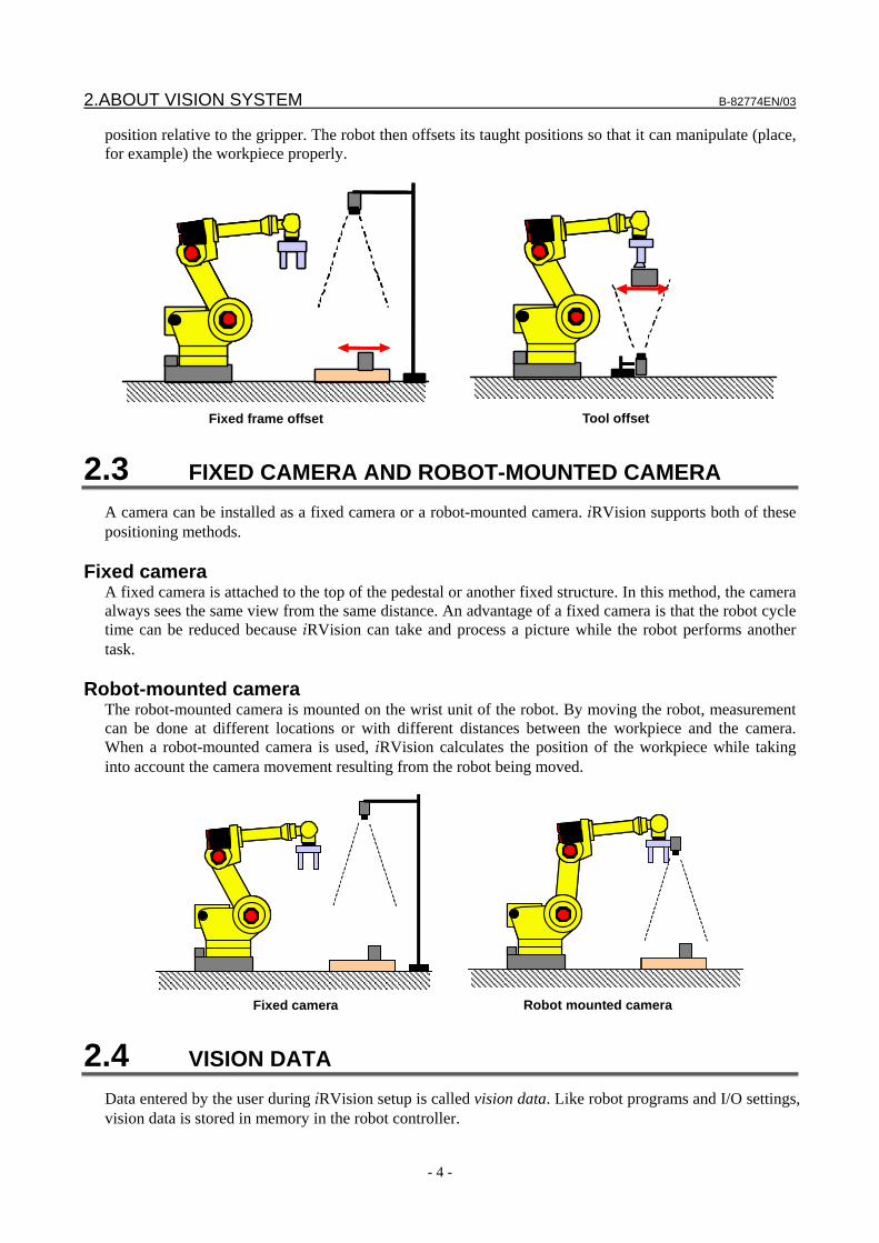
Fixed frame offset With fixed frame offset, the workpiece offset is measured in a coordinate frame fixed with respect to the robot base. A workpiece placed on a fixed surface or a container is viewed by a camera, and the vision system measures its position. The robot then adjusts its taught positions so that it can manipulate (pick up, for example) the workpiece properly.
Tool offset With tool offset, the workpiece offset is measured in a coordinate frame that moves with the robot tool. This method is useful for grippers where the part position in the gripper can vary, such as vacuum grippers. A workpiece held by the robot is viewed by a camera, and the vision system measures its
2.ABOUT VISION SYSTEM B-82774EN/03
- 4 -
position relative to the gripper. The robot then offsets its taught positions so that it can manipulate (place, for example) the workpiece properly.
Fixed frame offset Tool offset
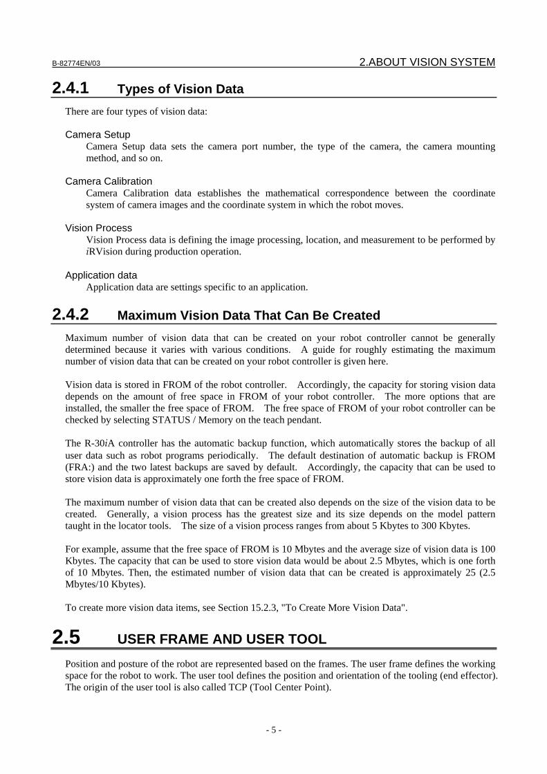
2.3 FIXED CAMERA AND ROBOT-MOUNTED CAMERA A camera can be installed as a fixed camera or a robot-mounted camera. iRVision supports both of these positioning methods.
Fixed camera A fixed camera is attached to the top of the pedestal or another fixed structure. In this method, the camera always sees the same view from the same distance. An advantage of a fixed camera is that the robot cycle time can be reduced because iRVision can take and process a picture while the robot performs another task.
Robot-mounted camera The robot-mounted camera is mounted on the wrist unit of the robot. By moving the robot, measurement can be done at different locations or with different distances between the workpiece and the camera. When a robot-mounted camera is used, iRVision calculates the position of the workpiece while taking into account the camera movement resulting from the robot being moved.
Fixed camera Robot mounted camera
2.4 VISION DATA Data entered by the user during iRVision setup is called vision data. Like robot programs and I/O settings, vision data is stored in memory in the robot controller.
B-82774EN/03 2.ABOUT VISION SYSTEM
- 5 -
2.4.1 Types of Vision Data There are four types of vision data: Camera Setup
Camera Setup data sets the camera port number, the type of the camera, the camera mounting method, and so on.
Camera Calibration
Camera Calibration data establishes the mathematical correspondence between the coordinate system of camera images and the coordinate system in which the robot moves.
Vision Process
Vision Process data is defining the image processing, location, and measurement to be performed by iRVision during production operation.
Application data
Application data are settings specific to an application.
2.4.2 Maximum Vision Data That Can Be Created Maximum number of vision data that can be created on your robot controller cannot be generally determined because it varies with various conditions. A guide for roughly estimating the maximum number of vision data that can be created on your robot controller is given here. Vision data is stored in FROM of the robot controller. Accordingly, the capacity for storing vision data depends on the amount of free space in FROM of your robot controller. The more options that are installed, the smaller the free space of FROM. The free space of FROM of your robot controller can be checked by selecting STATUS / Memory on the teach pendant. The R-30iA controller has the automatic backup function, which automatically stores the backup of all user data such as robot programs periodically. The default destination of automatic backup is FROM (FRA:) and the two latest backups are saved by default. Accordingly, the capacity that can be used to store vision data is approximately one forth the free space of FROM. The maximum number of vision data that can be created also depends on the size of the vision data to be created. Generally, a vision process has the greatest size and its size depends on the model pattern taught in the locator tools. The size of a vision process ranges from about 5 Kbytes to 300 Kbytes. For example, assume that the free space of FROM is 10 Mbytes and the average size of vision data is 100 Kbytes. The capacity that can be used to store vision data would be about 2.5 Mbytes, which is one forth of 10 Mbytes. Then, the estimated number of vision data that can be created is approximately 25 (2.5 Mbytes/10 Kbytes). To create more vision data items, see Section 15.2.3, "To Create More Vision Data".
2.5 USER FRAME AND USER TOOL Position and posture of the robot are represented based on the frames. The user frame defines the working space for the robot to work. The user tool defines the position and orientation of the tooling (end effector). The origin of the user tool is also called TCP (Tool Center Point).
2.ABOUT VISION SYSTEM B-82774EN/03
- 6 -
FANUC robots are teaching-playback robots. Robots of this method play back taught motion only. Therefore, in robot systems that do not use vision, you do not have to use frames because the robots just repeats the taught motion regardless of how accurate the frames are set up. On the other hand, in robot systems that use a vision system, frames are very important. For instance, when the vision system returns the instruction to move 10 mm in X direction or to rotate 30 degrees around the Z-axis, the robot motion completely depends on the accurate definition of the frames.
User Frame The user frame defines the working space in which the robot works. The offset data from the vision system, for instance to move 10 mm in X direction or to rotate 30 degrees around the Z-axis, are all represented based on the user frame. Therefore it is very important to teach the user frame as accurately as possible. If the user frame was set up inaccurately, the robot would move to an incorrect direction or rotate around an incorrect axis. In the case of a 2-dimensional vision application, the user frame covers another important role. It defines the 2-dimensional work plane in the real 3-dimensional space. The 2-D work plane for iRVision must be parallel to the X-Y plane of the user frame. See also the application-specific Operator’s Manual or Setup and Operations Manual for information regarding detailed user frame setup procedures.
NOTE Do not change the posture of the robot while teaching a user frame. If it is
changed, the taught user frame will be less accurate.
User Tool The user tool defines the position and orientation of the robot tooling (end effector). In a robot system that uses vision, it is very important to teach the TCP (Tool Center Point) of the pointer tool that is used during teaching the user frame. If the TCP is less accurate, the taught user frame will also be less accurate. See also the application-specific Operator’s Manual or Setup and Operations Manual for information regarding detailed user tool setup procedures.
Sharing User Frame When two or more robots work together, it is necessary to configure the system so that these robots share physically the same user frame. This is called the sharing of the user frame. Specifically, the sharing of the user frame is needed in the following cases: • Multiple robots are offset with a single set of offset data. • The robot to be offset is different from the robot that has the camera. User frame sharing requires that all robots use the same user frame number. For example, user frame 5 of robot 1 needs to be physically the same as user frame 5 of robot 2.
CAUTION If robots share user frames of different numbers, iRVision cannot offset the
robots correctly. Make sure that the robots share the same user frame number.
B-82774EN/03 3.SETUP
- 7 -
3 SETUP This chapter explains the setup operation that is required before iRVision can be used.
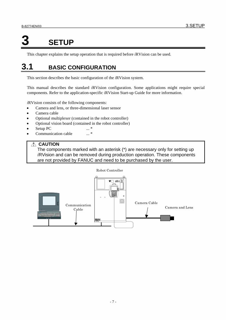
3.1 BASIC CONFIGURATION This section describes the basic configuration of the iRVision system. This manual describes the standard iRVision configuration. Some applications might require special components. Refer to the application-specific iRVision Start-up Guide for more information. iRVision consists of the following components: • Camera and lens, or three-dimensional laser sensor • Camera cable • Optional multiplexer (contained in the robot controller) • Optional vision board (contained in the robot controller) • Setup PC ... * • Communication cable ... *
CAUTION The components marked with an asterisk (*) are necessary only for setting up
iRVision and can be removed during production operation. These components are not provided by FANUC and need to be purchased by the user.
Camera CableCamera and LensCommunication
Cable
Robot Controller
3.SETUP B-82774EN/03
- 8 -
3.2 CONNECTING A CAMERA Connect a camera to the robot controller.
3.2.1 Configuring The Camera Configure the camera for iRVision.
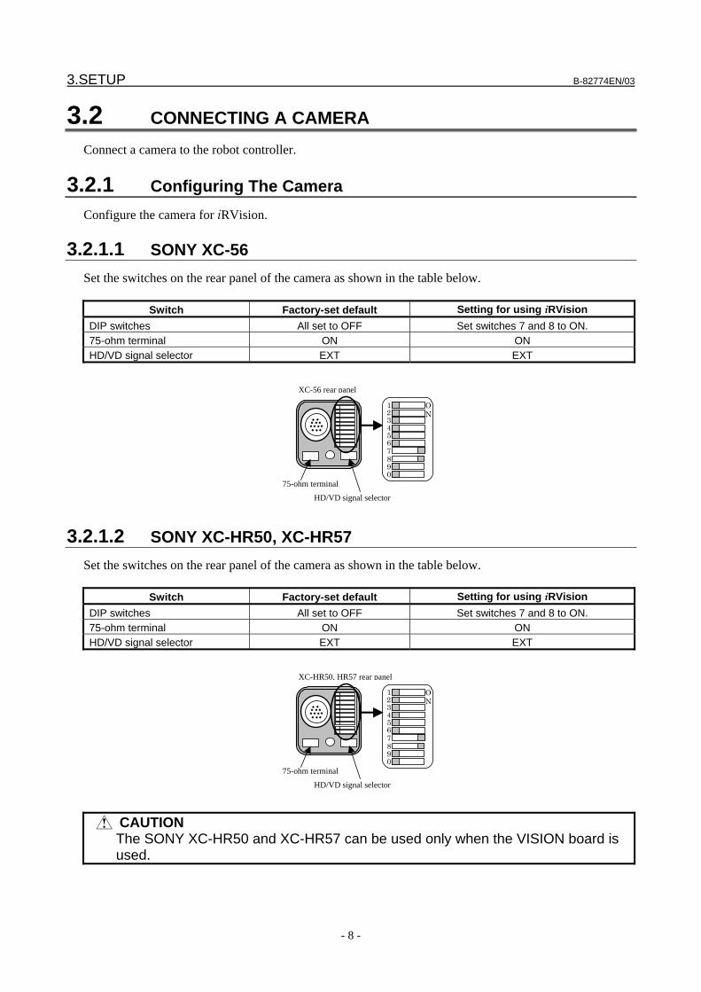
3.2.1.1 SONY XC-56 Set the switches on the rear panel of the camera as shown in the table below.
Switch Factory-set default Setting for using iRVision DIP switches All set to OFF Set switches 7 and 8 to ON. 75-ohm terminal ON ON HD/VD signal selector EXT EXT
075-ohm terminal
HD/VD signal selector
123456789
ON
XC-56 rear panel
3.2.1.2 SONY XC-HR50, XC-HR57 Set the switches on the rear panel of the camera as shown in the table below.
Switch Factory-set default Setting for using iRVision DIP switches All set to OFF Set switches 7 and 8 to ON. 75-ohm terminal ON ON HD/VD signal selector EXT EXT
075-ohm terminal
HD/VD signal selector
123456789
ON
XC-HR50, HR57 rear panel
CAUTION The SONY XC-HR50 and XC-HR57 can be used only when the VISION board is
used.
B-82774EN/03 3.SETUP
- 9 -
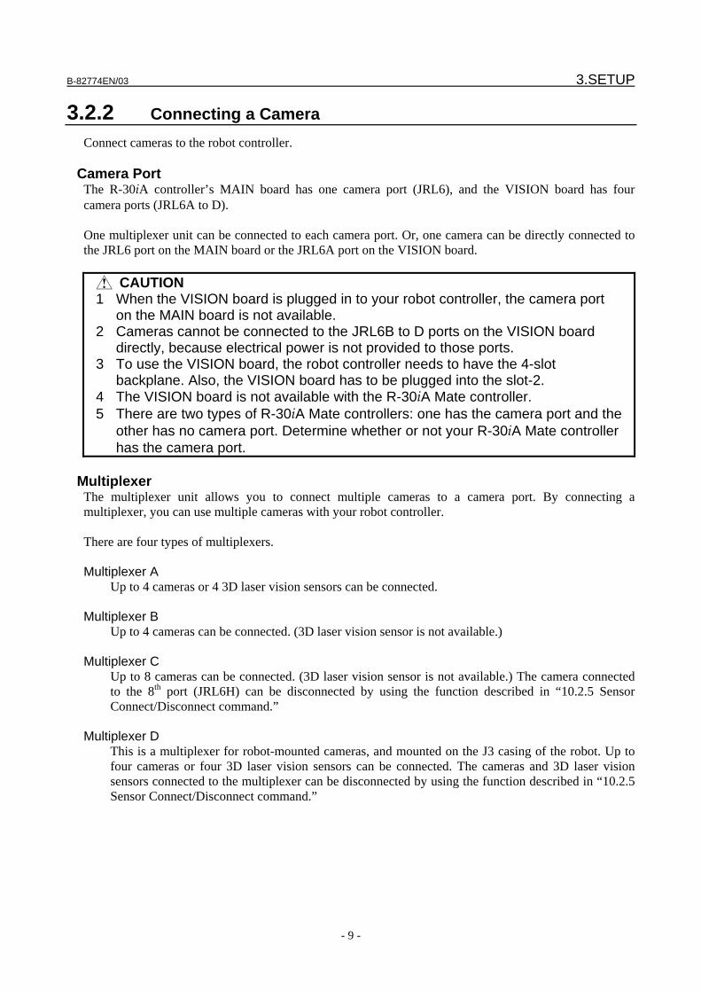
3.2.2 Connecting a Camera Connect cameras to the robot controller.
Camera Port The R-30iA controller’s MAIN board has one camera port (JRL6), and the VISION board has four camera ports (JRL6A to D). One multiplexer unit can be connected to each camera port. Or, one camera can be directly connected to the JRL6 port on the MAIN board or the JRL6A port on the VISION board.
CAUTION 1 When the VISION board is plugged in to your robot controller, the camera port
on the MAIN board is not available. 2 Cameras cannot be connected to the JRL6B to D ports on the VISION board
directly, because electrical power is not provided to those ports. 3 To use the VISION board, the robot controller needs to have the 4-slot
backplane. Also, the VISION board has to be plugged into the slot-2. 4 The VISION board is not available with the R-30iA Mate controller. 5 There are two types of R-30iA Mate controllers: one has the camera port and the
other has no camera port. Determine whether or not your R-30iA Mate controller has the camera port.
Multiplexer
The multiplexer unit allows you to connect multiple cameras to a camera port. By connecting a multiplexer, you can use multiple cameras with your robot controller. There are four types of multiplexers. Multiplexer A
Up to 4 cameras or 4 3D laser vision sensors can be connected. Multiplexer B
Up to 4 cameras can be connected. (3D laser vision sensor is not available.) Multiplexer C
Up to 8 cameras can be connected. (3D laser vision sensor is not available.) The camera connected to the 8th port (JRL6H) can be disconnected by using the function described in “10.2.5 Sensor Connect/Disconnect command.”
Multiplexer D This is a multiplexer for robot-mounted cameras, and mounted on the J3 casing of the robot. Up to
four cameras or four 3D laser vision sensors can be connected. The cameras and 3D laser vision sensors connected to the multiplexer can be disconnected by using the function described in “10.2.5 Sensor Connect/Disconnect command.”

3.SETUP B-82774EN/03
- 10 -
CAUTION 1 To use the 3D laser vision sensor, the multiplexer A or D unit is needed even for
a single sensor. 2 The multiplexer B, C and D units cannot be connected to the VISION board at
the same time. 3 Two or more multiplexer B units cannot be connected to the VISION board at the
same time. 4 Two or more multiplexer D units cannot be connected to the VISION board at the
same time.
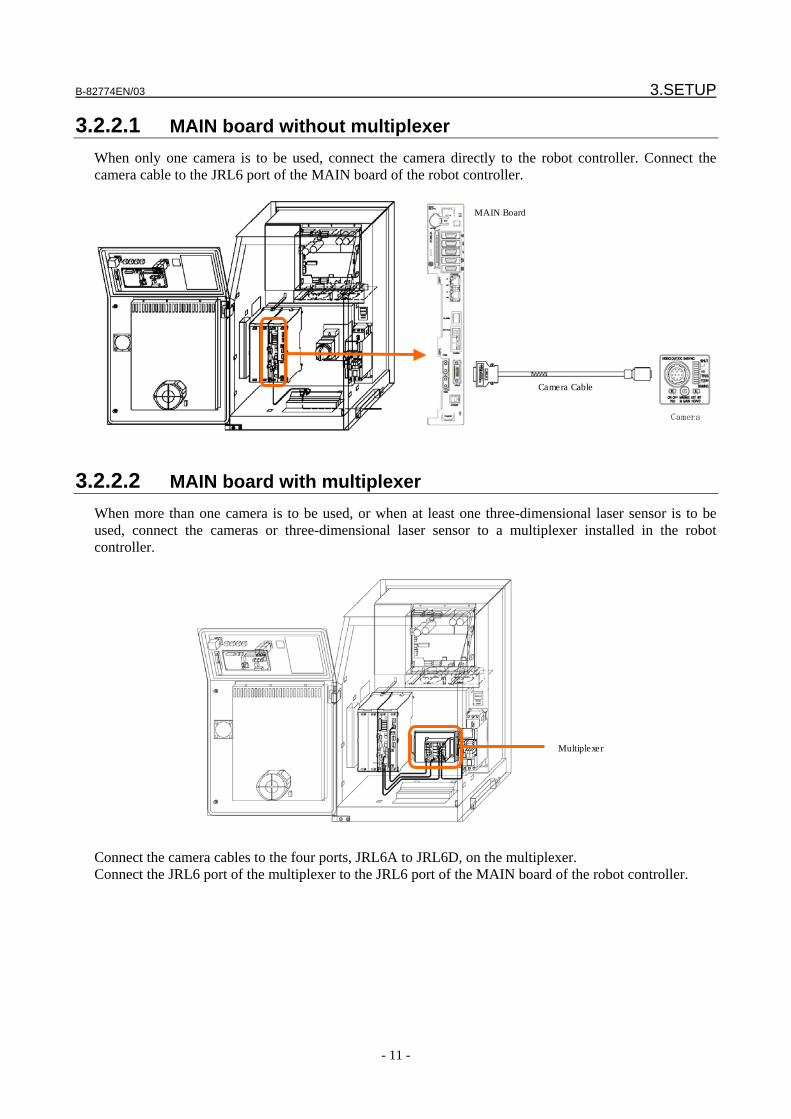
B-82774EN/03 3.SETUP
- 11 -
3.2.2.1 MAIN board without multiplexer When only one camera is to be used, connect the camera directly to the robot controller. Connect the camera cable to the JRL6 port of the MAIN board of the robot controller.
MAIN Board
Camera
Camera Cable
3.2.2.2 MAIN board with multiplexer When more than one camera is to be used, or when at least one three-dimensional laser sensor is to be used, connect the cameras or three-dimensional laser sensor to a multiplexer installed in the robot controller.
Multiplexer
Connect the camera cables to the four ports, JRL6A to JRL6D, on the multiplexer. Connect the JRL6 port of the multiplexer to the JRL6 port of the MAIN board of the robot controller.
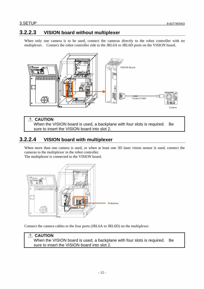
3.SETUP B-82774EN/03
- 12 -
3.2.2.3 VISION board without multiplexer When only one camera is to be used, connect the cameras directly to the robot controller with no multiplexer. Connect the robot controller side to the JRL6A to JRL6D ports on the VISION board.
VISION Board
Camera
Camera Cable
CAUTION When the VISION board is used, a backplane with four slots is required. Be
sure to insert the VISION board into slot 2.
3.2.2.4 VISION board with multiplexer When more than one camera is used, or when at least one 3D laser vision sensor is used, connect the cameras to the multiplexer in the robot controller. The multiplexer is connected to the VISION board.
Multiplexer
Connect the camera cables to the four ports (JRL6A to JRL6D) on the multiplexer.
CAUTION When the VISION board is used, a backplane with four slots is required. Be
sure to insert the VISION board into slot 2.

B-82774EN/03 3.SETUP
- 13 -
3.3 CONNECTING A SETUP PC Connect a PC to the robot controller and prepare to set up the iRVision system. The PC is used only for teaching iRVision and can be disconnected during production operation.
3.3.1 Setup PC A PC is used to set up iRVision. After the setup operation for iRVision is completed, the PC can be removed. Make sure that the setup PC meets the specifications shown below. OS Microsoft® Windows XP Professional Edition Japanese or US version
Microsoft® Windows XP Home Edition Japanese or US version Microsoft® Windows Vista ™ Business Japanese or US version
Web browser Microsoft® Internet Explorer Version 6.0 Microsoft® Internet Explorer Version 7.0
Communication port Ethernet 10BASE-T/100BASE-T
CAUTION 1 The following versions of Windows are not supported:
Microsoft® Windows NT Microsoft® Windows 2000 Microsoft® Windows XP Starter Edition Microsoft® Windows Vista™ Starter Microsoft® Windows Vista™ Home Basic Microsoft® Windows Vista™ Home Premius Microsoft® Windows Vista™ Enterprise Microsoft® Windows Vista™ Ultimate.
2 Microsoft® Internet Explorer 5 and earlier versions are not supported. 3 Microsoft® Internet Explorer 7 can be used for V7.30P and later versions of
robot controllers. It is not supported by V7.20P and earlier versions of robot controllers.
3.3.2 Communication Cable A cable is used to connect the robot controller and the PC to set up iRVision. Choose a 10BASE-T or 100BASE-T cable that meets the specifications shown below. Cable Twisted pair Shield Shielded Cable connection Cross cable (when connecting the PC directly to the robot controller)
Straight cable (when connecting the PC to the robot controller via a hub unit)
3.3.3 Connecting a Communication Cable Connect the robot controller and the PC using an Ethernet cable. On the robot controller side, plug the cable into the Ethernet connector on the front of the MAIN board. On the PC side, plug the cable into the network connector, usually marked .
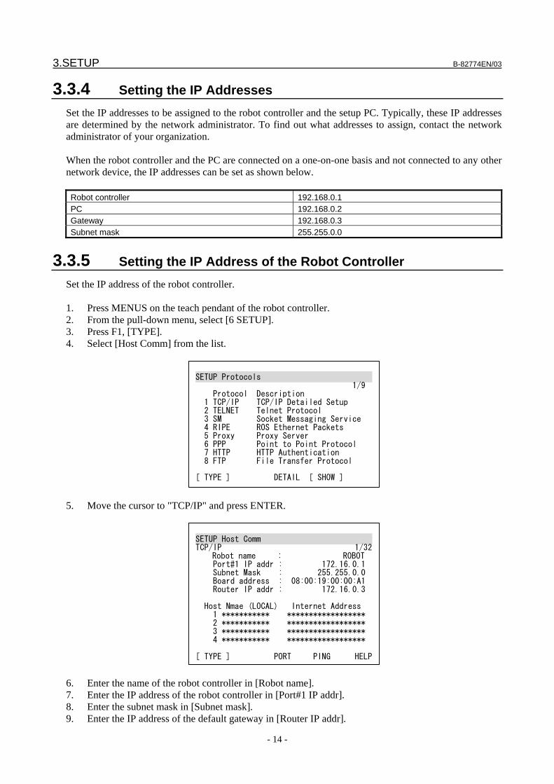
3.SETUP B-82774EN/03
- 14 -
3.3.4 Setting the IP Addresses Set the IP addresses to be assigned to the robot controller and the setup PC. Typically, these IP addresses are determined by the network administrator. To find out what addresses to assign, contact the network administrator of your organization. When the robot controller and the PC are connected on a one-on-one basis and not connected to any other network device, the IP addresses can be set as shown below. Robot controller 192.168.0.1 PC 192.168.0.2 Gateway 192.168.0.3 Subnet mask 255.255.0.0
3.3.5 Setting the IP Address of the Robot Controller Set the IP address of the robot controller. 1. Press MENUS on the teach pendant of the robot controller. 2. From the pull-down menu, select [6 SETUP]. 3. Press F1, [TYPE]. 4. Select [Host Comm] from the list.
SETUP Protocols 1/9 Protocol Description 1 TCP/IP TCP/IP Detailed Setup 2 TELNET Telnet Protocol 3 SM Socket Messaging Service 4 RIPE ROS Ethernet Packets 5 Proxy Proxy Server 6 PPP Point to Point Protocol 7 HTTP HTTP Authentication 8 FTP File Transfer Protocol [ TYPE ] DETAIL [ SHOW ]
5. Move the cursor to "TCP/IP" and press ENTER.
SETUP Host Comm TCP/IP 1/32
Robot name : ROBOT Port#1 IP addr : 172.16.0.1 Subnet Mask : 255.255.0.0 Board address : 08:00:19:00:00:A1 Router IP addr : 172.16.0.3 Host Nmae (LOCAL) Internet Address 1 *********** ****************** 2 *********** ****************** 3 *********** ****************** 4 *********** ****************** [ TYPE ] PORT PING HELP
6. Enter the name of the robot controller in [Robot name]. 7. Enter the IP address of the robot controller in [Port#1 IP addr]. 8. Enter the subnet mask in [Subnet mask]. 9. Enter the IP address of the default gateway in [Router IP addr].
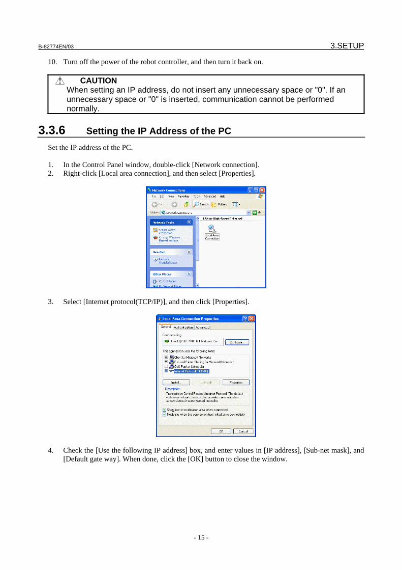
B-82774EN/03 3.SETUP
- 15 -
10. Turn off the power of the robot controller, and then turn it back on.
CAUTION When setting an IP address, do not insert any unnecessary space or "0". If an
unnecessary space or "0" is inserted, communication cannot be performed normally.
3.3.6 Setting the IP Address of the PC Set the IP address of the PC. 1. In the Control Panel window, double-click [Network connection]. 2. Right-click [Local area connection], and then select [Properties].
3. Select [Internet protocol(TCP/IP)], and then click [Properties].
4. Check the [Use the following IP address] box, and enter values in [IP address], [Sub-net mask], and
[Default gate way]. When done, click the [OK] button to close the window.
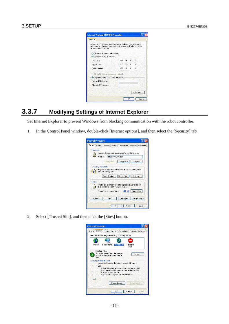
3.SETUP B-82774EN/03
- 16 -
3.3.7 Modifying Settings of Internet Explorer Set Internet Explorer to prevent Windows from blocking communication with the robot controller. 1. In the Control Panel window, double-click [Internet options], and then select the [Security] tab.
2. Select [Trusted Site], and then click the [Sites] button.
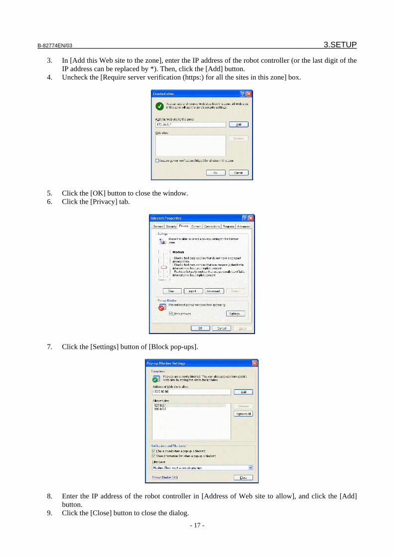
B-82774EN/03 3.SETUP
- 17 -
3. In [Add this Web site to the zone], enter the IP address of the robot controller (or the last digit of the IP address can be replaced by *). Then, click the [Add] button.
4. Uncheck the [Require server verification (https:) for all the sites in this zone] box.
5. Click the [OK] button to close the window. 6. Click the [Privacy] tab.
7. Click the [Settings] button of [Block pop-ups].
8. Enter the IP address of the robot controller in [Address of Web site to allow], and click the [Add]
button. 9. Click the [Close] button to close the dialog.
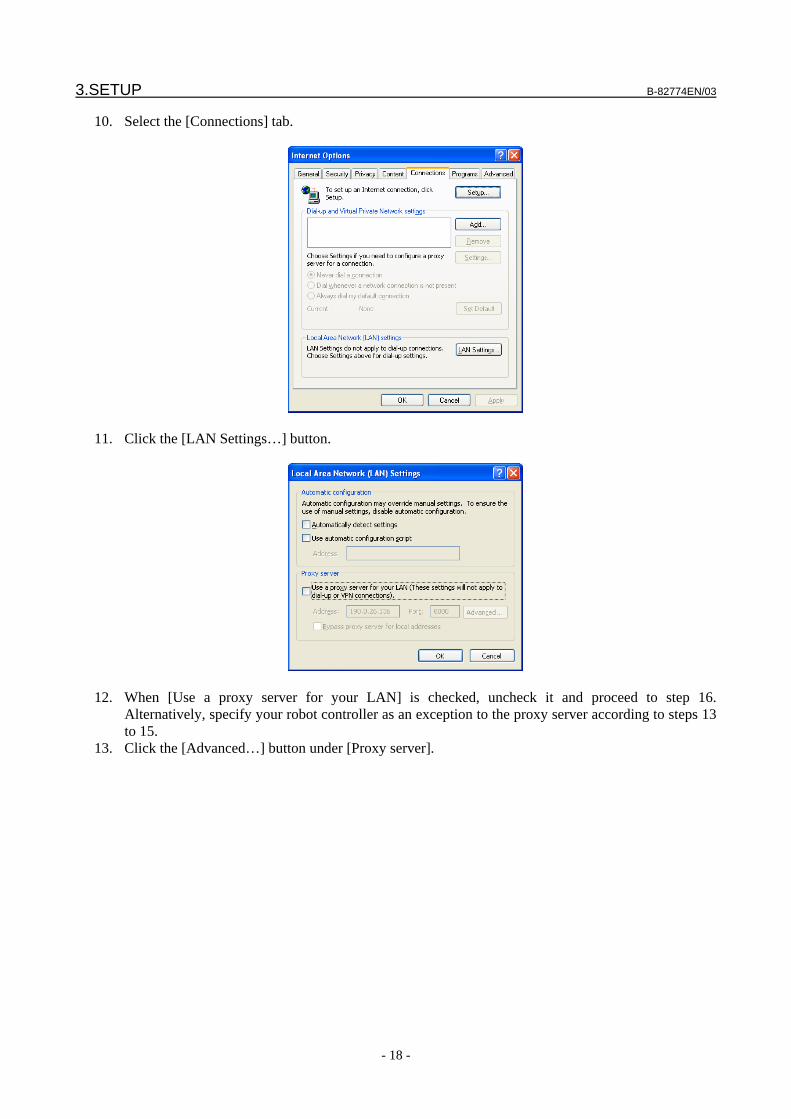
3.SETUP B-82774EN/03
- 18 -
10. Select the [Connections] tab.
11. Click the [LAN Settings…] button.
12. When [Use a proxy server for your LAN] is checked, uncheck it and proceed to step 16.
Alternatively, specify your robot controller as an exception to the proxy server according to steps 13 to 15.
13. Click the [Advanced…] button under [Proxy server].
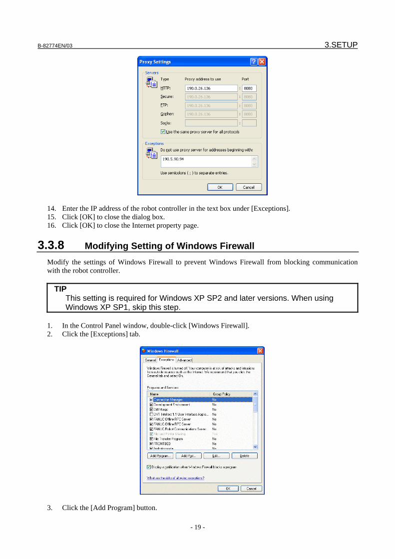
B-82774EN/03 3.SETUP
- 19 -
14. Enter the IP address of the robot controller in the text box under [Exceptions]. 15. Click [OK] to close the dialog box. 16. Click [OK] to close the Internet property page.
3.3.8 Modifying Setting of Windows Firewall Modify the settings of Windows Firewall to prevent Windows Firewall from blocking communication with the robot controller.
TIP This setting is required for Windows XP SP2 and later versions. When using
Windows XP SP1, skip this step. 1. In the Control Panel window, double-click [Windows Firewall]. 2. Click the [Exceptions] tab.
3. Click the [Add Program] button.
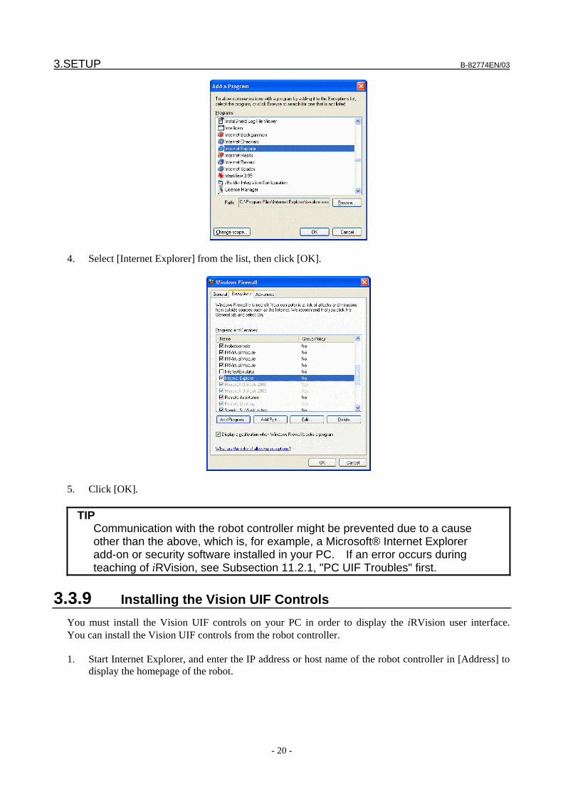
3.SETUP B-82774EN/03
- 20 -
4. Select [Internet Explorer] from the list, then click [OK].
5. Click [OK].
TIP Communication with the robot controller might be prevented due to a cause
other than the above, which is, for example, a Microsoft® Internet Explorer add-on or security software installed in your PC. If an error occurs during teaching of iRVision, see Subsection 11.2.1, "PC UIF Troubles" first.
3.3.9 Installing the Vision UIF Controls You must install the Vision UIF controls on your PC in order to display the iRVision user interface. You can install the Vision UIF controls from the robot controller. 1. Start Internet Explorer, and enter the IP address or host name of the robot controller in [Address] to
display the homepage of the robot.
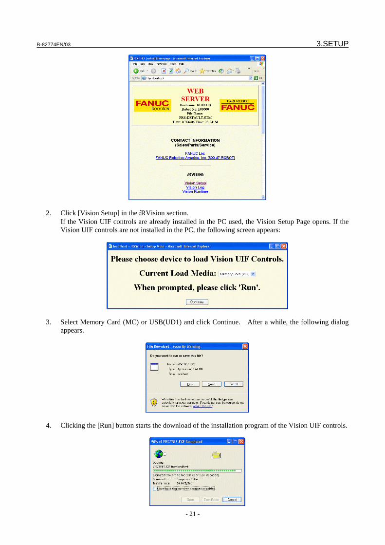
B-82774EN/03 3.SETUP
- 21 -
2. Click [Vision Setup] in the iRVision section.
If the Vision UIF controls are already installed in the PC used, the Vision Setup Page opens. If the Vision UIF controls are not installed in the PC, the following screen appears:
3. Select Memory Card (MC) or USB(UD1) and click Continue. After a while, the following dialog
appears.
4. Clicking the [Run] button starts the download of the installation program of the Vision UIF controls.
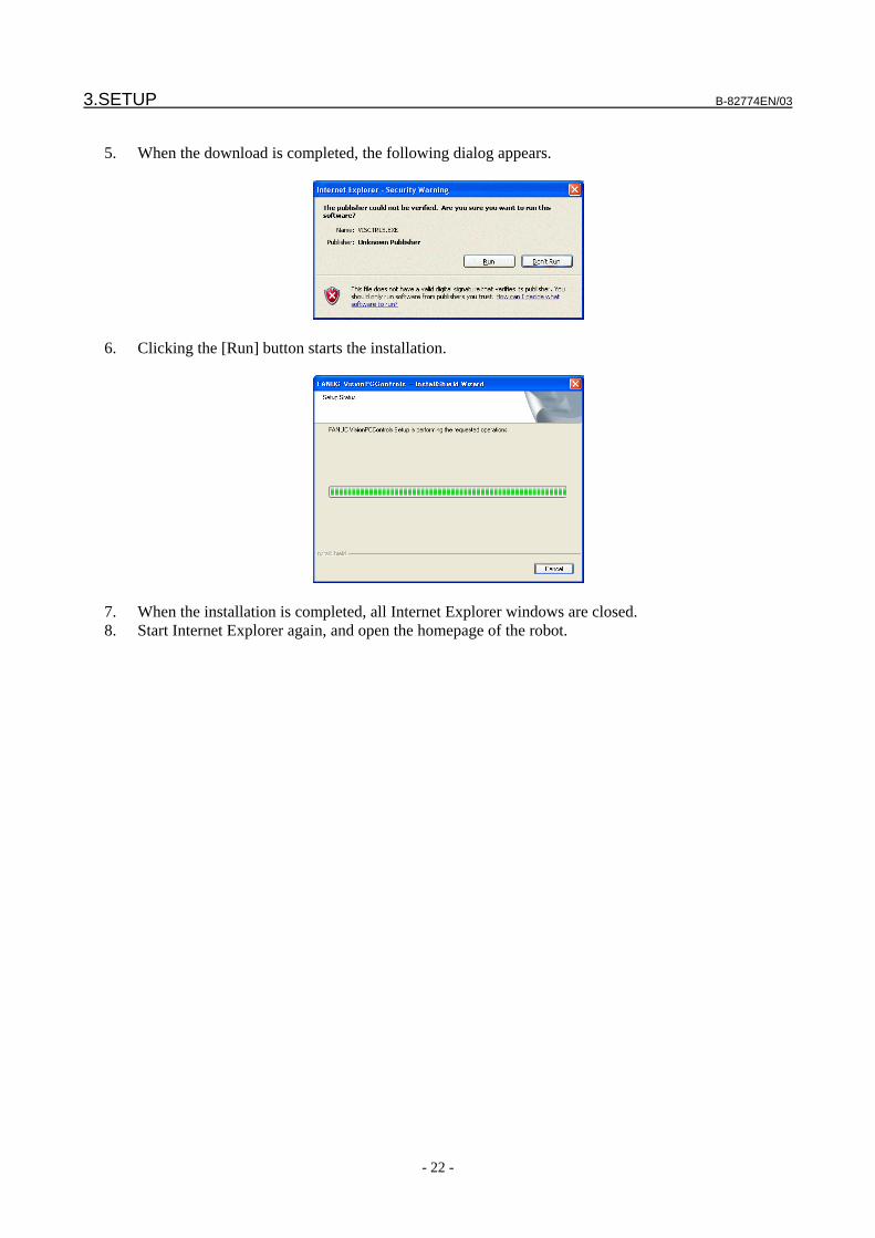
3.SETUP B-82774EN/03
- 22 -
5. When the download is completed, the following dialog appears.
6. Clicking the [Run] button starts the installation.
7. When the installation is completed, all Internet Explorer windows are closed. 8. Start Internet Explorer again, and open the homepage of the robot.
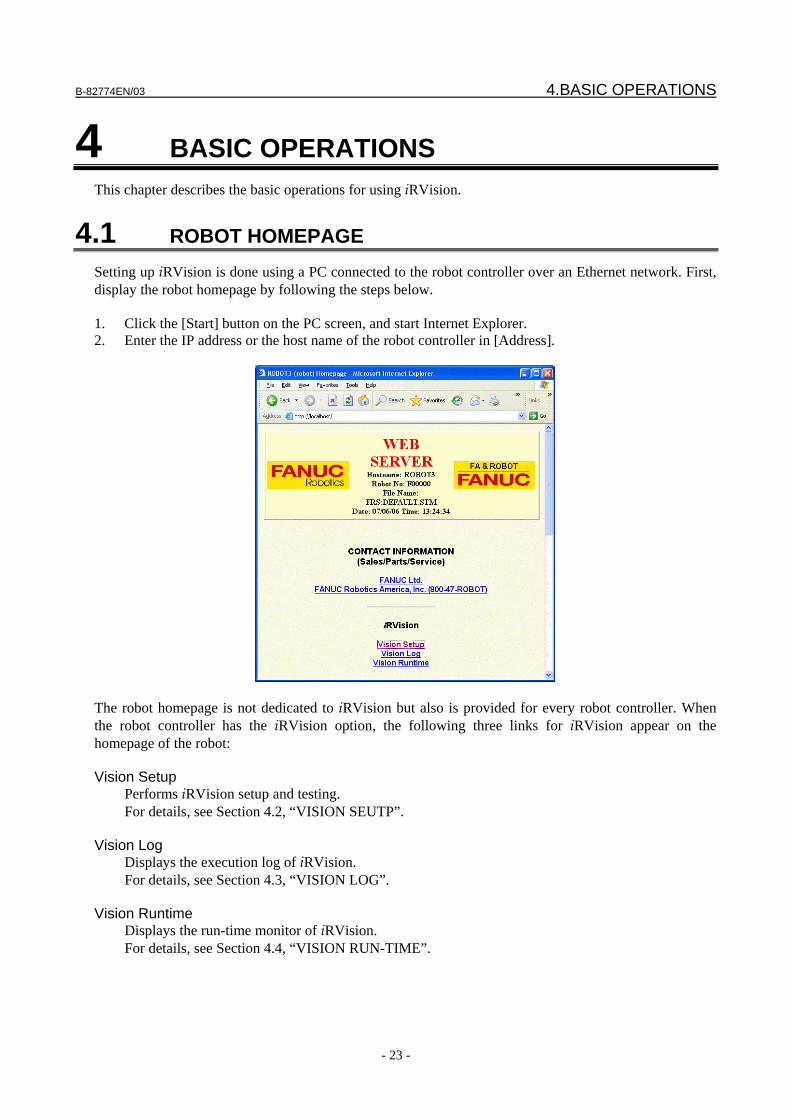
B-82774EN/03 4.BASIC OPERATIONS
- 23 -
4 BASIC OPERATIONS This chapter describes the basic operations for using iRVision.
4.1 ROBOT HOMEPAGE Setting up iRVision is done using a PC connected to the robot controller over an Ethernet network. First, display the robot homepage by following the steps below. 1. Click the [Start] button on the PC screen, and start Internet Explorer. 2. Enter the IP address or the host name of the robot controller in [Address].
The robot homepage is not dedicated to iRVision but also is provided for every robot controller. When the robot controller has the iRVision option, the following three links for iRVision appear on the homepage of the robot: Vision Setup
Performs iRVision setup and testing. For details, see Section 4.2, “VISION SEUTP”.
Vision Log
Displays the execution log of iRVision. For details, see Section 4.3, “VISION LOG”.
Vision Runtime
Displays the run-time monitor of iRVision. For details, see Section 4.4, “VISION RUN-TIME”.
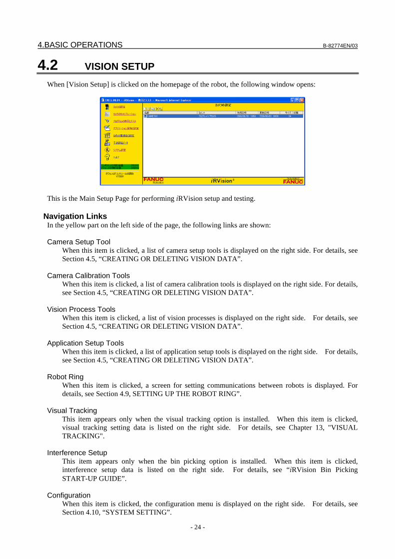
4.BASIC OPERATIONS B-82774EN/03
- 24 -
4.2 VISION SETUP When [Vision Setup] is clicked on the homepage of the robot, the following window opens:
This is the Main Setup Page for performing iRVision setup and testing.
Navigation Links In the yellow part on the left side of the page, the following links are shown: Camera Setup Tool
When this item is clicked, a list of camera setup tools is displayed on the right side. For details, see Section 4.5, “CREATING OR DELETING VISION DATA”.
Camera Calibration Tools
When this item is clicked, a list of camera calibration tools is displayed on the right side. For details, see Section 4.5, “CREATING OR DELETING VISION DATA”.
Vision Process Tools
When this item is clicked, a list of vision processes is displayed on the right side. For details, see Section 4.5, “CREATING OR DELETING VISION DATA”.
Application Setup Tools
When this item is clicked, a list of application setup tools is displayed on the right side. For details, see Section 4.5, “CREATING OR DELETING VISION DATA”.
Robot Ring
When this item is clicked, a screen for setting communications between robots is displayed. For details, see Section 4.9, SETTING UP THE ROBOT RING”.
Visual Tracking This item appears only when the visual tracking option is installed. When this item is clicked,
visual tracking setting data is listed on the right side. For details, see Chapter 13, "VISUAL TRACKING".
Interference Setup This item appears only when the bin picking option is installed. When this item is clicked,
interference setup data is listed on the right side. For details, see “iRVision Bin Picking START-UP GUIDE”.
Configuration
When this item is clicked, the configuration menu is displayed on the right side. For details, see Section 4.10, “SYSTEM SETTING”.
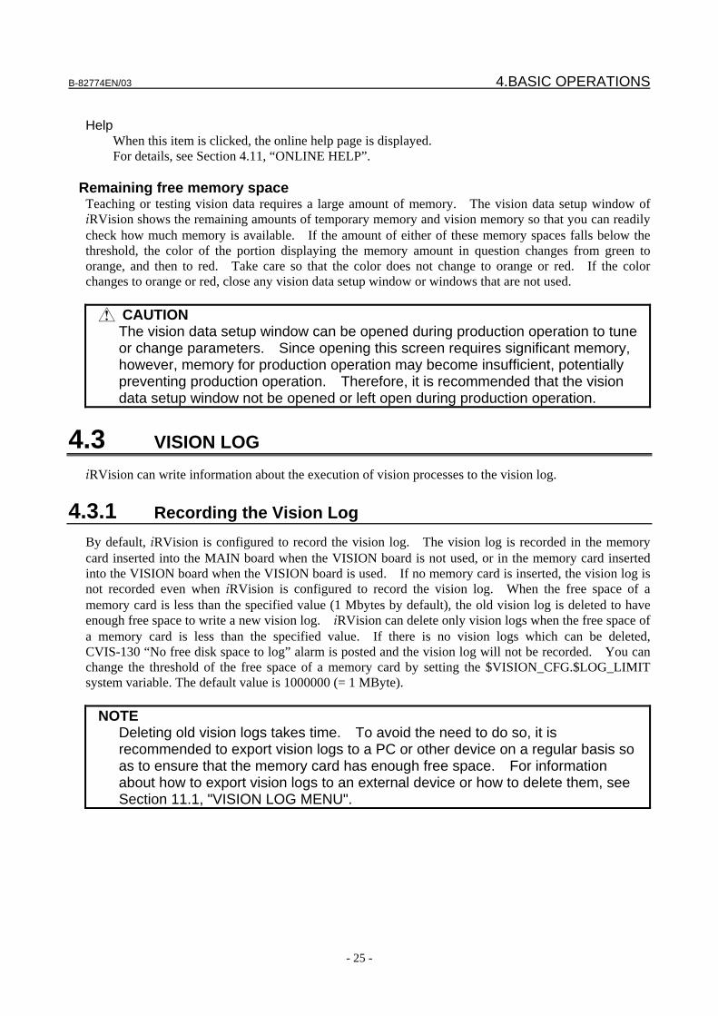
B-82774EN/03 4.BASIC OPERATIONS
- 25 -
Help
When this item is clicked, the online help page is displayed. For details, see Section 4.11, “ONLINE HELP”.
Remaining free memory space
Teaching or testing vision data requires a large amount of memory. The vision data setup window of iRVision shows the remaining amounts of temporary memory and vision memory so that you can readily check how much memory is available. If the amount of either of these memory spaces falls below the threshold, the color of the portion displaying the memory amount in question changes from green to orange, and then to red. Take care so that the color does not change to orange or red. If the color changes to orange or red, close any vision data setup window or windows that are not used.
CAUTION The vision data setup window can be opened during production operation to tune
or change parameters. Since opening this screen requires significant memory, however, memory for production operation may become insufficient, potentially preventing production operation. Therefore, it is recommended that the vision data setup window not be opened or left open during production operation.
4.3 VISION LOG iRVision can write information about the execution of vision processes to the vision log.
4.3.1 Recording the Vision Log By default, iRVision is configured to record the vision log. The vision log is recorded in the memory card inserted into the MAIN board when the VISION board is not used, or in the memory card inserted into the VISION board when the VISION board is used. If no memory card is inserted, the vision log is not recorded even when iRVision is configured to record the vision log. When the free space of a memory card is less than the specified value (1 Mbytes by default), the old vision log is deleted to have enough free space to write a new vision log. iRVision can delete only vision logs when the free space of a memory card is less than the specified value. If there is no vision logs which can be deleted, CVIS-130 “No free disk space to log” alarm is posted and the vision log will not be recorded. You can change the threshold of the free space of a memory card by setting the $VISION_CFG.$LOG_LIMIT system variable. The default value is 1000000 (= 1 MByte).
NOTE Deleting old vision logs takes time. To avoid the need to do so, it is
recommended to export vision logs to a PC or other device on a regular basis so as to ensure that the memory card has enough free space. For information about how to export vision logs to an external device or how to delete them, see Section 11.1, "VISION LOG MENU".
4.BASIC OPERATIONS B-82774EN/03
- 26 -
CAUTION If the free space of a memory card falls below the specified value as a result of
other files being written to the memory card, the vision log function will try to delete vision logs until the free space gets larger than the specified value in the next vision execution. In this case, it may take time before the next vision execution can start. If there is a lot of data to be deleted. For example, storing everything to the memory card could cause such a case. However, it will not cause any problems if there is a backup already written to the memory card and its size is as large as that of new backup.
NOTE If you have vision logs recorded in a memory card with one controller and then
execute a vision process with that memory card inserted into another controller, the vision logs recorded with the original controller may get overwritten.
4.3.2 Disabling the Vision Log To prevent iRVision from writing the vision log even if a memory card is inserted, the vision log can be disabled. Refer to the section 4.10, “SYSTEM SETTING” for details.
4.3.3 Logging Images Images snapped by vision processes can be saved along with the vision log. The logged images that are saved can be used for future troubleshooting, as well as when performing a test run of a vision process. For information about how to run a test using logged images, see Subsection 4.12.12, "Image Playback". Images are saved as a part of the vision log on a memory card. Whether to save images to the vision log is specified for each vision process. In the Setup Window for a vision process, select one of the following: Don’t Log
Do not save any images to the vision log. Log Failed Images
Save images only when the vision operation fails. Log All Images
Save all images. When the vision log is disabled, images are not logged even if you set up the vision processes to log images.
CAUTION If you choose to save logged images, it can take much longer to record the
vision log. Only when [Log All Images] is necessary for a troubleshooting or other reason, select this item. Normally, select [Don't Log] or [Log Failed Images]. How much longer the recording of the vision log takes depends on the type of vision process; see the section pertaining to the vision process concerned. The speed of the memory card is also a factor. Insert a high-speed memory card for applications where speed is crucial.
B-82774EN/03 4.BASIC OPERATIONS
- 27 -
NOTE If you have the vision log disabled in the system variable, logged images are not
saved even when you set the vision process to save logged images.
4.3.4 Viewing the Vision Log The vision log can be viewed on the setup PC. 1. Start Internet Explorer, and display the robot homepage.
2. Click [Vision Log] in the iRVision section.
3. From the [Select Log Date] drop-down list in the upper right part of the window, select the date of
the log you want to view. If you want to view the vision logs of all available dates, select [All Dates].
4. From the [Select Data] drop-down list in the upper right part of the window, select the data name of the vision process whose log you want to view. If you want to view the vision logs of all existing vision processes, select [All Data]. Note that, if you select [All Dates] in [Select Log Date], [All Data] is not available.

4.BASIC OPERATIONS B-82774EN/03
- 28 -
5. The vision log of the selected vision process recorded on the selected date is displayed on the right side of the window.
6. Click a line in the list on the right side of the window. 7. The list in the lower part of the window displays the detailed results of the selected execution. If
any image has been saved during that execution, the saved image is displayed in the upper left part.
4.3.5 File Configuration of the Vision Log By default, the vision log is recorded in the folder MC:/VISION/LOG/. A sub-folder is created for each day under the folder and the vision log and images for the day are saved in the created sub-folder. For example, MC:/VISION/LOG/Y08APR10/ is the sub-folder for April 10, 2008. Under the sub-folder for each day, two types of files are saved; .VL and .PNG. .VL Logged data file .PNG Logged image file
CAUTION If the file name, the folder name or the folder structure was changed, the
correspondence between the logged data and logged image becomes incorrect, and eventually the file cannot be utilized. Therefore, do not change the folder structure and file name when you copy them to another device.
4.4 VISION RUN-TIME Execution of a vision process can be monitored on the PC or iPendant during production operation.
4.4.1 Monitoring on the PC 1. Start Internet Explorer, and display the robot homepage.
2. Click [Vision Run-Time] in the iRVision section.
B-82774EN/03 4.BASIC OPERATIONS
- 29 -
4.4.2 Monitoring on the iPendant 1. Press MENUS on the iPendant. 2. Select [4 STATUS], and then [VISION]. 3. The iPendant displays a runtime monitor screen similar to that on the PC.
4.5 CREATING OR DELETING VISION DATA You can create, delete, copy, or rename vision data in the vision data list.
4.BASIC OPERATIONS B-82774EN/03
- 30 -
Information displayed in the vision data list The vision data list shows the following items: Name
The name of vision data is displayed. A name of up to 34 alphanumeric or one-byte katakana characters can be set.
Comment Any character string is indicated to provide additional information about vision data. A comment
consisting of up to 30 one-byte or 15 two-byte characters can be set. Created The time and date at which corresponding vision data was created for the first time is indicated. Modified The time and date at which corresponding vision data was modified last is indicated. Size The size of a vision data file in bytes is indicated. Open Normally this field is left blank. When the Setup Window for vision data is opened, [Window] is
indicated in this field.
TIP If the network is disconnected during setup of vision data, setup can be resumed
as long as the controller is not turned off. Redisplay the iRVision setup page on the PC to continue editing the vision data.
4.5.1 Creating New Vision Data To create new vision data, perform the following steps. 1. Click the button.
2. In [Type], select the type of the vision data you are going to create. 3. In [Name], enter the name of the vision data you are going to create. The name can be up to 34
alphanumeric characters in length. 4. Click [OK].
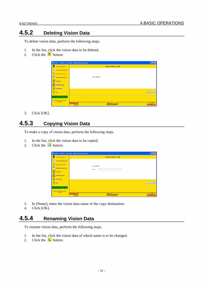
B-82774EN/03 4.BASIC OPERATIONS
- 31 -
4.5.2 Deleting Vision Data To delete vision data, perform the following steps. 1. In the list, click the vision data to be deleted. 2. Click the button.
3. Click [OK].
4.5.3 Copying Vision Data To make a copy of vision data, perform the following steps. 1. In the list, click the vision data to be copied. 2. Click the button.
3. In [Name], enter the vision data name of the copy destination. 4. Click [OK].
4.5.4 Renaming Vision Data To rename vision data, perform the following steps. 1. In the list, click the vision data of which name is to be changed. 2. Click the button.
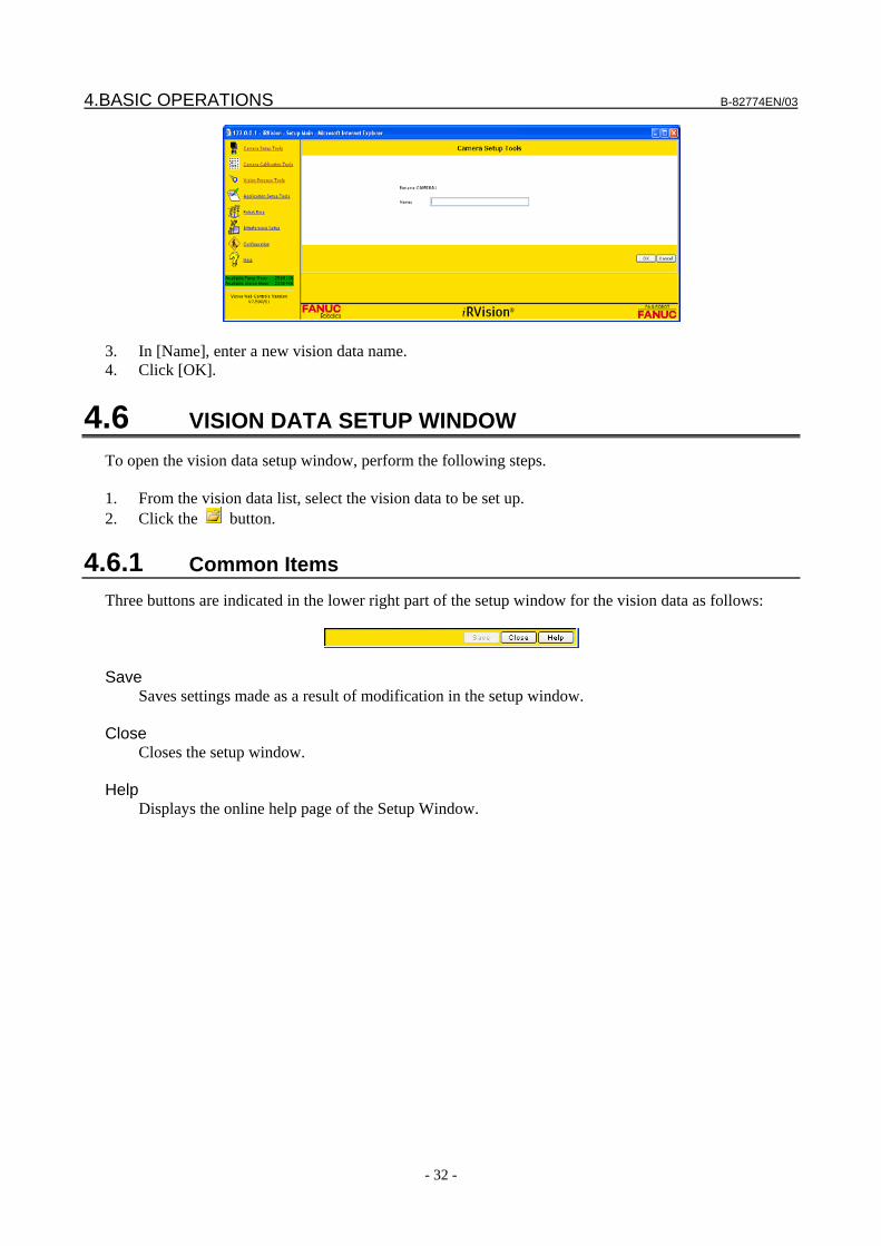
4.BASIC OPERATIONS B-82774EN/03
- 32 -
3. In [Name], enter a new vision data name. 4. Click [OK].
4.6 VISION DATA SETUP WINDOW To open the vision data setup window, perform the following steps. 1. From the vision data list, select the vision data to be set up. 2. Click the button.
4.6.1 Common Items Three buttons are indicated in the lower right part of the setup window for the vision data as follows:
Save
Saves settings made as a result of modification in the setup window. Close Closes the setup window. Help
Displays the online help page of the Setup Window.

B-82774EN/03 4.BASIC OPERATIONS
- 33 -
CAUTION 1 The new settings made by modifying the contents of the vision data Setup
Window are not saved until the [Save] button is clicked. If the window for the vision data is closed without performing the save operation, the new settings made by modification will be lost.
2 The maximum number of vision data setup windows that you can open at the same time is limited to 5. If you try to open the 6th setup window, an alarm message is displayed, and the window is not opened. And, when there is not enough memory on the controller, the new window cannot be opened even if the number of open windows is less than 5. In such cases, close one or more of the other windows first, and then open the new window.
3 The vision data setup window can be opened during production operation to tune or change parameters. Since opening setup windows requires significant memory, the memory for production operation might become insufficient, potentially preventing production operation. Therefore, it is recommended that the vision data setup windows not be opened or left open during production operation.
TIP To restore the original data after making modifications to the contents of the
Setup Window, close the window by clicking the [Close] button without clicking the [Save] button.
4.6.2 Camera Setup Window The setup window for a camera setup tool has the following structure:
A This area is an image display control that shows an image from the camera. For information on how
to use this control, see Subsection 4.12.4, “Image Display Control”. B Setting items for the camera setup tool. The setting items vary depending on the type of camera
setup tool. See Chapter 5, “CAMERA SETUP”.
4.6.3 Camera Calibration Setup Window The setup window for the camera calibration tool has the following structure:
A B
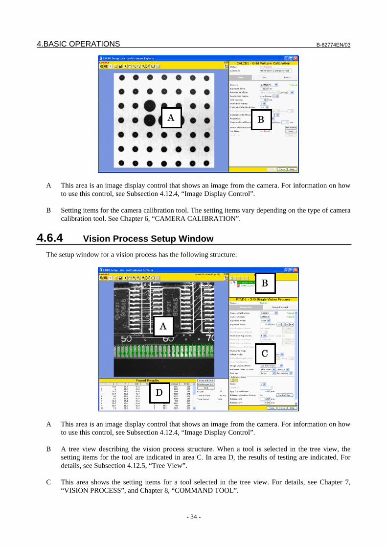
4.BASIC OPERATIONS B-82774EN/03
- 34 -
A This area is an image display control that shows an image from the camera. For information on how
to use this control, see Subsection 4.12.4, “Image Display Control”. B Setting items for the camera calibration tool. The setting items vary depending on the type of camera
calibration tool. See Chapter 6, “CAMERA CALIBRATION”.
4.6.4 Vision Process Setup Window The setup window for a vision process has the following structure:
A This area is an image display control that shows an image from the camera. For information on how
to use this control, see Subsection 4.12.4, “Image Display Control”. B A tree view describing the vision process structure. When a tool is selected in the tree view, the
setting items for the tool are indicated in area C. In area D, the results of testing are indicated. For details, see Subsection 4.12.5, “Tree View”.
C This area shows the setting items for a tool selected in the tree view. For details, see Chapter 7,
“VISION PROCESS”, and Chapter 8, “COMMAND TOOL”.
A
C
B
D
A B
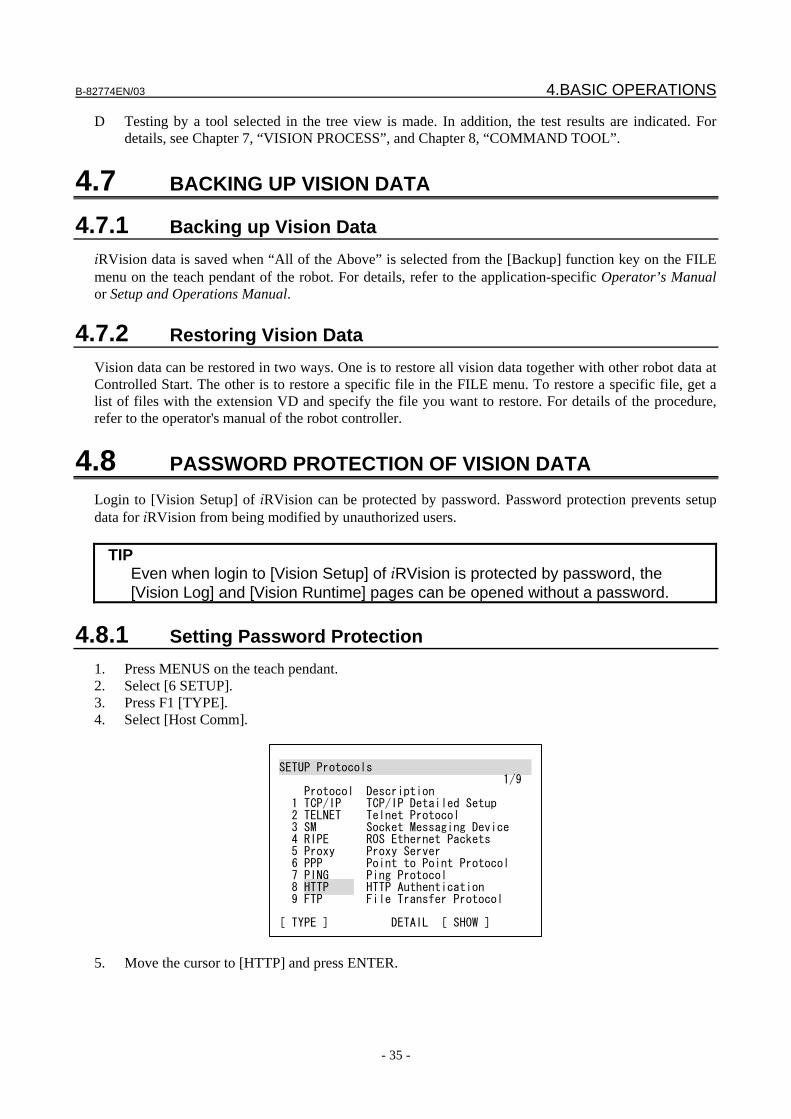
B-82774EN/03 4.BASIC OPERATIONS
- 35 -
D Testing by a tool selected in the tree view is made. In addition, the test results are indicated. For details, see Chapter 7, “VISION PROCESS”, and Chapter 8, “COMMAND TOOL”.
4.7 BACKING UP VISION DATA
4.7.1 Backing up Vision Data iRVision data is saved when “All of the Above” is selected from the [Backup] function key on the FILE menu on the teach pendant of the robot. For details, refer to the application-specific Operator’s Manual or Setup and Operations Manual.
4.7.2 Restoring Vision Data Vision data can be restored in two ways. One is to restore all vision data together with other robot data at Controlled Start. The other is to restore a specific file in the FILE menu. To restore a specific file, get a list of files with the extension VD and specify the file you want to restore. For details of the procedure, refer to the operator's manual of the robot controller.
4.8 PASSWORD PROTECTION OF VISION DATA Login to [Vision Setup] of iRVision can be protected by password. Password protection prevents setup data for iRVision from being modified by unauthorized users.
TIP Even when login to [Vision Setup] of iRVision is protected by password, the
[Vision Log] and [Vision Runtime] pages can be opened without a password.
4.8.1 Setting Password Protection 1. Press MENUS on the teach pendant. 2. Select [6 SETUP]. 3. Press F1 [TYPE]. 4. Select [Host Comm].
SETUP Protocols 1/9 Protocol Description 1 TCP/IP TCP/IP Detailed Setup 2 TELNET Telnet Protocol 3 SM Socket Messaging Device 4 RIPE ROS Ethernet Packets 5 Proxy Proxy Server 6 PPP Point to Point Protocol 7 PING Ping Protocol 8 HTTP HTTP Authentication 9 FTP File Transfer Protocol [ TYPE ] DETAIL [ SHOW ]
5. Move the cursor to [HTTP] and press ENTER.
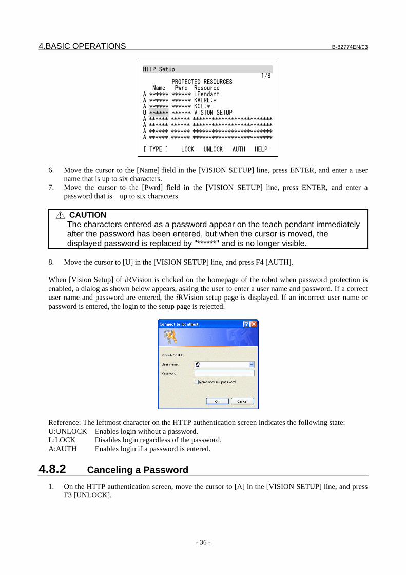
4.BASIC OPERATIONS B-82774EN/03
- 36 -
HTTP Setup 1/8 PROTECTED RESOURCES Name Pwrd Resource A ****** ****** iPendant A ****** ****** KALRE:* A ****** ****** KCL:* U ****** ****** VISION SETUP A ****** ****** *************************A ****** ****** *************************A ****** ****** *************************A ****** ****** ************************* [ TYPE ] LOCK UNLOCK AUTH HELP
6. Move the cursor to the [Name] field in the [VISION SETUP] line, press ENTER, and enter a user
name that is up to six characters. 7. Move the cursor to the [Pwrd] field in the [VISION SETUP] line, press ENTER, and enter a
password that is up to six characters.
CAUTION The characters entered as a password appear on the teach pendant immediately
after the password has been entered, but when the cursor is moved, the displayed password is replaced by "******" and is no longer visible.
8. Move the cursor to [U] in the [VISION SETUP] line, and press F4 [AUTH]. When [Vision Setup] of iRVision is clicked on the homepage of the robot when password protection is enabled, a dialog as shown below appears, asking the user to enter a user name and password. If a correct user name and password are entered, the iRVision setup page is displayed. If an incorrect user name or password is entered, the login to the setup page is rejected.
Reference: The leftmost character on the HTTP authentication screen indicates the following state: U:UNLOCK Enables login without a password. L:LOCK Disables login regardless of the password. A:AUTH Enables login if a password is entered.
4.8.2 Canceling a Password 1. On the HTTP authentication screen, move the cursor to [A] in the [VISION SETUP] line, and press
F3 [UNLOCK].

B-82774EN/03 4.BASIC OPERATIONS
- 37 -
4.9 SETTING UP THE ROBOT RING In iRVision, when a camera is mounted on another robot, or when the target workpiece for tool offset operation is gripped by another robot, inter-robot communication is performed to acquire information about the robot position. Robot ring is the function for inter-robot communication via Ethernet. Although the robot ring is not a function of iRVision, iRVision provides the setup page to setup the robot ring easily.
Setting Up The Robot Ring 1. On the robot homepage, click [Vision Setup] of iRVision. 2. Click [Robot Ring]. A robot list is displayed on the right side.
3. Click the button.
4. Enter the name of the robot in [Name]. 5. Enter the IP address of the robot in [IP address]. 6. Click [OK]. A robot list is re-displayed.
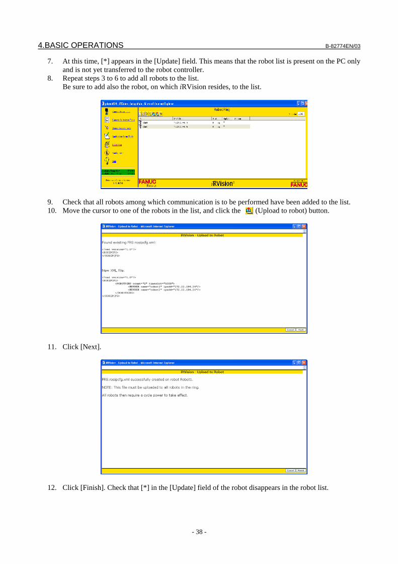
4.BASIC OPERATIONS B-82774EN/03
- 38 -
7. At this time, [*] appears in the [Update] field. This means that the robot list is present on the PC only and is not yet transferred to the robot controller.
8. Repeat steps 3 to 6 to add all robots to the list. Be sure to add also the robot, on which iRVision resides, to the list.
9. Check that all robots among which communication is to be performed have been added to the list. 10. Move the cursor to one of the robots in the list, and click the (Upload to robot) button.
11. Click [Next].
12. Click [Finish]. Check that [*] in the [Update] field of the robot disappears in the robot list.
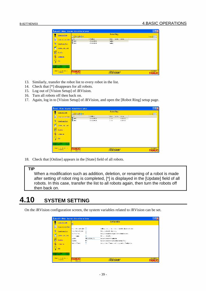
B-82774EN/03 4.BASIC OPERATIONS
- 39 -
13. Similarly, transfer the robot list to every robot in the list. 14. Check that [*] disappears for all robots. 15. Log out of [Vision Setup] of iRVision. 16. Turn all robots off then back on. 17. Again, log in to [Vision Setup] of iRVision, and open the [Robot Ring] setup page.
18. Check that [Online] appears in the [State] field of all robots.
TIP When a modification such as addition, deletion, or renaming of a robot is made
after setting of robot ring is completed, [*] is displayed in the [Update] field of all robots. In this case, transfer the list to all robots again, then turn the robots off then back on.
4.10 SYSTEM SETTING On the iRVision configuration screen, the system variables related to iRVision can be set.
4.BASIC OPERATIONS B-82774EN/03
- 40 -
Advanced Runtime Display When this item is checked, an image on the runtime monitor can be enlarged or scrolled. However, it takes more time to update the screen of the runtime monitor. By default, it is not checked.
Disable Runtime Display When this item is checked, the system does not perform any processing related to the runtime monitor and the runtime monitor does not display any information. Network traffic as well as the time required for vision processing is reduced. By default, it is not checked.
Decimal Comma When this item is checked, a comma (,) is used in place of a period (.) as a decimal point. This item is provided for use in Europe. By default, it is not checked.
Disable Logging When this item is checked, the system does not perform any processing related to saving of the vision log or logged images. The time required for vision processing is reduced. By default, it is not checked.
Log Path This item is used to specify the destination folder of the vision log or logged images. The default value is MC:/VISION/LOG for MAIN board, or MCV:/VISION/LOG for VISION board.
Data Path This item is used to specify the destination folder of vision data. This folder is read-only and cannot be changed.
Position Difference Normally, iRVision displays the found position on the runtime display. When this item is checked, iRVision displays the position difference, instead of the found position. Note that the position difference that is displayed on the runtime display is different from the offset stored in the vision register. The offset value stored in the vision register is mathematically correct data intended to be used to actually offset the robot motion but is difficult for the human operator to understand at a glance. The position difference value displayed on the runtime display is processed data that is made easy for the human operator to comprehend. It allows the amount of offset of the target object to be grasped more intuitively.
CAUTION If you perform robot position offset by writing the position difference value
displayed on the runtime display to the vision register or position register, the robot position will not be offset correctly.
4.11 ONLINE HELP When the iRVision online help option is ordered, the iRVision online help can be viewed from the setup PC. To open the iRVision online help, use one of the following methods.
4.11.1 Displaying the Online Help from the Main Setup Page On the main setup page of iRVision, a link to [Help] is provided on the left side of the page as follows:
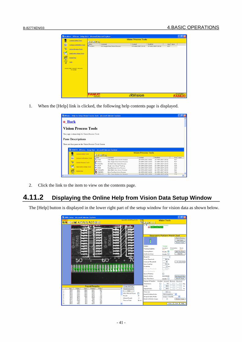
B-82774EN/03 4.BASIC OPERATIONS
- 41 -
1. When the [Help] link is clicked, the following help contents page is displayed.
2. Click the link to the item to view on the contents page.
4.11.2 Displaying the Online Help from Vision Data Setup Window The [Help] button is displayed in the lower right part of the setup window for vision data as shown below.
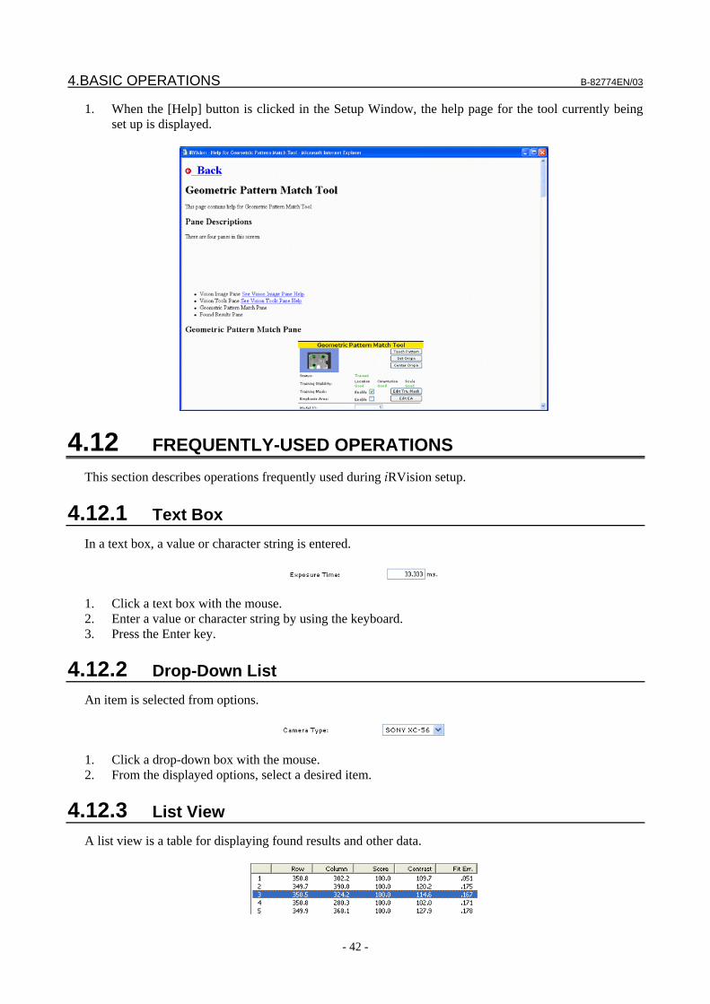
4.BASIC OPERATIONS B-82774EN/03
- 42 -
1. When the [Help] button is clicked in the Setup Window, the help page for the tool currently being set up is displayed.
4.12 FREQUENTLY-USED OPERATIONS This section describes operations frequently used during iRVision setup.
4.12.1 Text Box In a text box, a value or character string is entered.
1. Click a text box with the mouse. 2. Enter a value or character string by using the keyboard. 3. Press the Enter key.
4.12.2 Drop-Down List An item is selected from options.
1. Click a drop-down box with the mouse. 2. From the displayed options, select a desired item.
4.12.3 List View A list view is a table for displaying found results and other data.
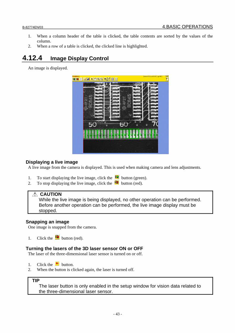
B-82774EN/03 4.BASIC OPERATIONS
- 43 -
1. When a column header of the table is clicked, the table contents are sorted by the values of the column.
2. When a row of a table is clicked, the clicked line is highlighted.
4.12.4 Image Display Control An image is displayed.
Displaying a live image A live image from the camera is displayed. This is used when making camera and lens adjustments. 1. To start displaying the live image, click the button (green). 2. To stop displaying the live image, click the button (red).
CAUTION While the live image is being displayed, no other operation can be performed.
Before another operation can be performed, the live image display must be stopped.
Snapping an image
One image is snapped from the camera. 1. Click the button (red).
Turning the lasers of the 3D laser sensor ON or OFF The laser of the three-dimensional laser sensor is turned on or off. 1. Click the button. 2. When the button is clicked again, the laser is turned off.
TIP The laser button is only enabled in the setup window for vision data related to
the three-dimensional laser sensor.
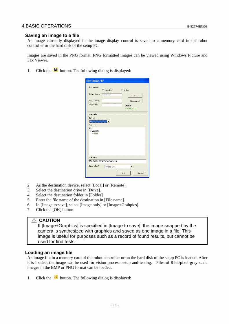
4.BASIC OPERATIONS B-82774EN/03
- 44 -
Saving an image to a file An image currently displayed in the image display control is saved to a memory card in the robot controller or the hard disk of the setup PC. Images are saved in the PNG format. PNG formatted images can be viewed using Windows Picture and Fax Viewer. 1. Click the button. The following dialog is displayed:
2 As the destination device, select [Local] or [Remote]. 3. Select the destination drive in [Drive]. 4. Select the destination folder in [Folder]. 5. Enter the file name of the destination in [File name]. 6. In [Image to save], select [Image only] or [Image+Grahpics]. 7. Click the [OK] button.
CAUTION If [Image+Graphics] is specified in [Image to save], the image snapped by the
camera is synthesized with graphics and saved as one image in a file. This image is useful for purposes such as a record of found results, but cannot be used for find tests.
Loading an image file
An image file in a memory card of the robot controller or on the hard disk of the setup PC is loaded. After it is loaded, the image can be used for vision process setup and testing. Files of 8-bit/pixel gray-scale images in the BMP or PNG format can be loaded. 1. Click the button. The following dialog is displayed:
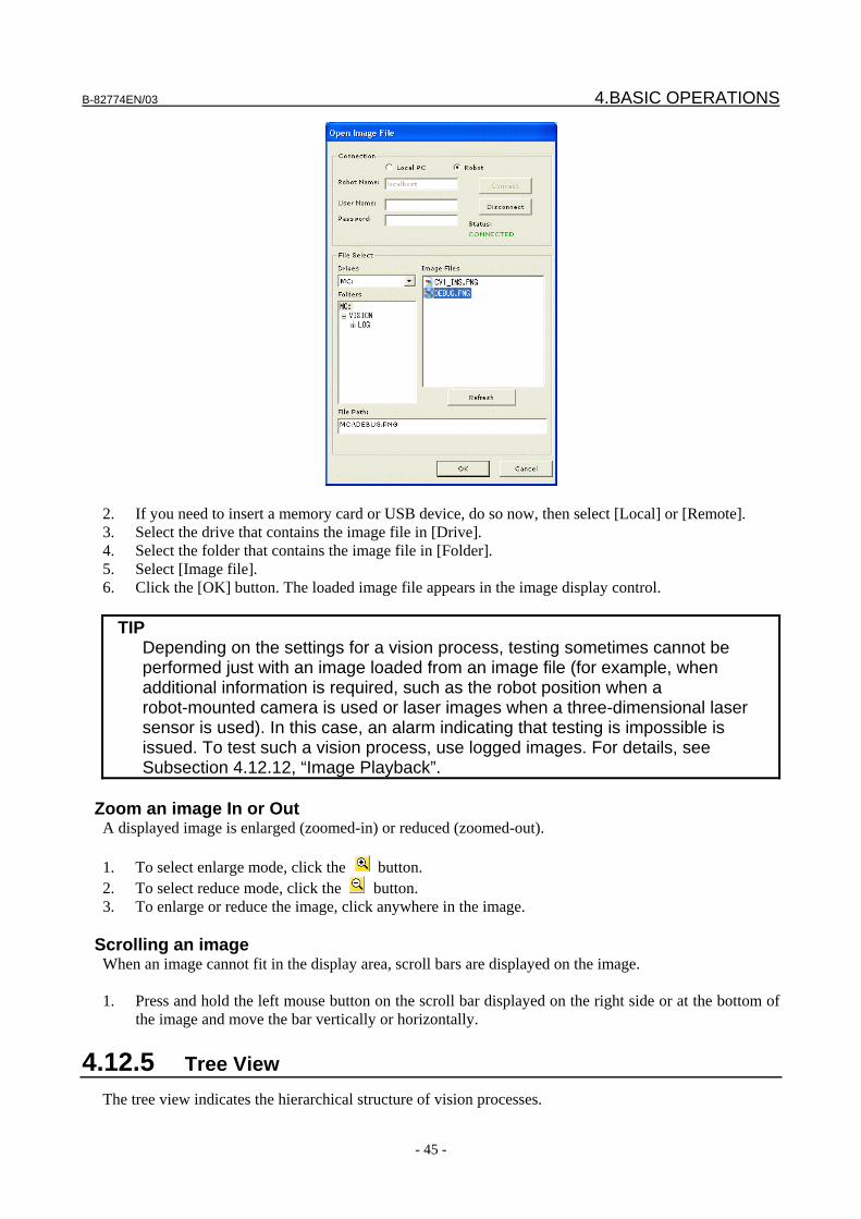
B-82774EN/03 4.BASIC OPERATIONS
- 45 -
2. If you need to insert a memory card or USB device, do so now, then select [Local] or [Remote]. 3. Select the drive that contains the image file in [Drive]. 4. Select the folder that contains the image file in [Folder]. 5. Select [Image file]. 6. Click the [OK] button. The loaded image file appears in the image display control.
TIP Depending on the settings for a vision process, testing sometimes cannot be
performed just with an image loaded from an image file (for example, when additional information is required, such as the robot position when a robot-mounted camera is used or laser images when a three-dimensional laser sensor is used). In this case, an alarm indicating that testing is impossible is issued. To test such a vision process, use logged images. For details, see Subsection 4.12.12, “Image Playback”.
Zoom an image In or Out
A displayed image is enlarged (zoomed-in) or reduced (zoomed-out). 1. To select enlarge mode, click the button. 2. To select reduce mode, click the button. 3. To enlarge or reduce the image, click anywhere in the image.
Scrolling an image When an image cannot fit in the display area, scroll bars are displayed on the image. 1. Press and hold the left mouse button on the scroll bar displayed on the right side or at the bottom of
the image and move the bar vertically or horizontally.
4.12.5 Tree View The tree view indicates the hierarchical structure of vision processes.

4.BASIC OPERATIONS B-82774EN/03
- 46 -
In the above figure, for example, the 2D single-view vision process includes two GPM locator tools. Under the GPM Locator Tool 1, one histogram tool and one conditional execution tool is present. Elements that make up a vision process, such as the GPM locator tools, histogram tool, and conditional execution tool are called command tools. When a vision process is executed, its command tools are executed sequentially from the top, and finally the vision process calculates offset data. The measurement window of a command tool such as the Histogram 1 that is placed under the GPM Locator Tool 1 is shifted and rotated dynamically according to the position of the found workpiece by the GPM Locator Tool 1. One of the tools displayed in the tree view is always highlighted. It is the tool currently selected in the setup window, and setting and testing can be performed for this tool. The color of each tool displayed in the tree view indicates the setup status of the tool. When a tool is displayed in green, setup is already completed for the tool. When a tool is displayed in red, at least one item remains that needs to be set up for that tool. When all tools of a vision process are displayed in green, the vision process is regarded as having been completely set up.
Selecting a tool Select the tool to be set up. 1. Click the icon of a tool in the tree view. 2. The clicked tool is highlighted, and the corresponding setting page and test page are displayed.
Adding a tool A new command tool is added to a vision process. 1. Select a parent tool (one level higher) under which a new tool is to be inserted. 2. Click the button.
3. In [Type], select the type of the command tool to be inserted. 4. In [Name], enter the name of the command tool to be inserted. 5. Click [OK].
Deleting a tool A command tool is deleted from a vision process.
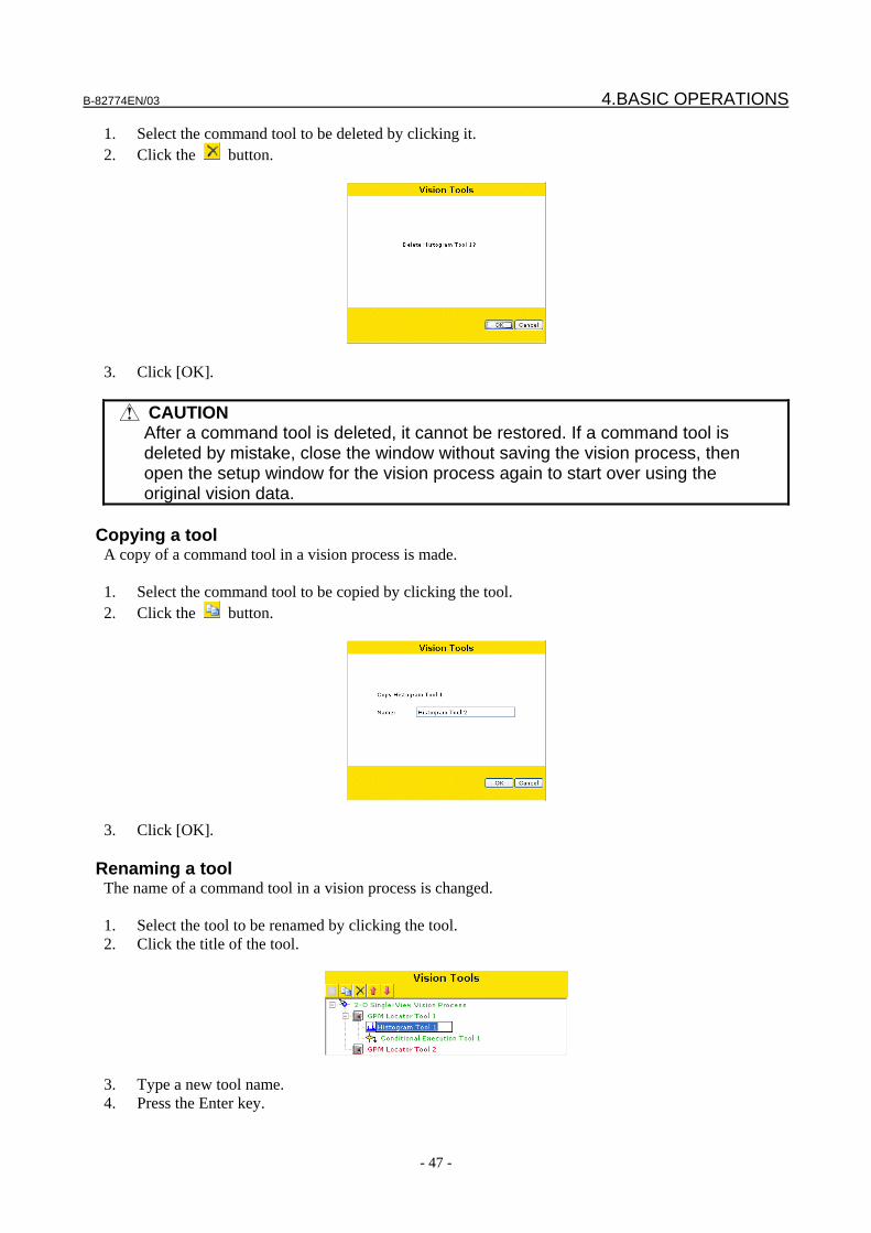
B-82774EN/03 4.BASIC OPERATIONS
- 47 -
1. Select the command tool to be deleted by clicking it. 2. Click the button.
3. Click [OK].
CAUTION After a command tool is deleted, it cannot be restored. If a command tool is
deleted by mistake, close the window without saving the vision process, then open the setup window for the vision process again to start over using the original vision data.
Copying a tool
A copy of a command tool in a vision process is made. 1. Select the command tool to be copied by clicking the tool. 2. Click the button.
3. Click [OK].
Renaming a tool The name of a command tool in a vision process is changed. 1. Select the tool to be renamed by clicking the tool. 2. Click the title of the tool.
3. Type a new tool name. 4. Press the Enter key.
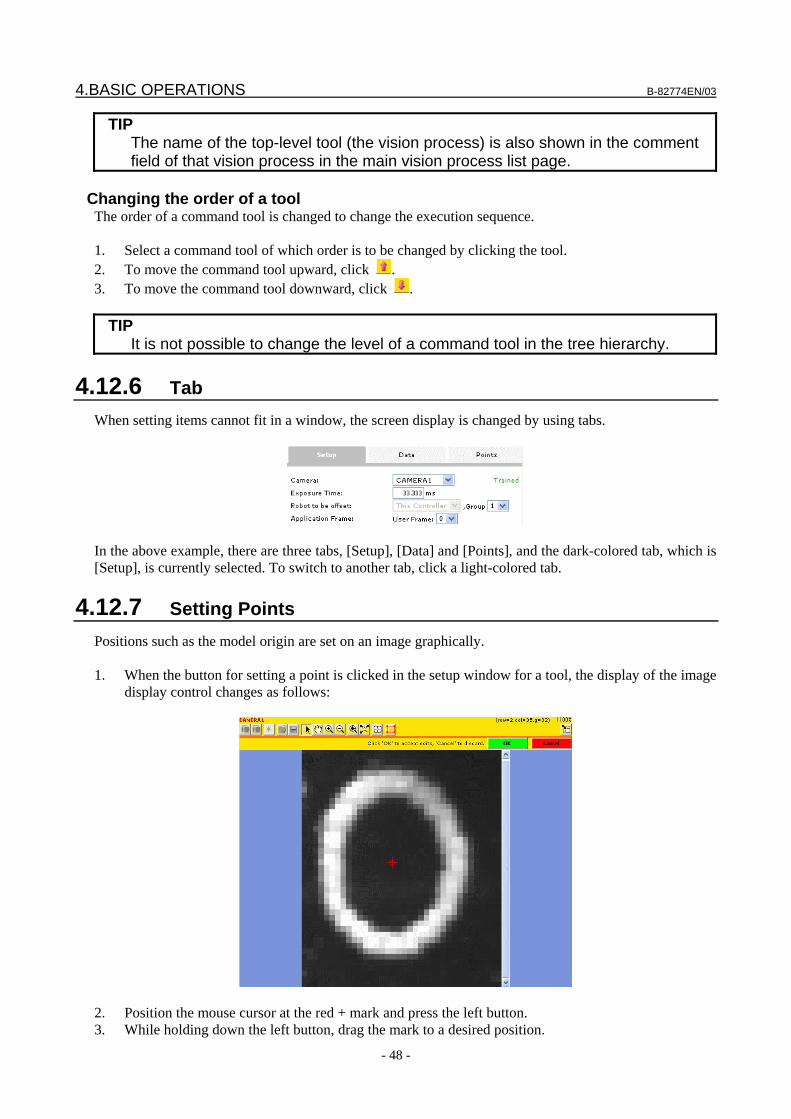
4.BASIC OPERATIONS B-82774EN/03
- 48 -
TIP The name of the top-level tool (the vision process) is also shown in the comment
field of that vision process in the main vision process list page.
Changing the order of a tool The order of a command tool is changed to change the execution sequence. 1. Select a command tool of which order is to be changed by clicking the tool. 2. To move the command tool upward, click . 3. To move the command tool downward, click .
TIP It is not possible to change the level of a command tool in the tree hierarchy.
4.12.6 Tab When setting items cannot fit in a window, the screen display is changed by using tabs.
In the above example, there are three tabs, [Setup], [Data] and [Points], and the dark-colored tab, which is [Setup], is currently selected. To switch to another tab, click a light-colored tab.
4.12.7 Setting Points Positions such as the model origin are set on an image graphically. 1. When the button for setting a point is clicked in the setup window for a tool, the display of the image
display control changes as follows:
2. Position the mouse cursor at the red + mark and press the left button. 3. While holding down the left button, drag the mark to a desired position.
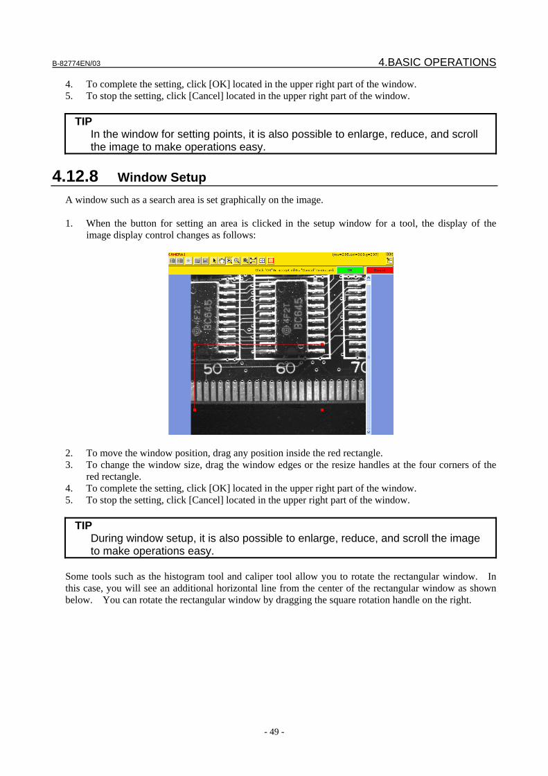
B-82774EN/03 4.BASIC OPERATIONS
- 49 -
4. To complete the setting, click [OK] located in the upper right part of the window. 5. To stop the setting, click [Cancel] located in the upper right part of the window.
TIP In the window for setting points, it is also possible to enlarge, reduce, and scroll
the image to make operations easy.
4.12.8 Window Setup A window such as a search area is set graphically on the image. 1. When the button for setting an area is clicked in the setup window for a tool, the display of the
image display control changes as follows:
2. To move the window position, drag any position inside the red rectangle. 3. To change the window size, drag the window edges or the resize handles at the four corners of the
red rectangle. 4. To complete the setting, click [OK] located in the upper right part of the window. 5. To stop the setting, click [Cancel] located in the upper right part of the window.
TIP During window setup, it is also possible to enlarge, reduce, and scroll the image
to make operations easy. Some tools such as the histogram tool and caliper tool allow you to rotate the rectangular window. In this case, you will see an additional horizontal line from the center of the rectangular window as shown below. You can rotate the rectangular window by dragging the square rotation handle on the right.
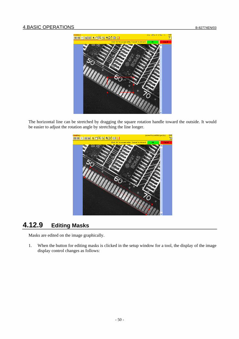
4.BASIC OPERATIONS B-82774EN/03
- 50 -
The horizontal line can be stretched by dragging the square rotation handle toward the outside. It would be easier to adjust the rotation angle by stretching the line longer.
4.12.9 Editing Masks Masks are edited on the image graphically. 1. When the button for editing masks is clicked in the setup window for a tool, the display of the image
display control changes as follows:
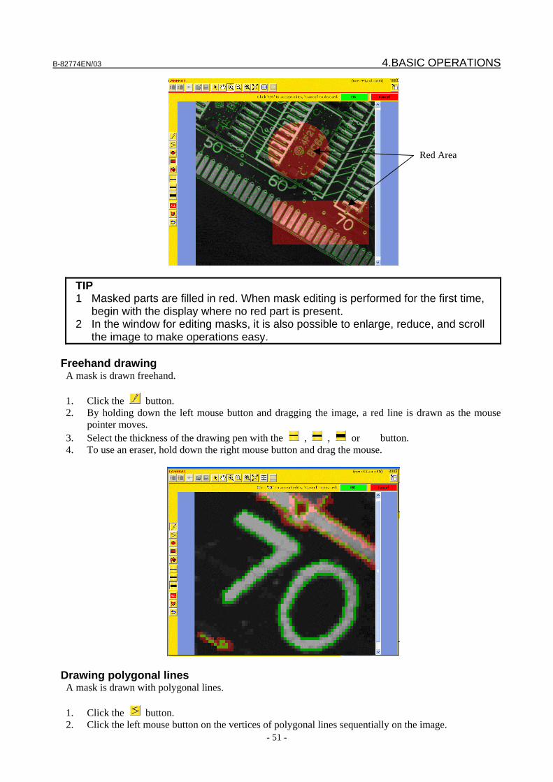
B-82774EN/03 4.BASIC OPERATIONS
- 51 -
TIP 1 Masked parts are filled in red. When mask editing is performed for the first time,
begin with the display where no red part is present. 2 In the window for editing masks, it is also possible to enlarge, reduce, and scroll
the image to make operations easy.
Freehand drawing A mask is drawn freehand. 1. Click the button. 2. By holding down the left mouse button and dragging the image, a red line is drawn as the mouse
pointer moves. 3. Select the thickness of the drawing pen with the , , or button. 4. To use an eraser, hold down the right mouse button and drag the mouse.
Drawing polygonal lines A mask is drawn with polygonal lines. 1. Click the button. 2. Click the left mouse button on the vertices of polygonal lines sequentially on the image.
Red Area
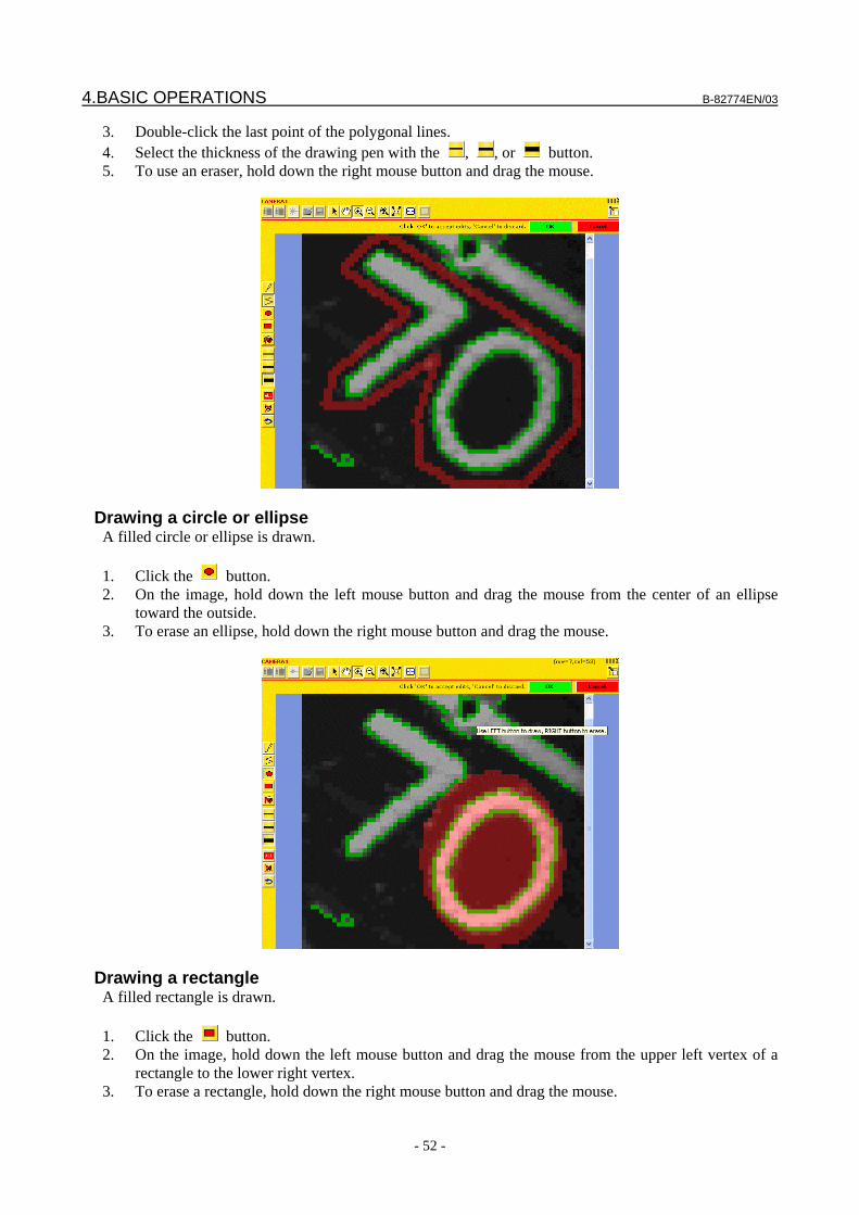
4.BASIC OPERATIONS B-82774EN/03
- 52 -
3. Double-click the last point of the polygonal lines. 4. Select the thickness of the drawing pen with the , , or button. 5. To use an eraser, hold down the right mouse button and drag the mouse.
Drawing a circle or ellipse A filled circle or ellipse is drawn. 1. Click the button. 2. On the image, hold down the left mouse button and drag the mouse from the center of an ellipse
toward the outside. 3. To erase an ellipse, hold down the right mouse button and drag the mouse.
Drawing a rectangle A filled rectangle is drawn. 1. Click the button. 2. On the image, hold down the left mouse button and drag the mouse from the upper left vertex of a
rectangle to the lower right vertex. 3. To erase a rectangle, hold down the right mouse button and drag the mouse.
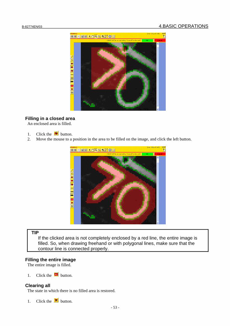
B-82774EN/03 4.BASIC OPERATIONS
- 53 -
Filling in a closed area An enclosed area is filled. 1. Click the button. 2. Move the mouse to a position in the area to be filled on the image, and click the left button.
TIP If the clicked area is not completely enclosed by a red line, the entire image is
filled. So, when drawing freehand or with polygonal lines, make sure that the contour line is connected properly.
Filling the entire image
The entire image is filled. 1. Click the button.
Clearing all The state in which there is no filled area is restored. 1. Click the button.
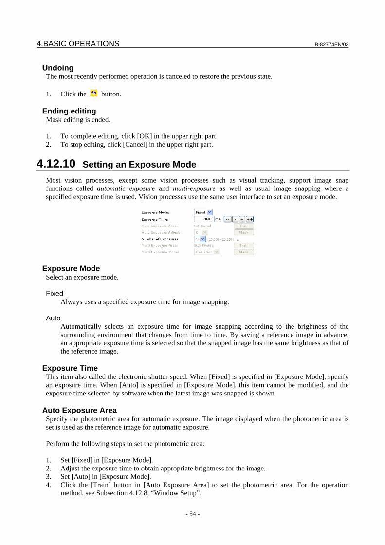
4.BASIC OPERATIONS B-82774EN/03
- 54 -
Undoing
The most recently performed operation is canceled to restore the previous state. 1. Click the button.
Ending editing Mask editing is ended. 1. To complete editing, click [OK] in the upper right part. 2. To stop editing, click [Cancel] in the upper right part.
4.12.10 Setting an Exposure Mode Most vision processes, except some vision processes such as visual tracking, support image snap functions called automatic exposure and multi-exposure as well as usual image snapping where a specified exposure time is used. Vision processes use the same user interface to set an exposure mode.
Exposure Mode Select an exposure mode. Fixed Always uses a specified exposure time for image snapping. Auto Automatically selects an exposure time for image snapping according to the brightness of the
surrounding environment that changes from time to time. By saving a reference image in advance, an appropriate exposure time is selected so that the snapped image has the same brightness as that of the reference image.
Exposure Time
This item also called the electronic shutter speed. When [Fixed] is specified in [Exposure Mode], specify an exposure time. When [Auto] is specified in [Exposure Mode], this item cannot be modified, and the exposure time selected by software when the latest image was snapped is shown.
Auto Exposure Area Specify the photometric area for automatic exposure. The image displayed when the photometric area is set is used as the reference image for automatic exposure. Perform the following steps to set the photometric area: 1. Set [Fixed] in [Exposure Mode]. 2. Adjust the exposure time to obtain appropriate brightness for the image. 3. Set [Auto] in [Exposure Mode]. 4. Click the [Train] button in [Auto Exposure Area] to set the photometric area. For the operation
method, see Subsection 4.12.8, “Window Setup”.
B-82774EN/03 4.BASIC OPERATIONS
- 55 -
5. If there is any area to be ignored in the photometric area, click the [Mask] button to mask the area to be ignored. For information on how to set a mask, see Subsection 4.12.9, “Editing Masks".
TIP 1 In [Auto Exposure Mode], a completely white or black area of the image cannot
be specified. Set an area in intermediate gray shades as the photometric area. 2 Areas that show large changes in brightness are not appropriate for [Auto
Exposure Area]. For example, in an area that might contain a workpiece, it is impossible to make stable measurements because the visible brightness changes largely depending on whether the workpiece is present or not. Choose a background area instead.
Auto Exposure Adjust
Fine adjustments can be made for automatic exposure to obtain slightly brighter or darker images than the set reference image. A value from -5 to +5 can be selected. As the value increases in the positive direction, snapped images become brighter, and as the value decreases in the negative direction, snapped images become darker.
Number of Exposure The multi-exposure function snaps multiple images by changing exposure time and combines them to generate an image with a wide dynamic range. Specify the number of images to be snapped. A value from 1 to 6 can be specified. As more images are snapped, a wider dynamic range results, but a longer time is required for image snapping.
Multi Exposure Area Specify the photometric area used for multi-exposure. Image synthesis is performed based on the brightness in the photometric area. To set the photometric area, click the [Train] button to set a window. For information on how to set a window, see Subsection 4.12.8, “Window Setup”. When the photometric area includes an area of which brightness is to be ignored, click the [Mask] button to mask the area to be ignored. For information on how to set a mask, see Subsection 4.12.9, “Editing Masks".
Multi Exposure Mode Select a method for image synthesis in multi-exposure. Deviation
The standard deviation of the image brightness in the photometric area is calculated, and synthesis is performed so that slight halation occurs in the image. This is the default setting.
Maximum
Synthesis is performed so that no halation occurs in the image in the photometric area. If halation occurs at even one point in the photometric area, the other part becomes relatively dark.
Average
Synthesis is performed simply averaging the gray level of pixels. This method can provide the widest dynamic range but might make the entire image darker.
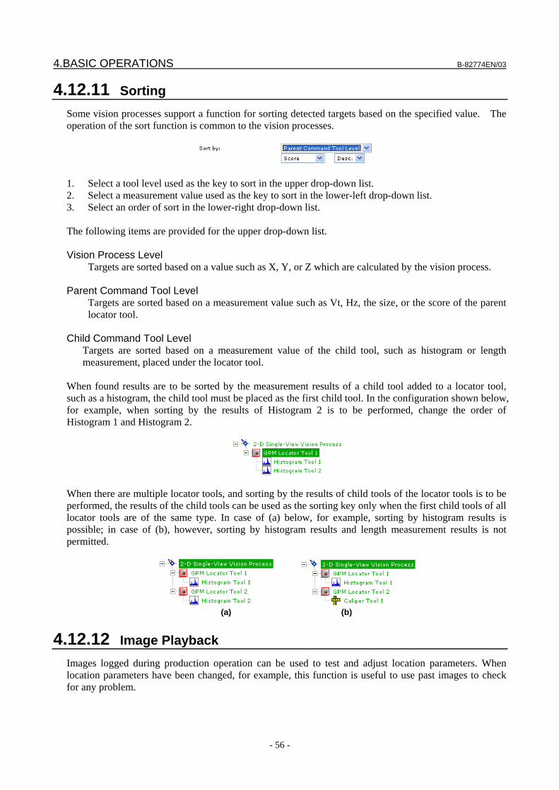
4.BASIC OPERATIONS B-82774EN/03
- 56 -
4.12.11 Sorting Some vision processes support a function for sorting detected targets based on the specified value. The operation of the sort function is common to the vision processes.
1. Select a tool level used as the key to sort in the upper drop-down list. 2. Select a measurement value used as the key to sort in the lower-left drop-down list. 3. Select an order of sort in the lower-right drop-down list. The following items are provided for the upper drop-down list. Vision Process Level
Targets are sorted based on a value such as X, Y, or Z which are calculated by the vision process. Parent Command Tool Level
Targets are sorted based on a measurement value such as Vt, Hz, the size, or the score of the parent locator tool.
Child Command Tool Level
Targets are sorted based on a measurement value of the child tool, such as histogram or length measurement, placed under the locator tool.
When found results are to be sorted by the measurement results of a child tool added to a locator tool, such as a histogram, the child tool must be placed as the first child tool. In the configuration shown below, for example, when sorting by the results of Histogram 2 is to be performed, change the order of Histogram 1 and Histogram 2.
When there are multiple locator tools, and sorting by the results of child tools of the locator tools is to be performed, the results of the child tools can be used as the sorting key only when the first child tools of all locator tools are of the same type. In case of (a) below, for example, sorting by histogram results is possible; in case of (b), however, sorting by histogram results and length measurement results is not permitted.
(a) (b)
4.12.12 Image Playback Images logged during production operation can be used to test and adjust location parameters. When location parameters have been changed, for example, this function is useful to use past images to check for any problem.
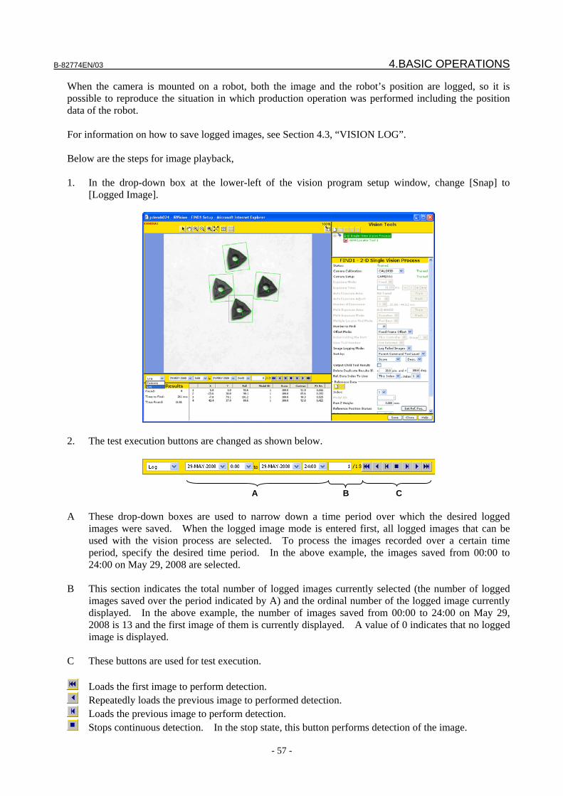
B-82774EN/03 4.BASIC OPERATIONS
- 57 -
When the camera is mounted on a robot, both the image and the robot’s position are logged, so it is possible to reproduce the situation in which production operation was performed including the position data of the robot. For information on how to save logged images, see Section 4.3, “VISION LOG”. Below are the steps for image playback, 1. In the drop-down box at the lower-left of the vision program setup window, change [Snap] to
[Logged Image].
2. The test execution buttons are changed as shown below.
A B C A These drop-down boxes are used to narrow down a time period over which the desired logged
images were saved. When the logged image mode is entered first, all logged images that can be used with the vision process are selected. To process the images recorded over a certain time period, specify the desired time period. In the above example, the images saved from 00:00 to 24:00 on May 29, 2008 are selected.
B This section indicates the total number of logged images currently selected (the number of logged
images saved over the period indicated by A) and the ordinal number of the logged image currently displayed. In the above example, the number of images saved from 00:00 to 24:00 on May 29, 2008 is 13 and the first image of them is currently displayed. A value of 0 indicates that no logged image is displayed.
C These buttons are used for test execution.
Loads the first image to perform detection. Repeatedly loads the previous image to performed detection. Loads the previous image to perform detection. Stops continuous detection. In the stop state, this button performs detection of the image.
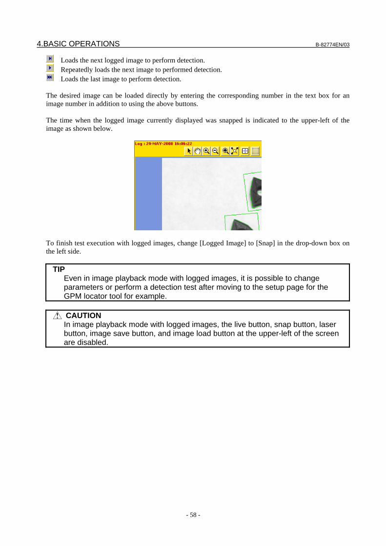
4.BASIC OPERATIONS B-82774EN/03
- 58 -
Loads the next logged image to perform detection. Repeatedly loads the next image to performed detection. Loads the last image to perform detection.
The desired image can be loaded directly by entering the corresponding number in the text box for an image number in addition to using the above buttons. The time when the logged image currently displayed was snapped is indicated to the upper-left of the image as shown below.
To finish test execution with logged images, change [Logged Image] to [Snap] in the drop-down box on the left side.
TIP Even in image playback mode with logged images, it is possible to change
parameters or perform a detection test after moving to the setup page for the GPM locator tool for example.
CAUTION
In image playback mode with logged images, the live button, snap button, laser button, image save button, and image load button at the upper-left of the screen are disabled.
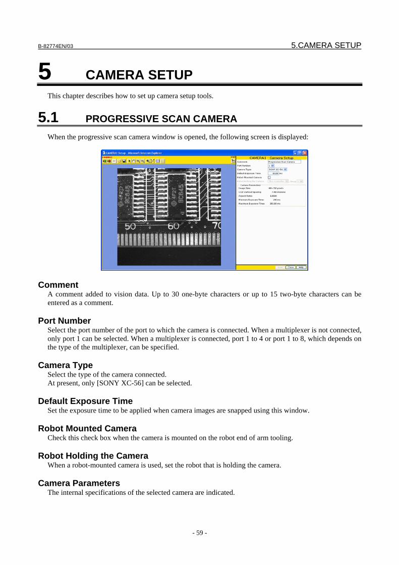
B-82774EN/03 5.CAMERA SETUP
- 59 -
5 CAMERA SETUP This chapter describes how to set up camera setup tools.
5.1 PROGRESSIVE SCAN CAMERA When the progressive scan camera window is opened, the following screen is displayed:
Comment A comment added to vision data. Up to 30 one-byte characters or up to 15 two-byte characters can be entered as a comment.
Port Number Select the port number of the port to which the camera is connected. When a multiplexer is not connected, only port 1 can be selected. When a multiplexer is connected, port 1 to 4 or port 1 to 8, which depends on the type of the multiplexer, can be specified.
Camera Type Select the type of the camera connected. At present, only [SONY XC-56] can be selected.
Default Exposure Time Set the exposure time to be applied when camera images are snapped using this window.
Robot Mounted Camera Check this check box when the camera is mounted on the robot end of arm tooling.
Robot Holding the Camera When a robot-mounted camera is used, set the robot that is holding the camera.
Camera Parameters The internal specifications of the selected camera are indicated.
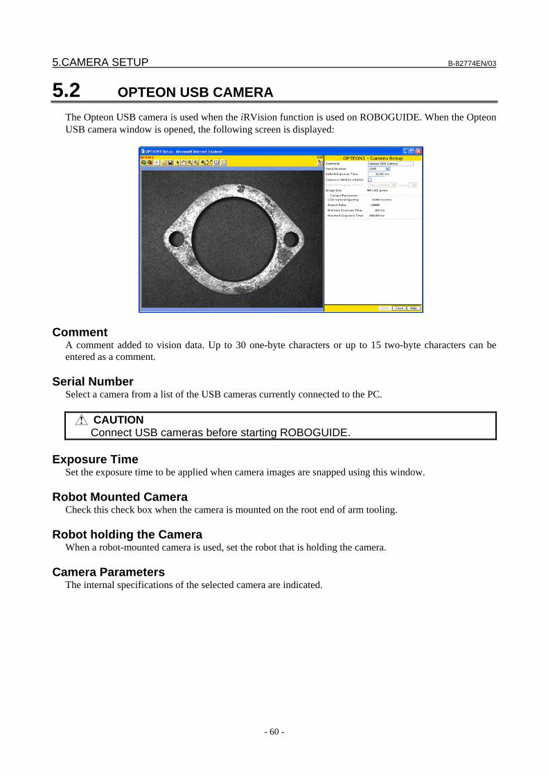
5.CAMERA SETUP B-82774EN/03
- 60 -
5.2 OPTEON USB CAMERA The Opteon USB camera is used when the iRVision function is used on ROBOGUIDE. When the Opteon USB camera window is opened, the following screen is displayed:
Comment A comment added to vision data. Up to 30 one-byte characters or up to 15 two-byte characters can be entered as a comment.
Serial Number Select a camera from a list of the USB cameras currently connected to the PC.
CAUTION Connect USB cameras before starting ROBOGUIDE.
Exposure Time
Set the exposure time to be applied when camera images are snapped using this window.
Robot Mounted Camera Check this check box when the camera is mounted on the root end of arm tooling.
Robot holding the Camera When a robot-mounted camera is used, set the robot that is holding the camera.
Camera Parameters The internal specifications of the selected camera are indicated.
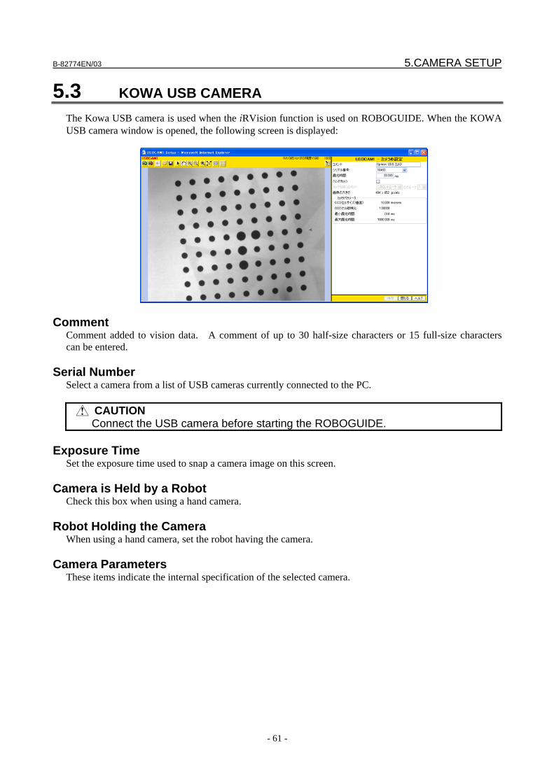
B-82774EN/03 5.CAMERA SETUP
- 61 -
5.3 KOWA USB CAMERA The Kowa USB camera is used when the iRVision function is used on ROBOGUIDE. When the KOWA USB camera window is opened, the following screen is displayed:
Comment Comment added to vision data. A comment of up to 30 half-size characters or 15 full-size characters can be entered.
Serial Number Select a camera from a list of USB cameras currently connected to the PC.
CAUTION Connect the USB camera before starting the ROBOGUIDE.
Exposure Time
Set the exposure time used to snap a camera image on this screen.
Camera is Held by a Robot Check this box when using a hand camera.
Robot Holding the Camera When using a hand camera, set the robot having the camera.
Camera Parameters These items indicate the internal specification of the selected camera.
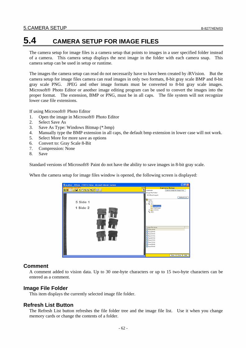
5.CAMERA SETUP B-82774EN/03
- 62 -
5.4 CAMERA SETUP FOR IMAGE FILES The camera setup for image files is a camera setup that points to images in a user specified folder instead of a camera. This camera setup displays the next image in the folder with each camera snap. This camera setup can be used in setup or runtime. The images the camera setup can read do not necessarily have to have been created by iRVision. But the camera setup for image files camera can read images in only two formats, 8-bit gray scale BMP and 8-bit gray scale PNG. JPEG and other image formats must be converted to 8-bit gray scale images. Microsoft® Photo Editor or another image editing program can be used to convert the images into the proper format. The extension, BMP or PNG, must be in all caps. The file system will not recognize lower case file extensions. If using Microsoft® Photo Editor 1. Open the image in Microsoft® Photo Editor 2. Select Save As 3. Save As Type: Windows Bitmap (*.bmp) 4. Manually type the BMP extension in all caps, the default bmp extension in lower case will not work. 5. Select More for more save as options 6. Convert to: Gray Scale 8-Bit 7. Compression: None 8. Save Standard versions of Microsoft® Paint do not have the ability to save images in 8-bit gray scale. When the camera setup for image files window is opened, the following screen is displayed:
Comment A comment added to vision data. Up to 30 one-byte characters or up to 15 two-byte characters can be entered as a comment.
Image File Folder This item displays the currently selected image file folder.
Refresh List Button The Refresh List button refreshes the file folder tree and the image file list. Use it when you change memory cards or change the contents of a folder.
B-82774EN/03 5.CAMERA SETUP
- 63 -
File Folder Tree This item displays the tree of file folders on the robot. Click on a “+” character to expand a folder, “-” to collapse it. Click on a folder name to select it.
Image File List This item displays the list of image files in the selected folder. Click on an image file to open and display it.
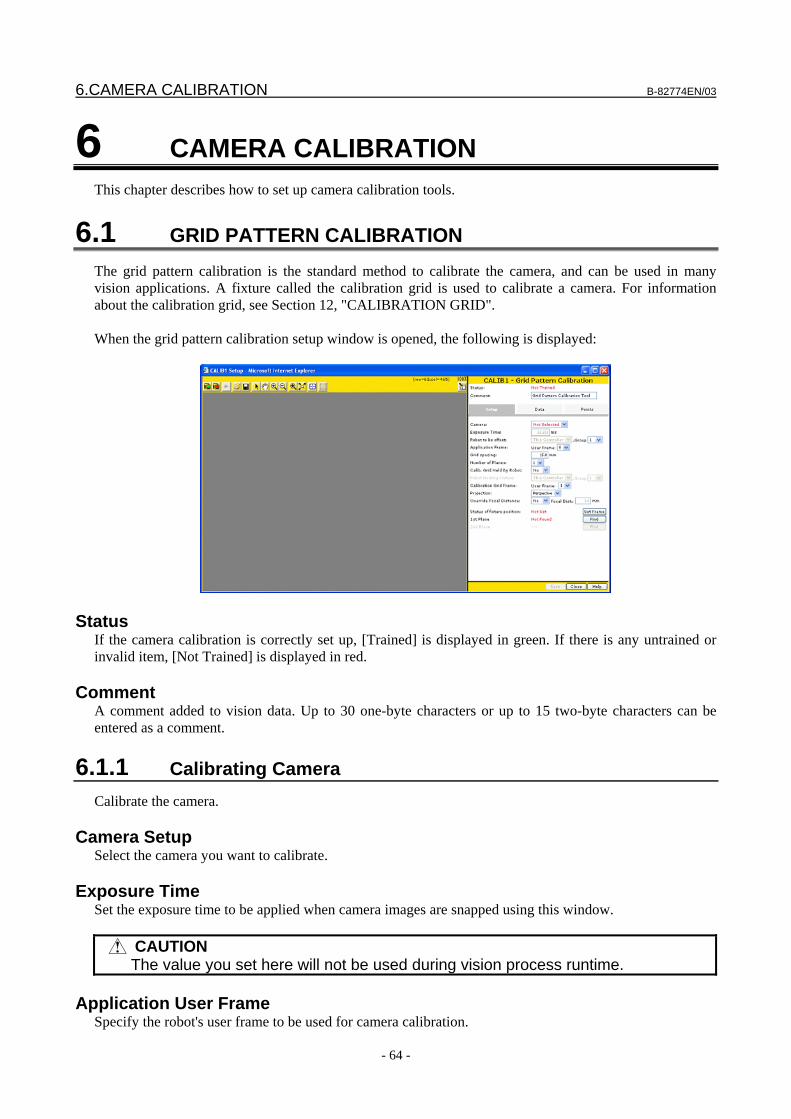
6.CAMERA CALIBRATION B-82774EN/03
- 64 -
6 CAMERA CALIBRATION This chapter describes how to set up camera calibration tools.
6.1 GRID PATTERN CALIBRATION The grid pattern calibration is the standard method to calibrate the camera, and can be used in many vision applications. A fixture called the calibration grid is used to calibrate a camera. For information about the calibration grid, see Section 12, "CALIBRATION GRID". When the grid pattern calibration setup window is opened, the following is displayed:
Status If the camera calibration is correctly set up, [Trained] is displayed in green. If there is any untrained or invalid item, [Not Trained] is displayed in red.
Comment A comment added to vision data. Up to 30 one-byte characters or up to 15 two-byte characters can be entered as a comment.
6.1.1 Calibrating Camera Calibrate the camera.
Camera Setup Select the camera you want to calibrate.
Exposure Time Set the exposure time to be applied when camera images are snapped using this window.
CAUTION The value you set here will not be used during vision process runtime.
Application User Frame
Specify the robot's user frame to be used for camera calibration.
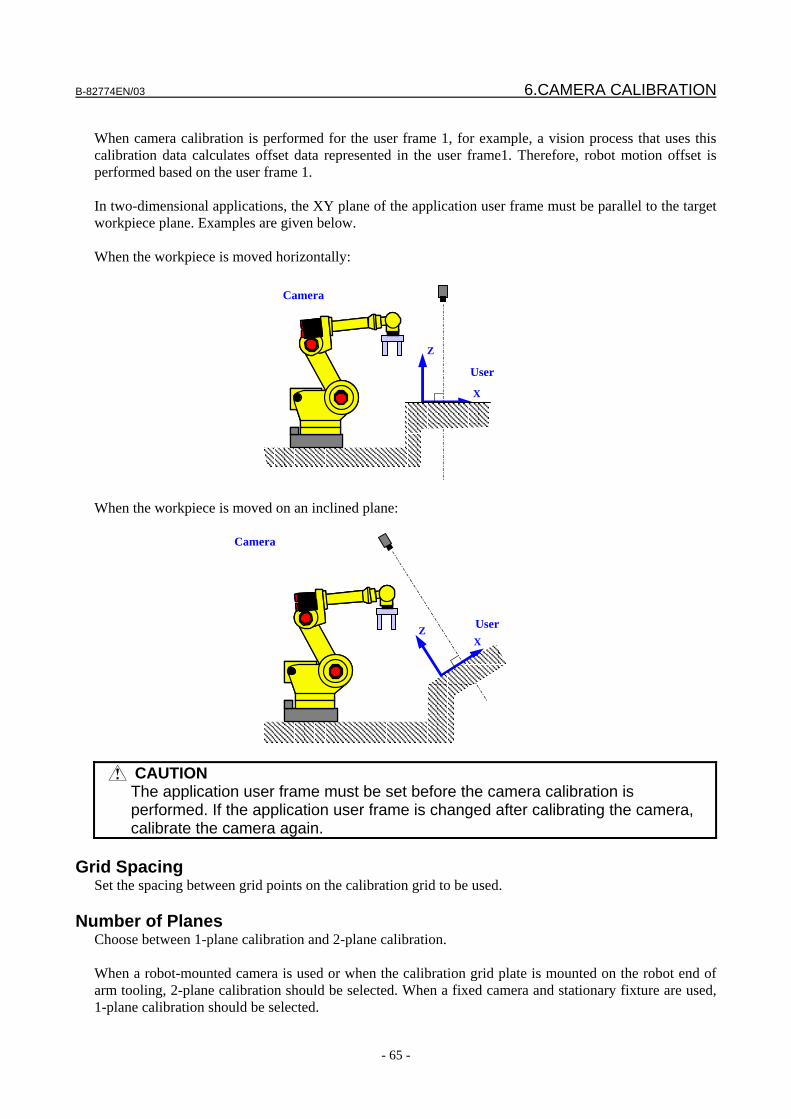
B-82774EN/03 6.CAMERA CALIBRATION
- 65 -
When camera calibration is performed for the user frame 1, for example, a vision process that uses this calibration data calculates offset data represented in the user frame1. Therefore, robot motion offset is performed based on the user frame 1. In two-dimensional applications, the XY plane of the application user frame must be parallel to the target workpiece plane. Examples are given below. When the workpiece is moved horizontally:
When the workpiece is moved on an inclined plane:
CAUTION The application user frame must be set before the camera calibration is
performed. If the application user frame is changed after calibrating the camera, calibrate the camera again.
Grid Spacing
Set the spacing between grid points on the calibration grid to be used.
Number of Planes Choose between 1-plane calibration and 2-plane calibration. When a robot-mounted camera is used or when the calibration grid plate is mounted on the robot end of arm tooling, 2-plane calibration should be selected. When a fixed camera and stationary fixture are used, 1-plane calibration should be selected.
User X
Z
X
Z
User
X
Camera
Camera
6.CAMERA CALIBRATION B-82774EN/03
- 66 -
Calib. Grid Held by Robot Select the installation method of the calibration grid. No The calibration grid is secured to a table or another place to perform calibration. Yes The calibration grid is mounted on the robot end of arm tooling to perform calibration.
Robot Holding Fixture If you choose [Yes] for [Calib. Grid Held by Robot], specify the robot that is holding the calibration grid.
Calibration Grid Frame Calibration grid frame indicates the position and orientation of the calibration grid when the camera calibration was performed. When the calibration grid is secured in a fixed location, its position relative to the robot base frame should be set in a user frame area. On this screen, you select the user frame number in which the calibration grid frame information has been set. When the calibration grid is attached to the robot end of arm tooling, its position relative to the robot mechanical interface frame (the robot wrist flange) should be set in a user tool area. On this screen, you select the user tool number in which the calibration grid frame information has been set. Detailed information on how to teach the calibration grid frame is described in Section 12.2, "CALIBRATION GRID FRAME".
Projection Select [Perspective].
Override Focal Distance Usually, leave this item set to [No]. When the grid pattern is found, the focal distance will be calculated automatically. When 2-plane calibration is performed, a value close to the nominal focal distance of the lens is calculated. (For example, when the nominal f value of the lens used is 12 mm, 12.1 mm might be calculated.) A correct calibration can be regarded as having been made if the calculated value is close to the nominal value. When the calibration grid is placed to be perpendicular to the optical axis of the camera and 1-plane calibration is performed, select [Yes] and set the value of the nominal focal distance of the lens because theoretically it is difficult to calculate a correct focal distance.
Status of fixture position When the calibration grid is in a fixed location, click the [Set] button. Based on the data of the specified frames, iRVision calculates how and where the calibration grid is positioned in the application user frame, and saves the result.
CAUTION If the position of the calibration grid is changed, e.g., when re-calibrating the
camera, it is necessary to recalculate the fixture position by setting the user frame again that contains the calibration grid frame and then clicking the [Set] button to update the fixture position.
When the calibration grid is mounted on the robot end of arm tooling, this button is disabled. The positioning information of the grid pattern is calculated and saved when you perform the next step of finding the grid pattern.
B-82774EN/03 6.CAMERA CALIBRATION
- 67 -
Finding the grid pattern
The grid pattern is found to calculate calibration data. 1. To capture the image of the calibration grid, click the (red) button.
CAUTION The calibration grid does not have to fill the field of view, but the calibration will
be less accurate if circles of the grid pattern appear only a part in the image. Make sure that the image is filled with circles of the grid pattern; do not care about some of the circles appearing outside the image.
2. Click the [Find] button of [1st Plane]. 3. Specify the grid range with the displayed red rectangle.
4. Click the [OK] button. 5. When the grid pattern is found successfully, crosshairs (+) appear at the center of each of the found
circles.
6. Check that blue crosshairs (+) appear in the four large circles. Also, check that green crosshairs (+)
appear in small circles. There might be one or two undetected small circles. For 1-plane calibration, this completes the procedure for calibration.
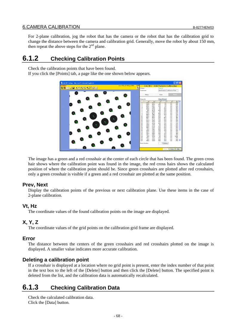
6.CAMERA CALIBRATION B-82774EN/03
- 68 -
For 2-plane calibration, jog the robot that has the camera or the robot that has the calibration grid to change the distance between the camera and calibration grid. Generally, move the robot by about 150 mm, then repeat the above steps for the 2nd plane.
6.1.2 Checking Calibration Points Check the calibration points that have been found. If you click the [Points] tab, a page like the one shown below appears.
The image has a green and a red crosshair at the center of each circle that has been found. The green cross hair shows where the calibration point was found in the image, the red cross hairs shows the calculated position of where the calibration point should be. Since green crosshairs are plotted after red crosshairs, only a green crosshair is visible if a green and a red crosshair are plotted at the same position.
Prev, Next Display the calibration points of the previous or next calibration plane. Use these items in the case of 2-plane calibration.
Vt, Hz The coordinate values of the found calibration points on the image are displayed.
X, Y, Z The coordinate values of the grid points on the calibration grid frame are displayed.
Error The distance between the centers of the green crosshairs and red crosshairs plotted on the image is displayed. A smaller value indicates more accurate calibration.
Deleting a calibration point If a crosshair is displayed at a location where no grid point is present, enter the index number of that point in the text box to the left of the [Delete] button and then click the [Delete] button. The specified point is deleted from the list, and the calibration data is automatically recalculated.
6.1.3 Checking Calibration Data Check the calculated calibration data. Click the [Data] button.
B-82774EN/03 6.CAMERA CALIBRATION
- 69 -
Focal Distance The calculated focal distance of the lens is displayed. Check that the value is appropriate for the lens in use. In the case of 1-plane calibration, if the W and P values in the [Position of Camera Relative to Calibration Grid] section are both less than several ± degrees, the focal distance cannot be measured accurately. Therefore, in the [Setup] tab, set [Override Focal Distance] to [Yes] and enter the nominal focal distance of the lens in use. If you enter the focal distance, the calibration data is automatically recalculated.
Lens Distortion The calculated lens distortion coefficient is displayed. A larger absolute value indicates greater lens distortion. Generally, lenses with shorter focal distances are said to have greater distortion. Grid pattern calibration returns accurate coordinates by using this calculated lens distortion when accurately converting the image frame to the robot frame.
Image Center The coordinates of the center of the image are displayed.
Magnification The size of a pixel in millimeters on the grid pattern plane (1st plane in the case of 2-plane calibration) is displayed. The value indicates how many millimeters are equivalent to a pixel. If the grid pattern plane is not vertical to the optical axis of the camera, the magnification near the center of the image is displayed.
CCD Vertical Spacing The physical size of a pixel of the light receiving element of the camera in use is displayed.
Aspect Ratio The aspect ratio of a pixel of the image is displayed.
Maximum / Average Error The average and maximum errors of all the calibration points shown in the [Points] tab table are displayed.
Position of Camera relative to Calibration Grid
The position of the camera relative to the calibration grid frame is displayed. For grid frame setting, see Section 12, "CALIBRATION GRID".
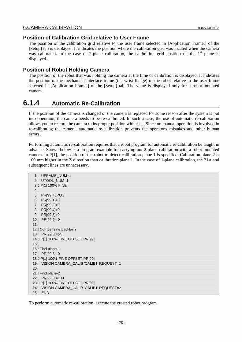
6.CAMERA CALIBRATION B-82774EN/03
- 70 -
Position of Calibration Grid relative to User Frame The position of the calibration grid relative to the user frame selected in [Application Frame:] of the [Setup] tab is displayed. It indicates the position where the calibration grid was located when the camera was calibrated. In the case of 2-plane calibration, the calibration grid position on the 1st plane is displayed.
Position of Robot Holding Camera The position of the robot that was holding the camera at the time of calibration is displayed. It indicates the position of the mechanical interface frame (the wrist flange) of the robot relative to the user frame selected in [Application Frame:] of the [Setup] tab. The value is displayed only for a robot-mounted camera.
6.1.4 Automatic Re-Calibration If the position of the camera is changed or the camera is replaced for some reason after the system is put into operation, the camera needs to be re-calibrated. In such a case, the use of automatic re-calibration allows you to restore the camera to its proper position with ease. Since no manual operation is involved in re-calibrating the camera, automatic re-calibration prevents the operator's mistakes and other human errors. Performing automatic re-calibration requires that a robot program for automatic re-calibration be taught in advance. Shown below is a program example for carrying out 2-plane calibration with a robot mounted camera. In P[1], the position of the robot to detect calibration plane 1 is specified. Calibration plane 2 is 100 mm higher in the Z direction than calibration plane 1. In the case of 1-plane calibration, the 21st and subsequent lines are unnecessary. 1: UFRAME_NUM=1 2: UTOOL_NUM=1 3:J P[1] 100% FINE 4: 5: PR[99]=LPOS 6: PR[99,1]=0 7: PR[99,2]=0 8: PR[99,4]=0 9: PR[99,5]=0 10: PR[99,6]=0 11: 12:! Compensate backlash 13: PR[99,3]=(-5) 14:J P[1] 100% FINE OFFSET,PR[99] 15: 16:! Find plane-1 17: PR[99,3]=0 18:J P[1] 100% FINE OFFSET,PR[99] 19: VISION CAMERA_CALIB 'CALIB1' REQUEST=1 20: 21:! Find plane-2 22: PR[99,3]=100 23:J P[1] 100% FINE OFFSET,PR[99] 24: VISION CAMERA_CALIB 'CALIB1' REQUEST=2 25: END
To perform automatic re-calibration, execute the created robot program.
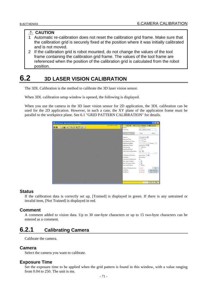
B-82774EN/03 6.CAMERA CALIBRATION
- 71 -
CAUTION 1 Automatic re-calibration does not reset the calibration grid frame. Make sure that
the calibration grid is securely fixed at the position where it was initially calibrated and is not moved.
2 If the calibration grid is robot mounted, do not change the values of the tool frame containing the calibration grid frame. The values of the tool frame are referenced when the position of the calibration grid is calculated from the robot position.
6.2 3D LASER VISION CALIBRATION The 3DL Calibration is the method to calibrate the 3D laser vision sensor. When 3DL calibration setup window is opened, the following is displayed. When you use the camera in the 3D laser vision sensor for 2D application, the 3DL calibration can be used for the 2D application. However, in such a case, the XY plane of the application frame must be parallel to the workpiece plane. See 6.1 "GRID PATTERN CALIBRATION" for details.
Status If the calibration data is correctly set up, [Trained] is displayed in green. If there is any untrained or invalid item, [Not Trained] is displayed in red.
Comment A comment added to vision data. Up to 30 one-byte characters or up to 15 two-byte characters can be entered as a comment.
6.2.1 Calibrating Camera Calibrate the camera.
Camera Select the camera you want to calibrate.
Exposure Time Set the exposure time to be applied when the grid pattern is found in this window, with a value ranging from 0.04 to 250. The unit is ms.
6.CAMERA CALIBRATION B-82774EN/03
- 72 -
Laser Exposure Time
Set the exposure time to be applied when laser slits are found in this window, with a value ranging from 0.04 to 250. The unit is ms.
Robot to be offset Specify the target robot position offset by setting its controller and group number.
Application Frame Specify the number of the user frame to be used for robot position offset. Measurement results are converted to values in the set user frame before output.
Grid Spacing Enter the spacing between grid points on the calibration grid used. The unit is mm.
Number of Planes Show the number of planes to be calibrated. Two planes are selected. This setting cannot be changed.
Calib. Grid Held by Robot Select the installation status of the calibration grid. Select [No] if the calibration grid is not moved with respect to the user frame, or select [Yes] if the calibration grid is mounted on the robot.
Robot Holding Fixture This item is set only when [Yes] is selected in [Calib. Grid Held by Robot]. Select the robot that has the calibration plate. In [Group], set the group number of the robot.
Calibration Grid Frame Calibration grid frame indicates the position and orientation of the calibration grid when the camera calibration was performed. When the calibration grid is in a fixed location, its position relative to the robot base frame should be set in a user frame area. On this screen, you select the user frame number in which the calibration grid frame information has been set. When the calibration grid is attached to the robot end of arm tooling, its position relative to the robot mechanical interface frame (the robot wrist flange) should be set in a user tool area. On this screen, you select the user tool number in which the calibration grid frame information has been set. Detailed information on how to set the calibration grid frame is described in Section 12.2, "CALIBRATION GRID FRAME".
Projection [Perspective] is selected. This setting cannot be changed.
Override Focal Length The focal distance of the lens used. [No] is selected. This setting cannot be changed.
Min. Laser Contrast Set the threshold of contrast applicable when a laser point sequence is to be found. Set a value ranging from 1 to 254. The default value is 50.
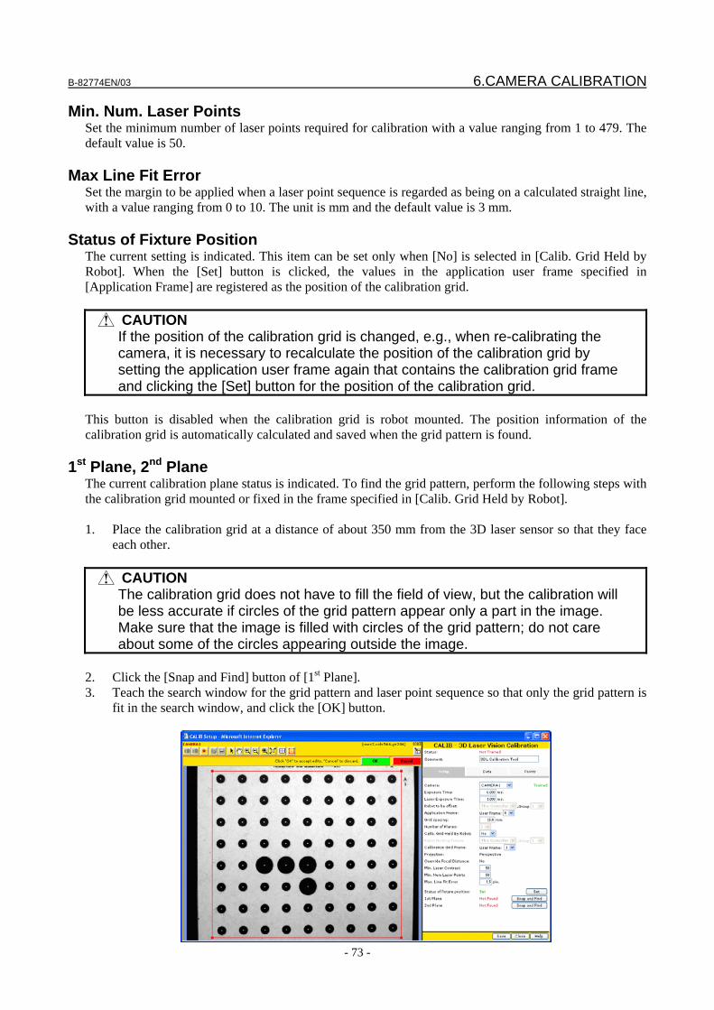
B-82774EN/03 6.CAMERA CALIBRATION
- 73 -
Min. Num. Laser Points Set the minimum number of laser points required for calibration with a value ranging from 1 to 479. The default value is 50.
Max Line Fit Error Set the margin to be applied when a laser point sequence is regarded as being on a calculated straight line, with a value ranging from 0 to 10. The unit is mm and the default value is 3 mm.
Status of Fixture Position The current setting is indicated. This item can be set only when [No] is selected in [Calib. Grid Held by Robot]. When the [Set] button is clicked, the values in the application user frame specified in [Application Frame] are registered as the position of the calibration grid.
CAUTION If the position of the calibration grid is changed, e.g., when re-calibrating the
camera, it is necessary to recalculate the position of the calibration grid by setting the application user frame again that contains the calibration grid frame and clicking the [Set] button for the position of the calibration grid.
This button is disabled when the calibration grid is robot mounted. The position information of the calibration grid is automatically calculated and saved when the grid pattern is found.
1st Plane, 2nd Plane The current calibration plane status is indicated. To find the grid pattern, perform the following steps with the calibration grid mounted or fixed in the frame specified in [Calib. Grid Held by Robot]. 1. Place the calibration grid at a distance of about 350 mm from the 3D laser sensor so that they face
each other.
CAUTION The calibration grid does not have to fill the field of view, but the calibration will
be less accurate if circles of the grid pattern appear only a part in the image. Make sure that the image is filled with circles of the grid pattern; do not care about some of the circles appearing outside the image.
2. Click the [Snap and Find] button of [1st Plane]. 3. Teach the search window for the grid pattern and laser point sequence so that only the grid pattern is
fit in the search window, and click the [OK] button.
6.CAMERA CALIBRATION B-82774EN/03
- 74 -
4. Check that almost all circles are found and the laser slits are found clearly. If the location is
successful, [Found] is indicated in [1st Plane]. 5. Place the calibration grid at a distance of about 450 mm from the 3D laser sensor so that they face
each other. 6. Click the [Snap and Find] button of [2nd Plane]. 7. Teach the search window for the grid pattern and laser point sequence so that only the grid pattern is
fit in the search window, and click the [OK] button. 8. Check that almost all circles are found and the laser slits are found clearly. If the location is
successful, [Found] is indicated in [2nd Plane].
6.2.2 Checking Calibration Points Check the calibration points that have been found. When the [Points] tab is clicked, a window like the one shown below appears.
1. Check for any crosshairs that appear in a place other than the grid points. 2. If there is an incorrect point, enter the number of that point in the text box on the right of [Point
Number], then click [Delete] button. The image has a green and a red crosshair at the center of each circle that has been found. The green cross hair shows where the calibration point was found in the image, the red cross hairs shows the calculated position of where the calibration point should be. Since green crosshairs are plotted after red crosshairs, only a green crosshair is visible if a green and a red crosshair are plotted at the same position.
Prev, Next Display the calibration points of the previous or next calibration plane. Use these items in the case of 2-plane calibration.
Vt, Hz The coordinate values of the found calibration points on the image are displayed.
X, Y, Z The coordinate values of the grid points on the calibration grid frame are displayed.
Error The distance between the centers of the green crosshairs and red crosshairs plotted on the image is displayed. A smaller value indicates more accurate calibration.
B-82774EN/03 6.CAMERA CALIBRATION
- 75 -
Deleting a calibration point If a crosshair is displayed at a location where no grid point is present, enter the index number of that point in the text box to the left of the [Delete] button and then click the [Delete] button. The specified point is deleted from the list, and the calibration data is automatically recalculated.
6.2.3 Checking Calibration Data Click the [Data] tab.
Focal Distance The calculated focal distance of the lens is displayed. Check that the value is appropriate for the lens in use.
Lens Distortion The calculated lens distortion coefficient is displayed. A larger absolute value indicates greater lens distortion. Generally, lenses with shorter focal distances are said to have greater distortion. Grid pattern calibration returns accurate coordinates by using this calculated lens distortion when accurately converting the image frame to the robot frame.
Image Center The coordinates of the center of the image are displayed.
Magnification The size of a pixel in millimeters on the grid pattern plane is displayed. The value indicates how many millimeters are equivalent to a pixel. If the grid pattern plane is not vertical to the optical axis of the camera, the magnification near the center of the image is displayed.
CCD Vertical Spacing The physical size of a pixel of the light receiving element of the camera in use is displayed.
Aspect Ratio The aspect ratio of a pixel of the image is displayed.
Maximum / Average Error The average and maximum errors of each calibration point shown in the [Points] tab table are displayed.
Position of Camera relative to Calibration Grid The position of the camera relative to the calibration grid frame is displayed.
6.CAMERA CALIBRATION B-82774EN/03
- 76 -
For grid frame setting, see Section 12, "CALIBRATION GRID".
Position of Calibration Grid relative to User Frame The position of the calibration grid relative to the user frame selected in [Application Frame:] of the [Setup] tab is displayed. It indicates the position where the calibration grid was located when the camera was calibrated.
Position of Robot Holding Camera The position of the robot that was holding the camera at the time of calibration is displayed. It indicates the position of the mechanical interface frame (the wrist flange) of the robot relative to the user frame selected in [Application Frame:] of the [Setup] tab. The value is displayed only for a robot-mounted camera.
Camera frame relative to the robot [Camera frame relative to the robot] on the [Data] tab indicates the position of the frame which shows the shooting direction of the camera relative to the mechanical interface frame of the robot (the wrist flange of the robot) when the 3D laser sensor is robot mounted. The camera frame is defined so that the origin is located 400 mm (or 600mm; depending on the standoff of the 3D laser sensor) from the lens focus on the optical axis of the camera and the Z-axis is located parallel to the optical axis of the camera. If this value is set for the user tool of the robot and a jog is performed on the basis of the user tool, it is possible to jog the robot without changing the camera distance or to rotate the camera about the optical axis.
Laser frame relative to the robot [Laser frame relative to the robot] on the [Data] tab indicates the position of the frame which shows the laser emitting direction relative to the mechanical interface frame of the robot (the wrist flange of the robot) when the 3D laser sensor is robot mounted. This frame is defined so that the origin is located 400 mm (or 600mm; depending on the standoff of the 3D laser sensor) from the lens focus of the camera on the line of intersection of two slit laser beams and the Z-axis is located parallel to the line of intersection of the two slit laser beams. If this value is set for the user tool of the robot and a jog is performed on the basis of the user tool, it is possible to move the robot in parallel with the two slit laser beams or to rotate the camera about the laser beams.
6.2.4 Automatic Re-Calibration If the position of the 3D laser sensor is changed or the sensor is replaced for some reason after the system is put into operation, the 3D laser sensor needs to be re-calibrated. In such a case, the use of automatic re-calibration allows you to restore the sensor to its proper position with ease. Since no manual operation is involved in re-calibrating the sensor, automatic re-calibration prevents the operator's mistakes and other human errors. Performing automatic re-calibration requires that a robot program for automatic re-calibration be taught in advance. A program example is shown below. In P[1], the position of the robot to detect calibration plane 1 is specified. Calibration plane 2 is 100 mm higher in the Z direction than calibration plane 1.
B-82774EN/03 6.CAMERA CALIBRATION
- 77 -
1: UFRAME_NUM=1 2: UTOOL_NUM=1 3:J P[1] 100% FINE 4: 5: PR[99]=LPOS 6: PR[99,1]=0 7: PR[99,2]=0 8: PR[99,4]=0 9: PR[99,5]=0 10: PR[99,6]=0 11: 12:! Compensate backlash 13: PR[99,3]=(-5) 14:J P[1] 100% FINE OFFSET,PR[99] 15: 16:! Find plane-1 17: PR[99,3]=0 18:J P[1] 100% FINE OFFSET,PR[99] 19: VISION CAMERA_CALIB 'CALIB1' REQUEST=1 20: 21:! Find plane-2 22: PR[99,3]=100 23:J P[1] 100% FINE OFFSET,PR[99] 24: VISION CAMERA_CALIB 'CALIB1' REQUEST=2 25: END
To perform automatic re-calibration, execute the created robot program.
CAUTION 1 Automatic re-calibration does not reset the calibration grid frame. Make sure that
the calibration grid is securely fixed at the position where it was initially calibrated and is not moved.
2 If the calibration grid is robot mounted, do not change the values of the tool frame containing the calibration grid frame. The values of the tool frame are referenced when the position of the calibration grid is calculated from the robot position.
6.3 ROBOT-GENERATED GRID CALIBRATION Robot-generated grid calibration is a general-purpose camera calibration function suitable for the calibration of a wide-view-angle camera. Selecting [Robot-Generated Grid Calibration] displays a page like the one shown below.

6.CAMERA CALIBRATION B-82774EN/03
- 78 -
By selecting an element in the tree view in the upper right, you can toggle between the robot-generated grid calibration setting screen and the GPM locator tool setting screen.
6.3.1 Camera Calibration Tools If you select [Robot-Generated Grid Calibration] in the tree view, and click [Setup] tab, a setting screen will be displayed.
Camera Name From the drop-down list, choose the camera to be calibrated. When you select a camera name, the corresponding camera positioning state is displayed to the left of the drop-down box.
Exposure Time of Camera Set the exposure time to make sure that the target is detected easily. This exposure time setting is used only for calibration. For details of the individual items to be set, see Subsection 4.12.10, "Setting an Exposure Mode".
Robot to be Offset Specify the robot to be offset, by using a motion group number.
Application User Frame Specify the robot's user frame to be used for camera calibration. When camera calibration is performed for user frame 1, for example, a vision process that uses this calibration data calculates offset data represented in user frame 1. Therefore, robot motion offset is performed based on user frame 1. In two-dimensional applications, the XY plane of the application user frame must be parallel to the target workpiece plane. Examples are given below.
B-82774EN/03 6.CAMERA CALIBRATION
- 79 -
X
Z Application User Frame
Camera
X
Z
Application User Frame
X Z
Camera
X Z
When the workpiece is moved horizontally When the workpiece is moved on an inclined plane
CAUTION
The application user frame must be set in the robot controller before the camera calibration is performed. If the application user frame is changed after calibrating the camera, calibrate the camera again.
Target Held By Robot
The target positioning method information necessary to calibrate the currently selected camera is displayed. [Yes] is shown if the camera is a fixed camera], and [No] is shown if the camera is robot-mounted].
Image Logging Mode From the drop-down list, select whether to save images in the vision log.
Plane spacing Enter calibration plane spacing in mm.
Start Position Jog the robot to the measurement start position, and then click the [RECORD] button to set the measurement start position.
TIP In robot-generated grid calibration, all you set on the PC is the information
needed for target detection and the actual calibration is performed using the teach pendant of the robot. For the calibration procedure using the teach pendant, see Section 11.3, "Robot-Generated Grid Calibration".
6.3.2 Deleting unnecessary grid points If you select [Robot-Generated Grid Calibration] in the tree view, and click [Points] tab, a page like the one shown below appears.
6.CAMERA CALIBRATION B-82774EN/03
- 80 -
The image has a blue crosshair plotted on each calibration point in calibration plane 1 and a purple crosshair plotted on each calibration point in calibration plane 2, at the center of each circle that has been found. A calibration point number is shown at the lower right of each crosshair. A red crosshair shows the 3D position of an individual circle that is obtained by projecting the circle onto the image by means of the calculated calibration data. Since blue and purple crosshairs are plotted after red crosshairs, a red crosshair is not visible if a blue or purple crosshair and a red crosshair are plotted at the same position.
Vt, Hz The coordinate values of the found calibration points on the image are displayed.
X, Y, Z The coordinate values of the grid points on the user frame to be offset are displayed.
Error The distance between the centers of the blue and purple crosshairs and the centers of the red crosshairs plotted on the image is displayed. A smaller value indicates more accurate calibration.
Deleting a calibration point If a crosshair is displayed at a location where no calibration point is present, select that point by clicking it in the list or enter the index number of the point in the text box to the left of the [Delete] button, and then click the [Delete] button. The specified point is deleted from the list, and the calibration data is automatically recalculated.
B-82774EN/03 6.CAMERA CALIBRATION
- 81 -
6.3.3 Checking the result If you select the [Robot-Generated Grid Calibration] in the tree view, and click the [Data] tab, a page like the one shown below appears.
Status If the calibration data is correctly set up, [Trained] is displayed in green. If there is any untrained or invalid item, [Not Trained] is displayed in red.
Focal Distance The calculated focal distance of the lens is displayed. Check that the focal distance is within ±5% of the nominal focal distance of the lens (the value indicated in the spec sheet).
Lens Distortion The calculated lens distortion coefficient is displayed. A larger absolute value indicates greater lens distortion. Generally, lenses with shorter focal distances are said to have greater distortion. Robot-generated grid calibration returns accurate coordinates by using this calculated lens distortion when accurately converting the image frame to the robot frame.
Magnification The size of a pixel in millimeters on calibration plane 1 is displayed. The value indicates how many millimeters are equivalent to a pixel on the image.
Image Center The position where the light passing through the center of the lens is projected is displayed. A typical lens is designed so that the light passing through the center of the lens is projected at the center of the image. Check that the image center is set to be near the center of the image.
CCD Vertical Spacing The physical size of a pixel of the light receiving element of the camera in use is displayed.
Aspect Ratio The aspect ratio of a pixel of the image is displayed.
6.CAMERA CALIBRATION B-82774EN/03
- 82 -
Maximum / Average Error
The average and maximum errors of all the calibration points shown in the [Points] tab table are displayed.
Extent of the calibration point height The range of the Z height of a calibration point on the user frame to be offset is displayed.
Position of Fixed Camera Relative to Application User Frame The position of the fixed camera relative to the user frame to be offset is displayed.
6.3.4 Automatic Re-Calibration If the position of the camera is changed or the camera is replaced for some reason after the system is put into operation, the camera needs to be re-calibrated. In such a case, the use of automatic re-calibration allows you to restore the camera to its proper position with ease. Since no manual operation is involved in re-calibrating the camera, automatic re-calibration prevents the operator's mistakes and other human errors. Robot-generated grid calibration automatically generates a calibration program. By executing this program from the first line, you can perform re-calibration.
CAUTION Automatic re-calibration does not reset the target positioning information. Make
sure that the target is securely fixed at the position where it was initially calibrated and is not moved.
6.4 VISUAL TRACKING CALIBRATION The visual tracking calibration is the camera calibration method dedicated to the visual tracking application. When camera calibration of visual tracking is selected, the following is displayed:
Status If the calibration data is correctly set up, [Trained] is displayed in green. If there is any untrained or invalid item, [Not Trained] is displayed in red.
Comment A comment added to vision data. Up to 30 one-byte characters or up to 15 two-byte characters can be entered as a comment.
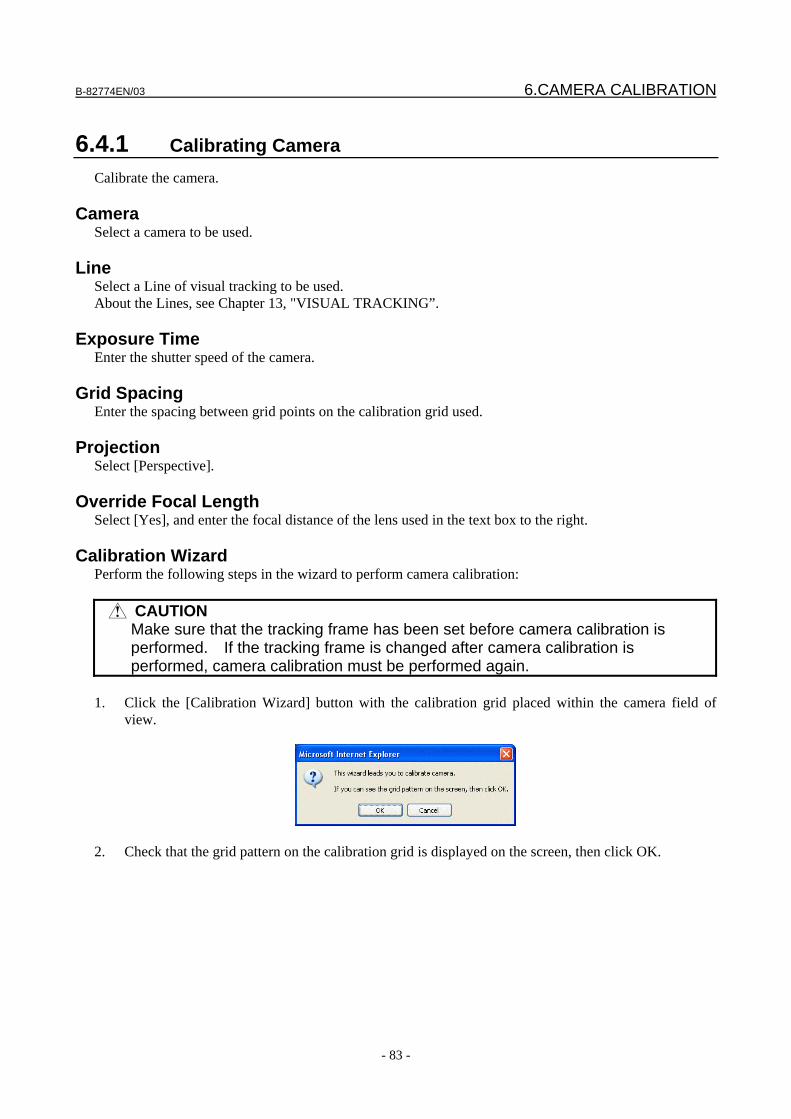
B-82774EN/03 6.CAMERA CALIBRATION
- 83 -
6.4.1 Calibrating Camera Calibrate the camera.
Camera Select a camera to be used.
Line Select a Line of visual tracking to be used. About the Lines, see Chapter 13, "VISUAL TRACKING”.
Exposure Time Enter the shutter speed of the camera.
Grid Spacing Enter the spacing between grid points on the calibration grid used.
Projection Select [Perspective].
Override Focal Length Select [Yes], and enter the focal distance of the lens used in the text box to the right.
Calibration Wizard Perform the following steps in the wizard to perform camera calibration:
CAUTION Make sure that the tracking frame has been set before camera calibration is
performed. If the tracking frame is changed after camera calibration is performed, camera calibration must be performed again.
1. Click the [Calibration Wizard] button with the calibration grid placed within the camera field of
view.
2. Check that the grid pattern on the calibration grid is displayed on the screen, then click OK.
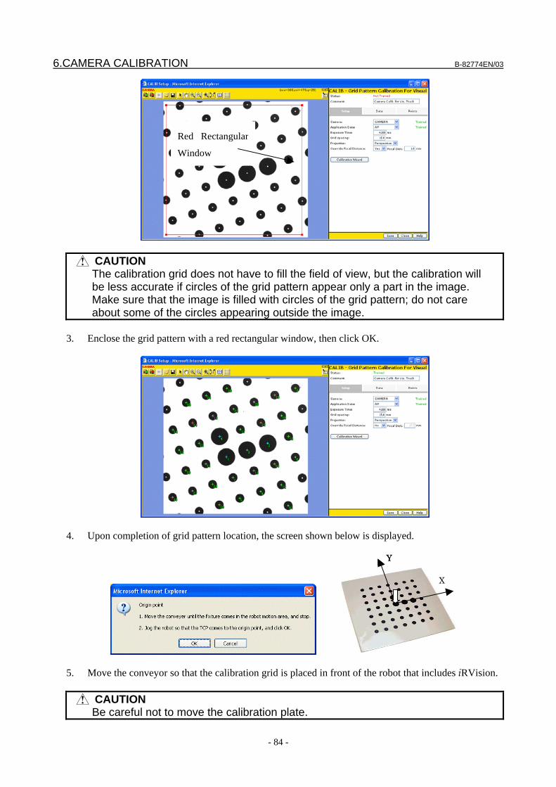
6.CAMERA CALIBRATION B-82774EN/03
- 84 -
CAUTION The calibration grid does not have to fill the field of view, but the calibration will
be less accurate if circles of the grid pattern appear only a part in the image. Make sure that the image is filled with circles of the grid pattern; do not care about some of the circles appearing outside the image.
3. Enclose the grid pattern with a red rectangular window, then click OK.
4. Upon completion of grid pattern location, the screen shown below is displayed.
X
Y
X
Y
5. Move the conveyor so that the calibration grid is placed in front of the robot that includes iRVision.
CAUTION Be careful not to move the calibration plate.
Red Rectangular
Window
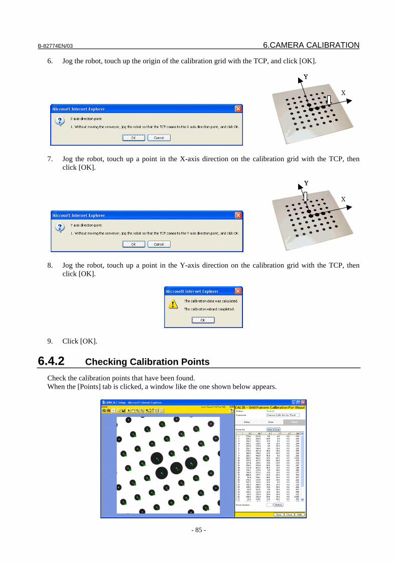
B-82774EN/03 6.CAMERA CALIBRATION
- 85 -
6. Jog the robot, touch up the origin of the calibration grid with the TCP, and click [OK].
X
Y
X
Y
7. Jog the robot, touch up a point in the X-axis direction on the calibration grid with the TCP, then
click [OK].
X
Y
X
Y
8. Jog the robot, touch up a point in the Y-axis direction on the calibration grid with the TCP, then
click [OK].
9. Click [OK].
6.4.2 Checking Calibration Points Check the calibration points that have been found. When the [Points] tab is clicked, a window like the one shown below appears.
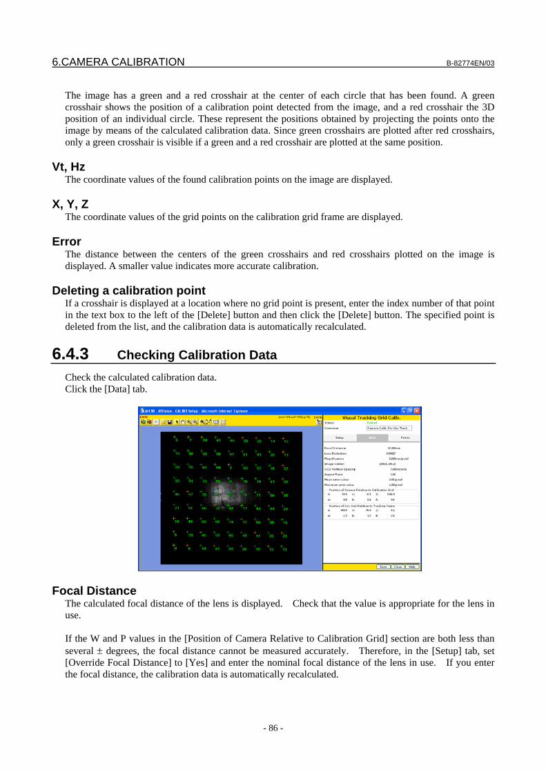
6.CAMERA CALIBRATION B-82774EN/03
- 86 -
The image has a green and a red crosshair at the center of each circle that has been found. A green crosshair shows the position of a calibration point detected from the image, and a red crosshair the 3D position of an individual circle. These represent the positions obtained by projecting the points onto the image by means of the calculated calibration data. Since green crosshairs are plotted after red crosshairs, only a green crosshair is visible if a green and a red crosshair are plotted at the same position.
Vt, Hz The coordinate values of the found calibration points on the image are displayed.
X, Y, Z The coordinate values of the grid points on the calibration grid frame are displayed.
Error The distance between the centers of the green crosshairs and red crosshairs plotted on the image is displayed. A smaller value indicates more accurate calibration.
Deleting a calibration point If a crosshair is displayed at a location where no grid point is present, enter the index number of that point in the text box to the left of the [Delete] button and then click the [Delete] button. The specified point is deleted from the list, and the calibration data is automatically recalculated.
6.4.3 Checking Calibration Data Check the calculated calibration data. Click the [Data] tab.
Focal Distance The calculated focal distance of the lens is displayed. Check that the value is appropriate for the lens in use. If the W and P values in the [Position of Camera Relative to Calibration Grid] section are both less than several ± degrees, the focal distance cannot be measured accurately. Therefore, in the [Setup] tab, set [Override Focal Distance] to [Yes] and enter the nominal focal distance of the lens in use. If you enter the focal distance, the calibration data is automatically recalculated.
B-82774EN/03 6.CAMERA CALIBRATION
- 87 -
Lens Distortion The calculated lens distortion coefficient is displayed. A larger absolute value indicates greater lens distortion. Generally, lenses with shorter focal distances are said to have greater distortion. Grid pattern calibration returns accurate coordinates by using this calculated lens distortion when accurately converting the image frame to the robot frame.
Image Center The coordinates of the center of the image are displayed.
Magnification The size of a pixel in millimeters on the grid pattern plane is displayed. The value indicates how many millimeters are equivalent to a pixel. If the grid pattern plane is not vertical to the optical axis of the camera, the magnification near the center of the image is displayed.
CCD Vertical Spacing The physical size of a pixel of the light receiving element of the camera in use is displayed.
Aspect Ratio The aspect ratio of a pixel of the image is displayed.
Maximum / Average Error The average and maximum errors of each calibration point shown in the [Points] tab table are displayed.
Position of Camera relative to Calibration Grid The position of the camera relative to the calibration grid frame is displayed. For grid frame setting, see Section 12, "CALIBRATION GRID".
6.5 SIMPLE 2D CALIBRATION The simple 2D calibration is intended for compatibility with older versions.
CAUTION The simple 2D calibration has limited functionality, so it is recommended to use
the grid pattern calibration which is easer and more accurate than the simple 2D calibration.
6.CAMERA CALIBRATION B-82774EN/03
- 88 -
Comment A comment added to vision data. Up to 30 one-byte characters or up to 15 two-byte characters can be entered as a comment.
Camera Select the camera you want to calibrate.
Exposure Time Set the exposure time to be applied when camera images are snapped using this window.
Application User Frame Specify the number of a user frame.
Finding calibration points Detect calibration points from the camera image, and set their coordinates on the image. 1. Click the (red) button to snap the camera image.
2. Click the [Find] button for [Calibration point 1]. Enclose the first point within the displayed red
rectangle.
3. Click OK. 4. Similarly, find the circle for [Calibration point 2].
B-82774EN/03 6.CAMERA CALIBRATION
- 89 -
Touching up calibration points Set the coordinates of the calibration points on the robot's user frame. 1. Set the touchup pin on the robot end of arm tooling as the TCP. 2. Jog the robot and touch up the center of calibration point 1 with the TCP. 3. Click [Record] for calibration point 1. 4. Similarly, touch up calibration point 2 and record its position.
Restrictions on simple 2-D calibration The following restrictions are imposed on simple 2-D calibration: • Set the user frame accurately so that the XY plane is parallel to the plane that the workpiece is free
to move in. • Install the camera accurately so that the optical axis is perpendicular to the XY plane of the user
frame. • The Z-axis of the user frame must be oriented to the camera. • Before calibration, set points used for calibration so that they are exactly the same in height as the
workpiece. • If the lens has a short focal distance (e.g. less than 12 mm), lens distortion adversely affects the
offset accuracy. When using a lens having a short focal distance, use grid pattern calibration. • Simple 2-D calibration is not suitable for applications that handle workpieces with different heights.
When there are workpieces with different heights, use grid pattern calibration.

7.VISION PROCESSES B-82774EN/03
- 90 -
7 VISION PROCESSES This chapter explains how to set up vision processes.
7.1 2D SINGLE VIEW VISION PROCESS This is a vision process that detects the two-dimensional position of the workpiece with a single camera, and offsets the robot position.
7.1.1 Setting up a Vision Process If you select [2D Single-view Vision Process] in the tree view, a page like the one shown below appears.
State If all the items have been set, [Trained] is displayed in green. If there is any item yet to be set, [Not Trained] is displayed in red.
B-82774EN/03 7.VISION PROCESSES
- 91 -
Camera Calibration
Select the camera calibration you want to use.
Camera Setup The name of the camera specified for the selected camera calibration is displayed.
Setting the Exposure Time Set the camera's exposure time to be applied when running the vision process. For detailed information about the individual items to be set, see Subsection 4.12.10, “Setting the Exposure”.
Multi-Locator Find mode If you have created more than one locator tool, select how to execute those tools. Find Best
All the locator tools will be executed, and the best result will be chosen. This is effective when you want to identify the type or put location accuracy before processing time.
Find First
The locator tools will be executed sequentially from the top. The location process will stop as soon as the specified number of workpieces have been found. The subsequent locator tools will not be executed. When the results are sorted by score, even if the score of a workpiece found by the locator tool executed first is lower than that of a workpiece found by a locator tool executed subsequently, the result of the locator tool executed first is selected.
Number to Find
Enter the maximum number of workpieces to be found per measurement. The specifiable range is 1 to 100.
Offset Mode Select the robot position offset mode. Fixed Frame Offset
The fixed frame offset data will be calculated. Tool Offset
The tool offset data will be calculated. Found Position
The found position will be output as is, instead of the offset data. This option is provided for any required special offset mode. Do not select it under normal conditions.
Robot Holding the Part
If you have chosen [Tool Offset] for [Offset Mode], specify the robot that is holding the workpiece.
User Tool Number If you have chosen [Tool Offset] for [Offset Mode], specify the tool frame in which you will perform the position offset.
Image Logging Mode Specify whether to save images to the vision log when running the vision process.
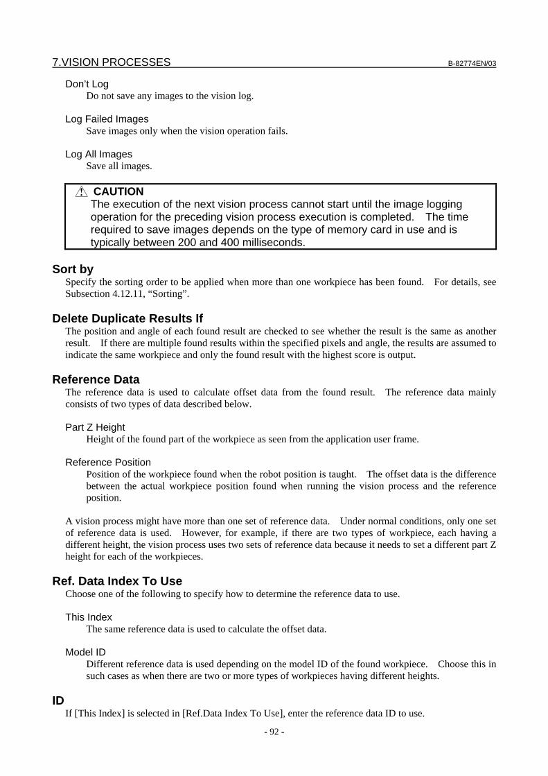
7.VISION PROCESSES B-82774EN/03
- 92 -
Don’t Log Do not save any images to the vision log.
Log Failed Images
Save images only when the vision operation fails. Log All Images
Save all images.
CAUTION The execution of the next vision process cannot start until the image logging
operation for the preceding vision process execution is completed. The time required to save images depends on the type of memory card in use and is typically between 200 and 400 milliseconds.
Sort by
Specify the sorting order to be applied when more than one workpiece has been found. For details, see Subsection 4.12.11, “Sorting”.
Delete Duplicate Results If The position and angle of each found result are checked to see whether the result is the same as another result. If there are multiple found results within the specified pixels and angle, the results are assumed to indicate the same workpiece and only the found result with the highest score is output.
Reference Data The reference data is used to calculate offset data from the found result. The reference data mainly consists of two types of data described below. Part Z Height
Height of the found part of the workpiece as seen from the application user frame. Reference Position
Position of the workpiece found when the robot position is taught. The offset data is the difference between the actual workpiece position found when running the vision process and the reference position.
A vision process might have more than one set of reference data. Under normal conditions, only one set of reference data is used. However, for example, if there are two types of workpiece, each having a different height, the vision process uses two sets of reference data because it needs to set a different part Z height for each of the workpieces.
Ref. Data Index To Use Choose one of the following to specify how to determine the reference data to use. This Index
The same reference data is used to calculate the offset data. Model ID
Different reference data is used depending on the model ID of the found workpiece. Choose this in such cases as when there are two or more types of workpieces having different heights.
ID
If [This Index] is selected in [Ref.Data Index To Use], enter the reference data ID to use.
B-82774EN/03 7.VISION PROCESSES
- 93 -
Adding reference data
You can add reference data as follows. 1. Click the button. 2. In [Model ID], enter the model ID for which to use the reference data.
Deleting reference data
You can delete reference data as follows, if there is more than one set. 1. Select the reference data you want to delete using the index drop-down list 2. Click the button.
Part Z Height Enter the height of the trained features on the workpiece above or below the application user frame.
Reference Position Status If the reference position is set, [Set] is displayed in green; otherwise, [Not Set] is displayed in red.
Reference Position X,Y,R The coordinate values of the set reference position are displayed.
Offset Limit Specify the condition used to check whether the calculated offset value is within the specified range. By default, [None selected] is set, in which case the offset limit check is not made. For information about the offset limit check conditions, see Section 9.2, "OFFSET LIMIT".
7.1.2 Running a Test Test to check whether the tool behaves as expected.
7.VISION PROCESSES B-82774EN/03
- 94 -
Snap and Find button
The tool snaps an image from the camera and attempts to find a workpiece.
Continuous S+F button The tool repeats the Snap and Find operation.
Find button The tool only attempts to find a workpiece without snapping an image. Use this function when you want to confirm the effect of the same image with different location parameters.
Num. Found The number of found workpieces is displayed.
Time to Find The time the location process took is displayed in milliseconds. If you have clicked the [Snap and Find] button, this includes both the time it took to snap the image and the time it took to process it. If you have clicked the [Find] button, this only represents the time it took to process the image and not the time it took to snap it.
Found Result Table
The following values are displayed. X,Y
Coordinate values of the model origin of the found workpiece (units: mm). R
Rotation angle of the found workpiece around the Z axis (units: degrees). Model ID
Model ID of the found workpiece. Score
Score of the found workpiece. Contrast
Contrast of the found workpiece. Fit Error
Elasticity of the found workpiece (units: pixels).
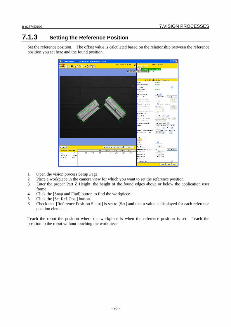
B-82774EN/03 7.VISION PROCESSES
- 95 -
7.1.3 Setting the Reference Position Set the reference position. The offset value is calculated based on the relationship between the reference position you set here and the found position.
1. Open the vision process Setup Page. 2. Place a workpiece in the camera view for which you want to set the reference position. 3. Enter the proper Part Z Height, the height of the found edges above or below the application user
frame. 4. Click the [Snap and Find] button to find the workpiece. 5. Click the [Set Ref. Pos.] button. 6. Check that [Reference Position Status] is set to [Set] and that a value is displayed for each reference
position element. Teach the robot the position where the workpiece is when the reference position is set. Teach the position to the robot without touching the workpiece.

7.VISION PROCESSES B-82774EN/03
- 96 -
7.2 2D MULTI-VIEW VISION PROCESS This is a vision process that detects the two-dimensional position of the workpiece by finding multiple features on different parts of it, and then offsets the robot position. It is effective when the workpiece is too large for the camera to capture its entire image.
In this process, a tool called Camera View is located under the vision process. One camera view corresponds to one measurement point. While the standard number of camera views is two, this number can be increased to a maximum of four.
7.2.1 Setting up a Vision Process If you select [2D Multi-View Vision Process] in the tree view, a window like the one shown below appears.
Status If all of the items have been set, [Trained] is displayed in green. If there is any item yet to be set, [Not Trained] is displayed in red.
Offset Mode Select the robot position offset mode.
B-82774EN/03 7.VISION PROCESSES
- 97 -
Fixed Frame Offset The fixed frame offset data will be calculated.
Tool Offset
The tool offset data will be calculated.
Robot Holding the Part If you have chosen [Tool Offset] in [Offset Mode], specify the robot holding the workpiece.
User Tool Number If you have chosen [Tool Offset] in [Offset Mode], specify the tool frame in which you will perform robot position offset.
Combine Error Limit The combine error limit is the distance the found targets for each camera view move independently of each other. The figure below shows the original found location for each of the three views as the small black targets, and it shows the current found location for each view as the larger target. In the example below there is a combine error, since the relationship between the three targets changed from the original reference position find to the current find, as seen by the size and shape of the triangle changing. If the calculated combine error limit is greater than the user specified limit, the workpiece will not be found. Typically the a sudden increase in the combine error is due to incorrect calibration of one or more of the camera views, or physical changes in the workpiece.
Min. Pos. among pts Allowable minimum distance between measurement points. If the distance between measurement points is shorter than the distance you specify here, an alarm is generated. This item is intended to prevent the robot from receiving an incorrect position offset in case the same workpiece feature is incorrectly found in multiple camera views. Under the normal conditions, the value does not need to be changed.
Image Logging Mode Specify whether to save images to the vision log when running the vision process. Don’t Log
Do not save any images to the vision log. Log Failed Images
Save images only when the vision operation fails. Log All Images
Save all images.
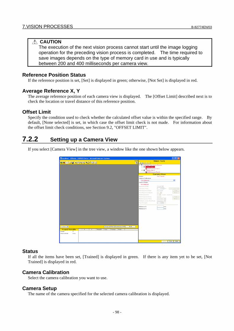
7.VISION PROCESSES B-82774EN/03
- 98 -
CAUTION
The execution of the next vision process cannot start until the image logging operation for the preceding vision process is completed. The time required to save images depends on the type of memory card in use and is typically between 200 and 400 milliseconds per camera view.
Reference Position Status
If the reference position is set, [Set] is displayed in green; otherwise, [Not Set] is displayed in red.
Average Reference X, Y The average reference position of each camera view is displayed. The [Offset Limit] described next is to check the location or travel distance of this reference position.
Offset Limit Specify the condition used to check whether the calculated offset value is within the specified range. By default, [None selected] is set, in which case the offset limit check is not made. For information about the offset limit check conditions, see Section 9.2, "OFFSET LIMIT".
7.2.2 Setting up a Camera View If you select [Camera View] in the tree view, a window like the one shown below appears.
Status If all the items have been set, [Trained] is displayed in green. If there is any item yet to be set, [Not Trained] is displayed in red.
Camera Calibration Select the camera calibration you want to use.
Camera Setup The name of the camera specified for the selected camera calibration is displayed.
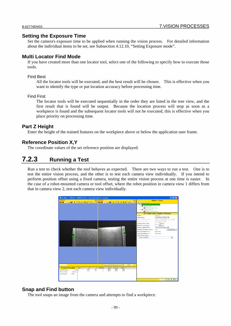
B-82774EN/03 7.VISION PROCESSES
- 99 -
Setting the Exposure Time Set the camera's exposure time to be applied when running the vision process. For detailed information about the individual items to be set, see Subsection 4.12.10, “Setting Exposure mode”.
Multi Locator Find Mode If you have created more than one locator tool, select one of the following to specify how to execute those tools. Find Best
All the locator tools will be executed, and the best result will be chosen. This is effective when you want to identify the type or put location accuracy before processing time.
Find First
The locator tools will be executed sequentially in the order they are listed in the tree view, and the first result that is found will be output. Because the location process will stop as soon as a workpiece is found and the subsequent locator tools will not be executed, this is effective when you place priority on processing time.
Part Z Height
Enter the height of the trained features on the workpiece above or below the application user frame.
Reference Position X,Y The coordinate values of the set reference position are displayed.
7.2.3 Running a Test Run a test to check whether the tool behaves as expected. There are two ways to run a test. One is to test the entire vision process, and the other is to test each camera view individually. If you intend to perform position offset using a fixed camera, testing the entire vision process at one time is easier. In the case of a robot-mounted camera or tool offset, where the robot position in camera view 1 differs from that in camera view 2, test each camera view individually.
Snap and Find button The tool snaps an image from the camera and attempts to find a workpiece.

7.VISION PROCESSES B-82774EN/03
- 100 -
Continuous S+F button The tool repeats the Snap and Find operation.
Find button The tool only attempts to find a workpiece without snapping an image. Use this function when you want to confirm the effect of the same image with different location parameters.
Combine Error Alignment deviation between the point found when the reference position is set and the point found when the test is run (units: mm). This value becomes nearly 0 if there are no differences between workpieces and no location error.
Time to Find The time the location process took is displayed in milliseconds. If you have clicked the [Snap and Find] button, this includes both the time it took to snap the image and the time it took to process it. If you have clicked the [Find] button, this only represents the time it took to process the image and not the time it took to snap it.
Found Result Table The following values are displayed. X,Y
Coordinate values of the model origin of the found workpiece (units: mm). Model ID
Model ID of the found workpiece. Score
Score of the found workpiece. Contrast
Contrast of the found workpiece. Fit Error
Elasticity of the found workpiece (units: pixels).
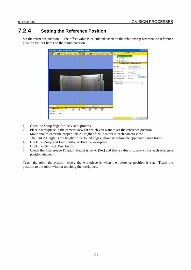
B-82774EN/03 7.VISION PROCESSES
- 101 -
7.2.4 Setting the Reference Position Set the reference position. The offset value is calculated based on the relationship between the reference position you set here and the found position.
1. Open the Setup Page for the vision process. 2. Place a workpiece in the camera view for which you want to set the reference position. 3. Make sure to enter the proper Part Z Height of the locators in each camera view.
The Part Z Height is the height of the found edges, above or below the application user frame. 4. Click the [Snap and Find] button to find the workpiece. 5. Click the [Set. Ref. Pos] button. 6. Check that [Reference Position Status] is set to [Set] and that a value is displayed for each reference
position element. Teach the robot the position where the workpiece is when the reference position is set. Teach the position to the robot without touching the workpiece.
7.VISION PROCESSES B-82774EN/03
- 102 -
7.3 DEPALLETIZING VISION PROCESS The Depalletizing Vision Process is a vision process that performs vertical-direction position offset in addition to the regular two-dimensional position offset. The height of the workpiece is measured based on the apparent size of the workpiece captured by the camera.
7.3.1 Setting up a Vision Process If you select [Depalletizing Vision Process] in the tree view, a window like the one shown below appears.
Status If all the items have been set, [Trained] is displayed in green. If there is any item yet to be set, [Not Trained] is displayed in red.
Camera Calibration Select the camera calibration you want to use.
B-82774EN/03 7.VISION PROCESSES
- 103 -
Camera Setup The name of the camera specified for the selected camera calibration is displayed.
Setting the Exposure Time Setting the exposure time. Set the camera's exposure time to be applied when running the vision process. For detailed information about the individual items to be set, see Subsection 4.12.11, “Setting Exposure Mode”.
Multi Locator Find Mode If you have created more than one locator tool, select how to execute those tools. Find Best
All the locator tools will be executed, and the best result will be chosen. This is effective when you want to identify the type or put location accuracy before processing time.
Find First
The locator tools will be executed sequentially from the top. The location process will stop as soon as the specified number of workpieces have been found. The subsequent locator tools will not be executed. When the results are sorted by score, even if the score of a workpiece found by the locator tool executed first is lower than that of a workpiece found by another locator tool executed subsequently, the result of the locator tool executed first is output.
App. Z Mode
Specify how to calculate the height of the workpiece. Calculate From Found Scale
The Z-direction height of the workpiece will be calculated from the found workpiece size. When [Use layer height] is checked, the number of the layer at which the workpiece is placed is determined from the size of the workpiece found by the vision process. The position of the workpiece is calculated based on the height information corresponding to the layer. The height can be calculated stably even when there is a little size measurement error because the same height information is used for each individual layer. When [Output layer] is checked, the determined layer of the workpiece can be output to the vision register as a measurement value. Specify the number of the measurement value to which to output the tier in [No.].
Use Register Value
The value stored in the specified register of the robot controller will be used as the Z-direction height.
Number to Find
Enter the maximum number of workpieces to be found per measurement. The specifiable range is 1 to 100.
Image Logging Mode Specify whether to save images to the vision log when running the vision process. Don’t Log
Do not save any images to the vision log. Log Failed Image
Save images only when the vision operation fails.
7.VISION PROCESSES B-82774EN/03
- 104 -
Log All Image Save all images.
CAUTION
The execution of the next vision process cannot start until the image logging operation for the preceding vision process execution is completed. The time required to save images depends on the type of memory card in use and is typically between 200 and 400 milliseconds.
Sort by
Specify the sorting order to be applied when more than one workpiece has been found. For details, see Subsection 4.12,11, “Sorting”.
Delete Duplicate Results If The position and angle of each found result is checked to see whether the result is the same as another result. If there are multiple found results within the specified pixels and angle, the results are assumed to indicate the same workpiece and only the found result with the highest score is output.
Reference Data The reference data is used to calculate offset data from the found result. The reference data mainly consists of two types of data described below. App. Z Coordinate
This item is used to determine the Z-direction height of the workpiece. If you have chosen [Use Register Value] in [App Z Mode], specify the number of the register of the robot controller that stores the Z-direction height. If you have chosen [Calculate From Found Size] in [App Z Mode], specify two sets of Z-direction height and size data used as the reference.
Reference Position
Position of the workpiece found when the robot position is taught. The offset data is the difference between the actual workpiece position found when running the vision process and the reference position.
A vision process might have more than one set of reference data. Under normal conditions, only one set of reference data is used. However, for example, if there are two types of workpiece, the vision process uses two sets of reference data because it needs to set the parameters and reference position to determine the Z-direction height for each workpiece.
Adding reference data You can add or delete reference data as follows. 1. Click the button. 2. In [Model ID], enter the model ID for which to use the reference data.
Register Number Use this item when [Use Register Value] is chosen in [App. Z Mode]. Specify the number of the register that stores the workpiece height.
Layer error threshold The layer at which the workpiece is placed is automatically determined based on information of the found size and height corresponding to the reference layer taught in advance. The calculated layer may have a margin of error depending on the found size. Set a value between 1% and 50% as the permissible calculation error in [Layer error threshold]. For example, assume that a value of 20% is specified.
B-82774EN/03 7.VISION PROCESSES
- 105 -
When the height of the workpiece calculated from the found size is within a range between ±20% of the reference height for the layer, the layer is determined. If the height is outside the range, an alarm is issued because the layer cannot be determined.
Setting the Reference Height and Size Use this item when [Calculate From Found Scale] is chosen in [App. Z Mode]. Set the relationship between the actual Z-direction height of the workpiece and the apparent size of the workpiece captured by the camera. 1. Place one workpiece, and touch up the workpiece surface using touch-up pins. Enter this height
data in [Reference Height 1]. 2. Click the [Snap and Find] button to find the workpiece. Then, click the [Set Scale] button and set
[Reference Scale 1]. 3. Place n workpieces, and touch up the workpiece surface using touch-up pins. Enter this height data
in [Reference Height 2]. 4. Click the [Snap and Find] button to find the workpiece. Then, click the [Set Scale] button and set
[Reference Scale 2].
Setting the Reference Layer Use this option when [Use layer height] is checked in [App. Z Mode]. Enter the number of the tier containing the workpiece with which the reference height and size are set.
Reference Position Status If the reference position is set, [Trained] is displayed in green; otherwise, [Not Trained] is displayed in red.
Reference Position X,Y,Z,R The coordinates of the set reference position are displayed.
Offset Limit Specify the condition used to check whether the calculated offset value is within the specified range. By default, [None selected] is set, in which case the offset limit check is not made. For information about the offset limit check conditions, see Section 9.2, "OFFSET LIMIT".
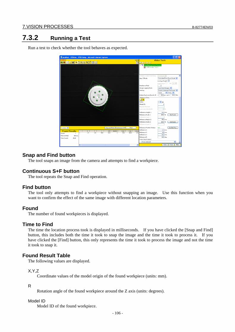
7.VISION PROCESSES B-82774EN/03
- 106 -
7.3.2 Running a Test Run a test to check whether the tool behaves as expected.
Snap and Find button The tool snaps an image from the camera and attempts to find a workpiece.
Continuous S+F button The tool repeats the Snap and Find operation.
Find button The tool only attempts to find a workpiece without snapping an image. Use this function when you want to confirm the effect of the same image with different location parameters.
Found The number of found workpieces is displayed.
Time to Find The time the location process took is displayed in milliseconds. If you have clicked the [Snap and Find] button, this includes both the time it took to snap the image and the time it took to process it. If you have clicked the [Find] button, this only represents the time it took to process the image and not the time it took to snap it.
Found Result Table
The following values are displayed. X,Y,Z
Coordinate values of the model origin of the found workpiece (units: mm). R
Rotation angle of the found workpiece around the Z axis (units: degrees). Model ID
Model ID of the found workpiece.
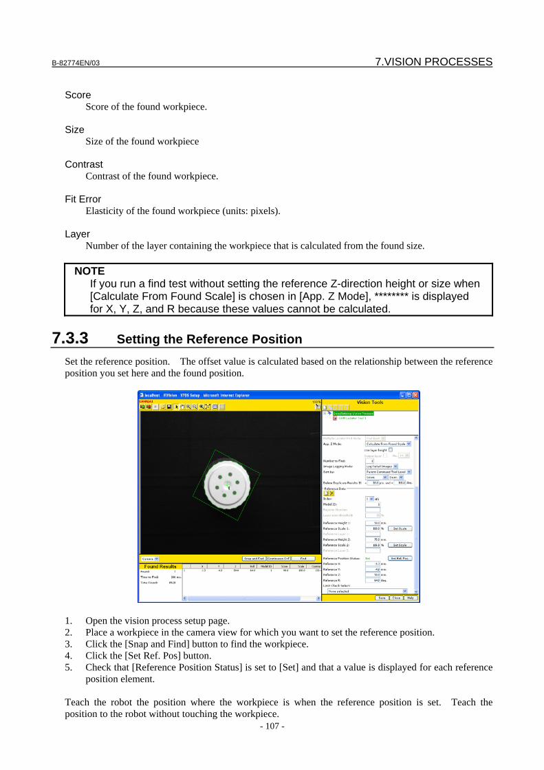
B-82774EN/03 7.VISION PROCESSES
- 107 -
Score
Score of the found workpiece. Size Size of the found workpiece Contrast
Contrast of the found workpiece. Fit Error
Elasticity of the found workpiece (units: pixels). Layer Number of the layer containing the workpiece that is calculated from the found size.
NOTE If you run a find test without setting the reference Z-direction height or size when
[Calculate From Found Scale] is chosen in [App. Z Mode], ******** is displayed for X, Y, Z, and R because these values cannot be calculated.
7.3.3 Setting the Reference Position Set the reference position. The offset value is calculated based on the relationship between the reference position you set here and the found position.
1. Open the vision process setup page. 2. Place a workpiece in the camera view for which you want to set the reference position. 3. Click the [Snap and Find] button to find the workpiece. 4. Click the [Set Ref. Pos] button. 5. Check that [Reference Position Status] is set to [Set] and that a value is displayed for each reference
position element. Teach the robot the position where the workpiece is when the reference position is set. Teach the position to the robot without touching the workpiece.
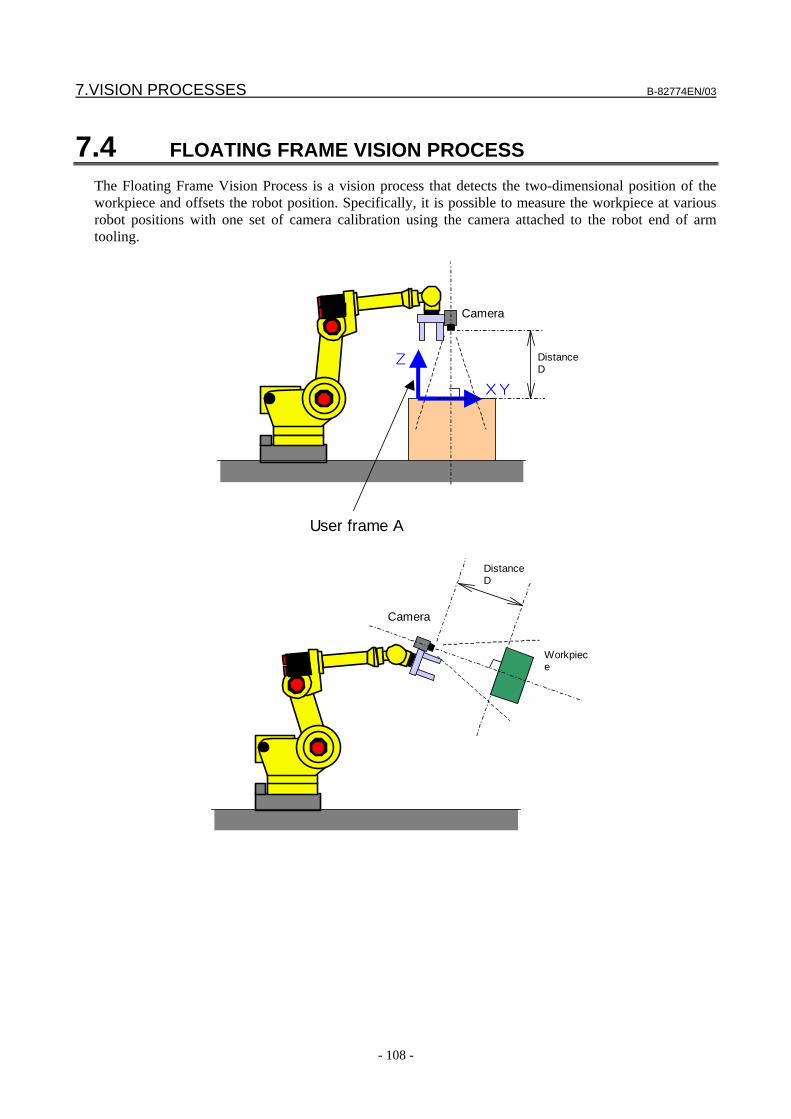
7.VISION PROCESSES B-82774EN/03
- 108 -
7.4 FLOATING FRAME VISION PROCESS The Floating Frame Vision Process is a vision process that detects the two-dimensional position of the workpiece and offsets the robot position. Specifically, it is possible to measure the workpiece at various robot positions with one set of camera calibration using the camera attached to the robot end of arm tooling.
XY
Z
User frame A
Camera
Distance D
Distance D
Camera
Workpiece
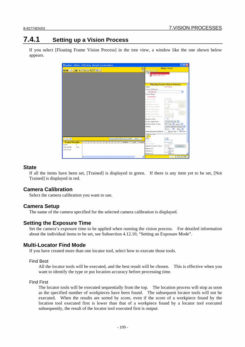
B-82774EN/03 7.VISION PROCESSES
- 109 -
7.4.1 Setting up a Vision Process If you select [Floating Frame Vision Process] in the tree view, a window like the one shown below appears.
State If all the items have been set, [Trained] is displayed in green. If there is any item yet to be set, [Not Trained] is displayed in red.
Camera Calibration Select the camera calibration you want to use.
Camera Setup The name of the camera specified for the selected camera calibration is displayed.
Setting the Exposure Time Set the camera’s exposure time to be applied when running the vision process. For detailed information about the individual items to be set, see Subsection 4.12.10, “Setting an Exposure Mode”.
Multi-Locator Find Mode If you have created more than one locator tool, select how to execute those tools. Find Best
All the locator tools will be executed, and the best result will be chosen. This is effective when you want to identify the type or put location accuracy before processing time.
Find First
The locator tools will be executed sequentially from the top. The location process will stop as soon as the specified number of workpieces have been found. The subsequent locator tools will not be executed. When the results are sorted by score, even if the score of a workpiece found by the location tool executed first is lower than that of a workpiece found by a locator tool executed subsequently, the result of the locator tool executed first is output.
7.VISION PROCESSES B-82774EN/03
- 110 -
Number to Find Enter the maximum number of workpieces to be found per measurement. The specifiable range is 1 to 150.
Image Logging Mode Specify whether to save images to the vision log when running the vision process. Don’t Log
Do not save any images to the vision log. Log Failed Images
Save images only when the vision operation fails. Log All Images
Save all images.
CAUTION The execution of the next vision process cannot start until the image logging
operation for the preceding vision process execution is completed. The time required to save images depends on the type of memory card in use and is typically between 200 and 400 milliseconds.
Ref. Data Index To Use
Choose one of the following to specify how to determine the reference data to use. This Index
The same reference data is used to calculate the offset data. Model ID
Different reference data is used depending on the model ID of the found workpiece. Choose this in such cases as when there are two types of workpieces having different heights.
ID
If [This Index] is selected in [Ref.Data Index To Use], enter the reference data ID to use.
Sort by Specify the sorting order to be applied when more than one workpiece has been found. For details, see Subsection 4.12.11, “Sorting”.
Delete Duplicate Results If The position and angle of each found result are checked to see whether the result is the same as another result. If there are multiple found results within the specified pixels and angle, the results are assumed to indicate the same workpiece and only the found result with the highest score is output.
Reference Data The reference data is used to calculate offset data from the found result. The reference data mainly consists of two types of data described below. Part Z Height
Enter the height of the trained features on the workpiece above or below the application user frame. Reference Position
Position of the workpiece found when the robot position is taught. The offset data is the difference
B-82774EN/03 7.VISION PROCESSES
- 111 -
between the actual workpiece position found when running the vision process and the reference position.
A vision process might have more than one set of reference data. Under normal conditions, only one set of reference data is used. However, for example, if there are two types of workpieces, each having a different height, the vision process uses two sets of reference data because it needs to set a different part Z height for each of the workpieces.
Adding reference data
You can add or delete reference data as follows. 1. Click the button. 2. In [Model ID], enter the model ID for which to use the reference data.
Part Z Height Enter the height of the trained features on the workpiece above or below the application user frame. This is the height of part in the reference position. The reference position part must be in the X/y plane of the application frame.
Reference Position Status If the reference position is set, [Set] is displayed in green; otherwise, [Not Set] is displayed in red.
Reference X, Y, R, W, P, R The coordinates of the set reference position are displayed.
Offset Limit Specify the condition used to check whether the calculated offset value is within the specified range. By default, [None selected] is set, in which case the offset limit check is not made. For information about the offset limit check conditions, see Section 9.2, "OFFSET LIMIT".
7.4.2 Running a Test Test to check whether the tool behaves as expected.
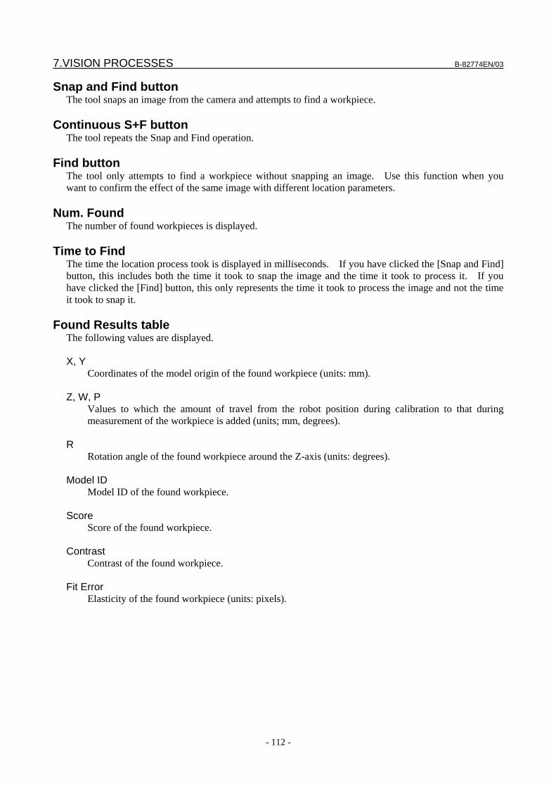
7.VISION PROCESSES B-82774EN/03
- 112 -
Snap and Find button The tool snaps an image from the camera and attempts to find a workpiece.
Continuous S+F button The tool repeats the Snap and Find operation.
Find button The tool only attempts to find a workpiece without snapping an image. Use this function when you want to confirm the effect of the same image with different location parameters.
Num. Found The number of found workpieces is displayed.
Time to Find The time the location process took is displayed in milliseconds. If you have clicked the [Snap and Find] button, this includes both the time it took to snap the image and the time it took to process it. If you have clicked the [Find] button, this only represents the time it took to process the image and not the time it took to snap it.
Found Results table
The following values are displayed. X, Y
Coordinates of the model origin of the found workpiece (units: mm). Z, W, P
Values to which the amount of travel from the robot position during calibration to that during measurement of the workpiece is added (units; mm, degrees).
R
Rotation angle of the found workpiece around the Z-axis (units: degrees). Model ID
Model ID of the found workpiece. Score
Score of the found workpiece. Contrast
Contrast of the found workpiece. Fit Error
Elasticity of the found workpiece (units: pixels).
B-82774EN/03 7.VISION PROCESSES
- 113 -
7.4.3 Setting the Reference Position Set the reference position. The offset value is calculated based on the relationship between the reference position you set here and the found position.
1. Open the vision process Setup Page. 2. Place a workpiece in the camera view for which you want to set the reference position. 3. Enter the height of the reference part above or below the application user frame in the Part Z Height
field 4. Click the [Snap and Find] button to find the workpiece. 5. Click the [Set Ref. Pos.] button. 6. Check that [Reference Position Status] is set to [Set] and that a value is displayed for each reference
position element. Teach the robot the position where the workpiece is when the reference position is set. Teach the position to the robot without touching the workpiece.
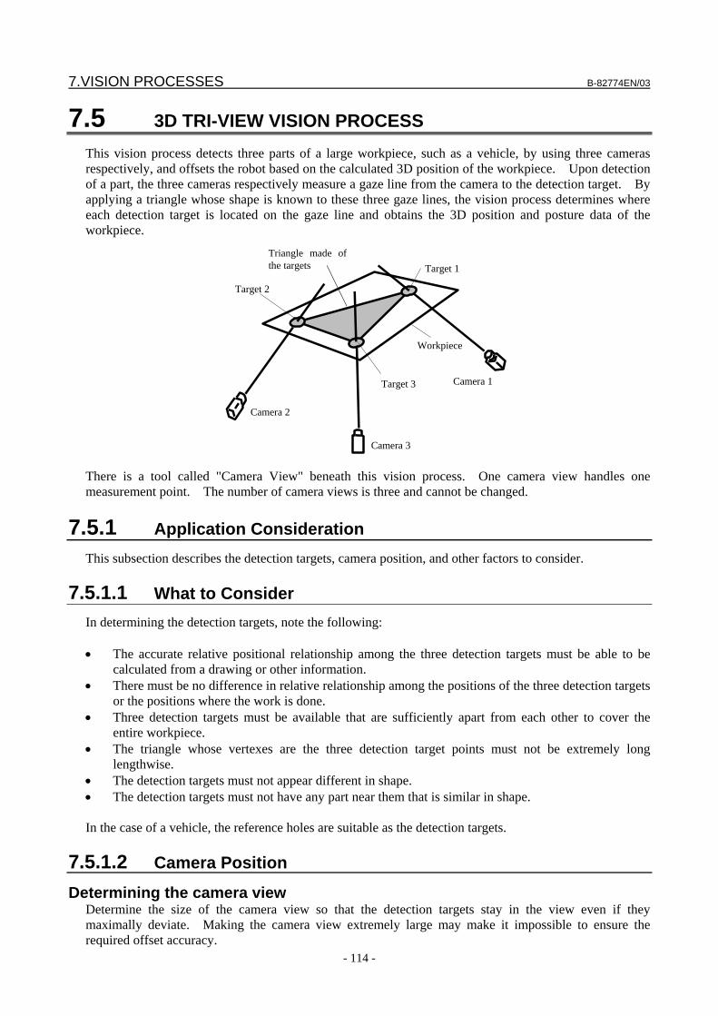
7.VISION PROCESSES B-82774EN/03
- 114 -
7.5 3D TRI-VIEW VISION PROCESS This vision process detects three parts of a large workpiece, such as a vehicle, by using three cameras respectively, and offsets the robot based on the calculated 3D position of the workpiece. Upon detection of a part, the three cameras respectively measure a gaze line from the camera to the detection target. By applying a triangle whose shape is known to these three gaze lines, the vision process determines where each detection target is located on the gaze line and obtains the 3D position and posture data of the workpiece.
Workpiece
Target 1
Target 2
Target 3
Camera 2
Camera 1
Camera 3
Triangle made of the targets
There is a tool called "Camera View" beneath this vision process. One camera view handles one measurement point. The number of camera views is three and cannot be changed.
7.5.1 Application Consideration This subsection describes the detection targets, camera position, and other factors to consider.
7.5.1.1 What to Consider In determining the detection targets, note the following: • The accurate relative positional relationship among the three detection targets must be able to be
calculated from a drawing or other information. • There must be no difference in relative relationship among the positions of the three detection targets
or the positions where the work is done. • Three detection targets must be available that are sufficiently apart from each other to cover the
entire workpiece. • The triangle whose vertexes are the three detection target points must not be extremely long
lengthwise. • The detection targets must not appear different in shape. • The detection targets must not have any part near them that is similar in shape. In the case of a vehicle, the reference holes are suitable as the detection targets.
7.5.1.2 Camera Position
Determining the camera view Determine the size of the camera view so that the detection targets stay in the view even if they maximally deviate. Making the camera view extremely large may make it impossible to ensure the required offset accuracy.
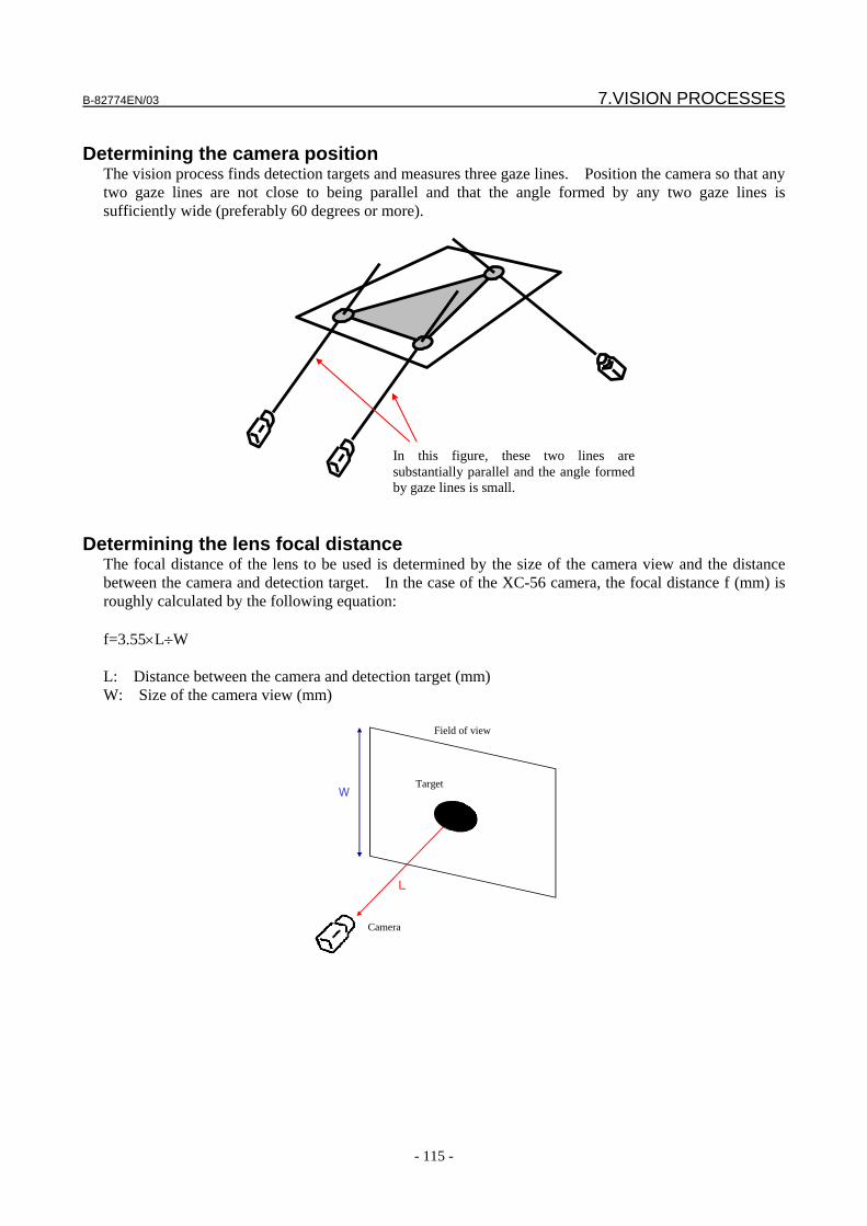
B-82774EN/03 7.VISION PROCESSES
- 115 -
Determining the camera position
The vision process finds detection targets and measures three gaze lines. Position the camera so that any two gaze lines are not close to being parallel and that the angle formed by any two gaze lines is sufficiently wide (preferably 60 degrees or more).
In this figure, these two lines are substantially parallel and the angle formed by gaze lines is small.
Determining the lens focal distance
The focal distance of the lens to be used is determined by the size of the camera view and the distance between the camera and detection target. In the case of the XC-56 camera, the focal distance f (mm) is roughly calculated by the following equation: f=3.55×L÷W L: Distance between the camera and detection target (mm) W: Size of the camera view (mm)
W
L
Camera
Target
Field of view
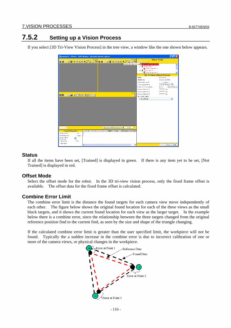
7.VISION PROCESSES B-82774EN/03
- 116 -
7.5.2 Setting up a Vision Process If you select [3D Tri-View Vision Process] in the tree view, a window like the one shown below appears.
Status If all the items have been set, [Trained] is displayed in green. If there is any item yet to be set, [Not Trained] is displayed in red.
Offset Mode Select the offset mode for the robot. In the 3D tri-view vision process, only the fixed frame offset is available. The offset data for the fixed frame offset is calculated.
Combine Error Limit The combine error limit is the distance the found targets for each camera view move independently of each other. The figure below shows the original found location for each of the three views as the small black targets, and it shows the current found location for each view as the larger target. In the example below there is a combine error, since the relationship between the three targets changed from the original reference position find to the current find, as seen by the size and shape of the triangle changing. If the calculated combine error limit is greater than the user specified limit, the workpiece will not be found. Typically the a sudden increase in the combine error is due to incorrect calibration of one or more of the camera views, or physical changes in the workpiece.
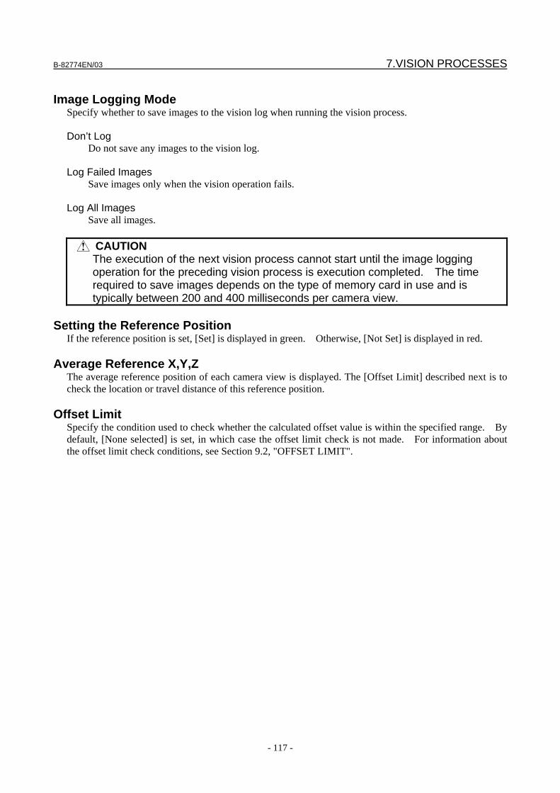
B-82774EN/03 7.VISION PROCESSES
- 117 -
Image Logging Mode
Specify whether to save images to the vision log when running the vision process. Don’t Log
Do not save any images to the vision log. Log Failed Images
Save images only when the vision operation fails. Log All Images
Save all images.
CAUTION The execution of the next vision process cannot start until the image logging
operation for the preceding vision process is execution completed. The time required to save images depends on the type of memory card in use and is typically between 200 and 400 milliseconds per camera view.
Setting the Reference Position
If the reference position is set, [Set] is displayed in green. Otherwise, [Not Set] is displayed in red.
Average Reference X,Y,Z The average reference position of each camera view is displayed. The [Offset Limit] described next is to check the location or travel distance of this reference position.
Offset Limit Specify the condition used to check whether the calculated offset value is within the specified range. By default, [None selected] is set, in which case the offset limit check is not made. For information about the offset limit check conditions, see Section 9.2, "OFFSET LIMIT".
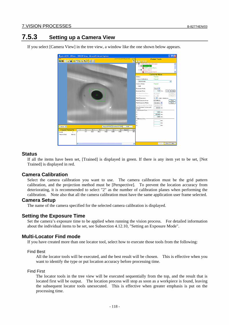
7.VISION PROCESSES B-82774EN/03
- 118 -
7.5.3 Setting up a Camera View If you select [Camera View] in the tree view, a window like the one shown below appears.
Status If all the items have been set, [Trained] is displayed in green. If there is any item yet to be set, [Not Trained] is displayed in red.
Camera Calibration Select the camera calibration you want to use. The camera calibration must be the grid pattern calibration, and the projection method must be [Perspective]. To prevent the location accuracy from deteriorating, it is recommended to select "2" as the number of calibration planes when performing the calibration. Note also that all the camera calibration must have the same application user frame selected.
Camera Setup The name of the camera specified for the selected camera calibration is displayed.
Setting the Exposure Time Set the camera’s exposure time to be applied when running the vision process. For detailed information about the individual items to be set, see Subsection 4.12.10, "Setting an Exposure Mode".
Multi-Locator Find mode If you have created more than one locator tool, select how to execute those tools from the following: Find Best
All the locator tools will be executed, and the best result will be chosen. This is effective when you want to identify the type or put location accuracy before processing time.
Find First
The locator tools in the tree view will be executed sequentially from the top, and the result that is located first will be output. The location process will stop as soon as a workpiece is found, leaving the subsequent locator tools unexecuted. This is effective when greater emphasis is put on the processing time.
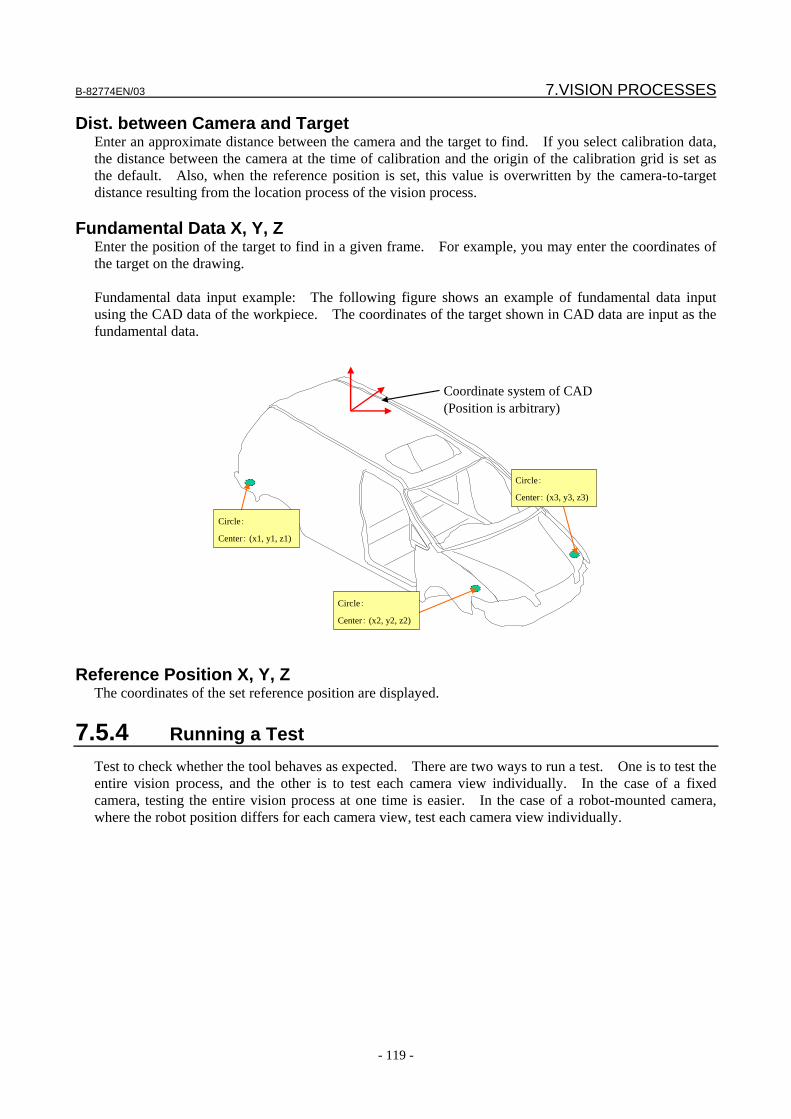
B-82774EN/03 7.VISION PROCESSES
- 119 -
Dist. between Camera and Target Enter an approximate distance between the camera and the target to find. If you select calibration data, the distance between the camera at the time of calibration and the origin of the calibration grid is set as the default. Also, when the reference position is set, this value is overwritten by the camera-to-target distance resulting from the location process of the vision process.
Fundamental Data X, Y, Z Enter the position of the target to find in a given frame. For example, you may enter the coordinates of the target on the drawing. Fundamental data input example: The following figure shows an example of fundamental data input using the CAD data of the workpiece. The coordinates of the target shown in CAD data are input as the fundamental data.
Coordinate system of CAD(Position is arbitrary)
Circle:
Center: (x1, y1, z1)
Circle:
Center: (x2, y2, z2)
Circle:
Center: (x3, y3, z3)
Reference Position X, Y, Z The coordinates of the set reference position are displayed.
7.5.4 Running a Test Test to check whether the tool behaves as expected. There are two ways to run a test. One is to test the entire vision process, and the other is to test each camera view individually. In the case of a fixed camera, testing the entire vision process at one time is easier. In the case of a robot-mounted camera, where the robot position differs for each camera view, test each camera view individually.
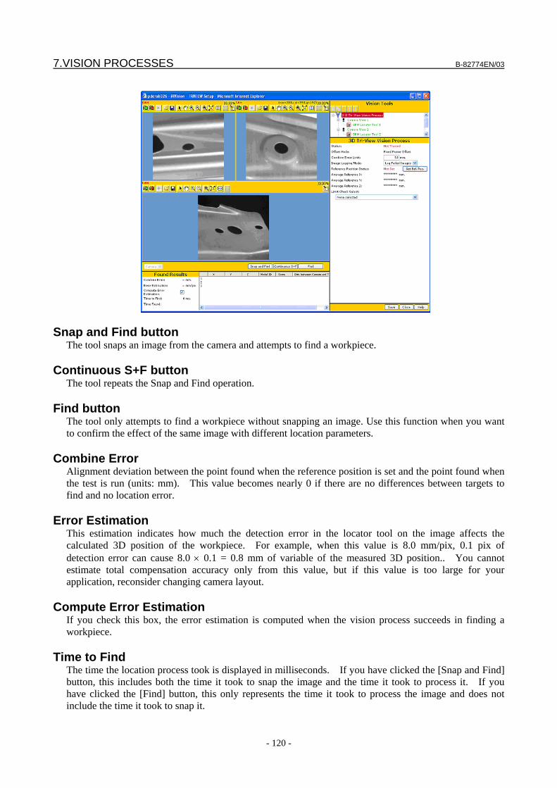
7.VISION PROCESSES B-82774EN/03
- 120 -
Snap and Find button The tool snaps an image from the camera and attempts to find a workpiece.
Continuous S+F button The tool repeats the Snap and Find operation.
Find button The tool only attempts to find a workpiece without snapping an image. Use this function when you want to confirm the effect of the same image with different location parameters.
Combine Error Alignment deviation between the point found when the reference position is set and the point found when the test is run (units: mm). This value becomes nearly 0 if there are no differences between targets to find and no location error.
Error Estimation This estimation indicates how much the detection error in the locator tool on the image affects the calculated 3D position of the workpiece. For example, when this value is 8.0 mm/pix, 0.1 pix of detection error can cause 8.0 × 0.1 = 0.8 mm of variable of the measured 3D position.. You cannot estimate total compensation accuracy only from this value, but if this value is too large for your application, reconsider changing camera layout.
Compute Error Estimation If you check this box, the error estimation is computed when the vision process succeeds in finding a workpiece.
Time to Find The time the location process took is displayed in milliseconds. If you have clicked the [Snap and Find] button, this includes both the time it took to snap the image and the time it took to process it. If you have clicked the [Find] button, this only represents the time it took to process the image and does not include the time it took to snap it.
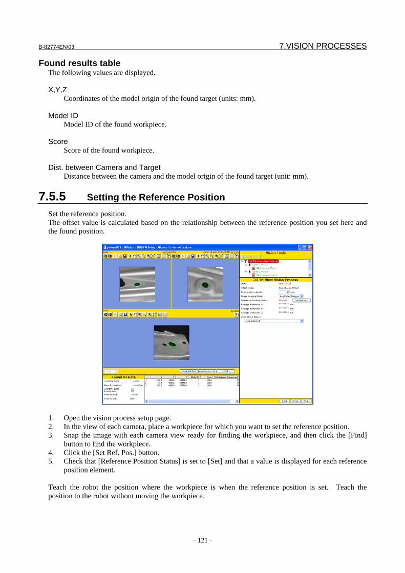
B-82774EN/03 7.VISION PROCESSES
- 121 -
Found results table The following values are displayed. X,Y,Z
Coordinates of the model origin of the found target (units: mm). Model ID
Model ID of the found workpiece. Score
Score of the found workpiece. Dist. between Camera and Target
Distance between the camera and the model origin of the found target (unit: mm).
7.5.5 Setting the Reference Position Set the reference position. The offset value is calculated based on the relationship between the reference position you set here and the found position.
1. Open the vision process setup page. 2. In the view of each camera, place a workpiece for which you want to set the reference position. 3. Snap the image with each camera view ready for finding the workpiece, and then click the [Find]
button to find the workpiece. 4. Click the [Set Ref. Pos.] button. 5. Check that [Reference Position Status] is set to [Set] and that a value is displayed for each reference
position element. Teach the robot the position where the workpiece is when the reference position is set. Teach the position to the robot without moving the workpiece.
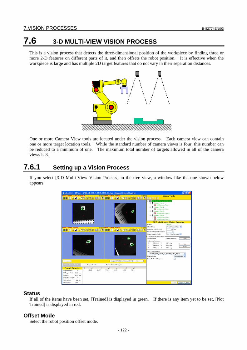
7.VISION PROCESSES B-82774EN/03
- 122 -
7.6 3-D MULTI-VIEW VISION PROCESS This is a vision process that detects the three-dimensional position of the workpiece by finding three or more 2-D features on different parts of it, and then offsets the robot position. It is effective when the workpiece is large and has multiple 2D target features that do not vary in their separation distances.
One or more Camera View tools are located under the vision process. Each camera view can contain one or more target location tools. While the standard number of camera views is four, this number can be reduced to a minimum of one. The maximum total number of targets allowed in all of the camera views is 8.
7.6.1 Setting up a Vision Process If you select [3-D Multi-View Vision Process] in the tree view, a window like the one shown below appears.
Status If all of the items have been set, [Trained] is displayed in green. If there is any item yet to be set, [Not Trained] is displayed in red.
Offset Mode Select the robot position offset mode.
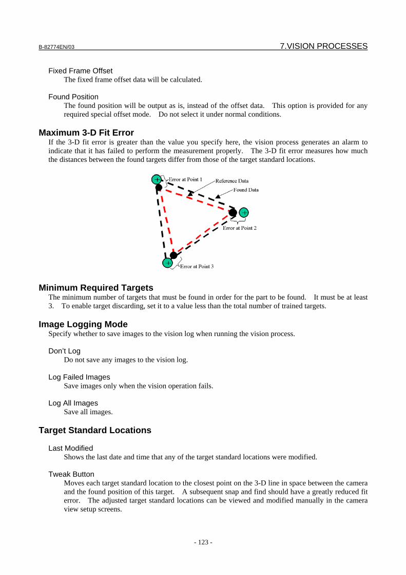
B-82774EN/03 7.VISION PROCESSES
- 123 -
Fixed Frame Offset
The fixed frame offset data will be calculated. Found Position
The found position will be output as is, instead of the offset data. This option is provided for any required special offset mode. Do not select it under normal conditions.
Maximum 3-D Fit Error
If the 3-D fit error is greater than the value you specify here, the vision process generates an alarm to indicate that it has failed to perform the measurement properly. The 3-D fit error measures how much the distances between the found targets differ from those of the target standard locations.
Minimum Required Targets The minimum number of targets that must be found in order for the part to be found. It must be at least 3. To enable target discarding, set it to a value less than the total number of trained targets.
Image Logging Mode Specify whether to save images to the vision log when running the vision process. Don’t Log
Do not save any images to the vision log. Log Failed Images
Save images only when the vision operation fails. Log All Images
Save all images.
Target Standard Locations Last Modified
Shows the last date and time that any of the target standard locations were modified. Tweak Button
Moves each target standard location to the closest point on the 3-D line in space between the camera and the found position of this target. A subsequent snap and find should have a greatly reduced fit error. The adjusted target standard locations can be viewed and modified manually in the camera view setup screens.
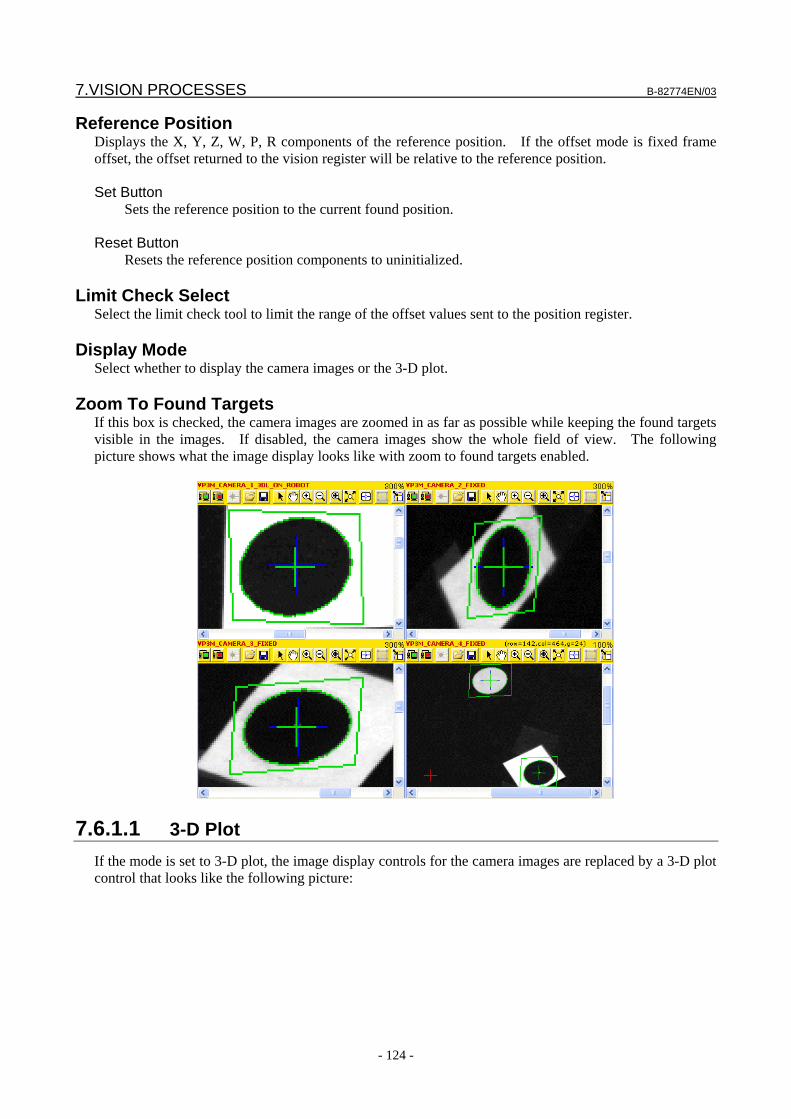
7.VISION PROCESSES B-82774EN/03
- 124 -
Reference Position Displays the X, Y, Z, W, P, R components of the reference position. If the offset mode is fixed frame offset, the offset returned to the vision register will be relative to the reference position. Set Button
Sets the reference position to the current found position. Reset Button
Resets the reference position components to uninitialized.
Limit Check Select Select the limit check tool to limit the range of the offset values sent to the position register.
Display Mode Select whether to display the camera images or the 3-D plot.
Zoom To Found Targets If this box is checked, the camera images are zoomed in as far as possible while keeping the found targets visible in the images. If disabled, the camera images show the whole field of view. The following picture shows what the image display looks like with zoom to found targets enabled.
7.6.1.1 3-D Plot If the mode is set to 3-D plot, the image display controls for the camera images are replaced by a 3-D plot control that looks like the following picture:
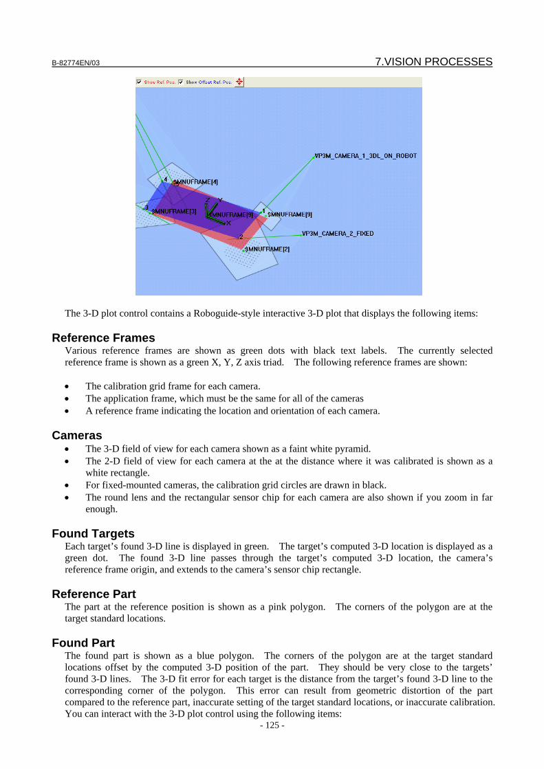
B-82774EN/03 7.VISION PROCESSES
- 125 -
The 3-D plot control contains a Roboguide-style interactive 3-D plot that displays the following items:
Reference Frames Various reference frames are shown as green dots with black text labels. The currently selected reference frame is shown as a green X, Y, Z axis triad. The following reference frames are shown: • The calibration grid frame for each camera. • The application frame, which must be the same for all of the cameras • A reference frame indicating the location and orientation of each camera.
Cameras • The 3-D field of view for each camera shown as a faint white pyramid. • The 2-D field of view for each camera at the at the distance where it was calibrated is shown as a
white rectangle. • For fixed-mounted cameras, the calibration grid circles are drawn in black. • The round lens and the rectangular sensor chip for each camera are also shown if you zoom in far
enough.
Found Targets Each target’s found 3-D line is displayed in green. The target’s computed 3-D location is displayed as a green dot. The found 3-D line passes through the target’s computed 3-D location, the camera’s reference frame origin, and extends to the camera’s sensor chip rectangle.
Reference Part The part at the reference position is shown as a pink polygon. The corners of the polygon are at the target standard locations.
Found Part The found part is shown as a blue polygon. The corners of the polygon are at the target standard locations offset by the computed 3-D position of the part. They should be very close to the targets’ found 3-D lines. The 3-D fit error for each target is the distance from the target’s found 3-D line to the corresponding corner of the polygon. This error can result from geometric distortion of the part compared to the reference part, inaccurate setting of the target standard locations, or inaccurate calibration. You can interact with the 3-D plot control using the following items:

7.VISION PROCESSES B-82774EN/03
- 126 -
Show Ref. Pos.
Check this box to show the pink reference part.
Show Offset Ref. Pos. Check this box to show the blue found part.
Center View Button Click this button to center the view on the selected reference frame.
Mouse Operations The following mouse operations are the same as those in Roboguide: Rotate View
RIGHT Drag rotates the viewing point about the origin of the selected reference frame. Pan View
[CTRL] + RIGHT Drag or CENTER Drag moves the viewing point left, right, up, and down. Zoom in/out
BOTH Drag moves the viewing point towards or away from the center of the display. The remaining mouse operation is similar to the one in Roboguide: Select Reference Frame
LEFT-Click on one of the green dots at the origin of a reference frame to select it. The selected reference frame is shown as a green X, Y, Z axis triad. Centering and rotation take place with respect to the selected reference frame.
7.6.2 Setting up a Camera View If you select [Camera View] in the tree view, a window like the one shown below appears.
B-82774EN/03 7.VISION PROCESSES
- 127 -
Status If all the items have been set, [Trained] is displayed in green. If there is any item yet to be set, [Not Trained] is displayed in red.
Camera Calibration Select the camera calibration tool you want to use.
Camera Setup The name of the camera setup tool associated with the selected camera calibration tool is displayed.
Setting the Auto Exposure and Multi Exposure Settings For detailed information about the individual items to be set, see Subsection 4.12.10, “Setting Exposure mode”.
Target Data There is a set of target data for each target that is trained in the camera view. Must Find This Target
Check this box if this target must be found in order to find the part offset. If the part offset could still be found accurately if this target is missing or discarded, then do not check this box. Note that to find the part offset with fewer than 4 targets, the Minimum Required Targets value in the vision process must be set to 3.
Target Standard Location
The target standard location is the X, Y, Z coordinates of the target. Any reference frame can be used to measure the coordinates, as long as the same frame is used for all of the targets. Two common ways to obtain these coordinates are from dimensional drawings or by using a pointer on the robot with an accurately taught tool frame. The accuracy of the target standard location coordinates is critical to the accuracy of the 3–D part location. If any of the target standard location coordinates are changed, the vision process reference position will be reset and the vision process status will become not trained.
7.6.3 Running a Test Run a test to check whether the tool behaves as expected. There are two ways to run a test. One is to test the entire vision process, and the other is to test each camera view individually. Both the camera view and vision process setup pages have a yellow bar containing the following three buttons:
Snap and Find button The tool snaps an image from the camera and attempts to find a workpiece.
Continuous S+F button The tool repeats the Snap and Find operation.
Find button The tool only attempts to find a workpiece without snapping an image. Use this function when you want to try different location parameters the same image.
7.6.3.1 Camera View Found Results The camera view found results frame resembles the following picture:
7.VISION PROCESSES B-82774EN/03
- 128 -
Found The number of targets that were found.
Time to Find The time the location process took is displayed in milliseconds. If you have clicked the [Snap and Find] button, this includes both the time it took to snap the image and the time it took to process it. If you have clicked the [Find] button, this only represents the time it took to process the image and not the time it took to snap it.
Found Result Table The following values are displayed for each found target: Location Tool
The name of the location tool that found this target result. Row, Column
2-D coordinate values of the model origin of the found target (units: pixels). X,Y,Z
3-D Coordinate values of the model origin of the found target, calculated from all of the targets in all of the camera views (units: mm).
Score
The score of the found target.
7.6.3.2 Vision Process Found Results The vision process found results tab resembles the following picture:
Targets Found The number of targets that were found.
All Target Fit Err. The original 3-D fit error including all found targets.
Fit Error The 3-D fit error excluding the discarded target, if any.
Discarded Target The target that was discarded, if any.
B-82774EN/03 7.VISION PROCESSES
- 129 -
Time to Find The time the location process took is displayed in milliseconds. If you have clicked the [Snap and Find] button, this includes both the time it took to snap the images and the time it took to process them. If you have clicked the [Find] button, this only represents the time it took to process the images and not the time it took to snap them.
Time Found The time when the part was found.
Found Result Table X, Y, Z, W, P, R components of the found part position are displayed.
7.6.3.3 Vision Process Target Results The vision process target results tab resembles the following picture:
Found Result Table The following values are displayed for each found target: C.V.
The camera view that found this target result. Location Tool
The name of the location tool that found this target result. Status
The status of this target: either Found, Not Found, or Discarded. Score
The score of the found target. 3-D Fit Err.
The 3-D fit error of this individual target. This is the distance between the computed (X, Y, Z) location of this target and the 3-D line from the camera to the found position of this target.
Row Shift, Col. Shift
The offset in pixels of this target relative to its standard location. X Shift, Y Shift, Z Shift
The (X, Y, Z) offset of this individual target relative to its standard location.
7.6.3.4 Vision Process Target Discard Analysis If more than the minimum number of targets is found and the fit error exceeds the maximum, the software attempts to identify which target is bad. The bad target is discarded and the offset is computed with the remaining targets. Determining which target is bad is difficult to do if only 4 targets are found. The software provides seven candidate score functions to help identify the bad target. The scores for each target are shown in the table. The score functions can be enabled individually or in any combination using the check boxes in the left column of the table. If 5 or more targets are found, identifying the bad
7.VISION PROCESSES B-82774EN/03
- 130 -
target is easy. The first score function in the list picks the target that reduces the fit error the most when it is discarded. However, if only 4 targets are found, the fit error with one target eliminated is usually zero and this score function is not helpful. The vision process target discard analysis tab resembles the following picture:
3-D Fit Error Without This Target
This is the fit error computed with this target discarded. This value is usually very small. The target which when discarded results in the smallest fit error is discarded.
Target Locator Score
This is the score value computed by the location tool for this target. The target with the lowest score is discarded.
Target Offset in Pixels
This is the magnitude of the pixel offset for this particular target relative to the standard location. The target with the largest shift is discarded.
XYZ Shift Without This Target
This value is computed with this target discarded. It is the magnitude of the 3-D shift relative to the standard location. The target which when discarded results in the smallest shift is discarded.
3-D Rotation Without This Target
This value is computed with this target discarded. It is the total 3-D angle relative to the standard location. The target which when discarded results in the smallest angle is discarded.
Z Shift From Original W/O Target
This value is computed with this target discarded. It is the magnitude of the 3-D shift relative to that computed by the original solution. The target which when discarded results in the smallest shift is discarded.
3-D Rotation From Original W/O Target
This value is computed using the 3-camera solution with this target discarded. It is the total 3-D angle relative to that computed by the original solution. The target which when discarded results in the smallest angle is discarded.
7.6.4 Setting the Reference Position Set the reference position. The offset value is calculated based on the relationship between the reference position you set here and the found position. 1. Open the Setup Page for the vision process. 2. Place a workpiece in the camera view for which you want to set the reference position. 3. Click the [Snap and Find] button to find the workpiece. 4. Click the [Set] button in the Reference Position section.
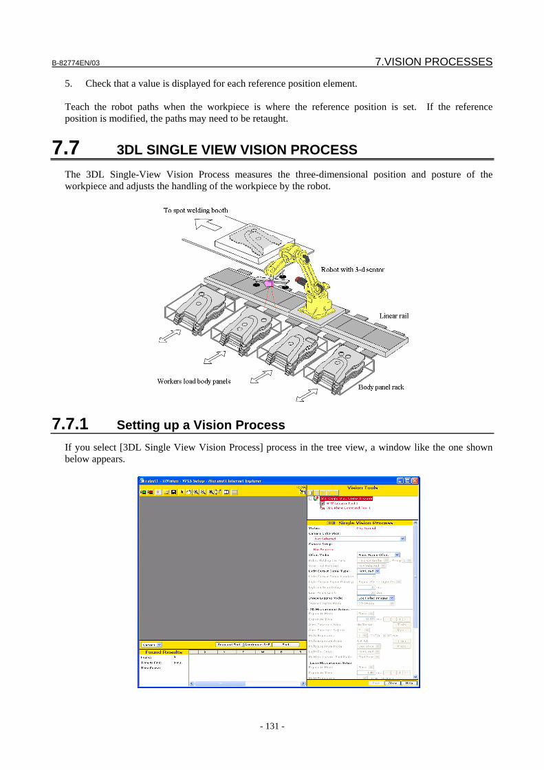
B-82774EN/03 7.VISION PROCESSES
- 131 -
5. Check that a value is displayed for each reference position element. Teach the robot paths when the workpiece is where the reference position is set. If the reference position is modified, the paths may need to be retaught.
7.7 3DL SINGLE VIEW VISION PROCESS The 3DL Single-View Vision Process measures the three-dimensional position and posture of the workpiece and adjusts the handling of the workpiece by the robot.
7.7.1 Setting up a Vision Process If you select [3DL Single View Vision Process] process in the tree view, a window like the one shown below appears.
7.VISION PROCESSES B-82774EN/03
- 132 -
Status If all the items have been set, [Trained] is displayed in green. If there is any item yet to be set, [Not Trained] is displayed in red.
Camera Calibration Select the camera calibration you want to use.
Camera Setup The name of the camera specified for the selected camera calibration is displayed.
Offset Mode Select the robot position offset mode. Fixed Frame Offset
The fixed frame offset data will be calculated. Tool Offset
The tool offset data will be calculated. Found Position (User)
The found position will be output as is, instead of the offset data. This option is provided for any required specified offset mode. Do not select it under normal conditions. The found position is relative to the application user frame.
Found Position (Tool) The found position will be output, instead of the offset data, after being converted to a value as seen from the tool frame. This option is provided for any required specified offset mode. Do not select it under normal conditions
Robot Holding Part
If you have chosen [Tool Offset] or [Found Position (Tool)] for [Offset Type], specify the robot holding the workpiece.
User Tool Number If you have chosen [Tool Offset] or [Found Position (Tool)] in [Offset Type], specify the user tool in which you will perform position offset.
Setting the Light Use this function to have an external light turned on or off as appropriate for the vision process executed with the 3D laser sensor. By using this function, you can have the light turned on, for example, when finding two-dimensional features during one three-dimensional measurement, or have it turned off when finding the two laser lines. It is common to have an LED ring light mounted to the 3D laser sensor to provide controlled lighting. Set the function as follows. 1. In [Light Output Signal Type], specify the type of signal - DO or RO - that turns on or off the light. 2. In [Light Output Signal Number], enter the number of the output point to which the ON/OFF signal
is connected. For example, when connecting the signal to RO[1], enter 1. 3. In [Light Output Signal Polarity], set the relationship between the signal output and turning on or off
the light. To turn on the light when the signal is ON, set [Signal=ON->Light=ON]. To turn it off when the signal is ON, set [Signal=OFF->Light=ON].
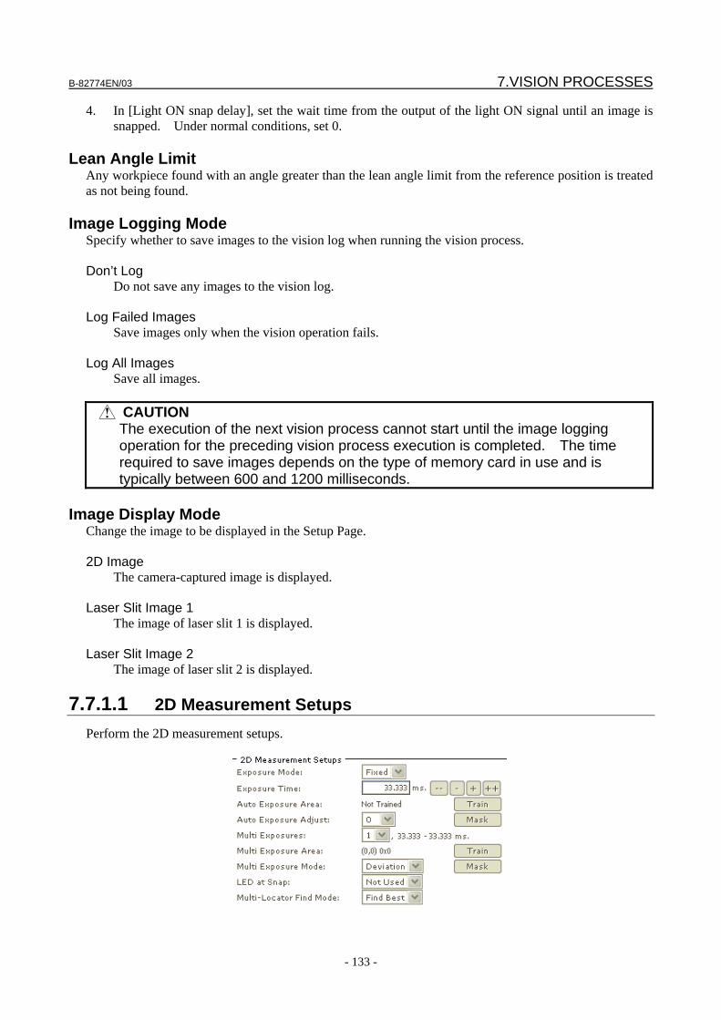
B-82774EN/03 7.VISION PROCESSES
- 133 -
4. In [Light ON snap delay], set the wait time from the output of the light ON signal until an image is snapped. Under normal conditions, set 0.
Lean Angle Limit
Any workpiece found with an angle greater than the lean angle limit from the reference position is treated as not being found.
Image Logging Mode Specify whether to save images to the vision log when running the vision process. Don’t Log
Do not save any images to the vision log. Log Failed Images
Save images only when the vision operation fails. Log All Images
Save all images.
CAUTION The execution of the next vision process cannot start until the image logging
operation for the preceding vision process execution is completed. The time required to save images depends on the type of memory card in use and is typically between 600 and 1200 milliseconds.
Image Display Mode
Change the image to be displayed in the Setup Page. 2D Image
The camera-captured image is displayed. Laser Slit Image 1
The image of laser slit 1 is displayed. Laser Slit Image 2
The image of laser slit 2 is displayed.
7.7.1.1 2D Measurement Setups Perform the 2D measurement setups.
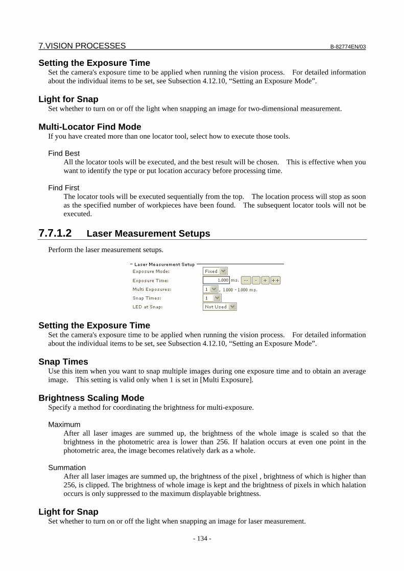
7.VISION PROCESSES B-82774EN/03
- 134 -
Setting the Exposure Time Set the camera's exposure time to be applied when running the vision process. For detailed information about the individual items to be set, see Subsection 4.12.10, “Setting an Exposure Mode”.
Light for Snap Set whether to turn on or off the light when snapping an image for two-dimensional measurement.
Multi-Locator Find Mode If you have created more than one locator tool, select how to execute those tools. Find Best
All the locator tools will be executed, and the best result will be chosen. This is effective when you want to identify the type or put location accuracy before processing time.
Find First
The locator tools will be executed sequentially from the top. The location process will stop as soon as the specified number of workpieces have been found. The subsequent locator tools will not be executed.
7.7.1.2 Laser Measurement Setups
Perform the laser measurement setups.
Setting the Exposure Time Set the camera's exposure time to be applied when running the vision process. For detailed information about the individual items to be set, see Subsection 4.12.10, “Setting an Exposure Mode”.
Snap Times Use this item when you want to snap multiple images during one exposure time and to obtain an average image. This setting is valid only when 1 is set in [Multi Exposure].
Brightness Scaling Mode Specify a method for coordinating the brightness for multi-exposure. Maximum
After all laser images are summed up, the brightness of the whole image is scaled so that the brightness in the photometric area is lower than 256. If halation occurs at even one point in the photometric area, the image becomes relatively dark as a whole.
Summation
After all laser images are summed up, the brightness of the pixel , brightness of which is higher than 256, is clipped. The brightness of whole image is kept and the brightness of pixels in which halation occurs is only suppressed to the maximum displayable brightness.
Light for Snap
Set whether to turn on or off the light when snapping an image for laser measurement.

B-82774EN/03 7.VISION PROCESSES
- 135 -
TIP If more than one laser measurement tool, such as 3DL plane command tool or
3DL displacement command tool, has been created, the tools will be executed sequentially from the top, and the measurement process will stop as soon as a measurement succeeds, leaving the subsequent tools unexecuted.
7.7.1.3 Reference Data
Set the reference data.
Reference Position Status If the reference position is set, [Set] is displayed in green; otherwise, [Not Set] is displayed in red.
Reference Position X,Y,Z,W,P,R The coordinate values of the set reference position are displayed.
Offset Limit Specify the condition used to check whether the calculated offset value is within the specified range. By default, [None selected] is set, in which case the offset limit check is not made. For information about the offset limit check conditions, see Section 9.2, "OFFSET LIMIT".
7.7.2 Running a Test Run a test to check whether the tool behaves as expected.
Snap and Find button The tool snaps an image from the camera and attempts to find a workpiece.
Continuous S+F button The tool repeats the Snap and Find operation.
Find button The tool only attempts to find a workpiece without snapping an image. Use this function when you want to confirm the effect of the same image with different location parameters.
Found The number of found workpieces is displayed.
Time to Find The time the location process took is displayed in milliseconds. If you have clicked the [Snap and Find] button, this includes both the time it took to snap the image and the time it took to process it. If you
7.VISION PROCESSES B-82774EN/03
- 136 -
have clicked the [Find] button, this only represents the time it took to process the image and not the time it took to snap it.
Found Result Table
The following values are displayed. X,Y,Z
Coordinate values of the model origin of the found workpiece (units: mm). W,P,R
Rotation angle of the found workpiece around the X, Y, and Z axis (units: degrees). Laser ID
Laser measurement ID of the found workpiece. Model ID
Model ID of the found workpiece. Score
Score of the found workpiece. Contrast
Contrast of the found workpiece. Fit Error
Elasticity of the found workpiece (units: pixels). Lean Angle
Inclination angle of the found workpiece (units: degrees).
7.7.3 Setting the Reference Position Set the reference position. The offset value is calculated based on the relationship between the reference position you set here and the found position. 1. Open the Setup Page for the vision process. 2. Place a workpiece in the camera view for which you want to set the reference position. 3. Click the [Snap and Find] button to find the workpiece. 4. Click the [Set Ref. Pos.] button. 5. Check that [Reference Position Status] is set to [Set] and that a value is displayed for each reference
position element. Teach the robot the position where the workpiece is when the reference position is set. Teach the position to the robot without touching the workpiece.
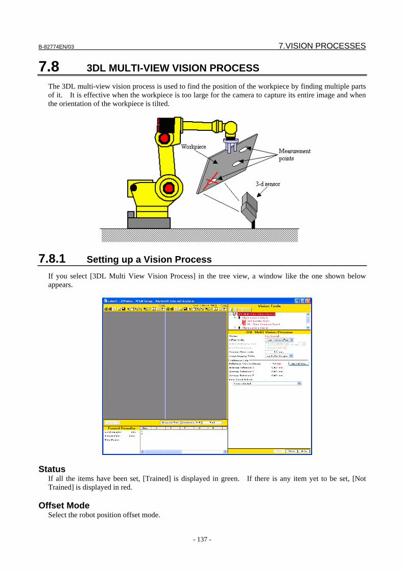
B-82774EN/03 7.VISION PROCESSES
- 137 -
7.8 3DL MULTI-VIEW VISION PROCESS The 3DL multi-view vision process is used to find the position of the workpiece by finding multiple parts of it. It is effective when the workpiece is too large for the camera to capture its entire image and when the orientation of the workpiece is tilted.
7.8.1 Setting up a Vision Process If you select [3DL Multi View Vision Process] in the tree view, a window like the one shown below appears.
Status If all the items have been set, [Trained] is displayed in green. If there is any item yet to be set, [Not Trained] is displayed in red.
Offset Mode Select the robot position offset mode.
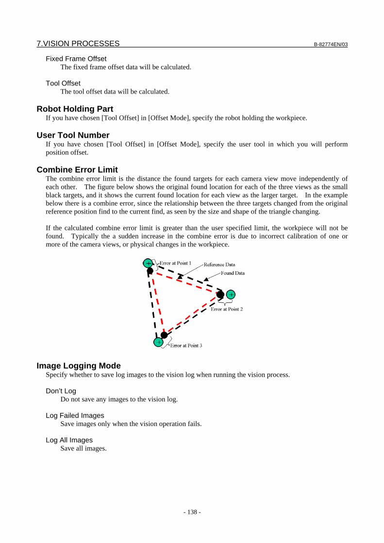
7.VISION PROCESSES B-82774EN/03
- 138 -
Fixed Frame Offset The fixed frame offset data will be calculated.
Tool Offset
The tool offset data will be calculated.
Robot Holding Part If you have chosen [Tool Offset] in [Offset Mode], specify the robot holding the workpiece.
User Tool Number If you have chosen [Tool Offset] in [Offset Mode], specify the user tool in which you will perform position offset.
Combine Error Limit The combine error limit is the distance the found targets for each camera view move independently of each other. The figure below shows the original found location for each of the three views as the small black targets, and it shows the current found location for each view as the larger target. In the example below there is a combine error, since the relationship between the three targets changed from the original reference position find to the current find, as seen by the size and shape of the triangle changing. If the calculated combine error limit is greater than the user specified limit, the workpiece will not be found. Typically the a sudden increase in the combine error is due to incorrect calibration of one or more of the camera views, or physical changes in the workpiece.
Image Logging Mode Specify whether to save log images to the vision log when running the vision process. Don’t Log
Do not save any images to the vision log. Log Failed Images
Save images only when the vision operation fails. Log All Images
Save all images.
B-82774EN/03 7.VISION PROCESSES
- 139 -
CAUTION The execution of the next vision process cannot start until the image logging
operation for the preceding vision process execution is completed. The time required to save images depends on the type of memory card in use and is typically between 600 and 1200 milliseconds per camera view.
Reference Position Status
If the reference position is set, [Trained] is displayed in green; otherwise, [Not Trained] is displayed in red.
Average Reference X, Y, Z The average reference position of each camera view is displayed. The offset limit check described next is to check the location or travel distance of this reference position.
Offset Limit Specify the condition used to check whether the calculated offset value is within the specified range. By default, [None selected] is set, in which case the offset limit check is not made. For information about the offset limit check conditions, see Section 9.2, "OFFSET LIMIT".
7.8.2 Setting up a Camera View If you select [Plane Camera View] in the tree view, a window like the one shown below appears.
Status If all the items have been set, [Trained] is displayed in green. If there is any item yet to be set, [Not Trained] is displayed in red.
Camera Calibration Select the camera calibration you want to use.
Camera Setup The name of the camera specified for the selected camera calibration is displayed.
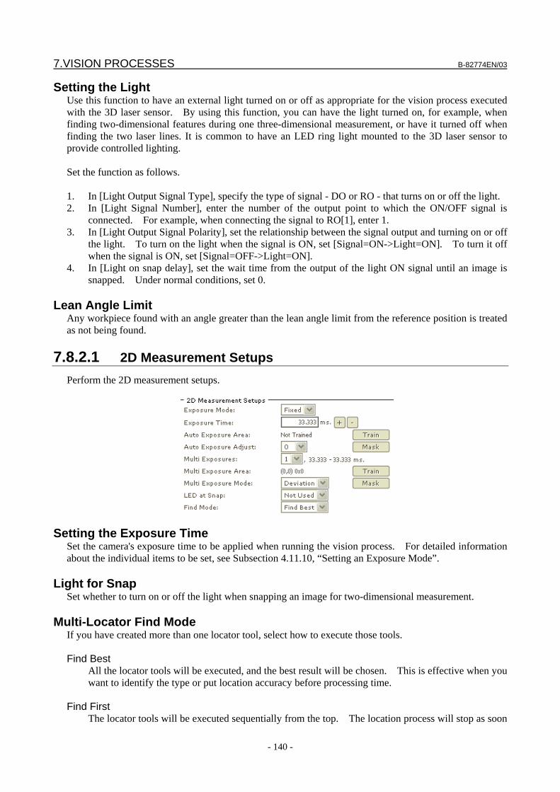
7.VISION PROCESSES B-82774EN/03
- 140 -
Setting the Light Use this function to have an external light turned on or off as appropriate for the vision process executed with the 3D laser sensor. By using this function, you can have the light turned on, for example, when finding two-dimensional features during one three-dimensional measurement, or have it turned off when finding the two laser lines. It is common to have an LED ring light mounted to the 3D laser sensor to provide controlled lighting. Set the function as follows. 1. In [Light Output Signal Type], specify the type of signal - DO or RO - that turns on or off the light. 2. In [Light Signal Number], enter the number of the output point to which the ON/OFF signal is
connected. For example, when connecting the signal to RO[1], enter 1. 3. In [Light Output Signal Polarity], set the relationship between the signal output and turning on or off
the light. To turn on the light when the signal is ON, set [Signal=ON->Light=ON]. To turn it off when the signal is ON, set [Signal=OFF->Light=ON].
4. In [Light on snap delay], set the wait time from the output of the light ON signal until an image is snapped. Under normal conditions, set 0.
Lean Angle Limit
Any workpiece found with an angle greater than the lean angle limit from the reference position is treated as not being found.
7.8.2.1 2D Measurement Setups Perform the 2D measurement setups.
Setting the Exposure Time Set the camera's exposure time to be applied when running the vision process. For detailed information about the individual items to be set, see Subsection 4.11.10, “Setting an Exposure Mode”.
Light for Snap Set whether to turn on or off the light when snapping an image for two-dimensional measurement.
Multi-Locator Find Mode If you have created more than one locator tool, select how to execute those tools. Find Best
All the locator tools will be executed, and the best result will be chosen. This is effective when you want to identify the type or put location accuracy before processing time.
Find First
The locator tools will be executed sequentially from the top. The location process will stop as soon
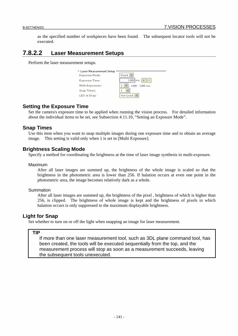
B-82774EN/03 7.VISION PROCESSES
- 141 -
as the specified number of workpieces have been found. The subsequent locator tools will not be executed.
7.8.2.2 Laser Measurement Setups
Perform the laser measurement setups.
Setting the Exposure Time Set the camera's exposure time to be applied when running the vision process. For detailed information about the individual items to be set, see Subsection 4.11.10, “Setting an Exposure Mode”.
Snap Times Use this item when you want to snap multiple images during one exposure time and to obtain an average image. This setting is valid only when 1 is set in [Multi Exposure].
Brightness Scaling Mode Specify a method for coordinating the brightness at the time of laser image synthesis in multi-exposure. Maximum After all laser images are summed up, the brightness of the whole image is scaled so that the
brightness in the photometric area is lower than 256. If halation occurs at even one point in the photometric area, the image becomes relatively dark as a whole.
Summation
After all laser images are summed up, the brightness of the pixel , brightness of which is higher than 256, is clipped. The brightness of whole image is kept and the brightness of pixels in which halation occurs is only suppressed to the maximum displayable brightness.
Light for Snap
Set whether to turn on or off the light when snapping an image for laser measurement.
TIP If more than one laser measurement tool, such as 3DL plane command tool, has
been created, the tools will be executed sequentially from the top, and the measurement process will stop as soon as a measurement succeeds, leaving the subsequent tools unexecuted.
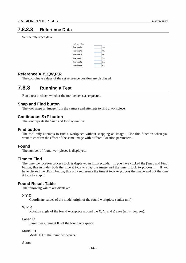
7.VISION PROCESSES B-82774EN/03
- 142 -
7.8.2.3 Reference Data Set the reference data.
Reference X,Y,Z,W,P,R The coordinate values of the set reference position are displayed.
7.8.3 Running a Test Run a test to check whether the tool behaves as expected.
Snap and Find button The tool snaps an image from the camera and attempts to find a workpiece.
Continuous S+F button The tool repeats the Snap and Find operation.
Find button The tool only attempts to find a workpiece without snapping an image. Use this function when you want to confirm the effect of the same image with different location parameters.
Found The number of found workpieces is displayed.
Time to Find The time the location process took is displayed in milliseconds. If you have clicked the [Snap and Find] button, this includes both the time it took to snap the image and the time it took to process it. If you have clicked the [Find] button, this only represents the time it took to process the image and not the time it took to snap it.
Found Result Table
The following values are displayed.
X,Y,Z Coordinate values of the model origin of the found workpiece (units: mm).
W,P,R Rotation angle of the found workpiece around the X, Y, and Z axes (units: degrees). Laser ID
Laser measurement ID of the found workpiece. Model ID Model ID of the found workpiece.
Score
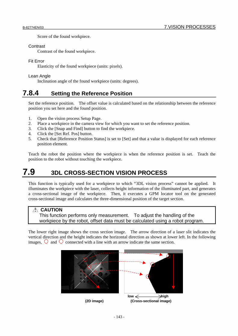
B-82774EN/03 7.VISION PROCESSES
- 143 -
Score of the found workpiece.
Contrast Contrast of the found workpiece.
Fit Error Elasticity of the found workpiece (units: pixels).
Lean Angle Inclination angle of the found workpiece (units: degrees).
7.8.4 Setting the Reference Position Set the reference position. The offset value is calculated based on the relationship between the reference position you set here and the found position. 1. Open the vision process Setup Page. 2. Place a workpiece in the camera view for which you want to set the reference position. 3. Click the [Snap and Find] button to find the workpiece. 4. Click the [Set Ref. Pos] button. 5. Check that [Reference Position Status] is set to [Set] and that a value is displayed for each reference
position element. Teach the robot the position where the workpiece is when the reference position is set. Teach the position to the robot without touching the workpiece.
7.9 3DL CROSS-SECTION VISION PROCESS This function is typically used for a workpiece to which “3DL vision process” cannot be applied. It illuminates the workpiece with the laser, collects height information of the illuminated part, and generates a cross-sectional image of the workpiece. Then, it executes a GPM locator tool on the generated cross-sectional image and calculates the three-dimensional position of the target section.
CAUTION This function performs only measurement. To adjust the handling of the
workpiece by the robot, offset data must be calculated using a robot program. The lower right image shows the cross section image. The arrow direction of a laser slit indicates the vertical direction and the height indicates the horizontal direction as shown at lower left. In the following images, and connected with a line with an arrow indicate the same section.
low high
(2D image) (Cross-sectional image)
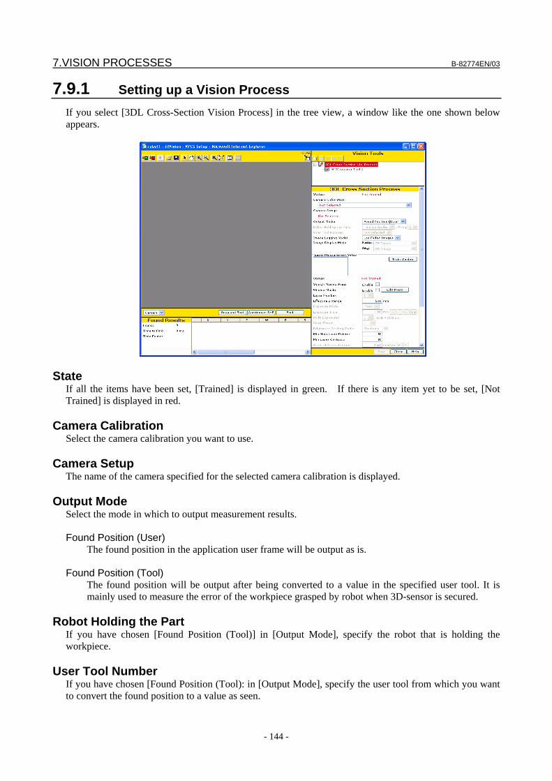
7.VISION PROCESSES B-82774EN/03
- 144 -
7.9.1 Setting up a Vision Process If you select [3DL Cross-Section Vision Process] in the tree view, a window like the one shown below appears.
State If all the items have been set, [Trained] is displayed in green. If there is any item yet to be set, [Not Trained] is displayed in red.
Camera Calibration Select the camera calibration you want to use.
Camera Setup The name of the camera specified for the selected camera calibration is displayed.
Output Mode Select the mode in which to output measurement results. Found Position (User)
The found position in the application user frame will be output as is. Found Position (Tool)
The found position will be output after being converted to a value in the specified user tool. It is mainly used to measure the error of the workpiece grasped by robot when 3D-sensor is secured.
Robot Holding the Part
If you have chosen [Found Position (Tool)] in [Output Mode], specify the robot that is holding the workpiece.
User Tool Number If you have chosen [Found Position (Tool): in [Output Mode], specify the user tool from which you want to convert the found position to a value as seen.
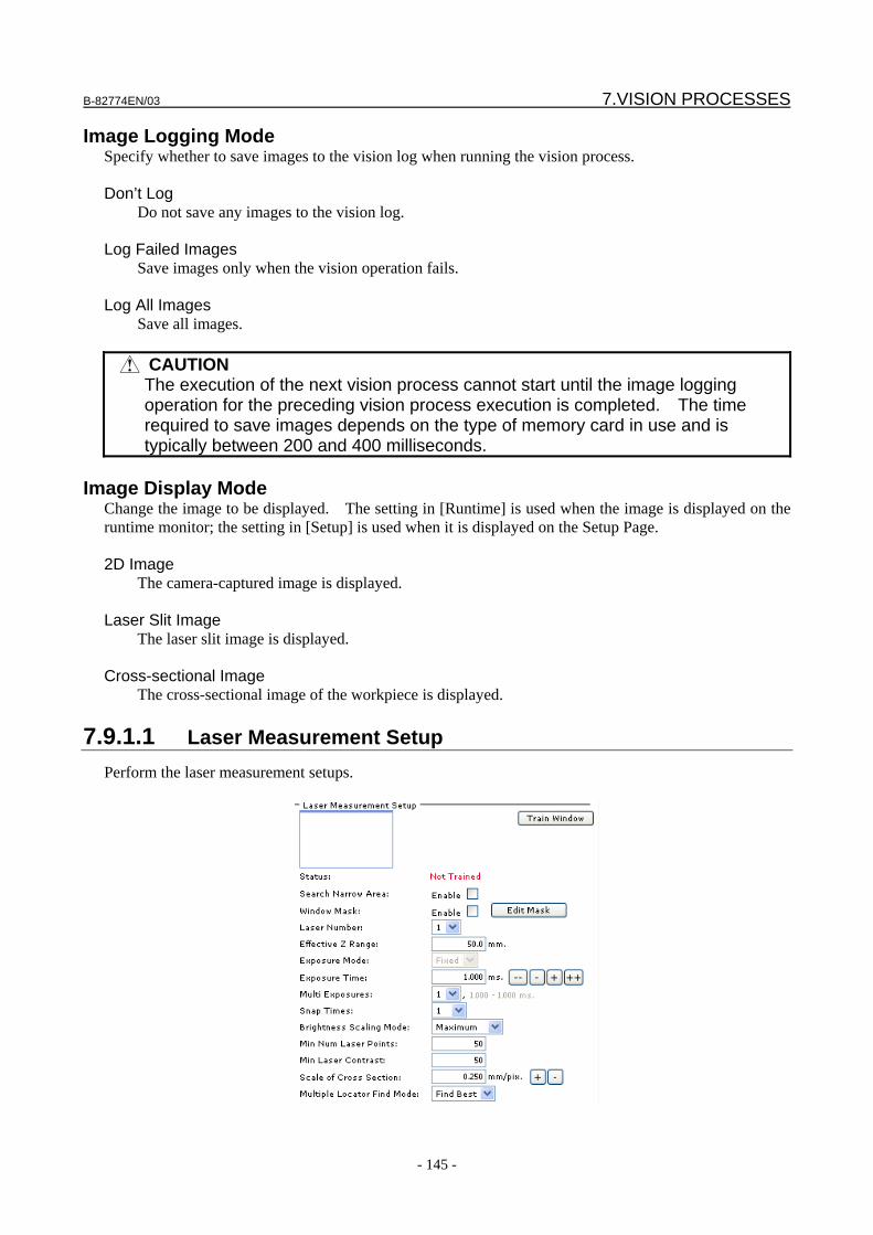
B-82774EN/03 7.VISION PROCESSES
- 145 -
Image Logging Mode Specify whether to save images to the vision log when running the vision process. Don’t Log
Do not save any images to the vision log. Log Failed Images
Save images only when the vision operation fails. Log All Images
Save all images.
CAUTION The execution of the next vision process cannot start until the image logging
operation for the preceding vision process execution is completed. The time required to save images depends on the type of memory card in use and is typically between 200 and 400 milliseconds.
Image Display Mode
Change the image to be displayed. The setting in [Runtime] is used when the image is displayed on the runtime monitor; the setting in [Setup] is used when it is displayed on the Setup Page. 2D Image
The camera-captured image is displayed. Laser Slit Image
The laser slit image is displayed. Cross-sectional Image
The cross-sectional image of the workpiece is displayed.
7.9.1.1 Laser Measurement Setup Perform the laser measurement setups.
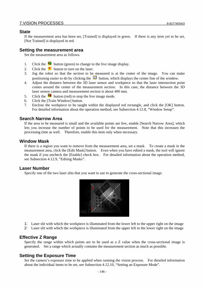
7.VISION PROCESSES B-82774EN/03
- 146 -
State If the measurement area has been set, [Trained] is displayed in green. If there is any item yet to be set, [Not Trained] is displayed in red.
Setting the measurement area Set the measurement area as follows. 1. Click the button (green) to change to the live image display. 2. Click the button to turn on the laser. 3. Jog the robot so that the section to be measured is at the center of the image. You can make
positioning easier to do by clicking the button, which displays the center line of the window. 4. Adjust the distance between the 3D laser sensor and workpiece so that the laser intersection point
comes around the center of the measurement section. In this case, the distance between the 3D laser sensor camera and measurement section is about 400 mm.
5. Click the button (red) to stop the live image mode. 6. Click the [Train Window] button. 7. Enclose the workpiece to be taught within the displayed red rectangle, and click the [OK] button.
For detailed information about the operation method, see Subsection 4.12.8, “Window Setup”.
Search Narrow Area If the area to be measured is small and the available points are few, enable [Search Narrow Area], which lets you increase the number of points to be used for the measurement. Note that this increases the processing time as well. Therefore, enable this item only when necessary.
Window Mask If there is a region you want to remove from the measurement area, set a mask. To create a mask in the measurement area, click the [Edit Mask] button. Even when you have edited a mask, the tool will ignore the mask if you uncheck the [Enable] check box. For detailed information about the operation method, see Subsection 4.12.9, “Editing Masks”.
Laser Number Specify one of the two laser slits that you want to use to generate the cross-sectional image.
1
2
1
2
1: Laser slit with which the workpiece is illuminated from the lower left to the upper right on the image 2: Laser slit with which the workpiece is illuminated from the upper left to the lower right on the image
Effective Z Range Specify the range within which points are to be used as a Z value when the cross-sectional image is generated. Set a range which actually contains the measurement section as much as possible.
Setting the Exposure Time Set the camera’s exposure time to be applied when running the vision process. For detailed information about the individual items to be set, see Subsection 4.12.10, “Setting an Exposure Mode”.
B-82774EN/03 7.VISION PROCESSES
- 147 -
Snap Times
Use this item when you want to snap multiple images during one exposure time to obtain an average image. This setting is valid only when a value of 1 is set in [Multi Exposure].
Brightness Scaling Mode This item is valid only when a value of 2 or greater is set in [Snap Times]. Select the pixel output mode when the maximum value obtained by the sum of the brightness values of pixels exceeds 255. Maximum
Each pixel in the area is adjusted with the same ratio so that the brightness of the brightest pixel is set to 255 and output them.
Summation
Pixels output as is unless the brightness of any pixel does not exceed 255 regardless of the brightness of the brightest pixel. This item is effective when the workpiece has a very bright part such as a mirror finished surface and an appropriate image cannot be obtained with the maximum brightness.
Min. Num. Laser Points
If the number of effective points found in the measurement area, excluding the mask area, is below this threshold, the measurement result is invalid. If the laser point found result varies because of a small measurement area or change in image brightness, lowering the minimum number of laser points might make location possible. Note that, because the inclination of the workpiece plane is calculated from the found points, measurement accuracy can degrade as the number of points decreases. The number of effective laser points to be found depends on the [Min. Laser Contrast] shown below.
Min. Laser Contrast This is the threshold for finding points of the laser applied to the measurement area, excluding the mask area. [Min. Num. Laser Points] and [Min. Laser Contrast] above should be confined to those cases where adjusting other settings never yields accurate found results. Forcing the tool to find laser points or changing the values inadvertently might result in inaccurate calculation of the detection position.
CAUTION Before changing location parameters [Min. Num. Laser Points] and [Min. Laser
Contrast], check that the laser measurement exposure time in the vision process has been adjusted so that an image is captured adequately.
Scale of Cross Section
Set the resolution (mm/pixel) of the generated cross-sectional image.
Multi-Locator Find Mode If you have created more than one locator tool, select how to execute those tools. Find Best
All the locator tools will be executed, and the best result will be chosen. This is effective when you want to identify the type or put location accuracy before processing time.
Find First
The locator tools will be executed sequentially from the top. The location process will stop as soon as the specified number of workpieces have been found. The subsequent locator tools will not be executed.
7.VISION PROCESSES B-82774EN/03
- 148 -
7.9.1.2 2D Measurement Setups
Perform the 2D measurement setups.
Setting the Exposure Time Set the camera’s exposure time to be applied when running the vision process. For detailed information about the individual items to be set, see Subsection 4.12.10, “Setting an Exposure Mode”. The exposure time specified here is used only setup mode only. In runtime the 3DL cross-section vision process, finds the workpiece by using the cross-section image generated from the laser image, so the 2D image is not snapped. Therefore the exposure time specified here is not used during runtime.
7.9.2 Running a Test Test to check whether the tool behaves as expected.
Snap and Find button The tool snaps an image from the camera and attempts to find a workpiece.
Continuous S+F button The tool repeats the Snap and Find operation.
Find button The tool only attempts to find a workpiece without snapping an image. Use this function when you want to confirm the effect of the same image with different location parameters.
B-82774EN/03 7.VISION PROCESSES
- 149 -
Num. Found The number of found workpieces is displayed.
Time to Find The time the location process took is displayed in milliseconds. If you have clicked the [Snap and Find] button, this includes both the time it took to snap the image and the time it took to process it. If you have clicked the [Find] button, this only represents the time it took to process the image and not the time it took to snap it.
Found Results table The following values are displayed. X, Y, Z
Coordinates of the model origin of the found workpiece using the cross-sectional image (units: mm).
W, P, R
These values are all 0 (units: degrees). Model ID
Model ID of the found workpiece using the cross-sectional image. Score
Score of the found workpiece using the cross-sectional image. Contrast
Contrast of the found workpiece using the cross-sectional image. Fit Error
Elasticity of the found workpiece using the cross-sectional image (units: pixels). Laser Points
Number of laser points used to generate the cross-sectional image.
7.VISION PROCESSES B-82774EN/03
- 150 -
7.10 SINGLE VIEW VISUAL TRACKING This is a vision process for a two-dimensional application that finds a workpiece being carried on a conveyor with a single camera and picks up the workpiece without stopping the conveyor.
7.10.1 Setting up a Vision Process If you select [Single View Visual Tracking] in the tree view, a screen like the one shown below appears.
Status If all the items have been set, [Trained] is displayed in green. If there is any item yet to be set, [Not Trained] is displayed in red.
Camera Calibration Select the camera calibration you want to use. The selectable camera calibrations are only those for visual tracking.
B-82774EN/03 7.VISION PROCESSES
- 151 -
Camera Setup The name of the camera specified for the selected camera calibration is displayed.
Line The name of the Line specified for the selected camera calibration is displayed. For detailed information about the Line, see Chapter 13, “VISUAL TRACKING”.
Exposure Time Specify the exposure time for the camera to capture an image. As the exposure time, specify the smallest possible value that does not cause the image of the moving conveyor to blur. As a guide, the value should be so small that the conveyor travels no more than 0.5 pixels during the exposure time.
Image Logging Mode Specify whether to save images to the vision log when running the vision process. While the options shown below are available, choose [Don’t Log] for visual tracking under normal conditions, because the image saving processing takes time. Don’t Log
Do not save any images to the vision log. Log Failed Images
Save images only when the vision operation fails. Log All Images
Save all images.
CAUTION The execution of the next vision process cannot start until the image logging
operation for the preceding vision process execution is completed. In case of this vision process, the time required to save images depends on the type of memory card in use and is typically between 200 and 400 milliseconds.
Runtime Image
Specify how to display an image on the runtime monitor. Display with 100%
The image will be displayed at a magnification of 100% on the runtime monitor. Display with 50%
The image will be displayed at a magnification of 50% on the runtime monitor. Don’t Display
No image will be displayed on the runtime monitor. Since displaying an image on the runtime monitor takes time, choose an option as appropriate for the system's tracking time requirement. If you choose [Don’t Display], no image will be displayed on the runtime monitor, allowing the vision process to run fastest. While [Display with 50%] takes more time than [Don’t Display], it is faster than [Display with 100%].
7.VISION PROCESSES B-82774EN/03
- 152 -
Duplicate Results Tolerance The position and angle of each found result is checked to see whether the result is the same as another result. If there are multiple found results within the specified pixels and angle, the results are assumed to the same workpiece and only the found result with the highest score is output.
Reference Data The reference data is used to calculate offset data from the found result. The reference data mainly consists of two types of data described below. Part Z Height
Height of the found part of the workpiece as seen from the tracking coordinate system. Reference Position
Position of the workpiece found when the robot position is taught. The offset data is the difference between the actual workpiece position found when running the vision process and the reference position.
A vision process might have more than one set of reference data. Under normal conditions, only one set of reference data is used. However, for example, if there are two types of workpieces being carried on the conveyor, each having a different height, the vision process uses two sets of reference data because it needs to set a different "Z-direction height" for each of the workpieces.
Reference Data Index to Use Choose one of the following to specify how to determine the reference data to use. This Index
The same reference data is used to calculate the offset data. Model ID
Different reference data is used depending on the model ID of the found workpiece. Choose this in such cases as when there are two types of workpiece having different heights.
ID
If [This Index] is selected in [Ref.Data Index To Use], enter the reference data ID to use.
Adding reference data You can add or delete reference data as follows. 1. Click the button. 2. In [Model ID], enter the model ID for which to use the reference data.
Part Z Height Enter the height of the found part of the workpiece as seen from the tracking frame.
CAUTION This is not the height from the surface of the conveyor. For example, if a thick
calibration grid is used to set up the tracking frame, then the value to be set is obtained by subtracting the thickness of the calibration grid from the height of the workpiece.
Reference Position Status
If the reference position is set, [Set] is displayed in green; otherwise, [Not Set] is displayed in red.

B-82774EN/03 7.VISION PROCESSES
- 153 -
Reference Position X,Y,R The coordinates of the set reference position are displayed.
7.10.2 Running a Test Run a test to check whether the tool behaves as expected.
Snap and Find button The tool snaps an image from the camera and attempts to find a workpiece.
Continuous S+F button The tool repeats the Snap and Find operation.
Find button The tool only attempts to find a workpiece without snapping an image. Use this function when you want to confirm the effect of the same image with different location parameters.
Found The number of found workpieces is displayed.
Time to Find The time the location process took is displayed in milliseconds. If you have clicked the [Snap and Find] button, this includes both the time it took to snap the image and the time it took to process it. If you have clicked the [Find] button, this only represents the time it took to process the image and not the time it took to snap it.
Found Result Table
The following values are displayed. X,Y
Coordinate values of the model origin of the found workpiece (units: mm). R
Rotation angle of the found workpiece around the Z axis (units: degrees).
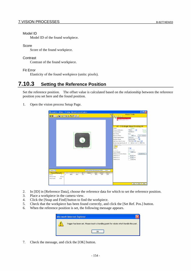
7.VISION PROCESSES B-82774EN/03
- 154 -
Model ID
Model ID of the found workpiece. Score
Score of the found workpiece. Contrast
Contrast of the found workpiece. Fit Error
Elasticity of the found workpiece (units: pixels).
7.10.3 Setting the Reference Position Set the reference position. The offset value is calculated based on the relationship between the reference position you set here and the found position. 1. Open the vision process Setup Page.
2. In [ID] in [Reference Data], choose the reference data for which to set the reference position. 3. Place a workpiece in the camera view. 4. Click the [Snap and Find] button to find the workpiece. 5. Check that the workpiece has been found correctly, and click the [Set Ref. Pos.] button. 6. When the reference position is set, the following message appears.
7. Check the message, and click the [OK] button.
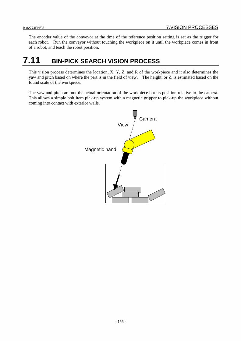
B-82774EN/03 7.VISION PROCESSES
- 155 -
The encoder value of the conveyor at the time of the reference position setting is set as the trigger for each robot. Run the conveyor without touching the workpiece on it until the workpiece comes in front of a robot, and teach the robot position.
7.11 BIN-PICK SEARCH VISION PROCESS This vision process determines the location, X, Y, Z, and R of the workpiece and it also determines the yaw and pitch based on where the part is in the field of view. The height, or Z, is estimated based on the found scale of the workpiece. The yaw and pitch are not the actual orientation of the workpiece but its position relative to the camera. This allows a simple bolt item pick-up system with a magnetic gripper to pick-up the workpiece without coming into contact with exterior walls.
Camera
View
Magnetic hand
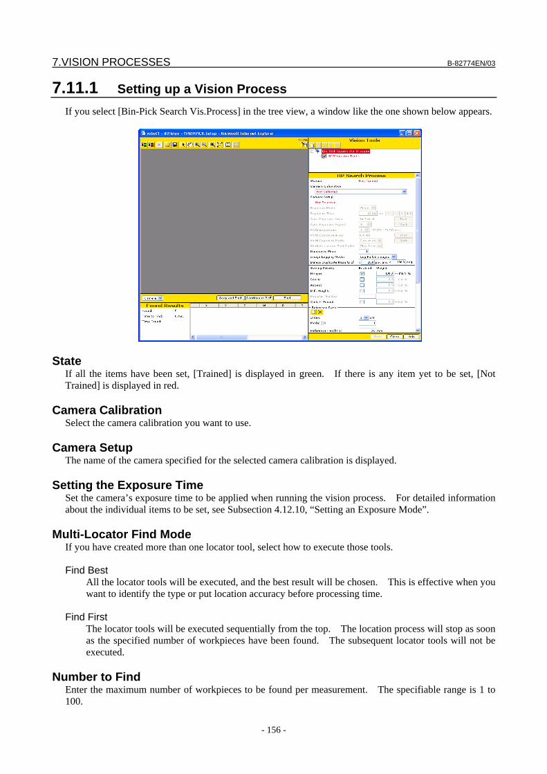
7.VISION PROCESSES B-82774EN/03
- 156 -
7.11.1 Setting up a Vision Process If you select [Bin-Pick Search Vis.Process] in the tree view, a window like the one shown below appears.
State If all the items have been set, [Trained] is displayed in green. If there is any item yet to be set, [Not Trained] is displayed in red.
Camera Calibration Select the camera calibration you want to use.
Camera Setup The name of the camera specified for the selected camera calibration is displayed.
Setting the Exposure Time Set the camera’s exposure time to be applied when running the vision process. For detailed information about the individual items to be set, see Subsection 4.12.10, “Setting an Exposure Mode”.
Multi-Locator Find Mode If you have created more than one locator tool, select how to execute those tools. Find Best
All the locator tools will be executed, and the best result will be chosen. This is effective when you want to identify the type or put location accuracy before processing time.
Find First
The locator tools will be executed sequentially from the top. The location process will stop as soon as the specified number of workpieces have been found. The subsequent locator tools will not be executed.
Number to Find
Enter the maximum number of workpieces to be found per measurement. The specifiable range is 1 to 100.
B-82774EN/03 7.VISION PROCESSES
- 157 -
Image Logging Mode Specify whether to save images to the vision log when running the vision process. Don’t Log
Do not save any images to the vision log. Log Failed Images
Save images only when the vision operation fails. Log All Images
Save all images.
CAUTION The execution of the next vision process cannot start until the image logging
operation for the preceding vision process execution is completed. The time required to save images depends on the type of memory card in use and is typically between 200 and 400 milliseconds per camera view.
Delete Duplicate Results If
The position and angle of each found result are checked to see whether the result is duplicated with another result. If there are multiple found results within the specified pixels and angle, the results are assumed to indicate the same workpiece and only the found result with the highest score is output.
Sorting Priority Specify the priority to determine the pick-up order to be applied when more than one workpiece has been found. The [Bin-Pick Search Vis.Process] calculates the priority using the results of the following five items and sorts the results unlike other vision processes. You can specify which items are used for priority calculation and how much these items reflect the calculation by checking [Enabled] for each required item and setting weight for them. Priorities calculated according to these settings are relative values for comparing workpieces with each other. The same priority is not always given to a found workpiece with the same size and score because calculation is performed so that the average priority of all workpieces found at a time is almost 50. Height
Priority is given to a workpiece with the largest Z value in the application user frame. Score
Priority is given to a workpiece with a high score in the found result. Aspect
Priority is given to a workpiece with a high ellipticity, that is, a small inclination. Diff.Height
Priority is given to a workpiece with a height closest to the height (Z value in the application user frame) of the workpiece last picked out.
Child N Found
As a pattern match model, the entire workpiece is taught to the parent pattern match tool. Then, as a child tool of the parent pattern match, part of the workpiece is taught. Priority is given to a workpiece with the maximum number of child tools. Use this item when you want to give priority to a workpiece with a small section hidden by another workpiece.
7.VISION PROCESSES B-82774EN/03
- 158 -
Reference Data The reference data is used to calculate offset data from the found results. The vision processes can have more than one reference data. Typically, the vision process only has one reference data. However, in such a case two types of workpieces are mixed, it is required to set the parameter which used to determine the Z-direction height of the workpiece, the reference data and so on for each types of workpieces, so two reference data are used.
Adding reference data You can add reference data as follows. 1. Click the button. 2. In [Model ID], enter the model ID for which to use the reference data.
Register Number Use this item when [Use Register Value] is chosen in [App. Z Mode]. Specify the number of the register that stores the workpiece height. To enable this field enable the Diff. Height field and give it a non zero weight.
Setting the Reference Height and Size Use this item when [Calculate From Found Scale] is chosen in [App. Z Mode]. Set the relationship between the actual Z-direction height of the workpiece and the apparent size of the workpiece captured by the camera. 1. Place one workpiece in the field of view. Determine the height of the workpiece above or below
the application user frame, this can be done using the robot with a pointer tool if desired. Enter this height data in [Reference Height 1].
2. Click the [Snap and Find] button to find the workpiece. Then, click the [Set Scale] button and set [Reference Scale 1].
3. Place a second workpiece in the field of view at a different height than the first. Determine the height of the workpiece above or below the application user frame, enter this height data in [Reference Height 2].
4. Click the [Snap and Find] button to find the workpiece. Then, click the [Set Scale] button and set [Reference Scale 2].
Reference Position Status
If the reference position is set, [Set] is displayed in green; otherwise, [Not Set] is displayed in red.
Reference X, Y, Z, W, P, R The coordinates of the set reference position are displayed.
Offset Limit Specify the condition used to check whether the calculated offset value is within the specified range. By default, [None selected] is set, in which case the offset limit check is not made. For information about the offset limit check conditions, see Section 9.2, "OFFSET LIMIT".
B-82774EN/03 7.VISION PROCESSES
- 159 -
7.11.2 Running a Test Test to check whether the tool behaves as expected.
Snap and Find button The tool snaps an image from the camera and attempts to find a workpiece.
Continuous S+F button The tool repeats the Snap and Find operation.
Find button The tool only attempts to find a workpiece without snapping an image. Use this function when you want to confirm the effect of the same image with different location parameters.
Num. Found The number of found workpieces is displayed.
Time to Find The time the location process took is displayed in milliseconds. If you have clicked the [Snap and Find] button, this includes both the time it took to snap the image and the time it took to process it. If you have clicked the [Find] button, this only represents the time it took to process the image and not the time it took to snap it.
Found Results table The following values are displayed. X, Y, Z
Coordinates of the model origin of the found workpiece (units: mm). W, P
Inclination of the gaze line connecting the camera and found workpiece (units: degrees). R
Rotation angle of the found workpiece around the Z-axis (units: degrees).
7.VISION PROCESSES B-82774EN/03
- 160 -
Model ID
Model ID of the found workpiece. Score
Score of the found workpiece. Size
Size of the found workpiece. Contrast
Contrast of the found workpiece. Fit Error
Elasticity of the found workpiece (units: pixels). Priority
Pick-up priority given to the found workpiece.
NOTE If you run a find test without setting the reference Z-direction height or size,
******** is displayed for X, Y, Z, W, P, and R because these values cannot be calculated.
7.11.3 Setting the Reference Position Set the reference position. The offset value is calculated based on the relationship between the reference position you set here and the found position.
1. Open the vision process Setup Page. 2. Place a workpiece in the camera view for which you want to set the reference position. 3. Click the [Snap and Find] button to find the workpiece. 4. Click the [Set Ref. Pos.] button. 5. Check that [Reference Position Status] is set to [Set] and that a value is displayed for each reference
position element.
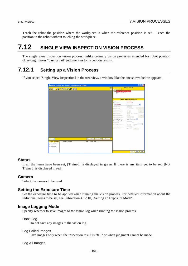
B-82774EN/03 7.VISION PROCESSES
- 161 -
Teach the robot the position where the workpiece is when the reference position is set. Teach the position to the robot without touching the workpiece.
7.12 SINGLE VIEW INSPECTION VISION PROCESS The single view inspection vision process, unlike ordinary vision processes intended for robot position offsetting, makes "pass or fail" judgment as to inspection results.
7.12.1 Setting up a Vision Process If you select [Single-View Inspection] in the tree view, a window like the one shown below appears.
Status If all the items have been set, [Trained] is displayed in green. If there is any item yet to be set, [Not Trained] is displayed in red.
Camera Select the camera to be used.
Setting the Exposure Time Set the exposure time to be applied when running the vision process. For detailed information about the individual items to be set, see Subsection 4.12.10, "Setting an Exposure Mode".
Image Logging Mode Specify whether to save images to the vision log when running the vision process. Don't Log Do not save any images to the vision log. Log Failed Images Save images only when the inspection result is "fail" or when judgment cannot be made. Log All Images
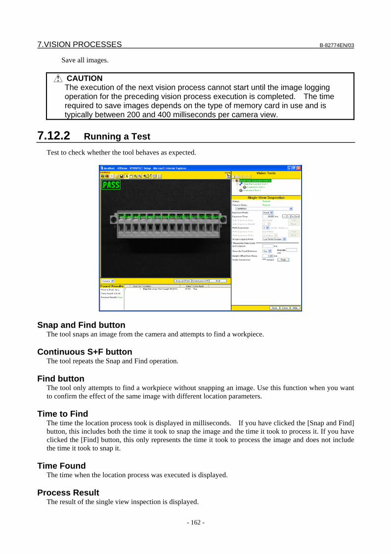
7.VISION PROCESSES B-82774EN/03
- 162 -
Save all images.
CAUTION The execution of the next vision process cannot start until the image logging
operation for the preceding vision process execution is completed. The time required to save images depends on the type of memory card in use and is typically between 200 and 400 milliseconds per camera view.
7.12.2 Running a Test Test to check whether the tool behaves as expected.
Snap and Find button The tool snaps an image from the camera and attempts to find a workpiece.
Continuous S+F button The tool repeats the Snap and Find operation.
Find button The tool only attempts to find a workpiece without snapping an image. Use this function when you want to confirm the effect of the same image with different location parameters.
Time to Find The time the location process took is displayed in milliseconds. If you have clicked the [Snap and Find] button, this includes both the time it took to snap the image and the time it took to process it. If you have clicked the [Find] button, this only represents the time it took to process the image and does not include the time it took to snap it.
Time Found The time when the location process was executed is displayed.
Process Result The result of the single view inspection is displayed.
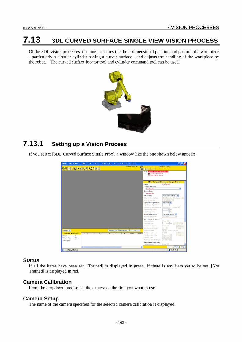
B-82774EN/03 7.VISION PROCESSES
- 163 -
7.13 3DL CURVED SURFACE SINGLE VIEW VISION PROCESS Of the 3DL vision processes, this one measures the three-dimensional position and posture of a workpiece - particularly a circular cylinder having a curved surface - and adjusts the handling of the workpiece by the robot. The curved surface locator tool and cylinder command tool can be used.
7.13.1 Setting up a Vision Process If you select [3DL Curved Surface Single Proc], a window like the one shown below appears.
Status If all the items have been set, [Trained] is displayed in green. If there is any item yet to be set, [Not Trained] is displayed in red.
Camera Calibration From the dropdown box, select the camera calibration you want to use.
Camera Setup The name of the camera specified for the selected camera calibration is displayed.
7.VISION PROCESSES B-82774EN/03
- 164 -
Offset Mode From the combo box, select one of the following robot position offset modes: Fixed Frame Offset The fixed frame offset data will be calculated. Tool Offset The tool offset data will be calculated. Found Position (User) The found position will be output as is, instead of the offset data. This option is provided for any
required specified offset mode. Do not select it under normal conditions. Found Position (Tool) The found position will be output, instead of the offset data, after being converted to a value as seen
from the tool frame. This option is provided for any required specified offset mode. Do not select it under normal conditions
Robot Holding Part
If you have chosen [Tool Offset] or [Found Position (Tool)] for [Offset Mode], specify the robot holding the workpiece.
User Tool Number If you have chosen [Tool Offset] or [Found Position (Tool)] for [Offset Mode], specify the user tool in which you will perform position offset.
Setting the Light Use this function to have an external light turned on or off as appropriate for the vision process executed with the 3D laser sensor. By using this function, you can have the light turned on, for example, when finding two-dimensional features during one three-dimensional measurement, or have it turned off when finding the laser lines. Set the function as follows. 1. In [Light Output Signal Type], specify the type of signal - DO or RO - that turns on or off the light. 2. In [Light Output Signal Number], enter the number of the output point to which the ON/OFF signal
is connected. For example, when connecting the signal to RO[1], enter 1. 3. In [Light Output Signal Polarity], set the relationship between the signal output and turning on or off
the light. To turn on the light when the signal is ON, set [Signal=On->Light On]. To turn it off when the signal is ON, set [Signal=Off->Light On].
4. In [Light on Snap Delay], set the wait time from the output of the light ON signal until an image is snapped. Under normal conditions, set 0.
Lean Angle Limit
Any workpiece found with an angle greater than the lean angle limit from the reference position is treated as not being found.
Image Logging Mode From the combo box, select one of the following image logging modes: Don't Log Do not save any images to the vision log. This mode enables the fastest logging and consumes the
least amount of memory card space. Log Failed Images
B-82774EN/03 7.VISION PROCESSES
- 165 -
Save images only when the vision operation fails. This mode is effective when you want to analyze failed images later for corrective action.
Log All Images Save all images. This mode is effective when you want to obtain a large amount of image data for
adjusting the location parameters.
CAUTION The execution of the next vision process cannot start until the image logging
operation for the preceding vision process execution is completed. The time required to save images depends on the type of memory card in use and is typically between 600 and 1200 milliseconds per camera view.
Image Display Mode
Select the items to be displayed in the vision image display area. 2D Image The 2D image and location result are displayed. Laser Slit Image 1 The slit image of laser 1 is displayed. Laser Slit Image 2 The slit image of laser 2 is displayed.
7.13.1.1 2D Measurement Setups Perform the 2D measurement setups.
Setting the Exposure Time Set the camera’s exposure time to be applied when running the vision process. For detailed information about the individual items to be set, see Subsection 4.12.10, "Setting an Exposure Mode".
Light For Snap Set whether to turn on or off the light when snapping an image for 2D measurement.
Multi-Locator Find mode If you have created more than one locator tool, select how to execute those tools. Find Best All the locator tools will be executed, and the best result will be chosen. This is effective when you
want to identify the type or put location accuracy before processing time.
7.VISION PROCESSES B-82774EN/03
- 166 -
Find First The locator tools will be executed sequentially from the top. The location process will stop as soon
as the specified number of workpieces have been found. The subsequent locator tools will not be executed.
7.13.1.2 Laser Measurement Setup
Perform the laser measurement setups.
Setting the Exposure Time Set the camera’s exposure time to be applied when running the vision process. For detailed information about the individual items to be set, see Subsection 4.12.10, "Setting an Exposure Mode".
Snap Times Use this item when you want to snap multiple images during one exposure time and to obtain an average image. This setting is valid only when 1 is set in [Multi Exposures].
Brightness Scaling Mode Specify a method for coordinating the brightness when laser images obtained by multi-exposure are combined. Maximum After all laser images are summed up, the brightness of the whole image is scaled so that the
brightness in the photometric area is lower than 256. If halation occurs at even one point in the photometric area, the image becomes relatively dark as a whole.
Summation After all laser images are summed up, the brightness of the pixel, brightness of which is higher than
256, is clipped. The brightness of whole image is kept and the brightness of pixels in which halation occurs is only suppressed to 255.
Light For Snap
Set whether to turn on or off the light when snapping an image for laser measurement.
TIP If more than one laser measurement tool, such as cylinder command tool or 3DL
displ. command tool, has been created, the tools will be executed sequentially from the top, and the measurement process will stop as soon as a measurement succeeds, leaving the subsequent tools unexecuted.
B-82774EN/03 7.VISION PROCESSES
- 167 -
7.13.1.3 Setting Reference Data Set the reference position.
Setting the Reference Position If the reference position is set, [Set] is displayed in green. Otherwise, [Not Set] is displayed in red.
Reference X, Y, Z, W, P, R The coordinates of the set reference position are displayed.
Offset Limit Specify the condition used to check whether the calculated offset value is within the specified range. By default, [None selected] is set, in which case the offset limit check is not made. For information about the offset limit check conditions, see Section 9.2, "OFFSET LIMIT".
7.13.2 Running a Test Test to check whether the tool behaves as expected.
Snap and Find button The tool snaps an image from the camera and attempts to find a workpiece.
Continuous S+F button The tool repeats the Snap and Find operation.
7.VISION PROCESSES B-82774EN/03
- 168 -
Find button
The tool only attempts to find a workpiece without snapping an image. Use this function when you want to confirm the effect of the same image with different location parameters.
Num. Found The number of found workpieces is displayed.
Time to Find The time the location process took is displayed in milliseconds. If you have clicked the [Snap and Find] button, this includes both the time it took to snap the image and the time it took to process it. If you have clicked the [Find] button, this only represents the time it took to process the image and does not include the time it took to snap it.
Found Result Table
The following values are displayed. X, Y, Z Coordinates of the model origin of the found workpiece (unit: mm). W, P, R Rotation angle of the found workpiece around the X, Y, and Z axis (unit: degrees). Laser ID Laser measurement ID of the found workpiece. Model ID Model ID of the found workpiece. Score Score of the found workpiece. Contrast Contrast of the found workpiece. Fit Err. Elasticity of the found workpiece (unit: pixels). Lean Angle Inclination angle of the found workpiece in the normal direction at the reference position (unit:
degrees).
7.13.3 Setting the Reference Position Set the reference position. The offset value is calculated based on the relationship between the reference position you set here and the found position. 1. Open the vision process Setup Page. 2. Place a workpiece in the camera view for which you want to set the reference position. 3. Click the [Snap and Find] button to find the workpiece. 4. Click the [Set Ref. Pos.] button. 5. Check that [Reference Position Status] is set to [Set] and that a value is displayed for each reference
position element.
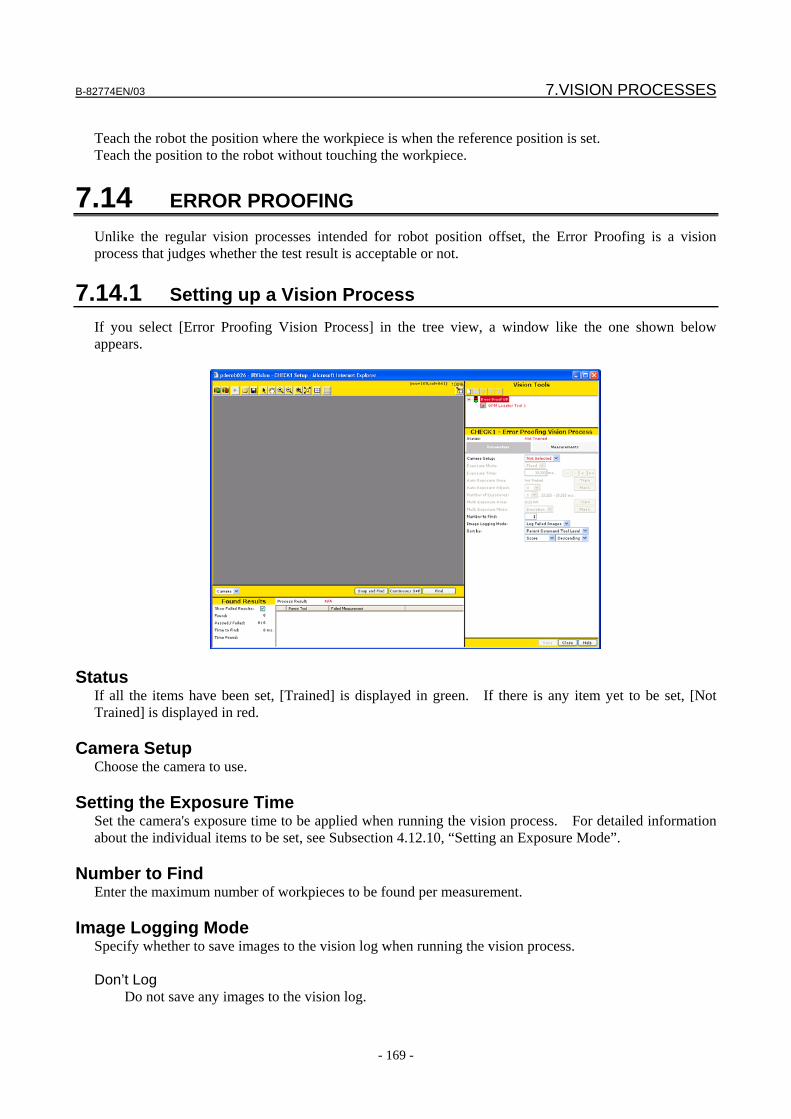
B-82774EN/03 7.VISION PROCESSES
- 169 -
Teach the robot the position where the workpiece is when the reference position is set. Teach the position to the robot without touching the workpiece.
7.14 ERROR PROOFING Unlike the regular vision processes intended for robot position offset, the Error Proofing is a vision process that judges whether the test result is acceptable or not.
7.14.1 Setting up a Vision Process If you select [Error Proofing Vision Process] in the tree view, a window like the one shown below appears.
Status If all the items have been set, [Trained] is displayed in green. If there is any item yet to be set, [Not Trained] is displayed in red.
Camera Setup Choose the camera to use.
Setting the Exposure Time Set the camera's exposure time to be applied when running the vision process. For detailed information about the individual items to be set, see Subsection 4.12.10, “Setting an Exposure Mode”.
Number to Find Enter the maximum number of workpieces to be found per measurement.
Image Logging Mode Specify whether to save images to the vision log when running the vision process. Don’t Log
Do not save any images to the vision log.
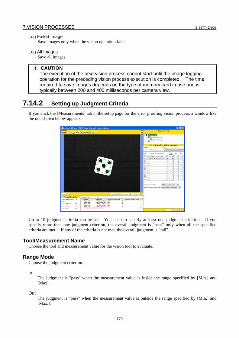
7.VISION PROCESSES B-82774EN/03
- 170 -
Log Failed Image Save images only when the vision operation fails.
Log All Images
Save all images.
CAUTION The execution of the next vision process cannot start until the image logging
operation for the preceding vision process execution is completed. The time required to save images depends on the type of memory card in use and is typically between 200 and 400 milliseconds per camera view.
7.14.2 Setting up Judgment Criteria If you click the [Measurements] tab in the setup page for the error proofing vision process, a window like the one shown below appears.
Up to 10 judgment criteria can be set. You need to specify at least one judgment criterion. If you specify more than one judgment criterion, the overall judgment is "pass" only when all the specified criteria are met. If any of the criteria is not met, the overall judgment is "fail".
Tool/Measurement Name Choose the tool and measurement value for the vision tool to evaluate.
Range Mode Choose the judgment criterion. In
The judgment is "pass" when the measurement value is inside the range specified by [Min.] and [Max].
Out
The judgment is "pass" when the measurement value is outside the range specified by [Min.] and [Max.].
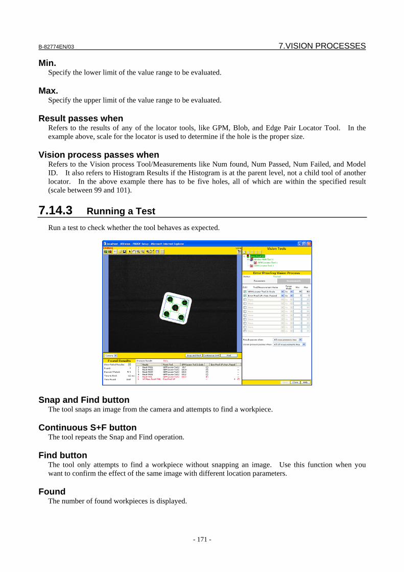
B-82774EN/03 7.VISION PROCESSES
- 171 -
Min. Specify the lower limit of the value range to be evaluated.
Max. Specify the upper limit of the value range to be evaluated.
Result passes when Refers to the results of any of the locator tools, like GPM, Blob, and Edge Pair Locator Tool. In the example above, scale for the locator is used to determine if the hole is the proper size.
Vision process passes when
Refers to the Vision process Tool/Measurements like Num found, Num Passed, Num Failed, and Model ID. It also refers to Histogram Results if the Histogram is at the parent level, not a child tool of another locator. In the above example there has to be five holes, all of which are within the specified result (scale between 99 and 101).
7.14.3 Running a Test Run a test to check whether the tool behaves as expected.
Snap and Find button The tool snaps an image from the camera and attempts to find a workpiece.
Continuous S+F button The tool repeats the Snap and Find operation.
Find button The tool only attempts to find a workpiece without snapping an image. Use this function when you want to confirm the effect of the same image with different location parameters.
Found The number of found workpieces is displayed.

7.VISION PROCESSES B-82774EN/03
- 172 -
Passed/Failed The number of passed workpieces and the number of failed workpieces are displayed. The passed and failed criteria are determined by the setup of the results in the tool/measurement name.
Time to Find The time the location process took is displayed in milliseconds. If you have clicked the [Snap and Find] button, this includes both the time it took to snap the image and the time it took to process it. If you have clicked the [Find] button, this only represents the time it took to process the image and not the time it took to snap it.
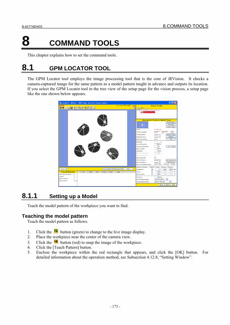
B-82774EN/03 8.COMMAND TOOLS
- 173 -
8 COMMAND TOOLS This chapter explains how to set the command tools.
8.1 GPM LOCATOR TOOL The GPM Locator tool employs the image processing tool that is the core of iRVision. It checks a camera-captured image for the same pattern as a model pattern taught in advance and outputs its location. If you select the GPM Locator tool in the tree view of the setup page for the vision process, a setup page like the one shown below appears.
8.1.1 Setting up a Model Teach the model pattern of the workpiece you want to find.
Teaching the model pattern Teach the model pattern as follows. 1. Click the button (green) to change to the live image display. 2. Place the workpiece near the center of the camera view. 3. Click the button (red) to snap the image of the workpiece. 4. Click the [Teach Pattern] button. 5. Enclose the workpiece within the red rectangle that appears, and click the [OK] button. For
detailed information about the operation method, see Subsection 4.12.8, “Setting Window”.
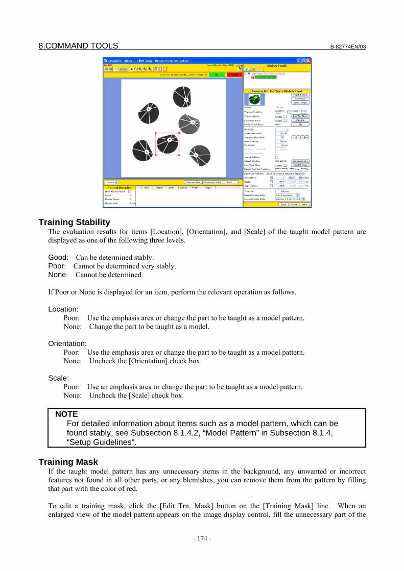
8.COMMAND TOOLS B-82774EN/03
- 174 -
Training Stability The evaluation results for items [Location], [Orientation], and [Scale] of the taught model pattern are displayed as one of the following three levels. Good: Can be determined stably. Poor: Cannot be determined very stably. None: Cannot be determined. If Poor or None is displayed for an item, perform the relevant operation as follows. Location:
Poor: Use the emphasis area or change the part to be taught as a model pattern. None: Change the part to be taught as a model.
Orientation:
Poor: Use the emphasis area or change the part to be taught as a model pattern. None: Uncheck the [Orientation] check box.
Scale:
Poor: Use an emphasis area or change the part to be taught as a model pattern. None: Uncheck the [Scale] check box.
NOTE For detailed information about items such as a model pattern, which can be
found stably, see Subsection 8.1.4.2, “Model Pattern” in Subsection 8.1.4, “Setup Guidelines".
Training Mask
If the taught model pattern has any unnecessary items in the background, any unwanted or incorrect features not found in all other parts, or any blemishes, you can remove them from the pattern by filling that part with the color of red. To edit a training mask, click the [Edit Trn. Mask] button on the [Training Mask] line. When an enlarged view of the model pattern appears on the image display control, fill the unnecessary part of the
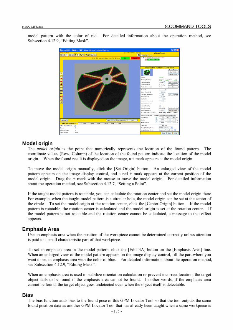
B-82774EN/03 8.COMMAND TOOLS
- 175 -
model pattern with the color of red. For detailed information about the operation method, see Subsection 4.12.9, “Editing Mask”.
Model origin The model origin is the point that numerically represents the location of the found pattern. The coordinate values (Row, Column) of the location of the found pattern indicate the location of the model origin. When the found result is displayed on the image, a + mark appears at the model origin. To move the model origin manually, click the [Set Origin] button. An enlarged view of the model pattern appears on the image display control, and a red + mark appears at the current position of the model origin. Drag the + mark with the mouse to move the model origin. For detailed information about the operation method, see Subsection 4.12.7, “Setting a Point”. If the taught model pattern is rotatable, you can calculate the rotation center and set the model origin there. For example, when the taught model pattern is a circular hole, the model origin can be set at the center of the circle. To set the model origin at the rotation center, click the [Center Origin] button. If the model pattern is rotatable, the rotation center is calculated and the model origin is set at the rotation center. If the model pattern is not rotatable and the rotation center cannot be calculated, a message to that effect appears.
Emphasis Area Use an emphasis area when the position of the workpiece cannot be determined correctly unless attention is paid to a small characteristic part of that workpiece. To set an emphasis area in the model pattern, click the [Edit EA] button on the [Emphasis Area] line. When an enlarged view of the model pattern appears on the image display control, fill the part where you want to set an emphasis area with the color of blue. For detailed information about the operation method, see Subsection 4.12.9, “Editing Mask”. When an emphasis area is used to stabilize orientation calculation or prevent incorrect location, the target object fails to be found if the emphasis area cannot be found. In other words, if the emphasis area cannot be found, the target object goes undetected even when the object itself is detectable.
Bias The bias function adds bias to the found pose of this GPM Locator Tool so that the tool outputs the same found position data as another GPM Locator Tool that has already been taught when a same workpiece is
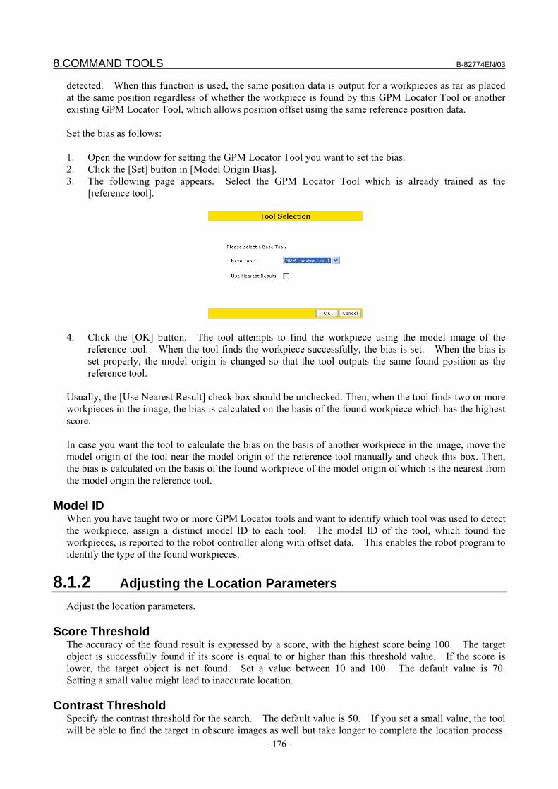
8.COMMAND TOOLS B-82774EN/03
- 176 -
detected. When this function is used, the same position data is output for a workpieces as far as placed at the same position regardless of whether the workpiece is found by this GPM Locator Tool or another existing GPM Locator Tool, which allows position offset using the same reference position data. Set the bias as follows: 1. Open the window for setting the GPM Locator Tool you want to set the bias. 2. Click the [Set] button in [Model Origin Bias]. 3. The following page appears. Select the GPM Locator Tool which is already trained as the
[reference tool].
4. Click the [OK] button. The tool attempts to find the workpiece using the model image of the
reference tool. When the tool finds the workpiece successfully, the bias is set. When the bias is set properly, the model origin is changed so that the tool outputs the same found position as the reference tool.
Usually, the [Use Nearest Result] check box should be unchecked. Then, when the tool finds two or more workpieces in the image, the bias is calculated on the basis of the found workpiece which has the highest score. In case you want the tool to calculate the bias on the basis of another workpiece in the image, move the model origin of the tool near the model origin of the reference tool manually and check this box. Then, the bias is calculated on the basis of the found workpiece of the model origin of which is the nearest from the model origin the reference tool.
Model ID When you have taught two or more GPM Locator tools and want to identify which tool was used to detect the workpiece, assign a distinct model ID to each tool. The model ID of the tool, which found the workpieces, is reported to the robot controller along with offset data. This enables the robot program to identify the type of the found workpieces.
8.1.2 Adjusting the Location Parameters Adjust the location parameters.
Score Threshold The accuracy of the found result is expressed by a score, with the highest score being 100. The target object is successfully found if its score is equal to or higher than this threshold value. If the score is lower, the target object is not found. Set a value between 10 and 100. The default value is 70. Setting a small value might lead to inaccurate location.
Contrast Threshold Specify the contrast threshold for the search. The default value is 50. If you set a small value, the tool will be able to find the target in obscure images as well but take longer to complete the location process.
B-82774EN/03 8.COMMAND TOOLS
- 177 -
The minimum value is 10. If the tool is prone to inadequately find blemishes and other unwanted edges with low contrast, try setting a larger value. Those image features whose contrast is lower than the threshold are ignored. Selecting the [Image+Edges] in [Image Display Mode] lets you check the image features extracted based on the current threshold.
Area Overlap If the ratio of overlap of the found objects is higher than the ratio specified here, then the found result for the workpiece with the lower score is deleted, leaving only the one with the higher score. The ratio of overlap is determined by the area where the models' external rectangular frames overlap. If you specify 100% as the limit value, the found results will not be deleted even if the workpieces overlap.
Elasticity Specify a pixel value to indicate how much the pattern in the image is allowed to be deviated (distorted) in geometry from the taught model. Setting a large value enables the tool to find the target in images that are greatly deviated in geometry. However, the larger the value is, the more likely inaccurate location becomes.
EA Score Threshold Besides the score threshold for the entire model, specify the score threshold for the emphasis area alone indicating how high the score must be for the object to be found. The default value is 70 points.
Allow Floating EA This can be specified to allow the tool to find an object even if the position of the emphasis area is deviated by two to three pixels relative to the position of the entire model pattern.
Search Window Specify the range of the area of the image to be searched. The narrower the range is, the faster the location process ends. The default value is the entire image. To change the search window, click the [Set Search Win.] button. When a rectangle appears on the image, adjust its geometry, as when teaching a model. For detailed information about the operation method, see Subsection 4.12.8, “Setting a Window”.
Run-Time Mask Specify an area of the search window that you do not want processed, as an arbitrary geometry. Use this function when you want to specify a search window of an arbitrary geometry, such as a circle- or donut-shaped window. The filled area will be masked in the rectangle specified as the search window and will not be subject to the image processing. To change the run-time mask, click the [Edit RT Mask] button. For detailed information about the operation method, see Subsection 4.12.9, “Editing a Mask”.
DOF - Orientation Specify the range of orientation subject to be searched. The tool searches for a model rotated in the range specified by [Minimum] and [Maximum], with the orientation of the taught model being 0 degrees. The specifiable value range is from −360 to +360 degrees for both [Minimum] and [Maximum]. The narrower the orientation range is, the faster the search process ends. If a range wider than 360 degrees is specified, the range is automatically corrected to 360 degrees when the vision process runs. If you uncheck this box, the orientation is ignored and the tool searches only for a model having the orientation specified in [Nominal]. By default, the orientation search is enabled and the range is from −180 to +180 degrees.

8.COMMAND TOOLS B-82774EN/03
- 178 -
DOF - Scale Specify the range of scale to be searched. With the size of the taught model being 100%, the tool searches for a model expanded or reduced by the ratio specified in [Minimum] and [Maximum]. The specifiable value range is from 25% to 400% for both [Minimum] and [Maximum]. The narrower the size range is, the faster the search process ends. If you uncheck this box, the scale is ignored and the tool searches only for a model having the scale specified in [Nominal]. By default, the scale search is disabled.
DOF - Aspect Specify the range of aspect ratios to be searched. With the ratio of the taught model being 100%, the tool searches for a model flattened by the ratio specified in [Minimum] and [Maximum]. The specifiable value range is from 50% to 100% for both [Minimum] and [Maximum]. The narrower the aspect ratio range is, the faster the search process ends. If you uncheck this box, the aspect ratio is ignored and the tool searches only for a model having the aspect ratio specified in [Nominal]. By default, the aspect ratio search is disabled.
Time-out If the location process takes longer than the time specified here, the tool ends the process without finding all of the workpieces.
Result Plotting Mode Select how the found results are to be displayed on the image after the process is run. Plot Everything
The origin, features, and rectangle of the model will be displayed. Plot Edges
Only the origin and features of the model will be displayed. Plot Bounding Box
Only the origin and rectangle of the model will be displayed. Plot Only Origin
Only the origin of the model will be displayed. Plot Nothing
Nothing will be displayed.
Image Display Mode Select the image display mode for the Setup Page. Image
Only the camera image will be displayed. Image+Results
The camera image and found results will be displayed.
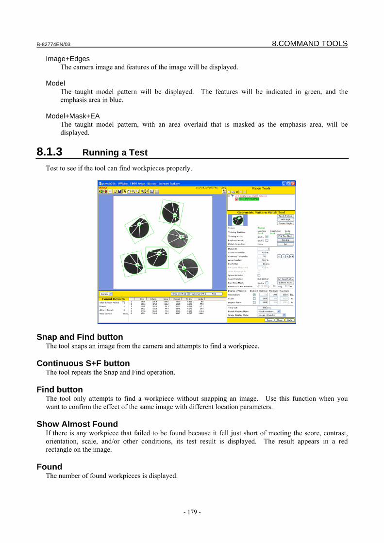
B-82774EN/03 8.COMMAND TOOLS
- 179 -
Image+Edges The camera image and features of the image will be displayed.
Model
The taught model pattern will be displayed. The features will be indicated in green, and the emphasis area in blue.
Model+Mask+EA
The taught model pattern, with an area overlaid that is masked as the emphasis area, will be displayed.
8.1.3 Running a Test Test to see if the tool can find workpieces properly.
Snap and Find button The tool snaps an image from the camera and attempts to find a workpiece.
Continuous S+F button The tool repeats the Snap and Find operation.
Find button The tool only attempts to find a workpiece without snapping an image. Use this function when you want to confirm the effect of the same image with different location parameters.
Show Almost Found If there is any workpiece that failed to be found because it fell just short of meeting the score, contrast, orientation, scale, and/or other conditions, its test result is displayed. The result appears in a red rectangle on the image.
Found The number of found workpieces is displayed.

8.COMMAND TOOLS B-82774EN/03
- 180 -
Almost Found The number of workpieces that failed to be found because they were slightly outside the specified range is displayed. "0" is displayed if the [Show Almost Found] check box is not checked.
Time to Find The time the location process took is displayed in milliseconds. This is the image processing time and does not include the time it took to snap the image.
Found Result Table The following values are displayed. Row, Column
Coordinate values of the model origin of the found pattern (units: pixels). Angle
Orientation of the found pattern (units: degrees). This is displayed only when the box for the orientation search is checked.
Scale
Scale of the found pattern (units: %). This is displayed only when the box for the scale search is checked.
Aspect Ratio
Aspect ratio of the found pattern (units: %). This is displayed only when the box for the aspect ratio search is checked.
Score
Score of the found pattern. Contrast
Contrast of the found pattern. Fit Error
Deviation of the found pattern from the model pattern (units: pixels). Emphasis Area
Score for the emphasis area only. This is displayed only when the box for the emphasis area is checked.
8.1.4 Setup Guidelines Read these guidelines for a deeper understanding of how the GPM Locator tool works.
8.1.4.1 Overview and functions This section provides an overview of the GPM Locator tool, describing what you can do and how you see objects with this tool.
What you can do with the GPM locator tool The GPM Locator Tool offers image processing capabilities to process images captured by the camera, find the same pattern in an image as the pattern taught in advance, and output the position and orientation of the found pattern. The pattern taught in advance is called a model pattern, or simply a model.
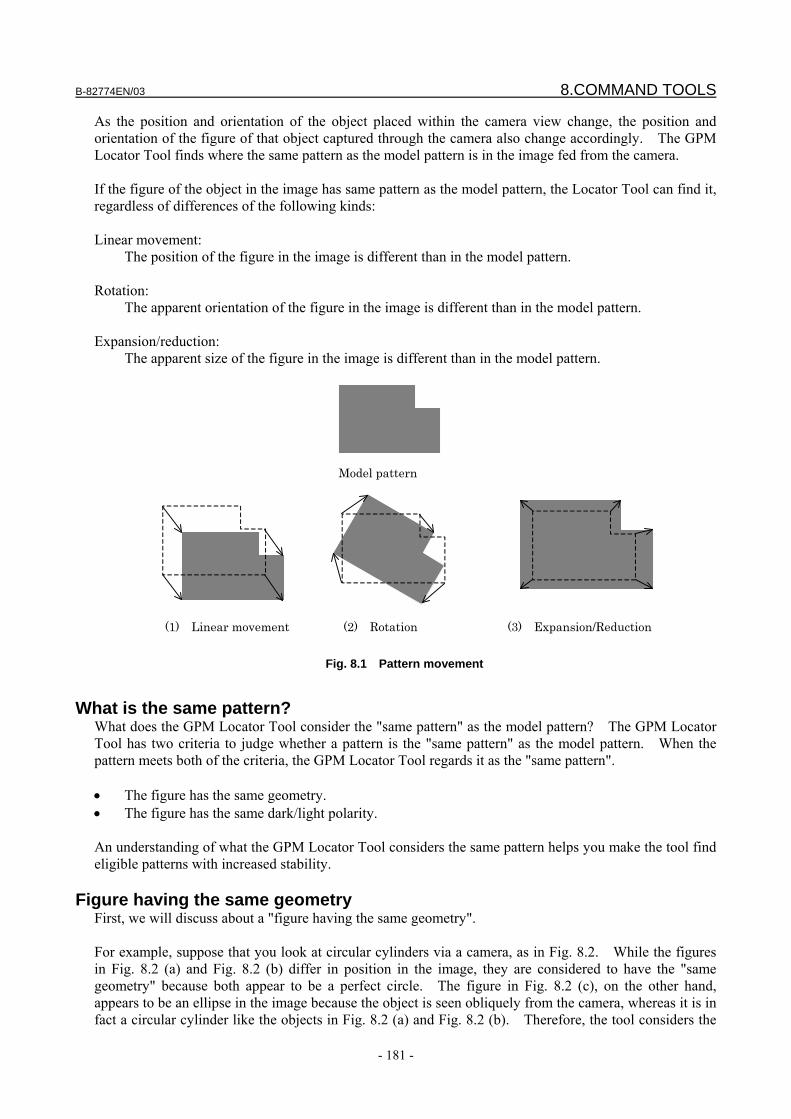
B-82774EN/03 8.COMMAND TOOLS
- 181 -
As the position and orientation of the object placed within the camera view change, the position and orientation of the figure of that object captured through the camera also change accordingly. The GPM Locator Tool finds where the same pattern as the model pattern is in the image fed from the camera. If the figure of the object in the image has same pattern as the model pattern, the Locator Tool can find it, regardless of differences of the following kinds: Linear movement:
The position of the figure in the image is different than in the model pattern. Rotation:
The apparent orientation of the figure in the image is different than in the model pattern. Expansion/reduction:
The apparent size of the figure in the image is different than in the model pattern.
Model pattern
(1) Linear movement (2) Rotation (3) Expansion/Reduction
Fig. 8.1 Pattern movement
What is the same pattern?
What does the GPM Locator Tool consider the "same pattern" as the model pattern? The GPM Locator Tool has two criteria to judge whether a pattern is the "same pattern" as the model pattern. When the pattern meets both of the criteria, the GPM Locator Tool regards it as the "same pattern". • The figure has the same geometry. • The figure has the same dark/light polarity. An understanding of what the GPM Locator Tool considers the same pattern helps you make the tool find eligible patterns with increased stability.
Figure having the same geometry First, we will discuss about a "figure having the same geometry". For example, suppose that you look at circular cylinders via a camera, as in Fig. 8.2. While the figures in Fig. 8.2 (a) and Fig. 8.2 (b) differ in position in the image, they are considered to have the "same geometry" because both appear to be a perfect circle. The figure in Fig. 8.2 (c), on the other hand, appears to be an ellipse in the image because the object is seen obliquely from the camera, whereas it is in fact a circular cylinder like the objects in Fig. 8.2 (a) and Fig. 8.2 (b). Therefore, the tool considers the
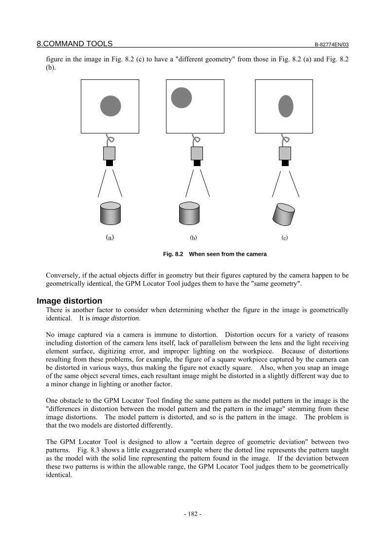
8.COMMAND TOOLS B-82774EN/03
- 182 -
figure in the image in Fig. 8.2 (c) to have a "different geometry" from those in Fig. 8.2 (a) and Fig. 8.2 (b).
Fig. 8.2 When seen from the camera
(a) (b) (c)
Conversely, if the actual objects differ in geometry but their figures captured by the camera happen to be geometrically identical, the GPM Locator Tool judges them to have the "same geometry".
Image distortion There is another factor to consider when determining whether the figure in the image is geometrically identical. It is image distortion. No image captured via a camera is immune to distortion. Distortion occurs for a variety of reasons including distortion of the camera lens itself, lack of parallelism between the lens and the light receiving element surface, digitizing error, and improper lighting on the workpiece. Because of distortions resulting from these problems, for example, the figure of a square workpiece captured by the camera can be distorted in various ways, thus making the figure not exactly square. Also, when you snap an image of the same object several times, each resultant image might be distorted in a slightly different way due to a minor change in lighting or another factor. One obstacle to the GPM Locator Tool finding the same pattern as the model pattern in the image is the "differences in distortion between the model pattern and the pattern in the image" stemming from these image distortions. The model pattern is distorted, and so is the pattern in the image. The problem is that the two models are distorted differently. The GPM Locator Tool is designed to allow a "certain degree of geometric deviation" between two patterns. Fig. 8.3 shows a little exaggerated example where the dotted line represents the pattern taught as the model with the solid line representing the pattern found in the image. If the deviation between these two patterns is within the allowable range, the GPM Locator Tool judges them to be geometrically identical.
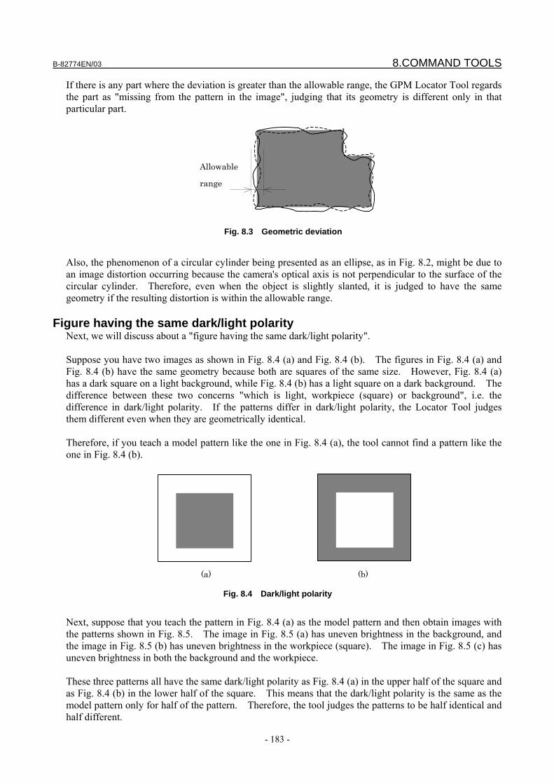
B-82774EN/03 8.COMMAND TOOLS
- 183 -
If there is any part where the deviation is greater than the allowable range, the GPM Locator Tool regards the part as "missing from the pattern in the image", judging that its geometry is different only in that particular part.
Allowable
range
Fig. 8.3 Geometric deviation
Also, the phenomenon of a circular cylinder being presented as an ellipse, as in Fig. 8.2, might be due to an image distortion occurring because the camera's optical axis is not perpendicular to the surface of the circular cylinder. Therefore, even when the object is slightly slanted, it is judged to have the same geometry if the resulting distortion is within the allowable range.
Figure having the same dark/light polarity Next, we will discuss about a "figure having the same dark/light polarity". Suppose you have two images as shown in Fig. 8.4 (a) and Fig. 8.4 (b). The figures in Fig. 8.4 (a) and Fig. 8.4 (b) have the same geometry because both are squares of the same size. However, Fig. 8.4 (a) has a dark square on a light background, while Fig. 8.4 (b) has a light square on a dark background. The difference between these two concerns "which is light, workpiece (square) or background", i.e. the difference in dark/light polarity. If the patterns differ in dark/light polarity, the Locator Tool judges them different even when they are geometrically identical. Therefore, if you teach a model pattern like the one in Fig. 8.4 (a), the tool cannot find a pattern like the one in Fig. 8.4 (b).
(a) (b)
Fig. 8.4 Dark/light polarity
Next, suppose that you teach the pattern in Fig. 8.4 (a) as the model pattern and then obtain images with the patterns shown in Fig. 8.5. The image in Fig. 8.5 (a) has uneven brightness in the background, and the image in Fig. 8.5 (b) has uneven brightness in the workpiece (square). The image in Fig. 8.5 (c) has uneven brightness in both the background and the workpiece. These three patterns all have the same dark/light polarity as Fig. 8.4 (a) in the upper half of the square and as Fig. 8.4 (b) in the lower half of the square. This means that the dark/light polarity is the same as the model pattern only for half of the pattern. Therefore, the tool judges the patterns to be half identical and half different.
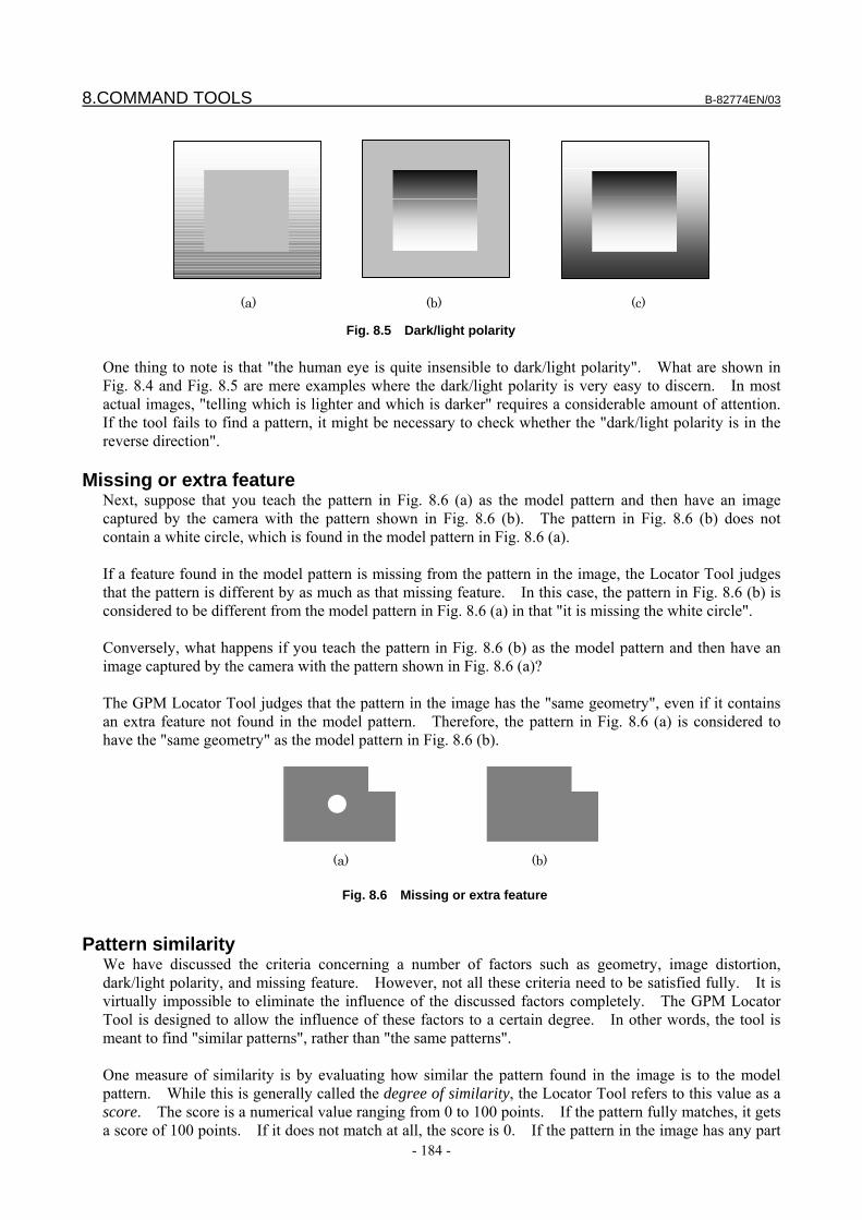
8.COMMAND TOOLS B-82774EN/03
- 184 -
(a) (b) (c)
Fig. 8.5 Dark/light polarity
One thing to note is that "the human eye is quite insensible to dark/light polarity". What are shown in Fig. 8.4 and Fig. 8.5 are mere examples where the dark/light polarity is very easy to discern. In most actual images, "telling which is lighter and which is darker" requires a considerable amount of attention. If the tool fails to find a pattern, it might be necessary to check whether the "dark/light polarity is in the reverse direction".
Missing or extra feature Next, suppose that you teach the pattern in Fig. 8.6 (a) as the model pattern and then have an image captured by the camera with the pattern shown in Fig. 8.6 (b). The pattern in Fig. 8.6 (b) does not contain a white circle, which is found in the model pattern in Fig. 8.6 (a). If a feature found in the model pattern is missing from the pattern in the image, the Locator Tool judges that the pattern is different by as much as that missing feature. In this case, the pattern in Fig. 8.6 (b) is considered to be different from the model pattern in Fig. 8.6 (a) in that "it is missing the white circle". Conversely, what happens if you teach the pattern in Fig. 8.6 (b) as the model pattern and then have an image captured by the camera with the pattern shown in Fig. 8.6 (a)? The GPM Locator Tool judges that the pattern in the image has the "same geometry", even if it contains an extra feature not found in the model pattern. Therefore, the pattern in Fig. 8.6 (a) is considered to have the "same geometry" as the model pattern in Fig. 8.6 (b).
(a) (b)
Fig. 8.6 Missing or extra feature
Pattern similarity
We have discussed the criteria concerning a number of factors such as geometry, image distortion, dark/light polarity, and missing feature. However, not all these criteria need to be satisfied fully. It is virtually impossible to eliminate the influence of the discussed factors completely. The GPM Locator Tool is designed to allow the influence of these factors to a certain degree. In other words, the tool is meant to find "similar patterns", rather than "the same patterns". One measure of similarity is by evaluating how similar the pattern found in the image is to the model pattern. While this is generally called the degree of similarity, the Locator Tool refers to this value as a score. The score is a numerical value ranging from 0 to 100 points. If the pattern fully matches, it gets a score of 100 points. If it does not match at all, the score is 0. If the pattern in the image has any part
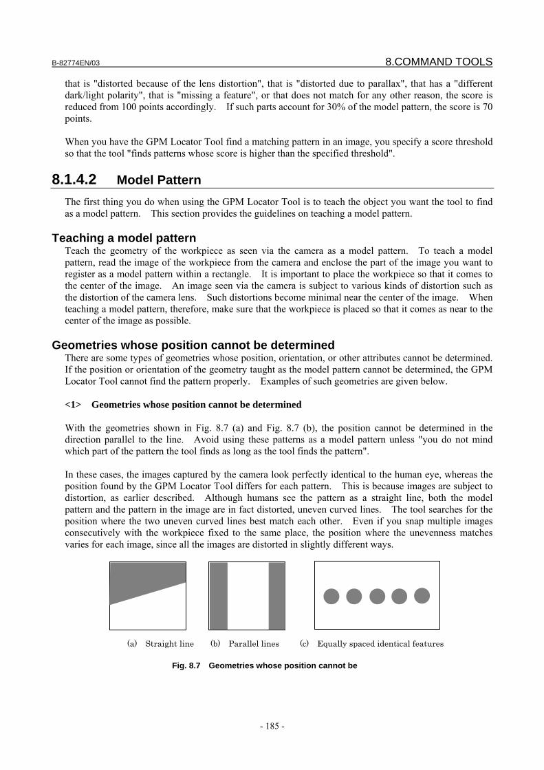
B-82774EN/03 8.COMMAND TOOLS
- 185 -
that is "distorted because of the lens distortion", that is "distorted due to parallax", that has a "different dark/light polarity", that is "missing a feature", or that does not match for any other reason, the score is reduced from 100 points accordingly. If such parts account for 30% of the model pattern, the score is 70 points. When you have the GPM Locator Tool find a matching pattern in an image, you specify a score threshold so that the tool "finds patterns whose score is higher than the specified threshold".
8.1.4.2 Model Pattern The first thing you do when using the GPM Locator Tool is to teach the object you want the tool to find as a model pattern. This section provides the guidelines on teaching a model pattern.
Teaching a model pattern Teach the geometry of the workpiece as seen via the camera as a model pattern. To teach a model pattern, read the image of the workpiece from the camera and enclose the part of the image you want to register as a model pattern within a rectangle. It is important to place the workpiece so that it comes to the center of the image. An image seen via the camera is subject to various kinds of distortion such as the distortion of the camera lens. Such distortions become minimal near the center of the image. When teaching a model pattern, therefore, make sure that the workpiece is placed so that it comes as near to the center of the image as possible.
Geometries whose position cannot be determined There are some types of geometries whose position, orientation, or other attributes cannot be determined. If the position or orientation of the geometry taught as the model pattern cannot be determined, the GPM Locator Tool cannot find the pattern properly. Examples of such geometries are given below. <1> Geometries whose position cannot be determined With the geometries shown in Fig. 8.7 (a) and Fig. 8.7 (b), the position cannot be determined in the direction parallel to the line. Avoid using these patterns as a model pattern unless "you do not mind which part of the pattern the tool finds as long as the tool finds the pattern". In these cases, the images captured by the camera look perfectly identical to the human eye, whereas the position found by the GPM Locator Tool differs for each pattern. This is because images are subject to distortion, as earlier described. Although humans see the pattern as a straight line, both the model pattern and the pattern in the image are in fact distorted, uneven curved lines. The tool searches for the position where the two uneven curved lines best match each other. Even if you snap multiple images consecutively with the workpiece fixed to the same place, the position where the unevenness matches varies for each image, since all the images are distorted in slightly different ways.
(a) Straight line (b) Parallel lines (c) Equally spaced identical features
Fig. 8.7 Geometries whose position cannot be
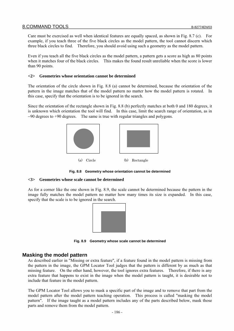
8.COMMAND TOOLS B-82774EN/03
- 186 -
Care must be exercised as well when identical features are equally spaced, as shown in Fig. 8.7 (c). For example, if you teach three of the five black circles as the model pattern, the tool cannot discern which three black circles to find. Therefore, you should avoid using such a geometry as the model pattern. Even if you teach all the five black circles as the model pattern, a pattern gets a score as high as 80 points when it matches four of the black circles. This makes the found result unreliable when the score is lower than 90 points. <2> Geometries whose orientation cannot be determined The orientation of the circle shown in Fig. 8.8 (a) cannot be determined, because the orientation of the pattern in the image matches that of the model pattern no matter how the model pattern is rotated. In this case, specify that the orientation is to be ignored in the search. Since the orientation of the rectangle shown in Fig. 8.8 (b) perfectly matches at both 0 and 180 degrees, it is unknown which orientation the tool will find. In this case, limit the search range of orientation, as in −90 degrees to +90 degrees. The same is true with regular triangles and polygons.
(a) Circle (b) Rectangle
Fig. 8.8 Geometry whose orientation cannot be determined
<3> Geometries whose scale cannot be determined As for a corner like the one shown in Fig. 8.9, the scale cannot be determined because the pattern in the image fully matches the model pattern no matter how many times its size is expanded. In this case, specify that the scale is to be ignored in the search.
Fig. 8.9 Geometry whose scale cannot be determined
Masking the model pattern
As described earlier in "Missing or extra feature", if a feature found in the model pattern is missing from the pattern in the image, the GPM Locator Tool judges that the pattern is different by as much as that missing feature. On the other hand, however, the tool ignores extra features. Therefore, if there is any extra feature that happens to exist in the image when the model pattern is taught, it is desirable not to include that feature in the model pattern. The GPM Locator Tool allows you to mask a specific part of the image and to remove that part from the model pattern after the model pattern teaching operation. This process is called "masking the model pattern". If the image taught as a model pattern includes any of the parts described below, mask those parts and remove them from the model pattern.
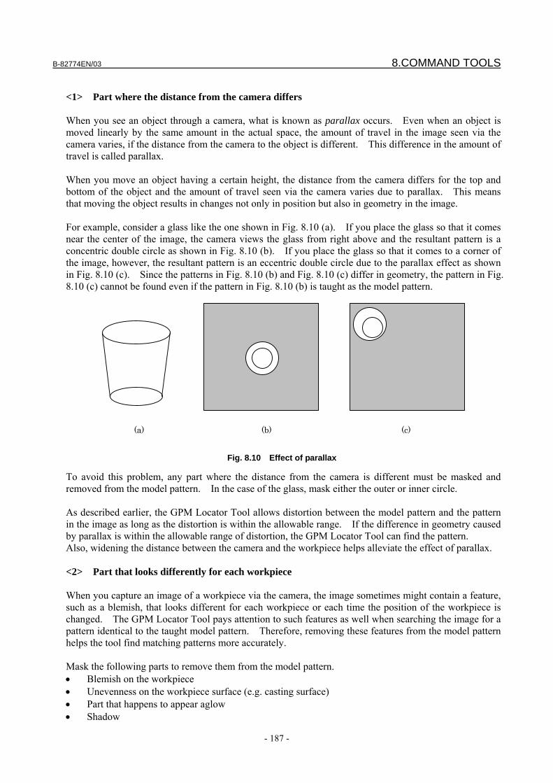
B-82774EN/03 8.COMMAND TOOLS
- 187 -
<1> Part where the distance from the camera differs When you see an object through a camera, what is known as parallax occurs. Even when an object is moved linearly by the same amount in the actual space, the amount of travel in the image seen via the camera varies, if the distance from the camera to the object is different. This difference in the amount of travel is called parallax. When you move an object having a certain height, the distance from the camera differs for the top and bottom of the object and the amount of travel seen via the camera varies due to parallax. This means that moving the object results in changes not only in position but also in geometry in the image. For example, consider a glass like the one shown in Fig. 8.10 (a). If you place the glass so that it comes near the center of the image, the camera views the glass from right above and the resultant pattern is a concentric double circle as shown in Fig. 8.10 (b). If you place the glass so that it comes to a corner of the image, however, the resultant pattern is an eccentric double circle due to the parallax effect as shown in Fig. 8.10 (c). Since the patterns in Fig. 8.10 (b) and Fig. 8.10 (c) differ in geometry, the pattern in Fig. 8.10 (c) cannot be found even if the pattern in Fig. 8.10 (b) is taught as the model pattern.
(a) (b) (c)
Fig. 8.10 Effect of parallax
To avoid this problem, any part where the distance from the camera is different must be masked and removed from the model pattern. In the case of the glass, mask either the outer or inner circle. As described earlier, the GPM Locator Tool allows distortion between the model pattern and the pattern in the image as long as the distortion is within the allowable range. If the difference in geometry caused by parallax is within the allowable range of distortion, the GPM Locator Tool can find the pattern. Also, widening the distance between the camera and the workpiece helps alleviate the effect of parallax. <2> Part that looks differently for each workpiece When you capture an image of a workpiece via the camera, the image sometimes might contain a feature, such as a blemish, that looks different for each workpiece or each time the position of the workpiece is changed. The GPM Locator Tool pays attention to such features as well when searching the image for a pattern identical to the taught model pattern. Therefore, removing these features from the model pattern helps the tool find matching patterns more accurately. Mask the following parts to remove them from the model pattern. • Blemish on the workpiece • Unevenness on the workpiece surface (e.g. casting surface) • Part that happens to appear aglow • Shadow
8.COMMAND TOOLS B-82774EN/03
- 188 -
• Hand-written letters and marks • Label <3> Part where dark/light polarity is irregular When the position or orientation of an object is changed, the way the object is illuminated and how shadows are cast on it might change as well, thus altering the dark/light polarity of the figure in the image. As described earlier, the GPM Locator Tool considers a pattern different if its dark/light polarity is different. When you snap images of actual workpieces, it is often the case that the dark/light polarity appears reversed in some parts of the pattern although the overall dark/light polarity of the pattern remains unchanged. These parts look different for each workpiece, as described in <2>, and removing them from the model pattern helps the tool find matching patterns more accurately.
Other points to note Basically, the more complex the geometry you teach as the model pattern is, the more stable the found result becomes. For example, a small circle is often difficult to be distinguished from a blemish. When the model pattern has a complex geometry, it is very unlikely that an unintended object happens to look like it. Masking the model pattern excessively might draw you into the pitfall described above. If you mask too many parts of the model pattern, you can end up with a pattern having a very simple geometry, causing the tool to find an "unintended object" that happens to be included in the image. Or, the model pattern you teach might have a "geometry whose position or orientation cannot be determined".
8.1.4.3 Found Pattern This section explains about the pattern found by the Locator Tool.
Position of the found pattern When the GPM Locator Tool finds a pattern identical to the model pattern in the image, it outputs the coordinates of the "model origin" of that found pattern as the "position of the pattern". You can set the position of the model origin anywhere you like. When you initially teach the model pattern, the model origin is positioned in the center of the rectangle you use for teaching the model pattern. No matter where you set the model origin, the probability of finding and the location accuracy of the GPM Locator Tool will not be affected. If you change the position of the model origin, the tool outputs different coordinates even when it finds a pattern at the same position in the image. Changing the position of the model origin after setting the reference position makes it impossible to perform robot position offset normally. Note that, after you change the position of the model origin, you need to change the reference position and the taught robot position accordingly.
Orientation and scale of the found pattern When the GPM Locator Tool finds a pattern identical to the model pattern in the image, it outputs the orientation and scale of the found pattern relative to the model pattern as Orientation and Scale. The orientation of the found pattern indicates by how many degrees it is rotated with respect to the model pattern. The scale of the found pattern shows how many times it is expanded with respect to the model pattern.
B-82774EN/03 8.COMMAND TOOLS
- 189 -
Score of the found pattern The GPM Locator Tool represents how similar the pattern found in the image is to the model pattern, by using an evaluation value called score. The score is a numerical value ranging from 0 to 100 points. If the pattern fully matches, it gets a score of 100 points. If it does not match at all, the score is 0. For example, a score of 70 points indicates that the pattern in the image is 30% different from the model pattern because it has parts that are "hidden beneath other objects", that are "invisible due to halation", that are "distorted because of the lens distortion", that are "distorted due to parallax", that have a "different dark/light polarity", etc. To judge whether proper values are obtained, repeat the find test while changing the position and orientation of the workpiece in the image. The desirable situation is where you constantly get a score of over 70 points, preferably 80 points or more. If this is not the case, check the following: • Whether the lens is dirty • Whether the lens is in focus • Whether the lens diaphragm is properly adjusted • Whether the type of lighting is adequate • Whether the brightness of lighting is properly adjusted • Whether the points described in "Masking the model pattern" are followed
Elasticity of the found pattern The GPM Locator Tool represents how much the pattern found in the image is distorted with relation to the model pattern, by using an evaluation value called elasticity. The elasticity is 0 pixels if the found pattern fully matches the model pattern. The value will be 0.4 pixels if "some parts of the found pattern fully match and some parts are deviated by 1 pixel with an average deviation of 0.4 pixels". The smaller the value is, the less distorted the found pattern is with relation to the model pattern. To judge whether proper values are obtained, repeat the find test while changing the position and orientation of the workpiece in the image. The desirable situation is where you constantly get an elasticity value of below 1.0 pixel, preferably 0.5 pixels or less. If this is not the case, check the following: • Whether the lens is in focus • Whether the lens diaphragm is properly adjusted • Whether the type of lighting is adequate • Whether the brightness of lighting is properly adjusted • Whether the points described in "Masking the model pattern" are followed
Contrast of the found pattern In addition to score and elasticity, there is one more evaluation value that the GPM Locator Tool finds - contrast. This value represents "how clearly the pattern found in the image can be seen". The value of contrast ranges from 1 to 255. The larger the value, the clearer the pattern. Contrast is irrelevant to "whether the pattern is identical to the model pattern". For example, take the ellipses shown in Fig. 8.11 (a) and Fig. 8.11 (b). Since the ellipse in Fig. 8.11 (a) is seen clearly, it has a higher contrast value than the one in Fig. 8.11 (b). Still, these ellipses get the same score because their geometry and dark/light polarity are the same. However, if any part of the ellipse in Fig. 8.11 (b) is invisible because of low contrast, the pattern's score is reduced as much.
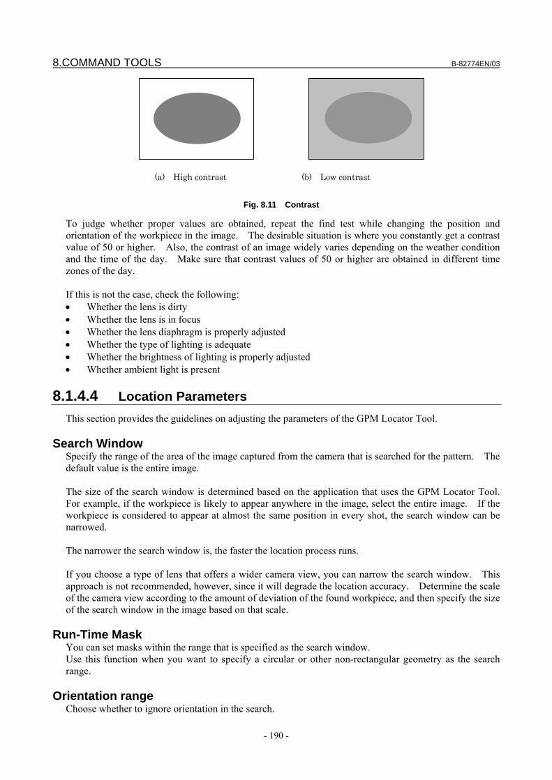
8.COMMAND TOOLS B-82774EN/03
- 190 -
(a) High contrast (b) Low contrast
Fig. 8.11 Contrast
To judge whether proper values are obtained, repeat the find test while changing the position and orientation of the workpiece in the image. The desirable situation is where you constantly get a contrast value of 50 or higher. Also, the contrast of an image widely varies depending on the weather condition and the time of the day. Make sure that contrast values of 50 or higher are obtained in different time zones of the day. If this is not the case, check the following: • Whether the lens is dirty • Whether the lens is in focus • Whether the lens diaphragm is properly adjusted • Whether the type of lighting is adequate • Whether the brightness of lighting is properly adjusted • Whether ambient light is present
8.1.4.4 Location Parameters This section provides the guidelines on adjusting the parameters of the GPM Locator Tool.
Search Window Specify the range of the area of the image captured from the camera that is searched for the pattern. The default value is the entire image. The size of the search window is determined based on the application that uses the GPM Locator Tool. For example, if the workpiece is likely to appear anywhere in the image, select the entire image. If the workpiece is considered to appear at almost the same position in every shot, the search window can be narrowed. The narrower the search window is, the faster the location process runs. If you choose a type of lens that offers a wider camera view, you can narrow the search window. This approach is not recommended, however, since it will degrade the location accuracy. Determine the scale of the camera view according to the amount of deviation of the found workpiece, and then specify the size of the search window in the image based on that scale.
Run-Time Mask You can set masks within the range that is specified as the search window. Use this function when you want to specify a circular or other non-rectangular geometry as the search range.
Orientation range Choose whether to ignore orientation in the search.
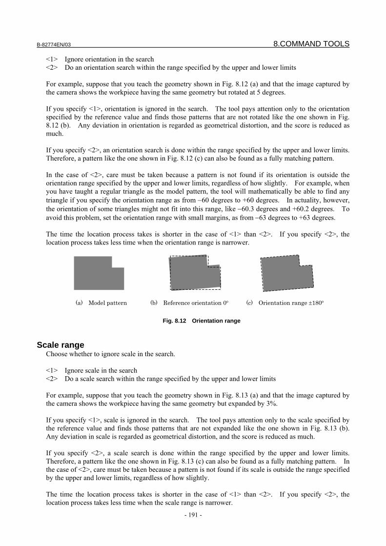
B-82774EN/03 8.COMMAND TOOLS
- 191 -
<1> Ignore orientation in the search <2> Do an orientation search within the range specified by the upper and lower limits For example, suppose that you teach the geometry shown in Fig. 8.12 (a) and that the image captured by the camera shows the workpiece having the same geometry but rotated at 5 degrees. If you specify <1>, orientation is ignored in the search. The tool pays attention only to the orientation specified by the reference value and finds those patterns that are not rotated like the one shown in Fig. 8.12 (b). Any deviation in orientation is regarded as geometrical distortion, and the score is reduced as much. If you specify <2>, an orientation search is done within the range specified by the upper and lower limits. Therefore, a pattern like the one shown in Fig. 8.12 (c) can also be found as a fully matching pattern. In the case of <2>, care must be taken because a pattern is not found if its orientation is outside the orientation range specified by the upper and lower limits, regardless of how slightly. For example, when you have taught a regular triangle as the model pattern, the tool will mathematically be able to find any triangle if you specify the orientation range as from −60 degrees to +60 degrees. In actuality, however, the orientation of some triangles might not fit into this range, like −60.3 degrees and +60.2 degrees. To avoid this problem, set the orientation range with small margins, as from −63 degrees to +63 degrees. The time the location process takes is shorter in the case of <1> than <2>. If you specify <2>, the location process takes less time when the orientation range is narrower.
(a) Model pattern (b) Reference orientation 0° (c) Orientation range ±180°
Fig. 8.12 Orientation range
Scale range
Choose whether to ignore scale in the search. <1> Ignore scale in the search <2> Do a scale search within the range specified by the upper and lower limits For example, suppose that you teach the geometry shown in Fig. 8.13 (a) and that the image captured by the camera shows the workpiece having the same geometry but expanded by 3%. If you specify <1>, scale is ignored in the search. The tool pays attention only to the scale specified by the reference value and finds those patterns that are not expanded like the one shown in Fig. 8.13 (b). Any deviation in scale is regarded as geometrical distortion, and the score is reduced as much. If you specify <2>, a scale search is done within the range specified by the upper and lower limits. Therefore, a pattern like the one shown in Fig. 8.13 (c) can also be found as a fully matching pattern. In the case of <2>, care must be taken because a pattern is not found if its scale is outside the range specified by the upper and lower limits, regardless of how slightly. The time the location process takes is shorter in the case of <1> than <2>. If you specify <2>, the location process takes less time when the scale range is narrower.
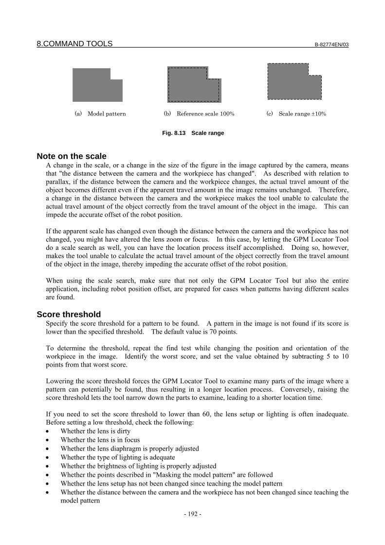
8.COMMAND TOOLS B-82774EN/03
- 192 -
(a) Model pattern (b) Reference scale 100% (c) Scale range ±10%
Fig. 8.13 Scale range
Note on the scale
A change in the scale, or a change in the size of the figure in the image captured by the camera, means that "the distance between the camera and the workpiece has changed". As described with relation to parallax, if the distance between the camera and the workpiece changes, the actual travel amount of the object becomes different even if the apparent travel amount in the image remains unchanged. Therefore, a change in the distance between the camera and the workpiece makes the tool unable to calculate the actual travel amount of the object correctly from the travel amount of the object in the image. This can impede the accurate offset of the robot position. If the apparent scale has changed even though the distance between the camera and the workpiece has not changed, you might have altered the lens zoom or focus. In this case, by letting the GPM Locator Tool do a scale search as well, you can have the location process itself accomplished. Doing so, however, makes the tool unable to calculate the actual travel amount of the object correctly from the travel amount of the object in the image, thereby impeding the accurate offset of the robot position. When using the scale search, make sure that not only the GPM Locator Tool but also the entire application, including robot position offset, are prepared for cases when patterns having different scales are found.
Score threshold Specify the score threshold for a pattern to be found. A pattern in the image is not found if its score is lower than the specified threshold. The default value is 70 points. To determine the threshold, repeat the find test while changing the position and orientation of the workpiece in the image. Identify the worst score, and set the value obtained by subtracting 5 to 10 points from that worst score. Lowering the score threshold forces the GPM Locator Tool to examine many parts of the image where a pattern can potentially be found, thus resulting in a longer location process. Conversely, raising the score threshold lets the tool narrow down the parts to examine, leading to a shorter location time. If you need to set the score threshold to lower than 60, the lens setup or lighting is often inadequate. Before setting a low threshold, check the following: • Whether the lens is dirty • Whether the lens is in focus • Whether the lens diaphragm is properly adjusted • Whether the type of lighting is adequate • Whether the brightness of lighting is properly adjusted • Whether the points described in "Masking the model pattern" are followed • Whether the lens setup has not been changed since teaching the model pattern • Whether the distance between the camera and the workpiece has not been changed since teaching the
model pattern
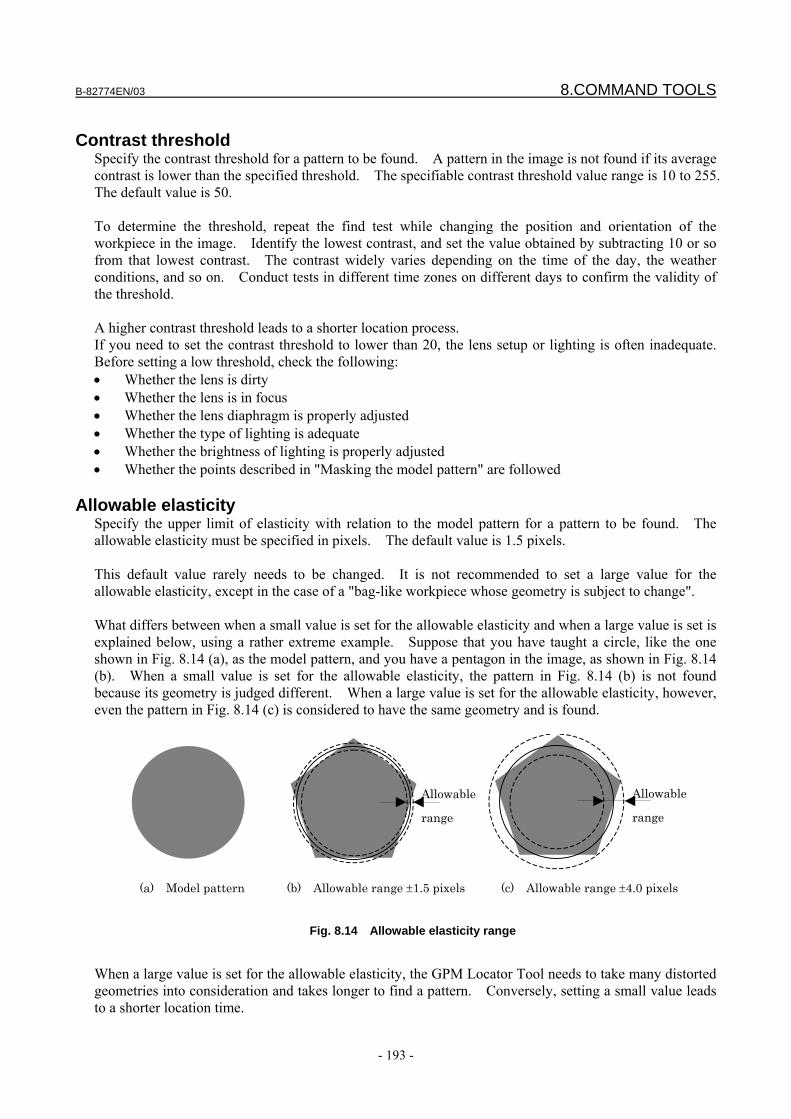
B-82774EN/03 8.COMMAND TOOLS
- 193 -
Contrast threshold
Specify the contrast threshold for a pattern to be found. A pattern in the image is not found if its average contrast is lower than the specified threshold. The specifiable contrast threshold value range is 10 to 255. The default value is 50. To determine the threshold, repeat the find test while changing the position and orientation of the workpiece in the image. Identify the lowest contrast, and set the value obtained by subtracting 10 or so from that lowest contrast. The contrast widely varies depending on the time of the day, the weather conditions, and so on. Conduct tests in different time zones on different days to confirm the validity of the threshold. A higher contrast threshold leads to a shorter location process. If you need to set the contrast threshold to lower than 20, the lens setup or lighting is often inadequate. Before setting a low threshold, check the following: • Whether the lens is dirty • Whether the lens is in focus • Whether the lens diaphragm is properly adjusted • Whether the type of lighting is adequate • Whether the brightness of lighting is properly adjusted • Whether the points described in "Masking the model pattern" are followed
Allowable elasticity Specify the upper limit of elasticity with relation to the model pattern for a pattern to be found. The allowable elasticity must be specified in pixels. The default value is 1.5 pixels. This default value rarely needs to be changed. It is not recommended to set a large value for the allowable elasticity, except in the case of a "bag-like workpiece whose geometry is subject to change". What differs between when a small value is set for the allowable elasticity and when a large value is set is explained below, using a rather extreme example. Suppose that you have taught a circle, like the one shown in Fig. 8.14 (a), as the model pattern, and you have a pentagon in the image, as shown in Fig. 8.14 (b). When a small value is set for the allowable elasticity, the pattern in Fig. 8.14 (b) is not found because its geometry is judged different. When a large value is set for the allowable elasticity, however, even the pattern in Fig. 8.14 (c) is considered to have the same geometry and is found.
Allowable
range
Allowable
range
(a) Model pattern (b) Allowable range ±1.5 pixels (c) Allowable range ±4.0 pixels
Fig. 8.14 Allowable elasticity range
When a large value is set for the allowable elasticity, the GPM Locator Tool needs to take many distorted geometries into consideration and takes longer to find a pattern. Conversely, setting a small value leads to a shorter location time.
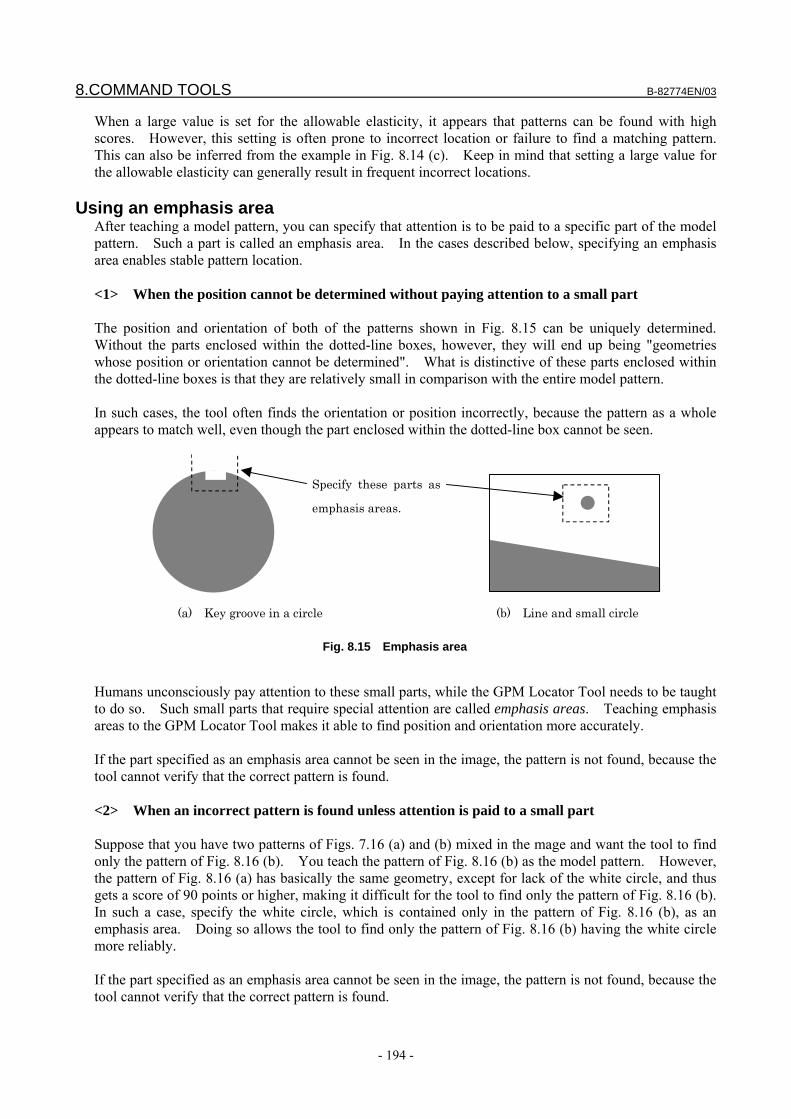
8.COMMAND TOOLS B-82774EN/03
- 194 -
When a large value is set for the allowable elasticity, it appears that patterns can be found with high scores. However, this setting is often prone to incorrect location or failure to find a matching pattern. This can also be inferred from the example in Fig. 8.14 (c). Keep in mind that setting a large value for the allowable elasticity can generally result in frequent incorrect locations.
Using an emphasis area After teaching a model pattern, you can specify that attention is to be paid to a specific part of the model pattern. Such a part is called an emphasis area. In the cases described below, specifying an emphasis area enables stable pattern location. <1> When the position cannot be determined without paying attention to a small part The position and orientation of both of the patterns shown in Fig. 8.15 can be uniquely determined. Without the parts enclosed within the dotted-line boxes, however, they will end up being "geometries whose position or orientation cannot be determined". What is distinctive of these parts enclosed within the dotted-line boxes is that they are relatively small in comparison with the entire model pattern. In such cases, the tool often finds the orientation or position incorrectly, because the pattern as a whole appears to match well, even though the part enclosed within the dotted-line box cannot be seen.
Specify these parts as
emphasis areas.
(a) Key groove in a circle (b) Line and small circle
Fig. 8.15 Emphasis area
Humans unconsciously pay attention to these small parts, while the GPM Locator Tool needs to be taught to do so. Such small parts that require special attention are called emphasis areas. Teaching emphasis areas to the GPM Locator Tool makes it able to find position and orientation more accurately. If the part specified as an emphasis area cannot be seen in the image, the pattern is not found, because the tool cannot verify that the correct pattern is found. <2> When an incorrect pattern is found unless attention is paid to a small part Suppose that you have two patterns of Figs. 7.16 (a) and (b) mixed in the mage and want the tool to find only the pattern of Fig. 8.16 (b). You teach the pattern of Fig. 8.16 (b) as the model pattern. However, the pattern of Fig. 8.16 (a) has basically the same geometry, except for lack of the white circle, and thus gets a score of 90 points or higher, making it difficult for the tool to find only the pattern of Fig. 8.16 (b). In such a case, specify the white circle, which is contained only in the pattern of Fig. 8.16 (b), as an emphasis area. Doing so allows the tool to find only the pattern of Fig. 8.16 (b) having the white circle more reliably. If the part specified as an emphasis area cannot be seen in the image, the pattern is not found, because the tool cannot verify that the correct pattern is found.
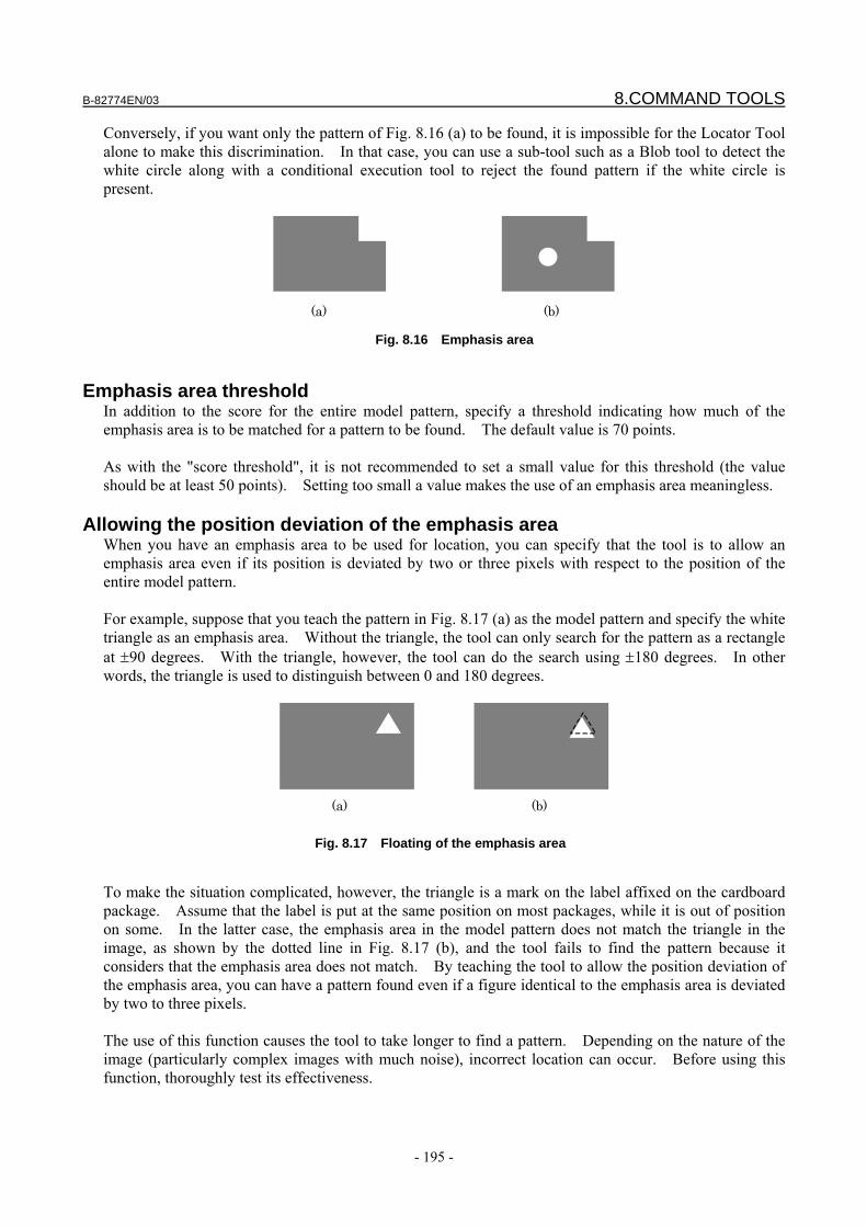
B-82774EN/03 8.COMMAND TOOLS
- 195 -
Conversely, if you want only the pattern of Fig. 8.16 (a) to be found, it is impossible for the Locator Tool alone to make this discrimination. In that case, you can use a sub-tool such as a Blob tool to detect the white circle along with a conditional execution tool to reject the found pattern if the white circle is present.
(a) (b)
Fig. 8.16 Emphasis area
Emphasis area threshold
In addition to the score for the entire model pattern, specify a threshold indicating how much of the emphasis area is to be matched for a pattern to be found. The default value is 70 points. As with the "score threshold", it is not recommended to set a small value for this threshold (the value should be at least 50 points). Setting too small a value makes the use of an emphasis area meaningless.
Allowing the position deviation of the emphasis area When you have an emphasis area to be used for location, you can specify that the tool is to allow an emphasis area even if its position is deviated by two or three pixels with respect to the position of the entire model pattern. For example, suppose that you teach the pattern in Fig. 8.17 (a) as the model pattern and specify the white triangle as an emphasis area. Without the triangle, the tool can only search for the pattern as a rectangle at ±90 degrees. With the triangle, however, the tool can do the search using ±180 degrees. In other words, the triangle is used to distinguish between 0 and 180 degrees.
(a) (b)
Fig. 8.17 Floating of the emphasis area
To make the situation complicated, however, the triangle is a mark on the label affixed on the cardboard package. Assume that the label is put at the same position on most packages, while it is out of position on some. In the latter case, the emphasis area in the model pattern does not match the triangle in the image, as shown by the dotted line in Fig. 8.17 (b), and the tool fails to find the pattern because it considers that the emphasis area does not match. By teaching the tool to allow the position deviation of the emphasis area, you can have a pattern found even if a figure identical to the emphasis area is deviated by two to three pixels. The use of this function causes the tool to take longer to find a pattern. Depending on the nature of the image (particularly complex images with much noise), incorrect location can occur. Before using this function, thoroughly test its effectiveness.
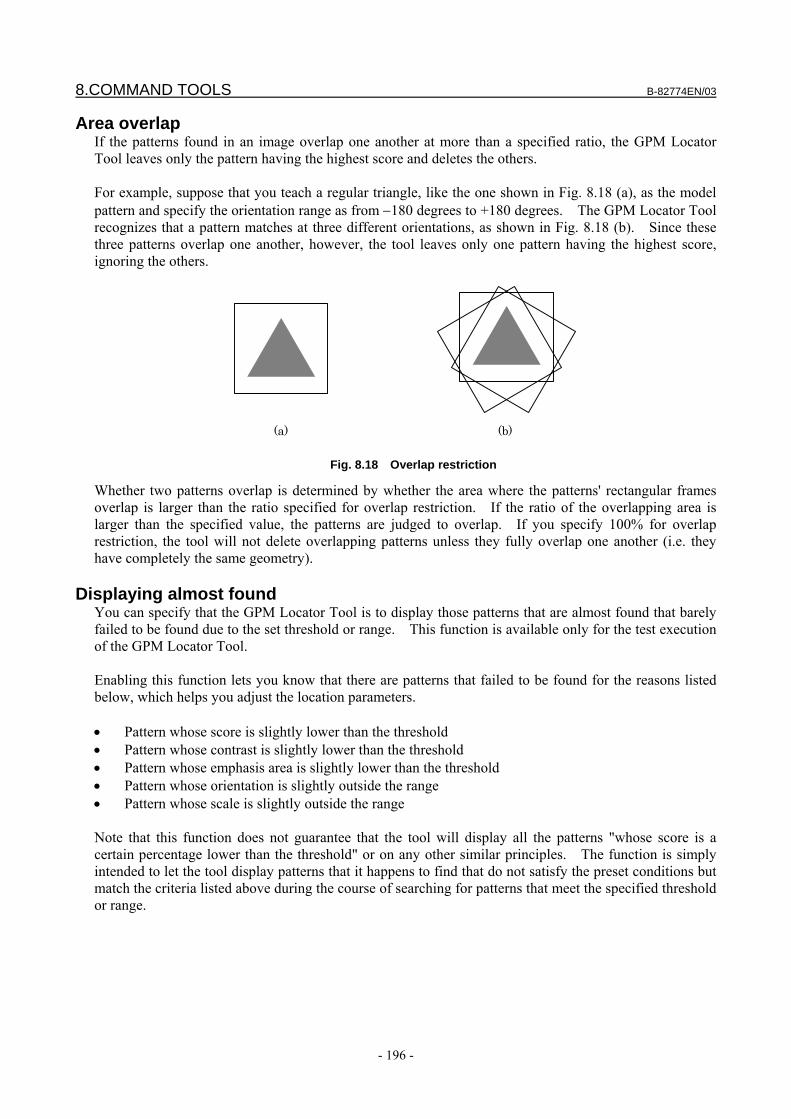
8.COMMAND TOOLS B-82774EN/03
- 196 -
Area overlap If the patterns found in an image overlap one another at more than a specified ratio, the GPM Locator Tool leaves only the pattern having the highest score and deletes the others. For example, suppose that you teach a regular triangle, like the one shown in Fig. 8.18 (a), as the model pattern and specify the orientation range as from −180 degrees to +180 degrees. The GPM Locator Tool recognizes that a pattern matches at three different orientations, as shown in Fig. 8.18 (b). Since these three patterns overlap one another, however, the tool leaves only one pattern having the highest score, ignoring the others.
(a) (b)
Fig. 8.18 Overlap restriction
Whether two patterns overlap is determined by whether the area where the patterns' rectangular frames overlap is larger than the ratio specified for overlap restriction. If the ratio of the overlapping area is larger than the specified value, the patterns are judged to overlap. If you specify 100% for overlap restriction, the tool will not delete overlapping patterns unless they fully overlap one another (i.e. they have completely the same geometry).
Displaying almost found You can specify that the GPM Locator Tool is to display those patterns that are almost found that barely failed to be found due to the set threshold or range. This function is available only for the test execution of the GPM Locator Tool. Enabling this function lets you know that there are patterns that failed to be found for the reasons listed below, which helps you adjust the location parameters. • Pattern whose score is slightly lower than the threshold • Pattern whose contrast is slightly lower than the threshold • Pattern whose emphasis area is slightly lower than the threshold • Pattern whose orientation is slightly outside the range • Pattern whose scale is slightly outside the range Note that this function does not guarantee that the tool will display all the patterns "whose score is a certain percentage lower than the threshold" or on any other similar principles. The function is simply intended to let the tool display patterns that it happens to find that do not satisfy the preset conditions but match the criteria listed above during the course of searching for patterns that meet the specified threshold or range.
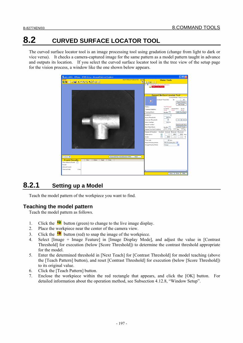
B-82774EN/03 8.COMMAND TOOLS
- 197 -
8.2 CURVED SURFACE LOCATOR TOOL The curved surface locator tool is an image processing tool using gradation (change from light to dark or vice versa). It checks a camera-captured image for the same pattern as a model pattern taught in advance and outputs its location. If you select the curved surface locator tool in the tree view of the setup page for the vision process, a window like the one shown below appears.
8.2.1 Setting up a Model Teach the model pattern of the workpiece you want to find.
Teaching the model pattern Teach the model pattern as follows. 1. Click the button (green) to change to the live image display. 2. Place the workpiece near the center of the camera view. 3. Click the button (red) to snap the image of the workpiece. 4. Select [Image + Image Feature] in [Image Display Mode], and adjust the value in [Contrast
Threshold] for execution (below [Score Threshold]) to determine the contrast threshold appropriate for the model.
5. Enter the determined threshold in [Next Teach] for [Contrast Threshold] for model teaching (above the [Teach Pattern] button), and reset [Contrast Threshold] for execution (below [Score Threshold]) to its original value.
6. Click the [Teach Pattern] button. 7. Enclose the workpiece within the red rectangle that appears, and click the [OK] button. For
detailed information about the operation method, see Subsection 4.12.8, “Window Setup”.
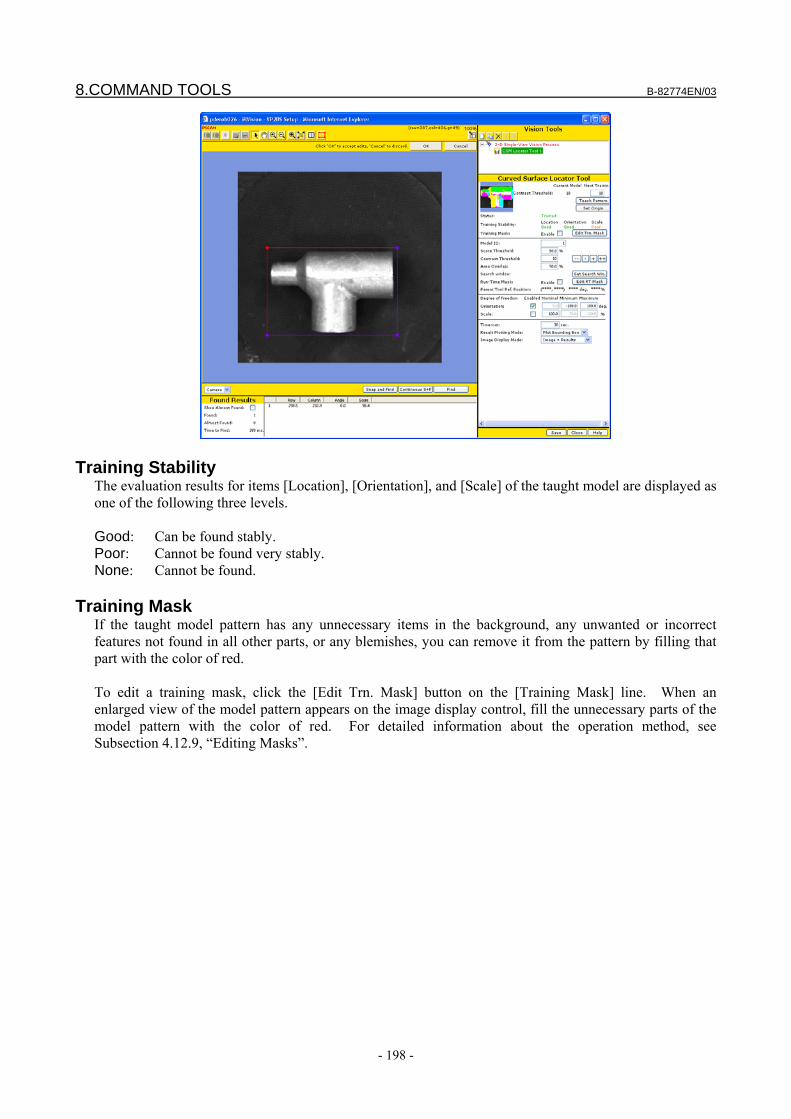
8.COMMAND TOOLS B-82774EN/03
- 198 -
Training Stability The evaluation results for items [Location], [Orientation], and [Scale] of the taught model are displayed as one of the following three levels. Good: Can be found stably. Poor: Cannot be found very stably. None: Cannot be found.
Training Mask If the taught model pattern has any unnecessary items in the background, any unwanted or incorrect features not found in all other parts, or any blemishes, you can remove it from the pattern by filling that part with the color of red. To edit a training mask, click the [Edit Trn. Mask] button on the [Training Mask] line. When an enlarged view of the model pattern appears on the image display control, fill the unnecessary parts of the model pattern with the color of red. For detailed information about the operation method, see Subsection 4.12.9, “Editing Masks”.
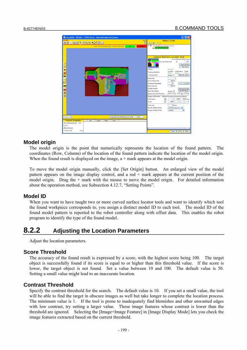
B-82774EN/03 8.COMMAND TOOLS
- 199 -
Model origin The model origin is the point that numerically represents the location of the found pattern. The coordinates (Row, Column) of the location of the found pattern indicate the location of the model origin. When the found result is displayed on the image, a + mark appears at the model origin. To move the model origin manually, click the [Set Origin] button. An enlarged view of the model pattern appears on the image display control, and a red + mark appears at the current position of the model origin. Drag the + mark with the mouse to move the model origin. For detailed information about the operation method, see Subsection 4.12.7, “Setting Points”.
Model ID When you want to have taught two or more curved surface locator tools and want to identify which tool the found workpiece corresponds to, you assign a distinct model ID to each tool. The model ID of the found model pattern is reported to the robot controller along with offset data. This enables the robot program to identify the type of the found model.
8.2.2 Adjusting the Location Parameters Adjust the location parameters.
Score Threshold The accuracy of the found result is expressed by a score, with the highest score being 100. The target object is successfully found if its score is equal to or higher than this threshold value. If the score is lower, the target object is not found. Set a value between 10 and 100. The default value is 50. Setting a small value might lead to an inaccurate location.
Contrast Threshold Specify the contrast threshold for the search. The default value is 10. If you set a small value, the tool will be able to find the target in obscure images as well but take longer to complete the location process. The minimum value is 1. If the tool is prone to inadequately find blemishes and other unwanted edges with low contrast, try setting a larger value. Those image features whose contrast is lower than the threshold are ignored. Selecting the [Image+Image Feature] in [Image Display Mode] lets you check the image features extracted based on the current threshold.

8.COMMAND TOOLS B-82774EN/03
- 200 -
Area Overlap If the ratio of overlap of the found objects is higher than the ratio specified here, then the found result for the workpiece with the lower score is deleted, leaving only the one with the higher score. The ratio of overlap is determined by the area where the models’ external rectangular frames overlap. If you specify 100% as the limit value, the found results will not be deleted even if the workpieces overlap.
Search Window Specify the range of the area of the image to be searched. The smaller the search window is, the faster the location process runs. The default value is the entire image. To change the search window, click the [Set Search Win.] button. When a rectangle appears on the image, adjust its geometry, as when teaching a model. For detailed information about the operation method, see Subsection 4.12.8, “Window Setup”.
Run-Time Mask Specify an area of the search window that you do not want processed, as an arbitrary geometry. Use this function when you want to specify a search window of an arbitrary geometry, such as a circle or donut-shaped window. The filled area will be masked in the rectangle specified as the search window and will not be subject to the image processing. To change the run-time mask, click the [Edit RT Mask] button. For detailed information about the operation method, see Subsection 4.12.9, “Editing Masks”.
Degree of Freedom - Orientation Specify the range of orientation subject to be searched. The tool searches for a model rotated in the range specified by [Minimum] and [Maximum], with the orientation of the taught model being 0 degrees. The specifiable value range is from -360 to +360 degrees for both [Minimum] and [Maximum]. The narrower the orientation range is, the faster the search process ends. If a range wider than 360 degrees is specified, the range is automatically corrected to 360 degrees when the vision process runs. If you uncheck this box, the orientation is ignored and the tool searches only for a model having the orientation specified in [Nominal]. By default, the orientation search is enabled and the range is from -180 to +180 degrees.
Degree of Freedom - Scale Specify the range of scale to be searched. With the size of the taught model being 100%, the tool searches for a model expanded or reduced by the ratio specified in [Minimum] and [Maximum]. The specifiable value range is from 30% to 160% for both [Minimum] and [Maximum]. The narrower the size range is, the faster the search process ends. If you uncheck this box, the scale is ignored and the tool searches only for a model having the scale specified in [Nominal]. By default, the scale search is disabled.
Time-out If the location process takes longer than the time specified here, the tool ends the process without finding all of the workpieces.
Result Plotting Mode Select how the found results are to be displayed on the image after the process is run. Plot Everything
The origin, features, and rectangle of the model will be displayed.
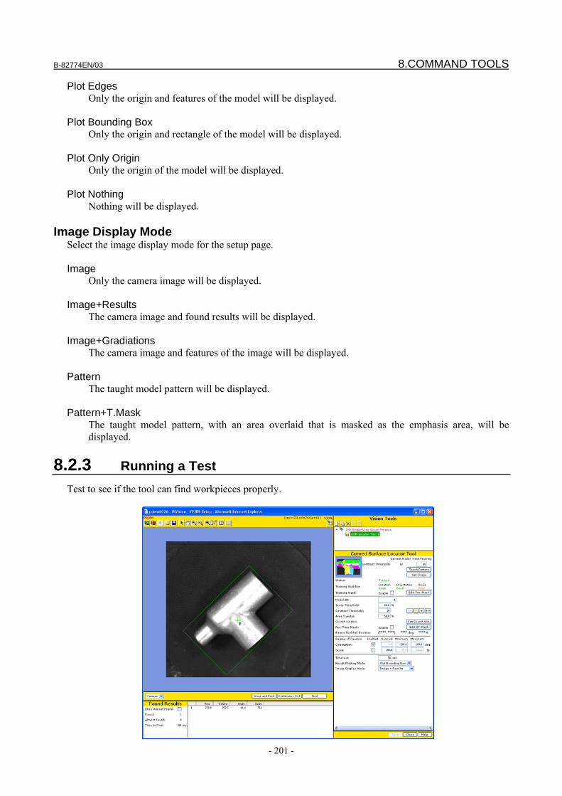
B-82774EN/03 8.COMMAND TOOLS
- 201 -
Plot Edges Only the origin and features of the model will be displayed.
Plot Bounding Box
Only the origin and rectangle of the model will be displayed. Plot Only Origin
Only the origin of the model will be displayed. Plot Nothing
Nothing will be displayed.
Image Display Mode Select the image display mode for the setup page. Image
Only the camera image will be displayed. Image+Results
The camera image and found results will be displayed. Image+Gradiations
The camera image and features of the image will be displayed. Pattern
The taught model pattern will be displayed. Pattern+T.Mask
The taught model pattern, with an area overlaid that is masked as the emphasis area, will be displayed.
8.2.3 Running a Test Test to see if the tool can find workpieces properly.
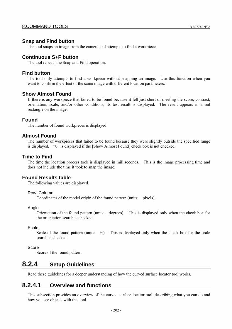
8.COMMAND TOOLS B-82774EN/03
- 202 -
Snap and Find button
The tool snaps an image from the camera and attempts to find a workpiece.
Continuous S+F button The tool repeats the Snap and Find operation.
Find button The tool only attempts to find a workpiece without snapping an image. Use this function when you want to confirm the effect of the same image with different location parameters.
Show Almost Found If there is any workpiece that failed to be found because it fell just short of meeting the score, contrast, orientation, scale, and/or other conditions, its test result is displayed. The result appears in a red rectangle on the image.
Found The number of found workpieces is displayed.
Almost Found The number of workpieces that failed to be found because they were slightly outside the specified range is displayed. “0” is displayed if the [Show Almost Found] check box is not checked.
Time to Find The time the location process took is displayed in milliseconds. This is the image processing time and does not include the time it took to snap the image.
Found Results table The following values are displayed. Row, Column
Coordinates of the model origin of the found pattern (units: pixels). Angle
Orientation of the found pattern (units: degrees). This is displayed only when the check box for the orientation search is checked.
Scale
Scale of the found pattern (units: %). This is displayed only when the check box for the scale search is checked.
Score
Score of the found pattern.
8.2.4 Setup Guidelines Read these guidelines for a deeper understanding of how the curved surface locator tool works.
8.2.4.1 Overview and functions This subsection provides an overview of the curved surface locator tool, describing what you can do and how you see objects with this tool.
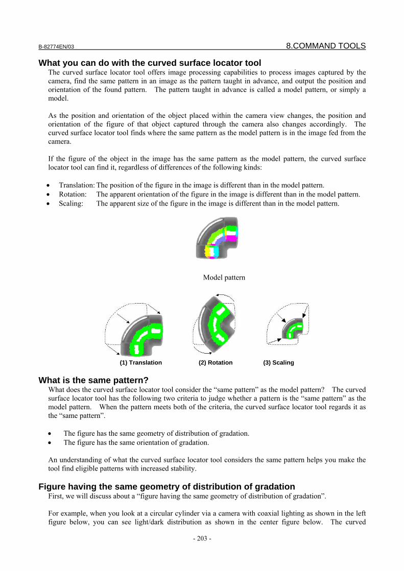
B-82774EN/03 8.COMMAND TOOLS
- 203 -
What you can do with the curved surface locator tool The curved surface locator tool offers image processing capabilities to process images captured by the camera, find the same pattern in an image as the pattern taught in advance, and output the position and orientation of the found pattern. The pattern taught in advance is called a model pattern, or simply a model. As the position and orientation of the object placed within the camera view changes, the position and orientation of the figure of that object captured through the camera also changes accordingly. The curved surface locator tool finds where the same pattern as the model pattern is in the image fed from the camera. If the figure of the object in the image has the same pattern as the model pattern, the curved surface locator tool can find it, regardless of differences of the following kinds: • Translation: The position of the figure in the image is different than in the model pattern. • Rotation: The apparent orientation of the figure in the image is different than in the model pattern. • Scaling: The apparent size of the figure in the image is different than in the model pattern.
Model pattern
(1) Translation (2) Rotation (3) Scaling
What is the same pattern?
What does the curved surface locator tool consider the “same pattern” as the model pattern? The curved surface locator tool has the following two criteria to judge whether a pattern is the “same pattern” as the model pattern. When the pattern meets both of the criteria, the curved surface locator tool regards it as the “same pattern”. • The figure has the same geometry of distribution of gradation. • The figure has the same orientation of gradation. An understanding of what the curved surface locator tool considers the same pattern helps you make the tool find eligible patterns with increased stability.
Figure having the same geometry of distribution of gradation First, we will discuss about a “figure having the same geometry of distribution of gradation”. For example, when you look at a circular cylinder via a camera with coaxial lighting as shown in the left figure below, you can see light/dark distribution as shown in the center figure below. The curved
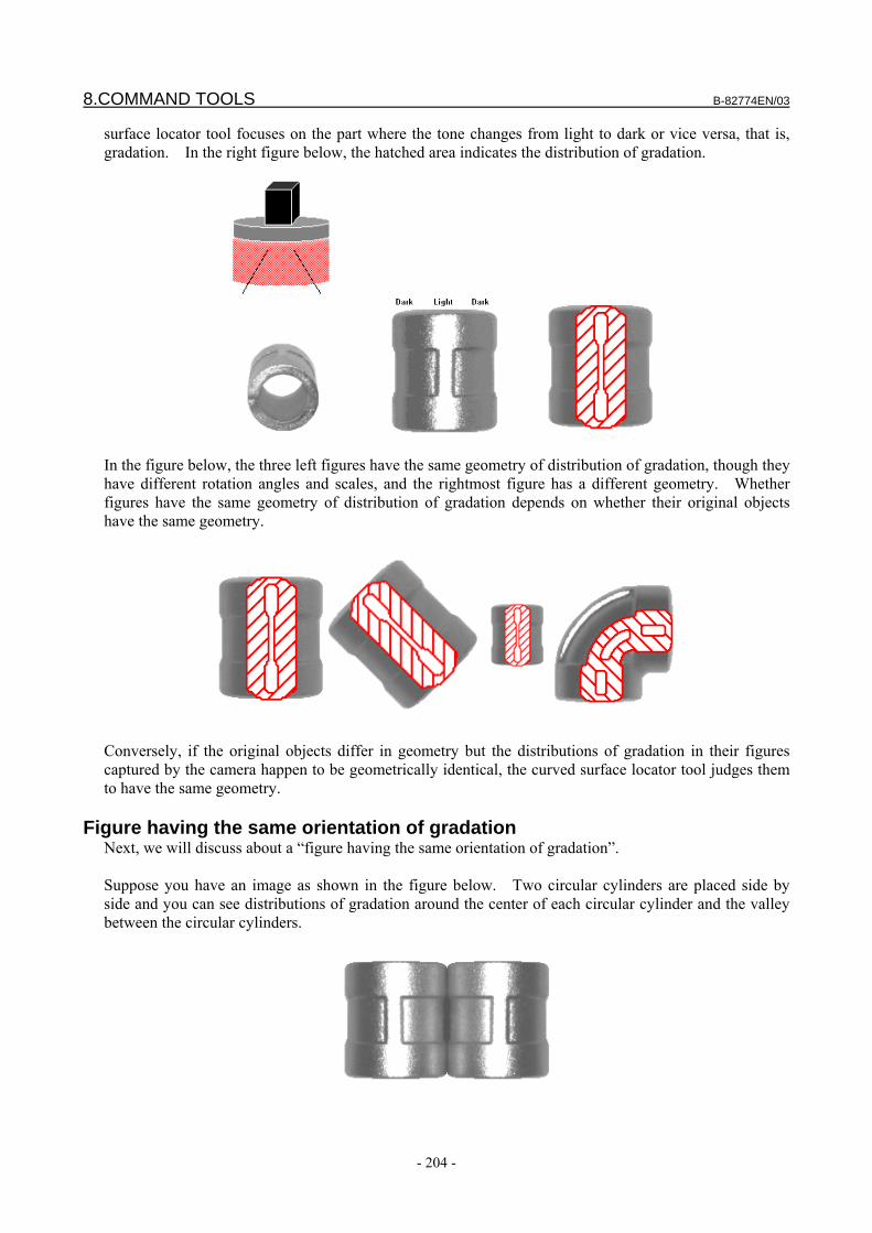
8.COMMAND TOOLS B-82774EN/03
- 204 -
surface locator tool focuses on the part where the tone changes from light to dark or vice versa, that is, gradation. In the right figure below, the hatched area indicates the distribution of gradation.
In the figure below, the three left figures have the same geometry of distribution of gradation, though they have different rotation angles and scales, and the rightmost figure has a different geometry. Whether figures have the same geometry of distribution of gradation depends on whether their original objects have the same geometry.
Conversely, if the original objects differ in geometry but the distributions of gradation in their figures captured by the camera happen to be geometrically identical, the curved surface locator tool judges them to have the same geometry.
Figure having the same orientation of gradation Next, we will discuss about a “figure having the same orientation of gradation”. Suppose you have an image as shown in the figure below. Two circular cylinders are placed side by side and you can see distributions of gradation around the center of each circular cylinder and the valley between the circular cylinders.
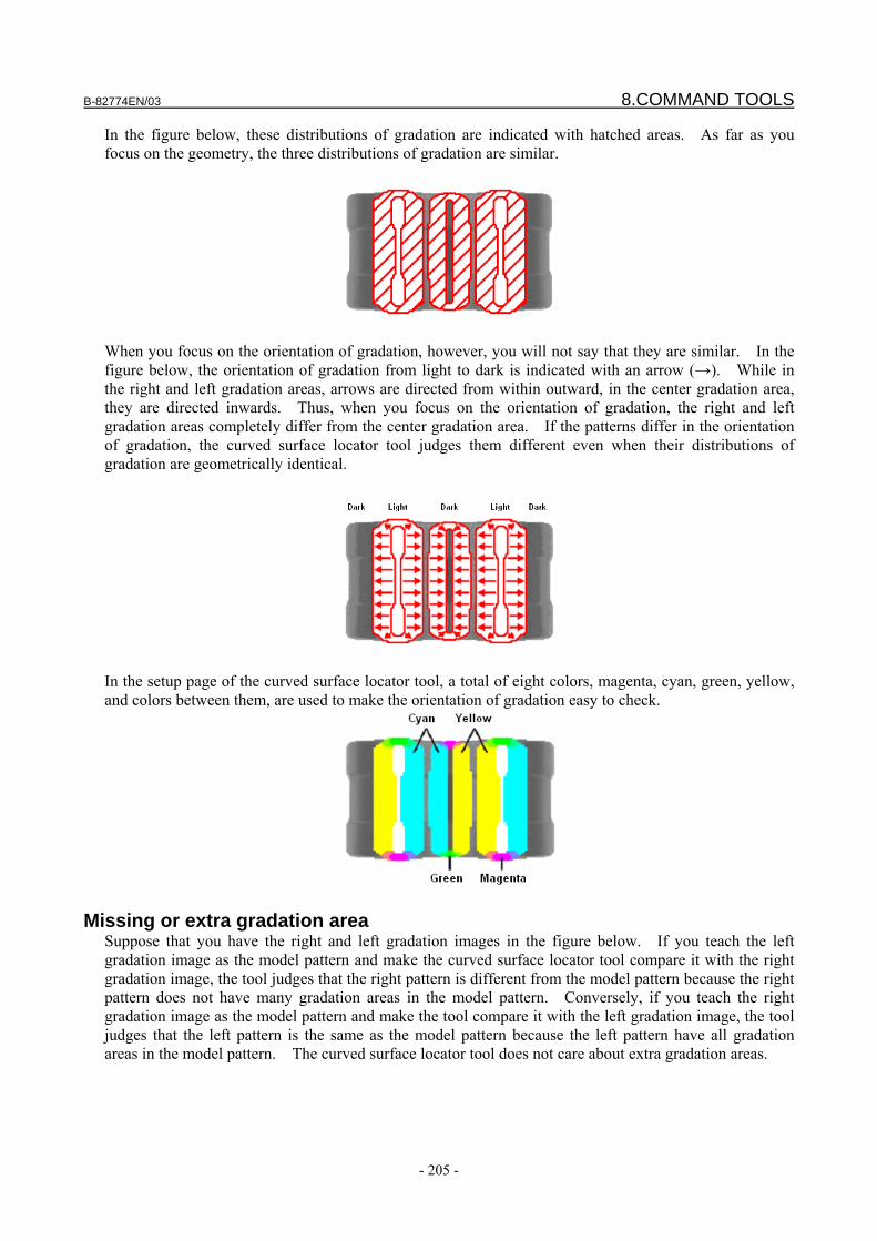
B-82774EN/03 8.COMMAND TOOLS
- 205 -
In the figure below, these distributions of gradation are indicated with hatched areas. As far as you focus on the geometry, the three distributions of gradation are similar.
When you focus on the orientation of gradation, however, you will not say that they are similar. In the figure below, the orientation of gradation from light to dark is indicated with an arrow (→). While in the right and left gradation areas, arrows are directed from within outward, in the center gradation area, they are directed inwards. Thus, when you focus on the orientation of gradation, the right and left gradation areas completely differ from the center gradation area. If the patterns differ in the orientation of gradation, the curved surface locator tool judges them different even when their distributions of gradation are geometrically identical.
In the setup page of the curved surface locator tool, a total of eight colors, magenta, cyan, green, yellow, and colors between them, are used to make the orientation of gradation easy to check.
Missing or extra gradation area Suppose that you have the right and left gradation images in the figure below. If you teach the left gradation image as the model pattern and make the curved surface locator tool compare it with the right gradation image, the tool judges that the right pattern is different from the model pattern because the right pattern does not have many gradation areas in the model pattern. Conversely, if you teach the right gradation image as the model pattern and make the tool compare it with the left gradation image, the tool judges that the left pattern is the same as the model pattern because the left pattern have all gradation areas in the model pattern. The curved surface locator tool does not care about extra gradation areas.
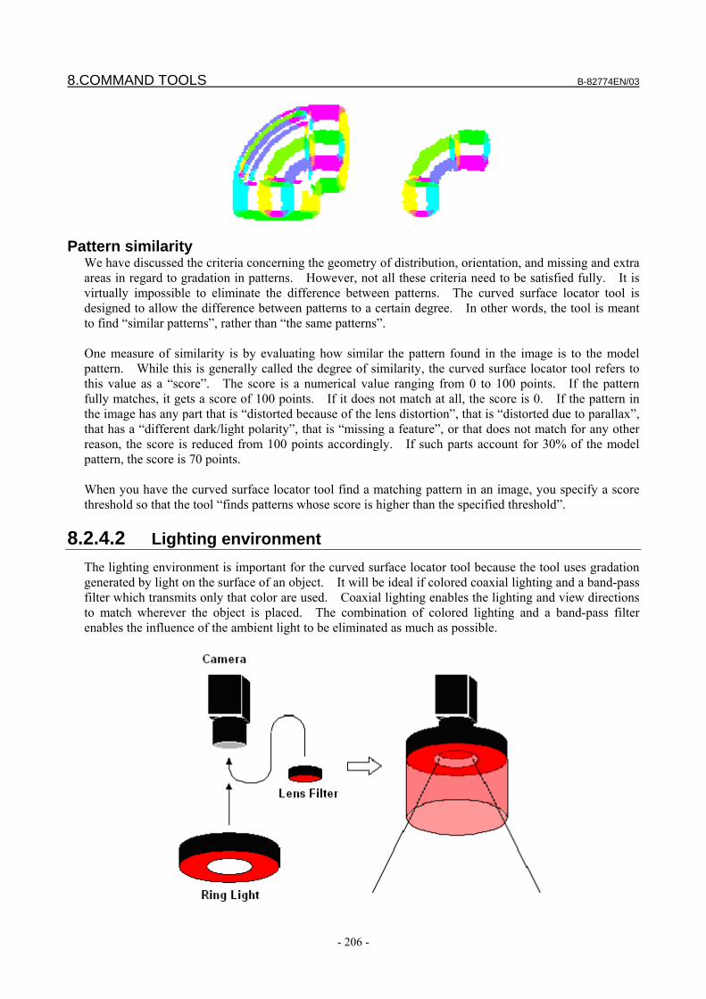
8.COMMAND TOOLS B-82774EN/03
- 206 -
Pattern similarity We have discussed the criteria concerning the geometry of distribution, orientation, and missing and extra areas in regard to gradation in patterns. However, not all these criteria need to be satisfied fully. It is virtually impossible to eliminate the difference between patterns. The curved surface locator tool is designed to allow the difference between patterns to a certain degree. In other words, the tool is meant to find “similar patterns”, rather than “the same patterns”. One measure of similarity is by evaluating how similar the pattern found in the image is to the model pattern. While this is generally called the degree of similarity, the curved surface locator tool refers to this value as a “score”. The score is a numerical value ranging from 0 to 100 points. If the pattern fully matches, it gets a score of 100 points. If it does not match at all, the score is 0. If the pattern in the image has any part that is “distorted because of the lens distortion”, that is “distorted due to parallax”, that has a “different dark/light polarity”, that is “missing a feature”, or that does not match for any other reason, the score is reduced from 100 points accordingly. If such parts account for 30% of the model pattern, the score is 70 points. When you have the curved surface locator tool find a matching pattern in an image, you specify a score threshold so that the tool “finds patterns whose score is higher than the specified threshold”.
8.2.4.2 Lighting environment The lighting environment is important for the curved surface locator tool because the tool uses gradation generated by light on the surface of an object. It will be ideal if colored coaxial lighting and a band-pass filter which transmits only that color are used. Coaxial lighting enables the lighting and view directions to match wherever the object is placed. The combination of colored lighting and a band-pass filter enables the influence of the ambient light to be eliminated as much as possible.
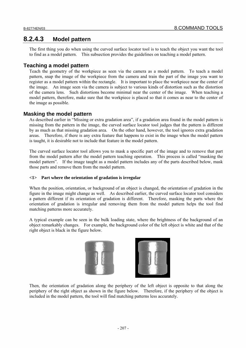
B-82774EN/03 8.COMMAND TOOLS
- 207 -
8.2.4.3 Model pattern The first thing you do when using the curved surface locator tool is to teach the object you want the tool to find as a model pattern. This subsection provides the guidelines on teaching a model pattern.
Teaching a model pattern Teach the geometry of the workpiece as seen via the camera as a model pattern. To teach a model pattern, snap the image of the workpiece from the camera and train the part of the image you want to register as a model pattern within the rectangle. It is important to place the workpiece near the center of the image. An image seen via the camera is subject to various kinds of distortion such as the distortion of the camera lens. Such distortions become minimal near the center of the image. When teaching a model pattern, therefore, make sure that the workpiece is placed so that it comes as near to the center of the image as possible.
Masking the model pattern As described earlier in “Missing or extra gradation area”, if a gradation area found in the model pattern is missing from the pattern in the image, the curved surface locator tool judges that the pattern is different by as much as that missing gradation area. On the other hand, however, the tool ignores extra gradation areas. Therefore, if there is any extra feature that happens to exist in the image when the model pattern is taught, it is desirable not to include that feature in the model pattern. The curved surface locator tool allows you to mask a specific part of the image and to remove that part from the model pattern after the model pattern teaching operation. This process is called “masking the model pattern”. If the image taught as a model pattern includes any of the parts described below, mask those parts and remove them from the model pattern. <1> Part where the orientation of gradation is irregular When the position, orientation, or background of an object is changed, the orientation of gradation in the figure in the image might change as well. As described earlier, the curved surface locator tool considers a pattern different if its orientation of gradation is different. Therefore, masking the parts where the orientation of gradation is irregular and removing them from the model pattern helps the tool find matching patterns more accurately. A typical example can be seen in the bulk loading state, where the brightness of the background of an object remarkably changes. For example, the background color of the left object is white and that of the right object is black in the figure below.
Then, the orientation of gradation along the periphery of the left object is opposite to that along the periphery of the right object as shown in the figure below. Therefore, if the periphery of the object is included in the model pattern, the tool will find matching patterns less accurately.
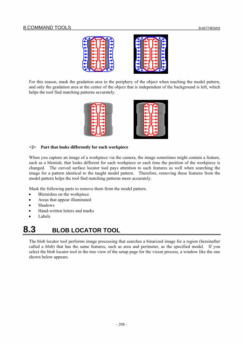
8.COMMAND TOOLS B-82774EN/03
- 208 -
For this reason, mask the gradation area in the periphery of the object when teaching the model pattern, and only the gradation area at the center of the object that is independent of the background is left, which helps the tool find matching patterns accurately.
<2> Part that looks differently for each workpiece When you capture an image of a workpiece via the camera, the image sometimes might contain a feature, such as a blemish, that looks different for each workpiece or each time the position of the workpiece is changed. The curved surface locator tool pays attention to such features as well when searching the image for a pattern identical to the taught model pattern. Therefore, removing these features from the model pattern helps the tool find matching patterns more accurately. Mask the following parts to remove them from the model pattern. • Blemishes on the workpiece • Areas that appear illuminated • Shadows • Hand-written letters and marks • Labels
8.3 BLOB LOCATOR TOOL The blob locator tool performs image processing that searches a binarized image for a region (hereinafter called a blob) that has the same features, such as area and perimeter, as the specified model. If you select the blob locator tool in the tree view of the setup page for the vision process, a window like the one shown below appears.
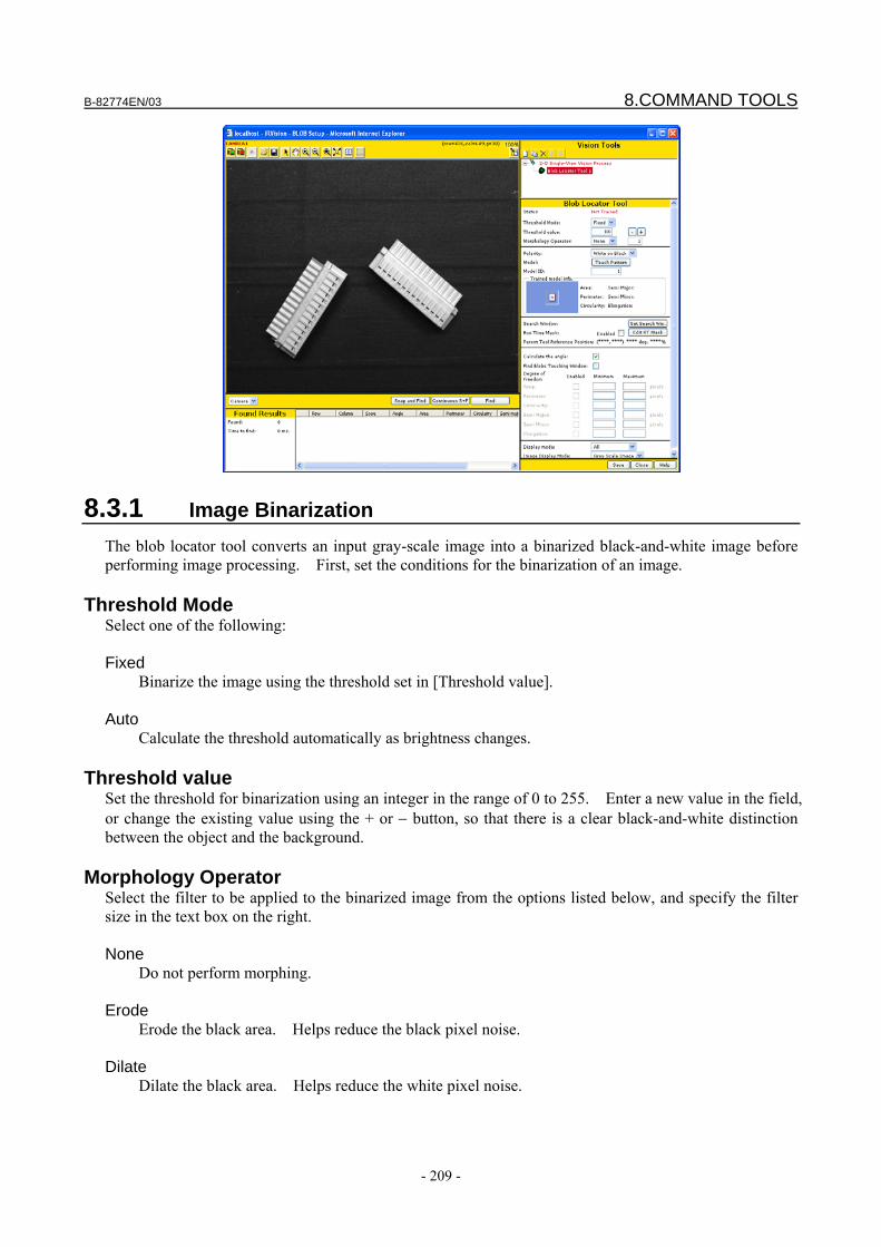
B-82774EN/03 8.COMMAND TOOLS
- 209 -
8.3.1 Image Binarization The blob locator tool converts an input gray-scale image into a binarized black-and-white image before performing image processing. First, set the conditions for the binarization of an image.
Threshold Mode Select one of the following: Fixed
Binarize the image using the threshold set in [Threshold value]. Auto
Calculate the threshold automatically as brightness changes.
Threshold value Set the threshold for binarization using an integer in the range of 0 to 255. Enter a new value in the field, or change the existing value using the + or − button, so that there is a clear black-and-white distinction between the object and the background.
Morphology Operator Select the filter to be applied to the binarized image from the options listed below, and specify the filter size in the text box on the right. None
Do not perform morphing. Erode
Erode the black area. Helps reduce the black pixel noise. Dilate
Dilate the black area. Helps reduce the white pixel noise.
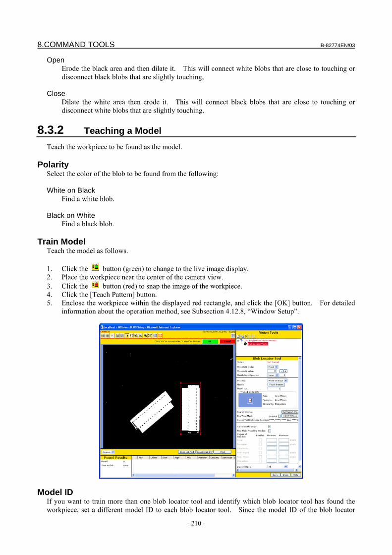
8.COMMAND TOOLS B-82774EN/03
- 210 -
Open Erode the black area and then dilate it. This will connect white blobs that are close to touching or disconnect black blobs that are slightly touching,
Close Dilate the white area then erode it. This will connect black blobs that are close to touching or
disconnect white blobs that are slightly touching.
8.3.2 Teaching a Model Teach the workpiece to be found as the model.
Polarity Select the color of the blob to be found from the following: White on Black Find a white blob. Black on White Find a black blob.
Train Model Teach the model as follows. 1. Click the button (green) to change to the live image display. 2. Place the workpiece near the center of the camera view. 3. Click the button (red) to snap the image of the workpiece. 4. Click the [Teach Pattern] button. 5. Enclose the workpiece within the displayed red rectangle, and click the [OK] button. For detailed
information about the operation method, see Subsection 4.12.8, “Window Setup”.
Model ID If you want to train more than one blob locator tool and identify which blob locator tool has found the workpiece, set a different model ID to each blob locator tool. Since the model ID of the blob locator
B-82774EN/03 8.COMMAND TOOLS
- 211 -
tool that has found the workpiece is sent to a vision register along with the offset data, the robot program can identify the model ID of the found workpiece.
Trained model info. The feature information of the trained model is displayed. Together with the image enclosed by a rectangle when training the model, the feature information of the trained blob is displayed.
8.3.3 Adjusting the Location Parameters Adjust the location parameters.
Search Window Specify the range of the area of the image to be searched. The narrower the range is, the faster the location process ends. The default value is the entire image. To change the search window, click the [Set Search Win.] button. When a rectangle appears on the image, adjust its geometry, as when teaching a model. For detailed information about the operation method, see Subsection 4.12.8, “Window Setup”.
Runtime Mask Specify an area of the search window that you do not want processed, as an arbitrary geometry. Use this function when you want to specify a search window of an arbitrary geometry, such as a circle- or donut-shaped window. The filled area will be masked in the rectangle specified as the search window and will not be subject to the image processing. To change the run-time mask, click the [Edit RT Mask] button. For detailed information about the operation method, see Subsection 4.12.9, “Editing Masks”.
Calculate the angle Specify whether to calculate the orientation of the found blob. If you check this box, the orientation of the blob will be calculated. The blob locator tool can recognize orientation in the range from −90 to +90 degrees. If you uncheck this box, the long axis length, short axis length, and elongation of the found blob will not be calculated.
Find Blobs Touching Window The blob locator tool outputs the center of mass of the blob as the found location. If the blob is in contact with the search window, it is impossible to know how much of the blob extends out of the search window, in which case the center of mass cannot be calculated accurately. By default, therefore, the blob locator tool ignores any blob touching the search window. However, checking this box causes the tool to find blobs touching the search window as well. Use this function when you want to measure the area of the black region in the image, rather than finding the location of a blob.
CAUTION Uncheck this box if you want to find the location of a workpiece using the blob
locator tool. By default, the box is not checked.
DOF – Area Specify the range of area values for judging the blob to match the model. If the area of the found blob is within the range specified by [minimum] and [Maximum], the location succeeds. If you uncheck the box, the area will not be checked.

8.COMMAND TOOLS B-82774EN/03
- 212 -
DOF – Perimeter Specify the range of perimeter values for judging the blob to match the model. If the perimeter of the found blob is within the range specified by [Minimum] and [Maximum], the location succeeds. If you uncheck the box, the perimeter will not be checked.
DOF – Circularity The degree of circularity is calculated by dividing the 4π area by square of perimeter and represents how closely the found blob resembles a circle. If the blob is a perfect circle, this value is 1.0. The more complex the blob becomes in geometry, the smaller the value becomes. Specify the range of degrees of circularity for judging the blob to match the model. If the degree of circularity of the found blob is within the range specified by [Minimum] and [Maximum], the location succeeds. If you uncheck the box, the degree of circularity will not be checked.
DOF – Semi Major Specify the range of semi-major axis length values for judging the blob to match the model. If the semi-major axis length of the found blob is within the range specified by [Minimum] and [Maximum], the location succeeds. If you uncheck the box, the semi-major axis length will not be checked.
DOF – Semi Minor Specify the range of semi-minor axis length values for judging the blob to match the model. If the semi-minor axis length of the found blob is within the range specified by [Minimum] and [Maximum], the location succeeds. If you uncheck the box, the semi-minor axis length will not be checked.
DOF – Elongation Elongation is calculated by dividing the semi-major axis length by the semi-minor axis length and represents how slender the found blob is. The longer the blob is, the larger the value becomes. Specify the range of elongation values for judging the blob to match the model. If the elongation of the found blob is within the range specified by [Minimum] and [Maximum], the location succeeds. If you uncheck the box, the elongation will not be checked.
Display Mode Select how the found result is to be displayed on the image after the process is run. Found Position
Only the center of mass of the blob will be displayed. Contour
Only the contour of the blob will be displayed. All
Both the center of mass and contour of the blob will be displayed.
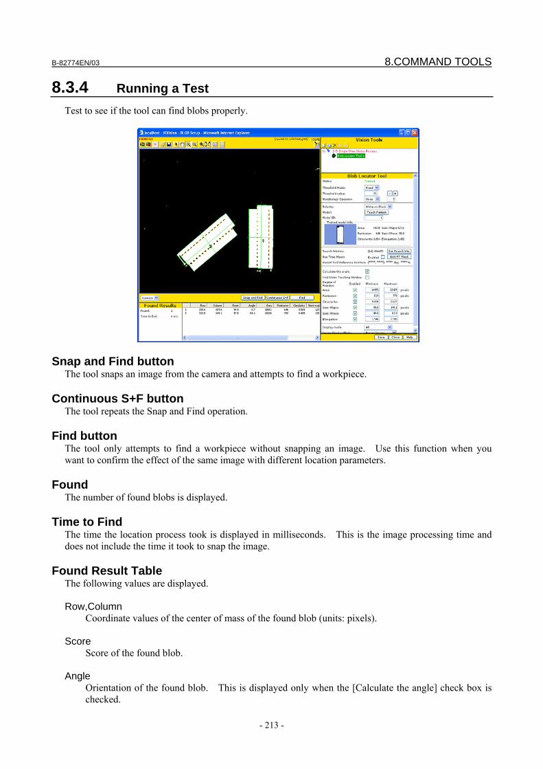
B-82774EN/03 8.COMMAND TOOLS
- 213 -
8.3.4 Running a Test Test to see if the tool can find blobs properly.
Snap and Find button The tool snaps an image from the camera and attempts to find a workpiece.
Continuous S+F button The tool repeats the Snap and Find operation.
Find button The tool only attempts to find a workpiece without snapping an image. Use this function when you want to confirm the effect of the same image with different location parameters.
Found The number of found blobs is displayed.
Time to Find The time the location process took is displayed in milliseconds. This is the image processing time and does not include the time it took to snap the image.
Found Result Table The following values are displayed. Row,Column
Coordinate values of the center of mass of the found blob (units: pixels). Score
Score of the found blob. Angle
Orientation of the found blob. This is displayed only when the [Calculate the angle] check box is checked.
8.COMMAND TOOLS B-82774EN/03
- 214 -
Area Area of the found blob (units: pixels).
Perimeter
Perimeter of the found blob (units: pixels). Circularity
Degree of circularity of the found blob. Semi-major
Long axis length of the found blob (units: pixels). Semi-minor
Short axis length of the found blob (units: pixels). Elongation
Elongation of the found blob.
NOTE If the tool fails to find the object you want found, run the find test with all the
search range boxes unchecked, in order to identify which item causes the location to fail. With the DOF parameters unchecked, all the blobs in the image are found. This allows you to examine which of the parameters of the specific blob are outside the originally specified range, preventing the blob you want found from being detected with the original settings. After that, set an appropriate range for that item.
Image Display Mode
Select the image display mode for the setup page. Grayscale Image
The camera image will be displayed as is. Binary Image
The camera image will be binarized when displayed.
B-82774EN/03 8.COMMAND TOOLS
- 215 -
8.4 EDGE PAIR LOCATOR TOOL The edge pair locator tool finds two parallel lines (edge pair) that are the same as the trained model pattern from an image and outputs the center position of the edge pair and the distance between the edges. It is mainly used for length measurement. If you select the edge pair locator tool in the tree view of the setup page for the vision process, a page like the one shown below appears.
8.4.1 Setting the Search Window Set the area to be searched for an edge pair.
Search Area Specify the range of the area of the image to be measured. The shorter the measurement area is in height, the more accurately the position of the edges is found. To change the measurement area, click the [Set Search Area] button. When a red rectangle appears on the image, enclose the area containing the edge pair to find with the displayed rectangle, and click the [OK] button. For detailed information about the operation method, see Subsection 4.12.8, "Window Setup".
Parent Tool Reference Position It is the reference position to be used for dynamic window shifting. This section displays the position of the workpiece found by the parent locator tool when the search area is taught.
8.4.2 Teaching a Model Teach the edge pair to be found as the model. The procedure for teaching the model is as follows. 1. Click the [Train Model] button. 2. The edge found in the measurement area is displayed in the window. First, drag the red marker to
the left edge of the edge pair used as the model, and then click the [OK] button. 3. The selected edge is highlighted by a blue line. Next, drag the red marker to the right edge of the
edge pair used as the model, and then click the [OK] button. When the model teaching process is completed, the information on the taught model is displayed.

8.COMMAND TOOLS B-82774EN/03
- 216 -
Model Image The edge pair to be found and the distance between the paired edges are displayed. The polarity of the edges to be found (from white to black or black to white) can be seen.
Standard Length It is the distance between edges of the model edge pair. At runtime, if two or more edge pair candidates are found in the search window and they overlap each other, priority is given to the edge pair whose distance between edges is closest to the standard length.
Left/Right Edge Contrast It is the contrast of edges of the model edge pair. At runtime, if two or more edge pair candidates are found in the search window and they overlap each other, priority is given to the edge pair whose contrast is closest to that of the model edge pair.
8.4.3 Adjusting the Location Parameters Adjust the location parameters.
Contrast Threshold Specify the contrast threshold for the search. The default value is 30. If you set a small value, the tool will be able to find the edges with less contrast but it will take longer to complete the location process. The minimum value is 1. If the contrast is set too low false edges may be found, if this is the case raise contrast threshold. The edges whose contrast is lower than the threshold are ignored.
Maximum Length to Search Specify the maximum inter-edge distance of the edge pair to be found. When a model edge pair is taught, a value that is 105% of the standard length is input as the default value.
Minimum Length to Search Specify the minimum inter-edge distance of the edge pair to be found. When a model edge pair is taught, a value that is 95% of the standard length is input as the default value.
B-82774EN/03 8.COMMAND TOOLS
- 217 -
8.4.4 Running a Test Test to see if the tool can find workpieces properly.
Display Mode Select the image display mode for the Setup Page. Edge The search area, the measured edge pair distance (green arrow), and the center position of the found
edge pair are displayed. Edges + Arrow The scan direction (blue arrow), the measured edge pair distance (green arrow), and the center
position of the found edge pair are displayed. Edges + Proj. + Grad. In addition to the information presented in the Edge mode, graphs are displayed that show changes
in contrast and gradient of the search area. Edges + Proj. + Grad.+ Arrow In addition to the information presented in the Edges + Arrow mode, graphs are displayed that show
changes in contrast and gradient of the search area.
Result Show Mode Select the mode for displaying the result on the setup window. Found Results Of the found edge pairs, the one to be output as the found result is displayed. All Edge Pairs All the edge pairs whose polarity (from white to black or black to white) matches that of the model
edge pair are displayed, irrespective of the length.
Snap and Find button The tool snaps an image from the camera and attempts to find a workpiece.
8.COMMAND TOOLS B-82774EN/03
- 218 -
Continuous S+F button The tool repeats the Snap and Find operation.
Find button The tool only attempts to find a workpiece without snapping an image. Use this function when you want to confirm the effect of the same image with different location parameters.
Time to Find The time the location process took is displayed in milliseconds. This only represents the time it took to process the image and does not include the time it took to snap it.
Result to Display If the edge pair locator tool is inserted as a child tool of a locator tool, and if the parent locator tool outputs multiple found results, you can display the result corresponding to a specific found result of the parent tool by selecting a result number. Selecting [All] displays the results for all the found results of the parent locator tool.
Found result table - Found Results For the edge pair locator tool, the items displayed in the found result table differ depending on the item selected in [Result Show Mode]. When [Found Results] is selected, the found edge pair to be output as the found result is displayed. Vt, Hz Coordinates of the center of mass of the found edge pair (unit: pixel). Angle Rotation angle of the measurement area at the time when the location process is executed, relative to
the measurement area at the time of setup. Length Inter-edge distance of the found edge pair (unit: pixel). Contrast Average contract of the found edge pair. Edge 1 Vt Vertical-direction coordinate of the left edge of the found edge pair (unit: pixel). Edge 1 Hz Horizontal-direction coordinate of the left edge of the found edge pair (unit: pixel). Edge 2 Vt Vertical-direction coordinate of the right edge of the found edge pair (unit: pixel). Edge 2 Hz Horizontal-direction coordinate of the right edge of the found edge pair (unit: pixel).
Found result table - All Edge Pairs If you select [All Edge Pairs], all the edge pairs whose polarity (from white to black or black to white) matches that of the model are displayed, irrespective of the length. Length Distance between found edge pairs (unit: pixel).
B-82774EN/03 8.COMMAND TOOLS
- 219 -
Contrast 1 Average contrast of the left edge of the found edge pair. Contrast 2 Average contrast of the right edge of the found edge pair.
8.5 HISTOGRAM TOOL The histogram tool measures the brightness of an image. When the histogram tool is located below a locator tool, such as the GPM Locator Tool, in the tree view, the measurement window of the histogram tool moves dynamically according to the found result of the parent locator tool. If you select the histogram tool in the tree view of the setup page for the vision process, a window like the one shown below appears.
8.5.1 Setting the Measurement Area Set the area whose brightness is to be measured, as follows. 1. Click the button (green) to change to the live image display. 2. Place the workpiece near the center of the camera view. 3. Click the button (red) to snap the image of the workpiece. 4. Click the [Set] button for [Area to measure brightness]. The parent locator tool runs automatically, and a red + mark appears on the found object. If the location fails, an alarm message to that effect is displayed and the measurement area setting is stopped. 5. Select the area to measure, using the displayed red rectangle, and click the [OK] button. For
detailed information about the operation method, see Subsection 4.12.8, “Window Setup”.
8.COMMAND TOOLS B-82774EN/03
- 220 -
The values shown in [Reference Position] indicate the position of the object that the parent locator tool found when the measurement area was specified.
Run-Time Mask Specify an area of the measurement window that you do not want processed as an arbitrary geometry. The filled area will be masked in the rectangle specified as the measurement window and will not be subject to the image processing. To change the run-time mask, click the [Edit RT Mask] button. For detailed information about the operation method, see Subsection 4.12.9, “Editing Masks”.
Filter Type Before measuring a histogram, you can apply a filter to the image. None Do not use a filter. Blur Apply a filter to blur the image. Blurring an image obscures brightness differences in the image,
thus helping alleviate the effect of noise.
Times Specify the number of times the filter is to be applied. Currently, this item is available only when [Blur] is set in [Filter Type]. The larger the number, the stronger the blurring effect. The specifiable value range is 1 to 10.
Range of Interest Specify the brightness range of interest from 0 (dark) to 255 (bright). [Within Range (%)], described later, indicates the percentage of pixels within the specified brightness range.
Image Display Mode Select the type of image to be displayed in the image display frame from the following two types: Original Image Display the image as it is captured by the camera. Filtered Image
B-82774EN/03 8.COMMAND TOOLS
- 221 -
Display the image resulting from applying a specified filter to the original image.
8.5.2 Running a Test Run a measurement test to see if the tool can find brightness properly.
Snap and Find button The tool snaps an image from the camera and attempts to perform the measurement.
Continuous S+F button The tool repeats the Snap and Find operation.
Find button The tool only performs the measurement without snapping an image from the camera.
Time to Find The time the histogram measurement took is displayed in milliseconds.
Measurement Result Table
The following values are displayed. Num. Pixels
Total number of pixels in the measured area. Maximum
Brightness of the brightest pixel in the measured area. Minimum
Brightness of the darkest pixel in the measured area. Median
Median of the brightness of the measured area.
8.COMMAND TOOLS B-82774EN/03
- 222 -
Mode Most common brightness of pixels in the measured area.
Mean
Mean brightness of the measured area. Std. Dev.
Standard deviation in brightness of the measured area. Within Range (%) Ratio of the number of pixels within the brightness range specified in [Range of Interest] to the total
number of pixels in the area whose brightness has been measured. Out of Range (%) Ratio of the number of pixels outside the brightness range specified in [Range of Interest] to the total
number of pixels in the area whose brightness has been measured.
8.6 EDGE HISTOGRAM TOOL The edge histogram tool measures the changes (gradients) in brightness of an image. When the edge histogram tool is located below a locator tool, such as the GPM locator tool, in the tree view, the measurement window of the edge histogram tool shifts according to the found result of the parent locator tool. If you select the edge histogram tool in the tree view of the setup page for the vision process, a window like the one shown below appears.
8.6.1 Setting the Measurement Area Set the area whose gradients are to be measured, as follows. 1. Click the button (green) to change to the live image display. 2. Place the workpiece near the center of the camera view. 3. Click the button (red) to snap the image of the workpiece. 4. Click the [Set] button for [Measurement area].
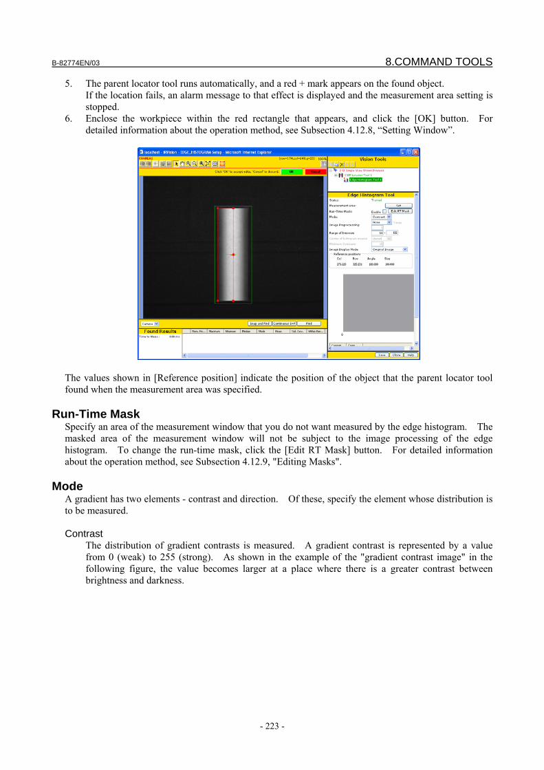
B-82774EN/03 8.COMMAND TOOLS
- 223 -
5. The parent locator tool runs automatically, and a red + mark appears on the found object. If the location fails, an alarm message to that effect is displayed and the measurement area setting is stopped.
6. Enclose the workpiece within the red rectangle that appears, and click the [OK] button. For detailed information about the operation method, see Subsection 4.12.8, “Setting Window”.
The values shown in [Reference position] indicate the position of the object that the parent locator tool found when the measurement area was specified.
Run-Time Mask Specify an area of the measurement window that you do not want measured by the edge histogram. The masked area of the measurement window will not be subject to the image processing of the edge histogram. To change the run-time mask, click the [Edit RT Mask] button. For detailed information about the operation method, see Subsection 4.12.9, "Editing Masks".
Mode A gradient has two elements - contrast and direction. Of these, specify the element whose distribution is to be measured. Contrast The distribution of gradient contrasts is measured. A gradient contrast is represented by a value
from 0 (weak) to 255 (strong). As shown in the example of the "gradient contrast image" in the following figure, the value becomes larger at a place where there is a greater contrast between brightness and darkness.
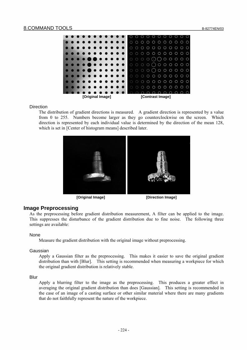
8.COMMAND TOOLS B-82774EN/03
- 224 -
[Original Image] [Contrast Image]
Direction The distribution of gradient directions is measured. A gradient direction is represented by a value
from 0 to 255. Numbers become larger as they go counterclockwise on the screen. Which direction is represented by each individual value is determined by the direction of the mean 128, which is set in [Center of histogram means] described later.
[Original Image] [Direction Image]
Image Preprocessing
As the preprocessing before gradient distribution measurement, A filter can be applied to the image. This suppresses the disturbance of the gradient distribution due to fine noise. The following three settings are available: None Measure the gradient distribution with the original image without preprocessing. Gaussian Apply a Gaussian filter as the preprocessing. This makes it easier to save the original gradient
distribution than with [Blur]. This setting is recommended when measuring a workpiece for which the original gradient distribution is relatively stable.
Blur Apply a blurring filter to the image as the preprocessing. This produces a greater effect in
averaging the original gradient distribution than does [Gaussian]. This setting is recommended in the case of an image of a casting surface or other similar material where there are many gradients that do not faithfully represent the nature of the workpiece.
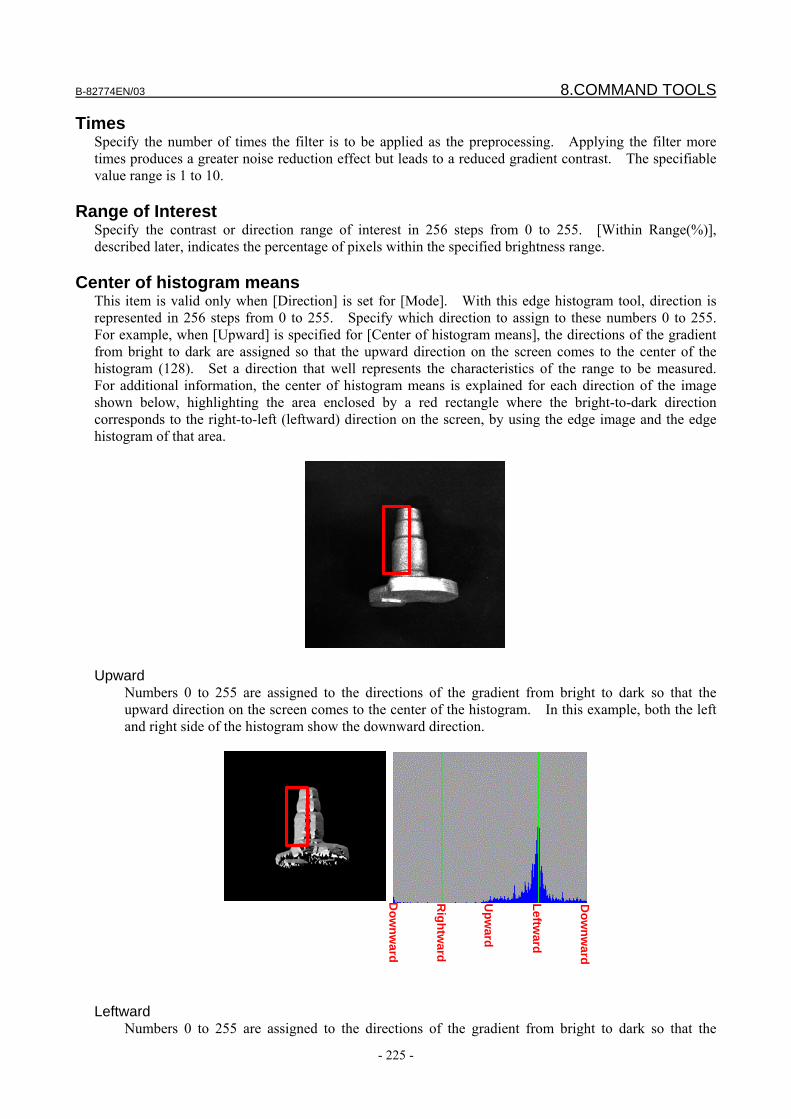
B-82774EN/03 8.COMMAND TOOLS
- 225 -
Times Specify the number of times the filter is to be applied as the preprocessing. Applying the filter more times produces a greater noise reduction effect but leads to a reduced gradient contrast. The specifiable value range is 1 to 10.
Range of Interest Specify the contrast or direction range of interest in 256 steps from 0 to 255. [Within Range(%)], described later, indicates the percentage of pixels within the specified brightness range.
Center of histogram means This item is valid only when [Direction] is set for [Mode]. With this edge histogram tool, direction is represented in 256 steps from 0 to 255. Specify which direction to assign to these numbers 0 to 255. For example, when [Upward] is specified for [Center of histogram means], the directions of the gradient from bright to dark are assigned so that the upward direction on the screen comes to the center of the histogram (128). Set a direction that well represents the characteristics of the range to be measured. For additional information, the center of histogram means is explained for each direction of the image shown below, highlighting the area enclosed by a red rectangle where the bright-to-dark direction corresponds to the right-to-left (leftward) direction on the screen, by using the edge image and the edge histogram of that area.
Upward
Numbers 0 to 255 are assigned to the directions of the gradient from bright to dark so that the upward direction on the screen comes to the center of the histogram. In this example, both the left and right side of the histogram show the downward direction.
Leftward
Numbers 0 to 255 are assigned to the directions of the gradient from bright to dark so that the
Dow
nward
Rightw
ard
Upw
ard
Dow
nward
Leftward
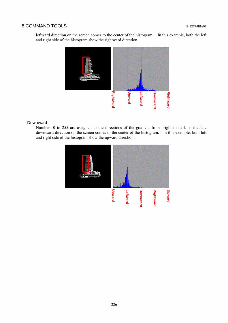
8.COMMAND TOOLS B-82774EN/03
- 226 -
leftward direction on the screen comes to the center of the histogram. In this example, both the left and right side of the histogram show the rightward direction.
Downward
Numbers 0 to 255 are assigned to the directions of the gradient from bright to dark so that the downward direction on the screen comes to the center of the histogram. In this example, both left and right side of the histogram show the upward direction.
Rightw
ard
Upw
ard
Leftward
Rightw
ard
Dow
nward
Upw
ard
Leftward
Dow
nward
Upw
ard
Rightw
ard
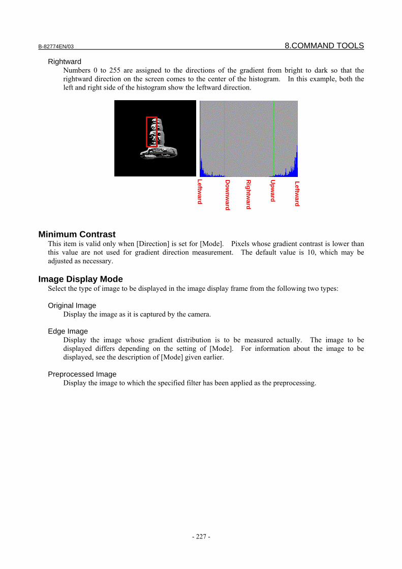
B-82774EN/03 8.COMMAND TOOLS
- 227 -
Rightward Numbers 0 to 255 are assigned to the directions of the gradient from bright to dark so that the rightward direction on the screen comes to the center of the histogram. In this example, both the left and right side of the histogram show the leftward direction.
Minimum Contrast This item is valid only when [Direction] is set for [Mode]. Pixels whose gradient contrast is lower than this value are not used for gradient direction measurement. The default value is 10, which may be adjusted as necessary.
Image Display Mode Select the type of image to be displayed in the image display frame from the following two types: Original Image
Display the image as it is captured by the camera. Edge Image
Display the image whose gradient distribution is to be measured actually. The image to be displayed differs depending on the setting of [Mode]. For information about the image to be displayed, see the description of [Mode] given earlier.
Preprocessed Image
Display the image to which the specified filter has been applied as the preprocessing.
Leftward
Dow
nward
Rightw
ard
Leftward
Upw
ard

8.COMMAND TOOLS B-82774EN/03
- 228 -
8.6.2 Running a Test Run a measurement test to see if the tool can measure the gradient distribution properly.
Snap and Find button The tool snaps an image from the camera and attempts to perform the measurement.
Continuous S+F button The tool repeats the Snap and Find operation.
Find button The tool only performs the measurement without snapping an image from the camera.
Time to Find The time the gradient distribution measurement took is displayed in milliseconds.
Measurement Result Table The following values are displayed. Num. Pixels
Total number of pixels in the area in which the gradient distribution measurement was made. The unit is the pixel. Note that pixels whose contrast is lower than the minimum contrast are excluded from the gradient distribution measurement and not included in the total number.
Maximum
Maximum value in the gradient distribution measurement area. Minimum
Minimum value in the gradient distribution measurement area. Median
Median value in the gradient distribution measurement area.
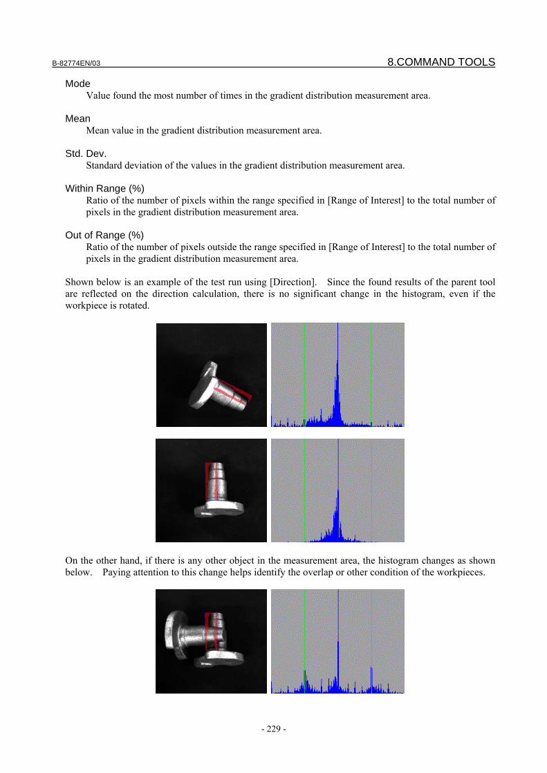
B-82774EN/03 8.COMMAND TOOLS
- 229 -
Mode Value found the most number of times in the gradient distribution measurement area.
Mean
Mean value in the gradient distribution measurement area. Std. Dev.
Standard deviation of the values in the gradient distribution measurement area. Within Range (%)
Ratio of the number of pixels within the range specified in [Range of Interest] to the total number of pixels in the gradient distribution measurement area.
Out of Range (%)
Ratio of the number of pixels outside the range specified in [Range of Interest] to the total number of pixels in the gradient distribution measurement area.
Shown below is an example of the test run using [Direction]. Since the found results of the parent tool are reflected on the direction calculation, there is no significant change in the histogram, even if the workpiece is rotated.
On the other hand, if there is any other object in the measurement area, the histogram changes as shown below. Paying attention to this change helps identify the overlap or other condition of the workpieces.
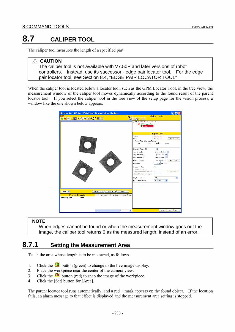
8.COMMAND TOOLS B-82774EN/03
- 230 -
8.7 CALIPER TOOL The caliper tool measures the length of a specified part.
CAUTION The caliper tool is not available with V7.50P and later versions of robot
controllers. Instead, use its successor - edge pair locator tool. For the edge pair locator tool, see Section 8.4, "EDGE PAIR LOCATOR TOOL"
When the caliper tool is located below a locator tool, such as the GPM Locator Tool, in the tree view, the measurement window of the caliper tool moves dynamically according to the found result of the parent locator tool. If you select the caliper tool in the tree view of the setup page for the vision process, a window like the one shown below appears.
NOTE When edges cannot be found or when the measurement window goes out the
image, the caliper tool returns 0 as the measured length, instead of an error.
8.7.1 Setting the Measurement Area Teach the area whose length is to be measured, as follows. 1. Click the button (green) to change to the live image display. 2. Place the workpiece near the center of the camera view. 3. Click the button (red) to snap the image of the workpiece. 4. Click the [Set] button for [Area]. The parent locator tool runs automatically, and a red + mark appears on the found object. If the location fails, an alarm message to that effect is displayed and the measurement area setting is stopped.
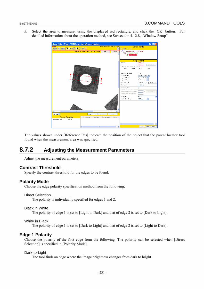
B-82774EN/03 8.COMMAND TOOLS
- 231 -
5. Select the area to measure, using the displayed red rectangle, and click the [OK] button. For detailed information about the operation method, see Subsection 4.12.8, “Window Setup”.
The values shown under [Reference Pos] indicate the position of the object that the parent locator tool found when the measurement area was specified.
8.7.2 Adjusting the Measurement Parameters Adjust the measurement parameters.
Contrast Threshold Specify the contrast threshold for the edges to be found.
Polarity Mode Choose the edge polarity specification method from the following: Direct Selection
The polarity is individually specified for edges 1 and 2. Black in White
The polarity of edge 1 is set to [Light to Dark] and that of edge 2 is set to [Dark to Light]. White in Black
The polarity of edge 1 is set to [Dark to Light] and that of edge 2 is set to [Light to Dark].
Edge 1 Polarity Choose the polarity of the first edge from the following. The polarity can be selected when [Direct Selection] is specified in [Polarity Mode]. Dark-to-Light
The tool finds an edge where the image brightness changes from dark to bright.
8.COMMAND TOOLS B-82774EN/03
- 232 -
Light-to-Dark The tool finds an edge where the image brightness changes from bright to dark.
Edge 2 Polarity
Choose the polarity of the first edge from the following. The polarity can be selected when [Direct Selection] is specified in [Polarity Mode]. Dark-to-Light
The tool finds an edge where the image brightness changes from dark to bright. Light-to-Dark
The tool finds an edge where the image brightness changes from bright to dark.
Standard Length Specify the standard length of the part to be measured (units: pixels).
Tolerance Specify the allowable range of length for the measurement (units: pixels). The measurement is regarded as successful if the distance between the found edges is equal to the reference length plus or minus the allowable range of length.
Reference Length in Pixels Set this item if you want to convert the unit of the measured length to mm. Run a test to measure the length of the workpiece in pixels in the image, then click the Set button to set the length.
Scaled Reference Length Set this item if you want to covert the unit of the measured length to mm. Determine the actual length of the workpiece by means other than iRVision’s caliper tool and enter it into the scaled reference length field.
Display Mode Select one of the following modes for displaying the result after the process is run. Edges
Only the found edges will be displayed. Edge+Arrow
The found edges and the direction in which the found edges are scanned will be displayed. Edges+Proj.+Grad.
The found edges and a graph representing the brightness of the measured part will be displayed. Edges+Proj.+Grad+Arrow
The found edges, the direction in which the found edges are scanned, and a graph representing the brightness of the measured part will be displayed.
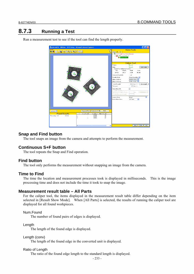
B-82774EN/03 8.COMMAND TOOLS
- 233 -
8.7.3 Running a Test Run a measurement test to see if the tool can find the length properly.
Snap and Find button The tool snaps an image from the camera and attempts to perform the measurement.
Continuous S+F button The tool repeats the Snap and Find operation.
Find button The tool only performs the measurement without snapping an image from the camera.
Time to Find The time the location and measurement processes took is displayed in milliseconds. This is the image processing time and does not include the time it took to snap the image.
Measurement result table – All Parts For the caliper tool, the items displayed in the measurement result table differ depending on the item selected in [Result Show Mode]. When [All Parts] is selected, the results of running the caliper tool are displayed for all found workpieces. Num.Found
The number of found pairs of edges is displayed. Length
The length of the found edge is displayed. Length (conv)
The length of the found edge in the converted unit is displayed. Ratio of Length
The ratio of the found edge length to the standard length is displayed.
8.COMMAND TOOLS B-82774EN/03
- 234 -
Contrast
The contrast of the found edge is displayed.
Measurement result table – All Edge Pairs For the caliper tool, the items displayed in the measurement result table differ depending on the item selected in [Result Show Mode]. When [All Edge pairs] is selected, all pairs of edges found in a specific workpiece are displayed. Show ALL
All pairs of edges found in the specified workpiece are displayed. Show Almost Found
When this check box is checked, each pair of edges the distance between which is equal to the standard length plus or minus the allowable range of length is displayed.
Length
The length of the found edge is displayed. Length (conv)
The length of the found edge in the converted unit is displayed. Edge1 Row, Edge1 Col, Edge1 Pol
The coordinates (units: pixels) and polarity of edge 1 are displayed. Edge1 Row, Edge1 Col, Edge1 Pol
The coordinates (units: pixels) and polarity of edge 2 are displayed. Contrast
The contrast of the found edge is displayed.
Found Length If more than two edges are found, the tool picks out a pair of edges that best match the specified measurement parameters and measures the distance between these two edges (units: pixels).
Measurement Result Table The following values are displayed. Row, Column
Coordinate values of the found edge (units: pixels). Contrast
Contrast of the found edge.
8.8 CONDITIONAL EXECUTION TOOL The conditional execution tool evaluates the result of the histogram or other tool based on specified conditions and, only if the conditions are met, executes the specified processing. If you select the conditional execution tool in the tree view of the setup page for the vision process, a window like the one shown below appears.
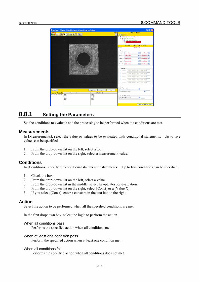
B-82774EN/03 8.COMMAND TOOLS
- 235 -
8.8.1 Setting the Parameters Set the conditions to evaluate and the processing to be performed when the conditions are met.
Measurements In [Measurements], select the value or values to be evaluated with conditional statements. Up to five values can be specified. 1. From the drop-down list on the left, select a tool. 2. From the drop-down list on the right, select a measurement value.
Conditions In [Conditions], specify the conditional statement or statements. Up to five conditions can be specified. 1. Check the box. 2. From the drop-down list on the left, select a value. 3. From the drop-down list in the middle, select an operator for evaluation. 4. From the drop-down list on the right, select [Const] or a [Value X]. 5. If you select [Const], enter a constant in the text box to the right.
Action Select the action to be performed when all the specified conditions are met. In the first dropdown box, select the logic to perform the action. When all conditions pass
Performs the specified action when all conditions met. When at least one condition pass
Perform the specified action when at least one condition met. When all conditions fail
Performs the specified action when all conditions does not met.
8.COMMAND TOOLS B-82774EN/03
- 236 -
When at least one condition fail Performs the specified action when at least one condition not met.
In the next dropdown box, select an action to perform. Invalidate this pose
Invalidate this position. Add the following value to model ID
Add the specified value to the model ID. Change the found angle by
Add the specified value in degrees to the found angle.
When undetermined In [When undetermined], specify the action to be taken when whether the conditions are met cannot be determined. This can happen when there is no measurement value to evaluate - e.g., when the locator tool specified in [Value1] has failed to find the workpiece. Select one of the following options to specify the action to be taken: Invalidate this pose
Invalidate this position. Add the following value to model ID
Add the specified value to the model ID.
8.8.2 Running a Test Run a test to see if the tool can evaluate the conditions properly.
Snap and Find button The tool snaps an image from the camera and attempts to runs the test.
Continuous S+F button The tool repeats the Snap and Find operation.
B-82774EN/03 8.COMMAND TOOLS
- 237 -
Find button
The tool only performs the measurement without snapping an image from the camera.
Result In [Result], [PASS] is displayed if all of the specified conditions are met and [FAIL] is displayed if any of the specified conditions are not met.
Execution Result Table The measurement values for [Value 1] to [Value 5] and the PASS/FAIL evaluation results for [Condition 1] to [Condition 5] are displayed.
8.9 MULTI-LOCATOR TOOL The Multi-locator tool changes the locator tool to be executed, according to the value set in a robot register. If you select the Multi-locator tool in the tree view of the setup page of the vision process, a window like the one shown below appears.
8.9.1 Adding Child Tools Add locator tools you want to use according to the value of the register as child tools of the Multi-locator tool. In the figure below, GPM Locator Tool 1 is executed when the register value is 1; GPM Locator Tool 2 is executed when it is 2.
8.COMMAND TOOLS B-82774EN/03
- 238 -
CAUTION The Multi-locator tool cannot contain different types of locator tool. For
example, you cannot mix a blob locator tool to a GPM Locator Tool under the multi-locator tool.
8.9.2 Setting the Register Specify the register you want to use to change the locator tool.
Location Tool Index Register Specify the number of the register you want to use to change the tool.
Index Register Value The value currently set in the register specified in [Location Tool Index Register] is displayed. When the value is changed, the value of the register of the robot controller is also updated automatically. This function is useful when you change the locator tool and run a test.
Index Register Comment The comment currently set for the register specified in [Location Tool Index Register] is displayed.
8.9.3 Running a Test Test to see if the tool can find workpieces properly.
Snap and Find button The tool snaps an image from the camera and attempts to find a workpiece.
Continuous S+F button The tool repeats the Snap and Find operation.
Find button The tool only attempts to perform the measurement without snapping an image.
B-82774EN/03 8.COMMAND TOOLS
- 239 -
Found
The number of found workpieces is displayed.
Time to Find The time the location process took is displayed in milliseconds. This is the image processing time and does not include the time it took to snap the image.
Found Results table The items displayed differ depending on the tools set as child tools of the Multi-locator tool. For the explanation of each measured value, see the pages describing the set child tools.
8.10 MULTI-WINDOW TOOL The multi-window tool changes the search window to be used, according to the value set in a robot register. If you select the multi-window tool in the tree view of the setup page of the vision process, a window like the one shown below appears.
8.10.1 Setting the Register Specify the register you want to use to change the window.
Window Index Register Specify the number of the register you want to use to change the window.
Index Register Value The value currently set in the specified register is displayed. When the value is changed, the value of the register of the robot controller is also updated automatically. This function is useful when you change the window and run a test.
Index Register Comment The comment currently set for the specified register is displayed.
8.COMMAND TOOLS B-82774EN/03
- 240 -
Add Index to Model ID
Specify whether to add the value of the specified register to the model ID. When this check box is checked, the value of the specified register is added to the model ID.
8.10.2 Setting a Window Create a new window, and delete or change a window.
Creating a new window Click the button. A new window is created.
Deleting a window Click the button. The window is deleted.
Moving up Click the button. You can change the window.
Moving down Click the button. You can change the window.
Search Window Specify the range of the area of the image to be searched. The default value is the entire image. To change the search window, click the [Set Search Win.] button. When a rectangle appears on the image, change the search window. For detailed information about the operation method, see Subsection 4.12.8, “Window Setup”.
Run-Time Mask Specify an area of the search window that you do not want processed, as an arbitrary geometry. Use this function when you want to specify a search window of an arbitrary geometry, such as a circle or donut-shaped window. The filled area will be masked in the rectangle specified as the search window and will not be subject to the image processing. To change the run-time mask, click the [Edit RT Mask] button. For detailed information about the operation method, see Subsection 4.12.9, “Editing Masks”.
B-82774EN/03 8.COMMAND TOOLS
- 241 -
8.10.3 Running a Test Test to see if the tool can find workpieces properly.
Snap and Find button The tool snaps an image from the camera and attempts to find a workpiece.
Continuous S+F button The tool repeats the Snap and Find operation.
Find button The tool only attempts to perform the measurement without snapping an image.
Found The number of found workpieces is displayed.
Time to Find The time the location process took is displayed in milliseconds. This is the image processing time and does not include the time it took to snap the image.
Found Results table The items displayed differ depending on the tools set as child tools of the multi-window tool. For the explanation of each measured value, see the pages describing the set child tools.
8.11 POSITION ADJUSTMENT TOOL The position adjustment tool fine-adjusts the position found by the parent locator tool using the found result of its child locator tools. If it is difficult to find the position or angle accurately for the entire workpiece, find the entire workpiece using the parent locator tool, then find some parts with which positioning can be made easy, such as holes, using its child locator tools, and modify the entire found position for more accurate offset data. If you select the position adjustment tool in the tree view of the setup page of the vision process, a window like the one shown below appears.
8.COMMAND TOOLS B-82774EN/03
- 242 -
8.11.1 Setting Parameters Set the parameters.
Selecting tools Up to five tools can be specified. Select a tool you want to use the position adjustment of the parent locator tool from the drop-down list.
Setting the Reference Position 1. Click the button (green) to change to the live image display. 2. Place the workpiece at a position where the parent and child locator tools can find it. 3. Click the button (red) to snap the image of the workpiece. 4. Click the [Set Ref. Pos.] button. 5. The parent and child locator tools find the workpiece and the position found by each tool is set as the
reference position.
8.11.2 Setting the Parameters
Fit Error Limit This is the threshold for the combine error (units: pixels) between the point found when the reference position is set and the point found when the detection process is executed actually. If the combine error exceeds this threshold, the workpiece is not found. When this check box is unchecked, the combine error is not checked.
Conditions Specify the value(s) to be adjusted. Adjust Location
The coordinates (Row and Column) of the position found by the parent locator tool are adjusted. Adjust Angle
The angle found by the parent locator tool is adjusted.
B-82774EN/03 8.COMMAND TOOLS
- 243 -
CAUTION
To adjust both the position and orientation, at least two child locator tools must be specified. If only one child locator tool is set, either the position or orientation can be adjusted only.
8.11.3 Running a Test Test to see if the tool can adjust the position properly.
Snap and Find button The tool snaps an image from the camera and attempts to find a workpiece.
Continuous S+F button The tool repeats the Snap and Find operation.
Find button The tool only attempts to perform the measurement without snapping an image.
Found The number of found workpieces is displayed.
Time to Find The time the location and position adjustment amount calculation processes took is displayed in milliseconds. This is the processing time and does not include the time it took to snap the image.
Found result table The following values are displayed. Row
Adjustment amount in the virtual direction in the window (units: pixels).
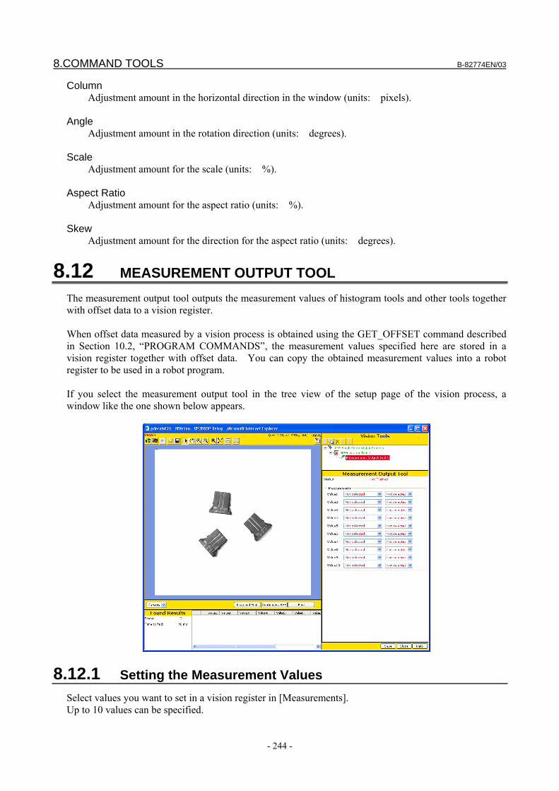
8.COMMAND TOOLS B-82774EN/03
- 244 -
Column Adjustment amount in the horizontal direction in the window (units: pixels).
Angle
Adjustment amount in the rotation direction (units: degrees). Scale
Adjustment amount for the scale (units: %). Aspect Ratio
Adjustment amount for the aspect ratio (units: %). Skew
Adjustment amount for the direction for the aspect ratio (units: degrees).
8.12 MEASUREMENT OUTPUT TOOL The measurement output tool outputs the measurement values of histogram tools and other tools together with offset data to a vision register. When offset data measured by a vision process is obtained using the GET_OFFSET command described in Section 10.2, “PROGRAM COMMANDS”, the measurement values specified here are stored in a vision register together with offset data. You can copy the obtained measurement values into a robot register to be used in a robot program. If you select the measurement output tool in the tree view of the setup page of the vision process, a window like the one shown below appears.
8.12.1 Setting the Measurement Values Select values you want to set in a vision register in [Measurements]. Up to 10 values can be specified.
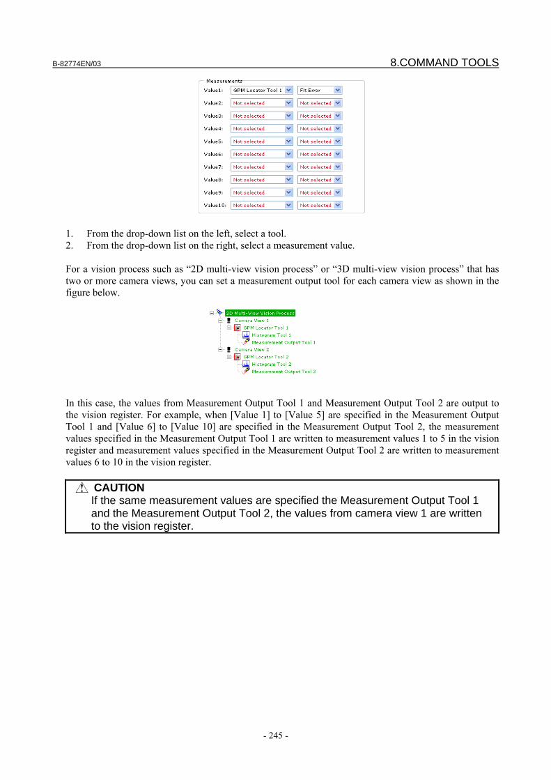
B-82774EN/03 8.COMMAND TOOLS
- 245 -
1. From the drop-down list on the left, select a tool. 2. From the drop-down list on the right, select a measurement value. For a vision process such as “2D multi-view vision process” or “3D multi-view vision process” that has two or more camera views, you can set a measurement output tool for each camera view as shown in the figure below.
In this case, the values from Measurement Output Tool 1 and Measurement Output Tool 2 are output to the vision register. For example, when [Value 1] to [Value 5] are specified in the Measurement Output Tool 1 and [Value 6] to [Value 10] are specified in the Measurement Output Tool 2, the measurement values specified in the Measurement Output Tool 1 are written to measurement values 1 to 5 in the vision register and measurement values specified in the Measurement Output Tool 2 are written to measurement values 6 to 10 in the vision register.
CAUTION If the same measurement values are specified the Measurement Output Tool 1
and the Measurement Output Tool 2, the values from camera view 1 are written to the vision register.
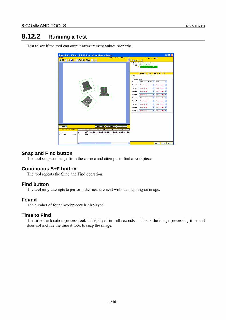
8.COMMAND TOOLS B-82774EN/03
- 246 -
8.12.2 Running a Test Test to see if the tool can output measurement values properly.
Snap and Find button The tool snaps an image from the camera and attempts to find a workpiece.
Continuous S+F button The tool repeats the Snap and Find operation.
Find button The tool only attempts to perform the measurement without snapping an image.
Found The number of found workpieces is displayed.
Time to Find The time the location process took is displayed in milliseconds. This is the image processing time and does not include the time it took to snap the image.
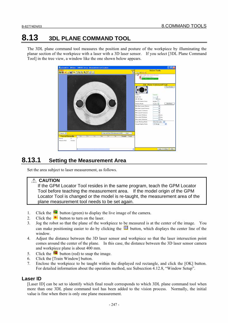
B-82774EN/03 8.COMMAND TOOLS
- 247 -
8.13 3DL PLANE COMMAND TOOL The 3DL plane command tool measures the position and posture of the workpiece by illuminating the planar section of the workpiece with a laser with a 3D laser sensor. If you select [3DL Plane Command Tool] in the tree view, a window like the one shown below appears.
8.13.1 Setting the Measurement Area Set the area subject to laser measurement, as follows.
CAUTION If the GPM Locator Tool resides in the same program, teach the GPM Locator
Tool before teaching the measurement area. If the model origin of the GPM Locator Tool is changed or the model is re-taught, the measurement area of the plane measurement tool needs to be set again.
1. Click the button (green) to display the live image of the camera. 2. Click the button to turn on the laser. 3. Jog the robot so that the plane of the workpiece to be measured is at the center of the image. You
can make positioning easier to do by clicking the button, which displays the center line of the window.
4. Adjust the distance between the 3D laser sensor and workpiece so that the laser intersection point comes around the center of the plane. In this case, the distance between the 3D laser sensor camera and workpiece plane is about 400 mm.
5. Click the button (red) to snap the image. 6. Click the [Train Window] button. 7. Enclose the workpiece to be taught within the displayed red rectangle, and click the [OK] button.
For detailed information about the operation method, see Subsection 4.12.8, “Window Setup”.
Laser ID [Laser ID] can be set to identify which final result corresponds to which 3DL plane command tool when more than one 3DL plane command tool has been added to the vision process. Normally, the initial value is fine when there is only one plane measurement.
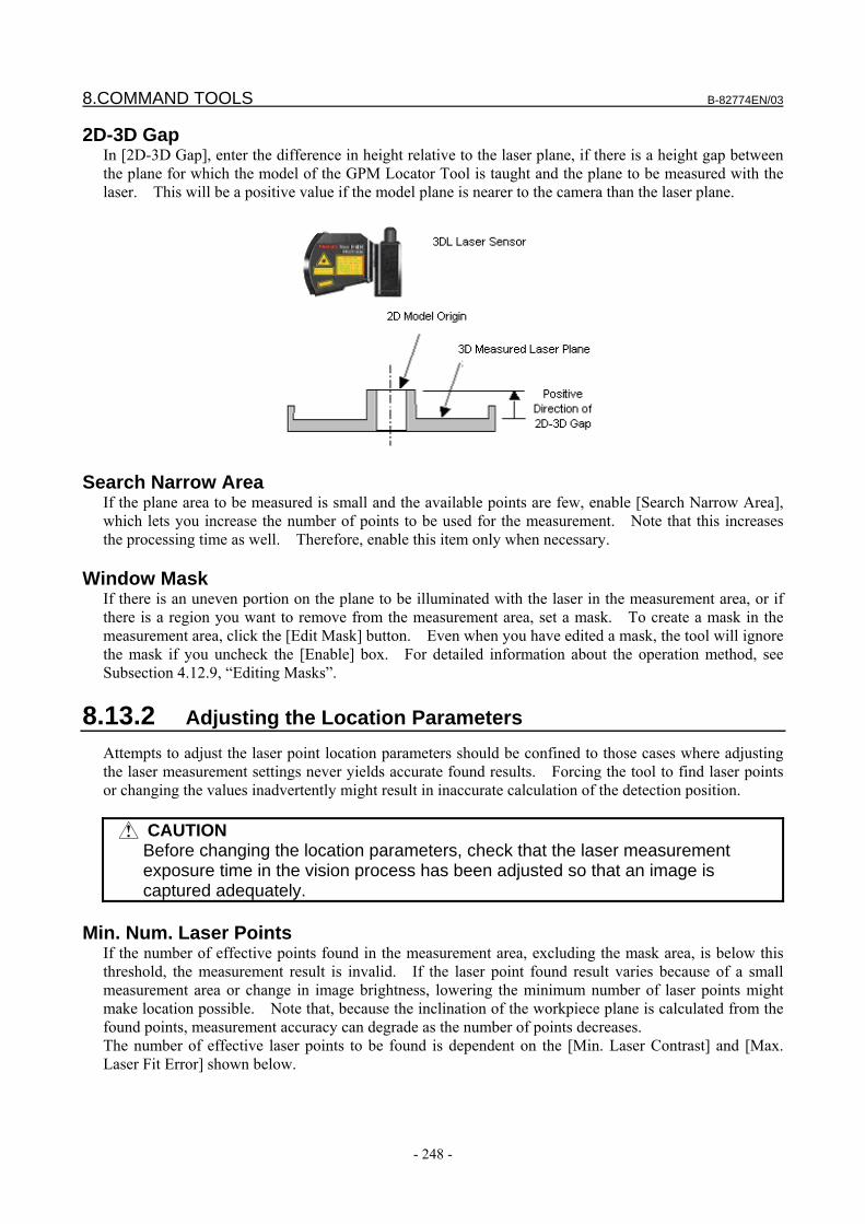
8.COMMAND TOOLS B-82774EN/03
- 248 -
2D-3D Gap In [2D-3D Gap], enter the difference in height relative to the laser plane, if there is a height gap between the plane for which the model of the GPM Locator Tool is taught and the plane to be measured with the laser. This will be a positive value if the model plane is nearer to the camera than the laser plane.
Search Narrow Area
If the plane area to be measured is small and the available points are few, enable [Search Narrow Area], which lets you increase the number of points to be used for the measurement. Note that this increases the processing time as well. Therefore, enable this item only when necessary.
Window Mask If there is an uneven portion on the plane to be illuminated with the laser in the measurement area, or if there is a region you want to remove from the measurement area, set a mask. To create a mask in the measurement area, click the [Edit Mask] button. Even when you have edited a mask, the tool will ignore the mask if you uncheck the [Enable] box. For detailed information about the operation method, see Subsection 4.12.9, “Editing Masks”.
8.13.2 Adjusting the Location Parameters Attempts to adjust the laser point location parameters should be confined to those cases where adjusting the laser measurement settings never yields accurate found results. Forcing the tool to find laser points or changing the values inadvertently might result in inaccurate calculation of the detection position.
CAUTION Before changing the location parameters, check that the laser measurement
exposure time in the vision process has been adjusted so that an image is captured adequately.
Min. Num. Laser Points
If the number of effective points found in the measurement area, excluding the mask area, is below this threshold, the measurement result is invalid. If the laser point found result varies because of a small measurement area or change in image brightness, lowering the minimum number of laser points might make location possible. Note that, because the inclination of the workpiece plane is calculated from the found points, measurement accuracy can degrade as the number of points decreases. The number of effective laser points to be found is dependent on the [Min. Laser Contrast] and [Max. Laser Fit Error] shown below.
B-82774EN/03 8.COMMAND TOOLS
- 249 -
Min. Laser Contrast This is the threshold for finding points of the laser applied to the measurement area, excluding the mask area.
Max. Line Fit Error When a straight line is formed by points of the laser applied to the measurement area, excluding the mask area, each point is regarded as an effective point as long as its deviation from the straight line is within this margin of error expressed in pixels. When the plane to be measured is textured, as in a casting surface, increasing this value slightly might allow the tool to find more effective points. Note that setting too large a value might degrade accuracy.
Max. Lines Distance Theoretically, the straight line formed by laser points calculated from each laser slit intersects at the intersection point of the laser applied to the workpiece plane. In actuality, however, the distance between the two lines rarely becomes 0 because of calibration error or measurement error. The maximum LL distance is the threshold for the shortest distance of the straight line orthogonal to the two straight lines. The initial value is set to 3.0 mm. If the need arises to set a distance longer than this, the 3D laser sensor might not have been calibrated properly. Although the maximum LL distance can be increased on a temporary basis as long as the position offset of the robot is within the required accuracy range, it is recommended to perform automatic re-calibration as appropriate.
Laser Plotting Mode Select how the laser label is to be displayed on the image when the process is run. Plot CW Mode
The laser label is displayed clockwise. Plot CCW Mode
The laser label is displayed counterclockwise. Plot Nothing
The laser label is not displayed.
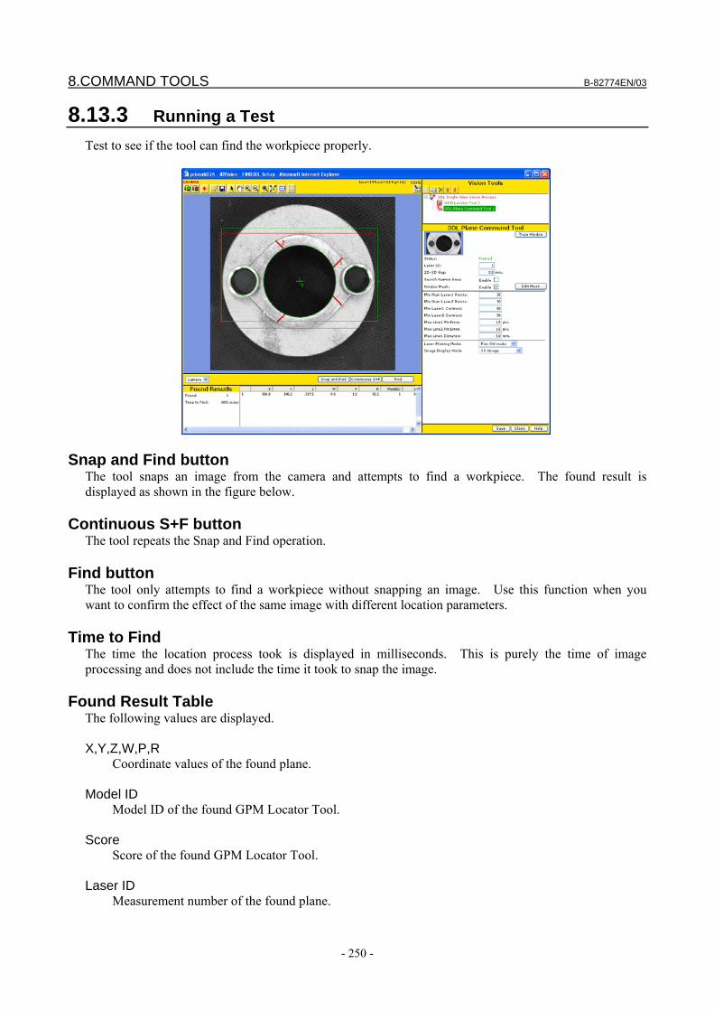
8.COMMAND TOOLS B-82774EN/03
- 250 -
8.13.3 Running a Test Test to see if the tool can find the workpiece properly.
Snap and Find button The tool snaps an image from the camera and attempts to find a workpiece. The found result is displayed as shown in the figure below.
Continuous S+F button The tool repeats the Snap and Find operation.
Find button The tool only attempts to find a workpiece without snapping an image. Use this function when you want to confirm the effect of the same image with different location parameters.
Time to Find The time the location process took is displayed in milliseconds. This is purely the time of image processing and does not include the time it took to snap the image.
Found Result Table The following values are displayed. X,Y,Z,W,P,R
Coordinate values of the found plane. Model ID
Model ID of the found GPM Locator Tool. Score
Score of the found GPM Locator Tool. Laser ID
Measurement number of the found plane.
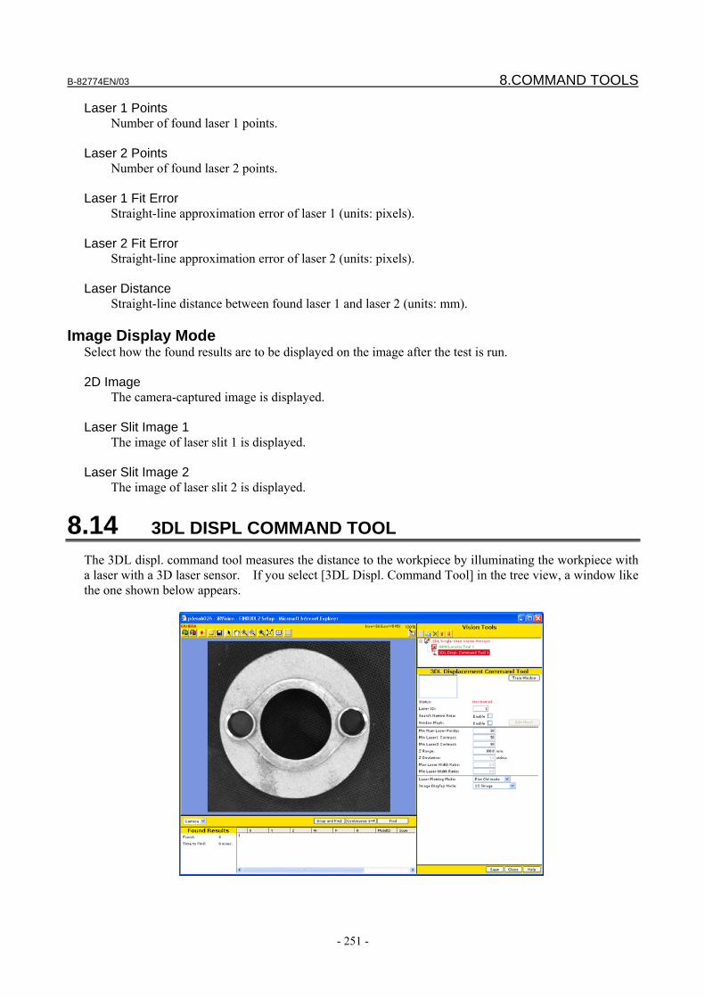
B-82774EN/03 8.COMMAND TOOLS
- 251 -
Laser 1 Points Number of found laser 1 points.
Laser 2 Points
Number of found laser 2 points. Laser 1 Fit Error
Straight-line approximation error of laser 1 (units: pixels). Laser 2 Fit Error
Straight-line approximation error of laser 2 (units: pixels). Laser Distance
Straight-line distance between found laser 1 and laser 2 (units: mm).
Image Display Mode Select how the found results are to be displayed on the image after the test is run. 2D Image
The camera-captured image is displayed. Laser Slit Image 1
The image of laser slit 1 is displayed. Laser Slit Image 2
The image of laser slit 2 is displayed.
8.14 3DL DISPL COMMAND TOOL The 3DL displ. command tool measures the distance to the workpiece by illuminating the workpiece with a laser with a 3D laser sensor. If you select [3DL Displ. Command Tool] in the tree view, a window like the one shown below appears.
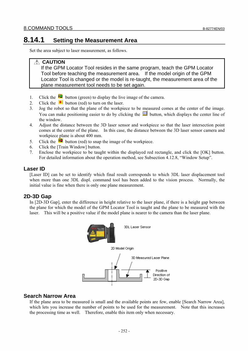
8.COMMAND TOOLS B-82774EN/03
- 252 -
8.14.1 Setting the Measurement Area Set the area subject to laser measurement, as follows.
CAUTION If the GPM Locator Tool resides in the same program, teach the GPM Locator
Tool before teaching the measurement area. If the model origin of the GPM Locator Tool is changed or the model is re-taught, the measurement area of the plane measurement tool needs to be set again.
1. Click the button (green) to display the live image of the camera. 2. Click the button (red) to turn on the laser. 3. Jog the robot so that the plane of the workpiece to be measured comes at the center of the image.
You can make positioning easier to do by clicking the button, which displays the center line of the window.
4. Adjust the distance between the 3D laser sensor and workpiece so that the laser intersection point comes at the center of the plane. In this case, the distance between the 3D laser sensor camera and workpiece plane is about 400 mm.
5. Click the button (red) to snap the image of the workpiece. 6. Click the [Train Window] button. 7. Enclose the workpiece to be taught within the displayed red rectangle, and click the [OK] button.
For detailed information about the operation method, see Subsection 4.12.8, “Window Setup”.
Laser ID [Laser ID] can be set to identify which final result corresponds to which 3DL laser displacement tool when more than one 3DL displ. command tool has been added to the vision process. Normally, the initial value is fine when there is only one plane measurement.
2D-3D Gap In [2D-3D Gap], enter the difference in height relative to the laser plane, if there is a height gap between the plane for which the model of the GPM Locator Tool is taught and the plane to be measured with the laser. This will be a positive value if the model plane is nearer to the camera than the laser plane.
Search Narrow Area
If the plane area to be measured is small and the available points are few, enable [Search Narrow Area], which lets you increase the number of points to be used for the measurement. Note that this increases the processing time as well. Therefore, enable this item only when necessary.
B-82774EN/03 8.COMMAND TOOLS
- 253 -
Window Mask If there is an uneven portion on the plane to be illuminated with the laser in the measurement area, or if there is a region you want to remove from the measurement area, set a mask. To create a mask in the measurement area, click the [Edit Mask] button. Even when you have edited a mask, the tool will ignore the mask if you uncheck the [Enable] box. For detailed information about the operation method, see Subsection 4.12.8, “Edit Masks”.
8.14.2 Adjusting the Location Parameters Attempts to adjust the laser point location parameters should be confined to those cases where adjusting the laser measurement settings never yields accurate found results. Forcing the tool to find laser points or changing the values inadvertently might result in inaccurate calculation of the detection position.
CAUTION Before changing the location parameters, check that the laser measurement
exposure time in the vision process has been adjusted so that an image is captured adequately.
Min. Num. Laser Points
If the number of effective points found in the measurement area, excluding the mask area, is below this threshold, the measurement result is invalid. If the laser point found result varies because of a small measurement area or change in image brightness, lowering the minimum number of laser points might make location possible. Note that, because the inclination of the workpiece plane is calculated from the found points, measurement accuracy can degrade as the number of points decreases. The number of effective laser points to be found is dependent on the [Min. Laser Contrast] described below.
Min. Laser Contrast This is the threshold for finding points of the laser applied to the measurement area, excluding the mask area.
Z Range This is the range of Z-direction points to be used for calculation from the average value of laser points. Set this to a value between 0 and 200.
Laser Plotting Mode Select how the laser label is to be displayed on the image when the process is run. Plot CW Mode
The laser label is displayed clockwise. Plot CCW Mode
The laser label is displayed counterclockwise. Plot Nothing
The laser label is not displayed.
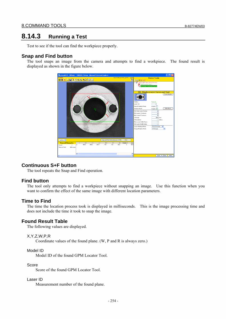
8.COMMAND TOOLS B-82774EN/03
- 254 -
8.14.3 Running a Test Test to see if the tool can find the workpiece properly.
Snap and Find button The tool snaps an image from the camera and attempts to find a workpiece. The found result is displayed as shown in the figure below.
Continuous S+F button The tool repeats the Snap and Find operation.
Find button The tool only attempts to find a workpiece without snapping an image. Use this function when you want to confirm the effect of the same image with different location parameters.
Time to Find The time the location process took is displayed in milliseconds. This is the image processing time and does not include the time it took to snap the image.
Found Result Table The following values are displayed. X,Y,Z,W,P,R
Coordinate values of the found plane. (W, P and R is always zero.) Model ID
Model ID of the found GPM Locator Tool. Score
Score of the found GPM Locator Tool. Laser ID
Measurement number of the found plane.
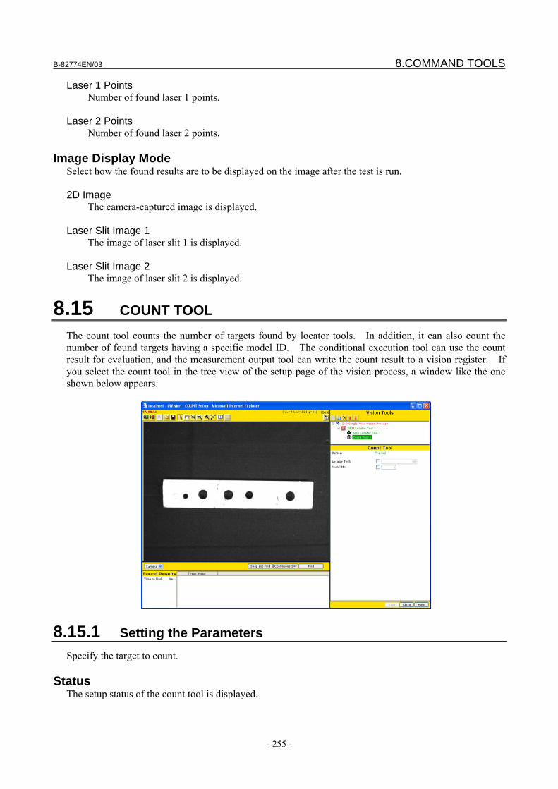
B-82774EN/03 8.COMMAND TOOLS
- 255 -
Laser 1 Points Number of found laser 1 points.
Laser 2 Points
Number of found laser 2 points.
Image Display Mode Select how the found results are to be displayed on the image after the test is run. 2D Image
The camera-captured image is displayed. Laser Slit Image 1
The image of laser slit 1 is displayed. Laser Slit Image 2
The image of laser slit 2 is displayed.
8.15 COUNT TOOL The count tool counts the number of targets found by locator tools. In addition, it can also count the number of found targets having a specific model ID. The conditional execution tool can use the count result for evaluation, and the measurement output tool can write the count result to a vision register. If you select the count tool in the tree view of the setup page of the vision process, a window like the one shown below appears.
8.15.1 Setting the Parameters Specify the target to count.
Status The setup status of the count tool is displayed.
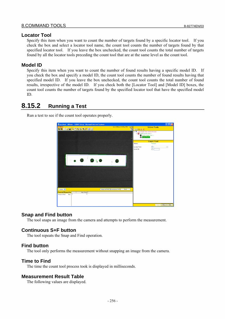
8.COMMAND TOOLS B-82774EN/03
- 256 -
Locator Tool Specify this item when you want to count the number of targets found by a specific locator tool. If you check the box and select a locator tool name, the count tool counts the number of targets found by that specified locator tool. If you leave the box unchecked, the count tool counts the total number of targets found by all the locator tools preceding the count tool that are at the same level as the count tool.
Model ID Specify this item when you want to count the number of found results having a specific model ID. If you check the box and specify a model ID, the count tool counts the number of found results having that specified model ID. If you leave the box unchecked, the count tool counts the total number of found results, irrespective of the model ID. If you check both the [Locator Tool] and [Model ID] boxes, the count tool counts the number of targets found by the specified locator tool that have the specified model ID.
8.15.2 Running a Test Run a test to see if the count tool operates properly.
Snap and Find button The tool snaps an image from the camera and attempts to perform the measurement.
Continuous S+F button The tool repeats the Snap and Find operation.
Find button The tool only performs the measurement without snapping an image from the camera.
Time to Find The time the count tool process took is displayed in milliseconds.
Measurement Result Table The following values are displayed.
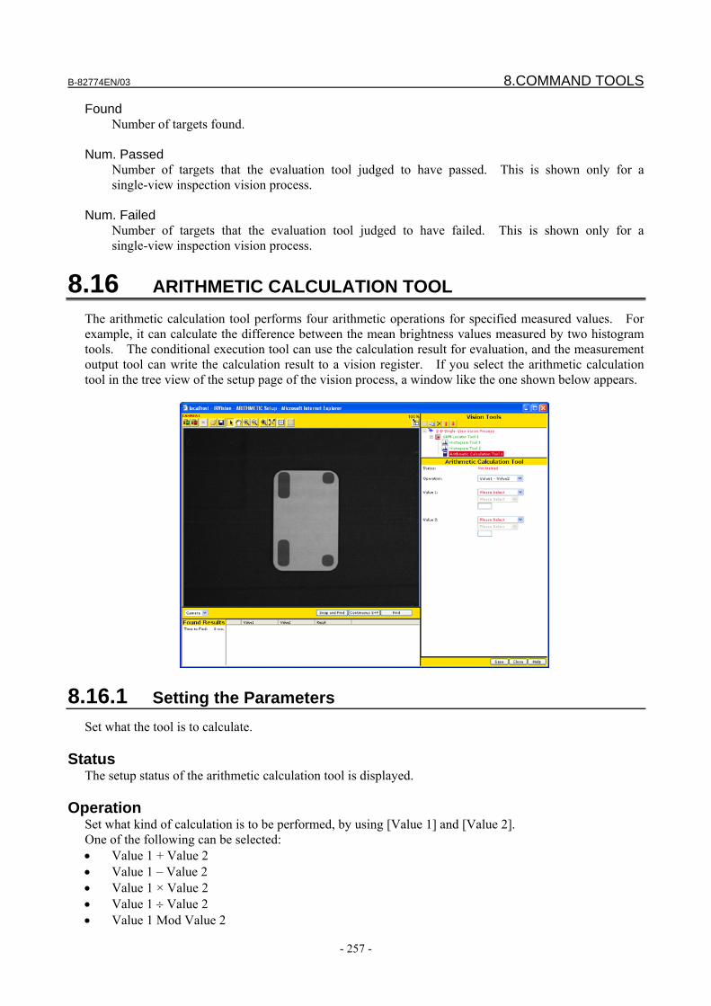
B-82774EN/03 8.COMMAND TOOLS
- 257 -
Found Number of targets found.
Num. Passed
Number of targets that the evaluation tool judged to have passed. This is shown only for a single-view inspection vision process.
Num. Failed
Number of targets that the evaluation tool judged to have failed. This is shown only for a single-view inspection vision process.
8.16 ARITHMETIC CALCULATION TOOL The arithmetic calculation tool performs four arithmetic operations for specified measured values. For example, it can calculate the difference between the mean brightness values measured by two histogram tools. The conditional execution tool can use the calculation result for evaluation, and the measurement output tool can write the calculation result to a vision register. If you select the arithmetic calculation tool in the tree view of the setup page of the vision process, a window like the one shown below appears.
8.16.1 Setting the Parameters Set what the tool is to calculate.
Status The setup status of the arithmetic calculation tool is displayed.
Operation Set what kind of calculation is to be performed, by using [Value 1] and [Value 2]. One of the following can be selected: • Value 1 + Value 2 • Value 1 – Value 2 • Value 1 × Value 2 • Value 1 ÷ Value 2 • Value 1 Mod Value 2
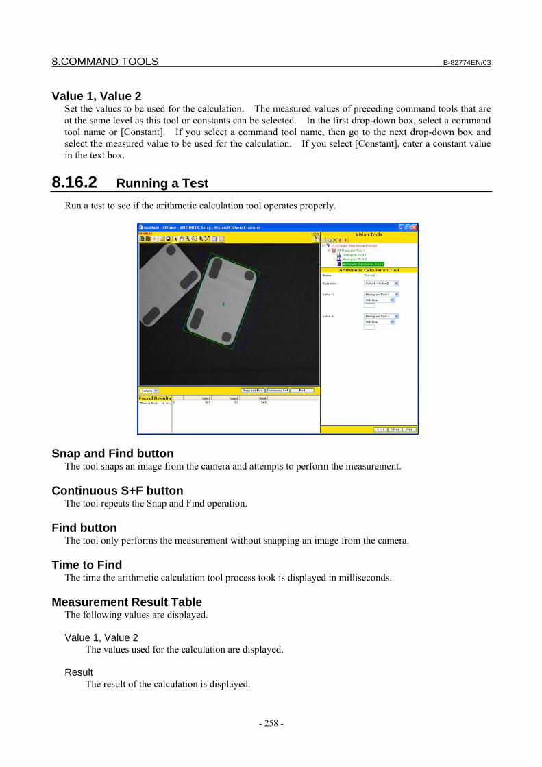
8.COMMAND TOOLS B-82774EN/03
- 258 -
Value 1, Value 2
Set the values to be used for the calculation. The measured values of preceding command tools that are at the same level as this tool or constants can be selected. In the first drop-down box, select a command tool name or [Constant]. If you select a command tool name, then go to the next drop-down box and select the measured value to be used for the calculation. If you select [Constant], enter a constant value in the text box.
8.16.2 Running a Test Run a test to see if the arithmetic calculation tool operates properly.
Snap and Find button The tool snaps an image from the camera and attempts to perform the measurement.
Continuous S+F button The tool repeats the Snap and Find operation.
Find button The tool only performs the measurement without snapping an image from the camera.
Time to Find The time the arithmetic calculation tool process took is displayed in milliseconds.
Measurement Result Table The following values are displayed. Value 1, Value 2
The values used for the calculation are displayed. Result
The result of the calculation is displayed.
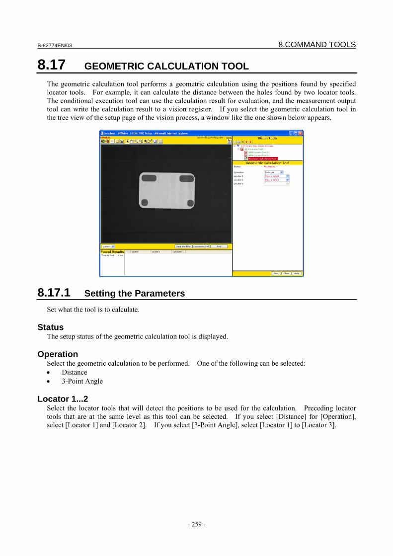
B-82774EN/03 8.COMMAND TOOLS
- 259 -
8.17 GEOMETRIC CALCULATION TOOL The geometric calculation tool performs a geometric calculation using the positions found by specified locator tools. For example, it can calculate the distance between the holes found by two locator tools. The conditional execution tool can use the calculation result for evaluation, and the measurement output tool can write the calculation result to a vision register. If you select the geometric calculation tool in the tree view of the setup page of the vision process, a window like the one shown below appears.
8.17.1 Setting the Parameters Set what the tool is to calculate.
Status The setup status of the geometric calculation tool is displayed.
Operation Select the geometric calculation to be performed. One of the following can be selected: • Distance • 3-Point Angle
Locator 1...2 Select the locator tools that will detect the positions to be used for the calculation. Preceding locator tools that are at the same level as this tool can be selected. If you select [Distance] for [Operation], select [Locator 1] and [Locator 2]. If you select [3-Point Angle], select [Locator 1] to [Locator 3].

8.COMMAND TOOLS B-82774EN/03
- 260 -
8.17.2 Running a Test Run a test to see if the geometric calculation tool operates properly.
Snap and Find button The tool snaps an image from the camera and attempts to perform the measurement.
Continuous S+F button The tool repeats the Snap and Find operation.
Find button The tool only performs the measurement without snapping an image from the camera.
Time to Find The time the geometric calculation tool process took is displayed in milliseconds.
Measurement Result Table The following values are displayed. Locator 1, Locator 2
The positions used for the calculation are displayed. The unit is the pixel. Result
The values used for the calculation are displayed.
B-82774EN/03 8.COMMAND TOOLS
- 261 -
8.18 STATISTIC CALCULATION TOOL The statistic calculation tool performs a statistic calculation for the measured values of targets found by a specified locator tool. For example, when the blob locator tool has found five blobs, it can calculate the average area or standard deviation of the five blobs. The conditional execution tool can use the calculation result for evaluation, and the measurement output tool can write the calculation result to a vision register. If you select the statistic calculation tool in the tree view of the setup page of the vision process, a window like the one shown below appears.
8.18.1 Setting the Parameters Set what the tool is to calculate.
Status The setup status of the statistic calculation tool is displayed.
Locator Select the name of the locator tool from which to obtain measured values. Only a locator at the same level and above the statistical calculation tool can be selected.
Measurement Select the measured value for which the statistic calculation is to be performed.
8.COMMAND TOOLS B-82774EN/03
- 262 -
8.18.2 Running a Test Run a test to see if the statistic calculation tool operates properly.
Snap and Find button The tool snaps an image from the camera and attempts to perform the measurement.
Continuous S+F button The tool repeats the Snap and Find operation.
Find button The tool only performs the measurement without snapping an image from the camera.
Time to Find The time the statistic calculation tool process took is displayed in milliseconds.
Measurement Result Table The following values are displayed. Maximum
Maximum value of the selected measured values. Minimum
Minimum value of the selected measured values. Mean
Mean value of the selected measured values. Deviation
Standard deviation of the selected measured values. Total
Total of the selected measured values.
B-82774EN/03 8.COMMAND TOOLS
- 263 -
8.19 WINDOW SHIFT TOOL The window shift tool dynamically shifts a locator tool window or measurement tool window based on the result of a locator tool or another vision process. For example, when you use an application that retrieves workpieces from a basket or rack, you may set the tool to shift the search window of the locator tool based on the position of the basket or rack, thereby preventing objects outside the basket or rack from being found inadvertently. Place the window shift tool directly below the vision process. The windows of the locator tools and measurement tools that are at the same level as the window shift tool and that are inserted below the window shift tool are shifted according to the window shift tool settings.
If you select the window shift tool in the tree view of the setup page of the vision process, a window like the one shown below appears.
8.19.1 Setting the Parameters Set the parameters.
Mode Select the window shift mode from the following: Locator Tool
A locator tool is placed as a child tool of the window shift tool, which in turn shifts windows based on the found results of that locator tool. Use this mode when the locator tool can find the basket and the workpieces in the same field of view..
Other VP Result
The tool shifts windows based on the found results of another vision process that are stored in a vision register. Use this mode when you want to use different exposure times when finding the basket then when finding the workpieces in it. A vision process for finding the workpieces and for
8.COMMAND TOOLS B-82774EN/03
- 264 -
the basket needs to be prepared separately. In cases where the position of the basket changes only when it is replaced, rather than every time a workpiece is found, you can reduce the cycle time by having the system run the vision process for finding the basket only when the basket is replaced.
The parameters other than [Mode] depend on the mode you select.
8.19.1.1 Shifting windows based on a locator tool's results When windows are shifted based on the found results of a locator tool, the only parameter to set is the [Mode], which is set to “locator tool”. Insert a locator tool as a child tool of the window shift tool, and teach a model pattern of the child locator tool.
Setting the Reference Position Once you teach a command tool that is at the same level and below the window shift tool, the child locator tool of the window shift tool automatically runs. The position found by the child locator tool of the window shift tool is automatically saved as the reference position for shifting the window of the taught command tool. The saved window shift reference position is displayed as follows (shown below is an example of the GPM locator tool).
8.19.1.2 Shifting windows based on another vision process' results When shifting windows based on another vision process' results, make the settings as follows.
Vision Register Number Specify the number of the vision register that stores the vision process results to be used for shifting windows. Make sure that the vision processes for finding the basket and the workpieces are calibrated to the same [Application User Frame].
Change Search Window Size If [Depalletizing Vision Process] or [Bin-Pick Search Vis. Process] are selected as the vision process that uses the window shift tool, the size of the search window can be expanded or reduced according to the height of the workpiece to be found. If one of these vision processes is used, the setting window of the window shift tool has the following two additional parameters:
To expand or reduce the size of the search window, check the [Change Search Window Size] box and specify the number of the register storing the workpiece height information in [Work Height]. The window shift tool fetches the value in the register during execution, and changes the size of the search window according to the value.
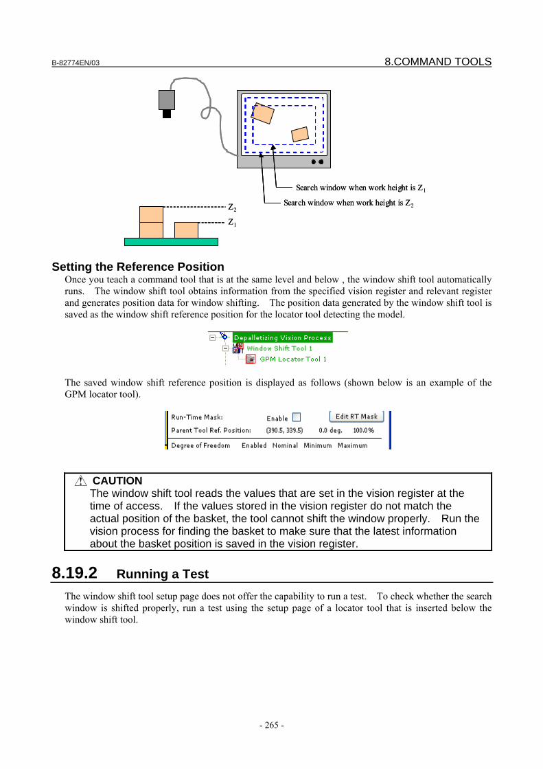
B-82774EN/03 8.COMMAND TOOLS
- 265 -
Search window when work height is Z1
Search window when work height is Z2
Z1
Z2
Search window when work height is Z1
Search window when work height is Z2
Z1
Z2
Setting the Reference Position Once you teach a command tool that is at the same level and below , the window shift tool automatically runs. The window shift tool obtains information from the specified vision register and relevant register and generates position data for window shifting. The position data generated by the window shift tool is saved as the window shift reference position for the locator tool detecting the model.
The saved window shift reference position is displayed as follows (shown below is an example of the GPM locator tool).
CAUTION The window shift tool reads the values that are set in the vision register at the
time of access. If the values stored in the vision register do not match the actual position of the basket, the tool cannot shift the window properly. Run the vision process for finding the basket to make sure that the latest information about the basket position is saved in the vision register.
8.19.2 Running a Test The window shift tool setup page does not offer the capability to run a test. To check whether the search window is shifted properly, run a test using the setup page of a locator tool that is inserted below the window shift tool.
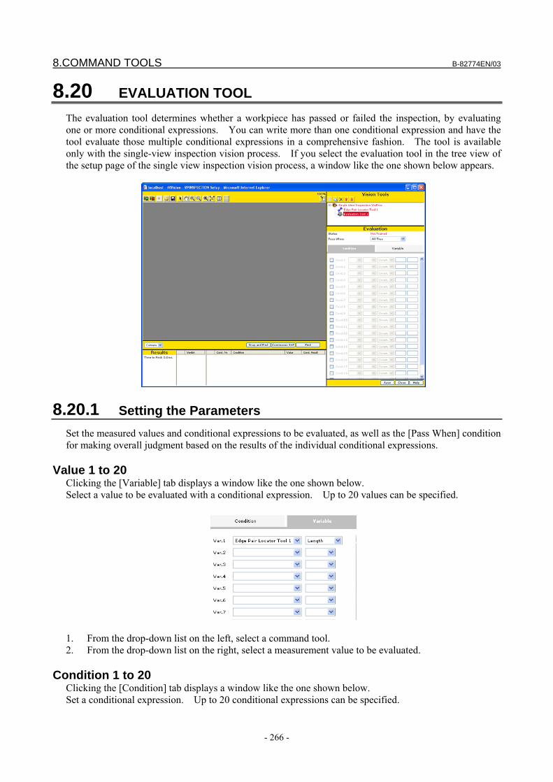
8.COMMAND TOOLS B-82774EN/03
- 266 -
8.20 EVALUATION TOOL The evaluation tool determines whether a workpiece has passed or failed the inspection, by evaluating one or more conditional expressions. You can write more than one conditional expression and have the tool evaluate those multiple conditional expressions in a comprehensive fashion. The tool is available only with the single-view inspection vision process. If you select the evaluation tool in the tree view of the setup page of the single view inspection vision process, a window like the one shown below appears.
8.20.1 Setting the Parameters Set the measured values and conditional expressions to be evaluated, as well as the [Pass When] condition for making overall judgment based on the results of the individual conditional expressions.
Value 1 to 20 Clicking the [Variable] tab displays a window like the one shown below. Select a value to be evaluated with a conditional expression. Up to 20 values can be specified.
1. From the drop-down list on the left, select a command tool. 2. From the drop-down list on the right, select a measurement value to be evaluated.
Condition 1 to 20 Clicking the [Condition] tab displays a window like the one shown below. Set a conditional expression. Up to 20 conditional expressions can be specified.
B-82774EN/03 8.COMMAND TOOLS
- 267 -
1. Enable the condition by clicking the check box. 2. From the leftmost drop-down list, select the value to be evaluated, from the following:
- Variable 1 to Variable 20 - Result of a conditional expression preceding this conditional expression
3. From the second drop-down list, select the logical expression to be used for evaluation. The available items are described later.
4. From the third drop-down list, select the value to be compared for evaluation, from the following: - Const - Variable 1 to Variable 20 - Result of a conditional expression preceding this conditional expression
5. If you select [Const] in step 4, enter a constant value in the text box on the right side.
Logical expression for evaluation As a logical expression to be specified in a conditional expression, one of the following can be selected. The available options differ depending on the type of evaluation. =
The expression is "true" if the evaluation target value is equal to the comparison value; otherwise, it is "false".
>
The expression is "true" if the evaluation target value is larger than the comparison value; otherwise, it is "false".
>=
The expression is "true" if the evaluation target value is larger than or equal to the comparison value; otherwise, it is "false".
<
The expression is "true" if the evaluation target value is smaller than the comparison value; otherwise, it is "false".
<=
The expression is "true" if the evaluation target value is smaller than or equal to the comparison value; otherwise, it is "false".
<>
The expression is "true" if the evaluation target value is not equal to the comparison value; otherwise, it is "false".
IN
The expression is "true" if the evaluation target value is within the range defined by two comparison values; otherwise, it is "false".
8.COMMAND TOOLS B-82774EN/03
- 268 -
OUT The expression is "true" if the evaluation target value is outside the range defined by two comparison values; otherwise, it is "false".
AND
The expression is "true" if both the evaluation target value and the comparison value are "true"; otherwise, it is "false".
OR
The expression is "true" if either the evaluation target value or the comparison value is "true"; otherwise, it is "false".
XOR
The expression is "true" if both the evaluation target value and the comparison value are "true" or "false"; otherwise, it is "false".
Pass When
Set a condition for making overall judgment as to whether the workpiece has passed or failed the inspection, based on the evaluation results of the individual conditional expressions.
Select one of the following: All conditions are true
The workpiece is judged to have "passed" if all the specified conditional expressions are "true" or to have "failed" if any of the specified conditional expressions are "false". [Undetermined] is displayed if there are no “false” conditions and there is at least one condition that cannot be evaluated. Typically a condition cannot be evaluated if the locator tool does not find a workpiece.
At least one condition is true
The workpiece is judged to have "passed" if any of the specified conditional expressions is "true" or to have "failed" if all the specified conditional expressions are "false". [Undetermined] is displayed if there are no “true” conditions and there is at least one condition that cannot be evaluated. Typically a condition cannot be evaluated if the locator tool does not find a workpiece.
All conditions are false
The workpiece is judged to have "passed" if all the specified conditional expressions are "false" or to have "failed" if any of the specified conditional expressions is "true". [Undetermined] is displayed if there are no “true” conditions and there is at least one condition that cannot be evaluated. Typically a condition cannot be evaluated if the locator tool does not find a workpiece.
At least one condition is false
The workpiece is judged to have "passed" if any of the specified conditional expressions is "false" or to have "failed" if all the specified conditional expressions are "true". [Undetermined] is displayed if there are no “false” conditions and there is at least one condition that cannot be evaluated. Typically a condition cannot be evaluated if the locator tool does not find a workpiece.
Last Condition True
The workpiece is judged to have "passed" if the last expression of the specified conditional expressions is "true" or to have "failed" if that expression is "false". [Undetermined] is displayed if the conditional expression cannot be evaluated.

B-82774EN/03 8.COMMAND TOOLS
- 269 -
8.20.2 Running a Test Run a test to see if the tool can perform evaluation properly.
Snap and Find button The tool snaps an image from the camera and runs a test.
Continuous S+F button The tool repeats the Snap and Find operation.
Find button The tool only performs the measurement without snapping an image from the camera.
Time to Find The time the evaluation took is displayed in milliseconds. This only represents the time it took to perform the logical operation and does not include the time it took to snap and process the image.
Verdict The overall evaluation result of the evaluation tool is displayed.
Found Result Table The number of each conditional expression evaluated and the associated evaluation logical expression, evaluation target value, comparison value, and evaluation result are displayed. Cond. No
Number of the conditional expression. Condition
Conditional expression that is set. Value
Evaluation target value evaluated with the conditional expression. Cond. Result
Evaluation result of the conditional expression.

8.COMMAND TOOLS B-82774EN/03
- 270 -
8.21 3DL CYLINDER TOOL The 3DL cylinder tool measures the surface of a cylinder workpiece, like the one shown below, using a 3D laser sensor, in order to estimate the central axis of the workpiece.
If you select [3DL Cylinder Command Tool] in the tree view, a window like the one shown below appears.
8.21.1 Setting the Measurement Area Set the area subject to laser measurement, as follows.
CAUTION If the GPM locator tool or curved surface locator tool resides in the same
program, teach the GPM locator tool or curved surface locator tool before setting this measurement area. If the model origin of the GPM locator tool or curved surface locator tool is changed or the model is re-taught, the measurement area of the cylinder measurement tool needs to be set again.
1. Click the button (green) to display the live image of the camera. 2. Click the button to turn on the laser. 3. Jog the robot so that the cylinder to be measured is at the center of the image.
You can make positioning easier to do by clicking the button, which displays the center line of the window.
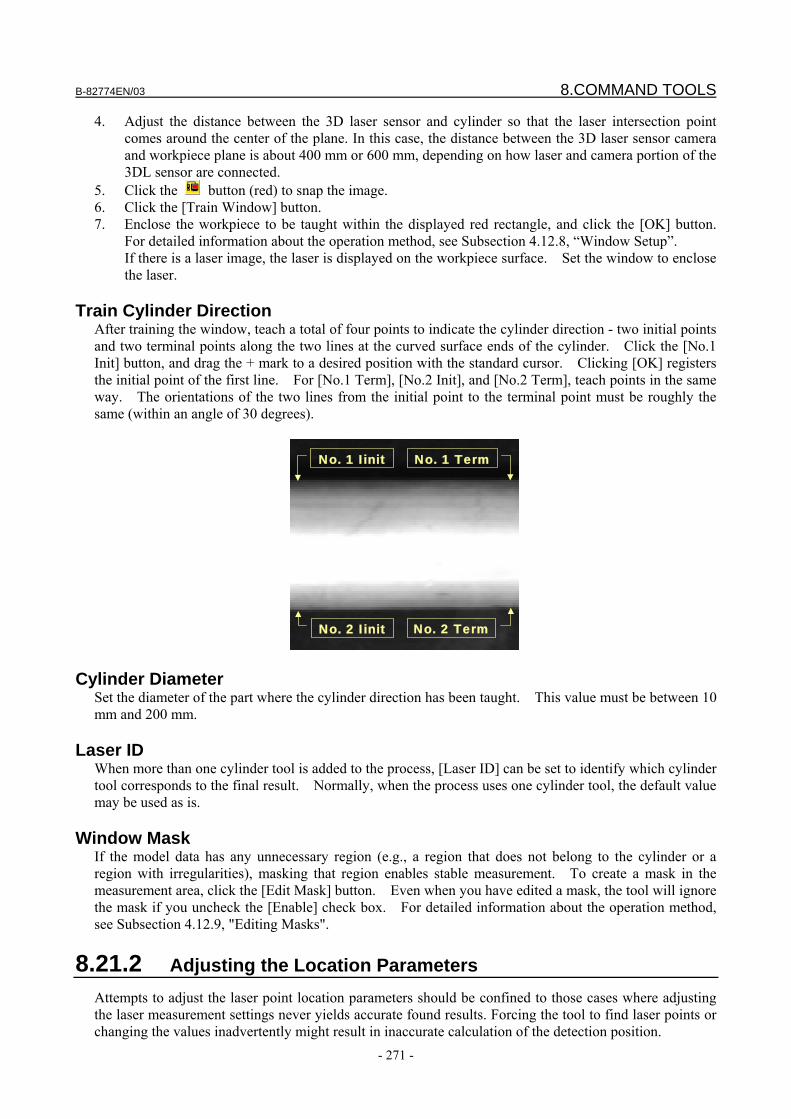
B-82774EN/03 8.COMMAND TOOLS
- 271 -
4. Adjust the distance between the 3D laser sensor and cylinder so that the laser intersection point comes around the center of the plane. In this case, the distance between the 3D laser sensor camera and workpiece plane is about 400 mm or 600 mm, depending on how laser and camera portion of the 3DL sensor are connected.
5. Click the button (red) to snap the image. 6. Click the [Train Window] button. 7. Enclose the workpiece to be taught within the displayed red rectangle, and click the [OK] button.
For detailed information about the operation method, see Subsection 4.12.8, “Window Setup”. If there is a laser image, the laser is displayed on the workpiece surface. Set the window to enclose the laser.
Train Cylinder Direction
After training the window, teach a total of four points to indicate the cylinder direction - two initial points and two terminal points along the two lines at the curved surface ends of the cylinder. Click the [No.1 Init] button, and drag the + mark to a desired position with the standard cursor. Clicking [OK] registers the initial point of the first line. For [No.1 Term], [No.2 Init], and [No.2 Term], teach points in the same way. The orientations of the two lines from the initial point to the terminal point must be roughly the same (within an angle of 30 degrees).
No. 1 Iinit No. 1 Term
No. 2 Iinit No. 2 Term
No. 1 Iinit No. 1 Term
No. 2 Iinit No. 2 Term
Cylinder Diameter
Set the diameter of the part where the cylinder direction has been taught. This value must be between 10 mm and 200 mm.
Laser ID When more than one cylinder tool is added to the process, [Laser ID] can be set to identify which cylinder tool corresponds to the final result. Normally, when the process uses one cylinder tool, the default value may be used as is.
Window Mask If the model data has any unnecessary region (e.g., a region that does not belong to the cylinder or a region with irregularities), masking that region enables stable measurement. To create a mask in the measurement area, click the [Edit Mask] button. Even when you have edited a mask, the tool will ignore the mask if you uncheck the [Enable] check box. For detailed information about the operation method, see Subsection 4.12.9, "Editing Masks".
8.21.2 Adjusting the Location Parameters Attempts to adjust the laser point location parameters should be confined to those cases where adjusting the laser measurement settings never yields accurate found results. Forcing the tool to find laser points or changing the values inadvertently might result in inaccurate calculation of the detection position.

8.COMMAND TOOLS B-82774EN/03
- 272 -
CAUTION
Before changing the location parameters, check that the laser measurement exposure time in the vision process has been adjusted so that an image is captured adequately.
Min. Num Laser Points 1
If the min. number laser points 1 found in the measurement area, excluding the mask area, is below this threshold, the measurement result is invalid. Set this to a value between 2 and 480.
Min. Num Laser Points 2 If the min. number laser points 2 found in the measurement area, excluding the mask area, is below this threshold, the measurement result is invalid. Set this to a value between 2 and 480.
Laser 1 Contrast This is the threshold for finding points of the laser 1 applied to the measurement area, excluding the mask area. Set this to a value between 0 and 255.
Laser 2 Contrast This is the threshold for finding points of the laser 1 applied to the measurement area, excluding the mask area. Set this to a value between 0 and 255.
Max Fit Error When a cylinder surface is formed by laser points applied to the measurement area, excluding the mask area, each of these points is regarded as valid if the point's error from the cylinder surface is below this threshold. Set this to a value between 0 and 10 mm. The maximum value may change depending on the cylinder diameter.
Laser Plotting Mode Select how the laser label is to be displayed on the image when the process is run. Plot CW mode
The laser label is displayed clockwise. Plot CCW mode
The laser label is displayed counterclockwise. Plot nothing
The laser label is not displayed.
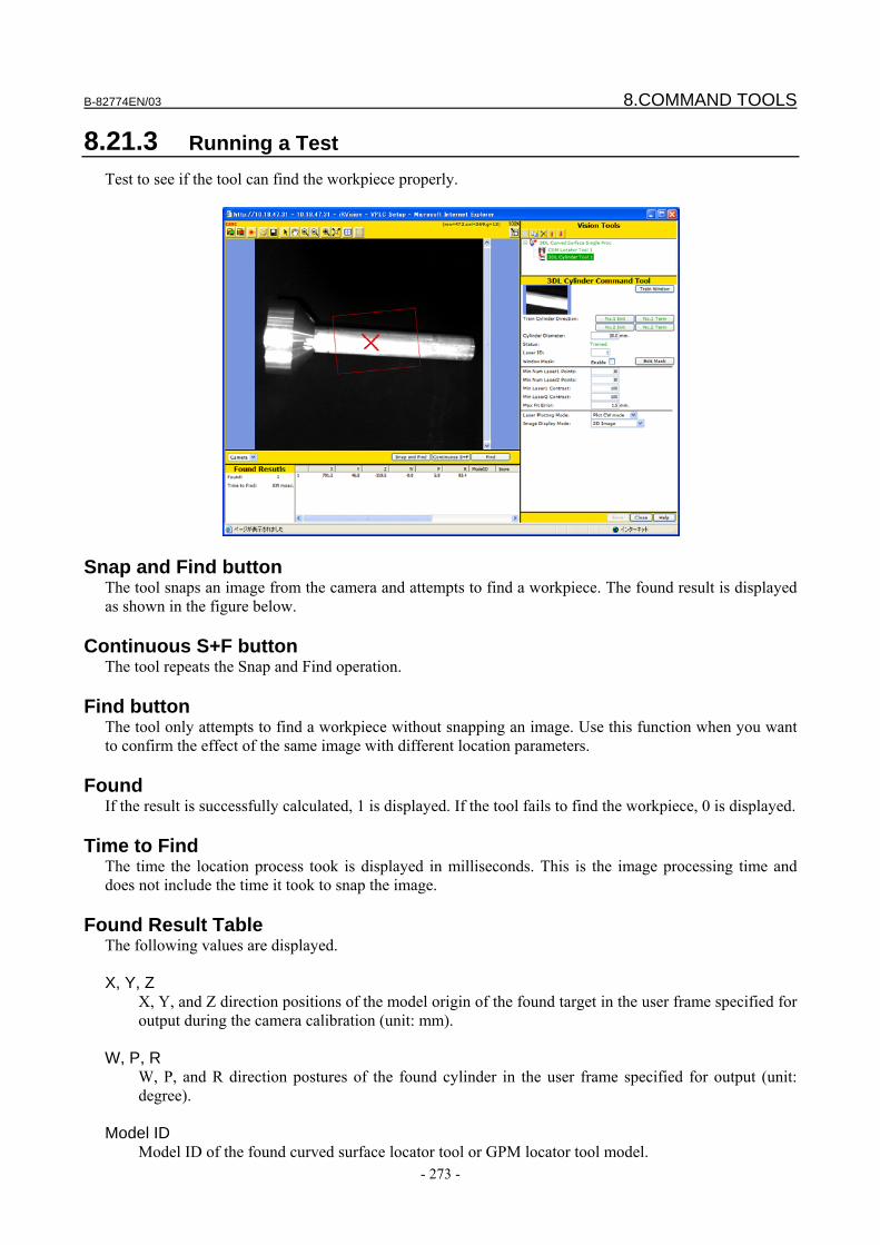
B-82774EN/03 8.COMMAND TOOLS
- 273 -
8.21.3 Running a Test Test to see if the tool can find the workpiece properly.
Snap and Find button The tool snaps an image from the camera and attempts to find a workpiece. The found result is displayed as shown in the figure below.
Continuous S+F button The tool repeats the Snap and Find operation.
Find button The tool only attempts to find a workpiece without snapping an image. Use this function when you want to confirm the effect of the same image with different location parameters.
Found If the result is successfully calculated, 1 is displayed. If the tool fails to find the workpiece, 0 is displayed.
Time to Find The time the location process took is displayed in milliseconds. This is the image processing time and does not include the time it took to snap the image.
Found Result Table The following values are displayed. X, Y, Z X, Y, and Z direction positions of the model origin of the found target in the user frame specified for
output during the camera calibration (unit: mm). W, P, R W, P, and R direction postures of the found cylinder in the user frame specified for output (unit:
degree). Model ID Model ID of the found curved surface locator tool or GPM locator tool model.
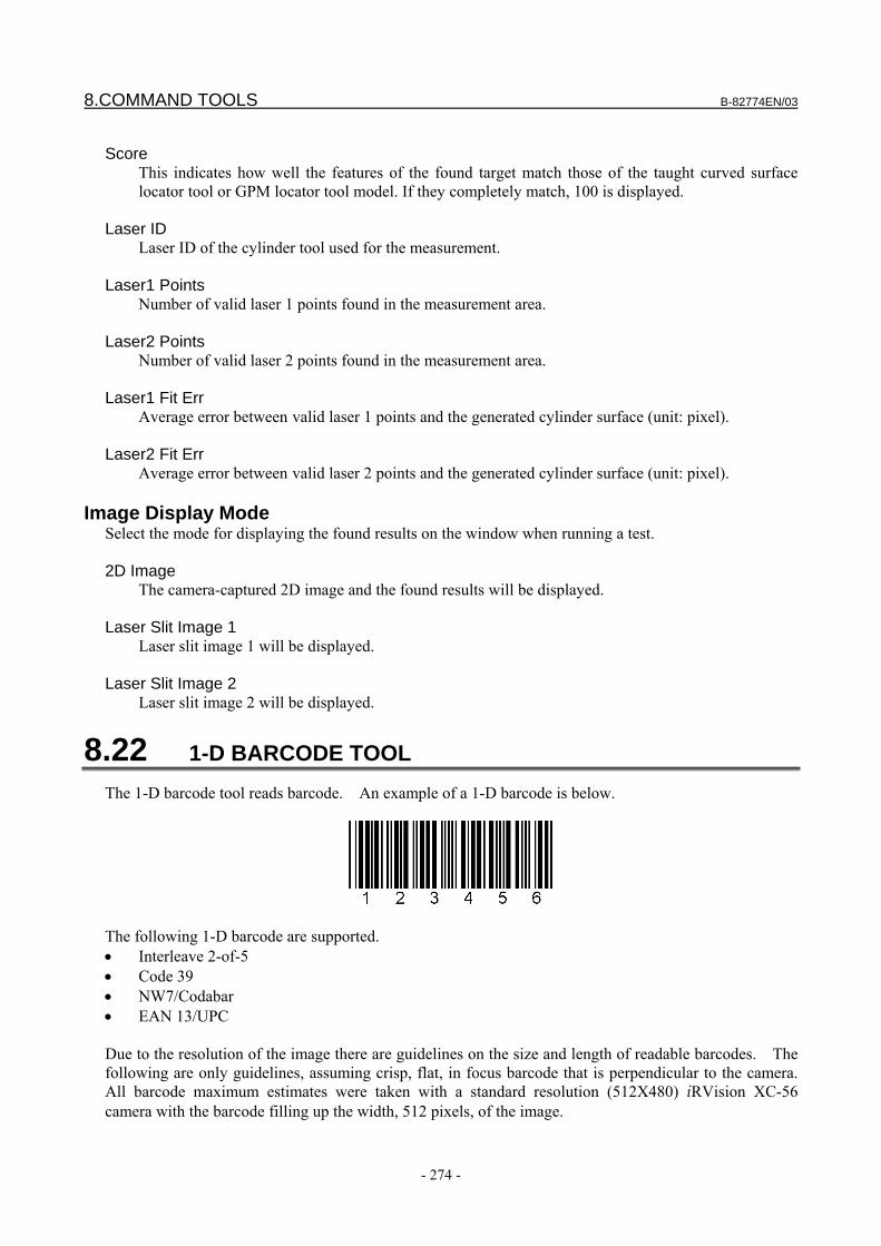
8.COMMAND TOOLS B-82774EN/03
- 274 -
Score This indicates how well the features of the found target match those of the taught curved surface
locator tool or GPM locator tool model. If they completely match, 100 is displayed. Laser ID Laser ID of the cylinder tool used for the measurement. Laser1 Points Number of valid laser 1 points found in the measurement area. Laser2 Points Number of valid laser 2 points found in the measurement area. Laser1 Fit Err Average error between valid laser 1 points and the generated cylinder surface (unit: pixel). Laser2 Fit Err Average error between valid laser 2 points and the generated cylinder surface (unit: pixel).
Image Display Mode Select the mode for displaying the found results on the window when running a test. 2D Image The camera-captured 2D image and the found results will be displayed. Laser Slit Image 1
Laser slit image 1 will be displayed. Laser Slit Image 2
Laser slit image 2 will be displayed.
8.22 1-D BARCODE TOOL The 1-D barcode tool reads barcode. An example of a 1-D barcode is below.
The following 1-D barcode are supported. • Interleave 2-of-5 • Code 39 • NW7/Codabar • EAN 13/UPC Due to the resolution of the image there are guidelines on the size and length of readable barcodes. The following are only guidelines, assuming crisp, flat, in focus barcode that is perpendicular to the camera. All barcode maximum estimates were taken with a standard resolution (512X480) iRVision XC-56 camera with the barcode filling up the width, 512 pixels, of the image.
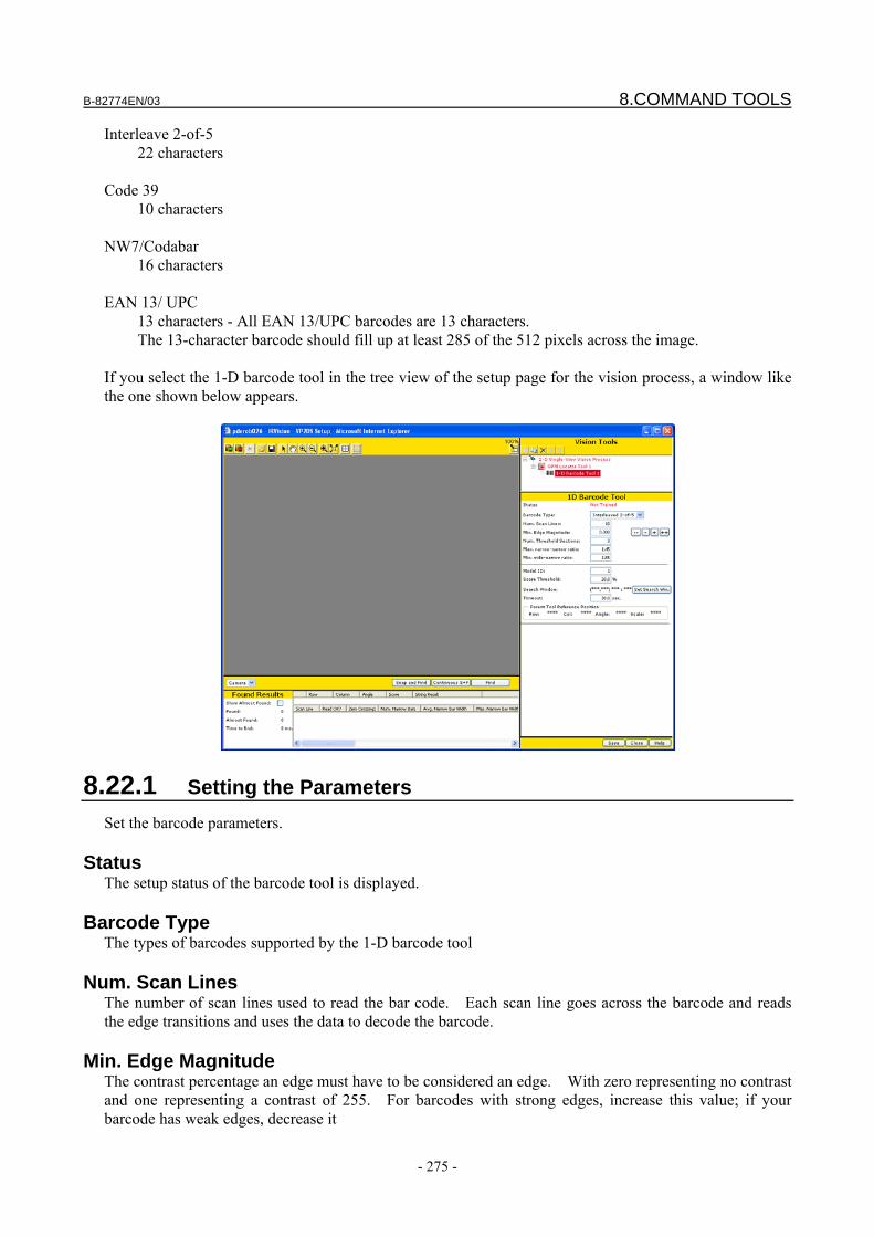
B-82774EN/03 8.COMMAND TOOLS
- 275 -
Interleave 2-of-5 22 characters
Code 39
10 characters NW7/Codabar
16 characters EAN 13/ UPC
13 characters - All EAN 13/UPC barcodes are 13 characters. The 13-character barcode should fill up at least 285 of the 512 pixels across the image.
If you select the 1-D barcode tool in the tree view of the setup page for the vision process, a window like the one shown below appears.
8.22.1 Setting the Parameters Set the barcode parameters.
Status The setup status of the barcode tool is displayed.
Barcode Type The types of barcodes supported by the 1-D barcode tool
Num. Scan Lines The number of scan lines used to read the bar code. Each scan line goes across the barcode and reads the edge transitions and uses the data to decode the barcode.
Min. Edge Magnitude The contrast percentage an edge must have to be considered an edge. With zero representing no contrast and one representing a contrast of 255. For barcodes with strong edges, increase this value; if your barcode has weak edges, decrease it
8.COMMAND TOOLS B-82774EN/03
- 276 -
Num. Threshold Sections The number of sections into which the barcode algorithm will divide the barcode image for edge detection. Increase this value if you have uneven lighting across your barcode.
Max Narrow-Narrow Ratio The maximum allowable ratio between the thinnest and the thickest narrow bar
Min Wide-Narrow Ratio The minimum allowable ratio between the thinnest wide bar and the thickest narrow bar
Code Subtype (EAN Barcode only) The subtype of an EAN Barcode. UPC is a subtype of EAN.
Start Digit (EAN Barcode only) The start digit for EAN barcodes.
8.22.2 Barcode Training Train the barcode tool.
Model ID When you have two or more taught barcodes you can assign each a unique model ID.
Score Threshold The percentage of scan lines that successfully decoded the barcode with the same result required for a find.
Search Window The window that the barcode tool searches for the specified barcode. Set the a few pixels larger than the barcode for best results.
8.22.3 Running a test Test to see if the barcode was properly found.
B-82774EN/03 8.COMMAND TOOLS
- 277 -
Snap and Find button The tool snaps an image from the camera and attempts to find a workpiece. The found result is displayed as shown in the figure below.
Continuous S+F button The tool repeats the Snap and Find operation.
Find button The tool only attempts to find a workpiece without snapping an image. Use this function when you want to confirm the effect of the same image with different location parameters.
Found If the result is successfully calculated, 1 is displayed. If the tool fails to find the workpiece, 0 is displayed.
Time to Find The time the location process took is displayed in milliseconds. This is the image processing time and does not include the time it took to snap the image.
Found Result Table The following values are displayed. Row, Column
The found position of the origin of the barcode (unit: pixel). Angle
The found angle of the barcode (unit: degrees). Score
The percentage of scan lines that successfully decoded the barcode. String Result
The string decoded in the barcode.
8.COMMAND TOOLS B-82774EN/03
- 278 -
Scan Line Details This table lists the specific barcode details of each scan line. If a scan line fails you can use this information to decipher why it failed.
8.22.4 Uses of Barcode Tool The barcode tool can be a child of any locator tool or a stand-alone parent in an error proof vision process. Once the barcode tool has been executed the found string may be used in the following ways: String Output Tool
The string value can be put into a String Register for use in the teach pendant program. For details on the String Output Tool see the Sting Output Tool section in this manual.
Measurement of Error Proofing In the error proofing vision process the numeric strings can be evaluated as well as the length of alphanumeric strings.
8.23 STRING OUTPUT TOOL The String Output Tool can be utilized to output a string from a barcode tool to the vision register where is can be extracted and used in the teach pendant program. Only one string can be stored per vision register. If multiple string output tools successfully run in a vision process then only the last string will be available in the vision register. If you select the string output tool in the tree view of the setup page for the vision process, a page like the one shown below appears.
8.23.1 Setting the Parameters
Value A Barcode tools and their strings are the only choices to select.
B-82774EN/03 8.COMMAND TOOLS
- 279 -
8.23.2 Running a Test Test to see if the tool can output a string value properly.
Snap and Find button The tool snaps an image from the camera and attempts to find a workpiece.
Continuous S+F button The tool repeats the Snap and Find operation.
Find button The tool only attempts to perform the measurement without snapping an image.
Found The number of found workpieces is displayed.
Time to Find The time the location process took is displayed in milliseconds. This is the image processing time and does not include the time it took to snap the image.
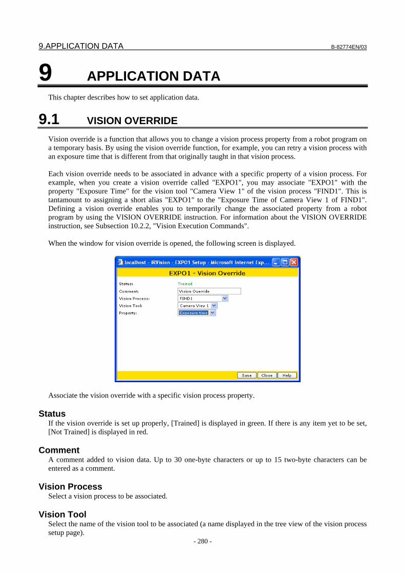
9.APPLICATION DATA B-82774EN/03
- 280 -
9 APPLICATION DATA This chapter describes how to set application data.
9.1 VISION OVERRIDE Vision override is a function that allows you to change a vision process property from a robot program on a temporary basis. By using the vision override function, for example, you can retry a vision process with an exposure time that is different from that originally taught in that vision process. Each vision override needs to be associated in advance with a specific property of a vision process. For example, when you create a vision override called "EXPO1", you may associate "EXPO1" with the property "Exposure Time" for the vision tool "Camera View 1" of the vision process "FIND1". This is tantamount to assigning a short alias "EXPO1" to the "Exposure Time of Camera View 1 of FIND1". Defining a vision override enables you to temporarily change the associated property from a robot program by using the VISION OVERRIDE instruction. For information about the VISION OVERRIDE instruction, see Subsection 10.2.2, "Vision Execution Commands". When the window for vision override is opened, the following screen is displayed.
Associate the vision override with a specific vision process property.
Status If the vision override is set up properly, [Trained] is displayed in green. If there is any item yet to be set, [Not Trained] is displayed in red.
Comment A comment added to vision data. Up to 30 one-byte characters or up to 15 two-byte characters can be entered as a comment.
Vision Process Select a vision process to be associated.
Vision Tool Select the name of the vision tool to be associated (a name displayed in the tree view of the vision process setup page).
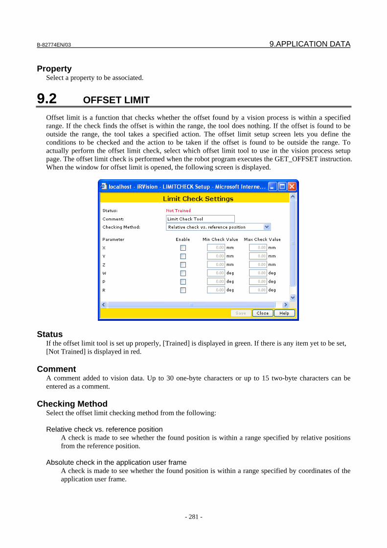
B-82774EN/03 9.APPLICATION DATA
- 281 -
Property
Select a property to be associated.
9.2 OFFSET LIMIT Offset limit is a function that checks whether the offset found by a vision process is within a specified range. If the check finds the offset is within the range, the tool does nothing. If the offset is found to be outside the range, the tool takes a specified action. The offset limit setup screen lets you define the conditions to be checked and the action to be taken if the offset is found to be outside the range. To actually perform the offset limit check, select which offset limit tool to use in the vision process setup page. The offset limit check is performed when the robot program executes the GET_OFFSET instruction. When the window for offset limit is opened, the following screen is displayed.
Status If the offset limit tool is set up properly, [Trained] is displayed in green. If there is any item yet to be set, [Not Trained] is displayed in red.
Comment A comment added to vision data. Up to 30 one-byte characters or up to 15 two-byte characters can be entered as a comment.
Checking Method Select the offset limit checking method from the following: Relative check vs. reference position
A check is made to see whether the found position is within a range specified by relative positions from the reference position.
Absolute check in the application user frame
A check is made to see whether the found position is within a range specified by coordinates of the application user frame.
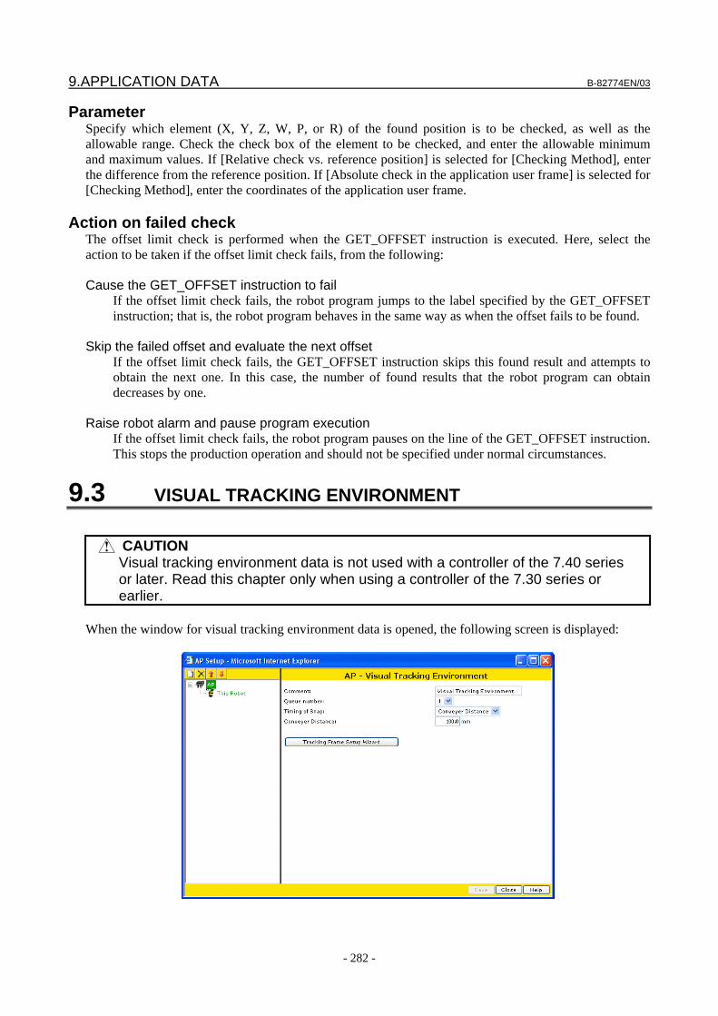
9.APPLICATION DATA B-82774EN/03
- 282 -
Parameter Specify which element (X, Y, Z, W, P, or R) of the found position is to be checked, as well as the allowable range. Check the check box of the element to be checked, and enter the allowable minimum and maximum values. If [Relative check vs. reference position] is selected for [Checking Method], enter the difference from the reference position. If [Absolute check in the application user frame] is selected for [Checking Method], enter the coordinates of the application user frame.
Action on failed check The offset limit check is performed when the GET_OFFSET instruction is executed. Here, select the action to be taken if the offset limit check fails, from the following: Cause the GET_OFFSET instruction to fail
If the offset limit check fails, the robot program jumps to the label specified by the GET_OFFSET instruction; that is, the robot program behaves in the same way as when the offset fails to be found.
Skip the failed offset and evaluate the next offset
If the offset limit check fails, the GET_OFFSET instruction skips this found result and attempts to obtain the next one. In this case, the number of found results that the robot program can obtain decreases by one.
Raise robot alarm and pause program execution
If the offset limit check fails, the robot program pauses on the line of the GET_OFFSET instruction. This stops the production operation and should not be specified under normal circumstances.
9.3 VISUAL TRACKING ENVIRONMENT
CAUTION Visual tracking environment data is not used with a controller of the 7.40 series
or later. Read this chapter only when using a controller of the 7.30 series or earlier.
When the window for visual tracking environment data is opened, the following screen is displayed:
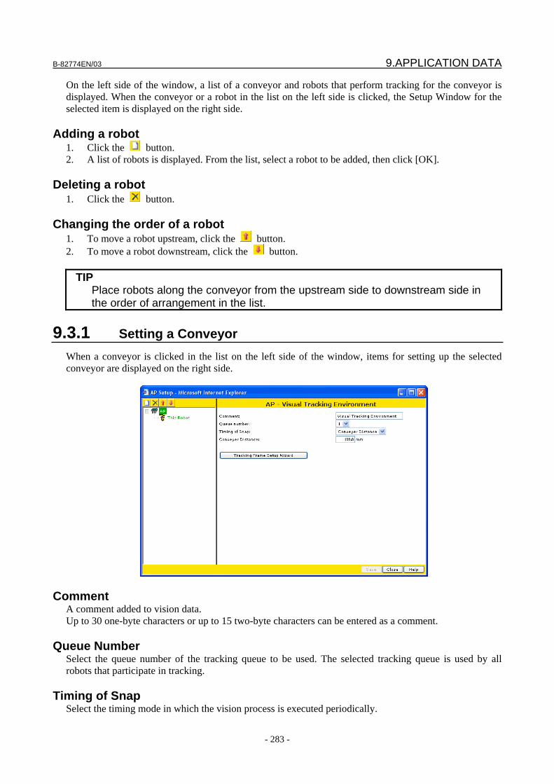
B-82774EN/03 9.APPLICATION DATA
- 283 -
On the left side of the window, a list of a conveyor and robots that perform tracking for the conveyor is displayed. When the conveyor or a robot in the list on the left side is clicked, the Setup Window for the selected item is displayed on the right side.
Adding a robot 1. Click the button. 2. A list of robots is displayed. From the list, select a robot to be added, then click [OK].
Deleting a robot 1. Click the button.
Changing the order of a robot 1. To move a robot upstream, click the button. 2. To move a robot downstream, click the button.
TIP Place robots along the conveyor from the upstream side to downstream side in
the order of arrangement in the list.
9.3.1 Setting a Conveyor When a conveyor is clicked in the list on the left side of the window, items for setting up the selected conveyor are displayed on the right side.
Comment A comment added to vision data. Up to 30 one-byte characters or up to 15 two-byte characters can be entered as a comment.
Queue Number Select the queue number of the tracking queue to be used. The selected tracking queue is used by all robots that participate in tracking.
Timing of Snap Select the timing mode in which the vision process is executed periodically.
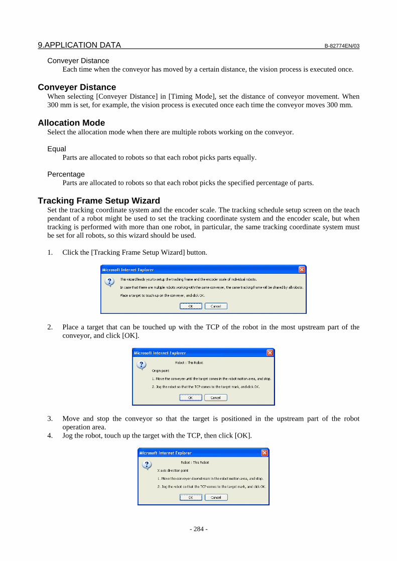
9.APPLICATION DATA B-82774EN/03
- 284 -
Conveyer Distance Each time when the conveyor has moved by a certain distance, the vision process is executed once.
Conveyer Distance
When selecting [Conveyer Distance] in [Timing Mode], set the distance of conveyor movement. When 300 mm is set, for example, the vision process is executed once each time the conveyor moves 300 mm.
Allocation Mode Select the allocation mode when there are multiple robots working on the conveyor. Equal
Parts are allocated to robots so that each robot picks parts equally. Percentage
Parts are allocated to robots so that each robot picks the specified percentage of parts.
Tracking Frame Setup Wizard Set the tracking coordinate system and the encoder scale. The tracking schedule setup screen on the teach pendant of a robot might be used to set the tracking coordinate system and the encoder scale, but when tracking is performed with more than one robot, in particular, the same tracking coordinate system must be set for all robots, so this wizard should be used. 1. Click the [Tracking Frame Setup Wizard] button.
2. Place a target that can be touched up with the TCP of the robot in the most upstream part of the
conveyor, and click [OK].
3. Move and stop the conveyor so that the target is positioned in the upstream part of the robot
operation area. 4. Jog the robot, touch up the target with the TCP, then click [OK].
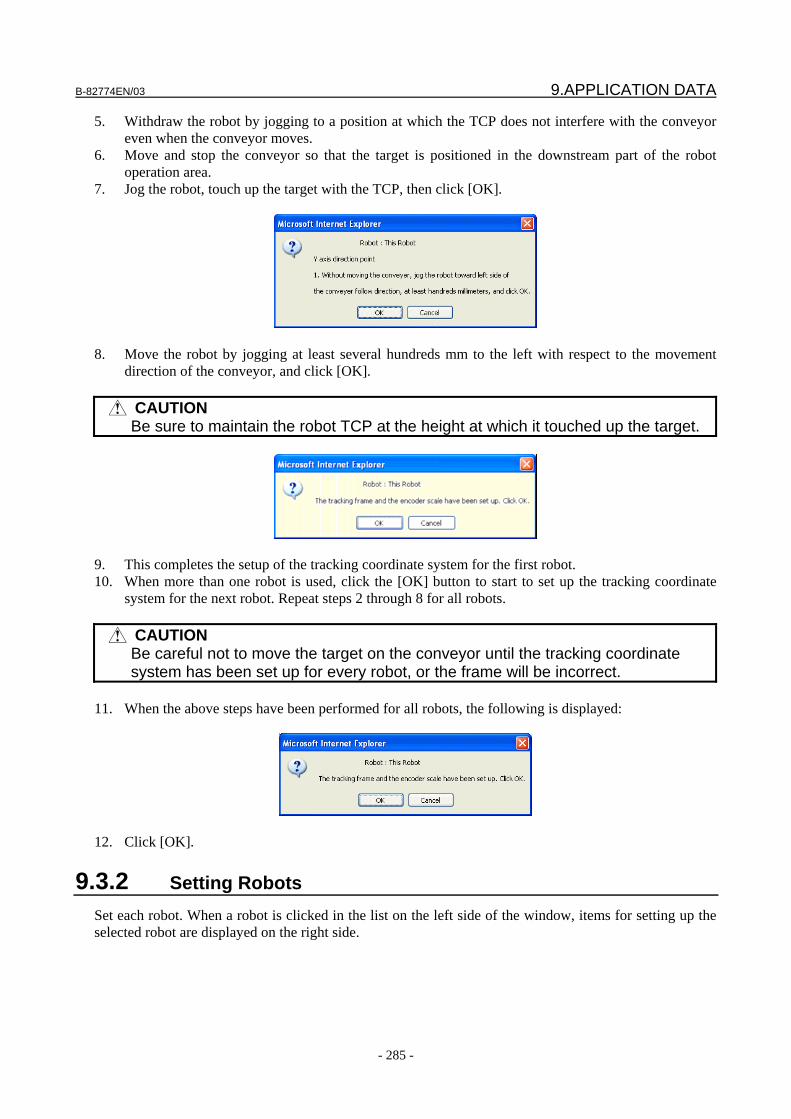
B-82774EN/03 9.APPLICATION DATA
- 285 -
5. Withdraw the robot by jogging to a position at which the TCP does not interfere with the conveyor even when the conveyor moves.
6. Move and stop the conveyor so that the target is positioned in the downstream part of the robot operation area.
7. Jog the robot, touch up the target with the TCP, then click [OK].
8. Move the robot by jogging at least several hundreds mm to the left with respect to the movement
direction of the conveyor, and click [OK].
CAUTION Be sure to maintain the robot TCP at the height at which it touched up the target.
9. This completes the setup of the tracking coordinate system for the first robot. 10. When more than one robot is used, click the [OK] button to start to set up the tracking coordinate
system for the next robot. Repeat steps 2 through 8 for all robots.
CAUTION Be careful not to move the target on the conveyor until the tracking coordinate
system has been set up for every robot, or the frame will be incorrect. 11. When the above steps have been performed for all robots, the following is displayed:
12. Click [OK].
9.3.2 Setting Robots Set each robot. When a robot is clicked in the list on the left side of the window, items for setting up the selected robot are displayed on the right side.
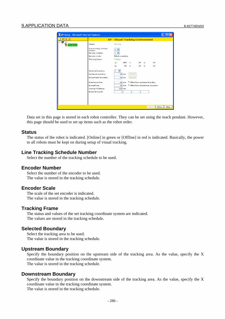
9.APPLICATION DATA B-82774EN/03
- 286 -
Data set in this page is stored in each robot controller. They can be set using the teach pendant. However, this page should be used to set up items such as the robot order.
Status The status of the robot is indicated. [Online] in green or [Offline] in red is indicated. Basically, the power to all robots must be kept on during setup of visual tracking.
Line Tracking Schedule Number Select the number of the tracking schedule to be used.
Encoder Number Select the number of the encoder to be used. The value is stored in the tracking schedule.
Encoder Scale The scale of the set encoder is indicated. The value is stored in the tracking schedule.
Tracking Frame The status and values of the set tracking coordinate system are indicated. The values are stored in the tracking schedule.
Selected Boundary Select the tracking area to be used. The value is stored in the tracking schedule.
Upstream Boundary Specify the boundary position on the upstream side of the tracking area. As the value, specify the X coordinate value in the tracking coordinate system. The value is stored in the tracking schedule.
Downstream Boundary Specify the boundary position on the downstream side of the tracking area. As the value, specify the X coordinate value in the tracking coordinate system. The value is stored in the tracking schedule.

B-82774EN/03 9.APPLICATION DATA
- 287 -
Distribution Line Set an offset value from the boundary on the upstream side of the tracking area. Typically, this should be a small negative value. This allows the workpiece to be passed to the robot before the workpiece enters the tracking area. Therefore, the robot will pick up the workpiece after waiting for a time equal to the value of the offset.
Discard Line Set an offset value from the boundary on the downstream side of the tracking area. When a conveyed workpiece has passed across this line, the robot determines that it can no longer catch up with the workpiece. Typically, set this to a small negative value.
Overlap Tolerance Set a threshold value by which whether found workpieces are the same workpiece or not is determined when the same workpiece is found more than once.
Gripper Specify if the gripper of the robot is single-pick or multi-pick.
Gripper Index Register When the gripper is multi-pick, specify the register number in which the robot program sets the gripper number for the next part.
Model IDs to Pick Specify the model ID of workpieces the robot picks up. If a workpiece that does not belong to the specified model ID is conveyed, the robot does not pick up the workpiece. Up to four IDs can be specified for each robot. When the same model ID is specified for more than one robot, workpieces of that model are evenly distributed to these robots.
Pick Allocation Specify how many parts the robot should pick, when you select “Percentage” for “Allocation Mode” on the conveyor setup page, you can specify different percentage for each model ID.
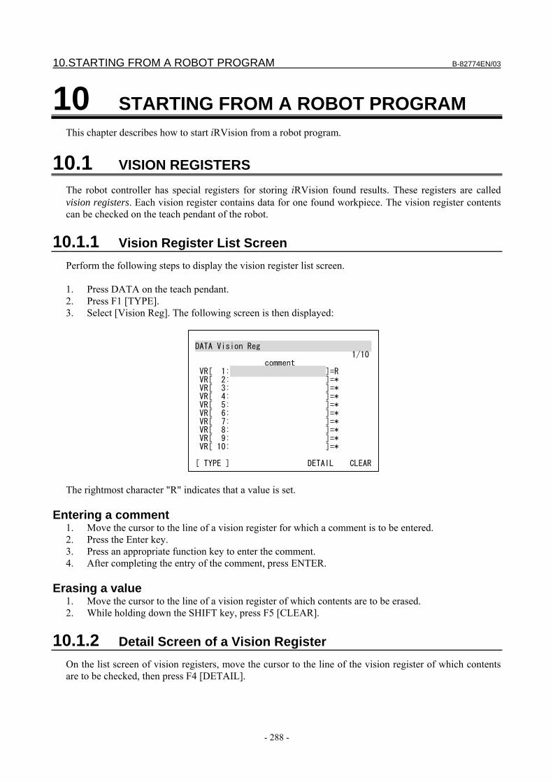
10.STARTING FROM A ROBOT PROGRAM B-82774EN/03
- 288 -
10 STARTING FROM A ROBOT PROGRAM This chapter describes how to start iRVision from a robot program.
10.1 VISION REGISTERS The robot controller has special registers for storing iRVision found results. These registers are called vision registers. Each vision register contains data for one found workpiece. The vision register contents can be checked on the teach pendant of the robot.
10.1.1 Vision Register List Screen Perform the following steps to display the vision register list screen. 1. Press DATA on the teach pendant. 2. Press F1 [TYPE]. 3. Select [Vision Reg]. The following screen is then displayed:
DATA Vision Reg 1/10 comment VR[ 1: ]=R VR[ 2: ]=* VR[ 3: ]=* VR[ 4: ]=* VR[ 5: ]=* VR[ 6: ]=* VR[ 7: ]=* VR[ 8: ]=* VR[ 9: ]=* VR[ 10: ]=* [ TYPE ] DETAIL CLEAR
The rightmost character "R" indicates that a value is set.
Entering a comment 1. Move the cursor to the line of a vision register for which a comment is to be entered. 2. Press the Enter key. 3. Press an appropriate function key to enter the comment. 4. After completing the entry of the comment, press ENTER.
Erasing a value 1. Move the cursor to the line of a vision register of which contents are to be erased. 2. While holding down the SHIFT key, press F5 [CLEAR].
10.1.2 Detail Screen of a Vision Register On the list screen of vision registers, move the cursor to the line of the vision register of which contents are to be checked, then press F4 [DETAIL].
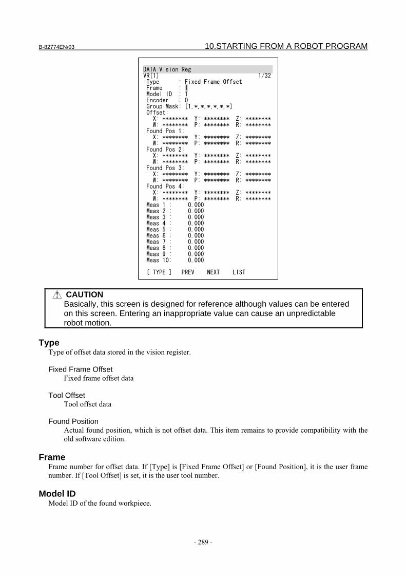
B-82774EN/03 10.STARTING FROM A ROBOT PROGRAM
- 289 -
DATA Vision Reg VR[1] 1/32 Type : Fixed Frame Offset Frame : 1 Model ID : 1 Encoder : 0 Group Mask: [1,*,*,*,*,*,*] Offset: X: ******** Y: ******** Z: ******** W: ******** P: ******** R: ******** Found Pos 1: X: ******** Y: ******** Z: ******** W: ******** P: ******** R: ******** Found Pos 2: X: ******** Y: ******** Z: ******** W: ******** P: ******** R: ******** Found Pos 3: X: ******** Y: ******** Z: ******** W: ******** P: ******** R: ******** Found Pos 4: X: ******** Y: ******** Z: ******** W: ******** P: ******** R: ******** Meas 1 : 0.000 Meas 2 : 0.000 Meas 3 : 0.000 Meas 4 : 0.000 Meas 5 : 0.000 Meas 6 : 0.000 Meas 7 : 0.000 Meas 8 : 0.000 Meas 9 : 0.000 Meas 10: 0.000 [ TYPE ] PREV NEXT LIST
CAUTION Basically, this screen is designed for reference although values can be entered
on this screen. Entering an inappropriate value can cause an unpredictable robot motion.
Type
Type of offset data stored in the vision register. Fixed Frame Offset
Fixed frame offset data Tool Offset
Tool offset data Found Position
Actual found position, which is not offset data. This item remains to provide compatibility with the old software edition.
Frame
Frame number for offset data. If [Type] is [Fixed Frame Offset] or [Found Position], it is the user frame number. If [Tool Offset] is set, it is the user tool number.
Model ID Model ID of the found workpiece.
10.STARTING FROM A ROBOT PROGRAM B-82774EN/03
- 290 -
Encoder Count of the encoder that triggers visual tracking for a found workpiece. This item is not used for purposes other than visual tracking.
Group Mask Group mask of offset data.
Offset Offset data represented in the XYZWPR format.
Found Pos Actual position of each camera view.
Meas Measurement value of a tool such as a histogram.
Displaying the screen of previous or following vision register 1. Pressing F2 [PREV] displays the detail screen of the previous vision register. 2. Pressing F3 [NEXT] displays the detail screen of the next vision register.
Returning to the vision data list screen 1. Pressing F4 [LIST] returns the screen display to the original vision data list screen.
10.2 PROGRAM COMMANDS Program commands for iRVision are provided.
10.2.1 Vision Offset Command This command offsets the robot position by using offset data stored in a vision register.
10.2.1.1 VOFFSET VOFFSET is an optional operation command that is added to a robot motion command. Move the cursor to a position after an operation command, press F4 [CHOICE] to display a list of additional operation commands, and select VOFFSET, VR.
L P[1] 500mm/sec FINE VOFFSET,VR[a]
If the type of offset data stored in the specified vision register is [Fixed Frame Offset], a fixed frame offset is applied. If the type is [Tool Offset], a tool offset is applied. Position offset is performed properly based on the coordinate system in which iRVision calculated the offset data, regardless of the currently selected user frame/user tool and the user frame/user tool of the position data of the motion command.
10.2.2 Vision Execution Commands These commands instruct iRVision to perform processing.
B-82774EN/03 10.STARTING FROM A ROBOT PROGRAM
- 291 -
10.2.2.1 RUN_FIND This command starts a vision process. When a specified vision process has more than one camera view, location is performed for all camera views.
VISION RUN_FIND (vision-process-name)
When a vision process has multiple camera views, and location is to be performed for one of these views, add CAMERA_VIEW[] command.
VISION RUN_FIND (vision-process-name) CAMERA_VIEW[a]
In the execution of a vision location command, when the vision process has snapped an image, the next line of the program is executed, and image processing is performed in the background. This allows vision image processing and another operation such as a robot motion to be performed in parallel.
10.2.2.2 RUN_FIND SR[ ] This command works like RUN_FIND except the vision process name is stored in a String Register
10.2.2.3 GET_OFFSET This command gets a vision offset from a vision process and stores it in a specified vision register. This command is used after RUN_FIND. If image processing is not yet completed when GET_OFFSET is executed, it waits for the completion of the image processing.
VISION GET_OFFSET (vision-process-name) VR[a] JMP,LBL[b]
GET_OFFSET stores the vision offset for a workpiece in a vision register. When the vision process finds more than one workpiece, GET_OFFSET should be called repeatedly. If no workpiece is detected or no more offset data is available because of repeated execution of GET_OFFSET, it jumps to the specified label.
TIP A measurement value specified with the measurement value output tool is
written to the vision register together with offset data by this GET_OFFSET command.
It is possible for the controller without iRVision to get offset data from other controllers. This is generally used when the robots work big workpieces together. You should add the name of the robot before the name of vision process to gain offset data from other controllers.
VISION GET_OFFSET ROBOT1.VISPRO1 VR[1]
The robot name is the one you gave in the section 4.9, “Setup Robot Ring”.
10.STARTING FROM A ROBOT PROGRAM B-82774EN/03
- 292 -
CAUTION With a vision process that detects multiple small workpieces in one
measurement such as the 2-D single view vision process, the offset data obtained by a robot cannot be obtained by another robot. On the other hand, with a vision process that detects only one large workpiece at a time such as the 2-D multi-view vision process, the same offset data can be obtained by multiple robots.
10.2.2.4 GET_OFFSET SR[ ]
This command works like GET_OFFSET except the vision process name is stored in a String Register
10.2.2.5 SET_REFERENCE This command sets the reference position in a vision process. The command is used after RUN_FIND. The command has the same effect as the [Set Ref. Pos.] button in the setup window for a vision process.
VISION SET_REFERENCE (vision-process-name)
If a vision process remains open on the setup PC when SET_REFERENCE is executed for the vision process, the reference position cannot be written to the vision process, which results in CVIS-103 “The vision data file is already open for writing” alarm. Close the setup window, then re-execute the command. When the vision process finds more than one workpiece, the position of the workpiece having the highest score is set as the reference position. It is recommended that only one workpiece be placed within the camera view so that an incorrect position is not set as the reference position.
10.2.2.6 SET_REFERENCE SR[ ] This command works like SET_REFERENCE except the vision process name is stored in a String Register
10.2.2.7 CAMERA_CALIB This command performs camera calibration.
VISION CAMERA_CALIB (camera-calibration-name) (request-code)
The value specified as the request code varies depending on the type of camera calibration. Refer to the following table:
Calibration Type Request Code Grid Pattern Calibration Specify the index of the calibration plane, 1 or 2. 3D Laser Calibration Specify the index of the calibration plane, 1 or 2. Robot-Generated Grid Calibration Specify a different number for each calibration point. In the case of
robot-generated grid calibration, a robot program using this command is automatically generated. For details, see Section 11.3, “ROBOT-GENERATED GRID CALIBRATION”.
Visual Tracking Calibration Not supported Simple 2D Calibration Not supported
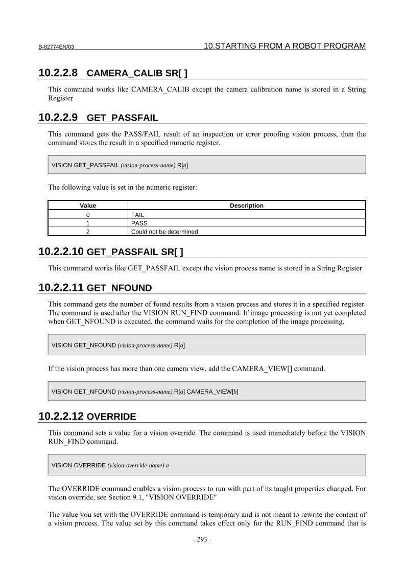
B-82774EN/03 10.STARTING FROM A ROBOT PROGRAM
- 293 -
10.2.2.8 CAMERA_CALIB SR[ ]
This command works like CAMERA_CALIB except the camera calibration name is stored in a String Register
10.2.2.9 GET_PASSFAIL This command gets the PASS/FAIL result of an inspection or error proofing vision process, then the command stores the result in a specified numeric register.
VISION GET_PASSFAIL (vision-process-name) R[a]
The following value is set in the numeric register:
Value Description 0 FAIL 1 PASS 2 Could not be determined
10.2.2.10 GET_PASSFAIL SR[ ]
This command works like GET_PASSFAIL except the vision process name is stored in a String Register
10.2.2.11 GET_NFOUND This command gets the number of found results from a vision process and stores it in a specified register. The command is used after the VISION RUN_FIND command. If image processing is not yet completed when GET_NFOUND is executed, the command waits for the completion of the image processing.
VISION GET_NFOUND (vision-process-name) R[a]
If the vision process has more than one camera view, add the CAMERA_VIEW[] command.
VISION GET_NFOUND (vision-process-name) R[a] CAMERA_VIEW[b]
10.2.2.12 OVERRIDE
This command sets a value for a vision override. The command is used immediately before the VISION RUN_FIND command.
VISION OVERRIDE (vision-override-name) a
The OVERRIDE command enables a vision process to run with part of its taught properties changed. For vision override, see Section 9.1, "VISION OVERRIDE" The value you set with the OVERRIDE command is temporary and is not meant to rewrite the content of a vision process. The value set by this command takes effect only for the RUN_FIND command that is
10.STARTING FROM A ROBOT PROGRAM B-82774EN/03
- 294 -
executed immediately after the OVERRIDE command. Once the RUN_FIND command is executed, all the values set by the OVERRIDE command (including those vision overrides associated with vision processes other than the vision process that executes location) are cleared.
10.2.3 Visual Tracking Commands Visual tracking commands are used for visual tracking
CAUTION Read this chapter only when you use V7.30P or earlier version of controller.
For V7.40P and later versions of controllers, see "iRVision Visual Tracking START-UP GUIDANCE".
10.2.3.1 INIT_QUEUE
This command initializes a specified queue. All workpiece information held in the queue when the command is executed is cleared.
VISION INIT_QUEUE[a]
When multiple robots are used to pick up workpieces on one conveyor, this command must be executed individually for all robots.
10.2.3.2 GET_QUEUE This command gets part information a specified queue and stores the information in a vision register. Moreover, this command sets, as a tracking trigger, the value of the existing encoder when the picked up target is found.
VISION GET_QUEUE[a] VR[b]
If the TIMEOUT, LBL[] command is specified, the program branches to the specified label when no workpiece is available within a set wait time.
VISION GET_QUEUE[a] VR[b] TIMEOUT,LBL[c]
The wait time is set in the system variable $VQCFG[a].$WAITTMOUT. The default is 3000 milliseconds.
10.2.3.3 START_VTRK This command starts periodic execution of a vision process. After this command is executed, iRVision monitors a specified condition (such as a conveyor move distance). iRVision executes the specified vision process each time a specified condition is satisfied.
VISION START_VTRK (vision-process-name)
B-82774EN/03 10.STARTING FROM A ROBOT PROGRAM
- 295 -
When multiple robots are used with one conveyor, this command is executed only in the robots on which iRVision resides.
10.2.3.4 STOP_VTRK This command stops periodic execution of a vision process.
VISION STOP_VTRK (vision-process-name)
When multiple robots are used with one conveyor, this command is executed only in the robots on which iRVision resides.
10.2.4 Assignment Commands Related to Vision Registers These commands assign the value of a vision register to a register or a position register.
10.2.4.1 Model ID This command copies the model ID of the found workpiece from a vision register to a register.
R[a]=VR[b].MODELID
10.2.4.2 Measurement value
This command copies the measurement value of the found workpiece from a vision register to a register.
R[a]=VR[b].MEAS[c]
10.2.4.3 Encoder count
This command is used for visual tracking. It copies the encoder count of the found workpiece from a vision register to a register.
R[a]=VR[b].ENC
10.2.4.4 Found position
This command copies the actual position data of the found workpiece from a vision register to a position register.
PR[a]=VR[b].FOUND_POS[c]
In c, specify a camera view number.
10.STARTING FROM A ROBOT PROGRAM B-82774EN/03
- 296 -
CAUTION The configuration of the position register at the assignment destination is
replaced with a predetermined value. The robot cannot be moved to the position set in the position register by this command.
NOTE The position register format after assignment is XYZWPR.
10.2.4.5 Offset data
This command copies the offset data of the found workpiece from a vision register to a position register.
PR[a]=VR[b].OFFSET
NOTE The position register format after assignment differs depending on the value of
the system variable $OFFSET_CART. If $OFFSET_CART is FALSE, the matrix format is used. If the value is TRUE, the XYZWPR format is used.
10.2.4.6 String This command copies the string value from the vision register to a string register.
SR[a]=VR[b].String_Reg[c]
10.2.5 Sensor Connect/Disconnect Commands These commands offer the functions to shut down and resume the feeding of power and signals to the camera connected to port 8 (JRL6H) of multiplexer C or the 3D laser sensors connected to multiplexer D. If the feeding of power and signals to the camera and force sensor or 3D laser sensor is shut down, the sensor can be connected and disconnected, even when the robot is operating (the controller is powered on). Using the 3D laser sensor connection/disconnection functions requires the following options: • iRVision 3DL disconnection option • Multiplexer D
TIP 1 When multiplexer C is used, the feeding of power and signals is shut down not
only for the camera but also for the force sensor connected to multiplexer C. 2 When multiplexer D is used, the feeding of power and signals is shut down for all
connected 3D laser sensors and cameras.
B-82774EN/03 10.STARTING FROM A ROBOT PROGRAM
- 297 -
CAUTION Multiplexer A does not support the functions to connect and disconnect 3D laser
sensors. An inadvertent attempt to connect or disconnect a 3D laser sensor may damage the sensor or multiplexer. When you intend to connect and disconnect 3D laser sensors, be sure to use multiplexer D.
The 3D laser sensor connection/disconnection functions use a DO signal to control the feeding of power and signals. Set the number of the DO signal to be used in the system variable $SNSCHG.$DO_NUM. The default value is 0 (= do not use the 3D laser sensor connection/disconnection functions).
CAUTION After changing the value of the system variable $SNSCHG.$DO_NUM, turn off
the power of the controller and then back on in order to get the change reflected on the system.
If the number of the DO signal to be used is not set properly in the system variable $SNSCHG.$DO_NUM, or if a value other than 0 is set in the system variable $SNSCHG.$DO_NUM when a multiplexer other than multiplexer D is connected, executing the sensor connect or sensor disconnect command causes alarm CVIS-332, "Cannot control the sensor power".
10.2.5.1 Sensor disconnect The sensor disconnect command shuts down the feeding of power and signals to the sensor.
SENSOR DISCONNECT
Be sure to execute this command before connecting or disconnecting the sensor cable physically. Connect or disconnect the sensor cable after completion of execution of this command.
CAUTION If the sensor cable is connected or disconnected before execution of this
command or if the sensor is connected or disconnected during execution of this command, the sensor or multiplexer can be damaged.
10.2.5.2 Sensor connect
The sensor connect command turns on power and signals to the camera.
SENSOR CONNECT
Execute this command after completion of physical sensor cable connection or disconnection. If the VISION RUN_FIND command is executed before this command is executed after the execution of the sensor disconnect command, the alarm CVIS-098 “The camera is disconnected” is posted. Execution of this command with the sensor disconnected poses no problem. However, before reconnecting the sensor, be sure to shut down the feeding of power to the sensor by executing the sensor disconnect command. Then, restart the feeding of power to the sensor with this command.
10.STARTING FROM A ROBOT PROGRAM B-82774EN/03
- 298 -
CAUTION If the sensor is connected or disconnected after execution of this command or if
this command is executed during connection or disconnection of the sensor, the sensor or multiplexer can be damaged.
10.2.6 Sample Programs Examples of the program for executing iRVision are given below.
Finding a single part In the following program example, a vision process named VISION1 is executed and one set of offset data is retrieved. The robot holds the workpiece as the robot position is offset. The program is set to generate a user alarm if no offset data is found. 1: UFRAME_NUM=1 2: UTOOL_NUM=1 3: 4: L P[1:Home] 500mm/sec FINE 5: VISION RUN_FIND VISION1 6: VISION GET_OFFSET VISION1 VR[1] JMP,LBL[99] 7: CALL HANDOPEN 8: L P[2:Approach] 500mm/sec FINE VOFFSET,VR[1] 9: L P[3:Grasp] 100mm/sec FINE VOFFSET,VR[1] 10: CALL HANDCLOS 11: L P[2:Approach] 100mm/sec FINE VOFFSET,VR[1] 12: END 13: 14: LBL[99] 15: UALM[1]
Finding multiple parts
The following program executes a vision process named VISION2 and then repeats the process of holding a workpiece and loading it onto the machine tool repeatedly for as many times as the number of found offset data sets. 1: UFRAME_NUM=1 2: UTOOL_NUM=1 3: 4: L P[1:Home] 500mm/sec FINE 5: VISION RUN_FIND VISION2 6: 7: LBL[1] 8: VISION GET_OFFSET VISION2 VR[2] JMP,LBL[2] 9: CALL HANDOPEN 10: L P[2:Approach] 500mm/sec FINE VOFFSET,VR[2] 11: L P[3:Grasp] 100mm/sec FINE VOFFSET,VR[2] 12: CALL HANDCLOS 13: L P[2:Approach] 100mm/sec FINE VOFFSET,VR[2] 14: CALL DROPPART 15: JMP,LBL[1] 16: LBL[2]
Setting the reference position
In the following program example, the reference position is set only if R[1] is 1. By setting R[1] to 0 after setting the reference position, the program prevents the reference position from being set twice
B-82774EN/03 10.STARTING FROM A ROBOT PROGRAM
- 299 -
consecutively. This program consists of the earlier shown program for finding one set of offset data plus some added lines (lines 6 to 10). 1: UFRAME_NUM=1 2: UTOOL_NUM=1 3: 4: L P[1:Home] 500mm/sec FINE 5: VISION RUN_FIND VISION1 6: 7: IF R[1]<>1 JMP,LBL[1] 8: VISION SET_REFERENCE VISION1 9: R[1]=0 10: 11: LBL[1] 12: VISION GET_OFFSET VISION1 VR[1] JMP,LBL[99] 13: CALL HANDOPEN 14: L P[2:Approach] 500mm/sec FINE VOFFSET,VR[1] 15: L P[3:Grasp] 100mm/sec FINE VOFFSET,VR[1] 16: CALL HANDCLOS 17: L P[2:Approach] 100mm/sec FINE VOFFSET,VR[1] 18: END 19: 20: LBL[99] 21: UALM[1]
Automatic Camera Recalibration
In the program example shown below, automatic camera recalibration is performed for camera calibration called CALIB1. This is a program example of carrying out 2-plane calibration with a robot mounted camera. In P[1], the position of the robot to detect calibration plane 1 is specified. Calibration plane 2 is 100 mm higher in the Z direction than calibration plane 1. 1: UFRAME_NUM=1 2: UTOOL_NUM=1 3:J P[1] 100% FINE 4: 5: PR[99]=LPOS 6: PR[99,1]=0 7: PR[99,2]=0 8: PR[99,4]=0 9: PR[99,5]=0 10: PR[99,6]=0 11: 12:! Backlash 13: PR[99,3]=(-5) 14:J P[1] 100% FINE OFFSET,PR[99] 15: 16:! Find Plane-1 17: PR[99,3]=0 18:J P[1] 100% FINE OFFSET,PR[99] 19: VISION CAMERA_CALIB 'CALIB1' REQUEST=1 20: 21:! Find Plane-2 22: PR[99,3]=100 23:J PR[1] 100% FINE OFFSET,PR[99] 24: VISION CAMERA_CALIB 'CALIB1' REQUEST=2
10.STARTING FROM A ROBOT PROGRAM B-82774EN/03
- 300 -
CAUTION 1 Automatic re-calibration does not reset the calibration grid frame. Make sure that
the calibration grid is securely fixed at the position where it was initially calibrated and is not moved.
2 If the calibration grid is mounted on the hand of the robot, do not change the values of the tool frame containing the calibration grid frame. The values of the tool frame are referenced when the position of the calibration grid is calculated from the robot position.
10.3 ASYNCHRONOUS EXECUTION iRVision stores the execution results of the five vision processes most recently executed. Thus, the VISION RUN_FIND command and the VISION GET_OFFSET command can be executed asynchronously with each other.
CAUTION This function is supported on V7.40P or later versions of controller.
In the sample program below, measurements are made successively at two locations by using a robot mounted camera then the results of the two measurements are obtained and a compensation operation is performed on the measurement results. 1: UFRAME_NUM=1 2: UTOOL_NUM=1 3: 4: L P[1] 500mm/sec FINE 5: VISION RUN_FIND VISION1 6: 7: L P[2] 500mm/sec FINE 8: VISION RUN_FIND VISION2 9: 10: VISION GET_OFFSET VISION1 VR[1] JMP,LBL[99] 11: CALL HANDOPEN 12: L P[3:Approach1] 500mm/sec FINE VOFFSET,VR[1] 13: L P[4:Pick_pos1] 100mm/sec FINE VOFFSET,VR[1] 14: CALL HANDCLOS 15: L P[3:Approach1] 100mm/sec FINE VOFFSET,VR[1] 16: 17: VISION GET_OFFSET VISION2 VR[1] JMP,LBL[99] 18: CALL HANDOPEN 19: L P[5:Approach2] 500mm/sec FINE VOFFSET,VR[1] 20: L P[6:Pick_pos2] 100mm/sec FINE VOFFSET,VR[1] 21: CALL HANDCLOS 22: L P[5:Appraoch2] 100mm/sec FINE VOFFSET,VR[1] 23: 24: END 25: 26: LBL[99] 27: UALARM[1]
If six or more vision processes are executed asynchronously, the oldest stored detection result is discarded.
B-82774EN/03 10.STARTING FROM A ROBOT PROGRAM
- 301 -
10.4 KAREL TOOLS If the iRVision KAREL interface option is ordered for the robot controller, the KAREL programs below can be used.
10.4.1 IRVNFND This KAREL program returns the number of parts found by a vision process and stores the number of found parts in a register. This KAREL program can also be used with a multi-view vision process to check whether a camera view could find a feature.
NOTE The GET_NFOUND command is available on V7.50P and later versions of
controller. For details, see Subsection 10.2.2, “Vision Execution Commands”. The following three arguments need to be passed: Argument 1: Vision process name
Specify a vision process name as a character string. Argument 2: Register number
Specify a register number where the number of found is stored. Argument 3: Camera view number
Specify a camera view number in case of a multi-view vision process. It is optional, and you don’t have to specify in case of a single-view vision process.
Example: 1: VISION RUN_FIND VISION1 2: CALL IRVNFND(VISION1, 5) 3: IF R[5:NFound]=0 JMP,LBL[1]
If the vision process is still in progress when this KAREL program is called, this KAREL program waits for completion of the vision process.
10.4.2 IRVADJ2D This KAREL program provides a quick-easy way to improve the compensation accuracy, when the robot can be offset accurately for non-rotated parts, but less accurately for rotated parts. Such an error arises from an inaccurate user frame setting or camera calibration. In many cases, the cause is an inaccurate setting of TCP used for touch-up. The correct remedy is to re-teach the user frame and re-calibrate the camera after re-setting the TCP more accurately. However, as another method, this KAREL program can make a fine adjustment relatively easily. The following three arguments need to be passed: Argument 1: Vision register number
Specify a vision register number where the vision offset data has been set. Argument 2: Compensation amount in the X direction
Specify a compensation amount in mm in the X direction of the user frame.
10.STARTING FROM A ROBOT PROGRAM B-82774EN/03
- 302 -
Argument 3: Compensation amount in the Y direction
Specify a compensation amount in mm in the Y direction of the user frame. Insert a call of this KAREL program between the GET_OFFSET command and the motion statement that uses the offset. Example: 1: VISION RUN_FIND VISION1 2: VISION GET_OFFSET VISION1 VR[1] JMP,LBL[99] 3: CALL IRVADJ2D(1, R[1], R[2]) 4: L P[1] 500mm/sec FINE VOFFSET,VR[1]
In the example above, a compensation amount in the X direction is set in R[1], and a compensation amount in the Y direction is set in R[2]. Adjustment method is as follows: 1. Set R[1] and R[2] to 0. 2. Place a part in the camera's field of view at the same orientation as the reference position. 3. Move the robot to the pick position after executing detection. 4. Modify the robot pick position if the robot is out of place. 5. Place the part at the 180 degrees rotated orientation in the camera’s field of view. 6. Similarly, move the robot to the pick position after executing detection. 7. Note down the X and Y values of the present robot position in the user frame. 8. Jog the robot to the correct position to pick the part. 9. Note down the X and Y values of the present robot position in the user frame. 10. Calculate the differential between the positions noted down in step 7 and step 9 for each of X and Y. 11. Set R[1] and R[2] to a half of the differential for each of X and Y found in step 10, as an adjustment
amount.
10.4.3 IRVSNAP, IRVNFIND IRVSNAP and IRVFIND are the functions to store a snapped image in an image register on a temporary basis and restore the image from the image register later to find a vision process.
CAUTION These functions are available on V7.50P and later versions of controller.
Image Register
An image register is an area to store captured images on a temporary basis. By storing captured images in an image register, as well as the data necessary for finding a vision process such as the robot position at the time of snapping, the image capturing and location operations can be performed separately. This allows you to reduce the cycle time because, in such cases as when you process the same image multiple times for different purposes, you can omit the capturing of the image for the second and subsequent image processing steps.
B-82774EN/03 10.STARTING FROM A ROBOT PROGRAM
- 303 -
CAUTION 1 To store images in an image register and find a vision process using images
stored in an image register, you use IRVSNAP and IRVFIND. Therefore, the iRVision KAREL interface option is necessary.
2 Since securing an image register requires a large amount of memory space, use a vision board or, in the case of the main board, a CPU card with 64 MB of DRAM.
The number of image registers is determined by the system variable $VISIMREGNUM. The default value is 0. Enter the necessary number of image registers. The size of each individual image register is determined by the system variable $VISIMREGSIZ. The default value is 300. Where appropriate, set the register size as follows: 2D Measurement (when vision board is not plugged in) → 240 2D Measurement (when vision board is plugged in) → 300 3D Laser 3D Measurement (when vision board is not plugged in) → 1200 3D Laser 3D Measurement (when vision board is plugged in) → 1500
CAUTION After changing the value of the system register $VISIMREGNUM or
$VISIMREGSIZ, turn off the power of the controller and then back on in order to re-create the image register.
IRVSNAP
This KAREL program captures an image according to the shooting condition of a specified vision process and stores the captured image in an image register. It also stores the data necessary to find the specified vision process (e.g., the robot position in the case of a robot-mounted camera) in the image register. To find a vision process using images stored in the image register, you use IRVFIND, which is described later. Using IRVSNAP and IRVFIND in combination lets you perform the same operation that the VISION RUN_FIND command does. The following three arguments need to be passed. Argument 1:Vision Process Name Specify a vision process name as a character string. Argument 2:Camera View Number Specify a camera view number in case of a multi-view vision process. Specify 1 in case of a
single-view vision process. Argument 3:Image Register Number Specify the number of the image register that stores the image.
IRVFIND This KAREL program runs a specified vision process using images stored in an image register. To store images in an image register, you use IRVSNAP, which is described above. Using IRVSNAP and IRVFIND in combination lets you perform the same operation that the VISION RUN_FIND command does. The following three arguments need to be passed: Argument 1:Vision process name
10.STARTING FROM A ROBOT PROGRAM B-82774EN/03
- 304 -
Specify a vision process name as a character string. Argument 2:Camera View Number
Specify a camera view number in case of a multi-view vision process. Specify 1 in case of a single-view vision process.
Argument 3:Image Register Number Specify the number of the image register to be used for finding the vision process.
Program Example Shown below is an example in which a multi-view vision process with three camera views is found by using the same image for all the camera views. In this case, the same camera calibration needs to be specified for all the camera views. 1: CALL IRVSNAP(VISION1, 1, 1) 2: CALL IRVFIND(VISION1, 1, 1) 3: CALL IRVFIND(VISION1, 2, 1) 4: CALL IRVFIND(VISION1, 3, 1) 5: VISION GET_OFFSET VISION1 VR[1] JUMP,LBL[99]
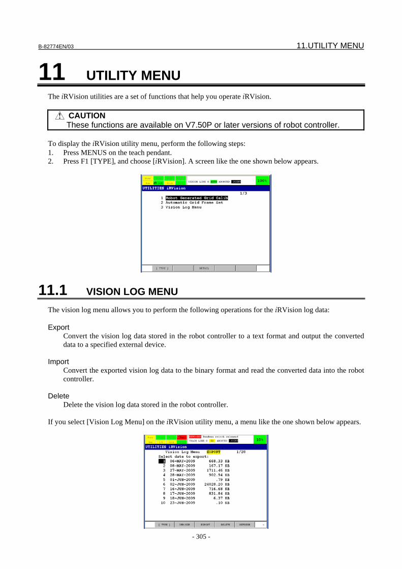
B-82774EN/03 11.UTILITY MENU
- 305 -
11 UTILITY MENU The iRVision utilities are a set of functions that help you operate iRVision.
CAUTION These functions are available on V7.50P or later versions of robot controller.
To display the iRVision utility menu, perform the following steps: 1. Press MENUS on the teach pendant. 2. Press F1 [TYPE], and choose [iRVision]. A screen like the one shown below appears.
11.1 VISION LOG MENU The vision log menu allows you to perform the following operations for the iRVision log data: Export
Convert the vision log data stored in the robot controller to a text format and output the converted data to a specified external device.
Import
Convert the exported vision log data to the binary format and read the converted data into the robot controller.
Delete
Delete the vision log data stored in the robot controller. If you select [Vision Log Menu] on the iRVision utility menu, a menu like the one shown below appears.
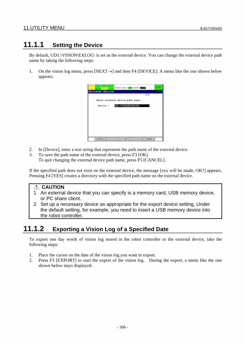
11.UTILITY MENU B-82774EN/03
- 306 -
11.1.1 Setting the Device By default, UD1:\VISION\EXLOG\ is set as the external device. You can change the external device path name by taking the following steps: 1. On the vision log menu, press [NEXT→] and then F4 [DEVICE]. A menu like the one shown below
appears.
2. In [Device], enter a text string that represents the path name of the external device. 3. To save the path name of the external device, press F3 [OK].
To quit changing the external device path name, press F5 [CANCEL]. If the specified path does not exist on the external device, the message [xxx will be made, OK?] appears. Pressing F4 [YES] creates a directory with the specified path name on the external device.
CAUTION 1 An external device that you can specify is a memory card, USB memory device,
or PC share client. 2 Set up a necessary device as appropriate for the export device setting. Under
the default setting, for example, you need to insert a USB memory device into the robot controller.
11.1.2 Exporting a Vision Log of a Specified Date To export one day worth of vision log stored in the robot controller to the external device, take the following steps: 1. Place the cursor on the date of the vision log you want to export. 2. Press F3 [EXPORT] to start the export of the vision log. During the export, a menu like the one
shown below stays displayed.
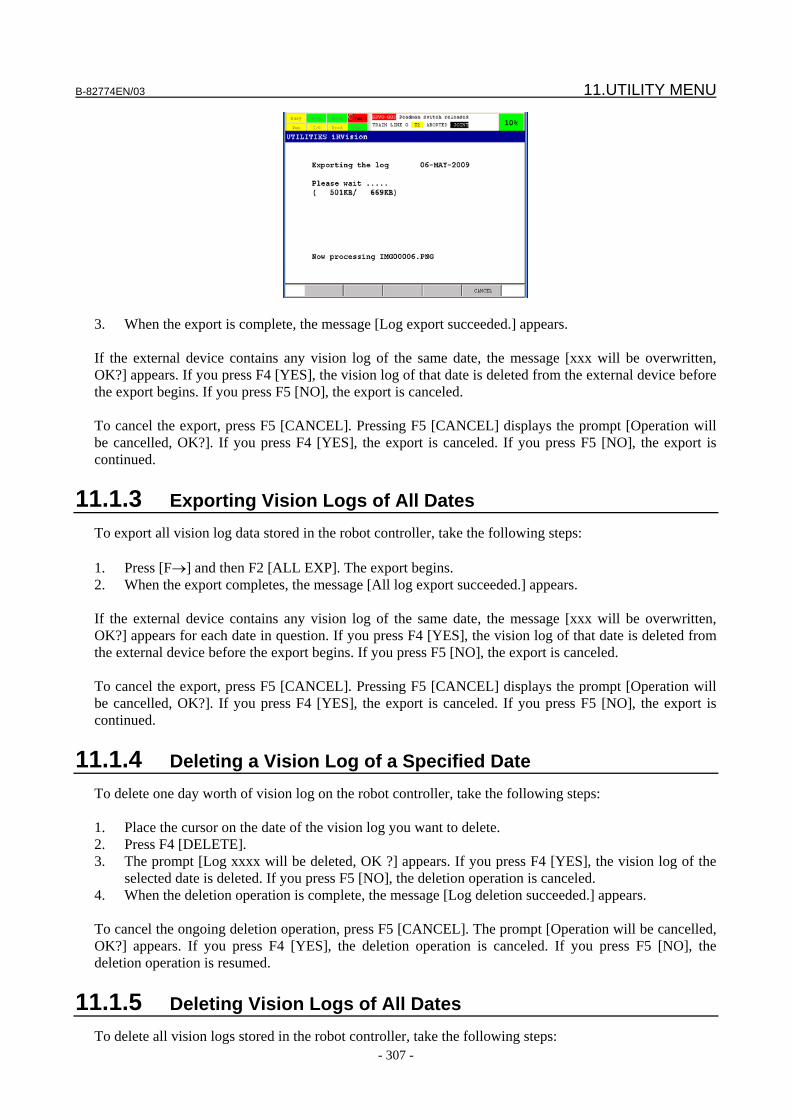
B-82774EN/03 11.UTILITY MENU
- 307 -
3. When the export is complete, the message [Log export succeeded.] appears. If the external device contains any vision log of the same date, the message [xxx will be overwritten, OK?] appears. If you press F4 [YES], the vision log of that date is deleted from the external device before the export begins. If you press F5 [NO], the export is canceled. To cancel the export, press F5 [CANCEL]. Pressing F5 [CANCEL] displays the prompt [Operation will be cancelled, OK?]. If you press F4 [YES], the export is canceled. If you press F5 [NO], the export is continued.
11.1.3 Exporting Vision Logs of All Dates To export all vision log data stored in the robot controller, take the following steps: 1. Press [F→] and then F2 [ALL EXP]. The export begins. 2. When the export completes, the message [All log export succeeded.] appears. If the external device contains any vision log of the same date, the message [xxx will be overwritten, OK?] appears for each date in question. If you press F4 [YES], the vision log of that date is deleted from the external device before the export begins. If you press F5 [NO], the export is canceled. To cancel the export, press F5 [CANCEL]. Pressing F5 [CANCEL] displays the prompt [Operation will be cancelled, OK?]. If you press F4 [YES], the export is canceled. If you press F5 [NO], the export is continued.
11.1.4 Deleting a Vision Log of a Specified Date To delete one day worth of vision log on the robot controller, take the following steps: 1. Place the cursor on the date of the vision log you want to delete. 2. Press F4 [DELETE]. 3. The prompt [Log xxxx will be deleted, OK ?] appears. If you press F4 [YES], the vision log of the
selected date is deleted. If you press F5 [NO], the deletion operation is canceled. 4. When the deletion operation is complete, the message [Log deletion succeeded.] appears. To cancel the ongoing deletion operation, press F5 [CANCEL]. The prompt [Operation will be cancelled, OK?] appears. If you press F4 [YES], the deletion operation is canceled. If you press F5 [NO], the deletion operation is resumed.
11.1.5 Deleting Vision Logs of All Dates To delete all vision logs stored in the robot controller, take the following steps:
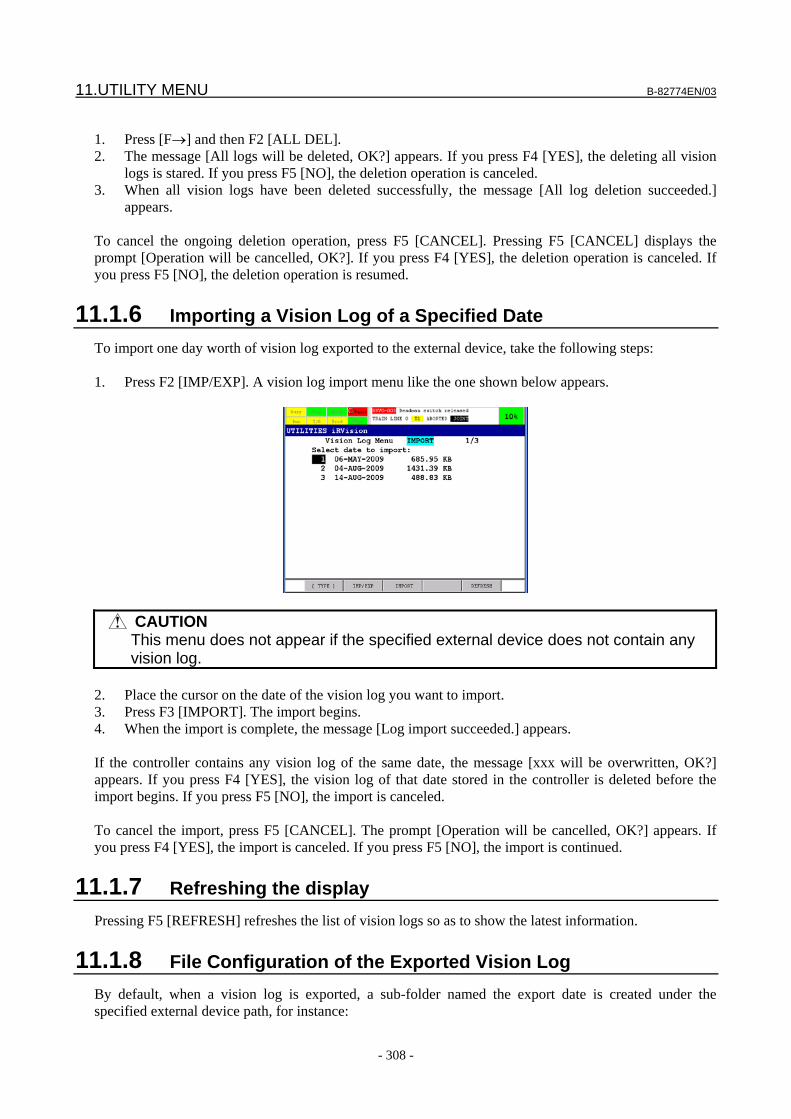
11.UTILITY MENU B-82774EN/03
- 308 -
1. Press [F→] and then F2 [ALL DEL]. 2. The message [All logs will be deleted, OK?] appears. If you press F4 [YES], the deleting all vision
logs is stared. If you press F5 [NO], the deletion operation is canceled. 3. When all vision logs have been deleted successfully, the message [All log deletion succeeded.]
appears. To cancel the ongoing deletion operation, press F5 [CANCEL]. Pressing F5 [CANCEL] displays the prompt [Operation will be cancelled, OK?]. If you press F4 [YES], the deletion operation is canceled. If you press F5 [NO], the deletion operation is resumed.
11.1.6 Importing a Vision Log of a Specified Date To import one day worth of vision log exported to the external device, take the following steps: 1. Press F2 [IMP/EXP]. A vision log import menu like the one shown below appears.
CAUTION This menu does not appear if the specified external device does not contain any
vision log. 2. Place the cursor on the date of the vision log you want to import. 3. Press F3 [IMPORT]. The import begins. 4. When the import is complete, the message [Log import succeeded.] appears. If the controller contains any vision log of the same date, the message [xxx will be overwritten, OK?] appears. If you press F4 [YES], the vision log of that date stored in the controller is deleted before the import begins. If you press F5 [NO], the import is canceled. To cancel the import, press F5 [CANCEL]. The prompt [Operation will be cancelled, OK?] appears. If you press F4 [YES], the import is canceled. If you press F5 [NO], the import is continued.
11.1.7 Refreshing the display Pressing F5 [REFRESH] refreshes the list of vision logs so as to show the latest information.
11.1.8 File Configuration of the Exported Vision Log By default, when a vision log is exported, a sub-folder named the export date is created under the specified external device path, for instance:
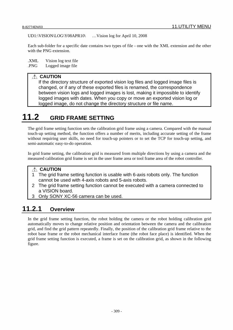
B-82774EN/03 11.UTILITY MENU
- 309 -
UD1:\VISION\LOG\Y08APR10\ …Vision log for April 10, 2008 Each sub-folder for a specific date contains two types of file - one with the XML extension and the other with the PNG extension. .XML Vision log text file .PNG Logged image file
CAUTION If the directory structure of exported vision log files and logged image files is
changed, or if any of these exported files is renamed, the correspondence between vision logs and logged images is lost, making it impossible to identify logged images with dates. When you copy or move an exported vision log or logged image, do not change the directory structure or file name.
11.2 GRID FRAME SETTING The grid frame setting function sets the calibration grid frame using a camera. Compared with the manual touch-up setting method, the function offers a number of merits, including accurate setting of the frame without requiring user skills, no need for touch-up pointers or to set the TCP for touch-up setting, and semi-automatic easy-to-do operation. In grid frame setting, the calibration grid is measured from multiple directions by using a camera and the measured calibration grid frame is set in the user frame area or tool frame area of the robot controller.
CAUTION 1 The grid frame setting function is usable with 6-axis robots only. The function
cannot be used with 4-axis robots and 5-axis robots. 2 The grid frame setting function cannot be executed with a camera connected to
a VISION board. 3 Only SONY XC-56 camera can be used.
11.2.1 Overview In the grid frame setting function, the robot holding the camera or the robot holding calibration grid automatically moves to change relative position and orientation between the camera and the calibration grid, and find the grid pattern repeatedly. Finally, the position of the calibration grid frame relative to the robot base frame or the robot mechanical interface frame (the robot face place) is identified. When the grid frame setting function is executed, a frame is set on the calibration grid, as shown in the following figure.
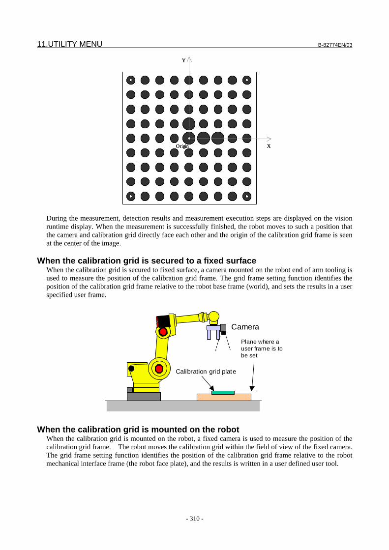
11.UTILITY MENU B-82774EN/03
- 310 -
X
Y
Origin X
Y
Origin
During the measurement, detection results and measurement execution steps are displayed on the vision runtime display. When the measurement is successfully finished, the robot moves to such a position that the camera and calibration grid directly face each other and the origin of the calibration grid frame is seen at the center of the image.
When the calibration grid is secured to a fixed surface When the calibration grid is secured to fixed surface, a camera mounted on the robot end of arm tooling is used to measure the position of the calibration grid frame. The grid frame setting function identifies the position of the calibration grid frame relative to the robot base frame (world), and sets the results in a user specified user frame.
Camera
Plane where a user frame is to be set
Calibration grid plate
When the calibration grid is mounted on the robot When the calibration grid is mounted on the robot, a fixed camera is used to measure the position of the calibration grid frame. The robot moves the calibration grid within the field of view of the fixed camera. The grid frame setting function identifies the position of the calibration grid frame relative to the robot mechanical interface frame (the robot face plate), and the results is written in a user defined user tool.
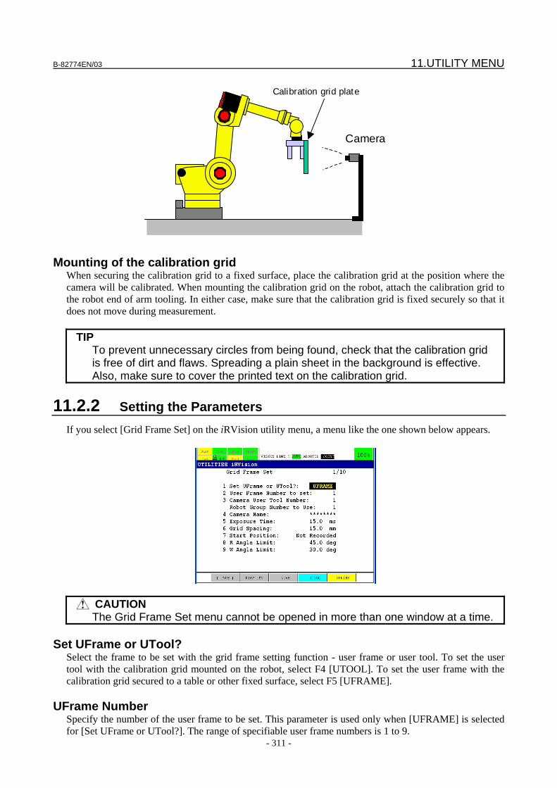
B-82774EN/03 11.UTILITY MENU
- 311 -
Camera
Calibration grid plate
Mounting of the calibration grid When securing the calibration grid to a fixed surface, place the calibration grid at the position where the camera will be calibrated. When mounting the calibration grid on the robot, attach the calibration grid to the robot end of arm tooling. In either case, make sure that the calibration grid is fixed securely so that it does not move during measurement.
TIP To prevent unnecessary circles from being found, check that the calibration grid
is free of dirt and flaws. Spreading a plain sheet in the background is effective. Also, make sure to cover the printed text on the calibration grid.
11.2.2 Setting the Parameters If you select [Grid Frame Set] on the iRVision utility menu, a menu like the one shown below appears.
CAUTION The Grid Frame Set menu cannot be opened in more than one window at a time.
Set UFrame or UTool?
Select the frame to be set with the grid frame setting function - user frame or user tool. To set the user tool with the calibration grid mounted on the robot, select F4 [UTOOL]. To set the user frame with the calibration grid secured to a table or other fixed surface, select F5 [UFRAME].
UFrame Number Specify the number of the user frame to be set. This parameter is used only when [UFRAME] is selected for [Set UFrame or UTool?]. The range of specifiable user frame numbers is 1 to 9.
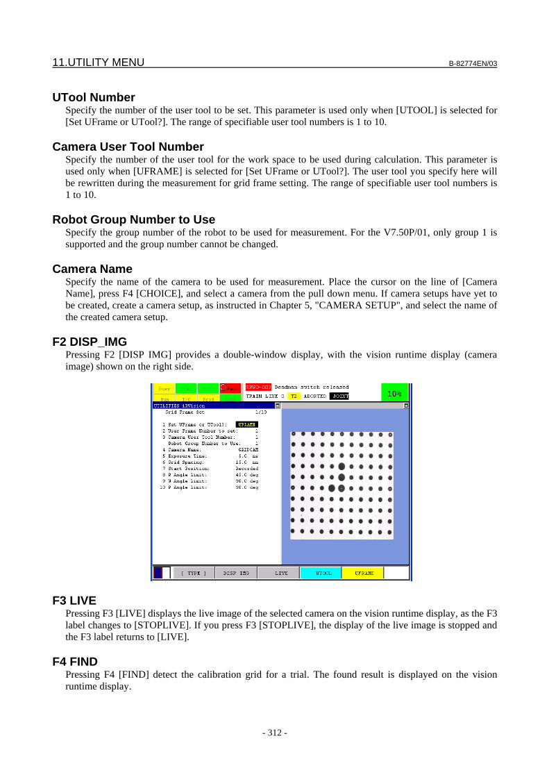
11.UTILITY MENU B-82774EN/03
- 312 -
UTool Number
Specify the number of the user tool to be set. This parameter is used only when [UTOOL] is selected for [Set UFrame or UTool?]. The range of specifiable user tool numbers is 1 to 10.
Camera User Tool Number Specify the number of the user tool for the work space to be used during calculation. This parameter is used only when [UFRAME] is selected for [Set UFrame or UTool?]. The user tool you specify here will be rewritten during the measurement for grid frame setting. The range of specifiable user tool numbers is 1 to 10.
Robot Group Number to Use Specify the group number of the robot to be used for measurement. For the V7.50P/01, only group 1 is supported and the group number cannot be changed.
Camera Name Specify the name of the camera to be used for measurement. Place the cursor on the line of [Camera Name], press F4 [CHOICE], and select a camera from the pull down menu. If camera setups have yet to be created, create a camera setup, as instructed in Chapter 5, "CAMERA SETUP", and select the name of the created camera setup.
F2 DISP_IMG Pressing F2 [DISP IMG] provides a double-window display, with the vision runtime display (camera image) shown on the right side.
F3 LIVE Pressing F3 [LIVE] displays the live image of the selected camera on the vision runtime display, as the F3 label changes to [STOPLIVE]. If you press F3 [STOPLIVE], the display of the live image is stopped and the F3 label returns to [LIVE].
F4 FIND Pressing F4 [FIND] detect the calibration grid for a trial. The found result is displayed on the vision runtime display.
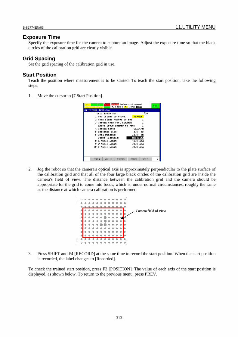
B-82774EN/03 11.UTILITY MENU
- 313 -
Exposure Time Specify the exposure time for the camera to capture an image. Adjust the exposure time so that the black circles of the calibration grid are clearly visible.
Grid Spacing Set the grid spacing of the calibration grid in use.
Start Position Teach the position where measurement is to be started. To teach the start position, take the following steps: 1. Move the cursor to [7 Start Position].
2. Jog the robot so that the camera's optical axis is approximately perpendicular to the plate surface of
the calibration grid and that all of the four large black circles of the calibration grid are inside the camera's field of view. The distance between the calibration grid and the camera should be appropriate for the grid to come into focus, which is, under normal circumstances, roughly the same as the distance at which camera calibration is performed.
Camera field of viewCamera field of view
3. Press SHIFT and F4 [RECORD] at the same time to record the start position. When the start position
is recorded, the label changes to [Recorded]. To check the trained start position, press F3 [POSITION]. The value of each axis of the start position is displayed, as shown below. To return to the previous menu, press PREV.
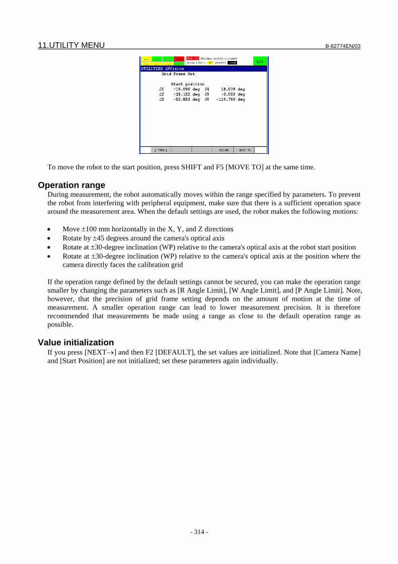
11.UTILITY MENU B-82774EN/03
- 314 -
To move the robot to the start position, press SHIFT and F5 [MOVE TO] at the same time.
Operation range During measurement, the robot automatically moves within the range specified by parameters. To prevent the robot from interfering with peripheral equipment, make sure that there is a sufficient operation space around the measurement area. When the default settings are used, the robot makes the following motions: • Move ±100 mm horizontally in the X, Y, and Z directions • Rotate by ±45 degrees around the camera's optical axis • Rotate at ±30-degree inclination (WP) relative to the camera's optical axis at the robot start position • Rotate at ±30-degree inclination (WP) relative to the camera's optical axis at the position where the
camera directly faces the calibration grid If the operation range defined by the default settings cannot be secured, you can make the operation range smaller by changing the parameters such as [R Angle Limit], [W Angle Limit], and [P Angle Limit]. Note, however, that the precision of grid frame setting depends on the amount of motion at the time of measurement. A smaller operation range can lead to lower measurement precision. It is therefore recommended that measurements be made using a range as close to the default operation range as possible.
Value initialization If you press [NEXT→] and then F2 [DEFAULT], the set values are initialized. Note that [Camera Name] and [Start Position] are not initialized; set these parameters again individually.

B-82774EN/03 11.UTILITY MENU
- 315 -
11.2.3 Run Measurement Pressing SHIFT and F5 [EXECUTE] at the same time starts measurement, causing the robot to start moving. During execution watch image displayed and verify that there are no improperly found calibration grid circles.
CAUTION 1 Releasing SHIFT while measurement is in progress stops the measurement. In
that case, perform the measurement again. 2 During measurement, if you perform any operation intended to move to another
menu, such as pressing SELECT, the measurement is stopped. In that case, visit the Grid Frame Set menu again and perform the measurement again.
3 The robot usually performs operations within an expected range according to the parameter setting. However, the robot can make a motion beyond an expected range, depending on the parameter setting. When running the Grid Frame Set, check that the related parameters are set correctly and decrease the override to 30% or less to ensure that the robot does not interfere with peripheral equipments.
4 If another program is paused, the Grid Frame Set may not be able to move the robot. In that case, abort all the programs using the FUNC menu.
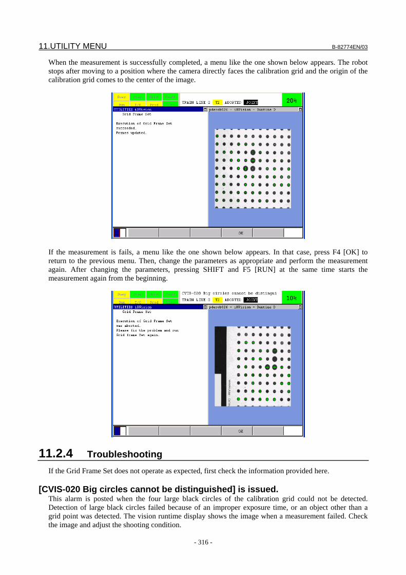
11.UTILITY MENU B-82774EN/03
- 316 -
When the measurement is successfully completed, a menu like the one shown below appears. The robot stops after moving to a position where the camera directly faces the calibration grid and the origin of the calibration grid comes to the center of the image.
If the measurement is fails, a menu like the one shown below appears. In that case, press F4 [OK] to return to the previous menu. Then, change the parameters as appropriate and perform the measurement again. After changing the parameters, pressing SHIFT and F5 [RUN] at the same time starts the measurement again from the beginning.
11.2.4 Troubleshooting If the Grid Frame Set does not operate as expected, first check the information provided here.
[CVIS-020 Big circles cannot be distinguished] is issued. This alarm is posted when the four large black circles of the calibration grid could not be detected. Detection of large black circles failed because of an improper exposure time, or an object other than a grid point was detected. The vision runtime display shows the image when a measurement failed. Check the image and adjust the shooting condition.
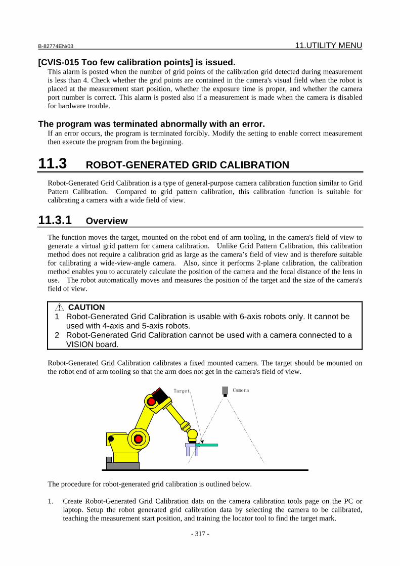
B-82774EN/03 11.UTILITY MENU
- 317 -
[CVIS-015 Too few calibration points] is issued. This alarm is posted when the number of grid points of the calibration grid detected during measurement is less than 4. Check whether the grid points are contained in the camera's visual field when the robot is placed at the measurement start position, whether the exposure time is proper, and whether the camera port number is correct. This alarm is posted also if a measurement is made when the camera is disabled for hardware trouble.
The program was terminated abnormally with an error. If an error occurs, the program is terminated forcibly. Modify the setting to enable correct measurement then execute the program from the beginning.
11.3 ROBOT-GENERATED GRID CALIBRATION Robot-Generated Grid Calibration is a type of general-purpose camera calibration function similar to Grid Pattern Calibration. Compared to grid pattern calibration, this calibration function is suitable for calibrating a camera with a wide field of view.
11.3.1 Overview The function moves the target, mounted on the robot end of arm tooling, in the camera's field of view to generate a virtual grid pattern for camera calibration. Unlike Grid Pattern Calibration, this calibration method does not require a calibration grid as large as the camera’s field of view and is therefore suitable for calibrating a wide-view-angle camera. Also, since it performs 2-plane calibration, the calibration method enables you to accurately calculate the position of the camera and the focal distance of the lens in use. The robot automatically moves and measures the position of the target and the size of the camera's field of view.
CAUTION 1 Robot-Generated Grid Calibration is usable with 6-axis robots only. It cannot be
used with 4-axis and 5-axis robots. 2 Robot-Generated Grid Calibration cannot be used with a camera connected to a
VISION board. Robot-Generated Grid Calibration calibrates a fixed mounted camera. The target should be mounted on the robot end of arm tooling so that the arm does not get in the camera's field of view.
CameraTarget
The procedure for robot-generated grid calibration is outlined below. 1. Create Robot-Generated Grid Calibration data on the camera calibration tools page on the PC or
laptop. Setup the robot generated grid calibration data by selecting the camera to be calibrated, teaching the measurement start position, and training the locator tool to find the target mark.
11.UTILITY MENU B-82774EN/03
- 318 -
2. Measure the position of the target mounted on the robot end of arm tooling. 3. Measure the size of the camera's field of view, and generate a calibration program. 4. Execute the generated calibration program to calibrate the camera. As long as the position of the target mounted on the robot end of arm tooling is not changed, you can re-calibrate the camera only by taking the step 4.
11.3.2 Structure of the Menus Here, the menu structure of Robot-Generated Grid Calibration is first described.
11.3.2.1 Main Menu If you select [Robot-Generated Grid Calibration] in the iRVision utility menu, a menu like the one shown below appears. This is the main menu for Robot-Generated Grid Calibration.
CAUTION Robot-Generated Grid Calibration menu cannot be opened in more than one
window at a time.
Calibration Data Select a camera calibration. Place the cursor on this line and press F4 [CHOICE]. A camera calibration list is displayed. From this list, select the camera calibration you want to train. Pressing F3 [DETAIL] with the cursor placed on this line lets you view the details of the currently selected camera calibration.
Target Position This item indicates whether the position of the target mounted on the robot end of arm tooling has been recorded. If the position of the target has been recorded, [Recorded] is displayed. Otherwise, [Not Recorded] is displayed. Pressing F3 [DETAIL] with the cursor placed on this line lets you view the position information of the recorded target. If you place the cursor on this line and press SHIFT and F5 [RUN] at the same time, the robot moves and measures the position of the target.
Program Generation Generate a TP program for camera calibration. If you place the cursor on this line and press SHIFT and F5 [RUN] at the same time, the robot moves and measures the size of the camera's field of view to generate a calibration program automatically.
B-82774EN/03 11.UTILITY MENU
- 319 -
F2 DISP_IMG Pressing F2 [DISP_IMG] shows the menu for Robot-Generated Grid Calibration and the vision runtime display in a double-window display, as shown below.
11.3.2.2 Calibration Data Menu If you press F3 [DETAIL] with the cursor placed on [Calibration Data] in the main menu for Robot-Generated Grid Calibration, a menu like the one shown below appears. This menu displays what has been set in the Robot-Generated Grid Calibration setup page on PC. Normally, there is no item you need to set on this menu.
Calibration Data The name of the selected camera calibration is displayed. Pressing F4 [CHOICE] with the cursor placed on this line shows a list of camera calibration that you can select. From this list, you can select a camera calibration you want to teach.
11.UTILITY MENU B-82774EN/03
- 320 -
Camera Setup The name of the camera specified in the selected camera calibration is displayed.
Robot-mounted [NO] is displayed if the camera is secured to a fixed surface, or [YES] is displayed if it is mounted on the robot end of arm tooling.
CAUTION For V7.50P/01, Robot-Generated Grid Calibration does not support a
robot-mounted camera.
Application Frame The number of the application user frame specified in the selected camera calibration is displayed. In the case of 2D application, the XY plane of the application user frame needs to be parallel to the plane where the workpiece is to be offset.
Start Position This item indicates whether the measurement start position is recorded in the selected camera calibration. If the start position is recorded, [Recorded] is displayed. Otherwise, [Not Recorded] is displayed. Pressing F3 [POSITION] with the cursor placed on this line displays the start position menu.
UTool for Work Space Robot-Generated Grid Calibration uses a user tool for the work space when measuring the position of the target or generating a calibration program. Here, specify the number of the user tool for the work space. Since the function conducts the measurement as it rewrites the values of the specified user tool, specify the number of a user tool whose values can be changed without causing any problem.
Num. of Grid (Column) Specify the number of grid points of the grid pattern that the robot draws by moving the target. Here, set the number of grid points to be created in the horizontal direction of the image.
Num. of Grid (Row) Specify the number of grid points of the grid pattern that the robot draws by moving the target. Here, set the number of grid points to be created in the vertical direction of the image.
Program Name Specify the name of the calibration program to be generated. By default, this program name is the same as the name of the selected camera calibration. Normally, you do not need to change the default name.
B-82774EN/03 11.UTILITY MENU
- 321 -
11.3.2.3 Target Position Menu If you press F3 [POSITION] with the cursor placed on [Target Position] in the main menu for Robot-Generated Grid Calibration, a menu like the one shown below appears.
11.3.2.4 Start Position Menu If you press F3 [POSITION] with the cursor placed on [Start Position] in the calibration data menu, a menu like the one shown below appears.
F4 RECORD If you press SHIFT and F4 [RECORD] at the same time causes the current robot position to be recorded as the measurement start position. The position is recorded in the joint format.
11.UTILITY MENU B-82774EN/03
- 322 -
F5 MOVE_TO If you press SHIFT and F4 [MOVE_TO] at the same time moves the robot to the currently recorded measurement start position.
11.3.3 Performing Calibration Perform Robot-Generated Grid Calibration.
11.3.3.1 Selecting and Mounting the Target Select the target mark to be used for calibration.
Geometry of the target The target must meet the following conditions: • The features to be taught are on the same one plane. • The target has a geometry for which any rotation of ±45° or so can be identified. • The target has a geometry whose size can be identified.
Examples of appropriate target geometries:
Examples of inappropriate target geometries:
The rotation angle cannot be identified. The size cannot be identified.
Size of the target
Make sure that the size of the target, when captured as an image, is 80 to 100 pixels in both vertical and horizontal directions. For example, when the camera's field of view is about 900 mm (8-mm lens; distance between camera and target is 2000 mm or so), prepare a target that is 120 to 160 mm in diameter.
Mounting the target Mount the target at the robot end of arm tooling. Make sure that the target does not get behind the robot arm or the tooling even when the robot moves in the camera's field of view.
CAUTION Make sure that the target is fixed securely to the robot end of arm tooling so that
it remains in place while the robot moves.

B-82774EN/03 11.UTILITY MENU
- 323 -
TIP 1 Normally, the robot position and posture are set so that the range of robot
motion becomes maximal when the robot actually operates. Therefore, mounting the target so that it can be captured by the camera when the robot is in a posture that it takes during operation makes it easier to secure the range of robot motion.
2 Positioning pins or other appropriate means may be used so that the target can be mounted at the same position for each measurement. This way, a robot program generated for a previous calibration operation can be used for re-calibration.
11.3.3.2 Setting the Location Parameters
On the iRVision setup page of the PC, set the parameters for finding the target. If you open the Robot-Generated Grid Calibration setup page, a page like the one shown below appears.
Set the following parameters:
Camera Setup Select the camera to be calibrated. When you select a camera, the corresponding camera positioning state is displayed to the left of the drop-down box.
Exposure Time Set the exposure time to make sure that the target is detected easily. The exposure time you specify here is used only for calibration. For details of the individual items to be set, see Subsection 4.12.10, "Setting an Exposure Mode".
Robot to be offset Specify the motion group number of the robot to be offset.
CAUTION This calibration function can be used only for group 1 of the controller to which
the camera is connected.
11.UTILITY MENU B-82774EN/03
- 324 -
Application User Frame Specify the application user frame to be used for robot compensation. When camera calibration is performed for the user frame 1, for example, a vision process that uses this camera calibration calculates offset data represented in the user frame 1. Therefore, robot motion offset is performed based on the user frame 1. In 2-D applications, the XY plane of the application user frame must be parallel to the target workpiece plane. Examples are given below.
X
Z App. Frame
Camera
App. Frame
X Z
Camera
When the workpiece moves horizontally When the workpiece moves on a slanting plane:
CAUTION
The application user frame must be set before the camera calibration is performed. If the application user frame is changed after calibrating the camera, calibrate the camera again.
Target Held By Robot
The target positioning method information necessary to calibrate the currently selected camera is displayed. [Yes] is shown if the camera is a fixed camera, and [No] is shown if the camera is a robot-mounted camera.
Image Logging Mode Specify whether to save logged images when performing calibration.
Plane spacing Specify the spacing between calibration planes 1 and 2. An optimal calibration plane spacing is 10% of the spacing between the camera and calibration plane 1. If you enter a positive value when the Z-axis of the application user frame is directed toward the camera, or if you enter a negative value when the Z-axis is in the opposite direction, calibration plane 2 is located closer to the camera relative to calibration plane 1. This reduces the risk of the robot interfering with peripheral equipment when moving.
B-82774EN/03 11.UTILITY MENU
- 325 -
Start Position Teach the measurement start position. This start position should be set so that the target mounted on the robot end of arm tooling comes roughly at the center of the camera’s field of view. The height of the start position is equal to that of the calibration plane 1. During camera calibration, the robot moves in parallel to the XY plane of the application user frame, while maintaining the posture it takes at the start position. Jog the robot to a place that is appropriate as the start position, and press the RECORD button to record the start position.
Camera
Application User Frame
Target
Calibration
Plane 1
Calibration
Plane 2
Start Position
Teaching the locator tool Teach the model pattern of the target in the locator tool setup page. 1. Move the robot to the recorded start position. 2. In the tree view, choose the GPM locator tool. 3. Enclose the target on the image by a rectangle, and teach the model pattern. 4. Check the [Training Stability] items of the model pattern to see if [Good] is shown for [Location],
[Orientation], and [Scale], respectively. If [None] is shown for any of these items, calibration cannot be performed properly. In that case, use a different shape of target mark.
5. Set the range of [Angle] to be searched to ±30°. 6. Check the [Scale] check box, and set the range of [Scale] to be searched to 95% to 120%. If the
plane spacing has been changed, change the maximum value to an appropriate value. 7. Enable the [Aspect Ratio] search in the same way, and set the range of [Aspect Ratio] to be searched
to 90% to 100%. For details of the individual items to be set for the GPM locator tool, see Section 8.1, "GPM LOCATOR TOOL".
11.UTILITY MENU B-82774EN/03
- 326 -
11.3.3.3 Measuring the Target Position Measures the position of the target mounted on the robot end of arm tooling.
1. Visit the main menu for Robot-Generated Grid Calibration on the teach pendant. 2. Place the cursor on [Calibration Data], press F4 [CHOICE], and select a camera calibration. 3. Place the cursor on [Target Position]. 4. Enable the teach pendant, and clear the alarm. 5. Press SHIFT and F5 [RUN] at the same time to measure the position of the target. Keep holding
down SHIFT while the measurement is in progress. 6. When the measurement is complete, the robot stops and the message [Measurement is successfully
finished.] appears on the screen. 7. Press F4 [OK] to return to the main menu. If the last target position measurement was aborted before completion, the message [Are you sure to resume?] appears when you attempt to perform the target position measurement again. To resume the measurement, press SHIFT and F4 [Resume] at the same time. To restart the measurement from the beginning, press SHIFT and F5 [Restart] at the same time.
CAUTION If the camera calibration setup page is opened on the PC, Robot-Generated Grid
Calibration cannot perform the measurement. Make sure that the setup page of the PC is closed. You can see the status of the measurement using the vision runtime display.
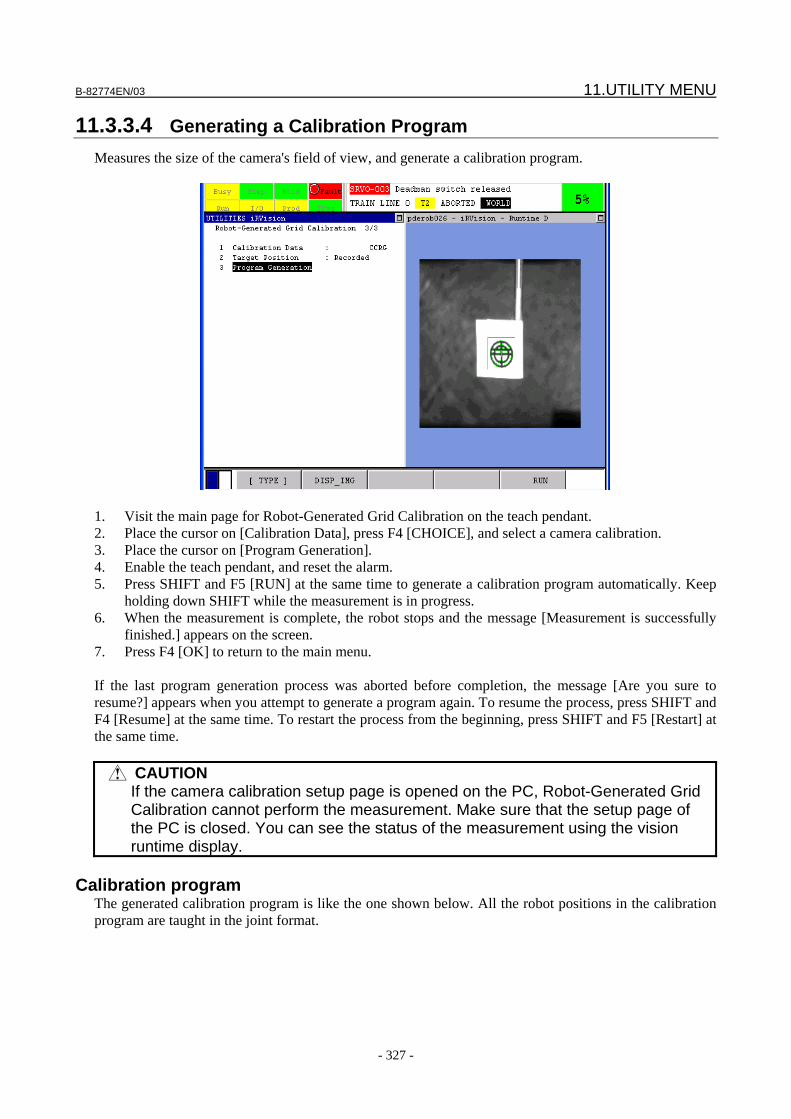
B-82774EN/03 11.UTILITY MENU
- 327 -
11.3.3.4 Generating a Calibration Program Measures the size of the camera's field of view, and generate a calibration program.
1. Visit the main page for Robot-Generated Grid Calibration on the teach pendant. 2. Place the cursor on [Calibration Data], press F4 [CHOICE], and select a camera calibration. 3. Place the cursor on [Program Generation]. 4. Enable the teach pendant, and reset the alarm. 5. Press SHIFT and F5 [RUN] at the same time to generate a calibration program automatically. Keep
holding down SHIFT while the measurement is in progress. 6. When the measurement is complete, the robot stops and the message [Measurement is successfully
finished.] appears on the screen. 7. Press F4 [OK] to return to the main menu. If the last program generation process was aborted before completion, the message [Are you sure to resume?] appears when you attempt to generate a program again. To resume the process, press SHIFT and F4 [Resume] at the same time. To restart the process from the beginning, press SHIFT and F5 [Restart] at the same time.
CAUTION If the camera calibration setup page is opened on the PC, Robot-Generated Grid
Calibration cannot perform the measurement. Make sure that the setup page of the PC is closed. You can see the status of the measurement using the vision runtime display.
Calibration program
The generated calibration program is like the one shown below. All the robot positions in the calibration program are taught in the joint format.
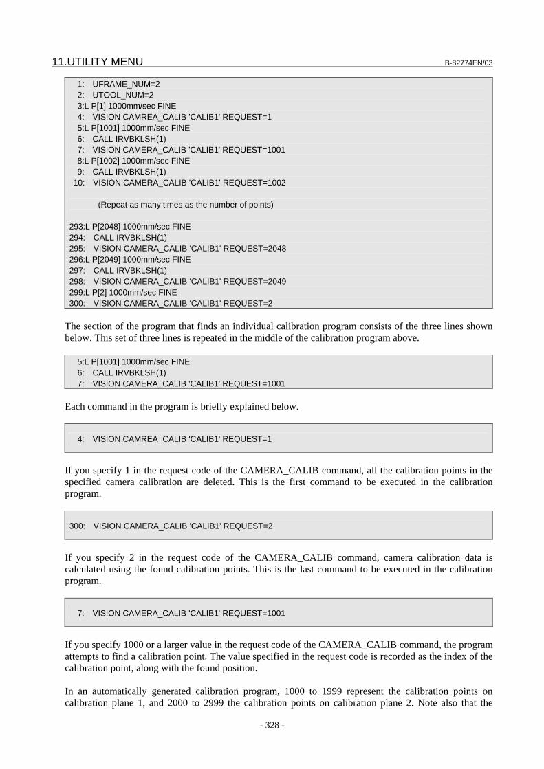
11.UTILITY MENU B-82774EN/03
- 328 -
1: UFRAME_NUM=2 2: UTOOL_NUM=2 3:L P[1] 1000mm/sec FINE 4: VISION CAMREA_CALIB 'CALIB1' REQUEST=1 5:L P[1001] 1000mm/sec FINE 6: CALL IRVBKLSH(1) 7: VISION CAMERA_CALIB 'CALIB1' REQUEST=1001 8:L P[1002] 1000mm/sec FINE 9: CALL IRVBKLSH(1) 10: VISION CAMERA_CALIB 'CALIB1' REQUEST=1002 (Repeat as many times as the number of points) 293:L P[2048] 1000mm/sec FINE 294: CALL IRVBKLSH(1) 295: VISION CAMERA_CALIB 'CALIB1' REQUEST=2048 296:L P[2049] 1000mm/sec FINE 297: CALL IRVBKLSH(1) 298: VISION CAMERA_CALIB 'CALIB1' REQUEST=2049 299:L P[2] 1000mm/sec FINE 300: VISION CAMERA_CALIB 'CALIB1' REQUEST=2
The section of the program that finds an individual calibration program consists of the three lines shown below. This set of three lines is repeated in the middle of the calibration program above. 5:L P[1001] 1000mm/sec FINE 6: CALL IRVBKLSH(1) 7: VISION CAMERA_CALIB 'CALIB1' REQUEST=1001
Each command in the program is briefly explained below.
4: VISION CAMREA_CALIB 'CALIB1' REQUEST=1
If you specify 1 in the request code of the CAMERA_CALIB command, all the calibration points in the specified camera calibration are deleted. This is the first command to be executed in the calibration program.
300: VISION CAMERA_CALIB 'CALIB1' REQUEST=2
If you specify 2 in the request code of the CAMERA_CALIB command, camera calibration data is calculated using the found calibration points. This is the last command to be executed in the calibration program.
7: VISION CAMERA_CALIB 'CALIB1' REQUEST=1001
If you specify 1000 or a larger value in the request code of the CAMERA_CALIB command, the program attempts to find a calibration point. The value specified in the request code is recorded as the index of the calibration point, along with the found position. In an automatically generated calibration program, 1000 to 1999 represent the calibration points on calibration plane 1, and 2000 to 2999 the calibration points on calibration plane 2. Note also that the
B-82774EN/03 11.UTILITY MENU
- 329 -
index of the position data of the preceding motion statement is the same as the request code that is passed to the CAMERA_CALIB command. Calibration points do not necessarily need to be found in the order of request codes. If a calibration point is found twice with the same request code, the data of the calibration point that is found first is overwritten by the data of the calibration point found later.
6: CALL IRVBKLSH(1)
If the KAREL program IRVBKLSH.PC is called, the robot performs an operation intended to remove the backlash effect at its current position. As the argument, specify the motion group number of the robot that performs the backlash removal operation.
11.3.3.5 Executing the Calibration Program Select the automatically generated calibration program in the SELECT menu, and play it back from the first line to calibrate the camera.
CAUTION If running the program as is can cause interference, use lower override values.
In this case, execute the program while making sure that no interference occurs during operation.
Each calibration point in the automatically generated calibration program can be re-taught or deleted as necessary. If there is any calibration point that causes the robot to interfere with peripheral equipment, re-teach that point to move it to a position where it does not cause interference, or delete the calibration point. When deleting a calibration point, delete not only the motion statement but also the lines of IRVBKLSH and the CAMERA_CALIB command that are executed after the motion statement. If there is any calibration point that hinders the robot operation because it is near singularity, re-teach that point to move it to a position where it can avoid singularity, or delete the calibration point. When deleting a calibration point, delete not only the motion statement but also the lines of IRVBKLSH and the CAMERA_CALIB command that are executed after the motion statement. When re-teaching a calibration point, you may place the target closer to or further away from the camera within a range in which the camera lens remains in focus.
CAUTION The calibration program does not stop even if the target fails to be found or it is
found incorrectly during the program execution. After the program ends, open the robot-generated grid calibration setup page on the PC and check to see if there is any point incorrectly found.
TIP As long as the position where the target is mounted remains unchanged, you
can re-calibrate the camera simply by executing an existing automatically generated calibration program.

11.UTILITY MENU B-82774EN/03
- 330 -
11.3.3.6 Checking Calibration Points Check the calibration points that have been found. Open the Robot-Generated Grid Calibration setup page on the PC and click the [Points] tab. A page like the one shown below appears.
The image has a blue crosshair plotted on each calibration point in calibration plane 1 and a purple crosshair plotted on each calibration point in calibration plane 2, at the center of each circle that has been found. A calibration point number is shown at the lower right of each crosshair. A red crosshair shows the 3D position of an individual circle that is obtained by projecting the circle onto the image by means of the calculated calibration data. Since blue and purple crosshairs are plotted after red crosshairs, a red crosshair is not visible if a blue or purple crosshair and a red crosshair are plotted at the same position.
Vt, Hz The coordinate values of the found calibration points on the image are displayed.
X, Y, Z The coordinate values of the grid points on the calibration grid frame are displayed.
Error The distance between the centers of the blue/purple crosshairs and red crosshairs plotted on the image is displayed. A smaller value indicates more accurate calibration.
Deleting a calibration point If a crosshair is displayed at a location where no grid point is present, enter the index number of that point in the text box to the left of the [Delete] button and then click the [Delete] button. The specified point is deleted from the list, and the calibration data is automatically recalculated.
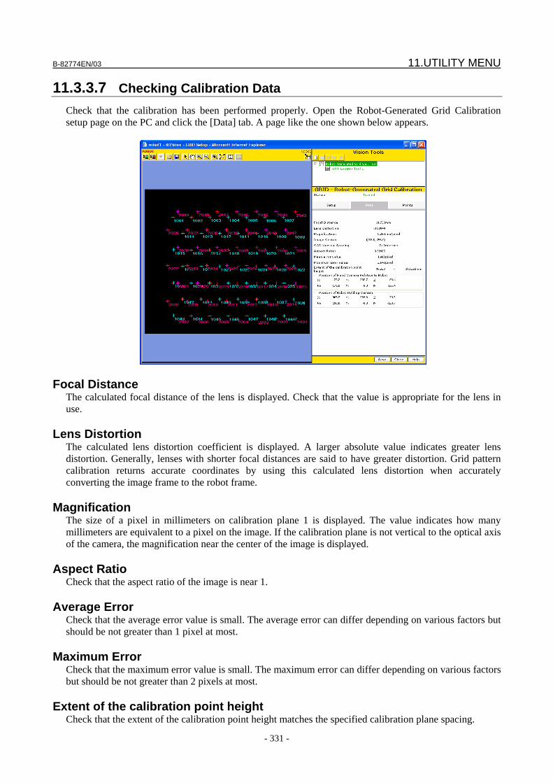
B-82774EN/03 11.UTILITY MENU
- 331 -
11.3.3.7 Checking Calibration Data Check that the calibration has been performed properly. Open the Robot-Generated Grid Calibration setup page on the PC and click the [Data] tab. A page like the one shown below appears.
Focal Distance The calculated focal distance of the lens is displayed. Check that the value is appropriate for the lens in use.
Lens Distortion The calculated lens distortion coefficient is displayed. A larger absolute value indicates greater lens distortion. Generally, lenses with shorter focal distances are said to have greater distortion. Grid pattern calibration returns accurate coordinates by using this calculated lens distortion when accurately converting the image frame to the robot frame.
Magnification The size of a pixel in millimeters on calibration plane 1 is displayed. The value indicates how many millimeters are equivalent to a pixel on the image. If the calibration plane is not vertical to the optical axis of the camera, the magnification near the center of the image is displayed.
Aspect Ratio Check that the aspect ratio of the image is near 1.
Average Error Check that the average error value is small. The average error can differ depending on various factors but should be not greater than 1 pixel at most.
Maximum Error Check that the maximum error value is small. The maximum error can differ depending on various factors but should be not greater than 2 pixels at most.
Extent of the calibration point height Check that the extent of the calibration point height matches the specified calibration plane spacing.
11.UTILITY MENU B-82774EN/03
- 332 -
Position of Fixed Camera Relative to Application User Frame
Check that the position of the fixed camera relative to the user frame to be used for offsetting has been calculated correctly.
B-82774EN/03 12.CALIBRATION GRID
- 333 -
12 CALIBRATION GRID This chapter provides information about a calibration grid used for iRVision camera calibration.
12.1 CALIBRATION GRID iRVision performs camera calibration by using a calibration grid on which a predetermined pattern is drawn. When a grid as shown below is viewed through the camera, iRVision will automatically recognize the positional relationship between the calibration grid and the camera, lens distortion, focal distance, etc.
X
Y
Origin X
Y
Origin
All of the black circles are arranged so that they are uniformly spaced horizontally and perpendicularly. Four larger black circles placed in the vicinity of the center indicate the origin and directions of a coordinate system as shown. The ratio of the diameter of a large circle to that of a small circle is about 10:6. The grid points at the center and the four corners contain a white circle with a diameter of 1 mm. These white circles are used when a coordinate system is set up by touching up them with the TCP of the robot.
12.2 CALIBRATION GRID FRAME The calibration grid might be secured to a table or another place or mounted on the robot end of arm tooling according to the applications. In either case, when camera calibration is performed, it is necessary to set information about the installation position of the calibration grid as viewed from the robot. That information is called the calibration grid frame. This section describes how to teach the calibration grid frame. When the calibration grid is mounted to a fixed surface, the position of the calibration grid frame relative to the robot base frame should be set in the user frame area. On the other hand, when the calibration grid is mounted on a robot, the position of the calibration grid frame relative to the robot mechanical interface frame (robot face plate) should be set in the user tool area. Two methods of setting the calibration grid frame are available: With one method, the calibration grid frame is set by physically teaching the calibration grid with a pointer attached on the robot end of the arm
12.CALIBRATION GRID B-82774EN/03
- 334 -
tooling. With the other method, the calibration grid frame is set by measuring the grid pattern with a camera without contact. In the following subsections, these two methods are explained.
12.2.1 Setting Based on Touch-up This section explains how to set the calibration grid frame with the legacy method, namely physically touching-up the calibration grid with a pointer mounted on a robot end of the arm tooling.
When the calibration grid is secured to a fixed surface When the calibration grid is installed in a fixed place, the position of the calibration grid frame relative to the robot base frame should be set in the user frame area. After a pointer for touch-up is mounted on the robot end of the arm tooling and TCP is set to the tip of the pointer, select [User Frame Setup / Four Points], and teach the four points shown in the figure below by touch-up operation with the TCP of the robot.
SETUP Frames User Frame Setup / Four Points 1/5 Frame Number: 1 X: 0.0 Y: 0.0 Z: 0.0 W: 0.0 P: 0.0 R: 0.0 Comment:******************** Orient Origin Point: UNINIT X Direction Point: UNINIT Y Direction Point: UNINIT System Origin: UNINIT Active UFRAME $MNUFRAMENUM[1] = 0 [ TYPE ][METHOD] FRAME
Orient Origin X Direction
System
Origin
Y Direction
When the calibration grid is mounted on the robot end of arm tooling
When the calibration grid is mounted on the robot end of arm tooling, the position of the calibration grid frame relative to the robot mechanical interface frame (robot face plate) should be set in the user tool area. After the pointer for touch-up is secured to a secured table, select [Tool Frame Setup / Six Point], and teach the six points shown in the figure below by touch-up operation. The user tool set using the six-point method is rotated by 90 degrees about the X-axis with respect to a desired coordinate system. Upon completion of setting the user tool frame by touch-up operation,

B-82774EN/03 12.CALIBRATION GRID
- 335 -
manually enter the value of W plus 90. The three approach points must have different robot posses. Ideally two of the approach points are close to 180 degrees from each other rotated about tool Z.
SETUP Frames Tool Frame Setup / Six Point 1/7 Frame Number: 1 X: 0.0 Y: 0.0 Z: 0.0 W: 0.0 P: 0.0 R: 0.0 Comment:******************** Approach point 1: UNINIT Approach point 2: UNINIT Approach point 3: UNINIT Orient Orign Point: UNINIT X Direction Point: UNINIT Z Direction Point: UNINIT Active TOOL $MNUTOOLNUM[1] = 1 [ TYPE ][METHOD] FRAME
System Origin
Approach point 1 Approach point 2 Approach point 3
X Direction
Z-axis direction
12.2.2 Setting Based on Measurement with a Camera This section explains how to teach the calibration grid frame by measuring the grid pattern by a camera. Compared to the method which uses the pointer, this method has the following advantaged: • Setup quality is independent to operator’s skill. • You don’t have to prepare the touch-up pointer. • You don’t have to teach the TCP of the touch-up pointer. • It is easy to operate because it can be done half-automatically. This method uses the vision frame setting function. The vision frame setting function automatically moves the robot to observe the calibration grid from various positions and directions by the camera, and identifies the position of the calibration grid frame.

12.CALIBRATION GRID B-82774EN/03
- 336 -
CAUTION 1 For V7.50P and later versions of controller, use the grid frame setting function
described in Section 11.2, "Grid Frame Setting". The grid frame setting function is a standard function of iRVision.
2 To use this function, the vision frame setting option is required. 3 The vision frame setting function is usable with 6-axis robots only. The function
cannot be used with 4-axis robots and 5-axis robots. 4 Only SONY XC-56 camera can be used.
12.2.2.1 Overview
In the vision frame setting function, the robot holding the camera or the robot holding calibration grid automatically moves to change relative position and orientation between the camera and the calibration grid, and find the grid pattern repeatedly. Finally, the position of the calibration grid frame relative to the robot base frame or the robot mechanical interface frame (the robot face place) is identified. During the measurement, camera detection results are plotted over the image on the vision runtime monitor, and measurement execution steps is also displayed on the vision runtime monitor. When the measurement is successfully finished, the robot moves to such a position that the camera and calibration grid directly face each other and the origin of the calibration grid frame is seen at the center of the image.
CAUTION The robot usually performs operations within an expected range according to the
parameter setting. However, the robot can make a motion beyond an expected range, depending on the parameter setting. When running the vision frame setting function, check that the related parameters are set correctly and decrease the override to 30% or less to ensure that the robot does not interfere with peripheral equipments.
When the calibration grid is secured to a fixed surface
When the calibration grid is secured to fixed surface, a camera mounted on the robot end of arm tooling is used to measure the position of the calibration grid frame. Namely, the calibration grid secured to a fixed surface is measured by a camera mounted on the robot end of arm tooling, moving a camera. The vision frame setting function identifies the position of the calibration grid frame relative to the robot base frame, and sets the results in the user frame area.
Camera
Plane where a user frame is to be set
Calibration grid plate
B-82774EN/03 12.CALIBRATION GRID
- 337 -
When the calibration grid is mounted on the robot When the calibration grid is mounted on the robot, a fixed camera is used to measure the position of the calibration grid frame. The robot moves the calibration grid within the field of view of a fix mounted camera. The vision frame setting function identifies the position of the calibration grid frame relative to the robot mechanical interface frame (the robot face plate), and the results is written in the user tool area.
Camera
Calibration grid plate
12.2.2.2 Preparation for measurement and execution it By using the vision frame setting function, the position of the calibration grid frame is measured.
Install the Calibration Grid When the calibration grid is fixed, install the calibration grid at the position where camera calibration is to be performed. When the calibration grid is mounted on the robot end of arm tooling, install the calibration grid on the robot gripper. In either case, install the calibration grid firmly so that the calibration grid does not move during measurement. Moreover, to prevent unnecessary grid points from being detected by mistake, check that the calibration grid has no dirt and flaw. It is efficient to lay a sheet with no pattern in the background.
Program creation When the vision frame setting option is loaded on the controller, the sample program named VFTUMAIN.TP is loaded together with the KAREL programs required for measurement. The sample program VFTUMAIN.TP is indicated below. You can use this sample program with some edits. 1: UFRAME_NUM=0 2: UTOOL_NUM=1 3: 4: J P[1] 10% FINE 5: CALL VFTUINIT('EXPOSURE',15000) 6: CALL VFTUINIT('MOVE_ANG_W',30) 7: CALL VFTUINIT('MOVE_ANG_P',30) 8: CALL VFTUINIT('MOVE_ANG_R',46) 9: CALL VFTU_TCP 10: CALL VFTU_SET(1,1)
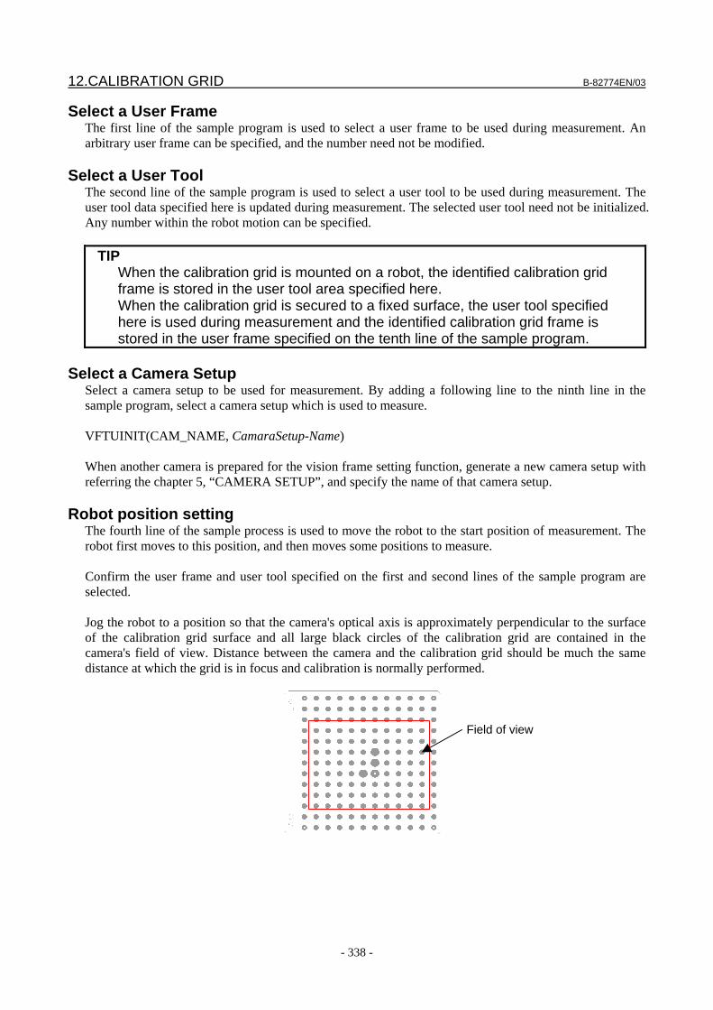
12.CALIBRATION GRID B-82774EN/03
- 338 -
Select a User Frame The first line of the sample program is used to select a user frame to be used during measurement. An arbitrary user frame can be specified, and the number need not be modified.
Select a User Tool The second line of the sample program is used to select a user tool to be used during measurement. The user tool data specified here is updated during measurement. The selected user tool need not be initialized. Any number within the robot motion can be specified.
TIP When the calibration grid is mounted on a robot, the identified calibration grid
frame is stored in the user tool area specified here. When the calibration grid is secured to a fixed surface, the user tool specified here is used during measurement and the identified calibration grid frame is stored in the user frame specified on the tenth line of the sample program.
Select a Camera Setup
Select a camera setup to be used for measurement. By adding a following line to the ninth line in the sample program, select a camera setup which is used to measure. VFTUINIT(CAM_NAME, CamaraSetup-Name) When another camera is prepared for the vision frame setting function, generate a new camera setup with referring the chapter 5, “CAMERA SETUP”, and specify the name of that camera setup.
Robot position setting The fourth line of the sample process is used to move the robot to the start position of measurement. The robot first moves to this position, and then moves some positions to measure. Confirm the user frame and user tool specified on the first and second lines of the sample program are selected. Jog the robot to a position so that the camera's optical axis is approximately perpendicular to the surface of the calibration grid surface and all large black circles of the calibration grid are contained in the camera's field of view. Distance between the camera and the calibration grid should be much the same distance at which the grid is in focus and calibration is normally performed.
Field of view
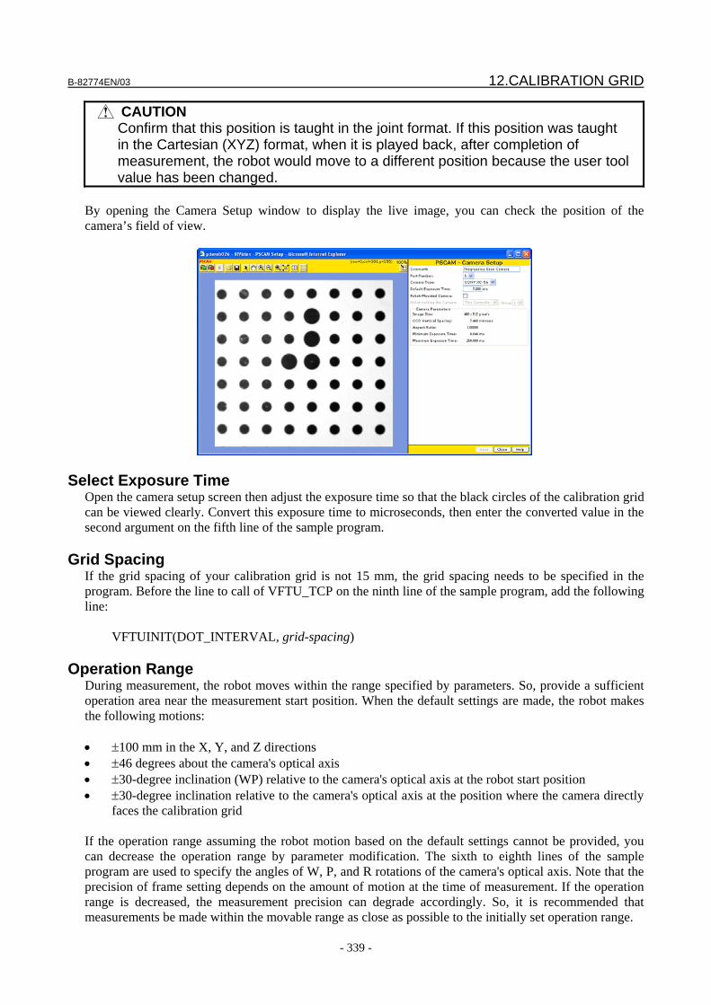
B-82774EN/03 12.CALIBRATION GRID
- 339 -
CAUTION Confirm that this position is taught in the joint format. If this position was taught
in the Cartesian (XYZ) format, when it is played back, after completion of measurement, the robot would move to a different position because the user tool value has been changed.
By opening the Camera Setup window to display the live image, you can check the position of the camera’s field of view.
Select Exposure Time Open the camera setup screen then adjust the exposure time so that the black circles of the calibration grid can be viewed clearly. Convert this exposure time to microseconds, then enter the converted value in the second argument on the fifth line of the sample program.
Grid Spacing If the grid spacing of your calibration grid is not 15 mm, the grid spacing needs to be specified in the program. Before the line to call of VFTU_TCP on the ninth line of the sample program, add the following line: VFTUINIT(DOT_INTERVAL, grid-spacing)
Operation Range During measurement, the robot moves within the range specified by parameters. So, provide a sufficient operation area near the measurement start position. When the default settings are made, the robot makes the following motions: • ±100 mm in the X, Y, and Z directions • ±46 degrees about the camera's optical axis • ±30-degree inclination (WP) relative to the camera's optical axis at the robot start position • ±30-degree inclination relative to the camera's optical axis at the position where the camera directly
faces the calibration grid If the operation range assuming the robot motion based on the default settings cannot be provided, you can decrease the operation range by parameter modification. The sixth to eighth lines of the sample program are used to specify the angles of W, P, and R rotations of the camera's optical axis. Note that the precision of frame setting depends on the amount of motion at the time of measurement. If the operation range is decreased, the measurement precision can degrade accordingly. So, it is recommended that measurements be made within the movable range as close as possible to the initially set operation range.
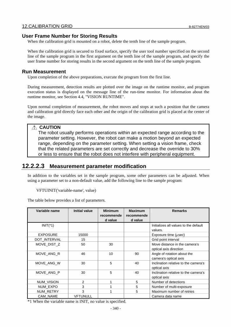
12.CALIBRATION GRID B-82774EN/03
- 340 -
User Frame Number for Storing Results When the calibration grid is mounted on a robot, delete the tenth line of the sample program. When the calibration grid is secured to fixed surface, specify the user tool number specified on the second line of the sample program in the first argument on the tenth line of the sample program, and specify the user frame number for storing results in the second argument on the tenth line of the sample program.
Run Measurement Upon completion of the above preparations, execute the program from the first line. During measurement, detection results are plotted over the image on the runtime monitor, and program execution status is displayed on the message line of the run-time monitor. For information about the runtime monitor, see Section 4.4, "VISION RUNTIME". Upon normal completion of measurement, the robot moves and stops at such a position that the camera and calibration grid directly face each other and the origin of the calibration grid is placed at the center of the image.
CAUTION The robot usually performs operations within an expected range according to the
parameter setting. However, the robot can make a motion beyond an expected range, depending on the parameter setting. When setting a vision frame, check that the related parameters are set correctly and decrease the override to 30% or less to ensure that the robot does not interfere with peripheral equipment.
12.2.2.3 Measurement parameter modification
In addition to the variables set in the sample program, some other parameters can be adjusted. When using a parameter set to a non-default value, add the following line to the sample program: VFTUINIT('variable-name', value) The table below provides a list of parameters.
Variable name Initial value Minimum recommende
d value
Maximum recommende
d value
Remarks
INIT(*1) Initializes all values to the default values.
EXPOSURE 15000 Exposure time (μsec) DOT_INTERVAL 15 Grid point interval MOVE_DIST_Z 50 30 Move distance in the camera’s
optical axis direction MOVE_ANG_R 46 10 90 Angle of rotation about the
camera's optical axis MOVE_ANG_W 30 5 40 Inclination relative to the camera's
optical axis MOVE_ANG_P 30 5 40 Inclination relative to the camera’s
optical axis NUM_VISION 2 1 5 Number of detections NUM_EXPO 3 1 5 Number of multi-exposure
NUM_RETRY 3 1 5 Maximum number of retries CAM_NAME VFTUNULL Camera data name
*1 When the variable name is INIT, no value is specified.
B-82774EN/03 12.CALIBRATION GRID
- 341 -
12.2.2.4 Troubleshooting
[CVIS-020 Big circles cannot be distinguished] is issued.
This error message is output when the four large black circles of the calibration grid could not be detected. Detection of large black circles failed because of an improper exposure time, or an object other than a grid point was detected. The run-time monitor screen displays the image output when a measurement failed. Check the image and adjust the shooting condition.
[CVIS-015 Too few calibration points] is issued. This error message is output when the number of grid points of the calibration grid detected during measurement is less than 4. Check whether the grid points are contained in the camera's visual field when the robot is placed at the measurement start position, whether the exposure time is proper, and whether the camera port number is correct. This error message is output also if a measurement is made when the camera is disabled for hardware trouble.
The program was terminated abnormally with an error. If an error occurs, the program is terminated forcibly. Modify the setting to enable correct measurement then execute the program from the beginning.
No image is displayed with the vision board. With the camera connected to the vision board, vision frame setting cannot be performed. To perform vision frame setting with a system using the vision board, modify the connection temporarily according to the following procedure: 1. Turn off the power to the robot controller. 2. Open the door of the controller then detach the vision board from the backplane. 3. Connect the camera to be used for measurement to the main board. 4. Close the door of the controller then turn on the power to the controller.
CAUTION After execution of the vision frame setting function, remember turn off the power
supply of the robot controller and restore the connection of a camera its original port.
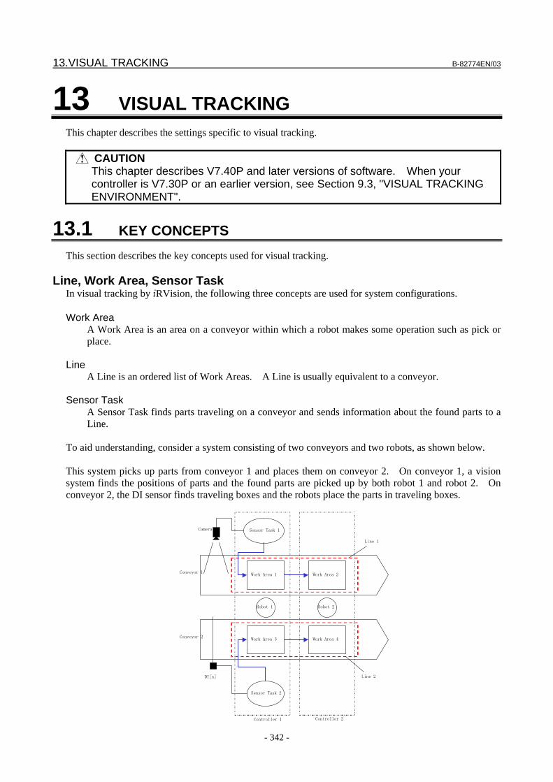
13.VISUAL TRACKING B-82774EN/03
- 342 -
13 VISUAL TRACKING This chapter describes the settings specific to visual tracking.
CAUTION This chapter describes V7.40P and later versions of software. When your
controller is V7.30P or an earlier version, see Section 9.3, "VISUAL TRACKING ENVIRONMENT".
13.1 KEY CONCEPTS This section describes the key concepts used for visual tracking.
Line, Work Area, Sensor Task In visual tracking by iRVision, the following three concepts are used for system configurations. Work Area
A Work Area is an area on a conveyor within which a robot makes some operation such as pick or place.
Line
A Line is an ordered list of Work Areas. A Line is usually equivalent to a conveyor. Sensor Task
A Sensor Task finds parts traveling on a conveyor and sends information about the found parts to a Line.
To aid understanding, consider a system consisting of two conveyors and two robots, as shown below. This system picks up parts from conveyor 1 and places them on conveyor 2. On conveyor 1, a vision system finds the positions of parts and the found parts are picked up by both robot 1 and robot 2. On conveyor 2, the DI sensor finds traveling boxes and the robots place the parts in traveling boxes.
Conveyor 1
Conveyor 2
Line 1
Line 2
Robot 1 Robot 2
Camera
DI [n] Sensor Task 2
Sensor Task 1
Work Area 3
Work Area 1 Work Area 2
Work Area 4
Controller 2Controller 1
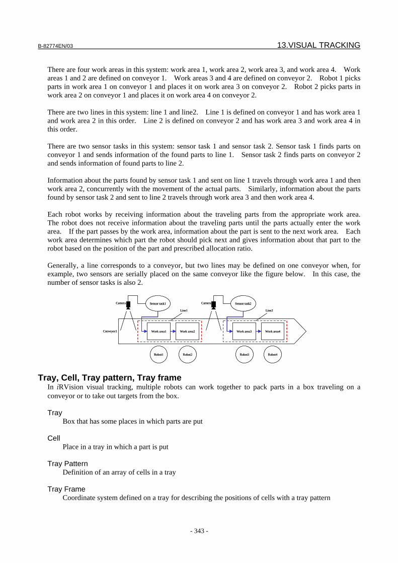
B-82774EN/03 13.VISUAL TRACKING
- 343 -
There are four work areas in this system: work area 1, work area 2, work area 3, and work area 4. Work areas 1 and 2 are defined on conveyor 1. Work areas 3 and 4 are defined on conveyor 2. Robot 1 picks parts in work area 1 on conveyor 1 and places it on work area 3 on conveyor 2. Robot 2 picks parts in work area 2 on conveyor 1 and places it on work area 4 on conveyor 2. There are two lines in this system: line 1 and line2. Line 1 is defined on conveyor 1 and has work area 1 and work area 2 in this order. Line 2 is defined on conveyor 2 and has work area 3 and work area 4 in this order. There are two sensor tasks in this system: sensor task 1 and sensor task 2. Sensor task 1 finds parts on conveyor 1 and sends information of the found parts to line 1. Sensor task 2 finds parts on conveyor 2 and sends information of found parts to line 2. Information about the parts found by sensor task 1 and sent on line 1 travels through work area 1 and then work area 2, concurrently with the movement of the actual parts. Similarly, information about the parts found by sensor task 2 and sent to line 2 travels through work area 3 and then work area 4. Each robot works by receiving information about the traveling parts from the appropriate work area. The robot does not receive information about the traveling parts until the parts actually enter the work area. If the part passes by the work area, information about the part is sent to the next work area. Each work area determines which part the robot should pick next and gives information about that part to the robot based on the position of the part and prescribed allocation ratio. Generally, a line corresponds to a conveyor, but two lines may be defined on one conveyor when, for example, two sensors are serially placed on the same conveyor like the figure below. In this case, the number of sensor tasks is also 2.
Conveyor1
Line1
Robot1
Camera Sensor task1
Work area1
Line2
Robot3
Camera Sensor task2
Work area3Work area2 Work area4
Robot2 Robot4
Conveyor1
Line1
Robot1
Camera Sensor task1
Work area1
Line2
Robot3
Camera Sensor task2
Work area3Work area2 Work area4
Robot2 Robot4
Tray, Cell, Tray pattern, Tray frame In iRVision visual tracking, multiple robots can work together to pack parts in a box traveling on a conveyor or to take out targets from the box. Tray
Box that has some places in which parts are put Cell
Place in a tray in which a part is put Tray Pattern
Definition of an array of cells in a tray Tray Frame
Coordinate system defined on a tray for describing the positions of cells with a tray pattern
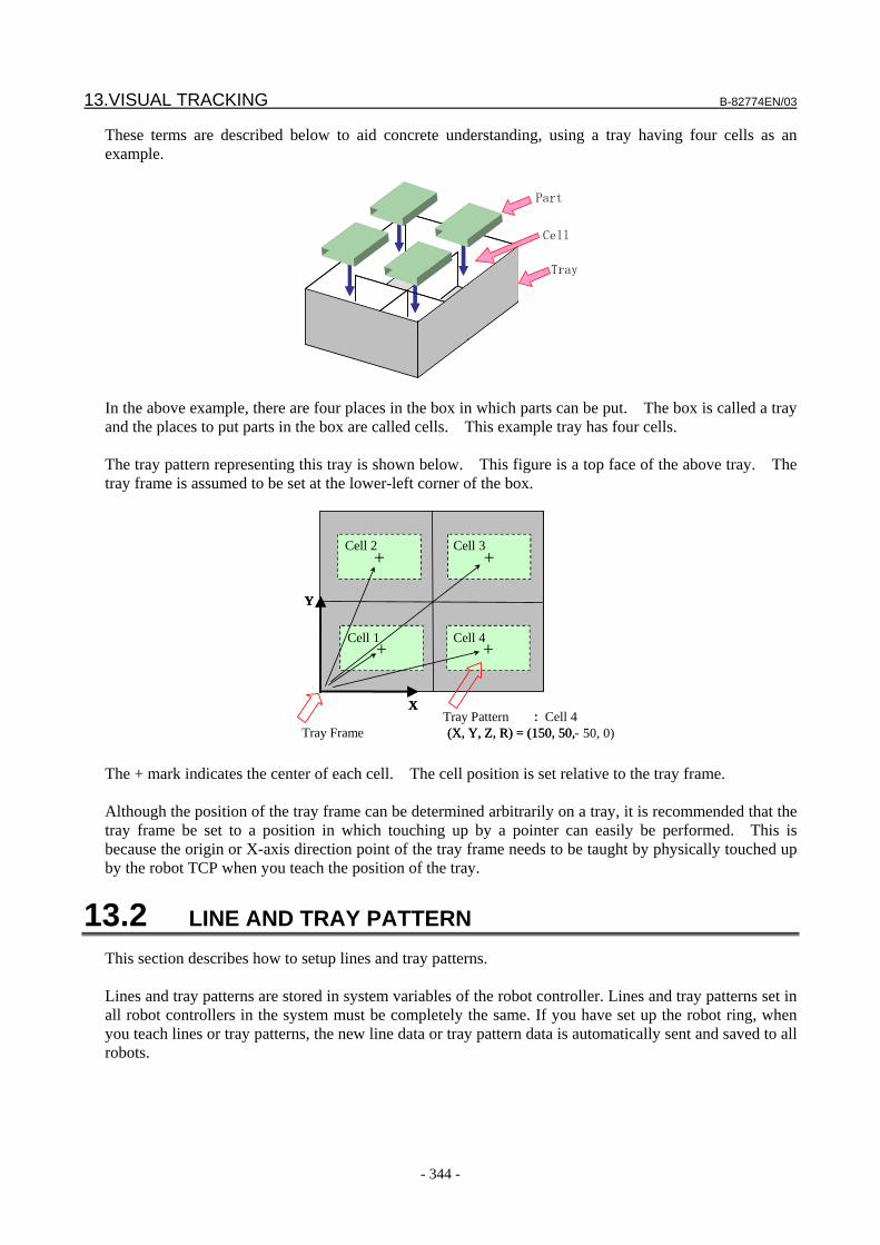
13.VISUAL TRACKING B-82774EN/03
- 344 -
These terms are described below to aid concrete understanding, using a tray having four cells as an example.
Cell
Part
Tray
In the above example, there are four places in the box in which parts can be put. The box is called a tray and the places to put parts in the box are called cells. This example tray has four cells. The tray pattern representing this tray is shown below. This figure is a top face of the above tray. The tray frame is assumed to be set at the lower-left corner of the box.
Tray Pattern : (X, Y, Z, R) = (150, 50, - 50, 0)
+ +
++
Y
X
セル1
セル2
セル4
セル
Tray Frame : Cell 4
(X, Y, Z, R) = (150, 50,
+ +
++
Y
X
Cell 1
Cell 2
Cell 4
Cell 3
The + mark indicates the center of each cell. The cell position is set relative to the tray frame. Although the position of the tray frame can be determined arbitrarily on a tray, it is recommended that the tray frame be set to a position in which touching up by a pointer can easily be performed. This is because the origin or X-axis direction point of the tray frame needs to be taught by physically touched up by the robot TCP when you teach the position of the tray.
13.2 LINE AND TRAY PATTERN This section describes how to setup lines and tray patterns. Lines and tray patterns are stored in system variables of the robot controller. Lines and tray patterns set in all robot controllers in the system must be completely the same. If you have set up the robot ring, when you teach lines or tray patterns, the new line data or tray pattern data is automatically sent and saved to all robots.

B-82774EN/03 13.VISUAL TRACKING
- 345 -
CAUTION If more than one controller is in the system make sure all controllers are
powered up when changing line or tray pattern data. Click [Visual Tracking Config] in the iRVision main setup page.
TIP Creating or adjusting a line and a tray pattern can be done from any robot
controller on the robot ring which iRVision is installed Simultaneously editing the line and tray pattern from two robot controllers is not allowed. Note that setting vision data such as camera setup, camera calibration and vision process can only be done from the robot controller in which the camera is installed.
Synchronize Lines and Tray Patterns among controllers
If a controller is powered off in the system when you teach or modify a line or a tray pattern, the data will be inconsistent among controllers. In such a case, after all robot controllers in the system are powered on, you can transfer line and tray pattern data on a controller to the others so that all controllers have the same setting of lines and tray patterns. Use the following procedure. Click button. After you are asked whether you are sure to transfer the setting to all controllers, click [OK]. By this operation, the line and tray pattern data in the robot controller in which iRVision operates are copied to all robot controllers in the system.
13.2.1 Setting a Line When a line is opened, a screen as shown below appears.
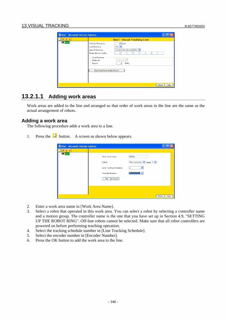
13.VISUAL TRACKING B-82774EN/03
- 346 -
13.2.1.1 Adding work areas Work areas are added to the line and arranged so that order of work areas in the line are the same as the actual arrangement of robots.
Adding a work area The following procedure adds a work area to a line. 1. Press the button. A screen as shown below appears.
2. Enter a work area name in [Work Area Name]. 3. Select a robot that operated in this work area. You can select a robot by selecting a controller name
and a motion group. The controller name is the one that you have set up in Section 4.9, "SETTING UP THE ROBOT RING". Off-line robots cannot be selected. Make sure that all robot controllers are powered on before performing teaching operation.
4. Select the tracking schedule number in [Line Tracking Schedule]. 5. Select the encoder number in [Encoder Number]. 6. Press the OK button to add the work area to the line.
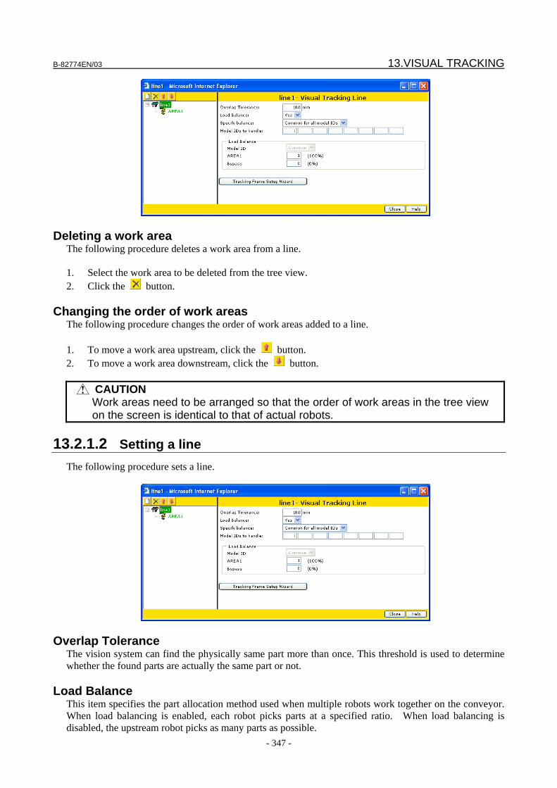
B-82774EN/03 13.VISUAL TRACKING
- 347 -
Deleting a work area The following procedure deletes a work area from a line. 1. Select the work area to be deleted from the tree view. 2. Click the button.
Changing the order of work areas The following procedure changes the order of work areas added to a line. 1. To move a work area upstream, click the button. 2. To move a work area downstream, click the button.
CAUTION Work areas need to be arranged so that the order of work areas in the tree view
on the screen is identical to that of actual robots.
13.2.1.2 Setting a line The following procedure sets a line.
Overlap Tolerance The vision system can find the physically same part more than once. This threshold is used to determine whether the found parts are actually the same part or not.
Load Balance This item specifies the part allocation method used when multiple robots work together on the conveyor. When load balancing is enabled, each robot picks parts at a specified ratio. When load balancing is disabled, the upstream robot picks as many parts as possible.
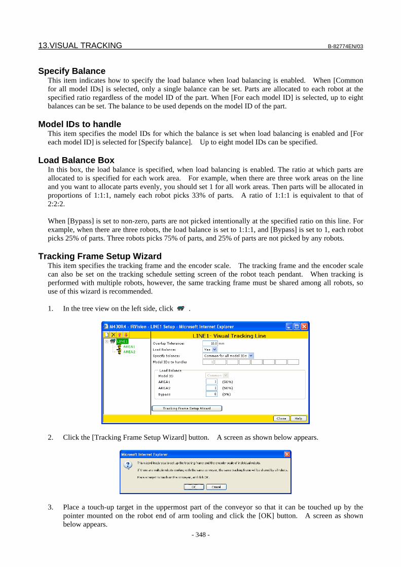
13.VISUAL TRACKING B-82774EN/03
- 348 -
Specify Balance
This item indicates how to specify the load balance when load balancing is enabled. When [Common for all model IDs] is selected, only a single balance can be set. Parts are allocated to each robot at the specified ratio regardless of the model ID of the part. When [For each model ID] is selected, up to eight balances can be set. The balance to be used depends on the model ID of the part.
Model IDs to handle This item specifies the model IDs for which the balance is set when load balancing is enabled and [For each model ID] is selected for [Specify balance]. Up to eight model IDs can be specified.
Load Balance Box In this box, the load balance is specified, when load balancing is enabled. The ratio at which parts are allocated to is specified for each work area. For example, when there are three work areas on the line and you want to allocate parts evenly, you should set 1 for all work areas. Then parts will be allocated in proportions of 1:1:1, namely each robot picks 33% of parts. A ratio of 1:1:1 is equivalent to that of 2:2:2. When [Bypass] is set to non-zero, parts are not picked intentionally at the specified ratio on this line. For example, when there are three robots, the load balance is set to 1:1:1, and [Bypass] is set to 1, each robot picks 25% of parts. Three robots picks 75% of parts, and 25% of parts are not picked by any robots.
Tracking Frame Setup Wizard This item specifies the tracking frame and the encoder scale. The tracking frame and the encoder scale can also be set on the tracking schedule setting screen of the robot teach pendant. When tracking is performed with multiple robots, however, the same tracking frame must be shared among all robots, so use of this wizard is recommended. 1. In the tree view on the left side, click .
2. Click the [Tracking Frame Setup Wizard] button. A screen as shown below appears.
3. Place a touch-up target in the uppermost part of the conveyor so that it can be touched up by the pointer mounted on the robot end of arm tooling and click the [OK] button. A screen as shown below appears.
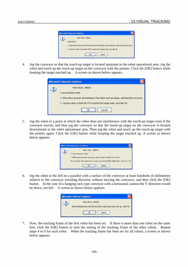
B-82774EN/03 13.VISUAL TRACKING
- 349 -
4. Jog the conveyor so that the touch-up target is located upstream in the robot operational area. Jog the
robot and touch up the touch-up target on the conveyor with the pointer. Click the [OK] button while keeping the target touched up. A screen as shown below appears.
5. Jog the robot to a point at which the robot does not interference with the touch-up target even if the
conveyor travels, and then jog the conveyor so that the touch-up target on the conveyor is located downstream in the robot operational area. Then jog the robot and touch up the touch-up target with the pointer again. Click the [OK] button while keeping the target touched up. A screen as shown below appears.
6. Jog the robot to the left on a parallel with a surface of the conveyor at least hundreds of millimeters
relative to the conveyor traveling direction without moving the conveyor, and then click the [OK] button. In the case of a hanging rack type conveyor with a horizontal camera the Y direction would be down, not left. A screen as shown below appears.
7. Now, the tracking frame of the first robot has been set. If there is more than one robot on the same
line, click the [OK] button to start the setting of the tracking frame of the other robots. Repeat steps 4 to 6 for each robot. When the tracking frame has been set for all robots, a screen as shown below appears.
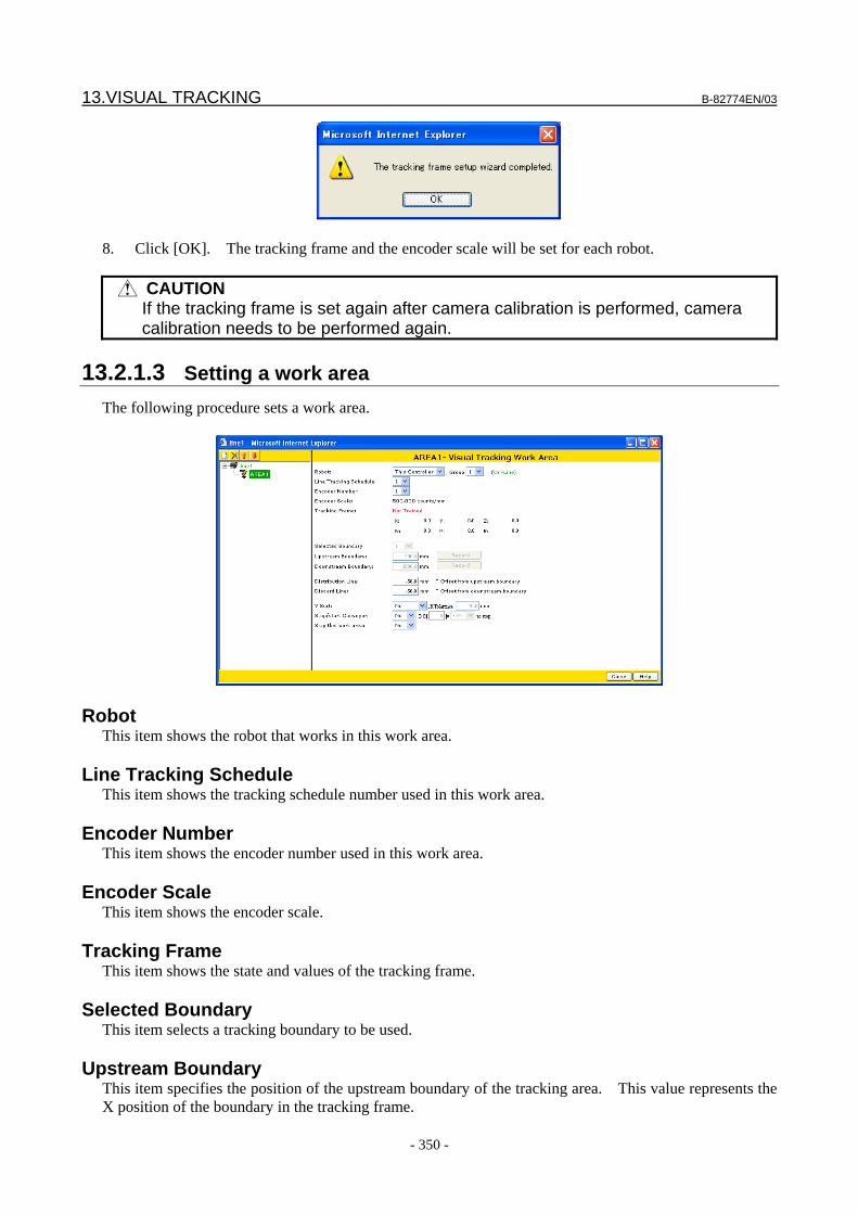
13.VISUAL TRACKING B-82774EN/03
- 350 -
8. Click [OK]. The tracking frame and the encoder scale will be set for each robot.
CAUTION If the tracking frame is set again after camera calibration is performed, camera
calibration needs to be performed again.
13.2.1.3 Setting a work area The following procedure sets a work area.
Robot This item shows the robot that works in this work area.
Line Tracking Schedule This item shows the tracking schedule number used in this work area.
Encoder Number This item shows the encoder number used in this work area.
Encoder Scale This item shows the encoder scale.
Tracking Frame This item shows the state and values of the tracking frame.
Selected Boundary This item selects a tracking boundary to be used.
Upstream Boundary This item specifies the position of the upstream boundary of the tracking area. This value represents the X position of the boundary in the tracking frame.
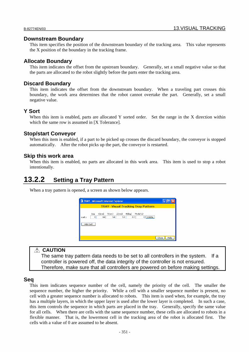
B-82774EN/03 13.VISUAL TRACKING
- 351 -
Downstream Boundary This item specifies the position of the downstream boundary of the tracking area. This value represents the X position of the boundary in the tracking frame.
Allocate Boundary This item indicates the offset from the upstream boundary. Generally, set a small negative value so that the parts are allocated to the robot slightly before the parts enter the tracking area.
Discard Boundary This item indicates the offset from the downstream boundary. When a traveling part crosses this boundary, the work area determines that the robot cannot overtake the part. Generally, set a small negative value.
Y Sort When this item is enabled, parts are allocated Y sorted order. Set the range in the X direction within which the same row is assumed in [X Tolerance].
Stop/start Conveyor When this item is enabled, if a part to be picked up crosses the discard boundary, the conveyor is stopped automatically. After the robot picks up the part, the conveyor is restarted.
Skip this work area When this item is enabled, no parts are allocated in this work area. This item is used to stop a robot intentionally.
13.2.2 Setting a Tray Pattern When a tray pattern is opened, a screen as shown below appears.
CAUTION The same tray pattern data needs to be set to all controllers in the system. If a
controller is powered off, the data integrity of the controller is not ensured. Therefore, make sure that all controllers are powered on before making settings.
Seq
This item indicates sequence number of the cell, namely the priority of the cell. The smaller the sequence number, the higher the priority. While a cell with a smaller sequence number is present, no cell with a greater sequence number is allocated to robots. This item is used when, for example, the tray has a multiple layers, in which the upper layer is used after the lower layer is completed. In such a case, this item controls the sequence in which parts are placed in the tray. Generally, specify the same value for all cells. When there are cells with the same sequence number, these cells are allocated to robots in a flexible manner. That is, the lowermost cell in the tracking area of the robot is allocated first. The cells with a value of 0 are assumed to be absent.
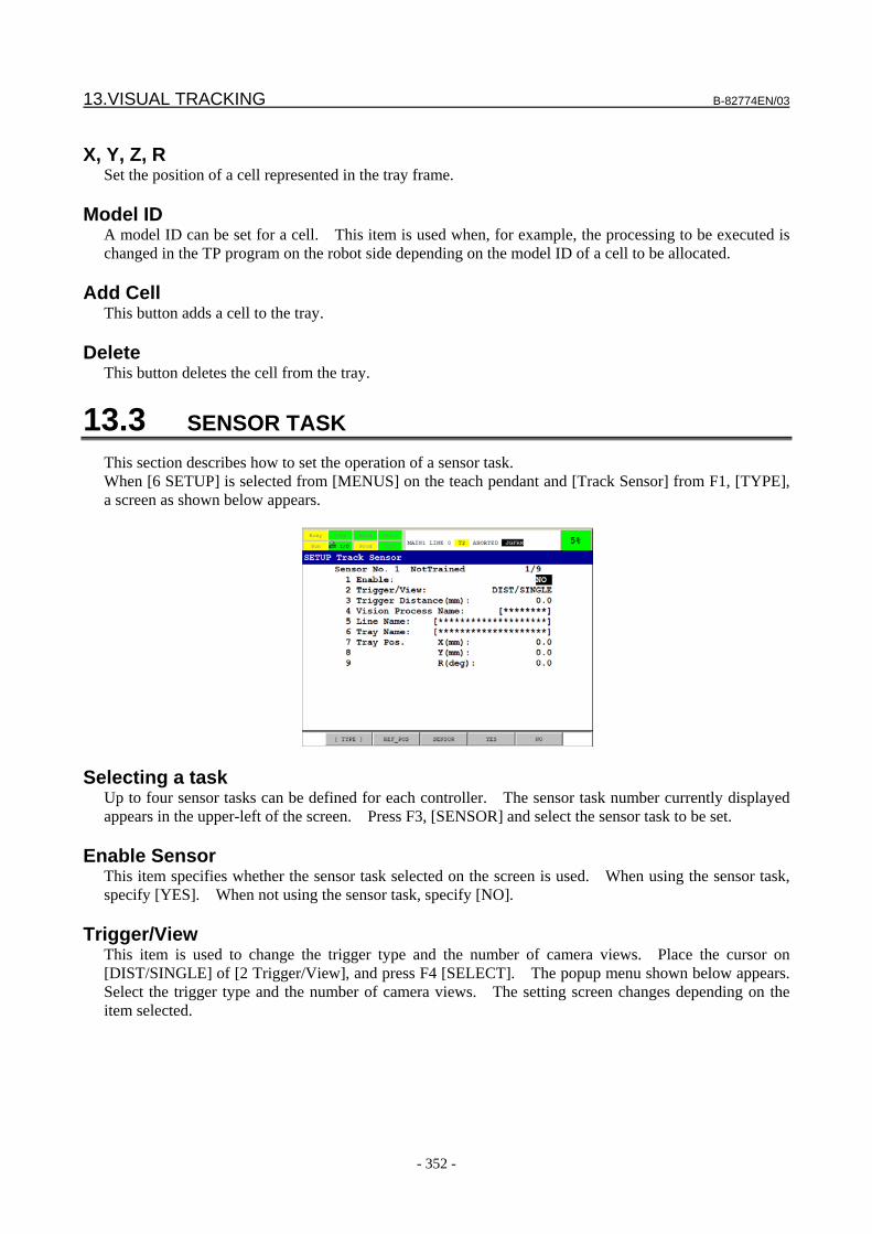
13.VISUAL TRACKING B-82774EN/03
- 352 -
X, Y, Z, R
Set the position of a cell represented in the tray frame.
Model ID A model ID can be set for a cell. This item is used when, for example, the processing to be executed is changed in the TP program on the robot side depending on the model ID of a cell to be allocated.
Add Cell This button adds a cell to the tray.
Delete This button deletes the cell from the tray.
13.3 SENSOR TASK This section describes how to set the operation of a sensor task. When [6 SETUP] is selected from [MENUS] on the teach pendant and [Track Sensor] from F1, [TYPE], a screen as shown below appears.
Selecting a task Up to four sensor tasks can be defined for each controller. The sensor task number currently displayed appears in the upper-left of the screen. Press F3, [SENSOR] and select the sensor task to be set.
Enable Sensor This item specifies whether the sensor task selected on the screen is used. When using the sensor task, specify [YES]. When not using the sensor task, specify [NO].
Trigger/View This item is used to change the trigger type and the number of camera views. Place the cursor on [DIST/SINGLE] of [2 Trigger/View], and press F4 [SELECT]. The popup menu shown below appears. Select the trigger type and the number of camera views. The setting screen changes depending on the item selected.

B-82774EN/03 13.VISUAL TRACKING
- 353 -
There are five options. DIST/SINGLE
Each time the conveyor moves the specified distance, a vision process is executed once to find parts traveling on the conveyor.
DI/NONE
A phototube sensor installed on the conveyor finds parts traveling on the conveyor. DI/SINGLE
Upon the input of a DI signal from a phototube sensor installed on the conveyor, a vision process is executed once to find parts traveling on the conveyor.
DI/DOUBLE
When the conveyor moves the specified distance after a DI signal is input from a phototube sensor installed on the conveyor, the first vision process is executed once. When the conveyor moves the specified distance again, the second vision process is executed once. The found results of the two vision processes are combined to calculate a part position. Use this option when handling a large part that cannot fit in a single camera's field of view.
HDI/NONE
A phototube sensor installed on the conveyor finds parts traveling on the conveyor. This option offers higher precision than the DI option but can be used only once per controller.
Trigger Distance (mm)
This item specifies the distance in mm that the conveyor moves before a vision process is executed.
Vision Process Name When using iRVision, enter the name of the vision process used in this sensor task.
Line Name This item specifies the name of the line to which information found parts by the sensor task is sent.
Tray Name This item specifies the name of a tray pattern when a traveling part is a tray.
When [DI/NONE] is selected as the [Trigger/View] In this case, the following screen appears.
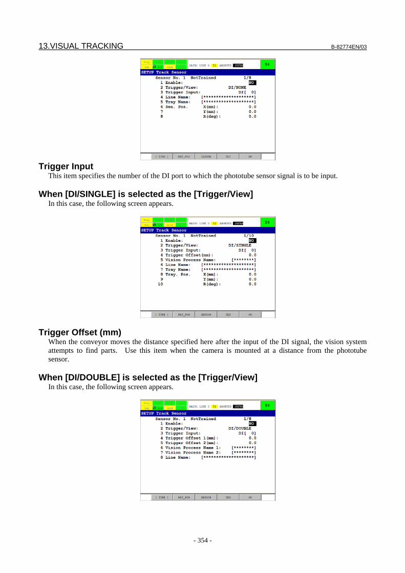
13.VISUAL TRACKING B-82774EN/03
- 354 -
Trigger Input
This item specifies the number of the DI port to which the phototube sensor signal is to be input.
When [DI/SINGLE] is selected as the [Trigger/View] In this case, the following screen appears.
Trigger Offset (mm) When the conveyor moves the distance specified here after the input of the DI signal, the vision system attempts to find parts. Use this item when the camera is mounted at a distance from the phototube sensor.
When [DI/DOUBLE] is selected as the [Trigger/View] In this case, the following screen appears.
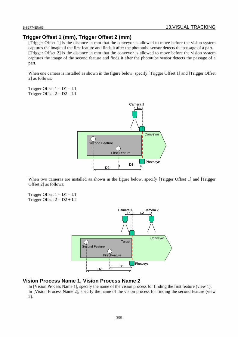
B-82774EN/03 13.VISUAL TRACKING
- 355 -
Trigger Offset 1 (mm), Trigger Offset 2 (mm) [Trigger Offset 1] is the distance in mm that the conveyor is allowed to move before the vision system captures the image of the first feature and finds it after the phototube sensor detects the passage of a part. [Trigger Offset 2] is the distance in mm that the conveyor is allowed to move before the vision system captures the image of the second feature and finds it after the phototube sensor detects the passage of a part. When one camera is installed as shown in the figure below, specify [Trigger Offset 1] and [Trigger Offset 2] as follows: Trigger Offset 1 = D1 – L1 Trigger Offset 2 = D2 – L1
Photoeye
L1
D1
Camera 1
D2
First Feature
Second Feature
Conveyor
Photoeye
L1
D1
Camera 1
D2
First Feature
Second Feature
Conveyor
When two cameras are installed as shown in the figure below, specify [Trigger Offset 1] and [Trigger Offset 2] as follows: Trigger Offset 1 = D1 – L1 Trigger Offset 2 = D2 + L2
L1 L2
D1
Camera 1
D2
Camera 2
Photoeye
Target
First Feature
Second Feature
Conveyor
L1 L2
D1
Camera 1
D2
Camera 2
Photoeye
Target
First Feature
Second Feature
Conveyor
Vision Process Name 1, Vision Process Name 2 In [Vision Process Name 1], specify the name of the vision process for finding the first feature (view 1). In [Vision Process Name 2], specify the name of the vision process for finding the second feature (view 2).
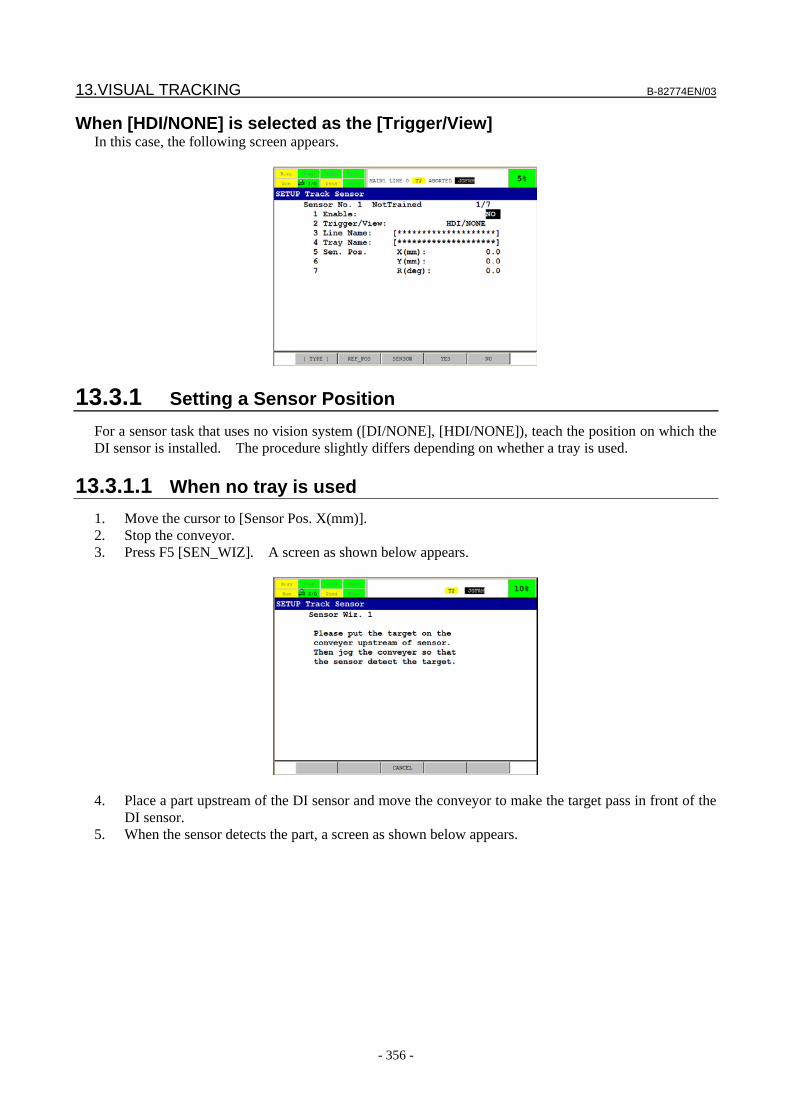
13.VISUAL TRACKING B-82774EN/03
- 356 -
When [HDI/NONE] is selected as the [Trigger/View] In this case, the following screen appears.
13.3.1 Setting a Sensor Position For a sensor task that uses no vision system ([DI/NONE], [HDI/NONE]), teach the position on which the DI sensor is installed. The procedure slightly differs depending on whether a tray is used.
13.3.1.1 When no tray is used 1. Move the cursor to [Sensor Pos. X(mm)]. 2. Stop the conveyor. 3. Press F5 [SEN_WIZ]. A screen as shown below appears.
4. Place a part upstream of the DI sensor and move the conveyor to make the target pass in front of the
DI sensor. 5. When the sensor detects the part, a screen as shown below appears.
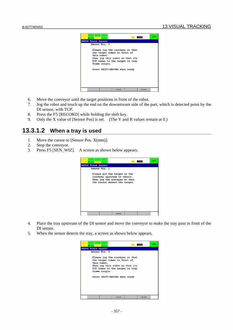
B-82774EN/03 13.VISUAL TRACKING
- 357 -
6. Move the conveyor until the target positions in front of the robot. 7. Jog the robot and touch up the end on the downstream side of the part, which is detected point by the
DI sensor, with TCP. 8. Press the F5 [RECORD] while holding the shift key. 9. Only the X value of [Sensor Pos] is set. (The Y and R values remain at 0.)
13.3.1.2 When a tray is used 1. Move the cursor to [Sensor Pos. X(mm)]. 2. Stop the conveyor. 3. Press F5 [SEN_WIZ]. A screen as shown below appears.
4. Place the tray upstream of the DI sensor and move the conveyor to make the tray pass in front of the
DI sensor. 5. When the sensor detects the tray, a screen as shown below appears.
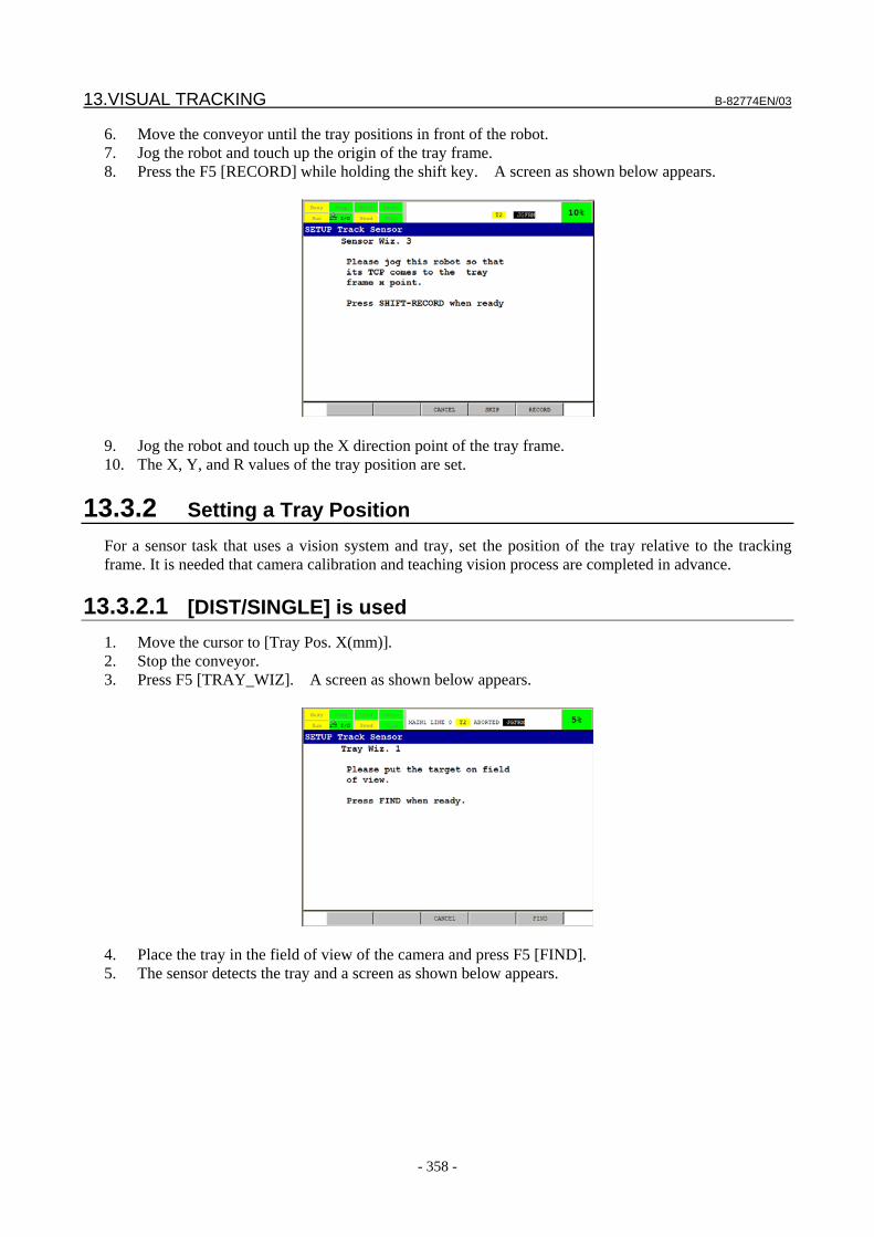
13.VISUAL TRACKING B-82774EN/03
- 358 -
6. Move the conveyor until the tray positions in front of the robot. 7. Jog the robot and touch up the origin of the tray frame. 8. Press the F5 [RECORD] while holding the shift key. A screen as shown below appears.
9. Jog the robot and touch up the X direction point of the tray frame. 10. The X, Y, and R values of the tray position are set.
13.3.2 Setting a Tray Position For a sensor task that uses a vision system and tray, set the position of the tray relative to the tracking frame. It is needed that camera calibration and teaching vision process are completed in advance.
13.3.2.1 [DIST/SINGLE] is used 1. Move the cursor to [Tray Pos. X(mm)]. 2. Stop the conveyor. 3. Press F5 [TRAY_WIZ]. A screen as shown below appears.
4. Place the tray in the field of view of the camera and press F5 [FIND]. 5. The sensor detects the tray and a screen as shown below appears.
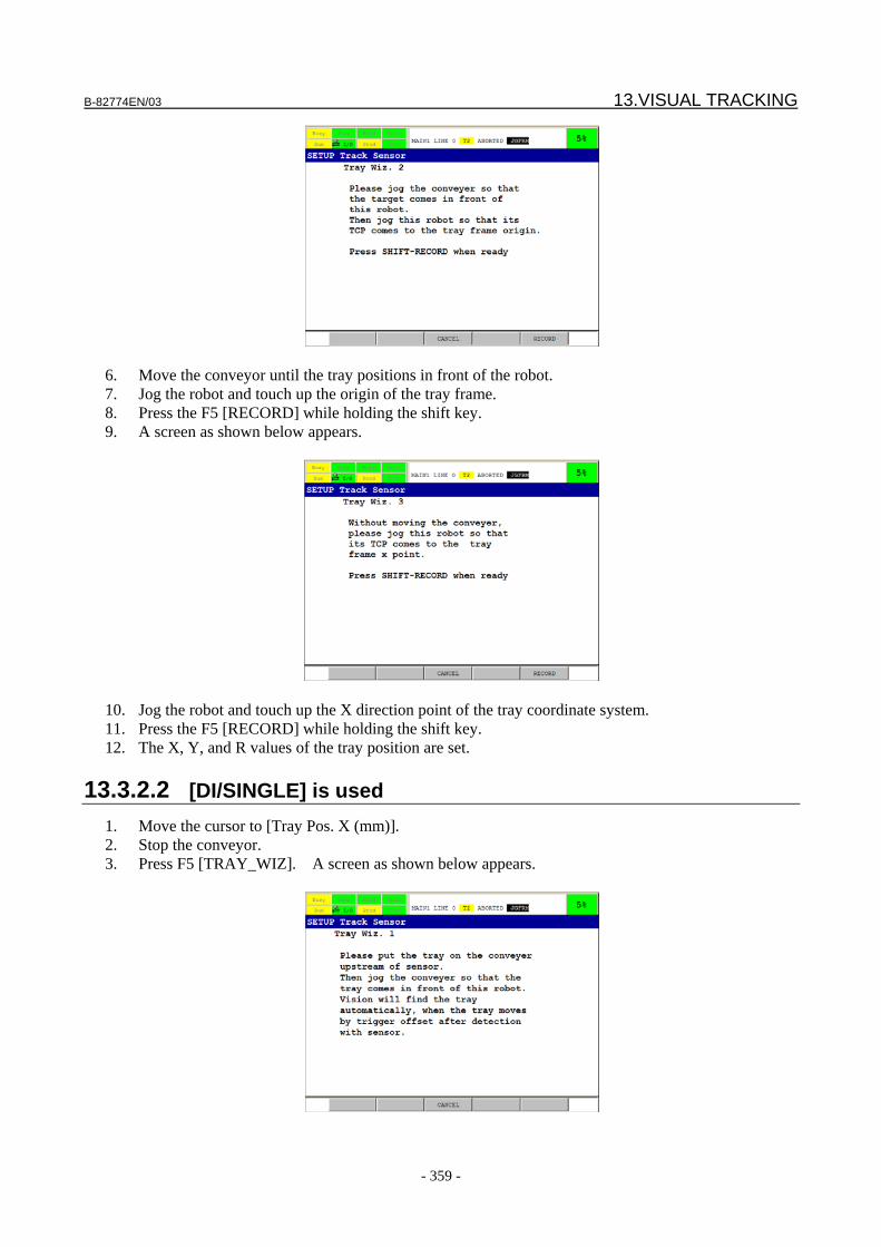
B-82774EN/03 13.VISUAL TRACKING
- 359 -
6. Move the conveyor until the tray positions in front of the robot. 7. Jog the robot and touch up the origin of the tray frame. 8. Press the F5 [RECORD] while holding the shift key. 9. A screen as shown below appears.
10. Jog the robot and touch up the X direction point of the tray coordinate system. 11. Press the F5 [RECORD] while holding the shift key. 12. The X, Y, and R values of the tray position are set.
13.3.2.2 [DI/SINGLE] is used 1. Move the cursor to [Tray Pos. X (mm)]. 2. Stop the conveyor. 3. Press F5 [TRAY_WIZ]. A screen as shown below appears.
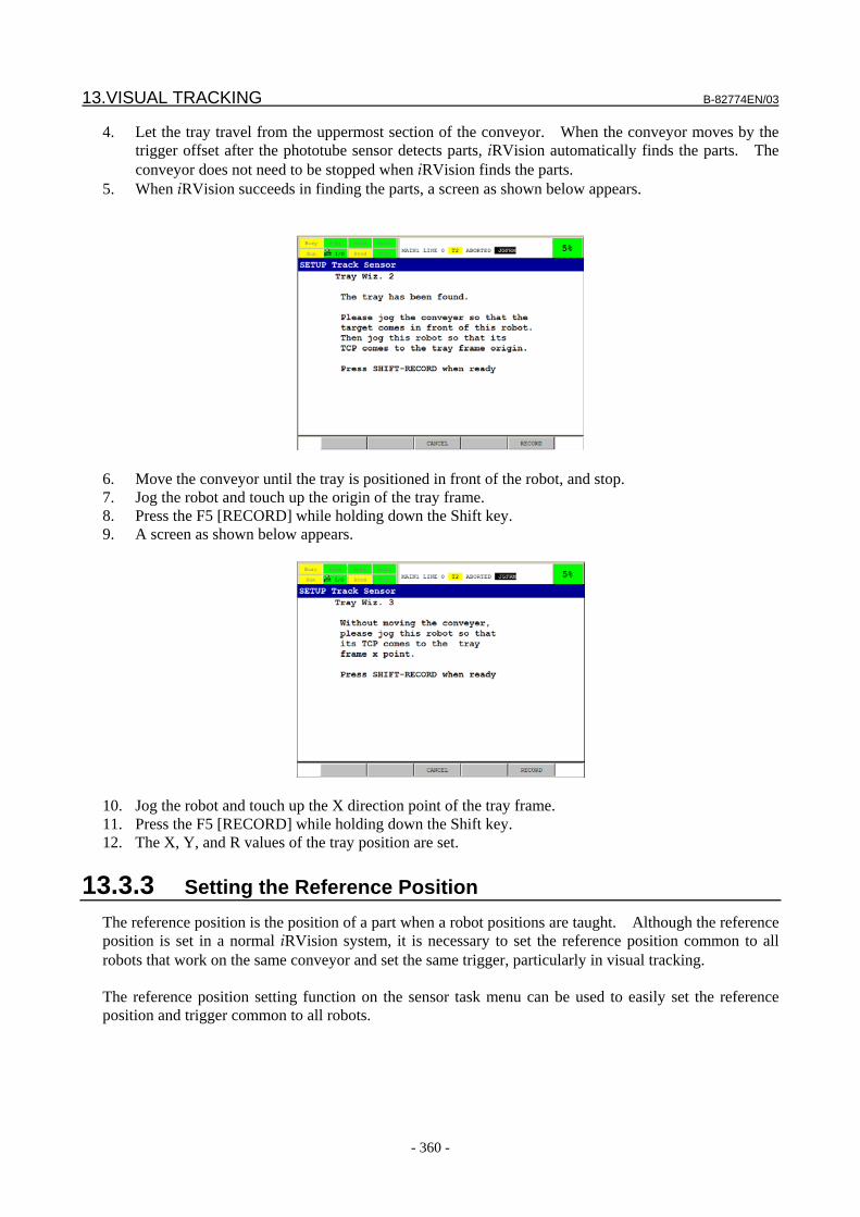
13.VISUAL TRACKING B-82774EN/03
- 360 -
4. Let the tray travel from the uppermost section of the conveyor. When the conveyor moves by the trigger offset after the phototube sensor detects parts, iRVision automatically finds the parts. The conveyor does not need to be stopped when iRVision finds the parts.
5. When iRVision succeeds in finding the parts, a screen as shown below appears.
6. Move the conveyor until the tray is positioned in front of the robot, and stop. 7. Jog the robot and touch up the origin of the tray frame. 8. Press the F5 [RECORD] while holding down the Shift key. 9. A screen as shown below appears.
10. Jog the robot and touch up the X direction point of the tray frame. 11. Press the F5 [RECORD] while holding down the Shift key. 12. The X, Y, and R values of the tray position are set.
13.3.3 Setting the Reference Position The reference position is the position of a part when a robot positions are taught. Although the reference position is set in a normal iRVision system, it is necessary to set the reference position common to all robots that work on the same conveyor and set the same trigger, particularly in visual tracking. The reference position setting function on the sensor task menu can be used to easily set the reference position and trigger common to all robots.
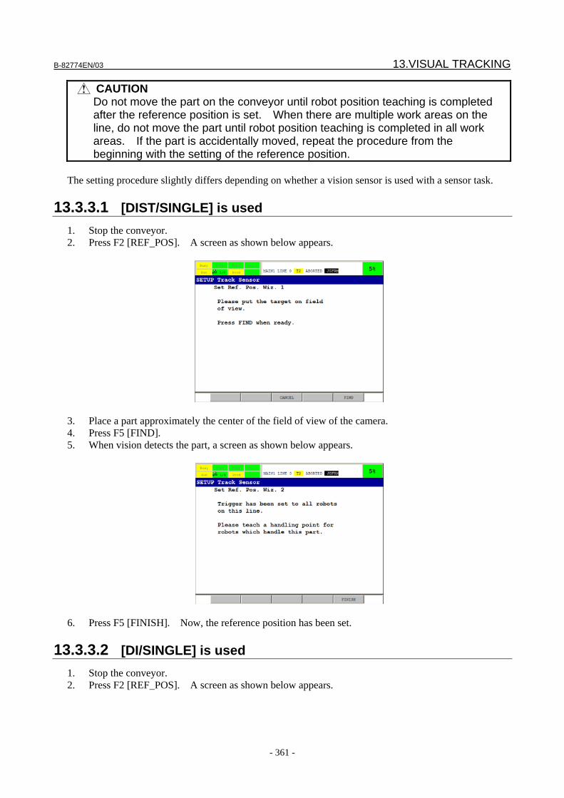
B-82774EN/03 13.VISUAL TRACKING
- 361 -
CAUTION Do not move the part on the conveyor until robot position teaching is completed
after the reference position is set. When there are multiple work areas on the line, do not move the part until robot position teaching is completed in all work areas. If the part is accidentally moved, repeat the procedure from the beginning with the setting of the reference position.
The setting procedure slightly differs depending on whether a vision sensor is used with a sensor task.
13.3.3.1 [DIST/SINGLE] is used 1. Stop the conveyor. 2. Press F2 [REF_POS]. A screen as shown below appears.
3. Place a part approximately the center of the field of view of the camera. 4. Press F5 [FIND]. 5. When vision detects the part, a screen as shown below appears.
6. Press F5 [FINISH]. Now, the reference position has been set.
13.3.3.2 [DI/SINGLE] is used 1. Stop the conveyor. 2. Press F2 [REF_POS]. A screen as shown below appears.

13.VISUAL TRACKING B-82774EN/03
- 362 -
3. Let the part travel from the uppermost section of the conveyor. When the conveyor moves by the
trigger offset after the phototube sensor detects the part, iRVision automatically finds the part. The conveyor does not need to be stopped when iRVision finds the part.
4. When iRVision succeeds in finding the part, a screen as shown below appears.
5. Press F5 [FINISH]. This completes the setting of the reference position.
13.3.3.3 [DI/DOUBLE] is used 1. Put the part on the upstream section of the conveyor ahead of the phototube sensor. 2. Press F2 [REF_POS] to start the reference position setting wizard. A screen as shown below
appears.
3. Move the conveyor so that the phototube sensor detects the part. 4. When the part travels the distance specified in [Trigger Offset 1] after the sensor succeeds in
detection, iRVision automatically attempts to find the first feature. When the feature is
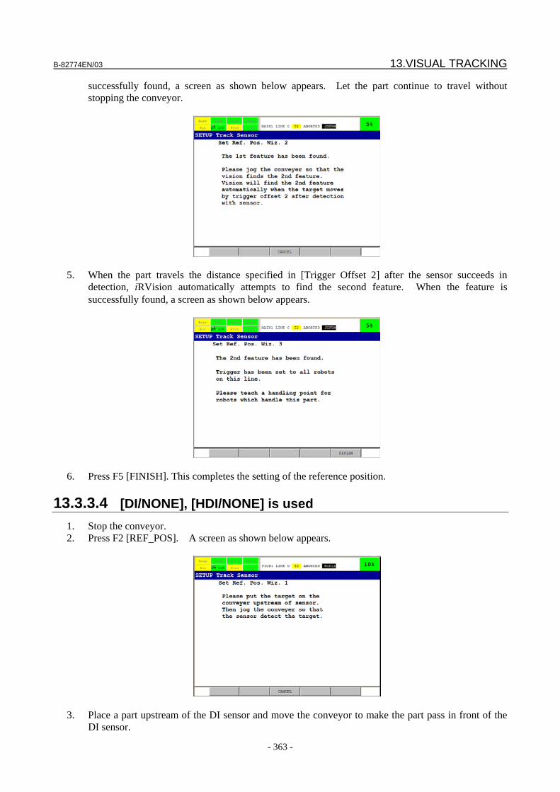
B-82774EN/03 13.VISUAL TRACKING
- 363 -
successfully found, a screen as shown below appears. Let the part continue to travel without stopping the conveyor.
5. When the part travels the distance specified in [Trigger Offset 2] after the sensor succeeds in
detection, iRVision automatically attempts to find the second feature. When the feature is successfully found, a screen as shown below appears.
6. Press F5 [FINISH]. This completes the setting of the reference position.
13.3.3.4 [DI/NONE], [HDI/NONE] is used 1. Stop the conveyor. 2. Press F2 [REF_POS]. A screen as shown below appears.
3. Place a part upstream of the DI sensor and move the conveyor to make the part pass in front of the
DI sensor.
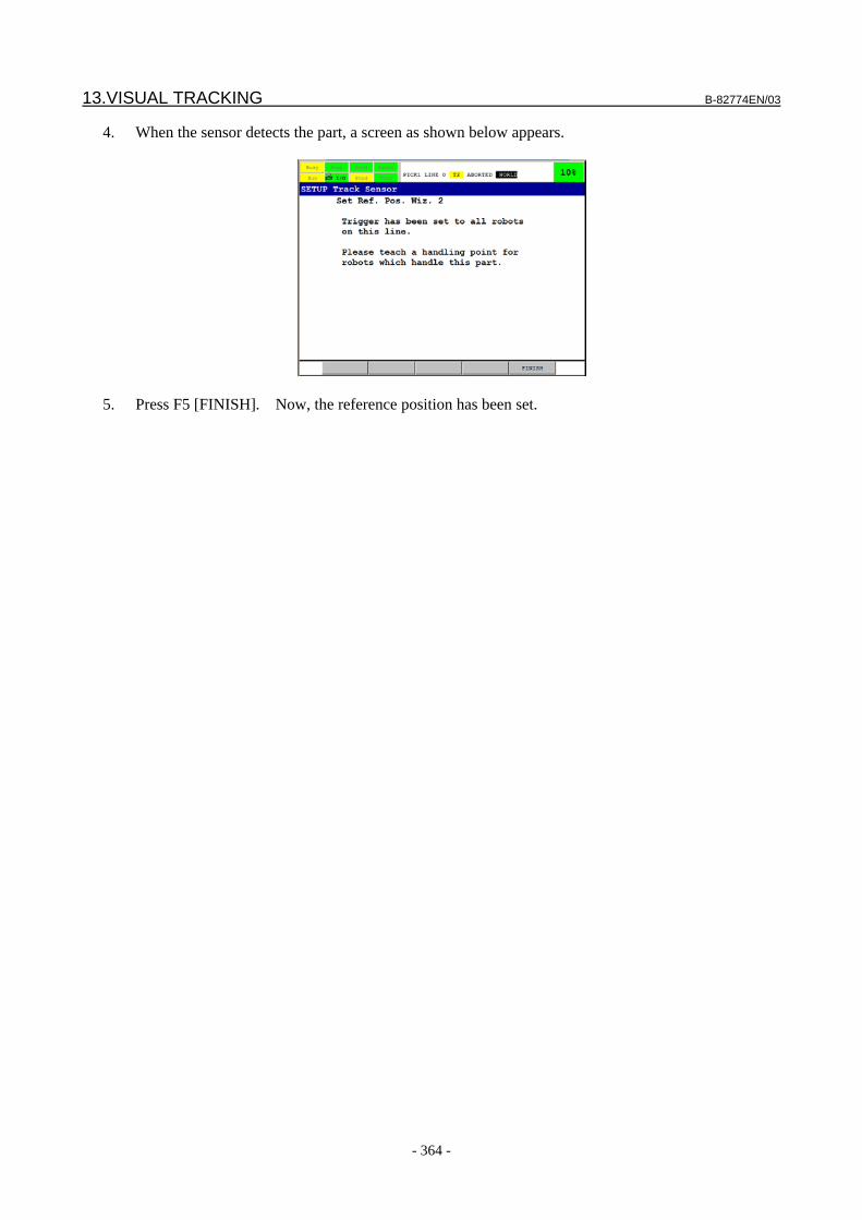
13.VISUAL TRACKING B-82774EN/03
- 364 -
4. When the sensor detects the part, a screen as shown below appears.
5. Press F5 [FINISH]. Now, the reference position has been set.
B-82774EN/03 14.VISION SUPPORT TOOLS
- 365 -
14 VISION SUPPORT TOOLS This chapter describes the vision support tools.
14.1 OVERVIEW The vision support tools are software options consisting of a set of tools intended to support an iRVision-based robot system. Using these options, you can have the corresponding KAREL programs installed to the controller and run those programs by means of the relevant call commands. Offset calculation
Special offset calculation mechanisms are provided that cannot be supported by the standard functions. OFS_RJ3, MATRIX, INVERSE, MERGE3D2, and STVS1
Saving and restoration of position register data
Functions to store and restore 1000 position registers' worth of data are provided. SAVENOM and LOADNOM
Offset adjustment A function is provided that allows the offset error to be adjusted with ease. ADJ_OFS Sorting of found results A function is provided that sorts found results. SORT_RJ3 Offset position checking A function is provided that checks whether the offset position is within the valid range of robot
motion. CHK_POS Inter-Controller Communication Functions are provided that enable register data and position register data to be sent and received
between controllers. SENDPREG, SENDREG, RECVPREG, RECVREG, CLRPREG, CLRREG
Restrictions • These functions are included in the vision support tool option. • To use these functions, be sure to set the system variable $KAREL_ENB to 1. • Inter-controller communication (SENDPREG, SENDREG, RECVPREG, RECVREG, CLRPREG,
or CLRREG) requires that the robots on both ends have the iRVision TPP interface option. • The position register formats that you can specify for these tools are the XYZWPR format, matrix
format, XYZWPR format with an additional axis, and matrix format with an additional axis. Position registers of the joint format are not supported. If the specified position register is of the joint format, an error occurs.
• If the position register specified by any of these tools has not been initialized (the value in the position register is ******), an error occurs.
14.VISION SUPPORT TOOLS B-82774EN/03
- 366 -
Behavior at the time of an error All the KAREL programs have an argument that specifies "the register number to store the error number". This argument can be omitted in most of the KAREL programs. How a KAREL program behaves if an error occurs during the execution of the program differs depending on whether "the regisrer number to store the error number" is specified or not. When "the register number to store the error number" is specified, 0 is stored in the specified register if the program ends normally. If an error occurs, the corresponding error code is stored in the specified register and an error message appears in the upper part of the teach pendant screen. If an error occurs when "the register number to store the error number" is omitted, the program is forced to end and the user screen displays a message describing the error. Note that this argument cannot be omitted in CHK_POS and STVS1.
14.2 OFS_RJ3 This program calculates offset data based on the found position and reference position stored in position registers. The robot can perform offset operations using the offset data calculated by OFS_RJ3. Since iRVision normally calculates offset data within the vision process, it is not necessary to use OFS_RJ3. Use this program when you need any offset mode that is not supported by vision processes. Argument 1:Register number Specify the number of the register storing a flag that indicates whether to set the reference position.
When 1 is set in the specified register, the found position will be set as the reference position in the position register specified by argument 4. When 0 is set, the reference position will not be set.
Argument 2:Position register number Specify the number of the position register storing the found position of the first camera. Argument 3:Position register number Specify the number of the position register storing the found position of the second camera. Argument 4:Position register number Specify the number of the position register that currently stores the reference position or that will
store the reference position. Argument 5:Position register number Specify the number of the position register to store the calculated fixed frame offset data of the
sensor A format. Argument 6:Position register number Specify the number of the position register to store the calculated fixed frame offset data of the
sensor B format. Argument 7:Position register number Specify the number of the position register to store the calculated tool offset data. Argument 8:Register number Specify the number of the position register to store the error number. This argument can be
omitted. In the register to store the error number, one of the values shown below will be set depending on the error that occurs: 0: The program ended normally.
B-82774EN/03 14.VISION SUPPORT TOOLS
- 367 -
501: A required argument is not specified. 502: An invalid argument is specified. 503: The nominal flag is invalid. 504: Data cannot be written to the specified register. 505: The format of the specified position register failed to be acquired. 506: The format of the specified position register is invalid. 507: The specified position register cannot be read. 508: The specified position register has not been initialized. 509: Offset data failed to be calculated (the two points are too close to each other). 510: Data cannot be written to the specified position register.
Usage example 1 This is an example where one camera is used to find a workpiece and fixed frame offsetting is performed for the robot according to the calculated offset data of the sensor A type. 11: CALL OFS_RJ3(P1,P2,0,P4,P5,0,0) 12: L P[1] 1000mm/sec FINE OFFSET,PR[P5]
Usage example 2
This is an example where one camera is used to find a workpiece and fixed frame offsetting is performed for the robot according to the calculated offset data of the sensor B type (the offset data of the sensor A type is referenced). Since fixed frame offsetting is performed using the sensor B format, the format of the position register used for the fixed frame offset command is converted to the matrix format, by copying the offset data to the user frame and then copying it back to the position register. 11: CALL OFS_RJ3(P1,P2,0,P4,P5,P6,0) 12: UFRAME[9]=PR[P6] 13: PR[n]=UFRAME[9] 14: L P[1] 1000mm/sec FINE OFFSET,PR [n]
Usage example 3
This is an example where one camera is used to find a workpiece and fixed frame offsetting is performed for the robot according to the offset data of the sensor B type (the offset data of the sensor A type is not referenced). Since fixed frame offsetting is performed using the sensor B format, the format of the position register used for the fixed frame offset command is converted to the matrix format, by copying the offset data to the user frame and then copying it back to the position register. 11: CALL OFS_RJ3(P1,P2,0,P4,0,P6,0) 12: UFRAME [9]=PR[P6] 13: PR[n]= UFRAME [9] 14: L P[1] 1000mm/sec FINE OFFSET,PR[n]
Usage example 4
This is an example where one camera is used to find a workpiece and tool offsetting is performed for the robot. 11: CALL OFS_RJ3(P1,P2,0,P4,0,0,P7) 12: UFRAME[9]=PR[P7] 13: PR[n]=UFRAME[9] 14: L P[1] 1000mm/sec FINE TOOL_OFFSET,PR[n]
Usage example 5
This is an example where two cameras are used to find one workpiece, or one hand camera is used to find two positions on one workpiece, to perform fixed frame offsetting for the robot (offset data of the sensor
14.VISION SUPPORT TOOLS B-82774EN/03
- 368 -
A type). The two found positions are merged to generate one set of position data. Found positions that can be input are the 2D data of X, Y, and R. The merged position data are also the 2D data of X, Y, and R. X, Y, and R in the merged position data represent an intermediate point between the two positions. To generate 3D data, use MERGE3D2. 11: CALL OFS_RJ3(P1,P2,P3,P4,P5,0,0) 12: L PR[1] 1000mm/sec FINE OFFSET,PR[P5]
Usage example 6
This is an example where two cameras are used to find one workpiece, or one hand camera is used to find two positions on one workpiece, to perform fixed frame offsetting for the robot (offset data of the sensor B type). The two found positions are merged to generate one set of position data. Found positions that can be input are the 2D data of X, Y, and R. The merged position data are also the 2D data of X, Y, and R. X, Y, and R in the merged position data represent an intermediate point between the two positions. To generate 3D data, use MERGE3D2. 11: CALL OFS_RJ3(P1,P2,P3,P4,0,P6,0) 12: UFRAME[9]=PR[P6] 13: PR[n]=UFRAME[9] 14: L P[1] 1000mm/sec FINE OFFSET,PR[n]
Usage example 7
This is an example where two cameras are used to find one workpiece, or one hand camera is used to find two positions on one workpiece, to perform tool offsetting for the robot. The two found positions are merged to generate one set of position data. Found positions that can be input are the 2D data of X, Y, and R. The merged position data are also the 2D data of X, Y, and R. X, Y, and R in the merged position data represent an intermediate point between the two positions. To generate 3D data, use MERGE3D2. 11: CALL OFS_RJ3(P1,P2,P3,P4,0,0,P7) 12: UFRAME[9]=PR[P7] 13: PR[n]=UFRAME[9] 14: L P[1] 1000mm/sec FINE TOOL_OFFSET,PR[n]
14.3 MATRIX This program regards the position register values given in the XYZWPR or matrix format as a homogeneous transform matrix and calculates the product of that matrix. When the input matrixes are A and B and the output matrix is C, the program calculates the equation C = AB. Argument 1:Position register number Specify the number of the position register storing input matrix A. Argument 2:Position register number Specify the number of the position register storing input matrix B. Argument 3:Position register number Specify the number of the position register storing input matrix C. Argument 4:Register number Specify the number of the position register to store the error number. This argument can be omitted.
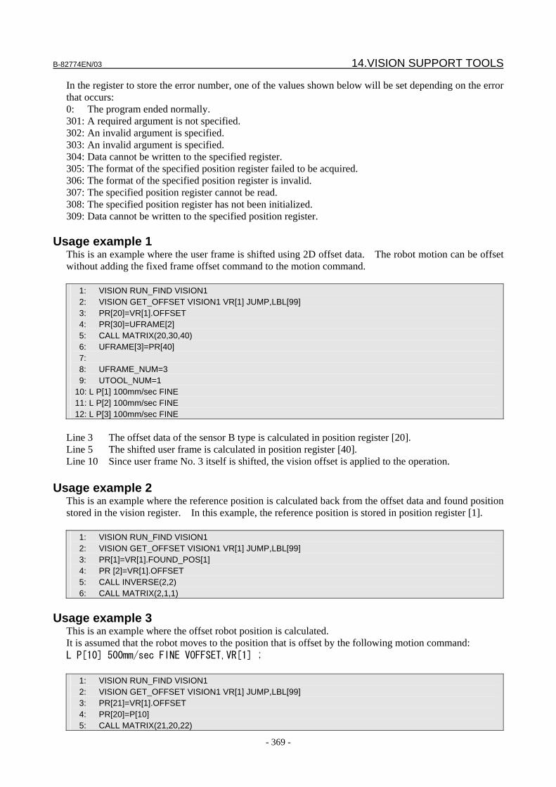
B-82774EN/03 14.VISION SUPPORT TOOLS
- 369 -
In the register to store the error number, one of the values shown below will be set depending on the error that occurs: 0: The program ended normally. 301: A required argument is not specified. 302: An invalid argument is specified. 303: An invalid argument is specified. 304: Data cannot be written to the specified register. 305: The format of the specified position register failed to be acquired. 306: The format of the specified position register is invalid. 307: The specified position register cannot be read. 308: The specified position register has not been initialized. 309: Data cannot be written to the specified position register.
Usage example 1 This is an example where the user frame is shifted using 2D offset data. The robot motion can be offset without adding the fixed frame offset command to the motion command. 1: VISION RUN_FIND VISION1 2: VISION GET_OFFSET VISION1 VR[1] JUMP,LBL[99] 3: PR[20]=VR[1].OFFSET 4: PR[30]=UFRAME[2] 5: CALL MATRIX(20,30,40) 6: UFRAME[3]=PR[40] 7: 8: UFRAME_NUM=3 9: UTOOL_NUM=1 10: L P[1] 100mm/sec FINE 11: L P[2] 100mm/sec FINE 12: L P[3] 100mm/sec FINE
Line 3 The offset data of the sensor B type is calculated in position register [20]. Line 5 The shifted user frame is calculated in position register [40]. Line 10 Since user frame No. 3 itself is shifted, the vision offset is applied to the operation.
Usage example 2 This is an example where the reference position is calculated back from the offset data and found position stored in the vision register. In this example, the reference position is stored in position register [1]. 1: VISION RUN_FIND VISION1 2: VISION GET_OFFSET VISION1 VR[1] JUMP,LBL[99] 3: PR[1]=VR[1].FOUND_POS[1] 4: PR [2]=VR[1].OFFSET 5: CALL INVERSE(2,2) 6: CALL MATRIX(2,1,1)
Usage example 3
This is an example where the offset robot position is calculated. It is assumed that the robot moves to the position that is offset by the following motion command: L P[10] 500mm/sec FINE VOFFSET,VR[1] ; 1: VISION RUN_FIND VISION1 2: VISION GET_OFFSET VISION1 VR[1] JUMP,LBL[99] 3: PR[21]=VR[1].OFFSET 4: PR[20]=P[10] 5: CALL MATRIX(21,20,22)
14.VISION SUPPORT TOOLS B-82774EN/03
- 370 -
Line 4 The position of P[10] and the offset data of the vision register are copied to the position
register. Line 5 Multiply the position with the offset data. The offset position is stored in position register
[22].
14.4 INVERSE This program regards the position register values given in the XYZWPR or matrix format as a homogeneous transform matrix and calculates the inverse matrix of the input matrix. When the input matrix is A and the output matrix is B, the program calculates the equation B=A-1. Argument 1:Position register number Specify the number of the position register storing input matrix A. Argument 2:Position register number Specify the number of the position register storing input matrix B. Argument 3:Register number Specify the number of the position register to store the error number. This argument can be omitted. In the register to store the error number, one of the values shown below will be set depending on the error that occurs: 0: The program ended normally. 201: A required argument is not specified. 202: An invalid argument is specified. 203: An invalid argument is specified. 204: The format of the specified position register failed to be acquired. 205: The format of the specified position register is invalid. 206: The specified position register cannot be read. 207: The specified position register has not been initialized. 208: Data cannot be written to the specified position register. 209: Data cannot be written to the specified register.
Usage example 1 This is an example where the matrix format of a position register is converted to the XYZWPR format. Executing INVERSE twice, as shown below, converts the matrix format of position register No. 1 to the XYZWPR format. 11: CALL INVERSE(1, 2) 12: CALL INVERSE(2, 1)
14.5 MERGE3D2 This program conducts 3D measurements at two or three positions on one workpiece and merges the results of those measurements to calculate the position and orientation of the entire workpiece. OFS_RJ3 generates 2D data, while MERGE3D2 generates 3D data. Argument 1:Position register number Specify the number of the position register storing 3D measurement results. Argument 2:Position register number Specify the number of the position register storing 3D measurement results.
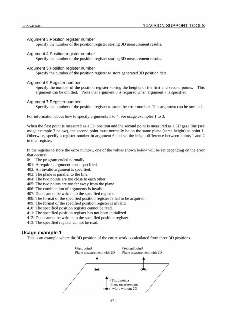
B-82774EN/03 14.VISION SUPPORT TOOLS
- 371 -
Argument 3:Position register number Specify the number of the position register storing 3D measurement results. Argument 4:Position register number Specify the number of the position register storing 3D measurement results. Argument 5:Position register number Specify the number of the position register to store generated 3D position data. Argument 6:Register number Specify the number of the position register storing the heights of the first and second points. This
argument can be omitted. Note that argument 6 is required when argument 7 is specified. Argument 7:Register number Specify the number of the position register to store the error number. This argument can be omitted. For information about how to specify arguments 1 to 4, see usage examples 1 to 3. When the first point is measured as a 3D position and the second point is measured as a 3D gaze line (see usage example 3 below), the second point must normally be on the same plane (same height) as point 1. Otherwise, specify a register number in argument 6 and set the height difference between points 1 and 2 in that register. In the register to store the error number, one of the values shown below will be set depending on the error that occurs: 0: The program ended normally. 401: A required argument is not specified. 402: An invalid argument is specified. 403: The plane is parallel to the line. 404: The two points are too close to each other. 405: The two points are too far away from the plane. 406: The combination of arguments is invalid. 407: Data cannot be written to the specified register. 408: The format of the specified position register failed to be acquired. 409: The format of the specified position register is invalid. 410: The specified position register cannot be read. 411: The specified position register has not been initialized. 412: Data cannot be written to the specified position register. 413: The specified register cannot be read.
Usage example 1 This is an example where the 3D position of the entire work is calculated from three 3D positions.
(First point) Plane measurement with 2D
(Third point) Plane measurement with / without 2D
(Second point)Plane measurement with 2D
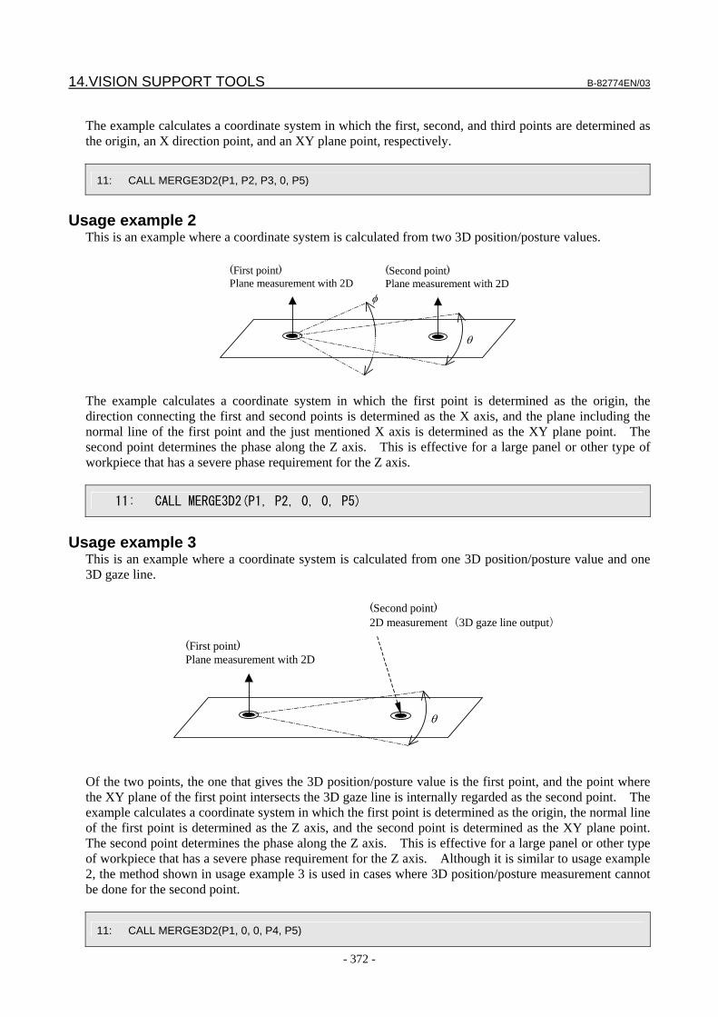
14.VISION SUPPORT TOOLS B-82774EN/03
- 372 -
The example calculates a coordinate system in which the first, second, and third points are determined as the origin, an X direction point, and an XY plane point, respectively.
11: CALL MERGE3D2(P1, P2, P3, 0, P5)
Usage example 2
This is an example where a coordinate system is calculated from two 3D position/posture values.
(First point) Plane measurement with 2D
θ
φ
(Second point)Plane measurement with 2D
The example calculates a coordinate system in which the first point is determined as the origin, the direction connecting the first and second points is determined as the X axis, and the plane including the normal line of the first point and the just mentioned X axis is determined as the XY plane point. The second point determines the phase along the Z axis. This is effective for a large panel or other type of workpiece that has a severe phase requirement for the Z axis.
11: CALL MERGE3D2(P1, P2, 0, 0, P5)
Usage example 3
This is an example where a coordinate system is calculated from one 3D position/posture value and one 3D gaze line.
(First point) Plane measurement with 2D
(Second point)2D measurement(3D gaze line output)
θ
Of the two points, the one that gives the 3D position/posture value is the first point, and the point where the XY plane of the first point intersects the 3D gaze line is internally regarded as the second point. The example calculates a coordinate system in which the first point is determined as the origin, the normal line of the first point is determined as the Z axis, and the second point is determined as the XY plane point. The second point determines the phase along the Z axis. This is effective for a large panel or other type of workpiece that has a severe phase requirement for the Z axis. Although it is similar to usage example 2, the method shown in usage example 3 is used in cases where 3D position/posture measurement cannot be done for the second point.
11: CALL MERGE3D2(P1, 0, 0, P4, P5)
B-82774EN/03 14.VISION SUPPORT TOOLS
- 373 -
CAUTION
In case of calculating a coordinate system from two position data, if one point is on the normal line of another point, calculation cannot be done, and an error occurs.
14.6 LOADNOM and SAVENOM If the free space of a position register is insufficient, the data in that position register can be saved. The total number of position registers that can be saved is 1470 - 30 position registers multiplied by 49 tables. Register data is saved and restored on a table-by-table basis.
SAVENOM This program saves position register data. Argument 1: Table number Specify the number of the table to which to save data. The specifiable value range is 1 to 49. Argument 2: Number of position registers Specify the number of position registers to save. The specifiable value range is 1 to 30. Argument 3:Position register number Specify the number of the first position register to save. Argument 4:Register number Specify the number of the position register to store the error number. This argument can be omitted. In the register to store the error number, one of the values shown below will be set depending on the error that occurs: 0: The program ended normally. 701: A required argument is not specified. 702: An invalid argument is specified. 703: An invalid argument is specified. 704: The format of the specified position register failed to be acquired. 705: The format of the specified position register is invalid. 706: The specified position register cannot be read. 707: The specified position register has not been initialized. 708: Data cannot be written to the specified register.
LOADNOM This program restores saved data to one or more position registers. Argument 1: Table number Specify the number of the table whose data is to be restored. The specifiable value range is 1 to 49. Argument 2: Number of position registers Specify the number of position registers to which to restore saved data. The specifiable value range
is 1 to 30. Argument 3:Position register number Specify the number of the first position register to which to restore saved data. Argument 4:Register number
14.VISION SUPPORT TOOLS B-82774EN/03
- 374 -
Specify the number of the position register to store the error number. This argument can be omitted. In the register to store the error number, one of the values shown below will be set depending on the error that occurs: 0: The program ended normally. 601: A required argument is not specified. 602: An invalid argument is specified. 603: An invalid argument is specified. 604: Data cannot be written to the specified position register. 605: Data cannot be written to the specified register. 606: The format of the specified position register failed to be acquired. 607: The format of the specified position register is invalid. 608: The specified table does not have any saved data.
Usage example 1 This is an example where the data of 10 position registers, [31] to [40], is saved to table 1 and then restored. 3: CALL SAVENOM(1,10,31) : 27: CALL LOADNOM(1,10,31)
Backup of the variable
The saved data is stored in the KAREL variable defined in the KAREL program SAVENOM. If you choose to save all files on the file screen, the saved data is saved in a file named SAVENOM.VR.
14.7 ADJ_OFS When a system performs 2D compensation, there may be cases where the system accomplishes fixed frame offsetting properly if the workpiece only moves horizontally without rotating, whereas an invalid fixed frame offset result is obtained if the workpiece rotates. The reason for this is that the coordinate system that the vision process recognizes through camera calibration does not match the user frame of the robot. To solve this problem: <1> After resetting the touch-up pin TCP for setting the coordinate system, reset the user frame, camera
calibration, and reference position, and re-teach the robot position. <2> If the fixed frame offset result is still invalid, perform vision mastering for the robot and then take
step <1>. This procedure may not be viable. In that case, using ADJ_OFS can improve the situation. Argument 1: Type of the register storing offset data Specify the type of register. Set 1 for a vision register and 2 for a position register. Argument 2: Vision register or position register number Specify the number of the vision register or position register storing offset data. Argument 3:Position register number Specify the number of the position register storing the amount of adjustment. Argument 4 : Vision register or position register number Specify the number of the vision register or position register to store adjusted offset data.
B-82774EN/03 14.VISION SUPPORT TOOLS
- 375 -
Argument 5:Register number Specify the number of the position register to store the error number. This argument can be omitted. You can specify the same number in arguments 2 and 4. If the register storing offset data is a position register, namely if 2 is set in argument 1, the format of the position register specified in argument 4 is automatically converted to the XYZWPR format. In the register to store the error number, one of the values shown below will be set depending on the error that occurs: 0: The program ended normally. 101: A required argument is not specified. 102: An invalid argument is specified. 103: The specified register type is invalid. 104: Data cannot be written to the specified register. 105: The specified vision register cannot be read. 106: Data cannot be written to the specified vision register. 107: The format of the specified position register failed to be acquired. 108: The format of the specified position register is invalid. 109: The specified position register cannot be read. 110: The specified position register has not been initialized. 111: Data cannot be written to the specified position register.
Usage example 1 This is an example where the offset data stored in vision register [1] is adjusted using the amount of adjustment stored in position register [11] and the adjusted offset data is output to vision register [2]. The adjusted offset data stored in vision register [2] is used to offset the robot position. If an error occurs, the program jumps to label [99]. 11: CALL ADJ_OFS(1, 1, 11, 2, 3) 12: IF R[3]<>0, JUMP,LBL[99] 13: L P[1] 100mm/sec FINE VOFFSET,VR[2]
Setting of the amount of adjustment
Set the amount of adjustment as follows: 1. Set XYZWPR=(0, 0, 0, 0, 0, 0) in the position register that stores the amount of adjustment. 2. Place the workpiece in the camera's field of view at the same angle as when the reference position
was set, and then run the program. 3. Touch up the workpiece using the robot. 4. If the position is invalid, subtract the offset value and re-teach the position. 5. Replace the workpiece by rotating it by 180 degrees, and then run the program. 6. Touch up the workpiece again using the robot. 7. If the touched up position is 10 mm off the expected position in the X direction, set half of 10 mm -
5 mm - in X of the position register that stores the amount of adjustment. 8. Set Y in the same way. Repeating steps 5 to 8 determines the amount of adjustment.
14.8 SORT_RJ3 This program sorts a position register storing found results of a vision process according to a specified sorting method. There are 13 specifiable sorting methods, as described later.
14.VISION SUPPORT TOOLS B-82774EN/03
- 376 -
Argument 1: Sorting method Specify the sorting method. The specifiable value range is 1 to 4, 11 to 18, and 21. Argument 2:Register number Specify the number of the register storing the number of found results to be sorted. Argument 3: Start number of the position register to sort Specify the start number of the position register storing the found results to be sorted. Argument 4: X-direction diameter or width of the workpiece Specify the X-direction diameter or width of the workpiece in mm. This argument is required
when the value set in argument 1 is 11 to 14. Otherwise, specify 0. Argument 5: Y-direction diameter or width of the workpiece Specify the Y-direction diameter or width of the workpiece in mm. This argument is required
when the value set in argument 1 is 15 to 18. Otherwise, specify 0. Argument 6:Position register number Specify the number of the position register storing the specified position when the value set in
argument 1 is 21. Sorting begins with the workpiece that is closest to this point. When the value set in argument 1 is not 21, specify 0.
Argument 7:Register number Specify the number of the register storing the flag that indicates whether to sort a register. If you
set 1 in the register specified here, when a position register is sorted, the register having the same number is sorted as well. Use this argument in such cases as when you want to sort the model IDs stored in a register in addition to position data. The argument can be omitted. Note that argument 7 is required when argument 8 is specified.
Argument 8:Register number Specify the number of the position register to store the error number. This argument can be omitted. In the register to store the error number, one of the values shown below will be set depending on the error that occurs: 0: The program ended normally. 1201: A required argument is not specified. 1202: An invalid argument is specified. 1203: The register storing the number cannot be read. 1204: The format of the register storing the number is invalid. 1205: The number is 0. 1206: The register storing the start number cannot be read. 1207: The format of the specified position register failed to be acquired. 1208: The format of the specified position register is invalid. 1209: The specified position register cannot be read. 1210: Data cannot be written to the specified position register. 1211: The format of an argument is invalid. 1212: The format of an argument is invalid. 1213: The value of the argument must be 0. 1214: The value set in the specified register must be 0. 1215: The value set in the argument must be greater than 0. 1216: The value set in the argument must be greater than 0. 1217: The value set in the argument must be greater than 0. 1218: There is an invalid argument.
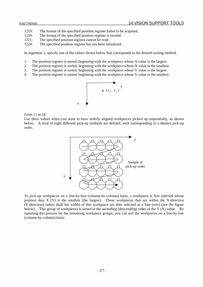
B-82774EN/03 14.VISION SUPPORT TOOLS
- 377 -
1219: The format of the specified position register failed to be acquired. 1220: The format of the specified position register is invalid. 1221: The specified position register cannot be read. 1224: The specified position register has not been initialized. In argument 1, specify one of the values shown below that corresponds to the desired sorting method. 1. The position register is sorted, beginning with the workpiece whose X value is the largest. 2. The position register is sorted, beginning with the workpiece whose X value is the smallest. 3. The position register is sorted, beginning with the workpiece whose Y value is the largest. 4. The position register is sorted, beginning with the workpiece whose Y value is the smallest.
y
x
),( 00 yx
From 11 to 18 Use these values when you want to have orderly aligned workpieces picked up sequentially, as shown below. A total of eight different pick-up methods are defined, each corresponding to a distinct pick-up order.
y
x
To pick up workpieces on a line-by-line (column-by-column) basis, a workpiece is first selected whose position data X (Y) is the smallest (the largest). Those workpieces that are within the X-direction (Y-direction) radius (half the width) of this workpiece are then selected as a line (row) (see the figure below). This group of workpieces is sorted in the ascending (descending) order of the Y (X) value. By repeating this process for the remaining workpiece groups, you can sort the workpieces on a line-by-line (column-by-column) basis.
Sample of pick-up order
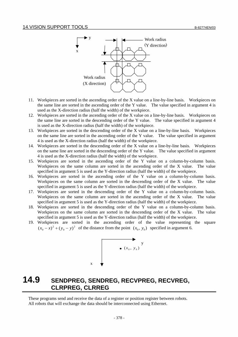
14.VISION SUPPORT TOOLS B-82774EN/03
- 378 -
y
x
Work radius(X direction)
Work radius(Y direction)
11. Workpieces are sorted in the ascending order of the X value on a line-by-line basis. Workpieces on
the same line are sorted in the ascending order of the Y value. The value specified in argument 4 is used as the X-direction radius (half the width) of the workpiece.
12. Workpieces are sorted in the ascending order of the X value on a line-by-line basis. Workpieces on the same line are sorted in the descending order of the Y value. The value specified in argument 4 is used as the X-direction radius (half the width) of the workpiece.
13. Workpieces are sorted in the descending order of the X value on a line-by-line basis. Workpieces on the same line are sorted in the ascending order of the Y value. The value specified in argument 4 is used as the X-direction radius (half the width) of the workpiece.
14. Workpieces are sorted in the descending order of the X value on a line-by-line basis. Workpieces on the same line are sorted in the descending order of the Y value. The value specified in argument 4 is used as the X-direction radius (half the width) of the workpiece.
15. Workpieces are sorted in the ascending order of the Y value on a column-by-column basis. Workpieces on the same column are sorted in the ascending order of the X value. The value specified in argument 5 is used as the Y-direction radius (half the width) of the workpiece.
16. Workpieces are sorted in the ascending order of the Y value on a column-by-column basis. Workpieces on the same column are sorted in the descending order of the X value. The value specified in argument 5 is used as the Y-direction radius (half the width) of the workpiece.
17. Workpieces are sorted in the descending order of the Y value on a column-by-column basis. Workpieces on the same column are sorted in the ascending order of the X value. The value specified in argument 5 is used as the Y-direction radius (half the width) of the workpiece.
18. Workpieces are sorted in the descending order of the Y value on a column-by-column basis. Workpieces on the same column are sorted in the descending order of the X value. The value specified in argument 5 is used as the Y-direction radius (half the width) of the workpiece.
19. Workpieces are sorted in the ascending order of the value representing the square 2
02
0 )()( yyxx −+− of the distance from the point ),( 00 yx specified in argument 6.
y
x
),( 00 yx
14.9 SENDPREG, SENDREG, RECVPREG, RECVREG, CLRPREG, CLRREG
These programs send and receive the data of a register or position register between robots. All robots that will exchange the data should be interconnected using Ethernet.
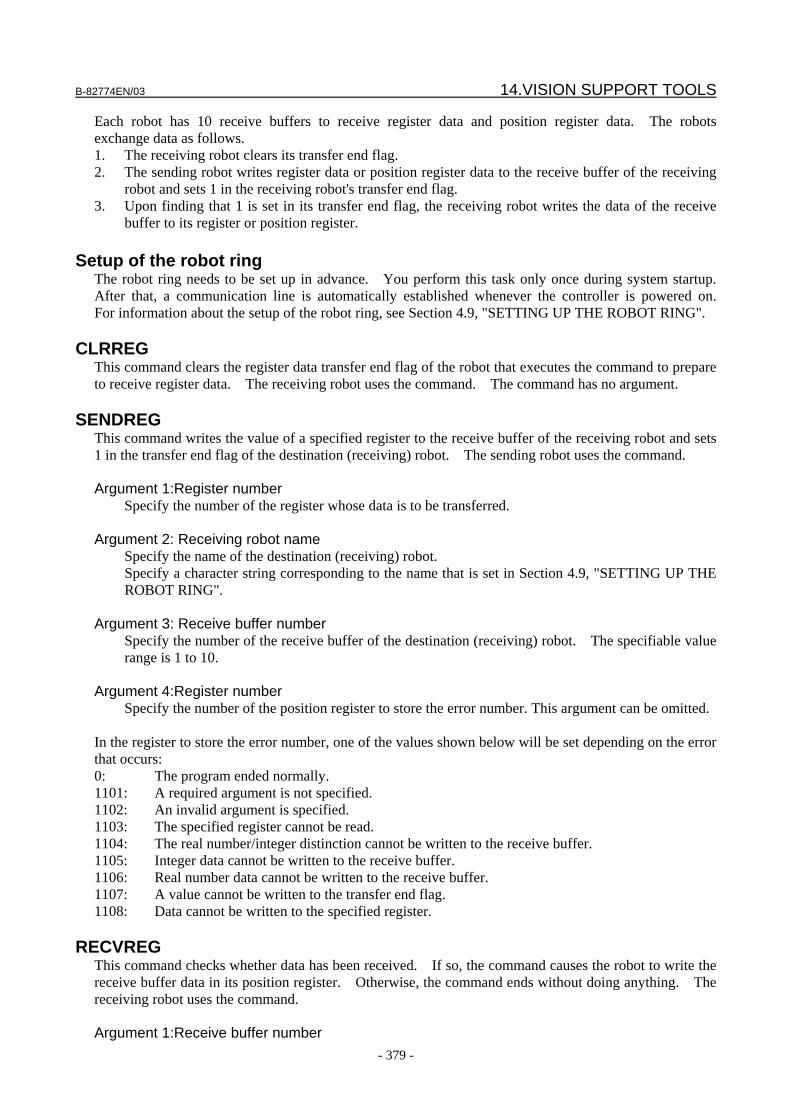
B-82774EN/03 14.VISION SUPPORT TOOLS
- 379 -
Each robot has 10 receive buffers to receive register data and position register data. The robots exchange data as follows. 1. The receiving robot clears its transfer end flag. 2. The sending robot writes register data or position register data to the receive buffer of the receiving
robot and sets 1 in the receiving robot's transfer end flag. 3. Upon finding that 1 is set in its transfer end flag, the receiving robot writes the data of the receive
buffer to its register or position register.
Setup of the robot ring The robot ring needs to be set up in advance. You perform this task only once during system startup. After that, a communication line is automatically established whenever the controller is powered on. For information about the setup of the robot ring, see Section 4.9, "SETTING UP THE ROBOT RING".
CLRREG This command clears the register data transfer end flag of the robot that executes the command to prepare to receive register data. The receiving robot uses the command. The command has no argument.
SENDREG This command writes the value of a specified register to the receive buffer of the receiving robot and sets 1 in the transfer end flag of the destination (receiving) robot. The sending robot uses the command. Argument 1:Register number Specify the number of the register whose data is to be transferred. Argument 2: Receiving robot name Specify the name of the destination (receiving) robot.
Specify a character string corresponding to the name that is set in Section 4.9, "SETTING UP THE ROBOT RING".
Argument 3: Receive buffer number Specify the number of the receive buffer of the destination (receiving) robot. The specifiable value
range is 1 to 10. Argument 4:Register number Specify the number of the position register to store the error number. This argument can be omitted. In the register to store the error number, one of the values shown below will be set depending on the error that occurs: 0: The program ended normally. 1101: A required argument is not specified. 1102: An invalid argument is specified. 1103: The specified register cannot be read. 1104: The real number/integer distinction cannot be written to the receive buffer. 1105: Integer data cannot be written to the receive buffer. 1106: Real number data cannot be written to the receive buffer. 1107: A value cannot be written to the transfer end flag. 1108: Data cannot be written to the specified register.
RECVREG This command checks whether data has been received. If so, the command causes the robot to write the receive buffer data in its position register. Otherwise, the command ends without doing anything. The receiving robot uses the command. Argument 1:Receive buffer number
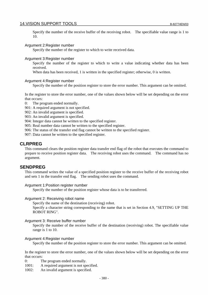
14.VISION SUPPORT TOOLS B-82774EN/03
- 380 -
Specify the number of the receive buffer of the receiving robot. The specifiable value range is 1 to 10.
Argument 2:Register number Specify the number of the register to which to write received data. Argument 3:Register number Specify the number of the register to which to write a value indicating whether data has been
received. When data has been received, 1 is written in the specified register; otherwise, 0 is written.
Argument 4:Register number Specify the number of the position register to store the error number. This argument can be omitted. In the register to store the error number, one of the values shown below will be set depending on the error that occurs: 0: The program ended normally. 901: A required argument is not specified. 902: An invalid argument is specified. 903: An invalid argument is specified. 904: Integer data cannot be written to the specified register. 905: Real number data cannot be written to the specified register. 906: The status of the transfer end flag cannot be written to the specified register. 907: Data cannot be written to the specified register.
CLRPREG This command clears the position register data transfer end flag of the robot that executes the command to prepare to receive position register data. The receiving robot uses the command. The command has no argument.
SENDPREG This command writes the value of a specified position register to the receive buffer of the receiving robot and sets 1 in the transfer end flag. The sending robot uses the command. Argument 1:Position register number Specify the number of the position register whose data is to be transferred. Argument 2: Receiving robot name Specify the name of the destination (receiving) robot.
Specify a character string corresponding to the name that is set in Section 4.9, "SETTING UP THE ROBOT RING".
Argument 3: Receive buffer number Specify the number of the receive buffer of the destination (receiving) robot. The specifiable value
range is 1 to 10. Argument 4:Register number Specify the number of the position register to store the error number. This argument can be omitted. In the register to store the error number, one of the values shown below will be set depending on the error that occurs: 0: The program ended normally. 1001: A required argument is not specified. 1002: An invalid argument is specified.
B-82774EN/03 14.VISION SUPPORT TOOLS
- 381 -
1003: The format of the specified position register failed to be acquired. 1004: The format of the specified position register is invalid. 1005: The specified position register cannot be read. 1006: The specified position register has not been initialized. 1007: The data of the position register cannot be written to the receive buffer. 1008: A value cannot be written to the transfer end flag. 1009: Data cannot be written to the specified register.
RECVPREG This command checks whether data has been received. If so, the command causes the robot to write the receive buffer data in its position register. Otherwise, the command ends without doing anything. The receiving robot uses the command. Argument 1:Receive buffer number Specify the number of the receive buffer of the receiving robot. The specifiable value range is 1 to
10. Argument 2:Position register number Specify the number of the position register to which to write received data. Argument 3:Register number Specify the number of the register to which to write a value indicating whether data has been
received. When data has been received, 1 is written in the specified register; otherwise, 0 is written.
Argument 4:Register number Specify the number of the position register to store the error number. This argument can be omitted. In the register to store the error number, one of the values shown below will be set depending on the error that occurs: 0: The program ended normally. 801: A required argument is not specified. 802: An invalid argument is specified. 803: An invalid argument is specified. 804: The format of the specified position register failed to be acquired. 805: The format of the specified position register is invalid. 806: The position data cannot be written to the specified position register. 807: The status of the transfer end flag cannot be written to the specified register. 808: Data cannot be written to the specified register.
Usage example 1 Program examples for the sending and receiving robots are given below, respectively. Receiving robot
14.VISION SUPPORT TOOLS B-82774EN/03
- 382 -
1: CALL CLRREG 2: CALL CLRPREG 3: R[2]=0 4: R[3]=0 5: 6: LBL[1] 7: CALL RECVREG(10,10,2,1) 8: IF R[2]=0 JUMP,LBL[1] 9: IF R[1]<>0 JUMP,LBL[99] 10: 11: LBL[2] 12: CALL RECVPREG(10,10,3,1) 13: IF R[3]=0 JUMP,LBL[2] 14: IF R[1]<>0 JUMP,LBL[99] 15: END : 25: LBL[99] 26: UALM[1]
Line 1 The register gets prepared to receive data. Line 2 The position register gets prepared to receive data. Line 7 A check is made to see whether the register data has been received. If so, the data of receive
buffer 10 is written in register [10]. Information about whether the data has been received is written in register [2].
Line 8 If the data has not been received yet, the program jumps to label [1] and makes the check again. Line 9 If an error occurs, the program jumps to label [99] to perform error processing. Line 12 A check is made to see whether the position register data has been received. If so, the data of
receive buffer 10 is written in position register 10. Information about whether the data has been received is written in register [3].
Line 13 If the data has not been received yet, the program jumps to label [2] and makes the check again. Line 14 If an error occurs, the program jumps to label [99] to perform error processing. Line 15 The program ends normally. Line 26 The program performs error processing. Sending robot 1: CALL SENDREG(1,'R2',10,1) 2: IF R[1]<>0 JUMP,LBL[99] 3: CALL SENDPREG(1,'R2',10,1) 4: IF R[1]<>0 JUMP,LBL[99] 5: END : 25: LBL[99] 26: UALM[1]
Line 1 The data of register [1] is sent to receive buffer 10 of robot R2. Line 2 If the data fails to be sent, the program jumps to label [99] to perform error processing. Line 3 The data of position register [1] is sent to receive buffer 10 of robot R2. Line 4 If the data fails to be sent, the program jumps to label [99] to perform error processing. Line 5 The program ended normally. Line 26 The program performs error processing.
14.10 CHK_POS Offsetting the robot position with iRVision may cause the robot to stop due to an alarm such as one that arises when the workpiece is outside the range of robot motion. This occurs, for example, if the

B-82774EN/03 14.VISION SUPPORT TOOLS
- 383 -
workpiece is within the detection range of iRVision but outside the range of robot motion or if the robot cannot take the specified posture to pick up the workpiece. CHK_POS checks whether the robot can move to the offset position before it actually travels there. The use of CHK_POS ensures that iRVision proceeds to process the next workpiece smoothly without causing any alarm. Argument 1: Group number Specify the motion group number of the robot. Argument 2: User frame number of the position data Specify the user frame number of the position data you want to check. Argument 3: Tool frame number of the position data Specify the tool frame number of the position data you want to check. Argument 4: Position register number Specify the number of the position register storing the position data you want to check. Argument 5: Position register number Specify the number of the position register storing the fixed frame offset data. Argument 6: Position register number Specify the number of the position register storing the tool offset data. Argument 7: Register number Specify the number of the register to store the error number. This argument cannot be omitted. In the register to store the error number, one of the values shown below will be set depending on the error that occurs: 0: The program ended normally.(The robot can move to the offset position.) 1301: A required argument is not specified. 1302: An invalid argument is specified. 1303: The specified user frame cannot be read. 1304: The specified tool frame cannot be read. 1305: Data cannot be written to the specified register. 1306: The system variable $MOR_GRP[x].$NIL_POS cannot be read. 1307: The format of the specified position register failed to be acquired. 1308: The format of the specified position register is invalid. 1309: The specified position register cannot be read. 1310: The specified position register has not been initialized. Other: Alarm number indicating the reason why the robot cannot move to the offset position (e.g., 15018 - MOTN-018 Position not reachable). Error codes from 1300 to 1399 indicate that an error has occurred during the execution of the tool. Other error codes are alarm codes that indicate the reason why the robot cannot move to the offset position. An alarm code consists of two high-order digits representing an alarm ID and three low-order digits representing an alarm number. In the case of 15018, for example, the alarm ID is 15, which indicates an operation alarm, and the alarm code is "MOTN-018". For details of the alarm codes, refer to the alarm code table provided in the "R-30iA Operations Manual".
14.VISION SUPPORT TOOLS B-82774EN/03
- 384 -
Usage example 1 11: J P[1] 100% FINE 12: PR[1]=P[2] 13: CALL CHK_POS(1,0,1,1,2,0,1) 14: IF R[1]<>0 JUMP,LBL [99] 15: L P[2] 2000mm/sec FINE OFFSET,PR [2] 16: LBL[99]
Line 12 The taught position (pre-offset position) is copied to the position register. Line 13 The group number is 1, the user frame number is 0, and the tool frame number is 1. Line 14 If the robot cannot move to the offset position, the program jumps to label [99]. Line 15 If the robot can move to the offset position, the program lets it do so.
14.11 STVS1 Based on the result of finding one workpiece with two cameras, this function calculates the 3D position of that workpiece in a stereo fashion. Using the bin-pick search vision process to detect the gaze lines from the camera to the workpiece, STVS1 determines the 3D position (XYZ) of the workpiece through stereo calculation utilizing the two cameras' gaze line data and saves the position in a position register. In the vision processes for both of these cameras, the same user frame needs to be set as [Application UFrame]. Argument 1:Position register number Specify the number of the position register storing the gaze line data of camera A. Argument 2:Position register number Specify the number of the position register storing the gaze line data of camera B. Argument 3:Register number Specify the number of the register storing the error limit of the distance between the two gaze lines
from the two cameras to the workpiece. The distance between gaze lines is the length of a common line that is perpendicular to the two gaze lines. When the two gaze lines completely cross each other, the distance between them is 0. If they do not cross each other due to error, the distance between them is a positive value. The 3D position is calculated only when the distance between gaze lines is below the error limit specified here.
Argument 4:Position register number Specify the number of the position register storing the calculated 3D position. Argument 5:Register number Specify the number of the position register to store the error number. This argument can not be
omitted. In the register to store the error number, one of the values shown below will be set depending on the error that occurs: 0: The program ended normally. 1401: A required argument is not specified. 1402: An invalid argument is specified. 1403: The data of the specified register failed to be obtained. 1404: Data cannot be written to the specified register. 1405: The format of the specified position register failed to be acquired. 1406: The format of the specified position register is invalid. 1407: The specified position register cannot be read. 1408: The specified position register has not been initialized.
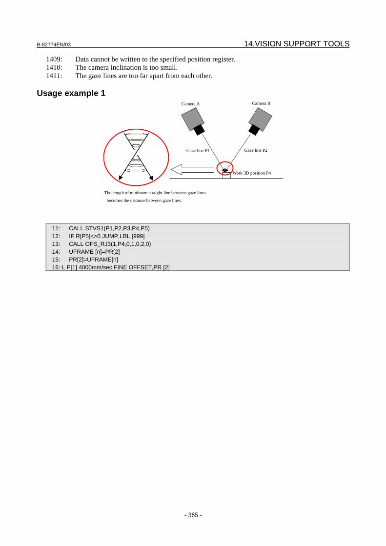
B-82774EN/03 14.VISION SUPPORT TOOLS
- 385 -
1409: Data cannot be written to the specified position register. 1410: The camera inclination is too small. 1411: The gaze lines are too far apart from each other.
Usage example 1 Camera A
Gaze line P1
Camera B
Gaze line P2
Work 3D position P4
The length of minimum straight line between gaze lines
becomes the distance between gaze lines.
11: CALL STVS1(P1,P2,P3,P4,P5) 12: IF R[P5]<>0 JUMP,LBL [999] 13: CALL OFS_RJ3(1,P4,0,1,0,2,0) 14: UFRAME [n]=PR[2] 15: PR[2]=UFRAME[n] 16: L P[1] 4000mm/sec FINE OFFSET,PR [2]
15.TROUBLESHOOTING B-82774EN/03
- 386 -
15 TROUBLESHOOTING When the iRVision does not operate as expected, check the information provided in this chapter.
15.1 ALARM CODES
CVIS-001: Not enough memory to process [Cause] The controller does not have a memory space sufficiently large enough to perform specified image processing. Turn off the power to the controller then turn on the power to the controller again. [Remedy] If this alarm is posted repeatedly, consider and take the following actions: • While the production line is under execution, do not open the iRVision setup window on PC. If a
setup window is opened, the setup window uses a significantly large memory space, so that memory space required for line execution may become unavailable.
• When a vision process based on multiple cameras or three-dimensional sensors is used, modify your TP program and add CAMERA_VIEW[X] to the VISION RUN_FIND command so that the VISION RUN_FIND command is called for each camera view. Compared with a case where all camera views are executed at a time, the maximum memory space momentarily required is reduced.
• Consider adjusting parameters for the pattern match tool that has been taught to the vision process. A larger memory space is needed as a larger search range is specified for the search window, angle, size, aspect, and so forth. A larger memory space is required as a smaller value is specified for the score threshold, contrast threshold, and so forth.
• Consider modifying a model pattern for the pattern match tool that has been taught to the vision process. As the figure of a model pattern is simpler, judgment as to whether the figure is identical is more difficult and a larger memory space is needed.
• Consider improving the illumination and background. If the background is more complicated and its image varies more in darkness, a larger memory space is required for detection.
When the situation is not improved even if the actions above are taken, Contact FANUC or FANUC Robotics, or FANUC Robotics.
CVIS-002: Bad arguments to the function [Cause] Internal error. [Remedy] Contact FANUC or FANUC Robotics.
CVIS-003: Cannot find specified file [Cause] The specified file does not exist on the disk. [Remedy] Enter the correct file name.
CVIS-004: The file already exists [Cause] The specified file already exists. [Remedy] Specify another file name.
B-82774EN/03 15.TROUBLESHOOTING
- 387 -
CVIS-005: File access is denied [Cause] The specified file is for read only. [Remedy] Change the file attribute.
CVIS-006: Not enough space on the disk [Cause] There is not enough space on the disk of the controller to write the file. [Remedy] Delete unnecessary files. When there are no unnecessary files and this message persists, Contact FANUC or FANUC Robotics.
CVIS-007: Invalid/unsupported BMP file [Cause] The BMP file is corrupted or uses an unsupported file format. [Remedy] The iRVision supports 8 bit/pixel BMP and PNG only.
CVIS-008: Bad vector/matrix dimensions [Cause] Internal error. [Remedy] Contact FANUC or FANUC Robotics.
CVIS-009: The matrix is not square [Cause] Internal error. [Remedy] Contact FANUC or FANUC Robotics.
CVIS-010: The matrix is singular [Cause] Internal error. [Remedy] Contact FANUC or FANUC Robotics.
CVIS-011: The objects are parallel [Cause] Internal error. [Remedy] Contact FANUC or FANUC Robotics.
CVIS-012: The quadratic is a parabola [Cause] Internal error. [Remedy] Contact FANUC or FANUC Robotics.
CVIS-013: The quadratic is a hyperbola [Cause] Internal error. [Remedy]
15.TROUBLESHOOTING B-82774EN/03
- 388 -
Contact FANUC or FANUC Robotics.
CVIS-014: Not enough points for fitting [Cause] Internal error. [Remedy] Contact FANUC or FANUC Robotics.
CVIS-015: Too few calibration points [Cause] Calibration points are too few to accomplish calibration. [Remedy] The minimum number of the points is five for one surface or seven for two surfaces. However, a large dot must be found. Check whether all calibration points are found properly.
CVIS-016: Cannot calibrate the camera [Cause] Calibration cannot be accomplished with the found points. [Remedy] Check whether all calibration points are found properly.
CVIS-017: Invalid file name [Cause] The specified file name is invalid. [Remedy] No file name is entered or an attempt is made to save an image in a format other than BMP or PNG. Enter a file name with the extension BMP or PNG.
CVIS-018: The mask size is bad [Cause] Internal error. [Remedy] Contact FANUC or FANUC Robotics.
CVIS-019: The window size is bad [Cause] Set window size is invalid. [Remedy] Change the size of the window.
CVIS-020: Big circles cannot be distinguished [Cause] In calibration grid plate measurement, four large circles could not be recognized correctly. [Remedy] Check whether the calibration plate is inclined too much. Take the following actions so that the large circles can be detected correctly. • Clean the plate if dirty. • Replace the plate with a new one if the plate has a large flaw. • Adjust the search range so that the range contains the plate. • If the background appears around the plate, hide the background with a sheet.
CVIS-021: Exceed VisPool (xx Bytes) [Cause]
B-82774EN/03 15.TROUBLESHOOTING
- 389 -
Vision pool lacked sufficient available memory to perform the specified image processing, so the image processing was performed using some memory from Temporary pool. The alarm message shows the amount of memory used from Temporary pool. [Remedy] Urgent remedy would not be needed, but if this alarm is posted too frequently, consider taking the following actions: • While the production line is under execution, do not open the iRVision setup window on PC. If a
setup window is opened, the setup window uses a significantly large memory space, so that memory space required for line execution may become unavailable.
• When a vision process based on multiple cameras or three-dimensional sensors is used, modify your TP program and add CAMERA_VIEW[X] to the VISION RUN_FIND command so that the VISION RUN_FIND command is called for each camera view. Compared with a case where all camera views are executed at a time, the maximum memory space momentarily required is reduced.
• Consider adjusting parameters for the pattern match tool that has been taught to the vision process. A larger memory space is needed as a larger search range is specified for the search window, angle, size, aspect, and so forth. A larger memory space is required as a smaller value is specified for the score threshold, contrast threshold, and so forth.
• Consider modifying a model pattern for the pattern match tool that has been taught to the vision process. As the figure of a model pattern is simpler, judgment as to whether the figure is identical is more difficult and a larger memory space is needed.
• Consider improving the illumination and background. If the background is more complicated and its image varies more in darkness, a larger memory space is required for detection.
When frequency of this alarm does not decrease even if the actions above are taken, you can enlarge the vision pool size. The vision pool size is defined with $VISPOOL_SIZ system variable (its default value is 4000000 = 4 M bytes). To change the vision pool size, change the system variable, and reboot the controller.
NOTE By enlarging the vision pool, size of Temporary pool decreased. Make sure that
available memories in Temporary pool at controller start up is larger than 3M bytes.
When the situation is not improved even if the actions above are taken, Contact FANUC or FANUC Robotics.
CVIS-030: The model pattern is not trained. [Cause] GPM Locator Tool was executed without the model pattern trained. [Remedy] Teach the model of a pattern match.
CVIS-031: There are not enough features in the training window [Cause] GPM Locator Tool error. When a model was taught, no feature was found in its image or features were found but they were insufficient. [Remedy] Use another part of the image as the model or teach a model using another image by taking it after adjusting the exposure time so that the contrast becomes high.
CVIS-032: Bad arguments [Cause] Internal error.
15.TROUBLESHOOTING B-82774EN/03
- 390 -
[Remedy] Contact FANUC or FANUC Robotics.
CVIS-033: The operation has timed out [Cause] GPM Locator Tool error. The location processing time in a pattern match has exceeded the specified [Timeout] setting. [Remedy] Increase the allowable processing time. Alternatively, make one of the following adjustments so as to decrease the required processing time. • Use a complex geometry as the model. • Uncheck the orientation, scale, and aspect ratio check boxes whichever are unnecessary. • Specify a larger score threshold. • Specify a larger contrast threshold. • Narrow the orientation, scale, and aspect ratio search ranges. • Reduce the size of the search window.
CVIS-034: The emphasis area is not trained [Cause] GPM Locator Tool error. No emphasis area is set when the use of the emphasis area is enabled in the GPM Locator Tool Setup window. [Remedy] Take one of the following actions: • When not using the emphasis area, uncheck the [Enable] box for Emphasis Area. • When using the emphasis area, click the [Edit EA].
CVIS-035: The emphasis area is too large [Cause] GPM Locator Tool error. The set emphasis area is too large. [Remedy] Set a smaller emphasis area.
CVIS-036: The emphasis area is too small [Cause] GPM Locator Tool error. The set emphasis area is too small. [Remedy] Set a larger emphasis area.
CVIS-037: The model pattern is not symmetrical [Cause] GPM Locator Tool error. For a non-rotatable model, an attempt was made to have the model origin automatically set by clicking the "Center Origin" button. [Remedy] The model origin of a non-rotatable model cannot be set automatically by clicking the "Center Origin" button. Use the "Set Origin" button to set the model origin.
CVIS-038: Too many candidates to process [Cause] GPM Locator Tool error. The image has too many candidate patterns to evaluate, so the requested image process could not be done. [Remedy] Make the following adjustments to reduce the search candidates: • Use a complex geometry as the model pattern.
B-82774EN/03 15.TROUBLESHOOTING
- 391 -
• Uncheck the unnecessary items of Orientation, Scale, and Aspect Ratio. • Specify a larger score threshold. • Specify a larger contrast threshold. • Narrow the search ranges for Orientation, Scale, and Aspect Ratio. • Reduce the size of the search window. • Improve lighting to reduce noise in the images.
CVIS-039: The mask doesn't fit the model pattern [Cause] Internal error. [Remedy] Contact FANUC or FANUC Robotics.
CVIS-040: The mask doesn't fit the search window [Cause] Internal error. [Remedy] Contact FANUC or FANUC Robotics.
CVIS-041: File version error [Cause] GPM Locator Tool error. The version of the GPM Locator Tool data saved in the file is too new. [Remedy] Update the controller software to the newest version or re-create the data.
CVIS-042: File is broken [Cause] GPM Locator Tool error. The GPM locator tool data stored in the file is corrupted. [Remedy] Contact FANUC or FANUC Robotics.
CVIS-043: The search window is too small [Cause] GPM Locator Tool error. The set search window is too small. [Remedy] Expand the size of the search window.
CVIS-050: Exposure is invalid [Cause] The exposure time is too long or short. [Remedy] Set it in the range from 0.04 ms to 250 ms.
CVIS-051: Laser window is invalid [Cause] No laser measurement area has been set up or a set laser measurement area is too small. [Remedy] Re-teach a measurement area. The minimum allowable laser measurement area is 8 pixels in both height and width. If it is necessary to measure laser beams in a smaller area, increase the size of the measurement area and then limit it by setting up a mask.
CVIS-052: Calibration data is not perspective [Cause]
15.TROUBLESHOOTING B-82774EN/03
- 392 -
The calibration data is improper. [Remedy] Make sure that 3D laser sensor calibration data has been selected.
CVIS-053: Calculation is not converged [Cause] Measured laser spots did not converge at one point. The probable causes are: the calibration data is incorrect; within the measurement range, the height of a workpiece differs largely from that of another workpiece. [Remedy]
CVIS-054: Laser line is not found [Cause] No straight line was found from a string of laser spots. [Remedy] First, adjust the setting of exposure so that an appropriate laser image can be obtained. Next, make sure that the laser measurement area was taught properly. If the pattern match model origin is changed after the laser measurement area has been taught, it is likely that the laser measurement area may move to an unintended position during execution. If you changed the model origin, re-set the laser measurement area. If these methods cannot solve the problem, adjust the detection parameter for the string of laser spots.
CVIS-055: Not enough laser points for calculation [Cause] The number of detected laser points is less than the threshold. [Remedy] First, adjust the setting of exposure so that an appropriate laser image can be obtained. Next, make sure that the laser measurement area was taught properly. If the pattern match model origin is changed after the laser measurement area has been taught, it is likely that the laser measurement area may move to an unintended position during execution. If you changed the model origin, re-set the laser measurement area. If these methods cannot solve the problem, adjust the detection parameter for the string of laser spots. Alternatively, enabling the [Search narrow area] function can increase the number of laser spots even if the measurement area remains the same.
CVIS-056: Laser plane is not found [Cause] No plane was found during laser measurement. [Remedy] First, adjust the setting of exposure so that an appropriate laser image can be obtained. Next, make sure that the laser measurement area was taught properly. If the pattern match model origin is changed after the laser measurement area has been taught, it is likely that the laser measurement area may move to an unintended position during execution. If you changed the model origin, re-set the laser measurement area. If these methods cannot solve the problem, adjust the detection parameter for the string of laser spots.
CVIS-057: Zero vector is used in calculation [Cause] This is an internal error found during laser measurement. [Remedy] Contact FANUC or FANUC Robotics.
CVIS-058: Input data is out of range [Cause] This is an internal error found during laser measurement.
B-82774EN/03 15.TROUBLESHOOTING
- 393 -
[Remedy] Contact FANUC or FANUC Robotics.
CVIS-059: Leaning angle exceeded limit [Cause] During 3D measurement, it was found that the workpiece had been tilted more than the setting, as compared with when the reference data was obtained. [Remedy] If this tilting of the workpiece is permissible, increase the setting. Otherwise, eject the workpiece. Alternatively, make adjustments so that the tilting of the workspace will fall within the setting.
CVIS-061: Parameter is not initialized [Cause] Vision Shift error. This is an internal error. [Remedy] Contact FANUC or FANUC Robotics.
CVIS-062: Target is rotated too much [Cause] Vision Shift error. Unable to find a target in an image because the rotation angle of the target is larger than the allowable rotation angle. [Remedy] Adjust the 'Rotation Angle' parameter in vision setup screen.
CVIS-063: Target is too close [Cause] Vision Shift error. Unable to find a target in an image because the target in an image is too large. The distance between a camera and a target may be shorter than allowable distance limit. [Remedy] Check the distance between the target and the camera, or adjust the 'Distance Limit' parameter in vision setup screen.
CVIS-064: Target is too far away [Cause] Vision Shift error. Unable to find a target in an image because the target in an image is too small. The distance between a camera and a target may be longer than allowable distance limit. [Remedy] Check the distance between the target and the camera, or adjust the 'Distance Limit' parameter in vision setup screen.
CVIS-065: Target is tilted too much [Cause] Vision Shift error. Unable to find a target in a image because the target in a image is too small. The distance between a camera and a target may be longer than allowable distance limit. [Remedy] Check the distance between the target and the camera, or adjust the 'Distance Limit' parameter in vision setup screen.
CVIS-066: Contrast is too low [Cause] Vision Shift error. Unable to find a target in a image because the image contrast is low. The image contrast may be lower than the image contrast threshold. [Remedy]
15.TROUBLESHOOTING B-82774EN/03
- 394 -
Check the image and adjust camera and lighting conditions so that the clear target image can be captured. Otherwise adjust the "Contrast" parameter in vision setup screen.
CVIS-067: Target is not clear [Cause] Vision Shift error. Unable to find a target in a image because the detection score is low. The score of geometrical feature matching between the target and the taught model may be less than the threshold value. [Remedy] Check the image or adjust the "Score" parameter in vision setup screen.
CVIS-068: Mastering calculation is failed [Cause] Vision Shift error. This is an internal error. [Remedy] Contact FANUC or FANUC Robotics.
CVIS-069: Data is not for vision shift [Cause] Vision Shift error. Specified vision data is not for vision shift. The specified vision data may be created by iRVision setup. [Remedy] Rename or delete the currently specified vision data using iRVision setup, then create the vision data using vision setup screen for Vision Shift.
CVIS-070: Remove Vision Board [Cause] Vision Shift cannot run when the vision board is plugged in. [Remedy] Remove the vision board temporarily while running Vision Shift.
CVIS-080: The camera is busy [Cause] The camera is busy in processing an image and cannot respond to the request. [Remedy] Wait until the processing ends.
CVIS-081: Invalid camera type specified [Cause] The specified camera type is invalid. [Remedy] Specify a camera of a valid type.
CVIS-082: Invalid image object passed [Cause] Internal error. [Remedy] Contact FANUC or FANUC Robotics.
CVIS-083: Exposure time is out of range [Cause] The specified exposure time is out of range. [Remedy] Specify an exposure time within the range (0.04 to 250 ms).
B-82774EN/03 15.TROUBLESHOOTING
- 395 -
CVIS-084: Invalid camera port specified
[Cause] An invalid camera port number is specified. [Remedy] Specify a valid camera port number.
CVIS-085: Camera time out [Cause] Internal error. [Remedy] Contact FANUC or FANUC Robotics.
CVIS-086: Camera is not 3D laser sensor [Cause] The specified camera port number cannot be used by a 3D sensor. [Remedy] Set a proper port number.
CVIS-087: DEPICT error [Cause] Images could not be captured by a USB camera. [Remedy] Contact FANUC or FANUC Robotics.
CVIS-088: Vision FPGA version error [Cause] The FPGA version is too old. [Remedy] Contact FANUC or FANUC Robotics.
CVIS-089: Camera is not initialized [Cause] The camera is not initialized. The hardware may be damaged. [Remedy] Contact FANUC or FANUC Robotics.
CVIS-090: Vision DMA error [Cause] A DMA error occurred during the image capture. The hardware may be damaged. [Remedy] Contact FANUC or FANUC Robotics.
CVIS-091 The auto exposure setting is not trained [Cause] Although the vision process is configured to use the auto exposure function, it is executed with the auto exposure function not taught. [Remedy] Teach the auto exposure function.
CVIS-092: The auto exposure setting is too bright [Cause] The area taught by the auto exposure function is too bright. [Remedy]
15.TROUBLESHOOTING B-82774EN/03
- 396 -
Teach a different area or turn down the lighting.
CVIS-093: The auto exposure setting is too dark [Cause] The area taught by the auto exposure function is too dark. [Remedy] Teach a different area, or turn up the lighting.
CVIS-094: The auto exposure setting is bad [Cause] The auto exposure function setting is invalid. [Remedy] Teach it again.
CVIS-095: This Board has no CAMERA I/F [Cause] Camera I/F circuit is not implemented on your hardware. So vision functions cannot be used.
CVIS-096: Multi exposure exceeded the limit. Number of exposures will be modified at execution
[Cause] Exposure times calculated for the multi-exposure function exceed the limit of the exposure time available with the camera. So number of exposures will be different from your setting. [Remedy] Usually not needed. But changing the number of exposures or exposure time may be recommended.
CVIS-097: Area is not trained. Area is reset. [Cause] Area of the set window is zero. So now the multi-exposure window has been set to the default window. [Remedy] Not needed.
CVIS-098: The camera is disconnected [Cause] The power to the camera is turned off with the sensor disconnect function. [Remedy] After connecting the camera, execute the sensor connect command to feed power to the camera.
CVIS-099: Not support this config of MUX [Cause] The sensor disconnect function cannot be used with the multiplexer currently used. [Remedy] Check the type of multiplexer.
CVIS-100: A vision data file with that name already exists. [Cause] A vision data file with the specified name already exists. [Remedy] Specify another file name.
CVIS-101: The vision data file does not exist. [Cause] A vision data file with the specified name does not exist. [Remedy]
B-82774EN/03 15.TROUBLESHOOTING
- 397 -
Specify an existent vision data file.
CVIS-102: Invalid vision data pointer [Cause] Internal error. [Remedy] Contact FANUC or FANUC Robotics.
CVIS-103: The vision data file is already open for writing [Cause] The specified vision data is currently in use. [Remedy] Close the vision data before performing the operation.
CVIS-104: No more vision data found [Cause] Internal error. [Remedy] Contact FANUC or FANUC Robotics.
CVIS-105: Cannot delete the vision data file because it is open [Cause] The specified vision data cannot be deleted because it is currently in use or because another vision data file using it is currently in use. [Remedy] Close the vision data before deleting it.
CVIS-106: Cannot rename the vision data file because it is open [Cause] The specified vision data cannot be renamed because it is currently in use. [Remedy] Close the vision data before renaming it.
CVIS-107: Cannot apply because reserved [Cause] The specified vision data cannot be saved because it is currently in use. [Remedy] Close the vision data before saving it.
CVIS-108: Tool type not found [Cause] This vision data contains a vision tool not supported by the controller. [Remedy] Please purchase an option that can be used by this vision data.
CVIS-109: Interface not supported [Cause] Internal error. [Remedy] Contact FANUC or FANUC Robotics.
CVIS-110: Double registration [Cause] Internal error.
15.TROUBLESHOOTING B-82774EN/03
- 398 -
[Remedy] Contact FANUC or FANUC Robotics.
CVIS-111: The vision data file is broken [Cause] The vision data file is corrupted. [Remedy] Contact FANUC or FANUC Robotics.
CVIS-112: Parent camera view not found [Cause] Internal error. [Remedy] Contact FANUC or FANUC Robotics.
CVIS-113: The vision data file is too old to load [Cause] The vision data cannot be opened because it was created with an incompatible version of UIF. [Remedy] Create a new vision data file. Alternatively, use the UIF version that was used in creating the vision data.
CVIS-114: The vision data file is too new to load [Cause] The vision data cannot be opened because it was created with a UIF version newer than the currently installed UIF version. [Remedy] Create a new vision data file. Alternatively, upgrade the UIF to the version used to create the vision data.
CVIS-115: Invalid vision data name [Cause] The vision data name contains one or more invalid characters. [Remedy] Check the vision data name.
CVIS-116: There is not enough space on the disk [Cause] Disk free space is not sufficiently large for saving the vision data. [Remedy] Delete unnecessary vision data. For radical measures, see Subsection 11.2.3, "To Create More Vision Data".
CVIS-117: Cannot insert this tool [Cause] The selected tool cannot be inserted. [Remedy] The 3DL vision process allows only laser measurement tools of the same type to be added. If it is necessary to add a different type, the existing laser measurement tools must be deleted.
CVIS-118: Target Controller has no vision [Cause] The target controller has no vision option. [Remedy]
B-82774EN/03 15.TROUBLESHOOTING
- 399 -
Select a controller that has a vision option.
CVIS-119: The vision program can not output this vision parameter [Cause] This parameter cannot be output. [Remedy] Select the correct parameter.
CVIS-120: Could not log data [Cause] A vision log could not be recorded. [Remedy] Create free space by inserting a new memory card into the controller, using a memory card with a larger capacity, or deleting unnecessary files from the memory card.
CVIS-121: Could not log image [Cause] A vision log image could not be recorded. [Remedy] Create free space by inserting a new memory card into the controller, using a memory card with a larger capacity, or deleting unnecessary files from the memory card.
CVIS-122: Log file is broken [Cause] This version of controller cannot read the specified vision log. [Remedy] Use a controller of the newer version.
CVIS-123: Unknown tag specified to log [Cause] Internal error of the vision log function. [Remedy] Contact FANUC or FANUC Robotics.
CVIS-124: Bad log file open mode [Cause] Internal error of the vision log function. [Remedy] Contact FANUC or FANUC Robotics.
CVIS-125: Log record is full [Cause] Internal error of the vision log function. [Remedy] Contact FANUC or FANUC Robotics.
CVIS-126: No more elements in log record [Cause] Internal error of the vision log function. [Remedy] Contact FANUC or FANUC Robotics.
CVIS-127: Invalid index specified [Cause]
15.TROUBLESHOOTING B-82774EN/03
- 400 -
Internal error of the vision log function. [Remedy] Contact FANUC or FANUC Robotics.
CVIS-128: Specified tag not found [Cause] Internal error of the vision log function. [Remedy] Contact FANUC or FANUC Robotics.
CVIS-129: Unknown tag found in log file [Cause] The vision log file is too new and cannot be read with this controller.
CVIS-130: No free disk space to log [Cause] The vision log could not be recorded. [Remedy] Create free space by inserting a new memory card into the controller, using a memory card with a larger capacity, or deleting unnecessary files from the memory card.
CVIS-131: Resume data logging [Cause] The recording of the vision log has been resumed. [Remedy] Not needed.
CVIS-132: Cannot log because of bad clock setup [Cause] The clock setup of the controller is incorrect, so that vision log could not be recorded. [Remedy] Set the clock of the controller to correct time.
CVIS-133: Missing my work area [Cause] The work area of the controller cannot be found. [Remedy] Teach line data.
CVIS-134: Line data is not trained [Cause] Line data is not trained. [Remedy] Teach line data.
CVIS-136: Please enter a valid robot IP address [Cause] The set IP address is incorrect. [Remedy] Enter the correct IP address.
CVIS-137: The robot name XXX or IP address is already in use [Cause]
B-82774EN/03 15.TROUBLESHOOTING
- 401 -
The same robot name or IP address is already used. [Remedy] Change the robot name or IP address.
CVIS-138: The robot name must start with a letter, contain no spaces, not contain the characters ¥/:*?"<>|
[Cause] When entering a robot name, use half-size letters or katakana characters. Do not use a number as the first character. Moreover, do not use a space, ¥, /, :, *, ?, ", <, >, and |. [Remedy] Enter a valid robot name.
CVIS-139: Cannot delete this tool
[Cause] The specified tool cannot be deleted from the tree window. Some programs have been designed to prevent the number of command tools from being set below a predetermined number. [Remedy] Before trying to delete the specified tool, create another one.
CVIS-140: The value %s is out of range. The valid range is %s to %s. [Cause] The specified value is out of range. [Remedy] Specify a value within the range.
CVIS-141: The tool name '%s' is already in use [Cause] The specified name is already in use. [Remedy] Specify another name.
CVIS-142: The tool name must start with a letter, contain no spaces, not contain the characters ¥/:*?""<>|, and be 34 characters or less.
[Cause] The specified name is invalid. [Remedy] Specify a valid name.
CVIS-143: The image display is busy setting a cursor, a window, or a mask. [Cause] An attempt was made to perform another operation while a window or mask was being set. [Remedy] Complete the setting of the window or mask before performing another operation.
CVIS-144: The name has been truncated to XXX [Cause] A specified name was too long, so that the name was cut to an appropriate length. [Remedy] If the cut name is unacceptable, specify a shorter name.
CVIS-145: The image display is in live mode.
[Cause] An attempt was made to perform another operation while an image was being displayed in live mode.
15.TROUBLESHOOTING B-82774EN/03
- 402 -
[Remedy] Complete the live mode display before performing another operation.
CVIS-146: There is no image. [Cause] An attempt was made to teach a model using a pattern match when there was no image snapped. [Remedy] Snap an image or read a saved image file.
CVIS-147: Load failed for %s. [Cause] The tool failed to be loaded.
CVIS-148: There are no found results. [Cause] No object was found. [Remedy] Adjust the exposure so that an appropriate image can be taken. Alternatively, adjust the parameter.
CVIS-149: The system is busy doing continuous snaps and finds. [Cause] Continuous location is under way. [Remedy] Before trying to perform another operation, press the [Stop S+F] button to stop the continuous location.
CVIS-150: Camera view index out of range [Cause] The camera view number specified in a location command is out of range. [Remedy] Specify a valid camera view number.
CVIS-151: No more vision offsets [Cause] An attempt was made to acquire offset data before location is performed. Another cause is that offset data was not calculated because the combine error exceeded the threshold in a multi-view vision process. [Remedy] Perform location first. Alternatively, for a multi-view vision process, check whether the combine error is equal to or less than the threshold.
CVIS-152: Failed to set ref. position [Cause] The program found no object. [Remedy] Before continuing the operation, have an object found using a location command.
CVIS-153: Ref. position has not been set [Cause] The reference position is not set. [Remedy] Set the reference position by executing the SET_REFERENCE instruction or clicking the [Set Ref. Pos] button in the setup window.
CVIS-154: Reference data does not exist [Cause]
B-82774EN/03 15.TROUBLESHOOTING
- 403 -
No reference data exists for the found model ID. [Remedy] Create reference data in which the found model ID is set using the Setup window, and set the reference position.
CVIS-155: Bad vision process name [Cause] The specified program name contains one or more invalid characters. [Remedy] Check the program name.
CVIS-156: Vision process was not found [Cause] The specified program name does not exist. [Remedy] Check whether the specified program exists and specify the correct program name.
CVIS-157: Camera does not exist [Cause] The specified camera does not exist. [Remedy] Check whether the specified camera exists and specify the correct camera name.
CVIS-158: Camera calib. does not exist [Cause] The specified calibration data does not exist. [Remedy] Check whether the calibration data exists and specify the correct calibration data name.
CVIS-159: Inappropriate request to tool [Cause] The specified vision data cannot respond to the requested command. [Remedy] Verify if the correct vision data name is specified in the TP program.
CVIS-160: Find has not been executed [Cause] No location has been performed before setting the reference point. [Remedy] Before continuing the operation, perform location by executing the RUN_FIND command or pressing the Find button in the Setup Page.
CVIS-161: No camera setup is selected [Cause] No camera is selected in the Calibration Setup window. [Remedy] Select a camera.
CVIS-162: No camera calibration selected [Cause] No camera calibration data has been selected for the vision program. [Remedy] Select calibration data.

15.TROUBLESHOOTING B-82774EN/03
- 404 -
CVIS-163: No reference robot position for tool offset [Cause] While the robot position used when the reference position is set is necessary for tool offset, it is not set properly in this vision program. [Remedy] Set the reference position again.
CVIS-164: No robot position for robot mounted camera [Cause] The robot-mounted camera requires the robot position to calculate the position of the workpiece. The test cannot be done with the image read from a file. [Remedy] Snap an image using the Snap button.
CVIS-165: No robot position for tool offset [Cause] Tool offset requires the robot position to calculate the position of the workpiece. The test cannot be done with the image read from a file. [Remedy] Snap an image using the Snap button.
CVIS-166: Vision Standard DEMO expired [Cause] The 60-day use period of the iRVision demo version has expired. For more information, choose Control from Start for the controller and then choose "MENUS" → "INSTALL" → "Option" → "Demo". [Remedy] If you want to continue to use iRVision, order a vision option.
CVIS-167: Target Controller is too old to communicate [Cause] The target controller is too old to communicate. [Remedy] Upgrade the software of the controller.
CVIS-168: Target Controller is off-line [Cause] The target controller is off-line. [Remedy] Check whether the target controller is powered on and connected to the network.
CVIS-169: Object is not found in some camera view(s). [Cause] There is an undetected camera view. [Remedy] Identify the camera view and make adjustments so that camera views can be found.
CVIS-170: Combine error exceed the limit. [Cause] Calculating a compensation value resulted in the misalignment becoming equal to or greater than the permissible value. [Remedy] Check the found result of each camera view and make sure that no mal-detection occurred. If no mal-detection occurred, adjust the Maximum Combine Error in the vision process setup page.

B-82774EN/03 15.TROUBLESHOOTING
- 405 -
CVIS-171: Calibration must be perspective. [Cause] The selected camera cannot be used with this vision program because it has not been calibrated for center projection. [Remedy] With dot pattern calibration, perform 2-plane calibration.
CVIS-172: Robot Pos(Z) is different from Calib Pos. [Cause] During measurement, the camera was not at the same height as it was at during calibration. [Remedy] Place the camera at the same height as it was at during calibration.
CVIS-173: Robot Pos(WP) is different from Calib Pos. [Cause] During measurement, the camera was not in the same posture as it was in during calibration. [Remedy] Make the camera have the same posture as it did during calibration.
CVIS-174: Robot Pos (Z) is different from Reference Pos. [Cause] During measurement, the camera was not at the same height as it was at when the reference position was set up. [Remedy] Place the camera at the same height as it was at when the reference position was set up.
CVIS-175: Robot Pos (WP) is different from Reference Pos. [Cause] During measurement, the camera was not in the same posture as it was in when the reference position was set up. [Remedy] Make the camera have the same posture as it did when the reference position was set up.
CVIS-176: Application-Z has been changed after SetRef. [Cause] Application Z height has been changed after the reference position is set for the original application Z height. [Remedy] Set the reference position again.
CVIS-177: Error occurred in Camera View %d. [Cause] An error occurred with a camera view corresponding to the indicated number. [Remedy] By referencing the error code displayed next, correct the setting of the camera view.
CVIS-178: No line is selected [Cause] Line data is not selected. [Remedy] Select a line data.
CVIS-179: Application setup does not exist [Cause]
15.TROUBLESHOOTING B-82774EN/03
- 406 -
The specified application data was not found. [Remedy] Check whether the specified application data exists and enter the correct data.
CVIS-180: No images found for image playback. [Cause] No logged image with the selected date is found. [Remedy] Check the folder with the selected date to see if it contains a logged image.
CVIS-181: End of image playback [Cause] The last logged image has been reached. The processing cannot proceed further. [Remedy] Not needed.
CVIS-181: End of image playback
[Cause] Internal error. [Remedy] Contact FANUC or FANUC Robotics.
CVIS-182: VOFFSET type is wrong. [Cause] Offset type in the vision register is invalid. When the type is Found Position, it cannot be used for VOFFSET. [Remedy] Verify if your TP program or KAREL program unexpectedly change the offset type in the vision register.
CVIS-183: Vision Board does not exist. [Cause] On your controller, the software to control the vision board is installed, but the vision board is not plugged in. [Remedy] Plug the vision board to your controller.
CVIS-184: GET_OFFSET command is conflicted. [Cause] Internal error. [Remedy] Contact FANUC or FANUC Robotics.
CVIS-185: No visual tracking option [Cause] Program instructions for the visual tracking cannot be used because the visual tracking option (J903) is not installed on your controller. [Remedy] Please purchase J903 iRVision Visual Tracking option.
CVIS-186: No line tracking option [Cause] The visual tracking function cannot be used because the line tracking option (J512) is not installed on your controller.
B-82774EN/03 15.TROUBLESHOOTING
- 407 -
[Remedy] Please purchase J512 Line Tracking option.
CVIS-187: VOFFSET (frame offset) is duplicated [Cause] Two VOFFSET instruction for fixed frame offset cannot be added to a single motion command. [Remedy] Remove one of VOFFSET instructions.
CVIS-188: VOFFSET (tool offset) is duplicated [Cause] Two VOFFSET instructions for tool offset cannot be added to a single motion command. [Remedy] Remove one of VOFFSET instructions.
CVIS-189: Vision Reg is locked [Cause] Internal error. [Remedy] Contact FANUC or FANUC Robotics.
CVIS-190: Only 1 vision tool (GPM, Histogram, etc.) allowed at this level. Delete the existing tool before adding a new one.
[Cause] Error proofing vision process accept only one command tool to be inserted. [Remedy] Delete the existing tool before adding a new one.
CVIS-191: The comment string has been truncated to XXXX [Cause] A specified comment was too long, so that the comment was cut to an appropriate length. [Remedy] If the cut comment is unacceptable, specify a shorter comment.
CVIS-192: The system is low on temporary memory and cannot open the vision process setup page
[Cause] The remaining space of the temporary area is limited, so that no more setup window can be opened. [Remedy] Close unnecessary setup windows.
CVIS-193: The maximum number of setup pages are already open. A vision process setup page must be closed before another can be opened
[Cause] No more setup windows can be opened because of the limitation on the number of windows. [Remedy] Close unnecessary setup windows.
CVIS-194: The sorting parameters are not completely defined. Please select all sorting parameters
[Cause] The setting for rearrangement is not completed. [Remedy]
15.TROUBLESHOOTING B-82774EN/03
- 408 -
Complete the setting for rearrangement.
CVIS-195: The sorting parameters are now invalid. They have been reset to the default values
[Cause] The vision tool list was modified, so that the setting for rearrangement was reset. [Remedy] Make a setting for rearrangement again.
CVIS-196: Another setup page XXXX is already in live mode. Exit live mode in the other setup page first
[Cause] Another setting screen is displaying a live camera image. [Remedy] Stop the live display of XXXX, then click the live button.
CVIS-197: This tool was not found [Cause] The specified vision tool cannot be found. [Remedy] Check whether the specified vision tool exists. Specify a correct vision tool name.
CVIS-198: Layer threshold exceeded limit [Cause] In the depalletizing vision process, the layer error exceeded the threshold. [Remedy] Investigate a cause that a layer error occur or increase the threshold.
CVIS-199: Layer output number is used elsewhere [Cause] In the depalletizing vision process, the measurement value number selected for the layer is being used with the measurement output tool. [Remedy] Change the measurement value number for the layer.
CVIS-200: The camera calibration tool is not trained. [Cause] The calibration data has not been taught. [Remedy] Teach the calibration data.
CVIS-201: The camera calibration tool is broken. [Cause] The calibration data is corrupted. [Remedy] Create the calibration data again.
CVIS-203: Invalid calibration plane number. [Cause] An invalid calibration plane number is set in the camera calibration command. [Remedy] Specify a valid calibration plane number.
B-82774EN/03 15.TROUBLESHOOTING
- 409 -
CVIS-204: Either camera or fixture needs to be mounted on a robot. [Cause] 2-plane calibration requires that either the camera or grid pattern fixture be mounted on the robot. [Remedy] Mount the camera or the grid pattern fixture on the robot. Also check whether the correct setting related to the robot-mounted camera is made on the camera setup window and the correct setting is made for Calibration Grid Frame on the camera calibration window.
CVIS-205: Both camera and fixture should not be mounted on a robot. [Cause] An attempt was made to perform calibration with both the camera and grid pattern fixture mounted on the robot. [Remedy] Fix either the camera or the grid pattern fixture on the robot EOAT. Also check whether the correct setting related to the robot-mounted camera is made on the camera setup window and the correct setting is made for the calibration grid frame on the camera calibration window.
CVIS-206: No robot position for robot mounted camera. [Cause] Calibration using a robot-mounted camera requires the robot position for calibration. An image read from a file cannot be used when performing calibration using a robot-mounted camera. [Remedy] Snap an image clicking the Snap button. After the user frame number or camera is re-selected, robot position data set when an image was snapped previously cannot be used. Snap an image by clicking the Snap button again.
CVIS-207: No robot position for robot mounted fixture. [Cause] Calibration with the grid pattern fixture mounted on the robot requires the robot position for calibration. An image read from a file cannot be used when performing calibration with the grid pattern fixture mounted on the robot. [Remedy] Snap an image clicking the Snap button. After the user frame number or robot handling the calibration grid is re-selected, robot position data set when an image was snapped previously cannot be used. Snap an image by clicking the Snap button again.
CVIS-209: The calibration points are too close to each other. [Cause] Simple 2-D calibration error. Calibration data cannot be calculated because the two calibration points are too close to each other. [Remedy] Teach two points that are more apart.
CVIS-212: No robot position for robot mounted camera. [Cause] Calibration using a robot-mounted camera requires the robot position for calibration. An image read from a file cannot be used when performing calibration using a robot-mounted camera. [Remedy] Snap an image using the Snap button.
CVIS-213: Robot positions for two points must be the same. [Cause]
15.TROUBLESHOOTING B-82774EN/03
- 410 -
Simple 2-D calibration error. When the calibration points were set, the camera position differed for the first and second points. [Remedy] When setting calibration points, do not move the robot on which the camera is mounted.
CVIS-214: Laser calibration fails. [Cause] No calibration data was calculated for the 3D laser sensor. [Remedy] Perform calibration again.
CVIS-215: Laser frame cannot be calculated. [Cause] No calibration data was calculated for the 3D laser sensor. [Remedy] Perform calibration again.
CVIS-216: Laser window is not trained. [Cause] No laser measurement area has been set up. [Remedy] Set up the measurement area.
CVIS-217: No laser image. [Cause] No laser image was taken. [Remedy] Snap an image using the Snap button.
CVIS-218: No found pose of parent locator tool. [Cause] The parent tool of the associate tool has not been found. [Remedy] Check whether the target is within the camera view. Adjust the parent tool parameters and model so that the parent tool can be found normally.
CVIS-219: Histogram tool is not trained. [Cause] There is a histogram tool yet to be taught. [Remedy] Teach all histogram tools or delete the unnecessary tool yet to be taught.
CVIS-220: Histogram tool: Fail to get reference position. [Cause] Internal error of a histogram tool. [Remedy] Contact FANUC or FANUC Robotics.
CVIS-221: Histogram tool: Fail to set reference position. [Cause] Internal error of a histogram tool. [Remedy] Contact FANUC or FANUC Robotics.

B-82774EN/03 15.TROUBLESHOOTING
- 411 -
CVIS-222: Subtool is not trained. [Cause] The vision process cannot be executed because there is an associate tool yet to be taught. [Remedy] Teach all histogram tools or delete the unnecessary tool yet to be taught.
CVIS-223: Conditional Execution: Fail to set measurement. [Cause] Internal error of a condition judgment tool. [Remedy] Contact FANUC or FANUC Robotics.
CVIS-224: Camera is not parallel to Z axis of UF. [Cause] The optical axis of the camera must be parallel to the Z-axis of the user coordinate system. [Remedy] Set up the user coordinate system again or mount the camera again.
CVIS-225: Conditional Execution is not trained [Cause] There is a condition judgment tool yet to be taught. [Remedy] Teach all condition judgment tools or delete the unnecessary tool yet to be taught.
CVIS-226: Conditional Execution: Fail to get value. [Cause] An attempt to get a condition judgment tool value failed. [Remedy] Check that a value for the condition judgment tool has been entered.
CVIS-227: No found pose of parent locator tool. [Cause] The parent tool failed to find parts. [Remedy] Adjust the exposure setting so that an appropriate image can be taken and the parent tool can be found, or adjust the detection parameter.
CVIS-228: The calibration planes are too close. [Cause] The planes in which calibration is performed are too close to each other. [Remedy] Set the planes more apart and perform calibration again.
CVIS-229: Model ID mismatch. [Cause] The type number for a found object differs from that for data to be set up. [Remedy] Try to find an object having the type number to be set by placing it in the camera view.
CVIS-230: Reference scale is not set. [Cause] The height of an object cannot be measured because no reference size has been specified. [Remedy] Specify the reference height and reference size of an object.
15.TROUBLESHOOTING B-82774EN/03
- 412 -
CVIS-231: Identical reference scales for different Z.
[Cause] The height of an object cannot be measured because the same value is specified for two reference sizes. [Remedy] Set up the two reference sizes by placing an object at different heights.
CVIS-232: No robot position for reference scale is set. [Cause] The position of an object cannot be calculated because the camera-mounted robot position where the reference size was set up is unknown. The robot-mounted camera is currently selected, but the reference sizes are set up for the fixed camera. [Remedy] Teach the reference sizes, reference position, and robot teach point again.
CVIS-233: Robot posture must not be changed. [Cause] During object measurement, the posture of the camera-mounted robot differs from that when the reference sizes were set up. [Remedy] The robot must be set in the same posture during measurement as when the reference sizes were set up.
CVIS-234: Robot-mounted camera is not supported. [Cause] Visual tracking does not support a robot-mounted camera. [Remedy] Use a fixed camera.
CVIS-235: Encoder count is not consistent with the current image. [Cause] There is no encoder count corresponding to the image currently being displayed. [Remedy] Snap an image from the camera.
CVIS-236: Encoder count of this robot is different from one of other robot. [Cause] There is a robot whose encoder count does not match that of the other robots. [Remedy] Stop the conveyor and turn the power to all the robots off and back on again.
CVIS-237: Points touched up is too close. [Cause] No coordinate system can be calculated because touchup points are too close to each other. [Remedy] Set the touchup points apart.
CVIS-238: Double GetQueue from the robot [Cause] Before completion of the VSTKGETQ command executed most recently, the next VSTKGETQ command was executed. [Remedy] Correct the logic of the teach pendant program.
B-82774EN/03 15.TROUBLESHOOTING
- 413 -
CVIS-239: Invalid timing mode for visual tracking. [Cause] The specified timing mode is incorrect. [Remedy] Specify a correct timing mode in visual tracking environment setting.
CVIS-240: Vision overtimes against conveyer movement. [Cause] Vision location was not completed before the conveyor moved through the specified distance. [Remedy] Make the conveyor slower or the conveyor travel distance longer in visual tracking environment setting.
CVIS-241: No found pose of parent locator tool. [Cause] The parent locator tool for an associate tool has not been found. [Remedy] Adjust the parameter and model so that the parent locator tool can be found.
CVIS-242: Caliper tool is not trained. [Cause] There is a length measurement tool yet to be taught. [Remedy] Teach all length measurement tools.
CVIS-243: Caliper tool: Fail to get reference position. [Cause] Internal error. [Remedy] Contact FANUC or FANUC Robotics.
CVIS-244: Caliper tool: Fail to set reference position. [Cause] Internal error. [Remedy] Contact FANUC or FANUC Robotics.
CVIS-245: Blob Locator tool: Fail to get reference position. [Cause] Internal error. [Remedy] Contact FANUC or FANUC Robotics.
CVIS-246: No found pose of parent locator tool. [Cause] The parent locator tool failed to find the part. [Remedy] Modify parameters of the parent locator tool before training the child tool.
CVIS-247: There are not any blobs in the training window. [Cause] No blobs were found in the specified training area. [Remedy] Specify a different area to train, or change the binary threshold.
15.TROUBLESHOOTING B-82774EN/03
- 414 -
CVIS-248: Invalid register number. [Cause] The register number is not specified, so the software cannot get the application Z value. [Remedy] Set the register number in which the application Z value is set.
CVIS-249: GET_QUEUE is timeout. [Cause] Internal error. [Remedy] Contact FANUC or FANUC Robotics.
CVIS-250: This robot received packet from robot with the different software series [Cause] The robot controller cannot communicate with a different series of the controller. [Remedy] Use the same series of the controller.
CVIS-251: The distance between reference position is too small [Cause] Reference positions set for some camera views are the same point. [Remedy] Please modify so that each camera view finds different features on the part.
CVIS-252: The range maximum value must be greater than or equal to the minimum.
[Cause] Entered maximum value is smaller than the minimum value. [Remedy] Set a larger value.
CVIS-253: The range minimum value must be less than or equal to the maximum. [Cause] Entered minimum value is larger than the maximum value. [Remedy] Set a smaller value.
CVIS-254: AckQueue with invalid vision register number [Cause] The vision register number specified in the VSTKACKQ command is invalid. [Remedy] Specify the same vision register number as the VSTKGETQ command.
CVIS-255: No found pose of parent locator tool [Cause] The parent locator tool is not detected yet. [Remedy] Adjust the parameters and model so that the parent locator tool can find the workpiece.
CVIS-256: GPM Locator tool: Fail to get reference position [Cause] Internal error. [Remedy] Contact FANUC or FANUC Robotics.
B-82774EN/03 15.TROUBLESHOOTING
- 415 -
CVIS-257: The camera XXXX must be a robot-mounted camera
[Cause] For the floating frame vision process, only a robot-mounted camera can be used. [Remedy] Open the camera setting data then check the setting for using a robot-mounted camera.
CVIS-258: Measurement Output is not trained [Cause] There is a measurement value output tool not taught yet. [Remedy] On the setting screen, select a tool name and measurement value name.
CVIS-259: Measurement Output: Fail to get value [Cause] A measurement value could not be obtained. [Remedy] Check whether the target can be detected correctly with the parent locator tool or child locator tool.
CVIS-260: Measurement Output: No found pose of parent locator tool [Cause] The parent locator tool is not detected yet. [Remedy] Adjust the parameters and model so that the parent locator tool can be found.
CVIS-261: Invalid work area specified [Cause] In the visual tracking, the specified work area is invalid. [Remedy] Specify a correct work area.
CVIS-262: Invalid line specified [Cause] In the visual tracking, the specified line is invalid. [Remedy] Specify a correct line.
CVIS-263: Invalid tray specified [Cause] In the visual tracking, the specified tray pattern is invalid. [Remedy] Specify a correct tray pattern.
CVIS-264: Invalid track schedule specified [Cause] In the visual tracking, the specified tracking schedule is invalid. [Remedy] Specify a correct tracking schedule.
CVIS-265: This model ID is already used [Cause] The same model ID already exists. [Remedy] Change the model ID.

15.TROUBLESHOOTING B-82774EN/03
- 416 -
CVIS-266: There is a robot which uses a different allocation mode
[Cause] A different distribution method is selected for a robot, so that data cannot be loaded. [Remedy] Select the same distribution method for all robots.
CVIS-267: Part with invalid model ID is pushed into queue [Cause] In the visual tracking, a workpiece with an invalid model ID was pushed to the part queue. [Remedy] Add the model ID to the line setting, or change the model ID value for the part.
CVIS-268: Unknown function code [Cause] Visual tracking internal error. [Remedy] Contact FANUC or FANUC Robotics.
CVIS-269: Application UF is not selected [Cause] User frame to be used for compensation is not selected. [Remedy] Selected a user frame to be used for compensation.
CVIS-270: The calibration grid frame is not selected [Cause] Calibration grid frame that indicates where the calibration grid is secured is not set. [Remedy] Set the calibration grid frame.
CVIS-271: User tool number is not selected [Cause] No user tool is selected for the tool offset. [Remedy] Select a user tool frame.
CVIS-272: The parent location tool failed to find anything [Cause] The parent locator tool detected nothing. [Remedy] Adjust the parameters and model so that the parent locator tool can find the part.
CVIS-273: The multi-locator tool is not trained [cause] The multi-locator tool is not trained. [Remedy] Add at least one child locator tool then teach the tool. Moreover, select a register to switch the tools.
CVIS-274: The location tool index register index is invalid [Cause] An invalid register number is specified in the multi-locator tool. [Remedy] Specify a correct register number.
B-82774EN/03 15.TROUBLESHOOTING
- 417 -
CVIS-275: The location tool index register value is invalid
[Cause] A invalid value is set in the register referred to by the multi-locator tool. [Remedy] Set a correct value to the register.
CVIS-276: A child location tool of the multi-locator tool is not trained [Cause] A child locator tool under the multi-locator tool is not trained. [Remedy] Train all child tools or delete unnecessary child tools not trained yet.
CVIS-277: The parent location tool failed to find anything [Cause] The parent locator tool failed to find the workpiece. [Remedy] Adjust the parameters and model so that the parent locator tool can find it.
CVIS-278: The multi-window tool is not trained [Cause] The multi-window tool is not taught yet. [Remedy] Add at least one child locator tool then train the child locator tool. Moreover, select a register number used to select a window.
CVIS-279: The window index register index is invalid [Cause] An invalid register number is specified in the multi-window tool. [Remedy] Specify a correct register number.
CVIS-280: The window index register value is invalid [Cause] An invalid value is set in the register which the multi-window tool referred to. [Remedy] Set a correct value to the register.
CVIS-281: The child location tool of the multi-window tool is not trained [Cause] The child locator tool under the multi-window tool is not trained. [Remedy] Train the child locator tool.
CVIS-282: Blob locator: The search window is too small [Cause] The search window of the Blob locator tool is too small. [Remedy] Enlarge the search window.
CVIS-283: The sum of sorting priority weights is zero [Cause] In the bin-picking vision process, the total of the weights of rearrangement priorities is zero. [Remedy]
15.TROUBLESHOOTING B-82774EN/03
- 418 -
Enable weighing of rearrangement priorities and set values greater than 0 for the priorities.
CVIS-284: The vision process is not trained [Cause] In the error proofing vision process, there is an item not taught yet. [Remedy] Check that no invalid item is enabled. Moreover, check that all child tools are already taught.
CVIS-285: To overwrite position and angle, two or more child location tools must be set
[Cause] The position adjustment tool requires two or more child locator tools to compute both position and angle. [Remedy] Set two or more child tools.
CVIS-286: Any child location tools are not set on the setup page [Cause] No child tool is selected. [Remedy] Select at least a child tool.
CVIS-287: No found pose of parent locator tool [Cause] The parent locator tool fail to detect the workpiece. [Remedy] Adjust the parameters and model so that the parent locator tool can find it.
CVIS-288: A child location tool fails to find anything [Cause] There is an child locator tool that fails to find. [Remedy] Adjust the parameters and model so that all child locator tools can find it.
CVIS-289: Position Adjust tool is not trained [Cause] The position adjust tool is not trained yet. [Remedy] Select at least an child locator tool then set the reference position.
CVIS-290: Invalid ACK status in AckQeueu [Cause] In the visual tracking, an invalid status is specified in VSTKACKQ. [Remedy] Modify your teach pendant program to pass a correct status in VSTKACKQ.
CVIS-291: AckQueue before GetQueue [Cause] In the visual tracking, before a workpiece is allocated with VSTKGETQ, VSTKGETQ is called. [Remedy] Modify your TP program so that AckQueue is called after workpieces are distributed by VSTKGETQ.
CVIS-292: No AckQueue before next GetQueue [Cause] In the visual tracking, VSKGETQ is called before VSTKACKQ for the previous VSTKGETQ is called.
B-82774EN/03 15.TROUBLESHOOTING
- 419 -
[Remedy] Modify your TP program so that VSTKACKQ is called after a VSSTKGETQ command.
CVIS-293: Work area is disabled [Cause] In the visual tracking config screen, the work area was disable, so that a VSTKGETQ request was canceled. [Remedy] Do not call VSTKGETQ until the work area is enabled.
CVIS-300: The value of Light Output Signal Number XXXX is out of range [Cause] The value, XXXX, of the LED signal number is not within the allowable range. [Remedy] Set a value from YYYY to ZZZZ.
CVIS-301: Edge pair is not selected. Select found item from results table. [Cause] No edge pair is selected. [Remedy] Select an edge pair from the list of result pages.
CVIS-302: Part is not selected. Select found item from results table. [Cause] No workpiece is selected. [Remedy] Select a workpiece from the list of result pages.
CVIS-303: This function is obsolete [Cause] This function is no longer supported. [Remedy] Use an appropriate function according to the operator's manual.
CVIS-304: No work area in the line [Cause] In the visual tracking config screen, no work area is added to the line, so that the requested operation cannot be executed. [Remedy] Add a work area to the line.
CVIS-305: No more line can be created [Cause] In the visual tracking config screen, no more lines can be created. [Remedy] Delete unused lines before creating a new line.
CVIS-306: No more area can be created [Cause] In the visual tracking config screen, no more work area can be created. [Remedy] Delete unused work areas before adding a new work area.
15.TROUBLESHOOTING B-82774EN/03
- 420 -
CVIS-307: No more tray pattern can be created [Cause] In the visual tracking config screen, no more tray pattern can be created. [Remedy] Delete unused tray patterns before creating a new tray pattern.
CVIS-308: No more cell can be added to the tray [Cause] No more cell can be added. [Remedy] Delete unused cells before adding a new cell.
CVIS-309: Visual tracking system error [Cause] Internal error. [Remedy] Contact FANUC or FANUC Robotics.
CVIS-310: Invalid name is specified [Cause] The specified name is too long or includes an invalid character. [Remedy] Enter a correct name.
CVIS-311: Specified name is already in use [Cause] The specified name is already used. [Remedy] Enter another name.
CVIS-312: Specified data is in edit [Cause] In the visual tracking config screen, the specified data is being edited, so that the data can be neither deleted nor renamed. [Remedy] Close the setting screen for the data then delete or rename the data.
CVIS-313: No custodianship for that operation [Cause] In the visual tracking config screen, the data is being edited by another controller on the network. [Remedy] Close the setup window on the controller where the data is being edited.
CVIS-314: Parameters for scale conversion are not set [Cause] The settings for unit conversion are not completed yet. [Remedy] Complete all settings for unit conversion.
CVIS-315: Miss-measured data is selected [Cause] Data indicating a length measurement failure is selected. [Remedy] Select a data indicating a length other than 0 from the list.
B-82774EN/03 15.TROUBLESHOOTING
- 421 -
CVIS-316: HDI is not set up
[Cause] HDI has not been set up. [Remedy] Set up HDI.
CVIS-317: Invalid trigger type [Cause] In the visual tracking sensor task, the trigger type is invalid. [Remedy] Set a correct trigger type.
CVIS-318: Some controllers are offline [Cause] The power to controllers is not turned on. The settings of visual tracking on those controllers cannot be matched with each other. [Remedy] Turn on the power to those controllers then click the synchronization button on the visual tracking setup page.
CVIS-321: Any locator tools are not set [Cause] No locator tool is set. [Remedy] Set a locator tool.
CVIS-322: Any child locator tools are not set [Cause] No locator tool is set as an auxiliary tool. [Remedy] Set a position locator tool as an auxiliary tool.
CVIS-323: The model pattern is not trained [Cause] The model pattern is not taught yet. [Remedy] Teach the model pattern.
CVIS-324: The operation has timed out [Cause] Detection could not be completed within the set time. [Remedy] Increase the time limit or take the following actions: • Disable rotation and size search if unnecessary. • Increase the score threshold. • Increase the contrast threshold. • Decrease the search range of rotation and size. • Decrease the size of the search window.
CVIS-325: There are not enough features in the training window [Cause] No feature is found in the model teach image. [Remedy]
15.TROUBLESHOOTING B-82774EN/03
- 422 -
To teach the model, teach another image area or use an image produced by changing the exposure time or contrast threshold.
CVIS-326: Saved laser image and laser number are not consistent. Change laser number in setup page.
[Cause] The stored laser image and laser ID do not match. [Remedy] Change the laser ID.
CVIS-327: CSM Locator: No found pose of parent locator tool [Cause] The parent locator tool is not detected yet. [Remedy] Adjust the parameters and model so that the parent locator tool can be found.
CVIS-328: CSM Locator: Fail to get reference position [Cause] Internal error. [Remedy] Contact FANUC or FANUC Robotics.
CVIS-329: CSM Locator: The search window is too small [Cause] The search window is too small. [Remedy] Enlarge the search window.
CVIS-330: CSM Locator: A child tool is not trained [Cause] There is an auxiliary tool (child tool) not taught yet. [Remedy] Teach all auxiliary tools or delete unnecessary tools not taught yet.
CVIS-331 The search window is too small or set to the outside of the image [Cause] For the curved surface locator tool, the search window is too small or set to the outside of the image. [Remedy] If the search window is too small, set a larger search window. If the search window is set to the outside of the image, check that the parent locator tool finds a model correctly, then set a larger search window if required.
CVIS-332 Cannot control the sensor power [Cause] The 3D laser sensor connection/disconnection function cannot control the power to the sensor. [Remedy] Check that the iRVision 3DL disconnection function (J908) is ordered, a multiplexer D unit is used, cables are connected properly, and the number of the DO for controlling the multiplexer D unit is set in $SNSCHG.$DO_NUM (after setting the number, turn the power to the controller off, then on again).
CVIS-333 The found positions are too close to each other [Cause] The found positions are too close to each other. [Remedy]
B-82774EN/03 15.TROUBLESHOOTING
- 423 -
Re-teach fundamental data so that the data items are not too close to each other.
CVIS-334 All found positions are on a same line [Cause] All found positions are on a same line. [Remedy] Re-teach fundamental data so that the three positions are not on the same line.
CVIS-335 The fundamental data are too close to each other [Cause] The fundamental data are too close to each other. [Remedy] Re-teach fundamental data so that the data items are not too close to each other.
CVIS-336 All fundamental data are on a same line [Cause] All fundamental data are on a same line. [Remedy] Re-teach fundamental data so that the three positions are not on the same line.
CVIS-337 The fundamental data have not been set [Cause] The fundamental data have not been set. [Remedy] Set fundamental data on the setting screen for each camera view.
CVIS-338 The application user frames in calibration data are not same [Cause] Some of the numbers of the user frames to be used for compensation in calibration data for all camera views are different. [Remedy] Set the user frames to be used for compensation that have the same number, in calibration data for all camera views.
CVIS-339 The distance between camera and target has not been set [Cause] The distance between camera and target has not been set. [Remedy] Select calibration data for which Perspective is selected for Projection and Trained is indicated for Status.
CVIS-340 The cylinder is not found [Cause] The 3DL cylinder tool cannot find a cylinder. [Remedy] First, adjust the setting of exposure so that an appropriate laser image can be obtained. Next, make sure that the laser measurement area was taught properly. If the locator tool model origin is changed after the laser measurement area has been taught, the laser measurement area may move to an unintended position during execution. If you changed the model origin, re-set the laser measurement area. If these methods cannot solve the problem, adjust the detection parameter for the string of laser spots.
CVIS-341 The cylinder is not trained [Cause] For the 3DL cylinder tool, no cylinder is taught. [Remedy]
15.TROUBLESHOOTING B-82774EN/03
- 424 -
Teach the laser measurement area, and cylinder direction or cylinder diameter.
CVIS-342 No 2D measurement result [Cause] When the 3DL cylinder tool was executed, the results found by the 2D locator tool were not found. [Remedy] Make adjustments so that the 2D locator tool does not fail to find the target. If the 2D locator tool is not taught yet, teach the tool.
CVIS-343 Fail to initialize the cylinder calculation [Cause] The number of appropriate laser spots on the cylinder is too small, the number of inappropriate laser spots on the cylinder is too large, or the results found by the 2D locator tool are invalid. [Remedy] If there is a problem with the number of laser spots, first, adjust the setting of exposure or laser contrast, next, adjust the laser measurement area, and finally, adjust the Max Fit Error setting so that an appropriate laser image can be obtained. If there is a problem with the results found by the 2D locator tool, adjust the tool.
CVIS-344 The cylinder calculation did not converge [Cause] The number of appropriate laser spots on the cylinder is too small, the number of inappropriate laser spots on the cylinder is too large, or the results found by the 2D locator tool are invalid. [Remedy] If there is a problem with the number of laser spots, first, adjust the Max Fit Error setting, next, adjust the setting of exposure or laser contrast, and finally, adjust the laser measurement area so that an appropriate laser image can be obtained. If there is a problem with the results found by the 2D locator tool, adjust the tool.
CVIS-345 There are too few calibration points [Cause] Calibration points are too few to perform calculation for calibration. [Remedy] Add calibration points.
CVIS-346 There are no target position [Cause] There are no target position [Remedy] Set a target position.
CVIS-347 This configuration between camera and target is not supported [Cause] The configuration of the specified camera and target is not supported. [Remedy] Check whether a valid configuration is set.
CVIS-348 The camera that is connected to other controller is not supported [Cause] The camera that is connected to other controller is not supported. [Remedy] Robot-generated grid calibration can be executed only for a camera connected to the controller of a robot moving the target.
B-82774EN/03 15.TROUBLESHOOTING
- 425 -
CVIS-349 Too long string [Cause] The string to be set is too long. [Remedy] Specify a shorter string.
CVIS-350 Initial measurement position is not set [Cause] The initial measurement position is not set yet for robot-generated grid calibration. [Remedy] Set the initial measurement position.
CVIS-351 Invalid motion group number [Cause] An invalid motion group number is specified. [Remedy] Specify a valid group number.
CVIS-352 The two found positions are too close [Cause] The positions found for views 1 and 2 are too close. [Remedy] After the first target is found, move the conveyor enough distance to find the second target.
CVIS-353 Window shift tool does not exist, or failed to find [Cause] The window shift tool failed to find the target or was deleted. [Remedy] Teach the window shift tool so that it can find the target first. If the window shift tool is deleted, re-teach the command tool.
CVIS-354 Window shift tool is not trained [Cause] Window shift tool is not trained. [Remedy] Teach the window shift tool or a child locator tool of the window shift tool first.
CVIS-355 No vision logs exist in the specified directory [Cause] No vision log is found in the specified directory. [Remedy] Specify a directory containing the vision log.
CVIS-356 Operation cancelled [Cause] The CANCEL key was pressed during vision log operation on the vision log menu. [Remedy] Perform the operation again.
CVIS-357 Log file has read-only attribute [Cause] Log file has read-only attribute. [Remedy] Uncheck the [Read-only] check box on the log file properties dialog box.
15.TROUBLESHOOTING B-82774EN/03
- 426 -
CVIS-358 Vision override is not trained properly
[Cause] The vision override specified with VISION OVERRIDE is not taught properly. [Remedy] Teach the vision override.
CVIS-359 Count tool is not trained [Cause] The vision process contains a count tool which is not taught yet. [Remedy] Teach all count tools.
CVIS-360 Arithmetic calculation tool is not trained [Cause] The vision process contains an arithmetic calculation tool which is not taught yet. [Remedy] Teach all arithmetic calculation tools.
CVIS-361 Geometric calculation tool is not trained [Cause] The vision process contains a geometric calculation tool which is not taught yet. [Remedy] Teach all geometric calculation tools.
CVIS-362 Statistic calculation tool is not trained [Cause] The vision process contains a statistic calculation tool which is not taught yet. [Remedy] Teach all statistic calculation tools.
CVIS-364 Edge histogram tool is not trained [Cause] There is an edge histogram tool which is not taught yet. [Remedy] Teach all edge histogram tools or delete any unnecessary tool that is not taught yet.
CVIS-365 Edge histogram: Fail to get reference position [Cause] Internal error of an edge histogram tool. [Remedy] Contact FANUC or FANUC Robotics.
CVIS-366 Edge histogram: Fail to set reference position [Cause] Internal error of an edge histogram tool. [Remedy] Contact FANUC or FANUC Robotics.
CVIS-367 Found result is not set to the specified vision register [Cause] This error occurs when [Other VP Result] or [IA result] is set for [Mode] for a window shift tool and no value is set in the vision register used for calculating the window shift amount. [Remedy]
B-82774EN/03 15.TROUBLESHOOTING
- 427 -
Execute the vision process used for window shift and set a value in the vision register.
CVIS-368 Position data is not set to the specified position register [Cause] This error occurs when [IA result] is set for [Mode] for a window shift tool and no value is set in the position register containing the result of interface avoidance used for calculating the window shift amount. [Remedy] Execute the KAREL program which avoids the interference and set the result of interference avoidance in the position register.
CVIS-369 Type of the specified position register is not supported [Cause] When [IA result] is set for [Mode] for a window shift tool, the format of the position register containing the result of interference avoidance is not supported. [Remedy] Use the Cartesian or matrix format for the position register containing the result of interference avoidance.
CVIS-370 Scale factor not set [Cause] Scaling data is not taught to a single view inspection vision process. [Remedy] Set scaling data.
CVIS-371 Cannot find evaluation tool [Cause] No evaluation tool is added to a single view inspection vision process. [Remedy] Add an evaluation tool.
CVIS-372 Cannot add multiple evaluation tools [Cause] An attempt was made to add two evaluation tools to the same tool. [Remedy] Change the evaluation tool setting, or delete the current tool and create a new tool.
CVIS-373 Evaluation tool not trained [Cause] Evaluation tool not trained [Remedy] Set the evaluation tool.
CVIS-374 The 3-D fit error exceeds the limit [Cause] Error of a 3DL multi-view vision process. The fit error exceeds the specified limit. [Remedy] Check whether the targets are found correctly. Also check whether the specified fit error limit is not too small.
CVIS-375 Not enough targets were found to compute the 3-D offset [Cause] Error of a 3DL multi-view vision process. At least three targets must be found. The required number of targets were not found.
15.TROUBLESHOOTING B-82774EN/03
- 428 -
[Remedy] Check whether the targets are captured in the camera view. Adjust the locator tool parameters so that the targets are found.
CVIS-376 One of the targets was discarded [Cause] Error of a 3DL multi-view vision process. Four targets were found, but one of them was not used for calculating offset data. [Remedy] Not needed.
CVIS-377 No more targets can be added [Cause] Error of a 3DL multi-view vision process. Up to four targets can be added. [Remedy] Not needed.
CVIS-378 There is no image register [Cause] There is no image register. [Remedy] Set the number of image registers in system variable $VISIMREGNUM. After changing the system variable, turn the power to the controller off, then on again.
CVIS-379 The image register failed to be allocated [Cause] An image register cannot be created due to insufficient memory. [Remedy] Increase the DRAM size or change the value of system variable $VISIMREGSIZ to decrease the image register size. After changing the system variable, turn the power to the controller off, then on again.
CVIS-380 The image register is too small [Cause] Data cannot be contained in the image register. [Remedy] Change the value of system variable $VISIMREGSIZ to increase the image register size. After changing the system variable, turn the power to the controller off, then on again.
CVIS-381 The image register has no data [Cause] The image register has no data. [Remedy] Before executing KAREL program IRVFIND, execute KAREL program IRVSNAP to save data in the image register.
CVIS-382 The user frame is different from that of the image register [Cause] The user frame is different from that of the image register. [Remedy] Set the same number for the user frame used for compensation that is selected for a vision process snapping an image and that used for compensation that is selected for a vision process finding the target without snapping an image.
B-82774EN/03 15.TROUBLESHOOTING
- 429 -
CVIS-383 The tool frame is different from that of the image register [Cause] The tool frame is different from that of the image register. [Remedy] Set the same number for the user tool of the robot holding the workpiece that is specified for a vision process snapping an image and that of the robot holding the workpiece that is specified for a vision process finding the target without snapping an image.
CVIS-384 The robot is different from that of the image register [Cause] The robot is different from that of the image register. [Remedy] Specify the same robot holding the workpiece for a vision process which snaps an image and that which finds the target without snapping an image.
CVIS-385 The condition of detection is different from that of the image register [Cause] The condition of detection is different from that of the image register. [Remedy] The condition of detection specified for a vision process which snaps an image must satisfy the condition of detection specified for a vision process which finds the target without snapping an image. Review the offset mode and whether to perform laser measurement.
CVIS-386 Image register index is out of range [Cause] The specified image register number is out of range. [Remedy] Specify an appropriate image register number with KAREL program IRVSNAP or IRVFIND.
CVIS-387 The camera is different from that of the image register [Cause] The camera is different from that of the image register. [Remedy] The same camera must be used for snapping an image and finding the target without snapping an image.
CVIS-388 There is no part with the specified work_id in queue [Cause] There is no part with the specified work_id in queue. [Remedy] Specify the workpiece ID of a workpiece in the work area.
CVIS-389 Invalid data is specified [Cause] Internal error. [Remedy] Contact FANUC or FANUC Robotics.
CVIS-390 No more position to avoid the interference [Cause] There is no more position to avoid the interference. [Remedy] Change the target position or change the setting of interference setting data (avoidance condition).
15.TROUBLESHOOTING B-82774EN/03
- 430 -
CVIS-391 Interference setup system error [Cause] Internal error. [Remedy] Contact FANUC or FANUC Robotics.
CVIS-392 Specified data is in edit [Cause] Specified data is in edit. [Remedy] Close data being edited.
CVIS-393 No more interference setup data(system) can be created [Cause] No more interference setup data(system) can be created. [Remedy] Delete unnecessary interference setup data (system).
CVIS-394 No more interference setup data(robot) can be created [Cause] No more interference setup data(robot) can be created. [Remedy] Delete unnecessary interference setup data (robot).
CVIS-395 No more interference setup data(condition) can be created [Cause] No more interference setup data(condition) can be created. [Remedy] Delete unnecessary interference setup data (condition).
CVIS-396 No more object can be created [Cause] No more object can be created. [Remedy] Delete any unnecessary object.
CVIS-397 Invalid name is specified [Cause] The number of characters in the specified name exceeds the limit. [Remedy] Specify a name within 20 characters.
CVIS-398 Specified name is already in use [Cause] Specified name is already in use. [Remedy] Set another name.
CVIS-399 Specified object shape is invalid [Cause] Specified object shape is invalid. [Remedy] Change the position or size of the object.
B-82774EN/03 15.TROUBLESHOOTING
- 431 -
CVIS-400 Zero vector [Cause] Internal error related to the interference check, interference avoidance, or wall avoidance. [Remedy] Contact FANUC or FANUC Robotics.
CVIS-401 Invalid vertex index [Cause] Internal error related to the interference check, interference avoidance, or wall avoidance. [Remedy] Contact FANUC or FANUC Robotics.
CVIS-402 Invalid direction index [Cause] Internal error related to the interference check, interference avoidance, or wall avoidance. [Remedy] Contact FANUC or FANUC Robotics.
CVIS-403 Invalid segment edge index [Cause] Internal error related to the interference check, interference avoidance, or wall avoidance. [Remedy] Contact FANUC or FANUC Robotics.
CVIS-404 Invalid half line edge index [Cause] Internal error related to the interference check, interference avoidance, or wall avoidance. [Remedy] Contact FANUC or FANUC Robotics.
CVIS-405 Invalid number of edges [Cause] Internal error related to the interference check, interference avoidance, or wall avoidance. [Remedy] Contact FANUC or FANUC Robotics.
CVIS-406 Ill fitted vertices on polygon [Cause] Internal error related to the interference check, interference avoidance, or wall avoidance. [Remedy] Contact FANUC or FANUC Robotics.
CVIS-407 Ill fitted vertices on surface [Cause] Internal error related to the interference check, interference avoidance, or wall avoidance. [Remedy] Contact FANUC or FANUC Robotics.
CVIS-408 Invalid group number [Cause] An invalid group number is set for interference setup data (robot). [Remedy] Check whether the group number set for interference setup data (robot) is valid.
15.TROUBLESHOOTING B-82774EN/03
- 432 -
CVIS-409 Invalid utool number [Cause] An invalid tool frame number is set for interference setup data (condition). [Remedy] Check whether the tool frame number set for interference setup data (condition) is valid.
CVIS-412 The computed offset failed a limit check [Cause] The offset is determined to be outside the limit by an offset limit check. This alarm is issued when [Raise robot alarm and pause program execution] is selected for [Action on failed check] for an offset limit check tool. [Remedy] Not needed.
CVIS-413 Limit check failed, offset skipped [Cause] The offset is determined to be outside the limit by an offset limit check. This warning is issued when [Skip the failed offset and evaluate the next offset] is selected for [Action on failed check] for an offset limit check tool. [Remedy] Not needed.
CVIS-414 Limit Check Tool is not trained [Cause] Limit Check Tool is not trained [Remedy] Check whether the offset limit check tool specified in the vision process is taught.
CVIS-415 The selected Limit Check Tool no longer exists [Cause] The selected Limit Check Tool no longer exists. [Remedy] Check whether a valid offset limit check tool is selected for the vision process.
CVIS-416 CONS was not opened [Cause] The setting is made so that a terminal is not opened, or a terminal could not be opened. [Remedy] Make the setting so that the terminal is opened and set the test terminal to the port.
CVIS-417 Measurement is too many divided [Cause] Measurement is too many divided. [Remedy] Decrease the number by which to divide measurement.
CVIS-418 Incorrect camera pos. setting [Cause] The camera position setting is invalid. [Remedy] Set a valid value for the camera position setting.
CVIS-420 .. is out of range(%d-%d). [Cause]
B-82774EN/03 15.TROUBLESHOOTING
- 433 -
The .. value is out of range. [Remedy] Enter a value between A and B for .
CVIS-421 .. may be invalid path. [Cause] An invalid path is specified for the vision log directory. [Remedy] Specify a valid path for the vision log directory.
CVIS-438 Grid Frame Set was aborted. [Cause] A key including SELECT, EDIT or DATA was pressed during the execution of grid frame setting. [Remedy] Execute grid frame setting again.
15.2 FREQUENTLY ASKED QUESTIONS
15.2.1 PC UIF Troubles If there is a problem with iRVision teach operation on a PC, first check this subsection.
The robot home page cannot be opened. If Internet Explorer of your PC is configured to use the proxy server, the PC and controller may not be able to communicate with each other correctly. Set it as described in Section 3.3, "CONNECTING A SETUP PC".
When you click iRVision Vision Setup, the message “Failed to login Vision Setup” appears.
The Windows firewall might be set incorrectly. Set it as described in Section 3.3, "CONNECTING A SETUP PC".
When you open the iRVision Vision Setup, the message “Enables popup on Internet Explorer” appears.
Internet Explorer might be set incorrectly. Set it as described in Section 3.3, “CONNECTING A SETUP PC”.
When you create a new vision data file, a runtime error occurs. Internet Explorer might be set incorrectly. Set it as described in Section 3.3, "CONNECTING A SETUP PC".
Clicking iRVision Vision Setup displays the alarm [70: Cannot write]. Internet Explorer might be set incorrectly. Set it as described in Section 3.3, "CONNECTING A SETUP PC".
No window opens even though iRVision Vision Setup is clicked. The Windows firewall might be set incorrectly. Set it as described in Section 3.3, “CONNECTING A SETUP PC”. If security software is installed in your PC, communication might be blocked by the security software. Disabled the security software.
15.TROUBLESHOOTING B-82774EN/03
- 434 -
The alarm [PMON-001 Failed to notify PC Monitor] is displayed on the teach pendant of the robot.
The Windows firewall might be set incorrectly. Set it as described in Section 3.3, “CONNECTING A SETUP PC”. If security software is installed in your PC, communication might be blocked by the security software. Disabled the security software.
Clicking iRVision Vision Setup stops processing at icon copy time. Communication with the robot controller may not be performed normally due to the influence of the add-on software of Internet Explorer. Disable all add-on's issued by other than FANUC Robotics North America or FRNA, by choosing "Manage Add-on's" from the "Tools" menu of Internet Explorer. In this state, check whether iRVision teach operation can be performed normally. If no problem arises, enable the disabled add-on's one at a time while checking that iRVision teach operation is not affected.
Clicking iRVision Vision Setup displays [A problem occurred] and closes Internet Explorer.
Communication with the robot controller may not be performed normally due to the influence of the add-on software of Internet Explorer. Disable all add-on's issued by other than FANUC Robotics North America or FRNA, by choosing "Manage Add-on's" from the "Tools" menu of Internet Explorer. In this state, check whether iRVision teach operation can be performed normally. If no problem arises, enable the disabled add-on's one at a time while checking that iRVision teach operation is not affected.
The hourglass-shaped mouse cursor remains displayed on the vision data list screen and another operation cannot be performed.
If Internet Explorer in your PC is set to use a proxy server, the PC might not normally communicate with the robot controller. Open the Internet Explorer option setting screen and disable the proxy server setting.
No image is displayed on the iRVision teach screen. When you log in to your PC as a user without the Administrator password, the PC might not normally communicate with the robot. Log in to your PC as a user with the Administrator password. When Microsoft® Internet Information Server is installed in your PC and Worldwide Web Publishing Service is enabled, the PC might not communicate normally with the robot controller. Disable the Worldwide Web Publishing Service.
When you try to load an image file, [Runtime error '0'] occurs. When Internet Information Services (IIS) is enabled, communication with the robot controller may not be performed correctly. Choose Control Panel then open "Add or Remove Program". Next, uncheck "Internet Information Services (IIS)" on the list of "Windows Components".
When you try to finish editing masks, the CVIS-005 alarm is issued. When Internet Information Services (IIS) is enabled, communication with the robot controller may not be performed correctly. Choose Control Panel then open "Add or Remove Program". Next, uncheck "Internet Information Services (IIS)" on the list of "Windows Components".
When you try to finish editing masks, [Runtime error '0'] occurs. When the password protection function of the robot controller is enabled, communication with the robot controller may not be performed normally. Disable the password protection function of the robot controller.
B-82774EN/03 15.TROUBLESHOOTING
- 435 -
On ROBOGUIDE, vision data cannot be newly created. Set ROBOGUIDE so that Internet Explorer is used instead of the browser built into ROBOGUIDE. The installation destination directory of ROBOGUIDE includes the file "OrderInfo.xfr". Open this file with a text editor then modify the line: <RoboguideFeature Name="UseIE" Support="No"/> to: <RoboguideFeature Name="UseIE" Support="Yes"/>
On Roboguide, nothing is displayed on the iRVision main setup page Set ROBOGUIDE so that Internet Explorer is used instead of the browser built into ROBOGUIDE. The installation destination directory of ROBOGUIDE includes the file "OrderInfo.xfr". Open this file with a text editor then modify the line: <RoboguideFeature Name="UseIE" Support="No"/> to: <RoboguideFeature Name="UseIE" Support="Yes"/>
On ROBOGUIDE, when you try to finish editing masks, [Runtime error '0'] occurs. Set ROBOGUIDE so that Internet Explorer is used instead of the browser built into ROBOGUIDE. The installation destination directory of ROBOGUIDE includes the file "OrderInfo.xfr". Open this file with a text editor then modify the line: <RoboguideFeature Name="UseIE" Support="No"/> to: <RoboguideFeature Name="UseIE" Support="Yes"/>
15.2.2 Vision UIF Control cannot be Installed Check that the "iRVision UIF Controls" option (A05B-2500-J871) is ordered. If the option is not ordered, contact your FANUC sales representative. When Vision UIF Control cannot be installed even though the option is ordered, the memory of the robot controller might be insufficient. Install Vision UIF Control as described below. 1 Write down the value of system variable $VISPOOL_SIZ. 2 Set $VISPOOL_SIZ to 0 and turn the power of the controller off and back on again. 3 Log in to the iRVision teach screen and install Vision UIF Control. 4 Set $VISTOOL_SIZ to the original value and turn the power of the controller off and back on again.
15.2.3 To Create More Vision Data Vision data is stored in the F-ROM module of the robot controller. When free space on the F-ROM module is used up, no more vision data can be created. To create more vision data, free space can be increased as described below.
Disable automatic backup By default, the R-30iA controller is configured to make the backup automatically. By default, automatic backups are stored on the F-ROM and the most recent two sets are preserved. By disabling automatic backup, vision data about three times larger can be created. For the procedure for modifying the setting of the automatic backup function, refer to the application –specific Operator’s Manual or Setup and Operations Manual of the R-30iA controller.
Change the automatic backup destination to MC: By default, automatic backups are stored on the F-ROM and the most recent two sets are preserved. By changing the automatic backup destination device from FRA: (F-ROM) to MC:, vision data about three
15.TROUBLESHOOTING B-82774EN/03
- 436 -
times larger can be created on the F-ROM. For the procedure for modifying the setting of the automatic backup function, refer to the application –specific Operator’s Manual or Setup and Operations Manual of the R-30iA controller.
Exchange the F-ROM module For use with the R-30iA controller, F-ROM modules of two different sizes are available: 32MB and 64MB. If the size of the F-ROM module on your controller is 32MB, replace the F-ROM module with a 64MB F-ROM module. By doing so, more vision data can be created. For the number of vision data that can be created when the F-ROM module is changed to a 64MB module, see Section 2.4, “VISION DATA”. For F-ROM module replacement, consult with your FANUC technical representative.
B-82774EN/03 INDEX
i-1
INDEX
<Number> 1-D BARCODE TOOL................................................274 2D Measurement Setups..........................133,140,148,165 2D MULTI-VIEW VISION PROCESS .........................96 2D SINGLE VIEW VISION PROCESS........................90 3D LASER VISION CALIBRATION...........................71 3-D MULTI-VIEW VISION PROCESS......................122 3-D Plot ........................................................................124 3D TRI-VIEW VISION PROCESS .............................114 3DL CROSS-SECTION VISION PROCESS ..............143 3DL CURVED SURFACE SINGLE VIEW VISION PROCESS ....................................................................163 3DL CYLINDER TOOL..............................................270 3DL DISPL COMMAND TOOL.................................251 3DL MULTI-VIEW VISION PROCESS.....................137 3DL PLANE COMMAND TOOL...............................247 3DL SINGLE VIEW VISION PROCESS ...................131
<[> [DI/DOUBLE] is used..................................................362 [DI/NONE], [HDI/NONE] is used ...............................363 [DI/SINGLE] is used.............................................359,361 [DIST/SINGLE] is used ........................................358,361
<A> ABOUT VISION SYSTEM.............................................3 Adding Child Tools......................................................237 Adding work areas .......................................................346 ADJ_OFS .....................................................................374 Adjusting the Location Parameters........................................... 176,199,211,216,248,253,271 Adjusting the Measurement Parameters .......................231 ALARM CODES .........................................................386 Application Consideration............................................114 APPLICATION DATA................................................280 ARITHMETIC CALCULATION TOOL ....................257 Assignment Commands Related to Vision Registers ...295 ASYNCHRONOUS EXECUTION .............................300 Automatic Re-Calibration ....................................70,76,82
<B> Backing up Vision Data .................................................35 BACKING UP VISION DATA .....................................35 Barcode Training..........................................................276 BASIC CONFIGURATION ............................................7 BASIC OPERATIONS ..................................................23 BIN-PICK SEARCH VISION PROCESS ...................155 BLOB LOCATOR TOOL............................................208
<C> Calibrating Camera ..............................................64,71,83 Calibration Data Menu.................................................319 CALIBRATION GRID ................................................333 CALIBRATION GRID FRAME .................................333 CALIPER TOOL .........................................................230
CAMERA CALIBRATION .......................................... 64 Camera Calibration Setup Window ............................... 33 Camera Calibration Tools .............................................. 78 Camera Position........................................................... 114 CAMERA SETUP ......................................................... 59 CAMERA SETUP FOR IMAGE FILES ....................... 62 Camera Setup Window .................................................. 33 Camera View Found Results........................................ 127 CAMERA_CALIB ...................................................... 292 CAMERA_CALIB SR[ ] ............................................. 293 Canceling a Password .................................................... 36 Checking Calibration Data............................ 68,75,86,331 Checking Calibration Points ......................... 68,74,85,330 Checking the result ........................................................ 81 CHK_POS.................................................................... 382 COMMAND TOOLS .................................................. 173 Common Items............................................................... 32 Communication Cable ................................................... 13 CONDITIONAL EXECUTION TOOL....................... 234 Configuring The Camera ................................................. 8 Connecting a Camera....................................................... 9 CONNECTING A CAMERA.......................................... 8 Connecting a Communication Cable ............................. 13 CONNECTING A SETUP PC....................................... 13 Copying Vision Data ..................................................... 31 COUNT TOOL............................................................ 255 Creating New Vision Data ............................................. 30 CREATING OR DELETING VISION DATA.............. 29 CURVED SURFACE LOCATOR TOOL................... 197
<D> Deleting a Vision Log of a Specified Date .................. 307 Deleting unnecessary grid points ................................... 79 Deleting Vision Data ..................................................... 31 Deleting Vision Logs of All Dates............................... 307 DEPALLETIZING VISION PROCESS...................... 102 Detail Screen of a Vision Register............................... 288 Disabling the Vision Log ............................................... 26 Displaying the Online Help from the Main Setup Page. 40 Displaying the Online Help from Vision Data Setup Window ......................................................................... 41 Drop-Down List ............................................................. 42
<E> EDGE HISTOGRAM TOOL....................................... 222 EDGE PAIR LOCATOR TOOL ................................. 215 Editing Masks ................................................................ 50 Encoder count .............................................................. 295 ERROR PROOFING ................................................... 169 EVALUATION TOOL................................................ 266 Executing the Calibration Program.............................. 329 Exporting a Vision Log of a Specified Date ................ 306 Exporting Vision Logs of All Dates ............................ 307
INDEX B-82774EN/03
i-2
<F> File Configuration of the Exported Vision Log............308 File Configuration of the Vision Log .............................28 FIXED CAMERA AND ROBOT-MOUNTED CAMERA.........................................................................................4 FIXED FRAME OFFSET AND TOOL OFFSET............3 FLOATING FRAME VISION PROCESS...................108 Found Pattern ...............................................................188 Found position..............................................................295 FREQUENTLY ASKED QUESTIONS.......................433 FREQUENTLY-USED OPERATIONS ........................42
<G> Generating a Calibration Program................................327 GEOMETRIC CALCULATION TOOL......................259 GET_NFOUND ...........................................................293 GET_OFFSET..............................................................291 GET_OFFSET SR[ ] ....................................................292 GET_PASSFAIL..........................................................293 GET_PASSFAIL SR[ ] ................................................293 GET_QUEUE ..............................................................294 GPM LOCATOR TOOL..............................................173 GRID FRAME SETTING............................................309 GRID PATTERN CALIBRATION ...............................64
<H> HISTOGRAM TOOL ..................................................219
<I> Image Binarization .......................................................209 Image Display Control ...................................................43 Image Playback ..............................................................56 Importing a Vision Log of a Specified Date ................308 INIT_QUEUE ..............................................................294 Installing the Vision UIF Controls .................................20 INVERSE.....................................................................370 IRVADJ2D...................................................................301 IRVNFND....................................................................301 IRVSNAP, IRVNFIND................................................302
<K> KAREL TOOLS...........................................................301 KEY CONCEPTS ........................................................342 KOWA USB CAMERA.................................................61
<L> Laser Measurement Setup .....................................145,166 Laser Measurement Setups....................................134,141 Lighting environment...................................................206 LINE AND TRAY PATTERN ....................................344 List View........................................................................42 LOADNOM and SAVENOM ......................................373 Location Parameters.....................................................190 Logging Images..............................................................26
<M> MAIN board with multiplexer........................................11 MAIN board without multiplexer...................................11 Main Menu...................................................................318
MATRIX...................................................................... 368 Maximum Vision Data That Can Be Created .................. 5 MEASUREMENT OUTPUT TOOL........................... 244 Measurement parameter modification.......................... 340 Measurement value ...................................................... 295 Measuring the Target Position ..................................... 326 MERGE3D2 ................................................................ 370 Model ID...................................................................... 295 Model pattern............................................................... 207 Model Pattern............................................................... 185 Modifying Setting of Windows Firewall ....................... 19 Modifying Settings of Internet Explorer ........................ 16 Monitoring on the iPendant ........................................... 29 Monitoring on the PC .................................................... 28 MULTI-LOCATOR TOOL ......................................... 237 MULTI-WINDOW TOOL .......................................... 239
<O> Offset data.................................................................... 296 OFFSET LIMIT........................................................... 281 OFS_RJ3...................................................................... 366 ONLINE HELP.............................................................. 40 OPTEON USB CAMERA............................................. 60 OVERRIDE ................................................................. 293 Overview ....................................................... 309,317,336 OVERVIEW ................................................................ 365 Overview and functions ........................................ 180,202 OVERVIEW OF THE MANUAL ................................... 1
<P> PASSWORD PROTECTION OF VISION DATA........ 35 PC UIF Troubles.......................................................... 433 Performing Calibration ................................................ 322 POSITION ADJUSTMENT TOOL............................. 241 PREFACE........................................................................ 1 Preparation for measurement and execution it ............. 337 PROGRAM COMMANDS ......................................... 290 PROGRESSIVE SCAN CAMERA ............................... 59
<R> Recording the Vision Log.............................................. 25 Reference Data...................................................... 135,142 Refreshing the display ................................................. 308 Renaming Vision Data................................................... 31 Restoring Vision Data.................................................... 35 ROBOT HOMEPAGE................................................... 23 ROBOT-GENERATED GRID CALIBRATION ... 77,317 Run Measurement ........................................................ 315 RUN_FIND.................................................................. 291 RUN_FIND SR[ ] ........................................................ 291 Running a test .............................................................. 276 Running a Test93,99,106,111,119,127,135,142,148,153,159,162,167,171,179,201,213,217,221,228,233,236,238,241,243,246,250,254,256,258,260,262,265,269,273,279
<S> SAFETY PRECAUTIONS............................................... i
B-82774EN/03 INDEX
i-3
Sample Programs .........................................................298 Selecting and Mounting the Target ..............................322 SENDPREG, SENDREG, RECVPREG, RECVREG, CLRPREG, CLRREG ..................................................378 Sensor connect .............................................................297 Sensor Connect/Disconnect Commands.......................296 Sensor disconnect.........................................................297 SENSOR TASK ...........................................................352 SET_REFERENCE......................................................292 SET_REFERENCE SR[ ] ............................................292 Setting a Conveyor.......................................................283 Setting a line ................................................................347 Setting a Line ...............................................................345 Setting a Sensor Position..............................................356 Setting a Tray Pattern...................................................351 Setting a Tray Position .................................................358 Setting a Window.........................................................240 Setting a work area.......................................................350 Setting an Exposure Mode .............................................54 Setting Based on Measurement with a Camera ............335 Setting Based on Touch-up ..........................................334 Setting Parameters........................................................242 Setting Password Protection...........................................35 Setting Points .................................................................48 Setting Reference Data.................................................167 Setting Robots ..............................................................285 Setting the Device ........................................................306 Setting the IP Address of the PC....................................15 Setting the IP Address of the Robot Controller ..............14 Setting the IP Addresses.................................................14 Setting the Location Parameters...................................323 Setting the Measurement Area .. 219,222,230,247,252,270 Setting the Measurement Values..................................244 Setting the Parameters............... 235,242,255,257,259,261,263,266,275,278,311 Setting the Reference Position...........95,101,107,113,121,130,136,143,154,160,168,360 Setting the Register ...............................................238,239 Setting the Search Window..........................................215 Setting up a Camera View.........................98,118,126,139 Setting up a Model ................................................173,197 Setting up a Vision Process90,96,102,109,116,122,131,137,144,150,156,161,163,169 Setting up Judgment Criteria........................................170 SETTING UP THE ROBOT RING ...............................37 SETUP .............................................................................7 Setup Guidelines ...................................................180,202 Setup PC.........................................................................13 Shifting windows based on a locator tool's results .......264 Shifting windows based on another vision process' results.....................................................................................264 SIMPLE 2D CALIBRATION........................................87 SINGLE VIEW INSPECTION VISION PROCESS....161 SINGLE VIEW VISUAL TRACKING .......................150 SONY XC-56 ...................................................................8 SONY XC-HR50, XC-HR57 ...........................................8 SORT_RJ3 ...................................................................375 Sorting............................................................................56
Start Position Menu ..................................................... 321 START_VTRK............................................................ 294 STARTING FROM A ROBOT PROGRAM............... 288 STATISTIC CALCULATION TOOL......................... 261 STOP_VTRK............................................................... 295 String ........................................................................... 296 STRING OUTPUT TOOL........................................... 278 Structure of the Menus................................................. 318 STVS1 ......................................................................... 384 SYSTEM SETTING ...................................................... 39
<T> Tab................................................................................. 48 Target Position Menu................................................... 321 Teaching a Model ................................................. 210,215 Text Box ........................................................................ 42 To Create More Vision Data........................................ 435 Tree View ...................................................................... 45 Troubleshooting .................................................... 316,341 TROUBLESHOOTING............................................... 386 Types of Vision Data ....................................................... 5
<U> USER FRAME AND USER TOOL ................................ 5 Uses of Barcode Tool .................................................. 278 UTILITY MENU......................................................... 305
<V> Viewing the Vision Log................................................. 27 VISION board with multiplexer .................................... 12 VISION board without multiplexer ............................... 12 VISION DATA................................................................ 4 VISION DATA SETUP WINDOW .............................. 32 Vision Execution Commands....................................... 290 VISION LOG................................................................. 25 VISION LOG MENU .................................................. 305 Vision Offset Command .............................................. 290 VISION OVERRIDE................................................... 280 Vision Process Found Results...................................... 128 Vision Process Setup Window....................................... 34 Vision Process Target Discard Analysis ...................... 129 Vision Process Target Results...................................... 129 VISION PROCESSES ................................................... 90 Vision Register List Screen ......................................... 288 VISION REGISTERS.................................................. 288 VISION RUN-TIME ..................................................... 28 VISION SETUP............................................................. 24 VISION SUPPORT TOOLS........................................ 365 Vision UIF Control cannot be Installed ....................... 435 VISION-GUIDED ROBOT MOTION ............................ 3 VISUAL TRACKING ................................................. 342 VISUAL TRACKING CALIBRATION........................ 82 Visual Tracking Commands......................................... 294 VISUAL TRACKING ENVIRONMENT ................... 282 VOFFSET.................................................................... 290
<W> What to Consider ......................................................... 114

INDEX B-82774EN/03
i-4
When a tray is used ......................................................357 When no tray is used ....................................................356 Window Setup................................................................49 WINDOW SHIFT TOOL.............................................263
Revision Record FANUC Robot series R-30iA / R-30iA Mate CONTROLLER iRVision OPERATOR’S MANUAL (B-82774EN)
03
Sep., 2009 - Applied to series 7DA5(V7.50P)
02
Jul., 2008 - Applied to series 7DA4(V7.40P)
01
Jul, 2007
Edition Date Contents Edition Date Contents

B-82774EN/03
* B - 8 2 7 7 4 E N / 0 3 *


