Superconducting Magnet Division Ramesh Gupta, BNL WAMDO@CERN April 3-6, 2006 Slide No. 1 Racetrack Magnet Designs and Technologies Racetrack Magnet Designs and Technologies http://www.bnl.gov/magnets/staff/gupta/ Ramesh Gupta Superconducting Magnet Division Brookhaven National Laboratory Upton, NY 11973 USA
Transcript
Superconducting Magnet Division
Ramesh Gupta, BNLWAMDO@CERN April 3-6, 2006 Slide No. 1 Racetrack Magnet Designs and Technologies
Racetrack Magnet
Designs and Technologies
http://www.bnl.gov/magnets/staff/gupta/
Ramesh GuptaSuperconducting Magnet DivisionBrookhaven National Laboratory
Upton, NY 11973 USA
Superconducting Magnet Division
Ramesh Gupta, BNLWAMDO@CERN April 3-6, 2006 Slide No. 2 Racetrack Magnet Designs and Technologies
IntroductionThis presentation is NOT on the main LARP R&D program :
• Build and demonstrate long Nb3Sn cosine theta quad magnet But this could/should be LARP wider intellectual program :
• Development of racetrack coil magnet designs and technologies
Racetrack coil magnet designs for various LHC upgrades :Common coil magnet system (main ring + injector) High Gradient racetrack coil quadrupole (modular design) Open midplane dipole
It may be possible to leverage BNL racetrack coil program for a limited technology development or examination of above.
Superconducting Magnet Division
Ramesh Gupta, BNLWAMDO@CERN April 3-6, 2006 Slide No. 3 Racetrack Magnet Designs and Technologies
Two Technologies for Brittle High Field Superconductors
Nb3Sn becomes brittle (bad) only after it is heat treated or reacted.
This presents two options:
Wind & ReactWind the coil while the conductor it is still ductile (good). And then react the entire coil package which makes conductor brittle (bad).
React & WindReact the conductor before winding the coils. This makes conductor brittle (bad). And then wind the coil with this brittle conductor making sure it is not damaged.
Obviously, “Wind & React” technology is a relatively safer approach. This is why it has been used in most “R&D” programs. After all, any demonstration that one can build magnets with brittle Nb3Sn conductor is a big leap in magnet technology.
Then why even consider a more risky “React & Wind” Technology? See next few slides for some important benefits of “React & Wind”.
Superconducting Magnet Division
Ramesh Gupta, BNLWAMDO@CERN April 3-6, 2006 Slide No. 4 Racetrack Magnet Designs and Technologies
Advantages and Challenges with “Wind & React” and “React & Wind”
Wind & React Technology• The advantage of “Wind & React” is that the coil is wound when the conductor is still ductile. Then the entire coil package (consisting of insulation, wedges, end spacers) is heat treated. • The challenge is to minimize the integrated strain build-up in long magnets due to differential thermal expansion of different materials in the coil package.
React & Wind Technology• The advantages of “React & Wind” are that with no high temperature reaction involved (and hence no differential thermal expansions), the technology (a) is expected to be more scalable for long magnets (major challenges are similar in short and long magnets), (b) may utilize a significant part of NbTi industrial technology to build Nb3Sn/HTS long magnets and (c) allows the use of more varieties of materials in coil package (insulation, wedges, end spacers, etc.). • The challenge in “React & Wind” is to wind the coil with the pre-reacted brittle conductor while minimizing the degradation and/or damage to an acceptable level. One should develop “conductor friendly magnet designs” that minimize strain on brittle superconductors and demonstrate the technology in a real magnet.
Superconducting Magnet Division
Ramesh Gupta, BNLWAMDO@CERN April 3-6, 2006 Slide No. 5 Racetrack Magnet Designs and Technologies
Some Major Features of BNL Nb3Sn 10+ T React & Wind Common Coil Dipole
• Modular “common coil design” with racetrack coils having large bend radii • React and Wind Nb3Sn Technology• 10.4 T (designed initially for ~12 T, field reduced due to certain choices) • Two 30 mm x 80 mm apertures
• Large tall clear space (~240 mm) for easy testing of coils in high background field (magnet does not have to be disassembled)• Almost no cold pre-stress on coils• Many other interesting features like, splice for current grading, etc.
Superconducting Magnet Division
Ramesh Gupta, BNLWAMDO@CERN April 3-6, 2006 Slide No. 6 Racetrack Magnet Designs and Technologies
A Key Component in Developing “React & Wind” Technology :Automatic Coil Winder
Each part and step in this new automatic coil winder is carefully designed to minimize the potential of bending degradation to brittle superconductors during the winding process. The machine is fully automated and computer controlled to minimize uncontrolled errors (human handling). All steps are recorded to carefully debug the process, as and if required.
Superconducting Magnet Division
Ramesh Gupta, BNLWAMDO@CERN April 3-6, 2006 Slide No. 7 Racetrack Magnet Designs and Technologies
Racetrack Coil Modules and Vacuum Impregnation
Fully flexible coil module with perpendicular splice through the central low field region. Any coil module can be put any where in the magnet.
Coil impregnation fixture
Superconducting Magnet Division
Ramesh Gupta, BNLWAMDO@CERN April 3-6, 2006 Slide No. 8 Racetrack Magnet Designs and Technologies
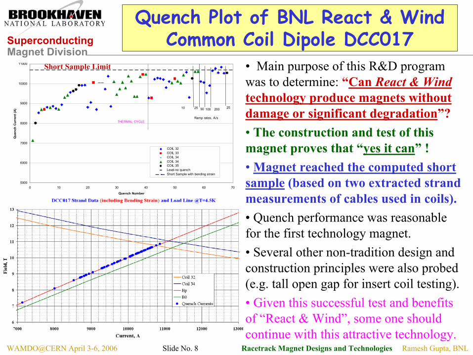
Quench Plot of BNL React & Wind Common Coil Dipole DCC017
• Main purpose of this R&D program was to determine: “Can React & Windtechnology produce magnets without damage or significant degradation”?• The construction and test of this magnet proves that “yes it can” !• Magnet reached the computed short sample (based on two extracted strand measurements of cables used in coils).• Quench performance was reasonable for the first technology magnet.• Several other non-tradition design and construction principles were also probed (e.g. tall open gap for insert coil testing).• Given this successful test and benefits of “React & Wind”, some one should continue with this attractive technology.
Ramesh Gupta, BNLWAMDO@CERN April 3-6, 2006 Slide No. 9 Racetrack Magnet Designs and Technologies
Jc, Strain and Field in Nb3Sn
Source: J.W. Ekin, in “Filamentary A-15 Superconductors”, edited by Suenaga and Clark
A 15% drop in Jc corresponds to ~4% drop in Bss. 0.3 % strain may be acceptable for a 12 T magnet. One should place limit at 0.2% for a 14 T design.Also note that “high strain” and “high field” are not usually at the same location.
Superconducting Magnet Division
Ramesh Gupta, BNLWAMDO@CERN April 3-6, 2006 Slide No. 10 Racetrack Magnet Designs and Technologies
Bending Strain in Magnets Made with React & Wind Technology
FNAL has done a lot of systematic studies on the influence of bending strain in various wires and cables. Different wires have different bending degradation.Reducing bending degradation in Nb3Sn wire and cable will be one important area of productive research for developing high field “React & Wind” magnet technology.
BNL common coil design has bend radius of 70 mm and uses 0.8 mm wire, as compared to FNAL common coil design with 90 mm radius and 0.7 mm wire.Corresponding bending strain in wire is 0.6% in BNL and 0.4% in FNAL designs (in both cases it was effectively reduced by half - 0.3% in BNL design and 0.2% in FNAL design - by reacting cable to 2x radius drum).
Arup Ghosh used the radius of the “area of superconductor in the wire” rather than the radius of “wire” itself in the bending degradation calculations. This corresponds to even a smaller value of bending strain and the test results are consistent with that.
A ~15 T magnet should be possible with Nb3Sn “React & Wind” Technology.
Superconducting Magnet Division
Ramesh Gupta, BNLWAMDO@CERN April 3-6, 2006 Slide No. 11 Racetrack Magnet Designs and Technologies
Wind & React Vs. React & Wind
Issues Wind & React React &WindUse of “BrittleSuperconductors”
Safest bet on working with brittlesuperconductor is “Wind & React”and that’s why it is most popular forthe demonstration of successful R&Dmagnets. (+)
Biggest challenge for “React & Wind”. Brittlesuperconductor must go through all steps ofcoil manufacturing. That’s why it is the leastpopular for R&D magnets. Design andautomate all aspects of tooling to minimizepotential for such damage or degradation. (-)
Insulation and useof other materialin coil
Limited choices (insulation generallythicker) as they must withstand highreaction temperatures. (-)
Can use a variety of insulation and othermaterial in coil as none go through highreaction temperature. (+)
Length scale-upissues
Biggest challenge for “Wind &React”. Integrated build-up ofmaterial in the ends and in transitionregion as coil gets longer due todifferential thermal contraction. (-)
A successful demonstration of technology inshort magnet directly applies to long magnets,as the coil does not go through high reactiontemperature. This is the biggest strength andargument of “React & Wind” (+)
Industrialization More new technologies (-) Less new technologies (+)Biggest challengefor futuretechnology
Length scale-up issues, particularlyin magnet designs with complex ends(-).
Magnet and conductor designs to minimizethe bending strain (+).
Superconducting Magnet Division
Ramesh Gupta, BNLWAMDO@CERN April 3-6, 2006 Slide No. 12 Racetrack Magnet Designs and Technologies
Test Results of HTS Coil and Magnets
and It’s Relevance to LHC Upgrade
React & Wind appears to be must for High Temperature Superconductors (HTS) as the coil must go through very high reaction temperature (~880 K) and the reaction temperature must be kept uniform within 1/2 degree in the entire coil package.
Superconducting Magnet Division
Ramesh Gupta, BNLWAMDO@CERN April 3-6, 2006 Slide No. 13 Racetrack Magnet Designs and Technologies
Possible Application of HTS in Accelerator Magnets
Low Field, High Temperature ApplicationExample: Rare Isotope Accelerator (RIA) or Future Synchrotron Radiation Source• The system design benefits enormously from HTS because HTS offers the possibility of magnets to operate at a temperature higher than 4K (20-65 K).• Recent design developments are increasing the chances of making HTS magnets competitive to water-cooled copper magnets in many applications.
High Field, Low Temperature ApplicationExample: IR Magnets for LHC Luminosity Upgrade or Common Coil Magnets (may be in hybrid designs with Nb3Sn or Nb3Al) for LHC Energy Upgrade• At very high fields no superconductor carries as much Jc or Je as HTS does.
• In both cases, HTS magnets can tolerate a large energy deposition. • The coil temperature need not be controlled precisely. It can be allowed to increase by an order of magnitude more than that in LTS (either due to energy deposition or due to simpler cryo-system). HTS allow a few degrees, LTS a few tenth of a degrees.
Superconducting Magnet Division
Ramesh Gupta, BNLWAMDO@CERN April 3-6, 2006 Slide No. 14 Racetrack Magnet Designs and Technologies
Medium Field Superferric HTS Quad for Rare Isotope Accelerator (RIA)
• Quads in RIA’s Fragment Seperator region are subjected to huge radiations (~15 kW).
• A proper magnet design reduced this huge 15 kW to merely 130 W in cold structure.
• 130 W is still a large amount of heat load to be removed at 4 K.
• We are developing HTS magnets operating at ~30 K to remove this energy more economically.
• An R&D magnet has been built and tested with “commercially available HTS” from American Superconductor Corporation (ASC).
• Next few slides will indicate that how far along we have come with HTS technology.
• HTS seems to be ready for use in accelerator and beam line magnet applications. One should now consider it seriously for potential savings in “cost of ownership” .
Superconducting Magnet Division
Ramesh Gupta, BNLWAMDO@CERN April 3-6, 2006 Slide No. 15 Racetrack Magnet Designs and Technologies
RIA HTS Quadrupole At Various Stages of Construction and Testing
The RIA HTS model magnet has been successfully built and tested at BNL. Experiments of magnet operating with large energy depositions (tens of watts in 0.3 meter long magnet) have also been carried out.HTS coil winding with SS tape insulator
HTS coils during magnet assembly
Cold iron magnetic mirror test with six coils
Warm iron magnetic mirror test with twelve coils
Superconducting Magnet Division
Ramesh Gupta, BNLWAMDO@CERN April 3-6, 2006 Slide No. 16 Racetrack Magnet Designs and Technologies
Performance of 13 HTS Coils (Each made with ~220 meter of tape)
010203040506070
1 2 3 4 5 6 7 8 9 10 11 12 13Coil No.
Cur
rent
(@0.
1 µV
/cm
) Single Coil TestDouble Coil Test
The current at a voltage gradient of 0.1 µ V/cm (10 µ V/meter) over the total length of the coils at 77 K.
Coils can be made without damaging or degrading conductor. Also note the uniformity in performance of coils made with commercially available HTS.
Superconducting Magnet Division
Ramesh Gupta, BNLWAMDO@CERN April 3-6, 2006 Slide No. 17 Racetrack Magnet Designs and Technologies
RIA HTS Model Magnet Test Results for Various Configurations
A summary of the temperature dependence of the current in two, four, six and twelve coils in the magnetic mirror model. In each case voltage appears on the coil is closest to the pole tip. Magnetic field is approximately three times as great for six coils as it is for four coils.
More coils create more
field and hence would have lower
current carrying capacity
0
50
100
150
200
250
300
0 10 20 30 40 50 60 70 80 90 100Tempratue (K)
Cur
rent
@ 0
.1 µ
V/cm
(A)
Two CoilsFour CoilsSix CoilsTwelve Coils
Superconducting Magnet Division
Ramesh Gupta, BNLWAMDO@CERN April 3-6, 2006 Slide No. 18 Racetrack Magnet Designs and Technologies
HTS Coils and Magnet at BNL with Rutherford Cable
Cable made at LBL, reacted at Showa, tested at BNL
HTS coil wound and tested in a common coil magnet at BNL
0
500
1000
1500
2000
2500
3000
3500
4000
4500
0 1 2 3 4 5 6 7 8 9
HTS Coil Production No.
I c (4
K,s
elf f
ield
), A
mps
Ic
Earlier coils <1 kA (~2001)
Later coils 4.3 kA (10/03)
Self-field <0.05 T
Self-field ~ 1.85 T
Modern HTS cables, coils & magnets can carry a significant current.
Superconducting Magnet Division
Ramesh Gupta, BNLWAMDO@CERN April 3-6, 2006 Slide No. 19 Racetrack Magnet Designs and Technologies
Superconductors for High Field Magnets
Graph below compares the critical current density (Jc) for various superconductors as a function of field.
Also for machine design purpose, one must consider the operating field and not the field on the conductor. This means that one should also include peak enhancement and some operating margin. The two usually add to about 20% more to the design field.
Performance of 0.8 mm dia wire
100
1000
10000
0 2 4 6 8 10 12 14 16 18 20
B(T)
Jc(A
/mm
2)
Nb3Sn (4.2K)
BSCCO2212 (4.2K)
NbTi (1.8K)
NbTi (4.2K)
As of year 2000
Thus for a 15 T magnet, compare conductor performance at 18 T.
However, for magnet design calculations purpose, one must compare the overall current density in coil which includes, copper, insulator, etc.
Superconducting Magnet Division
Ramesh Gupta, BNLWAMDO@CERN April 3-6, 2006 Slide No. 20 Racetrack Magnet Designs and Technologies
Overall Current Density in Commercially Available High Field Superconductors
Data used in making plots (details)Nb3Sn: Wire/cable specified for present LARP Quad (Jc@12T=2400A/mm2, Cu/Sc=1.0, insulation 250 micron per turn)
HTS: 155A at 77K – can be ordered today from ASC Website. Scaling used for 77 K to 4K. Kapton/SS tape for insulation.
Overall current density as a function of design field in commercial high field superconductors
Commercially available HTS now offer more current density than Nb3Sn to design magnets at an operating field over 13.5 T to 14.5 T.
HTS should now be considered in those high field magnet applications where the performance and not the cost is the driver.
0100200300400500600700800900
1000
8 9 10 11 12 13 14 15 16 17Bdesign (T)
Jo(A
/mm
2)
Nb3Sn
BSCCO2223 (4.2K)Field perpendicular
BSCCO2223 (4.2K)Field parallel
Design operating field is generally 20% over the conductor field due to peak field and margin.
Ramesh Gupta, BNLWAMDO@CERN April 3-6, 2006 Slide No. 21 Racetrack Magnet Designs and Technologies
Usable Conductors Performance in Near Future High Field Superconductors
So what’s in future (speculating improvements in a few years)?Stable Nb3Sn with Jc(12T) may be available at 2800 A/mm2
instead of 2400 A/mm2 used in previous slide.
BSCCO 2223 (1G) performance of sorted wires may improve to 180 A (which is ~10% over 165 A already achieved at ASC with sufficient frequency), instead of 155 A used in comparison.
The two gives about the same relative improvement in Jo (J-overall). The field at which HTS Jo becomes more than Nb3Sn does not change much.
Courtesy: Garry Ferguson, American Superconductor
Superconducting Magnet Division
Ramesh Gupta, BNLWAMDO@CERN April 3-6, 2006 Slide No. 22 Racetrack Magnet Designs and Technologies
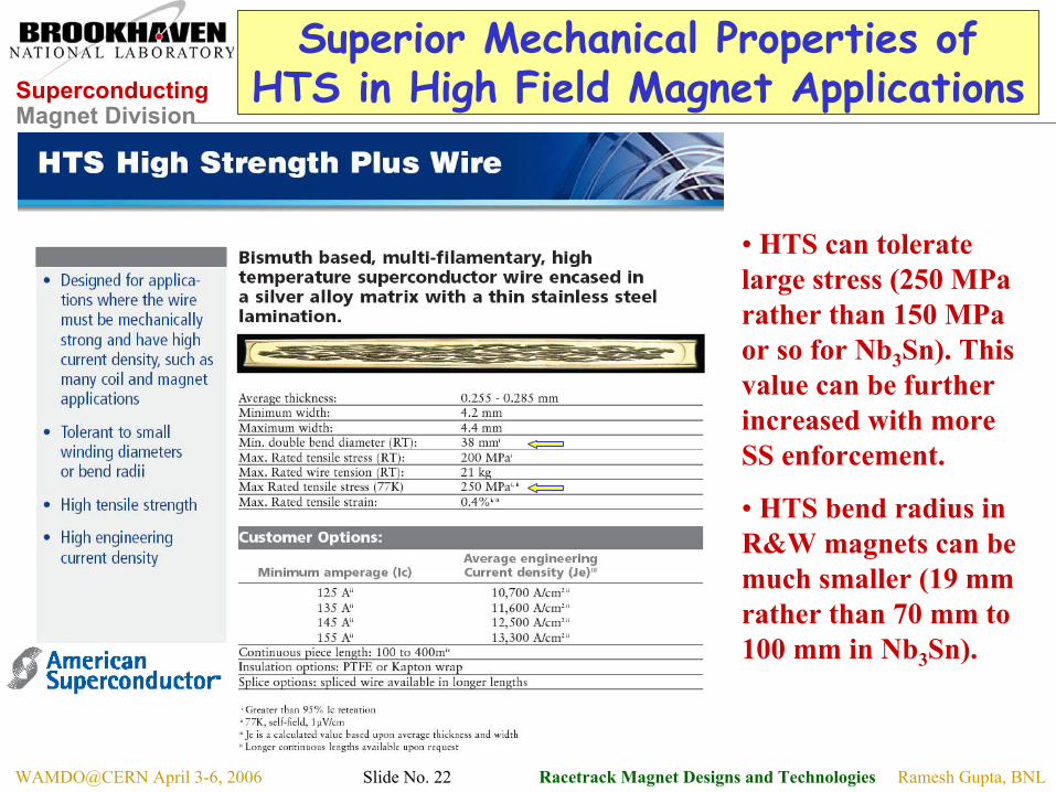
Superior Mechanical Properties of HTS in High Field Magnet Applications
• HTS can tolerate large stress (250 MParather than 150 MPaor so for Nb3Sn). This value can be further increased with more SS enforcement.
• HTS bend radius in R&W magnets can be much smaller (19 mm rather than 70 mm to 100 mm in Nb3Sn).
Superconducting Magnet Division
Ramesh Gupta, BNLWAMDO@CERN April 3-6, 2006 Slide No. 23 Racetrack Magnet Designs and Technologies
Availability of Second Generation (2G) HTS (YBCO) in Sufficient Quantities
• Second generation (2G) HTS (YBCO) is now starting to become available in larger quantities. For example, even now it can be purchased in 100 m length from American Superconductor. Based on the length scale-up approach used, much larger lengths are expected to become available in future.
• The cost of second generation wire (tape) is projected to be much smaller than the cost of first generation HTS (BSCCO).
• Second generation wire also has some superior technical properties. In particular incorporation of nano-dots dramatically improves its “in-field” characteristics/performance.
Superconducting Magnet Division
Ramesh Gupta, BNLWAMDO@CERN April 3-6, 2006 Slide No. 24 Racetrack Magnet Designs and Technologies
Racetrack Coil Magnet Designs
• Common Coil Magnet Design
• Open Midplane Dipole Design
• Modular Quadrupole Design
Note:These designs are technology independent. That means one can either use “Wind & React” or “React & Wind” technology with these designs.
Superconducting Magnet Division
Ramesh Gupta, BNLWAMDO@CERN April 3-6, 2006 Slide No. 25 Racetrack Magnet Designs and Technologies
Common Coil Design• Simple 2-d geometry with large bend
radius (determined by spacing between two apertures, rather than aperture itself)
• Conductor friendly (no complex 3-d ends, suitable for brittle materials such as Nb3Sn, Nb3Al and HTS)
• Compact (quadrupole type cross-section, field falls more rapidly)
• Block design (for handling large Lorentz forces at high fields)
• Combined function magnets possible• Efficient and methodical R&D due to
simple & modular design• Minimum requirements on big
expensive tooling and labor• Lower cost magnets expected
Beam #1
Coil #1
Coil #2Main Coils of the Common Coil Design
Beam #2
Superconducting Magnet Division
Ramesh Gupta, BNLWAMDO@CERN April 3-6, 2006 Slide No. 26 Racetrack Magnet Designs and Technologies
Lorentz Forces in High Field Magnets(Cosine Theta and Common Coil)
In the common coil design, geometry and Lorentz forces (mostly horizontal) are such that the impregnated modules move as a block. Therefore, the common coil geometry minimizes the internal motion and that should reduce the chance of quench or damage.
In cosine theta geometry the two side of the coil cannot move as a block. Therefore, the Lorentz forces put strain on the conductor at the ends and that may cause premature quenches.
Superconducting Magnet Division
Ramesh Gupta, BNLWAMDO@CERN April 3-6, 2006 Slide No. 27 Racetrack Magnet Designs and Technologies
Progress in Field Quality (Geometric Harmonics)
Normal Harmonics at 10 mm in the units of 10-4
-1.0-0.8-0.6-0.4-0.20.00.20.40.60.81.0
0 2 4 6 8 10 12 14
(from 1/4 model)
Typical Requirements: ~ part in 104, we have part in 105
The above model uses all flat coils.
MAIN FIELD: -1.86463 (IRON AND AIR):
b 1: 10000.000 b 2: 0.00000 b 3: 0.00308 b 4: 0.00000 b 5: 0.00075 b 6: 0.00000 b 7: -0.00099 b 8: 0.00000 b 9: -0.01684 b10: 0.00000 b11: -0.11428 b12: 0.00000 b13: 0.00932 b14: 0.00000 b15: 0.00140 b16: 0.00000 b17: -0.00049 b18: 0.00000
Question: Can a racetrack coil configuration with a geometry that does not necessarily look like “cosine theta”, produce designs with low field harmonics?
Superconducting Magnet Division
Ramesh Gupta, BNLWAMDO@CERN April 3-6, 2006 Slide No. 28 Racetrack Magnet Designs and Technologies
An Example of End Optimization with ROXIE (iron not included)
Poor field quality, excessive conductor requirements, etc. are myth about block designs. A properly designed block dipole uses similar conductor and gives similar field quality as cosine theta does.
Superconducting Magnet Division
Ramesh Gupta, BNLWAMDO@CERN April 3-6, 2006 Slide No. 29 Racetrack Magnet Designs and Technologies
20+ T Hybrid Common Coil Dipole Design for LHC Energy Upgrade
Central Field = 20+ T
Inner coils:HTS (>20 T)
Outer coils:Nb3Sn (<15 T)
One quadrant of model (1/2 of one of two apertures)
Superconducting Magnet Division
Ramesh Gupta, BNLWAMDO@CERN April 3-6, 2006 Slide No. 30 Racetrack Magnet Designs and Technologies
Common Coil Magnet System (Injector + Main Ring) for the LHC Energy Upgrade
Inject in the iron dominated aperture at low field and accelerate to medium field
Transfer to conductor dominated aperture at medium field and then accelerate to high field
Iron dominated apertureGood at low field (0.56-1.5T)
Conductor dominated apertureGood at high field (1.5-20 T)
Compact size
A 4-in-1 magnet for
a 2-in-1 machine
Injection at low field in iron dominated aperture should solve the large persistent current problems associated with Nb3Sn
*Concept developed while I was at LBL
Due to lack of space for an additional ring in the LHC tunnel, LHC ring can not be used as an injector and must be removed for LHC energy upgrade. The proposed 4-in-1 magnet concept allows the same magnet to be used for both injector and main ring. It also provides significant savings in cost over the separate injector case.
Superconducting Magnet Division
Ramesh Gupta, BNLWAMDO@CERN April 3-6, 2006 Slide No. 31 Racetrack Magnet Designs and Technologies
Common Coil Magnet System (Economical and Technical Advantages)
• Large Dynamic Range~ 40 instead of usual 8-20.
May eliminate the need of the second largest ring. Significant saving in the cost of LHC accelerator complex.
• Good Field Quality (throughout)
Low Field: Iron DominatedHigh Field: Conductor Dominated.
Good field quality from injection to highest field with a single power supply.
• Possible Reduction in High Field Aperture
Beam is transferred, not injected – no wait, no snap-back.
Minimum field seen by high field aperture is ~1.5 T and not ~0.5 T.
The basic machine criteria are changed!Reduce high field aperture, say to 25 mm?
Reduction in high field aperture =>reduction in conductor & magnet cost.
• Compact Magnet SystemAs compared to two machines with
several apertures.
Superconducting Magnet Division
Ramesh Gupta, BNLWAMDO@CERN April 3-6, 2006 Slide No. 32 Racetrack Magnet Designs and Technologies
A Combined Function Common Coil Magnet System for Lower Cost VLHC
High Energy Booster
Main Ring
A 4-in-1 magnet for
a 2-in-1 machine
In a conventional superconducting magnet design, the right side of the coil returns on the left side. In a common coil magnet, coil from one aperture returns to the other aperture instead.
• A combined magnet design is possible as the coils on the right and left sides are different.
• Therefore, combined function magnets are possible for both low and high field apertures.
• Note: Only the layouts of the higher energy and lower energy machines are same. The “Lattice” of the two rings could be different.
Superconducting Magnet Division
Ramesh Gupta, BNLWAMDO@CERN April 3-6, 2006 Slide No. 33 Racetrack Magnet Designs and Technologies
Open Midplane Dipole for
LHC IR Upgrade in Dipole First Optics
Superconducting Magnet Division
Ramesh Gupta, BNLWAMDO@CERN April 3-6, 2006 Slide No. 34 Racetrack Magnet Designs and Technologies
Special Considerations for LHC Upgrade Dipole Design in “Dipole First Optics”
High luminosity (1035) Interaction Regions (IR) present a hostile environment for superconducting magnets by throwing ~9 kW of power from each beam
This raises two basic challenges:
• How to design magnets that can survive these large heat and radiation loads against pre-mature quench and life time of magnet components?
• What is the cost of removing these large heat loads both in terms of “new infrastructure” and “operating cost” ?
In the proposed “Open Midplane Design” the particle spray from IP deposits most of its energy in a warm absorber instead in superconducting coils or other cold structures.
Superconducting Magnet Division
Ramesh Gupta, BNLWAMDO@CERN April 3-6, 2006 Slide No. 35 Racetrack Magnet Designs and Technologies
A True Open Midplane Design
Particle spray from IP (mostly at midplane), passes through an open region to a warm (~80 K) absorber sufficiently away from the coil without hitting superconducting coils or any structure near it.
In earlier “open midplane designs”, although there was “no conductor” at the midplane, but there was some “other structure” between the upper and lower halves of the coil. Secondary showers from thatother structure deposited a large amount of energy on the coils.
Therefore, earlier designs did not work so well in protecting superconducting coils from energy deposition.
By open midplane, we mean truly open midplane:
Support Structure, SS (cold)
Lorentz Forces: Vertical: down Horizontal: out
Lorentz Forces: Vertical: up (small)Horizontal: out
A large amount of particles coming from high luminosity IP deposit energy in a warm (or 80 K) absorber, that is inside the cryostat. Heat is removed efficiently at higher temperature.
Yoke (cold)
Beam
Particle Spray from IP
Superconducting Magnet Division
Ramesh Gupta, BNLWAMDO@CERN April 3-6, 2006 Slide No. 36 Racetrack Magnet Designs and Technologies
Open Midplane Dipole DesignChallenges
In usual cosine theta or block coil designs, there are large attractive forces between upper and lower coils. How can these coils hang in air with no structure in between? The ratio of peak field in the coil to the design field in the aperture appears to become large for large midplane gaps.The large gap at midplane appears to make obtaining good field quality a challenging task. Gap requirements are such that a significant portion of the cosine theta, which normally plays a major role in generating field and field quality, must be taken out from the coil structure.
Could there be a solution that can satisfies all of above requirements?
With such basic challenges in place, don’t expect the design to look like what we are used to seeing in conventional magnets.
Superconducting Magnet Division
Ramesh Gupta, BNLWAMDO@CERN April 3-6, 2006 Slide No. 37 Racetrack Magnet Designs and Technologies
Challenge #1: Lorentz Forces between coils A new and major consideration in design optimization
Since there is no downward force on the lower block (there is slight upward force), we do not need much support below if the structure is segmented. The support structure can be designed to deal with the downward force on the upper block using the space between the upper and the lower blocks.
In conventional designs the upper and lower coils rest (react) against each other. In a truly open midplane design, the target is to have no structure between upper and lower coils. Structure generates large heat loads and the goal is to minimize them.
Zero vertical force line
Lore
ntz
forc
e de
nsity
(Ver
tical
)
Original Design New Design Concept to navigate Lorentz forces
Superconducting Magnet Division
Ramesh Gupta, BNLWAMDO@CERN April 3-6, 2006 Slide No. 38 Racetrack Magnet Designs and Technologies
Challenge #2: Peak Field
Quench Field: ~16 T with Jc = 3000 A/mm2, Cu/Non-cu = 0.85
Quench Field: ~15.8 T with Jc = 3000 A/mm2, Cu/Non-cu = 1.0
Several designs have been optimized with a small peak enhancement: ~7% over Bo
Superconducting Magnet Division
Ramesh Gupta, BNLWAMDO@CERN April 3-6, 2006 Slide No. 39 Racetrack Magnet Designs and Technologies
Challenge #3: Field Quality
Coil-to-coil gap in this design = 34 mm (17 mm half gap)Horizontal aperture = 80 mm⇒ Vertical gap is > 42% of horizontal aperture (midplane angle: 23o)
This makes obtaining high field and high field quality a challenging task !One quadrant of the design
0
0.2
0.4
0.6
0.8
1
1.2
0 10 20 30 40 50 60 70 80 90
What part of cosine(θ) is left in that famous cosine(θ) current distribution?
We did not let prejudices come in our way of optimizing coil - e.g. that the coil must create some thing like cosine theta current distribution !
Superconducting Magnet Division
Ramesh Gupta, BNLWAMDO@CERN April 3-6, 2006 Slide No. 40 Racetrack Magnet Designs and Technologies
Field Harmonics and Relative Field Errors in an Optimized Design
Proof: Good field quality design can be obtained in such a challenging design:(Beam @ x=+/- 36 mm at far end)(Max. radial beam size: 23 mm)Geometric Field Harmonics:
Area where field error is <10-4
Field errors should be minimized for actual beam trajectory & beam size.It was sort of done when the design concept was being optimized by hand. Optimization programs are being modified to include various scenarios. Waiting for feed back from Beam Physicists on how best to optimize.However, the design as such looks good and should be adequate.
40 mm is ½ of horizontal coil spacing
Harmonics optimized by RACE2dOPT
Superconducting Magnet Division
Ramesh Gupta, BNLWAMDO@CERN April 3-6, 2006 Slide No. 41 Racetrack Magnet Designs and Technologies
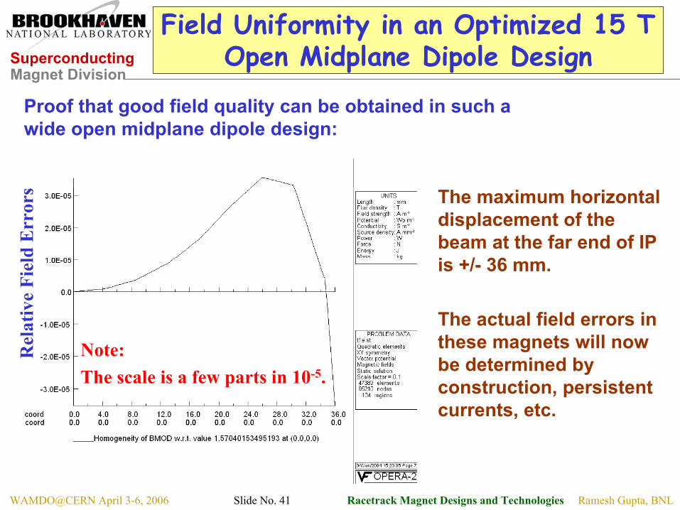
Field Uniformity in an Optimized 15 T Open Midplane Dipole Design
The maximum horizontal displacement of the beam at the far end of IP is +/- 36 mm.
The actual field errors in these magnets will now be determined by construction, persistent currents, etc.
Proof that good field quality can be obtained in such a wide open midplane dipole design:
Note: The scale is a few parts in 10-5.
Rel
ativ
e Fi
eld
Err
ors
Superconducting Magnet Division
Ramesh Gupta, BNLWAMDO@CERN April 3-6, 2006 Slide No. 42 Racetrack Magnet Designs and Technologies
Bottom Line: The Energy Deposition in this Open Midplane Dipole Design
Azimuthally averaged energy deposition iso-contours in the dipole-first IR.
Power density isocontours at the non-IP end of the D1B.
Courtesy: Nikolai Mokhov, FNAL
Superconducting Magnet Division
Ramesh Gupta, BNLWAMDO@CERN April 3-6, 2006 Slide No. 43 Racetrack Magnet Designs and Technologies
Energy Deposition Summary (Nikolai Mokhov 04/05)
Superconducting Magnet Division
Ramesh Gupta, BNLWAMDO@CERN April 3-6, 2006 Slide No. 44 Racetrack Magnet Designs and Technologies
A number of designs were investigated. Here is a Summary:
Superconducting Magnet Division
Ramesh Gupta, BNLWAMDO@CERN April 3-6, 2006 Slide No. 45 Racetrack Magnet Designs and Technologies
Modular Quadrupole Design for
A Possible LHC IR Upgrade
Superconducting Magnet Division
Ramesh Gupta, BNLWAMDO@CERN April 3-6, 2006 Slide No. 46 Racetrack Magnet Designs and Technologies
Modular Quadrupole Design Concepts
In addition to b6, b10, b14 , …, one also gets a6, a10, a14 ,… These harmonics need to be minimized.NOTE: The design needs about twice the conductor. But for a few high performance magnets, conductor cost is only a fraction of overall magnet development cost.
Type A: Simpler
This is not 8 fold symmetric.
Type B: Symmetric
No skew harmonics due to symmetry. Relatively more complex structure. May have lower peak field. Note peak field is not a major concern for HTS.
Superconducting Magnet Division
Ramesh Gupta, BNLWAMDO@CERN April 3-6, 2006 Slide No. 47 Racetrack Magnet Designs and Technologies
Previous Racetrack Designs(Considered for LHC upgrade or VLHC)
BNL designs for VLHC(ASC’02)
F║F┴
0 20 40 60 80 100 120
LBL
FNAL
None of these
designs were efficient in generating
high gradient
Peak Field
Field for gradient
Superconducting Magnet Division
Ramesh Gupta, BNLWAMDO@CERN April 3-6, 2006 Slide No. 48 Racetrack Magnet Designs and Technologies
Efficient Design to Create Gradient(not necessarily to minimize conductor usage)
• The key is to have conductor at or near the midplane (@ quad radius).Quadrupole is different from dipole. Gradient implies increasing field on coil as one moves outward within the aperture. We loose substantially if conductor at midplane does not determine the field gradient.
OPERA2d model of the octant of a 2 layer, 90 mm aperture LARP “Modular Quadrupole Design”.Je = 1000 A/mm2 generates a gradient of ~284 T/m.
This is similar to what is obtained in competing cosine theta designs.
An octant
Quadrant
Superconducting Magnet Division
Ramesh Gupta, BNLWAMDO@CERN April 3-6, 2006 Slide No. 49 Racetrack Magnet Designs and Technologies
3-Layer Design for Higher Gradient
Relative increase in transfer function (in 3 layer design, as compared to in 2 layer) : ~28%
0.02310.001814
0.00000.000018
0.00750.000610
-0.0015-0.00496
bnann
NOTE: The 2-d harmonics are essentially zero(within construction errors).
Field harmonics optimized with RACE2DOPT at 30 mm Ref. radius (in 10-4 units at 2/3 of coil radius).
Harmonics optimized by RACE2dOPT
Superconducting Magnet Division
Ramesh Gupta, BNLWAMDO@CERN April 3-6, 2006 Slide No. 50 Racetrack Magnet Designs and Technologies
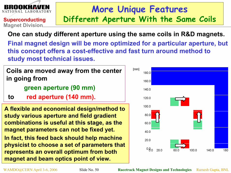
More Unique FeaturesDifferent Aperture With the Same Coils
One can study different aperture using the same coils in R&D magnets.Final magnet design will be more optimized for a particular aperture, but this concept offers a cost-effective and fast turn around method to study most technical issues.
Coils are moved away from the center in going from
green aperture (90 mm)to red aperture (140 mm).
A flexible and economical design/method to study various aperture and field gradient combinations is useful at this stage, as the magnet parameters can not be fixed yet. In fact, this feed back should help machine physicist to choose a set of parameters that represents an overall optimum from both magnet and beam optics point of view.
Superconducting Magnet Division
Ramesh Gupta, BNLWAMDO@CERN April 3-6, 2006 Slide No. 51 Racetrack Magnet Designs and Technologies
Benefits of Modular DesignSimple, Fast, Flexible & Cost-effective
• Design is consisted of simple, flat, stackable, racetrack coil modules• Positive experience with common coil program• Fast and cost effective to start and to carry out systematic R&D• Large variations in cable, coil and magnet parameters can be accommodated (such deviations are encountered during R&D phase)
• More unique R&D features for “proof-of-principle” magnets• To increase field gradient by simply adding more coil modules• To increase aperture move coils further out. This should help determine aperture and field gradient combination for beam optics by building and demonstrating a magnet at an early stage. • It allows a broad-based magnet R&D program, as high gradient modular quadrupole, common coil dipole, open midplane dipole, etc.-all can be built and tested using the same basic coil modules.
The support structures need to be designed to accommodate such provisions or it may be better to design separate structures for different applications.
Superconducting Magnet Division
Ramesh Gupta, BNLWAMDO@CERN April 3-6, 2006 Slide No. 52 Racetrack Magnet Designs and Technologies
Possible Evolution of BNL Racetrack Coil Program to Racetrack Design & Technology Study Program
• BNL is building Nb3Sn racetrack coils as a part of LARP magnet program.
• The coils with flat racetrack geometry are being built because they are simpler and offer a better likelihood of initial success.
• At present the BNL program is only a “coil program” with no path to any “LARP magnet design” directly attached to it.
• However, this “coil program” could evolve towards a limited examination of future designs and/or technology.
• In order to do above, the minimum coil bend radius must be increased. At present the bend radius is too small to be useful.
Superconducting Magnet Division
Ramesh Gupta, BNLWAMDO@CERN April 3-6, 2006 Slide No. 53 Racetrack Magnet Designs and Technologies
Summary• Racetrack coil geometry offers a good likelihood of success in making magnets with brittle conductors due to its simple, 2-d geometry.
• A number of racetrack coil magnet designs with good field quality have been developed. Few examples: common coil dipole, open midplane dipole, modular high gradient quadrupole, common coil magnet system. • “React & Wind” approach with racetrack coil geometry offers a viable and attractive option for making “long” magnets with brittle conductors. • Test results of BNL “React & Wind” common coil dipole shows that one can successfully build magnets using “React & Wind” Technology. • Present day HTS provides higher engineering (overall) current density than Nb3Sn in designing magnets that must operate above ~14 T. • Racetrack coil magnet designs and technologies could/should be considered as a apart of LARP’s broad magnet development program.• BNL racetrack coil program can be evolved to study some of these racetrack coil designs and magnet technologies.