26
Rack Air Distribution Unit ACF001 Installation, Operation, and Maintenance

Rack Air Distribution Unit
ACF001
Installation, Operation,and Maintenance
Contents
General Information.................................................1Introduction . . . . . . . . . . . . . . . . . . . . . . . . . . . . . . . . . . . 1
Features . . . . . . . . . . . . . . . . . . . . . . . . . . . . . . . . . . . . . . 1
Safety Information. . . . . . . . . . . . . . . . . . . . . . . . . . . . . . . . . . . 2
Before You Begin . . . . . . . . . . . . . . . . . . . . . . . . . . . . . . . . . . . 3Inventory . . . . . . . . . . . . . . . . . . . . . . . . . . . . . . . . . . . . . 3
Receiving inspection . . . . . . . . . . . . . . . . . . . . . . . . . . . . . 3
Overview . . . . . . . . . . . . . . . . . . . . . . . . . . . . . . . . . . . . . . . . . 4Tools required . . . . . . . . . . . . . . . . . . . . . . . . . . . . . . . . . . 4
Installation overview . . . . . . . . . . . . . . . . . . . . . . . . . . . . . 4
Equipment placement . . . . . . . . . . . . . . . . . . . . . . . . . . . . 5
Installation...............................................................6
Guides and Rails . . . . . . . . . . . . . . . . . . . . . . . . . . . . . . . . . . . . 6Mounting rail modifications for shallow vertical rail spacing . . . 7
Bellows and Ducts . . . . . . . . . . . . . . . . . . . . . . . . . . . . . . . 9
Duct assembly . . . . . . . . . . . . . . . . . . . . . . . . . . . . . . . . . 12
Cutting an opening in the floor tile . . . . . . . . . . . . . . . . . . 13
Bellows installation . . . . . . . . . . . . . . . . . . . . . . . . . . . . . 14
Fan Assembly . . . . . . . . . . . . . . . . . . . . . . . . . . . . . . . . . . . . . 15Blanking plate installation . . . . . . . . . . . . . . . . . . . . . . . . 16
Other openings . . . . . . . . . . . . . . . . . . . . . . . . . . . . . . . . 16
Connecting to the power supply . . . . . . . . . . . . . . . . . . . . 17
Replacing the perforated floor tile . . . . . . . . . . . . . . . . . . . 17
Rack Air Distribution Unit i
Operation and Maintenance .................................. 18
Start-up . . . . . . . . . . . . . . . . . . . . . . . . . . . . . . . . . . . . . . . . . . 18When to use only one fan . . . . . . . . . . . . . . . . . . . . . . . . 18
Replacing the air filter . . . . . . . . . . . . . . . . . . . . . . . . . . . 19
Warranty and Service ............................................ 20Limited warranty . . . . . . . . . . . . . . . . . . . . . . . . . . . . . . 20
Warranty limitations . . . . . . . . . . . . . . . . . . . . . . . . . . . . 20
Obtaining service . . . . . . . . . . . . . . . . . . . . . . . . . . . . . . 20
Life-Support Policy ................................................. 21General policy . . . . . . . . . . . . . . . . . . . . . . . . . . . . . . . . 21
Examples of life-support devices . . . . . . . . . . . . . . . . . . . . 21
Specifications ........................................................ 22
ii Rack Air Distribution Unit

General Information
Introduction
The American Power Conversion (APC®) Rack Air Distribution Unit (ADU) works with an existing precision air conditioning system to deliver cool air to equipment contained in a NetShelter® VX or SX enclosure or other 19-inch EIA-310-D enclosure with a removable floor. The ADU, installed at the bottom of the enclosure, pulls supply air directly into the enclosure, preventing the conditioned air from mixing with warm ambient air before it reaches the equipment. Dual fans provide the increased air flow needed to cool densely-packed equipment and improve air delivery in poor static pressure areas, solving many of the heat issues facing data centers.
Features
Features of the ADU include:
• Compact size (2 U)
• Dual input connectors for redundant power
• Two fans with independent switches
• Replaceable air filter — 30% efficient by ASHRAE standard 52.1–1992
Rack Air Distribution Unit 1
Safety Information
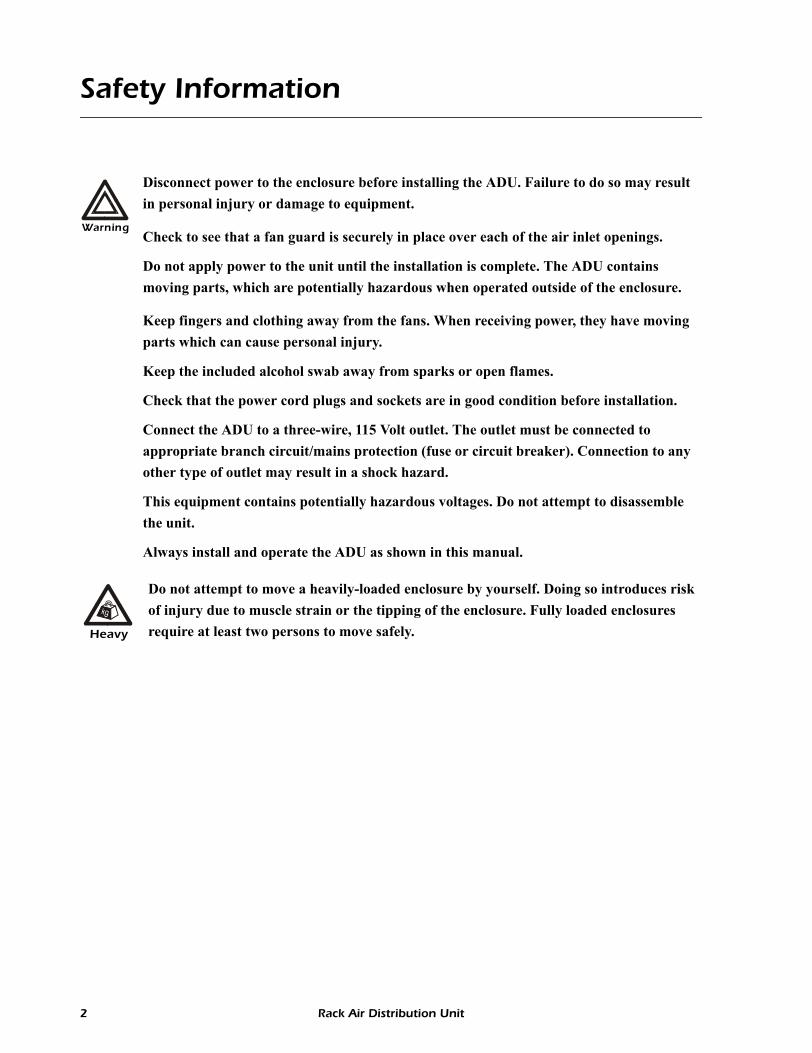
Warning
Disconnect power to the enclosure before installing the ADU. Failure to do so may result in personal injury or damage to equipment.
Check to see that a fan guard is securely in place over each of the air inlet openings.
Do not apply power to the unit until the installation is complete. The ADU contains moving parts, which are potentially hazardous when operated outside of the enclosure.
Keep fingers and clothing away from the fans. When receiving power, they have moving parts which can cause personal injury.
Keep the included alcohol swab away from sparks or open flames.
Check that the power cord plugs and sockets are in good condition before installation.
Connect the ADU to a three-wire, 115 Volt outlet. The outlet must be connected to appropriate branch circuit/mains protection (fuse or circuit breaker). Connection to any other type of outlet may result in a shock hazard.
This equipment contains potentially hazardous voltages. Do not attempt to disassemble the unit.
Always install and operate the ADU as shown in this manual.
Heavy
Do not attempt to move a heavily-loaded enclosure by yourself. Doing so introduces risk of injury due to muscle strain or the tipping of the enclosure. Fully loaded enclosures require at least two persons to move safely.
2 Rack Air Distribution Unit

Before You Begin
Inventory
Receiving inspection
Inspect the package and contents for shipping damage, and make sure that all parts were sent. Report any damage immediately to the shipping agent. Report missing contents, damage, or other problems immediately to APC or your APC reseller.
Item Description Quantity
Stop bracket 1
Left- and right-side guide and rail assembly 1 each
Accessories and fasteners:
• Caged nut• Caged nut installation tool• Screw—M6 × 12-mm Phillips pan-head• Alcohol wipes• Plastic washers
161
163
16
Power cords (NEMA 5-15) 2
Bellows 2
Blanking plate 1
Duct 1
Replaceable air filter (ACF001RF) 1
Air intake fan guards 2
Fan assembly 1
na01
93a
Rack Air Distribution Unit 3
Overview
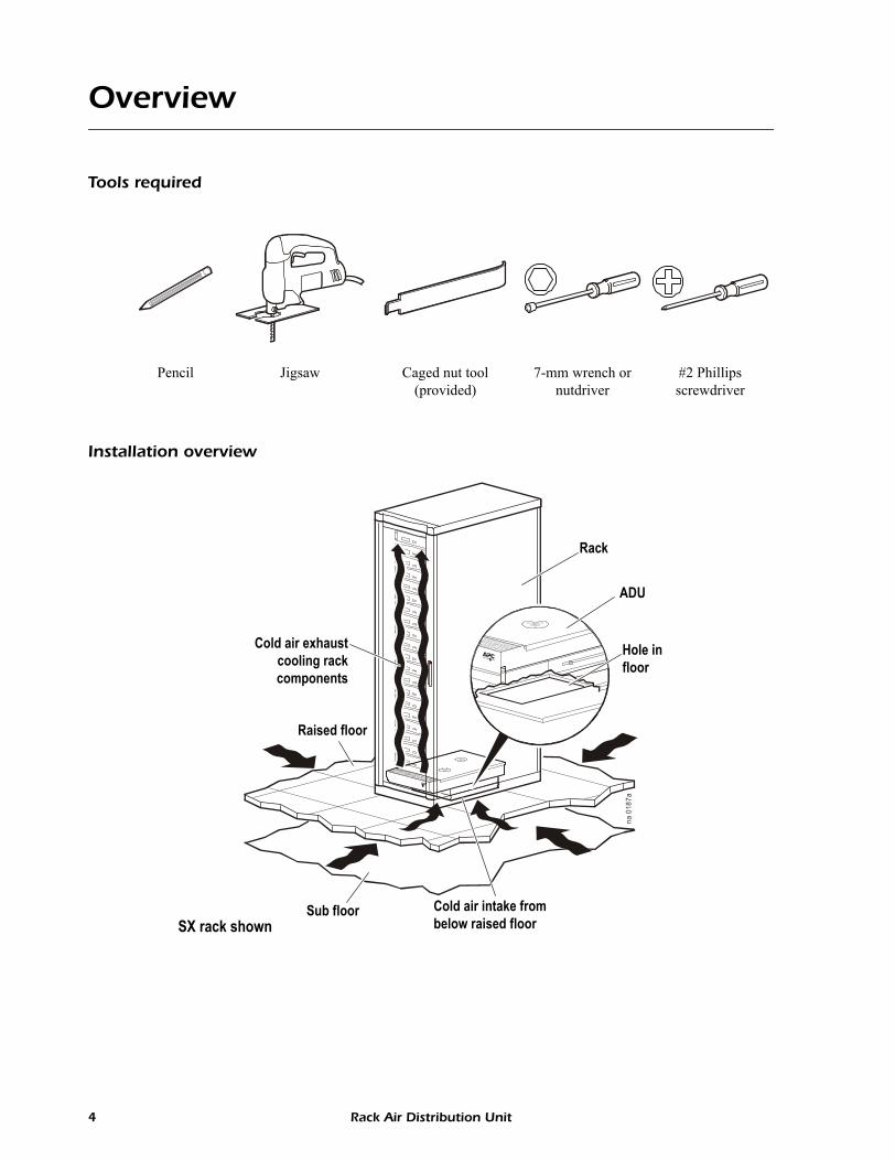
Tools required
Installation overview
Pencil Jigsaw Caged nut tool (provided)
7-mm wrench or nutdriver
#2 Phillips screwdriver
na 0
187a
Cold air exhaustcooling rackcomponents
Raised floor
Rack
ADU
Hole infloor
Cold air intake from below raised floor
Sub floorSX rack shown
4 Rack Air Distribution Unit
General Information: Overview
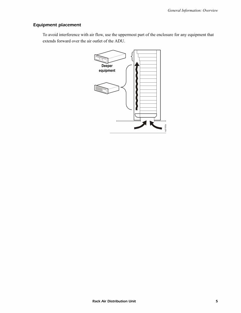
Equipment placement
To avoid interference with air flow, use the uppermost part of the enclosure for any equipment that extends forward over the air outlet of the ADU.
na01
85a
Deeperequipment
Rack Air Distribution Unit 5
Installation
Guides and Rails
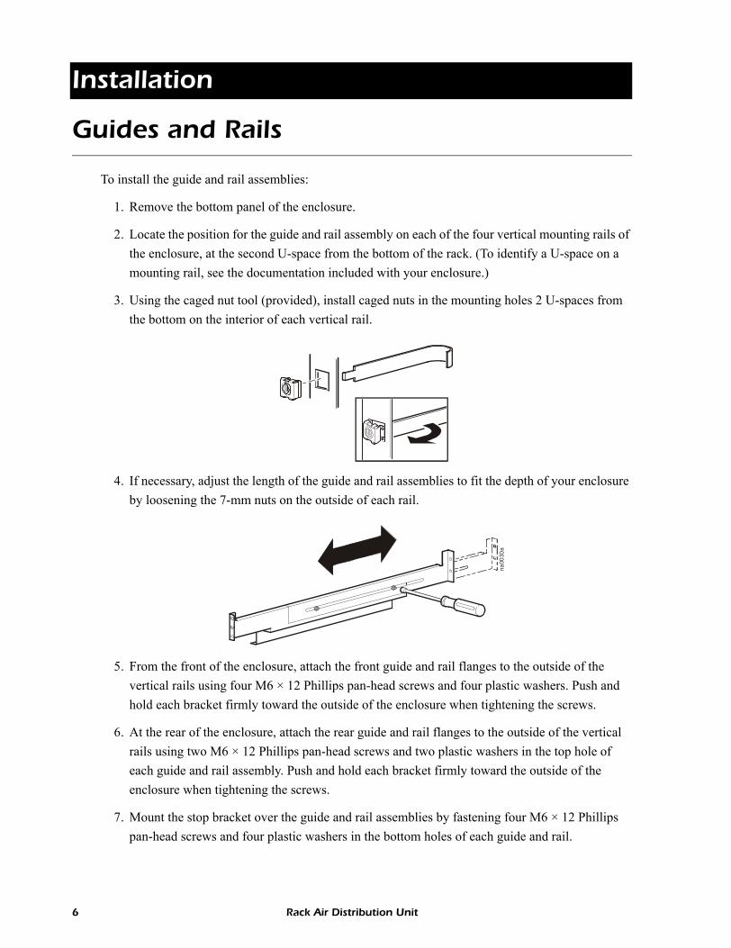
To install the guide and rail assemblies:
1. Remove the bottom panel of the enclosure.
2. Locate the position for the guide and rail assembly on each of the four vertical mounting rails of the enclosure, at the second U-space from the bottom of the rack. (To identify a U-space on a mounting rail, see the documentation included with your enclosure.)
3. Using the caged nut tool (provided), install caged nuts in the mounting holes 2 U-spaces from the bottom on the interior of each vertical rail.
4. If necessary, adjust the length of the guide and rail assemblies to fit the depth of your enclosure by loosening the 7-mm nuts on the outside of each rail.
5. From the front of the enclosure, attach the front guide and rail flanges to the outside of the vertical rails using four M6 × 12 Phillips pan-head screws and four plastic washers. Push and hold each bracket firmly toward the outside of the enclosure when tightening the screws.
6. At the rear of the enclosure, attach the rear guide and rail flanges to the outside of the vertical rails using two M6 × 12 Phillips pan-head screws and two plastic washers in the top hole of each guide and rail assembly. Push and hold each bracket firmly toward the outside of the enclosure when tightening the screws.
7. Mount the stop bracket over the guide and rail assemblies by fastening four M6 × 12 Phillipspan-head screws and four plastic washers in the bottom holes of each guide and rail.
na00
30a
6 Rack Air Distribution Unit
Installation: Guides and Rails
Rack Air Distribution Unit 7
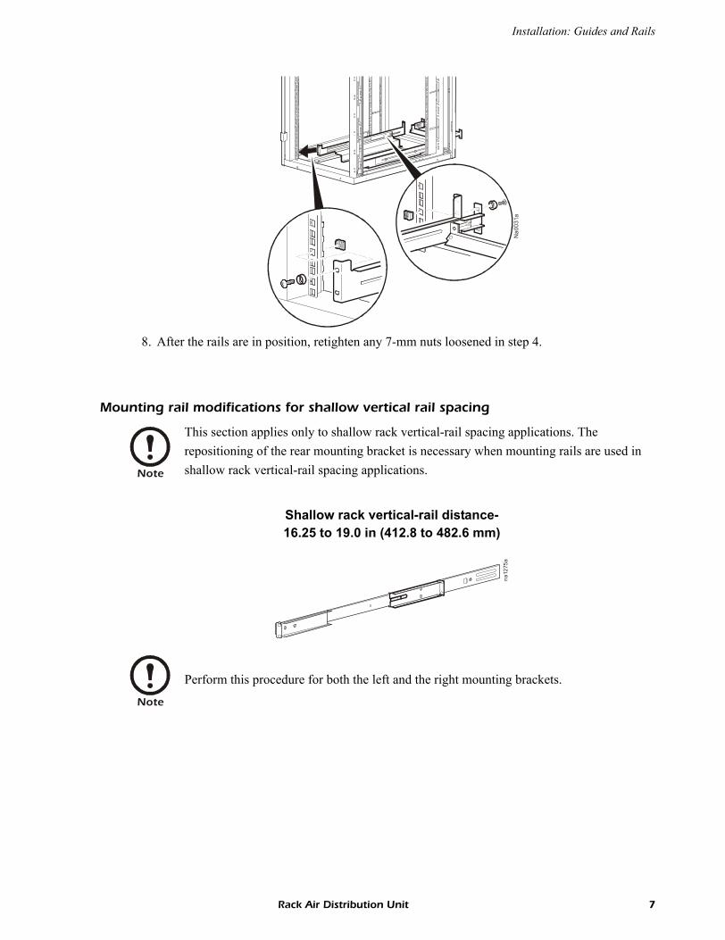
8. After the rails are in position, retighten any 7-mm nuts loosened in step 4.
Mounting rail modifications for shallow vertical rail spacing
Na0
031a
Note
This section applies only to shallow rack vertical-rail spacing applications. The repositioning of the rear mounting bracket is necessary when mounting rails are used in shallow rack vertical-rail spacing applications.
Shallow rack vertical-rail distance-16.25 to 19.0 in (412.8 to 482.6 mm)
Note
Perform this procedure for both the left and the right mounting brackets.
na12
75a
Installation:Guides and Rails
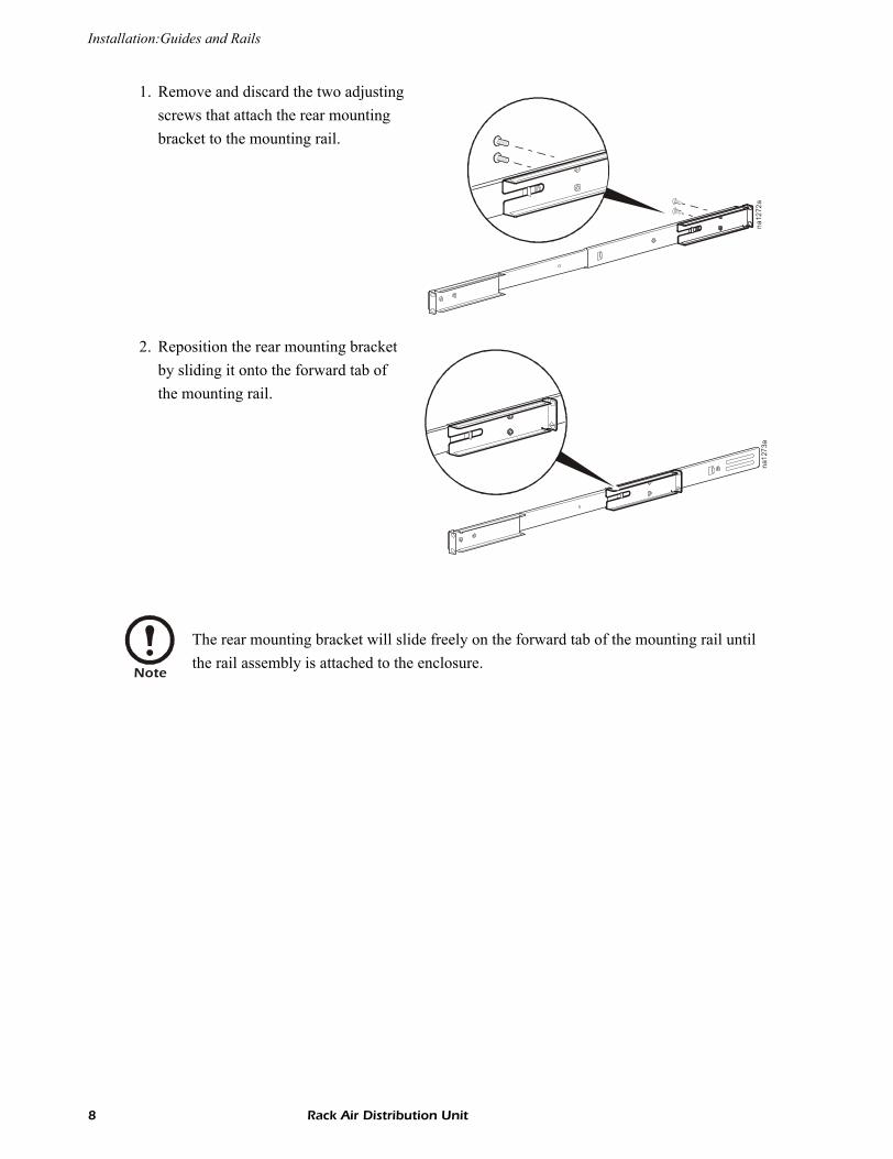
1. Remove and discard the two adjusting screws that attach the rear mounting bracket to the mounting rail.
2. Reposition the rear mounting bracket by sliding it onto the forward tab of the mounting rail.
Note
The rear mounting bracket will slide freely on the forward tab of the mounting rail until the rail assembly is attached to the enclosure.
na12
72a
na12
73a
8 Rack Air Distribution Unit
Installation: Guides and Rails
Bellows and Ducts
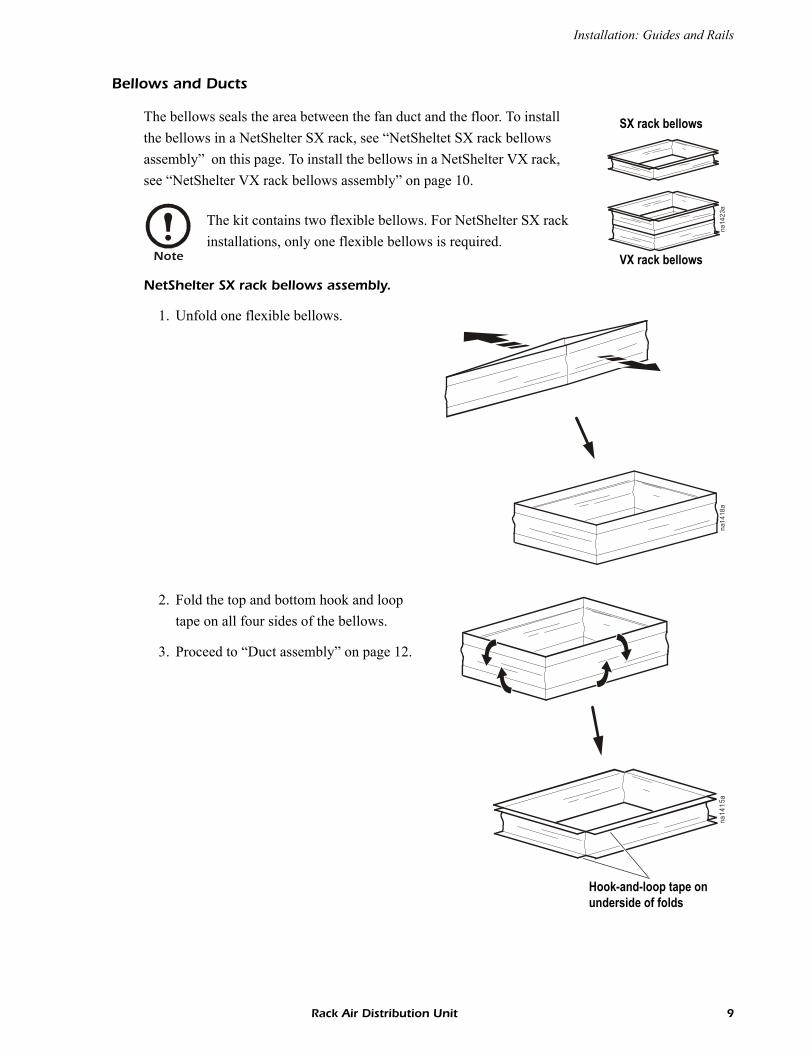
The bellows seals the area between the fan duct and the floor. To install the bellows in a NetShelter SX rack, see “NetSheltet SX rack bellows assembly” on this page. To install the bellows in a NetShelter VX rack, see “NetShelter VX rack bellows assembly” on page 10.
NetShelter SX rack bellows assembly.
1. Unfold one flexible bellows.
2. Fold the top and bottom hook and loop tape on all four sides of the bellows.
3. Proceed to “Duct assembly” on page 12.
Note
The kit contains two flexible bellows. For NetShelter SX rack installations, only one flexible bellows is required.
na14
23a
SX rack bellows
VX rack bellows
na14
18a
na14
15a
Hook-and-loop tape on underside of folds
Rack Air Distribution Unit 9

Installation:Guides and Rails
NetShelter VX rack bellows assembly.
1. Unfold both flexible bellows as shown.
2. Orient one bellows so that the hook-and-loop tape material is on the top outside edge. Fold down the top edges on all four sides of the hook-and-loop tape. This is considered the top section of the bellows.
na14
18a
na14
20a
Top section
Hook-and-loop tape on underside of folds
10 Rack Air Distribution Unit
Installation: Guides and Rails
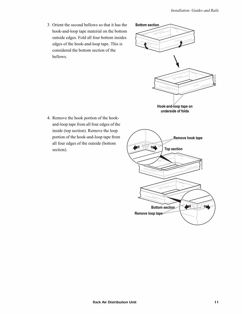
3. Orient the second bellows so that it has the hook-and-loop tape material on the bottom outside edges. Fold all four bottom insides edges of the hook-and-loop tape. This is considered the bottom section of the bellows.
4. Remove the hook portion of the hook-and-loop tape from all four edges of the inside (top section). Remove the loop portion of the hook-and-loop tape from all four edges of the outside (bottom section).
na14
21a
Bottom section
Hook-and-loop tape on underside of folds
na14
22a
Bottom section
Top section
Remove hook tape
Remove loop tape
Rack Air Distribution Unit 11
Installation:Guides and Rails
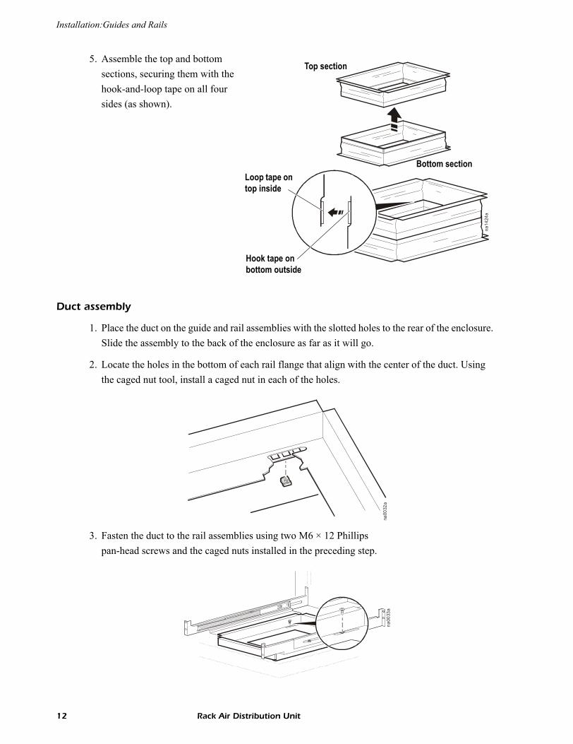
5. Assemble the top and bottom sections, securing them with the hook-and-loop tape on all four sides (as shown).
Duct assembly
1. Place the duct on the guide and rail assemblies with the slotted holes to the rear of the enclosure. Slide the assembly to the back of the enclosure as far as it will go.
2. Locate the holes in the bottom of each rail flange that align with the center of the duct. Using the caged nut tool, install a caged nut in each of the holes.
3. Fasten the duct to the rail assemblies using two M6 × 12 Phillipspan-head screws and the caged nuts installed in the preceding step.
na14
24a
Loop tape on top inside
Hook tape on bottom outside
Bottom section
Top section
na00
32a
na00
33a
12 Rack Air Distribution Unit

Installation: Guides and Rails
Cutting an opening in the floor tile
1. Using the inside edge of the duct opening as a template, mark the location for the opening to be created in the raised floor tile.
2. Move the enclosure to provide access to the floor tile.
3. Remove the floor tile and cut an opening in the tile at the location marked. Use tools that will provide a clean, accurate cut.
4. Using the supplied alcohol swab, clean the edges of the opening in the floor tile.
5. Remove the hook portions of the hook-and-loop tape from the bottom lip of the fabric portion of the duct. Remove the protective plastic that covers the adhesive. Place the tape along the perimeter of the opening, adhesive-side down.
6. Reinstall the floor tile in its original position.
7. Move the enclosure to its original position and stabilize it.
na00
34a
na00
35a
Rack Air Distribution Unit 13

Installation:Guides and Rails
Bellows installation
1. Push the bellows through the duct opening and attach the bellows to the floor using the hook-and-loop tape.
2. Pull the bellows material up through the duct opening. Remove the loop halves of the hook-and-loop tape from the top lip of the bellows. Remove the protective plastic covering the adhesive. Place the tape along the perimeter of the duct opening, adhesive-side down.
3. Attach the top lip of the bellows material to the duct perimeter using the hook-and-loop tape.na
0036
a
na14
19a
14 Rack Air Distribution Unit

Rack Air Distribution Unit 15
Fan Assembly
1. Place the filter in the filter housing of the duct so that the arrow on the filter points upward to match the intended air flow of the Air Distribution Unit.
2. With the front of the fan assembly facing the front of the enclosure, insert the rails on the sides of the fan assembly into the guides on the guide and rail assemblies.
3. Slide the fan assembly toward the rear of the enclosure until the rails lock into place.
4. Tighten all the screws holding the guide and rail assemblies to the vertical rails.
5. Close the front door of the enclosure and, from the rear, push the fan assembly fully forward until it touches the front door of the enclosure.
6. Using a 7-mm wrench or nutdriver, adjust the stop bracket to prevent the fan assembly from sliding back toward the rear of the enclosure.
na00
37a
na00
38a
na01
28a
Installation:Fan Assembly
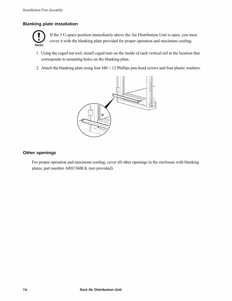
Blanking plate installation
1. Using the caged nut tool, install caged nuts on the inside of each vertical rail at the location that corresponds to mounting holes on the blanking plate.
2. Attach the blanking plate using four M6 × 12 Phillips pan-head screws and four plastic washers.
Other openings
For proper operation and maximum cooling, cover all other openings in the enclosure with blanking plates, part number AR8136BLK (not provided).
Note
If the 3 U-space position immediately above the Air Distribution Unit is open, you must cover it with the blanking plate provided for proper operation and maximum cooling.
na00
39a
16 Rack Air Distribution Unit

Installation: Fan Assembly
Connecting to the power supply
To supply power to the Air Distribution Unit:
1. Using one of the supplied power cords, insert the connector to the “A” input receptacle on the rear of the unit. Plug the other end into a UPS or other device that provides protected power.
2. To provide redundant power to the unit, use the remaining “B” receptacle to connect the Air Distribution Unit to a source of protected power.
3. Cords may be bundled and tie-wrapped to provide clearance for other components.
Replacing the perforated floor tile
The perforated floor tile in front of the enclosure containing the Air Distribution Unit can be replaced with solid floor tiles under these conditione:
• Other equipment in the vicinity is not dependent on the airflow.
• Under-floor pressure is a concern.
Replacing the perforated floor tile can increase air flow in the other areas of the data center.
ACA B
FAN1 2
na00
40a
Rack Air Distribution Unit 17
Operation and Maintenance
Start-up
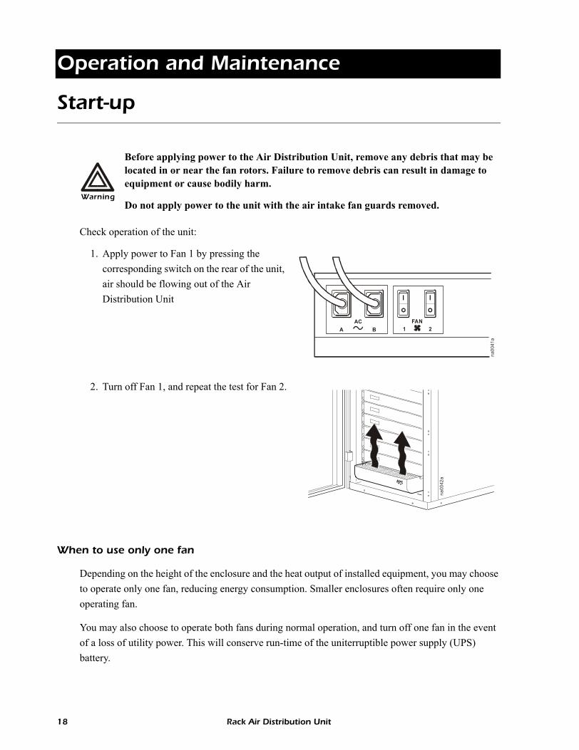
Check operation of the unit:
1. Apply power to Fan 1 by pressing the corresponding switch on the rear of the unit, air should be flowing out of the Air Distribution Unit
2. Turn off Fan 1, and repeat the test for Fan 2.
When to use only one fan
Depending on the height of the enclosure and the heat output of installed equipment, you may choose to operate only one fan, reducing energy consumption. Smaller enclosures often require only one operating fan.
You may also choose to operate both fans during normal operation, and turn off one fan in the event of a loss of utility power. This will conserve run-time of the uniterruptible power supply (UPS) battery.
Warning
Before applying power to the Air Distribution Unit, remove any debris that may be located in or near the fan rotors. Failure to remove debris can result in damage to equipment or cause bodily harm.
Do not apply power to the unit with the air intake fan guards removed.
AC FANA B 1 2
na00
41a
na00
42a
18 Rack Air Distribution Unit
Operation and Maintenance: Start-up
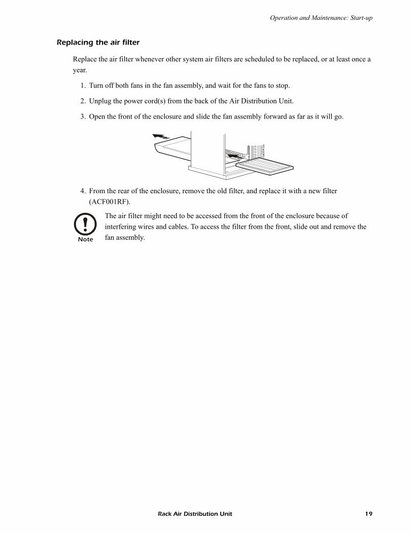
Replacing the air filter
Replace the air filter whenever other system air filters are scheduled to be replaced, or at least once a year.
1. Turn off both fans in the fan assembly, and wait for the fans to stop.
2. Unplug the power cord(s) from the back of the Air Distribution Unit.
3. Open the front of the enclosure and slide the fan assembly forward as far as it will go.
4. From the rear of the enclosure, remove the old filter, and replace it with a new filter(ACF001RF).
Note
The air filter might need to be accessed from the front of the enclosure because of interfering wires and cables. To access the filter from the front, slide out and remove the fan assembly.
na00
43a
Rack Air Distribution Unit 19
Warranty and Service
Limited warranty
APC warrants the Rack Air Distribution Unit to be free from defects in materials and workmanship for a period of two years from the date of purchase. Its obligation under this warranty is limited to repairing or replacing, at its own sole option, any such defective products. This warranty does not apply to equipment that has been damaged by accident, negligence, or misapplication or has been altered or modified in any way. This warranty applies only to the original purchaser.
Warranty limitations
Except as provided herein, APC makes no warranties, expressed or implied, including warranties of merchantability and fitness for a particular purpose. Some jurisdictions do not permit limitation or exclusion of implied warranties; therefore, the aforesaid limitation(s) or exclusion(s) may not apply to the purchaser.
Except as provided above, in no event will APC be liable for direct, indirect, special, incidental, or consequential damages arising out of the use of this product, even if advised of the possibility of such damage.
Specifically, APC is not liable for any costs, such as lost profits or revenue, loss of equipment, loss of use of equipment, loss of software, loss of data, costs of substitutes, claims by third parties, or otherwise. This warranty gives you specific legal rights and you may also have other rights, which vary according to jurisdiction.
Obtaining service
To obtain support for problems with your Rack Air Distribution Unit:0
1. Note the serial number. This is on the back of the Fan Assembly.
2. Contact Customer Support at a phone number at a phone number on the back cover of this document. A technician will try to help you solve the problem by phone.
3. If you must return the product, the technician will give you a return material authorization (RMA) number. If the warranty expired, you will be charged for repair or replacement.
4. Pack the unit carefully. The warranty does not cover damage sustained in transit. Enclose a letter with your name, address, RMA number and daytime phone number; a copy of the sales receipt; and a check as payment, if applicable.
5. Mark the RMA number clearly on the outside of the shipping carton.
6. Ship by insured, prepaid carrier to the address provided by the Customer Support technician.
20 Rack Air Distribution Unit

Life-Support Policy
General policy
American Power Conversion (APC) does not recommend the use of any of its products in the following situations:
• In life-support applications where failure or malfunction of the APC product can be reasonably expected to cause failure of the life-support device or to affect significantly its safety or effectiveness.
• In direct patient care.
APC will not knowingly sell its products for use in such applications unless it receives in writing assurances satisfactory to APC that (a) the risks of injury or damage have been minimized, (b) the customer assumes all such risks, and (c) the liability of American Power Conversion is adequately protected under the circumstances.
Examples of life-support devicesThe term life-support device includes but is not limited to neonatal oxygen analyzers, nerve stimulators (whether used for anesthesia, pain relief, or other purposes), autotransfusion devices, blood pumps, defibrillators, arrhythmia detectors and alarms, pacemakers, hemodialysis systems, peritoneal dialysis systems, neonatal ventilator incubators, ventilators (for adults and infants), anesthesia ventilators, infusion pumps, and any other devices designated as “critical” by the U.S. FDA.
Hospital-grade wiring devices and leakage current protection may be ordered as options on many APC UPS systems. APC does not claim that units with these modifications are certified or listed as hospital-grade by APC or any other organization. Therefore these units do not meet the requirements for use in direct patient care.
Rack Air Distribution Unit 21

Specifications
Model ACF001
Electrical
Power source 120 V; 60 Hz
Rated current (both fans) 2.0 A
Physical
Physical dimensions (H × W × D)
3.5 × 16.6 × 29 in(89 × 421 × 737 mm)
Weight 41 lb (19 kg)
Shipping weight 59 lb (27 kg)
Airflow Raised floor
Without filter and finger guards installed
*656 CFM
With filter and finger guards installed *503 CFM
Sound level
Both fans running
73 dB at 1 m
* When installed over standard raised floor at 0.5 in. w.g. (water column).
22 Rack Air Distribution Unit

*990-7206B*
APC Worldwide Customer Support
Customer support for this or any other APC product is available at no charge in any of the following ways:• Visit the APC Web site to access documents in the APC Knowledge Base and to submit customer
support requests.– www.apc.com (Corporate Headquarters)
Connect to localized APC Web sites for specific countries, each of which provides customer support information.
– www.apc.com/support/Global support searching APC Knowledge Base and using e-support.
• Contact an APC Customer Support center by telephone or e-mail.– Regional centers:
– Local, country-specific centers: go to www.apc.com/support/contact for contact information.
Contact the APC representative or other distributor from whom you purchased your APC product for information on how to obtain local customer support.
Direct InfraStruXure Customer Support Line (1)(877)537-0607 (toll free)
APC headquarters U.S., Canada (1)(800)800-4272 (toll free)
Latin America (1)(401)789-5735 (USA)
Europe, Middle East, Africa (353)(91)702000 (Ireland)
Japan (0) 35434-2021
Australia, New Zealand, South Pacific area (61) (2) 9955 9366 (Australia)
Entire contents © 2005 American Power Conversion. All rights reserved. Reproduction in whole or in part without permission is prohibited. APC, the APC logo, and NetShelter are
trademarks of American Power Conversion Corporation and may be registered in some jurisdictions. All other trademarks, product names, and corporate names are the property of
their respective owners and are used for informational purposes only.
990-7206B 07/2005


