104
RACO Commercial Fittings
RACO Commercial Fittings

B2
GENERAL INFORMATION - STANDARDS, 1999 NATIONAL ELECTRICAL CODE
General Information
When you need to couple, connect,fasten, or ground conduit or cables,RACO® fittings are your best answer.
Choose from specification grade malleable iron, steel, lightweight aluminum, or economical die castzinc materials. Many are UL Listed as rain-tight, concrete-tight, or liquidtight.
Product Features: RACO® Fittings
• RACO® fittings are designed to save time on the job
• Locknuts won’t slip or spin
• Hex-headed compression nuts locktight on the conduit
• Premium set screws provide reliable continuity of ground
• Insulated throats protect insulation during wire pulling
Fittings should be installed bylicensed electricians in compliancewith national and local electricalcodes.
Standards
Where applicable, RACO® productsare engineered in accordance withthe standards established byUnderwriters’ Laboratories (UL). Most products are listed by UL and also certified by the CanadianStandards Association (CSA).Dimensional data listed in this catalog is intended for general refer-ence with broad tolerance limits.
RACO® fittings generally conform toFederal Specifications and StandardsA-A-50552, A-A-50553, A-A-50563,FF-S-760A(2), NEMA FB1-1998, U.L.467, U.L. 514B, and CSA StandardC22.2 #18. Note: ANSI StandardC80-4 has been cancelled andreplaced by NEMA FB-1.
Underwriters’ Laboratories, Inc. file numbers: E195969 rigid, IMC and liquidtight fittings; E195970 EMT fittings; E195971 non-metallicsheathed cable fittings; E195972 service entrance cable fittings;E195966 armored and flexible metal cable fittings; E195973 outlet bushings and fittings; E1959753 grounding and bondingequipment; E67428 fixtures and fittings.
For Underwriters’ Laboratories, Inc. and Canadian StandardsAssociation listing marks, see RACO® product and carton labels.
Hazardous Locations
RACO® liquidtight conduit and cordconnectors listed on pages B50-B66are approved for use in hazardous locations by the National ElectricalCode. Applications and the Code ref-erence include:
Class 1 Div. 2 where volatile liquidsare handled or stored (501-4b)
Class 2 Div. 1 where combustibledust is in the air (502-4a2)
Class 2 Div. 2 where dust depositsmay accumulate (502-4b2)
Class 3 Div. 1 where easily ignitablefibers are manufactured orused (503-3a2)
Class 3 Div. 2 where easily ignitablefibers are handled or stored(503-3b)
The Code does not permit liquidtightconnectors for Class 1, Div. 1, loca-tions where volatile liquids and flam-mable gases are likely to be in the air.
For installation guidelines and to learnmore about RACO products, visit theNEMA website at http://www.nema.org.
The National Electrical ManufacturersAssociation (NEMA) website is a valuable electrical resource providingthe information you need - quickly.Standards and technical information,installation guides, industry news andeconomic trends, events/meetings, the latest electroindustry, and legislative and regulatory informationfor more than fifty-one product areasranging from arc welding to x-raymachines can be found with just a few clicks of your mouse.
NEMA, celebrating its 75th anniversary in 2001, is the leadingtrade association in the United States representing the interests of electroindustry manufacturers.Founded in 1926 and headquarterednear Washington, D.C., its 500 member companies manufacture products used in the generation, transmission and distribution, control,and end-use of electricity. Annual shipments of these products total$100 billion.
RA
CO
CO
MM
ER
CIA
L
FIT
TIN
GS
B3
GENERAL INFORMATION - STANDARDS, 1999 NATIONAL ELECTRICAL CODE
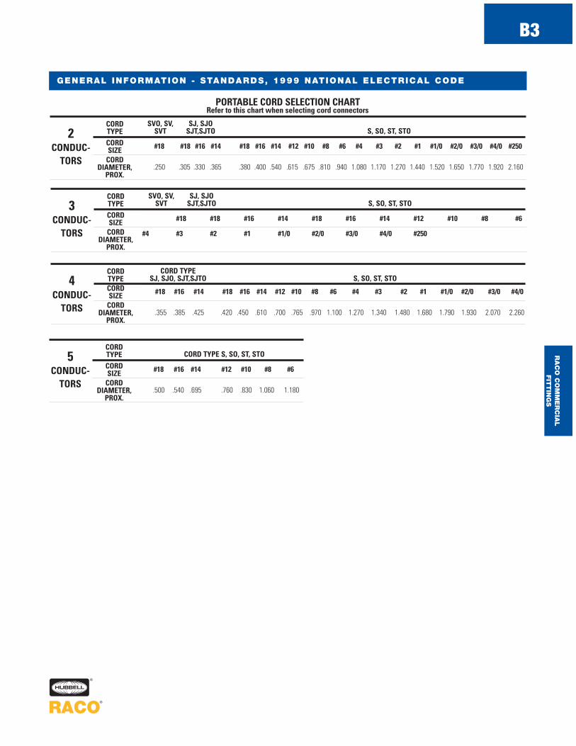
SVO, SV, SJ, SJOSVT SJT,SJTO S, SO, ST, STO
#18 #18 #16 #14 #18 #16 #14 #12 #10 #8 #6 #4 #3 #2 #1 #1/0 #2/0 #3/0 #4/0 #250
.250 .305 .330 .365 .380 .400 .540 .615 .675 .810 .940 1.080 1.170 1.270 1.440 1.520 1.650 1.770 1.920 2.160
PORTABLE CORD SELECTION CHARTRefer to this chart when selecting cord connectors
CORDTYPECORDSIZE
CORDDIAMETER,
PROX.
2CONDUC-
TORS
SVO, SV, SJ, SJOSVT SJT,SJTO S, SO, ST, STO
#18 #18 #16 #14 #18 #16 #14 #12 #10 #8 #6
#4 #3 #2 #1 #1/0 #2/0 #3/0 #4/0 #250
CORDTYPECORDSIZE
CORDDIAMETER,
PROX.
3CONDUC-
TORS
CORD TYPESJ, SJO, SJT,SJTO S, SO, ST, STO
#18 #16 #14 #18 #16 #14 #12 #10 #8 #6 #4 #3 #2 #1 #1/0 #2/0 #3/0 #4/0
.355 .385 .425 .420 .450 .610 .700 .765 .970 1.100 1.270 1.340 1.480 1.680 1.790 1.930 2.070 2.260
CORDTYPECORDSIZE
CORDDIAMETER,
PROX.
4CONDUC-
TORS
CORD TYPE S, SO, ST, STO
#18 #16 #14 #12 #10 #8 #6
.500 .540 .695 .760 .830 1.060 1.180
CORDTYPECORDSIZE
CORDDIAMETER,
PROX.
5CONDUC-
TORS
RA
CO
CO
MM
ER
CIA
L
FIT
TIN
GS

EMT FITTINGSSTEEL – SET SCREW CONNECTORS
B4
ORDERING INFORMATION - DIMENSIONS
UNINSULATED THROAT CONNECTORS
STEEL
INSULATED UNINSULATEDTHROAT THROAT TRADE UNIT SH IP UPCCATALOG CATALOG S IZE CTN . QTY. CTN . QTY. BAR CODENUMBER NUMBER
2122 2002 1/ 2" 50 500 —
2122-8 2002-8 1/ 2" 1 25
2123 2003 3/ 4" 25 250 —
2123-8 2003-8 3/ 4" 1 20
— 2004 1" 25 100 —
2124 — 1" — 25 —
2124-8 2004-8 1" 1 10
2125 2005 1-1/ 4" — 20 —
2126 2006 1-1/ 2" — 20 —
2128 2008 2" — 20 —
2160 2140 2-1/2" — 5 —
2162 2142 3" — 1 —
2164 2144 3-1/ 2" — 1 —
2166 2146 4" — 1 —
S E T S C R E W C O N N E C T O R S – S T E E L
Applications
• For use in dry locations to bond EMT conduit to a box or enclosure
• RACO® steel set screw connectorsprovide concrete-tight connectionswhen taped
• RACO® set screw connectors are suitable for applications above 600V
Product Features
• All steel construction insuresmechanical protection for the raceway
• Tri-head screws (1/2" to 1" tradesizes) may be installed using aslotted, Phillips, or Robertson head screwdriver
• 2-1/2" to 4" trade sizes are alsoUL listed for use on Rigid/IMCconduit, allowing for design andinstallation flexibility
• All components are zinc electro-plated for corrosion protection
Compliances
1/2"-2"
• – Standard 514B– C22.2 No. 18
2-1/2"-4"
• – Standard 514B
2-1/2"-4"
• – C22.2 No. 18®
®
INSULATED CONNECTORS
STEEL
RA
CO
CO
MM
ER
CIA
L
FIT
TIN
GS

EMT FITTINGSSTEEL – SET SCREW COUPLINGS
ORDERING INFORMATION - DIMENSIONS
COUPLINGSSTEEL
CATALOG UNIT SH IP UPCNUMBER TRADE S IZE CTN . QTY. CTN . QTY. BAR CODE
2022 1/ 2" 50 500 —
2022-8 1/ 2" 1 25
2023 3/ 4" 25 250 —
2023-8 3/ 4" 1 20
2024 1" 25 100 —
2024-8 1" 1 10
2025 1-1/ 4" 5 25 —
2026 1-1/ 2" — 20 —
2028 2" — 20 —
2150 2-1/ 2" — 5 —
2152 3" — 1 —
2154 3-1/ 2" — 1 —
2156 4" — 1 —
C O U P L I N G S - S T E E L
Applications
• For use in dry locations to couple two ends of EMT conduit
• RACO® steel set screw couplingsprovide concrete-tight connectionswhen taped
• RACO® set screw couplings are suitable for applications above 600V
Product Features
• All steel construction insuresmechanical protection for the raceway
• Tri-head screws (1/2" to 1" tradesizes) may be installed using aslotted, Phillips, or Robertson head screwdriver
• 2-1/2" to 4" trade sizes are alsoUL listed for use on Rigid/IMCconduit, allowing for design andinstallation flexibility
• All components are zinc electro-plated for corrosion protection
• UPC bar coded fittings are individually polybagged with a preprinted UPC-A bar code and packaged in pre-scored tear top cartons for an attractive presentation
Compliances
1/2"-2"
• – Standard 514B– C22.2 No. 18
2-1/2"-4"
• – Standard 514B
2-1/2"-4"
• – C22.2 No. 18®
®
RA
CO
CO
MM
ER
CIA
L
FIT
TIN
GS
B5

EMT FITTINGSSTEEL – COMPRESSION CONNECTORS
ORDERING INFORMATION - DIMENSIONS
Applications
• For use to bond EMT conduit to a box or enclosure
• RACO® 1/2" to 4" connectors provide concrete-tight connections
• RACO® compression connectorsare suitable for applications above 600V
Product Features
• All steel construction insuresmechanical protection for the raceway
• All components are zinc electroplated for corrosion protection
• UPC bar coded fittings are individually polybagged with a preprinted UPC-A bar code and packaged in pre-scored tear top cartons for an attractive presentation
Compliances
• – Standard 514B– C22.2 No. 18
INSULATED THROATCONNECTORS
STEEL
INSULATED UNINSULATEDTHROAT THROAT TRADE UNIT SH IP UPCCATALOG CATALOG S IZE CTN . QTY. CTN . QTY. BAR CODENUMBER NUMBER
2912 2902 1/ 2" 50 500 —
2912-8 2902-8 1/ 2" 1 25
2913 2903 3/ 4" 25 250 —
2913-8 2903-8 3/ 4" 1 20
2914 2904 1" 25 100 —
2914-8 2904-8 1" 1 10
2915 2905 1-1/ 4" 5 25 —
2916 2906 1-1/ 2" — 20 —
2918 2908 2" — 20 —
2960 2940 2-1/ 2" — 5 —
2962 2942 3" — 1 —
2964 2944 3-1/ 2" — 1 —
2966 2946 4" — 1 —
C O M P R E S S I O N C O N N E C T O R S – S T E E L
UNINSULATEDCONNECTORS
STEEL
RA
CO
CO
MM
ER
CIA
L
FIT
TIN
GS
B6

EMT FITTINGSSTEEL – COMPRESSION COUPLINGS
B7
ORDERING INFORMATION - DIMENSIONS
Applications
• For use to couple two ends of EMT conduit
• RACO® 1/2" to 4" couplings provide concrete-tight connections
• RACO® compression couplings are suitable for applications above 600V
Product Features
• All steel construction insuresmechanical protection for the raceway
• All components are zinc electroplated for corrosion protection
• UPC bar coded fittings are individually polybagged with a preprinted UPC-A bar code and packaged in pre-scored tear top cartons for an attractive presentation
Compliance
• – Standard 514B– C22.2 No. 18
CATALOG UNIT SH IP UPCNUMBER TRADE S IZE CTN . QTY. CTN . QTY. BAR CODE
2922 1/ 2" 50 500 —
2922-8 1/ 2" 1 25
2923 3/ 4" 25 250 —
2923-8 3/ 4" 1 15
2924 1" 25 100 —
2924-8 1" 1 10
2925 1-1/ 4" 5 25 —
2926 1-1/ 2" — 20 —
2928 2" — 20 —
2950 2-1/ 2" — 5 —
2952 3" — 1 —
2954 3-1/ 2" — 1 —
2956 4" — 1 —
C O U P L I N G S - S T E E L
COUPLINGS STEEL
RA
CO
CO
MM
ER
CIA
L
FIT
TIN
GS
EMT FITTINGSSTEEL – INDENTER CONNECTORS
B8
ORDERING INFORMATION - DIMENSIONS
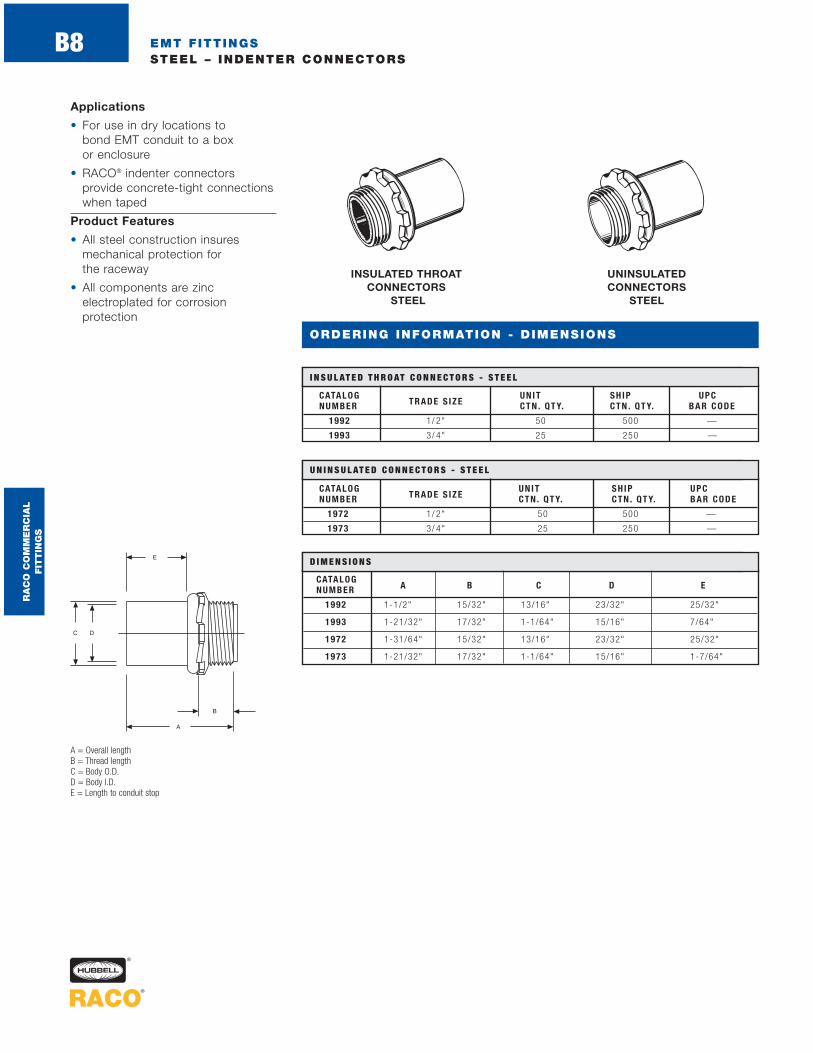
Applications
• For use in dry locations to bond EMT conduit to a box or enclosure
• RACO® indenter connectors provide concrete-tight connectionswhen taped
Product Features
• All steel construction insuresmechanical protection for the raceway
• All components are zinc electroplated for corrosion protection
UNINSULATED CONNECTORS
STEEL
INSULATED THROAT CONNECTORS
STEEL
CATALOG UNIT SH IP UPCNUMBER TRADE S IZE CTN . QTY. CTN . QTY. BAR CODE
1992 1/ 2" 50 500 —
1993 3/ 4" 25 250 —
CATALOG UNIT SH IP UPCNUMBER TRADE S IZE CTN . QTY. CTN . QTY. BAR CODE
1972 1/ 2" 50 500 —
1973 3/ 4" 25 250 —
A = Overall lengthB = Thread lengthC = Body O.D.D = Body I.D.E = Length to conduit stop
CATALOGNUMBER A B C D E
1992 1-1/2" 15/32" 13/16" 23/32" 25/32"
1993 1-21/32" 17/32" 1-1/64" 15/16" 7/64"
1972 1-31/64" 15/32" 13/16" 23/32" 25/32"
1973 1-21/32" 17/32" 1-1/64" 15/16" 1-7/64"
I N S U L AT E D T H R O AT C O N N E C T O R S - S T E E L
U N I N S U L AT E D C O N N E C T O R S - S T E E L
D I M E N S I O N S
RA
CO
CO
MM
ER
CIA
L
FIT
TIN
GS

EMT FITTINGSSTEEL – INDENTER CONNECTORS AND COUPLINGS, INDENTER TOOLS
B9
ORDERING INFORMATION - DIMENSIONS
Applications
• For use in dry locations to bond EMT conduit to a box or enclosure, or to couple twoends of EMT conduit
• RACO® indenter offset connectorsand couplings provide concrete-tight connections when taped
Product Features
• All steel construction insuresmechanical protection for the raceway
• All components are zinc electroplated for corrosion protection
COUPLINGSSTEEL
INDENTER TOOLS FORGED STEEL
OFFSET CONNECTORS
STEEL
CATALOG UNIT SH IP UPCNUMBER TRADE S IZE CTN . QTY. CTN . QTY. BAR CODE
1982 1/ 2" 50 500 —
1983 3/ 4" 25 250 —
C O U P L I N G S - S T E E L
CATALOG SHIP UPCNUMBER TRADE S IZE DESCR IP. CTN . QTY. BAR CODE
1962 1/ 2" Tool 1 —
1963 3/ 4" Tool 1 —
1961 For No. 1962 Replacement Point 10 —
1971 For No. 1963 Replacement Point 10 —
I N D E N T E R T O O L S F O R G E D - S T E E L
CATALOG UNIT SH IP UPCNUMBER TRADE S IZE CTN . QTY. CTN . QTY. BAR CODE
1932 1/ 2" — 25 —
O F F S E T C O N N E C T O R S - S T E E L
A = Overall lengthB = O.D. of bodyC = I.D. of bodyD = Thread lengthE = Amount of offsetF = Throat I.D.
CATA L O GNUMBER A B C D
1982 2" 25/32" 23/32" 31/32"
1983 2-1/4" 1-1/64" 15/16" 1-1/16"
D I M E N S I O N S
CATALOGNUMBER A B C D E F
1932 2-13/16" 53/64" 23/32" 21/64" 3/8" 5/8"
D I M E N S I O N S
A = Overall lengthB = O.D. of bodyC = I.D. of bodyD = Length to center stop
RA
CO
CO
MM
ER
CIA
L
FIT
TIN
GS

EMT FITTINGSDIE CAST – SET SCREW CONNECTORS
B10
ORDERING INFORMATION - DIMENSIONS
Applications
• For use in dry locations to economically bond EMT conduit to a box or enclosure
• RACO® die cast set screw connectors provide concrete-tightconnections when taped
• RACO® set screw connectors are suitable for applications above 600V
Product Features
• Rugged metallic construction provides mechanical protection for the raceway
• 2-1/2" to 4" trade sizes are UL Listed for use on Rigid/IMCconduit, allowing for installationflexibility
Compliance
• – Standard 514B
• – C22.2 #18®
®
A = Overall lengthB = Hub length, thread length and thread specC = Throat I.D.D = Length to conduit stopE = Screw spec (type of head, length, thread spec)F = Body O.D.G = Body I.D.
INSULATED THROATCONNECTORSDIE CAST ZINC
INSULATED UNINSULATEDCONNECTOR CONNECTOR SCREWCATALOG CATALOG A B C D E F G TYPENUM BER NUMBER
2634 2602 1-1/8" 3/8" 5/8" 11/16"10-24
15/16" 23/32"S lo t ted
x 5 /16" Rober tson
2635 2603 1-3/8" 3/8" 13/16" 15/16"10-24
1-5/32" 15/16"S lo t ted
x 5 /16" Rober tson
2636 2604 1-1/2" 15/32" 1-3/64" 15/16"10-24
1-7/16" 1-3/16"S lo t ted
x 5 /16" on l y
1/4-20Long
2637 2605 1-15/16" 19/32" 1-3/8" 1-11/32"x 7 /16"
1-13/16" 1-17/32" S lo t tedRober tson
1/4-20Long
2638 2606 2-1/4" 3/4" 1-19/32" 1-7/16"x 7 /16"
2-1/16" 1-3/4" S lo t tedRober tson
1/4-20Long
2639 2608 2-1/2" 3/4" 2-1/16" 1-3/4"x 7 /16"
2-9/16" 2-1/4" S lo t tedRober tson
2648 2640 3-1/16" 1-1/16" 2-1/2" 2"1/4-20
3-9/32" 2-7/8"S lo t ted
x 7 /16" on l y
2649 2642 3-1/4" 1-1/32" 3-5/32" 2-1/8"1/4-20
3-13/16" 3-17/32"S lo t ted
x 7 /16" on l y
2650 2644 3-9/16" 1-3/8" 3-1/2" 2-3/16"1/4-20
4-13/32" 4-1/32"S lo t ted
x 7 /16" on l y
2651 2646 3-11/16" 1-1/32" 4-5/32" 2-19/32"1/4-20
4-29/32" 4-9/16"S lo t ted
x 7 /16" on l y
D I M E N S I O N S
UNINSULATED CONNECTORSDIE CAST ZINC
INSULATED UNINSULATEDCONNECTOR CONNECTOR TRADE UNIT SH IP UPCCATALOG CATALOG S IZE CTN . QTY. CTN . QTY. BAR CODENUMBER NUMBER
2634 2602 1/ 2" 50 500 —
2635 2603 3/ 4" 25 250 —
2636 2604 1" 50 200 —
2637 2605 1-1/ 4" 25 100 —
2638 2606 1-1/ 2" 10 40 —
2639 2608 2" 5 20 —
2648 2640 2-1/ 2" — 12 —
2649 2642 3" — 12 —
2650 — 3-1/ 2" — 10 —
— 2644 3-1/ 2" — 6 —
2651 2646 4 — 6 —
S E T S C R E W C O N N E C T O R S – S T E E L
RA
CO
CO
MM
ER
CIA
L
FIT
TIN
GS
EMT FITTINGSDIE CAST - SET SCREW - COUPLINGS AND OFFSETS
ORDERING INFORMATION - DIMENSIONS
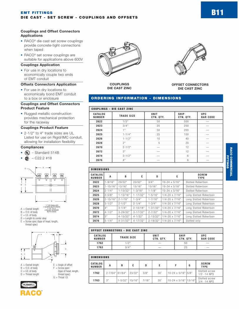
Couplings and Offset ConnectorsApplications
• RACO® die cast set screw couplingsprovide concrete-tight connectionswhen taped
• RACO® set screw couplings aresuitable for applications above 600V
Couplings Application
• For use in dry locations to economically couple two ends of EMT conduit
Offsets Connectors Application
• For use in dry locations to economically bond EMT conduit to a box or enclosure
Couplings and Offset ConnectorsProduct Feature
• Rugged metallic construction provides mechanical protection for the raceway
Couplings Product Feature
• 2-1/2" to 4" trade sizes are ULListed for use on Rigid/IMC conduit,allowing for installation flexibility
Compliances
• – Standard 514B
• – C22.2 #18®
®
COUPLINGS DIE CAST ZINC
CATALOG UNIT SH IP UPCNUMBER TRADE S IZE CTN . QTY. CTN . QTY. BAR CODE
2622 1/ 2" 50 500 —
2623 3/ 4" 25 250 —
2624 1" 50 200 —
2625 1-1/ 4" 25 100 —
2626 1-1/ 2" 10 40 —
2628 2" 5 20 —
2670 2-1/ 2" — 12 —
2672 3" — 12 —
2674 3-1/ 2" — 6 —
2676 4" — 6 —
C O U P L I N G S - D I E C A S T Z I N C
CATALOG SCREWNUM BER A B C D E T YPE
2622 1-9/16" 29/32" 23/32" 3/4" 10-24 x 5 /16" S lo t ted Rober tson
2623 1-15/16" 13/16" 15/16" 15/16" 10-24 x 5 /16" S lo t ted Rober tson
2624 2-1/4" 1-13/32" 1-3/16" 1-1/8" 10-24 x 5 /16" S lo t ted Rober tson
2625 2-5/8" 1-13/16" 1-17/32" 1-5/16" 1/4-20 x 7 /16" Long S lo t ted Rober tson
2626 2-15/16" 2-1/16" 1-3/4" 1-7/16" 1/4-20 x 7 /16" Long S lo t ted Rober tson
2628 3-1/2" 2-1/2" 2-1/4" 1-3/4" 1/4-20 x 7 /16" Long S lo t ted Rober tson
2670 4" 3-1/4" 2-15/16" 1-31/32" 1/4-20 x 7 /16" Long S lo t ted Rober tson
2672 4-1/2" 3-29/32" 3-17/32" 2-7/32" 1/4-20 x 7 /16" Long S lo t ted Rober tson
2674 5" 4-15/32" 4-1/32" 2-15/32" 1/4-20 x 7 /16" Long S lo t ted Rober tson
2676 5-1/4" 4-31/32" 4-17/32" 2-19/32" 1/4-20 x 7 /16" S lo t ted on l y
D I M E N S I O N S
CATALOG UNIT SH IP UPCNUMBER TRADE S IZE CTN . QTY. CTN . QTY. BAR CODE
1762 1/ 2" — 50 —
1763 3/ 4" — 25 —
O F F S E T C O N N E C T O R S - D I E C A S T Z I N C
CATALOG SCREWNUMBER A B C D E F G TYPE
1762 2-7/64" 61/64" 23/32" 3/8" 30 ˚ 10-24 x 5 /16" 5/8"S lo t ted sc rew1/2 -14 NPS
1763 3" 1-5/32" 15/16" 7/16" 30 ˚ 10-24 x 5 /16" 13/16"S lo t ted sc rew3/4 -14 NPS
D I M E N S I O N S
OFFSET CONNECTORS DIE CAST ZINC
A = Overall lengthB = O.D. of bodyC = I.D. of bodyD = Thread length
E = Angle of offsetF = Screw spec
(type of head, length,thread spec)
G = Throat I.D.
A = Overall lengthB = O.D. of bodyC = I.D. of bodyD = Length to center stopE = Screw spec (type of head, length,
thread spec)
RA
CO
CO
MM
ER
CIA
L
FIT
TIN
GS
B11

EMT FITTINGSDIE CAST – HANDY ELLS
B12
Applications
• For use in dry locations to bond EMT conduit to a box orenclosure, or to couple two ends of EMT conduit
• Use handy ells when bending conduit is not practical
Product Feature
• Cover included
Compliances
• – Standard 514B
• – C22.2 #18®
®
90 DEGREE HANDY ELLSDIE CAST ZINC
COUPLINGS
90 DEGREE HANDY ELLS DIE CAST ZINC CONNECTORS
CATALOG UNIT SH IP UPCNUMBER TRADE S IZE CTN . QTY. CTN . QTY. BAR CODE
2752 1/ 2" 10 100 —
2753 3/ 4" 5 50 —
2754 1" — 25 —
9 0 D E G R E E H A N DY E L L S - D I E C A S T Z I N C C O U P L I N G S
CATALOG UNIT SH IP UPCNUMBER TRADE S IZE CTN . QTY. CTN . QTY. BAR CODE
2762 1/ 2" 10 100 —
2763 3/ 4" 5 50 —
9 0 D E G R E E H A N DY E L L S - D I E C A S T Z I N C C O N N E C T O R S
A = Width of bodyB = Throat I.D.C = Screw spec (type of head, length,thread spec)D = Overall length
A = Width of bodyB = Throat I.D.C = Screw spec (type of head, length, thread spec)D = Overall lengthE = Thread length and specF = Throat I.D.
CATALOGNUMBER A B C D SCREW TYPE
2752 1-1/8" 23/32" 10-24 x 5 /16" 1-7/8" S lo t ted Rober tson , fema le to fema le
2753 1-11/32" 15/16" 10-24 x 5 /16" 2-3/16" S lo t ted Rober tson , fema le to fema le
2754 1-5/8" 1-3/16" 10-24 x 5 /16" 3-1/8" S lo t ted , fema le to fema le
D I M E N S I O N S
CATALOG SCREWNUMBER A B C D E F TYPE
2762 1-1/8" 23/32" 10 -24 x 5 /16" 1-7/8" 3/8" 5/8" 1/2-14 NPS–S lo t ted
2763 1-11/32" 15/16" 10 -24 x 5 /16" 2-3/16" 7/16" 13/16" 3/4-14 NPS–S lo t ted
D I M E N S I O N S
ORDERING INFORMATION - DIMENSIONS
RA
CO
CO
MM
ER
CIA
L
FIT
TIN
GS
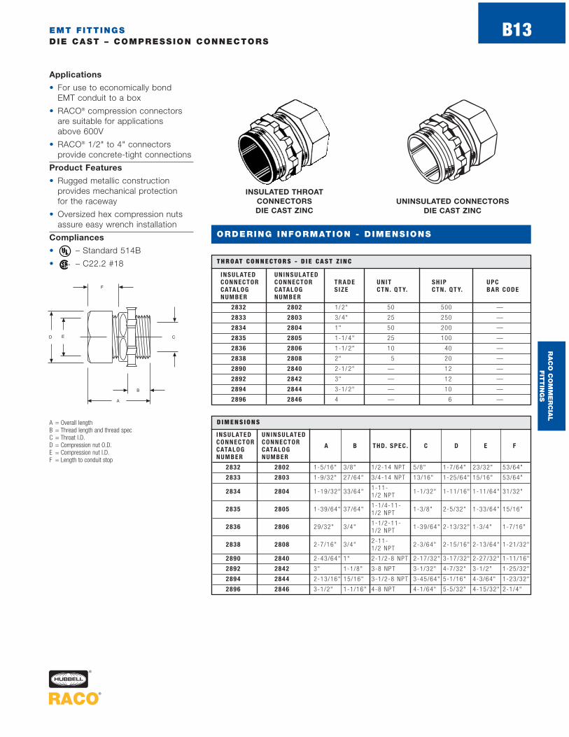
EMT FITTINGSDIE CAST – COMPRESSION CONNECTORS
B13
ORDERING INFORMATION - DIMENSIONS
Applications
• For use to economically bond EMT conduit to a box
• RACO® compression connectorsare suitable for applications above 600V
• RACO® 1/2" to 4" connectors provide concrete-tight connections
Product Features
• Rugged metallic construction provides mechanical protection for the raceway
• Oversized hex compression nutsassure easy wrench installation
Compliances
• – Standard 514B
• – C22.2 #18®
®
INSULATED THROATCONNECTORSDIE CAST ZINC
A = Overall lengthB = Thread length and thread specC = Throat I.D.D = Compression nut O.D.E = Compression nut I.D.F = Length to conduit stop
INSULATED UNINSULATEDCONNECTOR CONNECTORCATALOG CATALOG A B THD. SPEC . C D E F
NUMBER NUMBER
2832 2802 1-5/16" 3/8" 1/2-14 NPT 5/8" 1-7/64" 23/32" 53/64"
2833 2803 1-9/32" 27/64" 3/4-14 NPT 13/16" 1-25/64" 15/16" 53/64"
2834 2804 1-19/32" 33/64"1-11-
1-1/32" 1-11/16" 1-11/64" 31/32"1/2 NPT
2835 2805 1-39/64" 37/64"1-1/4-11-
1-3/8" 2-5/32" 1-33/64" 15/16"1/2 NPT
2836 2806 29/32" 3/4"1-1/2-11-
1-39/64" 2-13/32" 1-3/4" 1-7/16"1/2 NPT
2838 2808 2-7/16" 3/4"2-11-
2-3/64" 2-15/16" 2-13/64" 1-21/32"1/2 NPT
2890 2840 2-43/64" 1" 2-1/2-8 NPT 2-17/32" 3-17/32" 2-27/32" 1-11/16"
2892 2842 3" 1-1/8" 3-8 NPT 3-1/32" 4-7/32" 3-1/2" 1-25/32"
2894 2844 2-13/16" 15/16" 3-1/2-8 NPT 3-45/64" 5-1/16" 4-3/64" 1-23/32"
2896 2846 3-1/2" 1-1/16" 4-8 NPT 4-1/64" 5-5/32" 4-15/32" 2-1/4"
D I M E N S I O N S
INSULATED UNINSULATEDCONNECTOR CONNECTOR TRADE UNIT SH IP UPCCATALOG CATALOG S IZE CTN . QTY. CTN . QTY. BAR CODENUMBER NUMBER
2832 2802 1/ 2" 50 500 —
2833 2803 3/ 4" 25 250 —
2834 2804 1" 50 200 —
2835 2805 1-1/ 4" 25 100 —
2836 2806 1-1/ 2" 10 40 —
2838 2808 2" 5 20 —
2890 2840 2-1/ 2" — 12 —
2892 2842 3" — 12 —
2894 2844 3-1/ 2" — 10 —
2896 2846 4 — 6 —
T H R O AT C O N N E C T O R S - D I E C A S T Z I N C
UNINSULATED CONNECTORS DIE CAST ZINC
RA
CO
CO
MM
ER
CIA
L
FIT
TIN
GS

EMT FITTINGSDIE CAST – COMPRESSION COUPLINGS
ORDERING INFORMATION - DIMENSIONS
Applications
• For use to economically couple two ends of EMT conduit
• RACO® compression couplings are suitable for applications above 600V
• RACO® 1/2" to 4" couplings provide concrete-tight connections
Product Features
• Rugged metallic construction provides mechanical protection for the raceway
• Hex compression nuts assure easy wrench installation
Compliances
• – Standard 514B
• – C22.2 #18®
®
COUPLINGS DIE CAST ZINC
CATALOG UNIT SH IP UPCNUMBER TRADE S IZE CTN . QTY. CTN . QTY. BAR CODE
2822 1/ 2" 50 500 —
2823 3/ 4" 25 250 —
2824 1" 50 200 —
2825 1-1/ 4" 25 100 —
2826 1-1/ 2" 10 40 —
2828 2" 5 20 —
2870 2-1/ 2" — 12 —
2872 3" — 12 —
2874 3-1/ 2" — 10 —
2876 4" — 6 —
C O U P L I N G S - D I E C A S T Z I N C
A = Overall lengthB = Compression nut O.D.C = Compression nut I.D.D = Length to center stop CATALOG
NUMBER A B C D
2822 1-45/64" 1-7/64" 23/32" 27/32"
2823 1-45/64" 1-13/32" 59/64" 13/16"
2824 1-31/32" 1-11/16" 1-3/16" 31/32"
2825 2" 2-11/64" 1-17/32" 31/32"
2826 3-1/16" 2-13/32" 1-3/4" 1- 1 /2"
2828 3-3/32" 2-13/16" 2-3/16" 1-17/32"
2870 3-9/16" 3-17/32" 2-7/8" 1-45/64"
2872 3-9/16" 4-3/16" 3-17/32" 1- 3 /4"
2874 3-13/16" 4-3/4" 4-1/16" 1-27/32"
2876 3-27/32" 5-5/16" 4-1/2" 1-7/8"
D I M E N S I O N S
RA
CO
CO
MM
ER
CIA
L
FIT
TIN
GS
B14

EMT FITTINGSDIE CAST – COMPRESSION OFFSET CONNECTORS
ORDERING INFORMATION - DIMENSIONS
Applications
• For use to economically bond EMT conduit to a box
• RACO® compression offset connectors are suitable for applications above 600V
Product Features
• Rugged metallic construction provides mechanical protection for the raceway
• Hex compression nuts assure easy wrench installation
Compliances
• – Standard 514B
• – C22.2 #18®
®
OFFSET CONNECTORSDIE CAST ZINC
CATALOG UNIT SH IP UPCNUMBER TRADE S IZE CTN . QTY. CTN . QTY. BAR CODE
1952 1/ 2" — 50 —
1953 3/ 4" — 25 —
O F F S E T C O N N E C T O R S - D I E C A S T Z I N C
A = Overall lengthB = Compression nut O.D.C = Compression nut I.D.D = Thread length and thread specE = Amount of offsetF = Throat I.D.
CATALOGNUMBER A B C D E F THD. SPEC .
1952 2-5/32" 1-3/32" 23/32" 3/8" 3/8" 5/8" 1/2-14 NPS
1953 2-57/64" 1-5/16" 61/64" 7/16" 3/4" 13/16" 3/4-14 NPS
D I M E N S I O N S
RA
CO
CO
MM
ER
CIA
L
FIT
TIN
GS
B15

CATALOGNUMBER A B C D E
1352 1-5/32" 3/4" 1-11/32" 1-1/8" 23/32"
1353 1-7/16" 31/32" 1-17/32" 1-3/8" 15/16"
1354 1-21/32" 1-7/32" 1-5/8" 1-43/64" 1-11/64"
D I M E N S I O N S
EMT FITTINGSDIE CAST/STEEL – TWO-PIECE CONNECTORS AND COMBINATION COUPLINGS
ORDERING INFORMATION - DIMENSIONS
Die Cast Two-Piece ConnectorsApplications
• For use in dry locations to economically bond EMT conduit to a box or enclosure
• RACO® 1/2" and 3/4" two-piececonnectors provide concrete-tightconnections
Die Cast Two-Piece ConnectorsProduct Feature
• Rugged metallic constructioninsures mechanical protection
Die Cast Two-Piece ConnectorsCompliance
• – Standard 514B
Steel Combination CouplingsApplication
• Use RACO® Cat. Nos. 1352-1354when coupling threaded rigid/IMCconduit to EMT
Steel Combination CouplingsProduct Features
• Rugged metallic constructioninsures mechanical protection
• All steel components are zinc elec-tro plated for corrosion protection
Steel Combination CouplingsCompliance
• – Standard 514B®
®
EMT – RIGID COUPLINGS THREADED/COMPRESSION
STEELTWO-PIECE CONNECTORS
DIE CAST ZINC
CATALOG UNIT SH IP UPCNUMBER TRADE S IZE CTN . QTY. CTN . QTY. BAR CODE
2702 1/ 2" — 100 —
2703 3/ 4" — 50 —
T W O - P I E C E C O N N E C T O R S - D I E C A S T Z I N C
CATALOG UNIT SH IP UPCNUMBER TRADE S IZE CTN . QTY. CTN . QTY. BAR CODE
1352 1/2" — 25 —
1353 3/4" — 25 —
1354 1" — 25 —
E M T – R I G I D C O U P L I N G S T H R E A D E D / C O M P R E S S I O N - S T E E L
A = Overall lengthB = O.D. of nutC = O.D. of bodyD = I.D. of throat
A = O.D. of hubB = Throat I.D.C = Overall lengthD = Nut O.D.E = Nut I.D.
CATALOGNUMBER A B C D
2702 11/16" 1-3/64" 15/16" 39/64"
2703 13/16" 1-5/16" 1-5/32" 13/16"
D I M E N S I O N S
RA
CO
CO
MM
ER
CIA
L
FIT
TIN
GS
B16

EMT FITTINGSSTEEL COMBINATION COUPLINGS
ORDERING INFORMATION - DIMENSIONS
Application
• Use RACO® Cat. Nos. 1432-1434when coupling unthreaded rigid/IMC to EMT
Product Features
• Rugged metallic constructioninsures mechanical protection
• All steel components are zinc electro plated for corrosion protection
• UPC bar coded fittings are individually polybagged with a preprinted UPC-A bar code and packaged in pre-scored tear top cartons for an attractive presentation
EMT – RIGID COUPLINGS SET SCREW STEEL
CATALOG UNIT SH IP UPCNUMBER TRADE S IZE CTN . QTY. CTN . QTY. BAR CODE
1432 1/2" — 25 —
1432-8 1/2" 1 25
1433 3/4" — 25 —
1433-8 3/4" 1 15
1434 1" — 25 —
1434-8 1" 1 15
E M T – R I G I D C O U P L I N G S S E T S C R E W - S T E E L
A = Overall lengthB = O.D. rigid sideC = I.D. rigid sideD = O.D. EMT side
E = I.D. EMT sideF = Length to stopG = Screw spec
CATALOGNUMBER A B C D E F G
1432 2-5/16" 1" 7/8" 7/8" 23/32" 25/32" 1/4-28 x 3 /8" Pan Head
1432-8 2-5/16" 1" 7/8" 7/8" 23/32" 25/32" 1/4-28 x 3 /8" Pan Head
1433 2-5/8" 1-1/4" 1-5/64" 1-7/64" 15/16" 27/32" 1/4-28 x 3 /8" Pan Head
1433-8 2-5/8" 1-1/4" 1-5/64" 1-7/64" 15/16" 27/32" 1/4-28 x 3 /8" Pan Head
1434 3-5/32" 1-1/2" 1-11/32" 1-11/32" 1-3/16" 1-1/16" 1/4-28 x 3 /8" Pan Head
1434-8 3-5/32" 1-1/2" 1-11/32" 1-11/32" 1-3/16" 1-1/16" 1/4-28 x 3 /8" Pan Head
D I M E N S I O N S
RA
CO
CO
MM
ER
CIA
L
FIT
TIN
GS
B17

EMT FITTINGSMALLEABLE IRON/DIE CAST – COMBINATION COUPLINGS
Application
• Use RACO® Cat. Nos. 1941-1943 or Cat. Nos. 1482-1484 when coupling flexible metal conduit to EMT
Product Features
• Rugged metallic constructioninsures mechanical protection
• All steel/malleable components are zinc electro plated for corrosion protection
• UPC bar coded fittings are individually polybagged with a preprinted UPC-A bar code and packaged in pre-scored tear top cartons for an attractive presentation
Compliances
• – Standard 514B
• – Certified®
EMT – FLEX COUPLINGSSQUEEZE/COMPRESSION
MALLEABLE IRON
EMT-FLEX COUPLINGS SCREW-IN/COMPRESSION
DIE CAST ZINC
CATALOG FLEX EMT UNIT SH IP UPCNUMBER S IZE S IZE CTN . QTY. CTN . QTY. BAR CODE
1941* 3/8" 1/2" — 25 —
1942 1/2" 1/2" — 25 —
1942-8 1/2" 1/2" 1 25
1943 3/4" 3/4" — 25 —
1943-8 3/4" 3/4" 1 20
E M T – F L E X C O U P L I N G S S Q U E E Z E / C O M P R E S S I O N - M A L L E A B L E I R O N
CATALOG FLEX EMT UNIT SH IP UPCNUMBER S IZE S IZE CTN . QTY. CTN . QTY. BAR CODE
1482 1/2" 1/2" 50 500 —
1483 3/ 4" 3/ 4" 25 250 —
1484 1" 1" 25 250 —
E M T- F L E X C O U P L I N G S S C R E W - I N / C O M P R E S S I O N - D I E C A S T Z I N C
A = Width across flex sideB = Overall lengthC = Nut O.D.D = Nut I.D.E = Clamping range (flex side)
CATALOGNUMBER A B
1482 .84" 1 .10"
1483 .95" 1 .30"
1484 1.11" 1.62"
D I M E N S I O N S
CATALOGNUMBER A B C D E
1941 1 -1 /4 " 1 -5 /1 6 " 1 -7 /6 4 " 2 3 /3 2 " 17 /32 -5 /8 "
1942 1 -1 /2 " 1 -3 /4 " 1 -7 /6 4 " 2 3 /3 2 " 13 /16 -15 /16"
1942 -8 1 -1 /2 " 1 -3 /4 " 1 -7 /6 4 " 2 3 /3 2 " 13 /16 -15 /16"
1943 1 -3 /4 " 1 -5 3 /6 4 " 1 -3 /8 " 1 5 /1 6 " 1 -1 /32 -1 -1 /8 "
1943-8 1 -3 /4 " 1 -5 3 /6 4 " 1 -3 /8 " 1 5 /1 6 " 1 -1 /32 -1 -1 /8 "
D I M E N S I O N S
ORDERING INFORMATION - DIMENSIONS
RA
CO
CO
MM
ER
CIA
L
FIT
TIN
GS
B18
*No t U . L . L i s t ed

EMT FITTINGSMALLEABLE IRON – CLAMPBACKS
ORDERING INFORMATION - DIMENSIONS
Applications
• For use with RACO® straps to permit space between the conduitand the mounting surface
• Use of clamp backs in outdoorlocations can prevent the buildupof snow and rain between the conduit and the mounting surface
Product Features
• All malleable construction insures durability and mechanicalprotection
• Zinc electro plated for added corrosion protection
• Elongated bolt holes make alignment with straps easy
• For use in mounting EMT conduitin wet or dry locations
CLAMP BACKS MALLEABLE IRON
CATALOG RIG ID/ IMC EMT UNIT SH IP UPCNUMBER S IZE S IZE CT N . QT Y. CT N . QT Y. BAR CODE
1342 1/2" 3/4" — 100 —
1343 3/ 4" 1" — 100 —
1344 1" 1-1/4" — 50 —
1345 1-1/4" 1-1/2" — 25 —
1346 1-1/2" 2" — 25 —
1348 2" 2" — 10 —
1347 2-1/2" 2-1/2" — 10 —
1349 3" 3" — 10 —
1350 3-1/2" 3-1/2" — 5 —
1351 4" 4" — 5 —
C L A M P B A C K S - M A L L E A B L E I R O N
A = Overall lengthB = WidthC = Hole diameterD = Slot sizeE = Height
CATALOGNUMBER A B C D E
1342 2-5/16" 1" 13/32" 3/8 x 9 /16" 7/16"
1343 2-3/8" 1-1/32" 13/32" 7/16 x 9 /16" 7/16"
1344 3" 1-1/4" 3/8" 15/32 x 19/32" 9/16"
1345 3-5/8" 1-15/32" 15/32" 1/2 x 3 /4" 11/16"
1346 3-29/32" 1-9/16" 7/16" 7/16 x 25/32" 1/2"
1348 4-3/4" 1-15/16" 9/16" 5/8 x 29/32" 31/32"
1347 5-7/8" 2-3/8" 1/2" 3/4 x 1" 7/8"
1349 6-3/4" 2-9/16" 1/2" 3/4 x 1" 7/8"
1350 7-5/16" 2-13/16" 1/2" 3/4 x 1" 1"
1351 8-9/32" 2-15/16" 1/2" 3/4 x 1" 1"
D I M E N S I O N S
RA
CO
CO
MM
ER
CIA
L
FIT
TIN
GS
B19
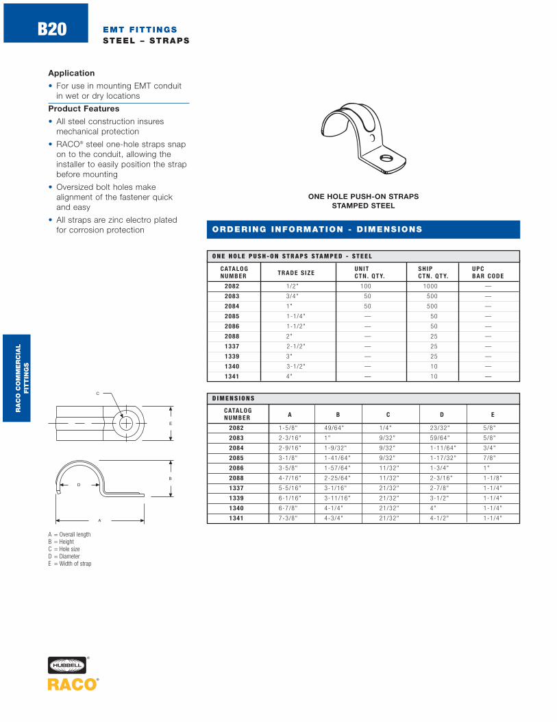
EMT FITTINGSSTEEL – STRAPS
ORDERING INFORMATION - DIMENSIONS
Application
• For use in mounting EMT conduitin wet or dry locations
Product Features
• All steel construction insuresmechanical protection
• RACO® steel one-hole straps snapon to the conduit, allowing theinstaller to easily position the strapbefore mounting
• Oversized bolt holes make alignment of the fastener quick and easy
• All straps are zinc electro platedfor corrosion protection
ONE HOLE PUSH-ON STRAPS STAMPED STEEL
CATALOG UNIT SH IP UPCNUMBER TRADE S IZE CTN . QTY. CTN . QTY. BAR CODE
2082 1/2" 100 1000 —
2083 3/4" 50 500 —
2084 1" 50 500 —
2085 1-1/4" — 50 —
2086 1-1/2" — 50 —
2088 2" — 25 —
1337 2-1/2" — 25 —
1339 3" — 25 —
1340 3-1/2" — 10 —
1341 4" — 10 —
O N E H O L E P U S H - O N S T R A P S S TA M P E D - S T E E L
A = Overall lengthB = HeightC = Hole sizeD = DiameterE = Width of strap
CATALOGNUMBER A B C D E
2082 1-5/8" 49/64" 1/4" 23/32" 5/8"
2083 2-3/16" 1" 9/32" 59/64" 5/8"
2084 2-9/16" 1-9/32" 9/32" 1-11/64" 3/4"
2085 3-1/8" 1-41/64" 9/32" 1-17/32" 7/8"
2086 3-5/8" 1-57/64" 11/32" 1-3/4" 1"
2088 4-7/16" 2-25/64" 11/32" 2-3/16" 1-1/8"
1337 5-5/16" 3-1/16" 21/32" 2-7/8" 1-1/4"
1339 6-1/16" 3-11/16" 21/32" 3-1/2" 1-1/4"
1340 6-7/8" 4-1/4" 21/32" 4" 1-1/4"
1341 7-3/8" 4-3/4" 21/32" 4-1/2" 1-1/4"
D I M E N S I O N S
RA
CO
CO
MM
ER
CIA
L
FIT
TIN
GS
B20

EMT FITTINGSSTEEL – STRAPS
ORDERING INFORMATION - DIMENSIONS
Application
• For use in mounting EMT conduitin wet or dry locations
Product Features
• All steel construction insuresmechanical protection
• Oversized bolt holes make alignment of the fastener(s) quick and easy
• All straps are zinc electro platedfor corrosion protection
TWO HOLE STRAPS STAMPED STEEL
CATALOG UNIT SH IP UPCNUMBER TRADE S IZE CTN . QTY. CTN . QTY. BAR CODE
2092 1/2" — 100 —
2093 3/4" — 100 —
2094 1" — 100 —
2095 1-1/4" — 50 —
2096 1-1/2" — 50 —
2098 2" — 25 —
2239 2-1/2" — 25 —
2240 3" — 25 —
2241 3-1/2" — 25 —
2242 4" — 10 —
T W O H O L E S T R A P S S TA M P E D - S T E E L
CATALOGNUMBER A B C D E F G
2092 .625" 2.140" 1.625" .706" .750" .032" x .625" .187"
2093 .625" 2.288" 1.715" .922" 1.015" .032" x .625" .187"
2094 .750" 2.750" 2.140" 1.163" 1.235" .036" x .750" .250"
2095 .750" 3.520" 2.750" 1.510" 1.540" .036" x .750" .250"
2096 .750" 3.770" 3.141" 1.740" 1.785" .036" x .750" .250"
2098 .750" 4.453" 3.812" 2.147" 2.270" .036" x .750" .250"
2239 1.000" 5.720" 4.680" 2.875" 3.050" .059" x 1 .000" .312"
2240 1.000" 6.578" 5.515" 3.500" 3.670" .059" x 1 .000" .312"
2241 1.000" 7.156" 6.125" 4.000" 3.975" .059" x 1 .000" .312"
2242 1.000" 7.718" 6.718" 4.500" 4.700" .059" x 1 .000" .312"
D I M E N S I O N S
RA
CO
CO
MM
ER
CIA
L
FIT
TIN
GS
B21

EMT FITTINGSMALLEABLE AND STEEL – STRAPS
ORDERING INFORMATION - DIMENSIONS
ONE HOLE STRAPS MALLEABLE IRON
CATALOG UNIT SH IP UPCNUMBER TRADE S IZE CTN . QTY. CTN . QTY. BAR CODE
1310 2-1/2" — 10 —
1312 3" — 10 —
1314 3-1/2" — 5 —
1316 4" — 5 —
O N E H O L E S T R A P S - M A L L E A B L E I R O N
Malleable-Straps Application
• For use in mounting EMT conduitin wet or dry locations
Steel – Straps Application
• For use in mounting EMT conduit
Malleable – Straps Product Features
• All malleable construction insuresmechanical protection
• Oversized bolt holes make alignment of the fastener quickand easy
• All straps are zinc electro platedfor corrosion protection
Steel-Straps Product Feature
• Stamped steel straps are pregalvanized for added corrosion protection
Steel-Straps Compliance
• – (2252-2253)
A = Overall lengthB = HeightC = Hole sizeD = DiameterE = Width of strap
CATALOGNUMBER A B C D E
1310 6-7/16" 3-9/32" 21/32" 2-7/8" 1-13/16"
1312 7-1/2" 4" 21/32" 3-1/2" 2"
1314 8-1/8" 4-1/2" 53/64" 4" 2-1/8"
1316 8-7/8" 5-5/16" 3/4" 4-1/2" 2-1/4"
D I M E N S I O N S
NAIL-UP STRAPS STAMPED STEEL
A = Width of strapB = Height of strap
CATALOG UNIT SH IP UPCNUMBER TRADE S IZE CTN . QTY. CTN . QTY. BAR CODE
2252 1/2" 100 1000 —
2253 3/4" 100 1000 —
2254 1" 100 1000 —
N A I L - U P S T R A P S S TA M P E D - S T E E L
CATALOGNUMBER A B
2252 1-1/16" 2-3/16"
2253 1-1/4" 2-19/64"
2254 1-1/2" 2-13/32"
D I M E N S I O N S
RA
CO
CO
MM
ER
CIA
L
FIT
TIN
GS
B22

UNINSULATED INSULATED UNIT SH IP UPCCONNECTOR CONNECTOR TRADE CTN . CTN . BARCATALOG CATALOG S IZE QTY. QTY. CODENUMBER NUMBER
3002 — 1/2" 25 100 —
3003 — 3/4" 25 100 —
3004 — 1" — 10 —
3005 — 1-1/4" — 5 —
3006 — 1-1/2" — 5 —
3008 — 2" — 5 —
2140 2160 2-1/2" — 5 —
2142 2162 3" — 1 —
2144 2164 3-1/2" — 1 —
2146 2166 4" — 1 —
RIGID AND IMC FITTINGSSTEEL – SET SCREW CONNECTORS
UNINSULATED CONNECTORS STEEL
S E T S C R E W C O N N E C T O R S - S T E E L
Applications
• For use in dry locations to bond unthreaded rigid/IMC conduit to a box or enclosure
• RACO® steel set screw connectorsare suitable for concrete-tightapplications when taped
Production Features
• All steel construction insuresmechanical protection for the raceway
• 2-1/2" to 4" trade sizes are also UL Listed for use on EMTconduit, allowing for design and installation flexibility
• All components are zinc electroplated for corrosion protection
Compliance
• – Standard 514B®
INSULATED UNINSULATEDCONNECTOR CONNECTOR A B THD. SPEC . C D E F GCATA L O G N U MB E R CATALOG NUMBER SET SCREW
3002 — 1- 11 /64" 1 3 /3 2 " 1 /2 -1 4 NP S 3 9 /6 4 " 2 3 /3 2 "Hex head s c r ew
1 -1 1 /64" 55 /64"1 /4 -2 0 x 1 /4 "
3003 — 1- 13 /64" 1 3 /3 2 " 3 /4 -1 4 NP S 5 3 /6 4 " 2 3 /3 2 "Hex head s c r ew
1 -1 3 /32" 1 -5 /64"1 /4 -2 0 x 1 /4 "
3004 — 1- 1 /2 " 1 /2 " 1 -1 1 -1 /2 NP S 1 -3 /6 4 " 2 9 /3 2 "Hex head s c r ew
1 -1 1 /16" 1 -11 /32"1 /4 -2 0 x 1 /4 "
3005 — 1- 11 /16" 1 /2 " 1 -1 /4 -1 1 -1 /2 NP S 1 -2 5 /6 4 " 1 -5 /6 4 "Hex head s c r ew
2 -1 /8 " 1 -11 /16"5 /1 6 -2 4 x 5 /1 6 "
3006 — 1- 29 /32" 1 7 /3 2 " 1 -1 /2 -1 1 -1 /2 NP S 1 -3 9 /6 4 " 1 -1 /4 "Hex head s c r ew
2 -3 /8 " 2 -15 /16"5 /1 6 -2 4 x 5 /1 6 "
3008 — 2" 39 /64" 2 -11 -1 /2 NPS 2-3 /32" 1 -9 /32"Hex head s c r ew
2 -7 /8 " 2 -7 /16"5 /1 6 -2 4 x 5 /1 6 "
D I M E N S I O N S
ORDERING INFORMATION - DIMENSIONS
INSULATED THROATCONNECTORS
STEEL
A = Overall lengthB = Thread length
and thread specC = Throat I.D.D = Length to conduit stop
E = Screw spec (type of head, length,thread spec)
F = Body O.D.G = Body I.D.
RA
CO
CO
MM
ER
CIA
L
FIT
TIN
GS
B23

RIGID AND IMC FITTINGSSTEEL – SET SCREW COUPLINGS
ORDERING INFORMATION - DIMENSIONS
Applications
• For use in dry locations to coupletwo ends of unthreaded rigid/IMC conduit
• RACO® steel set screw couplingsare suitable for concrete-tightapplications when taped
Production Features
• All steel construction insuresmechanical protection for the raceway
• 2-1/2" to 4" trade sizes are also UL Listed for use on EMTconduit, allowing for design and installation flexibility
• All components are zinc electroplated for corrosion protection
Compliance
• – Standard 514B®
COUPLINGS STEEL
CATALOG UNIT SH IP UPCNUMBER TRADE S IZE CTN . QTY. CTN . QTY. BAR CODE
3022 1/2" — 25 —
3023 3/4" — 10 —
3024 1" — 5 —
3025 1-1/4" — 5 —
3026 1-1/2" — 5 —
3028 2" — 5 —
2150 2-1/2" — 5 —
2152 3" — 1 —
2154 3-1/2" — 1 —
2156 4" — 1 —
C O U P L I N G S - S T E E L
A = Overall lengthB = O.D. of bodyC = I.D. of bodyD = Length to center stopE = Screw spec (type of head, length, thread spec)
CATALOG ENUMBER A B C D THD. SPEC .
3022 1-1/2" 1-11/64" 55/64" 23/32"Hex head sc rew1/4 -20 x 1 /4"
3023 1-1/2" 1-13/32" 1-5/64" 23/32"Hex head sc rew1/4-20 x 1 /4"
3024 1-7/8" 1-11/16" 1-11/32" 29/32"Hex head sc rew1/4-20 x 1 /4"
3025 2-3/16" 2-1/8" 1-11/16" 1-5/64"Hex head sc rew5/16-24 x 5 /16"
3026 2-19/32" 2-3/8" 1-15/16" 1-1/4"Hex head sc rew5/16-24 x 5 /16"
3028 2-11/16" 2-7/8" 2-7/16" 1-9/32"Hex head sc rew5/16-24 x 5 /16"
D I M E N S I O N S
RA
CO
CO
MM
ER
CIA
L
FIT
TIN
GS
B24

RIGID AND IMC FITTINGSSTEEL/MALLEABLE IRON – COMPRESSION CONNECTORS
ORDERING INFORMATION - DIMENSIONS
Applications
• For use to bond unthreadedrigid/IMC conduit to a box or enclosure
• RACO® 1/2" to 4" connectors and couplings provide concrete-tight connectors
Product Features
• All steel/malleable constructioninsures mechanical protection for the raceway
• Hex compression nuts assure easy wrench installation
• All components are zinc electroplated for corrosion protection
Compliances
• – Standard 514B
• – C22.2 #18 (1802-1806)®
®
UNINSULATED CONNECTORS STEEL/MALLEABLE IRON
CATALOG UNIT SH IP UPCNUMBER TRADE S IZE CTN . QTY. CTN . QTY. BAR CODE
1802 1/ 2" 25 100 —
1803 3/ 4" 25 100 —
1804 1" 10 50 —
1805 1-1/ 4" 5 25 —
1806 1-1/ 2" — 5 —
1808 2" — 5 —
1810 2-1/ 2" — 5 —
1812 3" — 1 —
1814 3-1/ 2" — 1 —
1816 4" — 1 —
U N I N S U L AT E D C O N N E C T O R S - S T E E L / M A L L E A B L E I R O N
CATALOGNUMBER A B THD. SPEC . C D E F
1802 1-3/8" 33/64" 1/2-14 NPS 39/64" 15/32" 55/64" 27/32"
1803 1-7/16" 35/64" 3/4-14 NPS 53/64" 1-7/16" 1-5/64" 29/32"
1804 1-11/16" 5/8" 1-11-1/2 NPS 1-1/16" 1-3/4" 1-11/32" 31/32"
1805 1-13/16" 21/32" 1-1/4-11-1/2 NPS 1-25/64" 2-5/32" 1-45/64" 1-1/8"
1806 2-1/16" 23/32" 1-1/2-11-1/2 NPS 1-5/8" 2-3/8" 1-15/16" 1-1/4"
1808 2-3/8" 21/32" 2-11-1/2 NPS 2-1/16" 3-1/16" 2-13/32" 1-1/2"
1810 3-7/8" 15/16" 2-1/2-8 NPS 2-9/16" 3-15/16" 2-29/32" 2-13/16"
1812 4" 1" 3-8 NPS 3-5/32" 4-21/32" 3-35/64" 2-7/8"
1814 4-5/16" 1" 3-1/2-8 NPS 3-21/32" 5-13/64" 4-3/64" 3-1/8"
1816 4-1/2" 1" 4-8 NPS 4-1/8" 5-3/4" 4-9/16" 3-3/8"
D I M E N S I O N S
RA
CO
CO
MM
ER
CIA
L
FIT
TIN
GS
B25
A = Overall lengthB = Thread length and thread specC = Throat I.D.D = Compression nut O.D.E = Compression nut I.D.F = Length to conduit stop

RIGID AND IMC FITTINGSSTEEL/MALLEABLE IRON – COMPRESSION COUPLINGS
ORDERING INFORMATION - DIMENSIONS
Applications
• For use to couple two ends of conduit
• RACO® 1/2" to 4" couplings provide concrete-tight connectors
Product Features
• All steel/malleable constructioninsures mechanical protection for the raceway
• Hex compression nuts assure easy wrench installation
• All components are zinc electroplated for corrosion protection
Compliances
• – Standard 514B
• – C22.2 #18 (1822-1826)®
®
COUPLINGS STEEL/MALLEABLE IRON
CATALOG UNIT SH IP UPCNUMBER TRADE S IZE CTN . QTY. CTN . QTY. BAR CODE
1822 1/2" 25 100 —
1823 3/4" 10 50 —
1824 1" 5 25 —
1825 1-1/4" 5 25 —
1826 1-1/2" — 5 —
1828 2" — 5 —
1830 2-1/2" — 5 —
1832 3" — 1 —
1834 3-1/2" — 1 —
1836 4" — 1 —
C O U P L I N G S - S T E E L / M A L L E A B L E I R O N
A = Overall lengthB = Compression nut O.D.C = Compression nut I.D.D = Length to center stop
CATALOGNUMBER A B C D
1822 1-3/4" 1-5/32" 55/64" 27/32"
1823 1-15/16" 1-7/16" 1-5/64" 29/32"
1824 2-1/16" 1-3/4" 1-11/32" 31/32"
1825 2-7/16" 2-5/32" 1-45/64" 1-1/8"
1826 2-19/32" 2-3/8" 1-15/16" 1-1/4"
1828 3-7/32" 3-1/16" 2-13/32" 1-1/2"
1830 5-3/4" 3-15/16" 2-29/32" 2-1/2"
1832 5-23/32" 4-21/32" 3-35/64" 2-1/2"
1834 6-1/2" 5-13/64" 4-3/64" 3-3/16"
1836 6-13/16" 5-3/4" 4-9/16" 3-3/32"
D I M E N S I O N S
RA
CO
CO
MM
ER
CIA
L
FIT
TIN
GS
B26

RIGID AND IMC FITTINGSMALLEABLE - SHORT ELBOWS
ORDERING INFORMATION - DIMENSIONS
Applications
• For use with threaded rigid/IMC conduit
• 90 degree short elbows are idealfor use in tight locations wherebending of conduit is not practical
Product Features
• All malleable construction insures mechanical protection for the raceway
• All components are zinc electroplated for corrosion protection
Compliance
• – Standard 514B®
90 DEGREE SHORT ELBOWSMALLEABLE IRON
CATALOG UNIT SH IP UPCNUMBER TRADE S IZE CTN . QTY. CTN . QTY. BAR CODE
1722 1/2" — 50 —
1723 3/4" — 25 —
1724* 1" — 10 —
9 0 D E G R E E S H O R T E L B O W S - M A L L E A B L E I R O N
A = Hub O.D.B = Hub I.D.C = Length to end of hubD = Length to end of threadE = Thread lengthF = Throat I.D.G = Thread spec
CATALOG GNUMBER A B C D E F T HREAD SPEC
1722 1-5/64" 3/4" 1-1/16" 1-17/32" 1/2" 39/64" 1/2-14 NPS
1723 1-9/32" 61/64" 1-9/32" 1-15/32" 9/16" 13/16" 3/4-14 NPS
1724 1-47/64" 1-7/32" 1-21/32" 1-9/16" 1/2" 1-1/16" 1-11-1/2 NPS
D I M E N S I O N S
* No t UL L i s ted
RA
CO
CO
MM
ER
CIA
L
FIT
TIN
GS
B27

CATALOG CNUMBER A B THD. SPEC . D E F
2662 1-5/32" 49/64" 1/2-14 NPT 1-7/8" 3/8" 5/8"
2663 1-11/32" 31/32" 3/4-14 NPT 2-3/16" 7/16" 13/16"
2664RAC 1-5/8" 1-7/32" 1-11/2 NPT 3-1/8" 9/16" 1-7/32"
RIGID AND IMC FITTINGSDIE CAST – HANDY ELLS
ORDERING INFORMATION - DIMENSIONS
Applications
• For use with threaded rigid/IMCconduit to bond conduit to a boxor enclosure, or to couple twoends of rigid/IMC conduit
• Use handy ells when bending conduit is not practical
Product Feature
• Gasket and cover included
Compliance
• – Standard 514B
• – C22.2 #18 (2652-2653)®
®
90 DEGREE HANDY ELLS THREADED CONNECTORS
DIE CAST ZINC
90 DEGREE HANDY ELLS THREADED COUPLINGS
DIE CAST ZINC
CATALOG UNIT SH IP UPCNUMBER TRADE S IZE CTN . QTY. CTN . QTY. BAR CODE
2662 1/2" 10 100 —
2663 3/4" 5 50 —
2664RAC 1” — 25 —
9 0 D E G R E E H A N DY - E L L S T H R E A D E D C O N N E C T O R S - D I E C A S T Z I N C
CATALOGNUMBER A B C D
2652 1-1/8" 49/64" 1/2-14 NPS 1-7/8"
2653 1-11/32" 31/32" 3/4-14 NPS 2-1/4"
2654 1-5/8" 1-7/32" 1-11/2 NPS 3-1/8"
2655 2" 1-9/16" 1-1/4-11-1/2 NPS 3-1/4"
D I M E N S I O N S
A = Width of bodyB = Throat I.D.C = Thread specD = Overall lengthE = Thread lengthF = Throat I.D.
A = Width of bodyB = Throat I.D.C = Thread specD = Overall length
CATALOG UNIT SH IP UPCNUMBER TRADE S IZE CTN . QTY. CTN . QTY. BAR CODE
2652 1/2" 10 100 —
2653 3/4" 5 50 —
2654 1" — 25 —
2655 1-1/4" — 20 —
9 0 D E G R E E H A N DY - E L L S T H R E A D E D C O U P L I N G S - D I E C A S T Z I N C
D I M E N S I O N S
RA
CO
CO
MM
ER
CIA
L
FIT
TIN
GS
B28

CATALOG UNIT SH IP UPCNUMBER TRADE S IZE CTN . QTY. CTN . QTY. BAR CODE
1468 2" 5 25 —
1470 2-1/2" 2 10 —
1472 3" 2 10 —
1474 3-1/2" 1 5 —
1476 4" 1 5 —
1477 5" — 2 —
1478 6" — 1 —
H I N G E D C O U P L I N G S - M A L L E A B L E I R O N
RIGID AND IMC FITTINGSMALLEABLE IRON – HINGED COUPLINGS
ORDERING INFORMATION - DIMENSIONS
Applications
• For use on threaded rigid/IMC conduit
• Ideal for coupling runs of conduitthat are closely spaced, where conduit is tight against a wall, orwhere conduit cannot be turned
• RACO® hinged couplings provideconcrete-tight connections
Product Features
• All malleable construction insures mechanical protection of the raceway
• Unique tongue-in-groove designspeeds installation
• All components are zinc electro plated for corrosion protection
Compliance
• – Standard 514B®
HINGED COUPLINGSMALLEABLE IRON
A = WidthB = Diameter*C = Length
CATALOGNUMBER A B C
1468 2" 2-5/8" 3-7/8"
1470 3-1/16" 3-1/8" 4-3/4"
1472 3-3/16" 3-7/8" 5-7/16"
1474 3-5/16" 3-3/8" 5-15/16"
1476 3-3/8" 3-15/16" 6-11/16"
1477 3-1/2" 5" 7-15/16"
1478 4" 6-1/8" 9-7/16"
D I M E N S I O N S
RA
CO
CO
MM
ER
CIA
L
FIT
TIN
GS
B29

RIGID AND IMC FITTINGSSTEEL/MALLEABLE IRON – THREE-PIECE COUPLINGS
ORDERING INFORMATION - DIMENSIONS
Applications
• For use with threaded rigid/IMC conduit
• Use three-piece couplings to couple conduit ends when the conduit cannot be turned
• RACO® three-piece couplings provide concrete-tight connections
Product Features
• All steel/malleable constructioninsures mechanical protection ofthe raceway
• All components are zinc electroplated for corrosion protection
Compliance
• – Standard 514B®
THREE-PIECE COUPLINGS STEEL/MALLEABLE IRON
CATALOG UNIT SH IP UPCNUMBER TRADE S IZE CTN . QTY. CTN . QTY. BAR CODE
1502 1/2" 25 100 —
1503 3/4" 25 100 —
1504 1" 5 25 —
1505 1-1/4" 5 25 —
1506 1-1/2" — 5 —
1508 2" — 5 —
1510 2-1/2" — 4 —
1512 3" — 4 —
1514 3-1/2" — 2 —
1516 4" — 2 —
1520 5" — 1 —
1524 6" — 1 —
T H R E E - P I E C E C O U P L I N G S - S T E E L / M A L L E A B L E I R O N
A = Overall lengthB = O.D. bodyC = I.D. bodyD = Thread size
CATALOG DNUMBER A B C THD. SPEC .
1502 1-3/32" 1-7/32" 49/64" 1/2-14 NPT
1503 1-1/8" 1-7/16" 31/32" 3/4-14 NPT
1504 1-3/8" 1-3/4" 1-7/32" 1-11-1/2 NPT
1505 1-11/16" 2-5/32" 1-9/16" 1-1/4-11-1/2 NPT
1506 2-17/64" 2-3/4" 1-13/16" 1-1/2-11-1/2 NPT
1508 2-13/32" 3-3/8" 2-9/32" 2-11-1/2 NPT
1510 3-1/8" 4-1/16" 2-3/4" 2-1/2-8 NPT
1512 3-3/8" 4-17/32" 3-3/8" 3-8 NPT
1514 3-43/64" 5-3/16" 3-7/8" 3-1/2-8 NPT
1516 3-15/32" 5-3/4" 4-3/8" 4-8 NPT
1520 4-3/32" 6-3/4" 5-7/16" 5-8 NPT
1524 4-17/64" 8-1/16" 6-1/2" 6-8 NPT
D I M E N S I O N S
RA
CO
CO
MM
ER
CIA
L
FIT
TIN
GS
B30

RIGID AND IMC FITTINGSSTEEL COMBINATION COUPLINGS
ORDERING INFORMATION - DIMENSIONS
Applications
• For use when coupling rigid/IMC to EMT
• Use RACO® Cat. Nos. 1352-1354when coupling threaded rigid/IMCconduit to EMT
• Use RACO® Cat. Nos. 1432-1434when coupling unthreadedrigid/IMC to EMT
Product Features
• All steel construction insuresmechanical protection
• All components are zinc electroplated for corrosion protection
• UPC bar coded fittings are individually polybagged with a preprinted UPC-A bar code and packaged in pre-scored tear top cartons for an attractive presentation
Compliance
• – Standard 514B(1352-1354 only)
®
RIGID – EMT COUPLINGSTHREADED/COMPRESSION
STEELRIGID – EMT COUPLINGS SET SCREW
STEEL
CATALOG UNIT SH IP UPCNUMBER TRADE S IZE CTN . QTY. CTN . QTY. BAR CODE
1352 1/2" — 25 —
1353 3/4" — 25 —
1354 1" — 25 —
R I G I D – E M T C O U P L I N G S T H R E A D E D / C O M P R E S S I O N - S T E E L
CATALOG UNIT SH IP UPCNUMBER TRADE S IZE CTN . QTY. CTN . QTY. BAR CODE
1432 1/2" — 25 —
1432-8 1/2" 1 25
1433 3/4" — 25 —
1433-8 3/4" 1 15
1434 1" — 25 —
1434-8 1" 1 15
R I G I D – E M T C O U P L I N G S S E T S C R E W - S T E E L
A = O.D. of hubB = Throat I.D.C = Overall lengthD = Nut O.D.E = Nut I.D.
A = Overall lengthB = O.D. rigid sideC = I.D. rigid sideD = O.D. EMT side
E = I.D. EMT sideF = Length to stopG = Screw spec
CATALOGNUMBER A B C D E
1352 1-5/32" 3/4" 1-11/32" 1-1/8" 23/32"
1353 1-7/16" 31/32" 1-17/32" 1-3/8" 15/16"
1354 1-21/32" 1-7/32" 1-5/8" 1-43/64" 1-11/64"
D I M E N S I O N S
CATALOGNUMBER A B C D E F G
1432 2-5/16" 1" 7/8" 7/8" 23/32" 25/32"1/4-28 x 3 /8" Pan Head
1432-8 2-5/16" 1" 7/8" 7/8" 23/32" 25/32"1/4-28 x 3 /8"Pan Head
1433 2-5/8" 1-1/4" 1-5/64" 1-7/64" 15/16" 27/32"1/4-28 x 3 /8"Pan Head
1433-8 2-5/8" 1-1/4" 1-5/64" 1-7/64" 15/16" 27/32"1/4-28 x 3 /8"Pan Head
1434 3-5/32" 1-1/2" 1-11/32" 1-11/32" 1-3/16" 1-1/16"1/4-28 x 3 /8"Pan Head
1434-8 3-5/32" 1-1/2" 1-11/32" 1-11/32" 1-3/16" 1-1/16"1/4-28 x 3 /8"Pan Head
D I M E N S I O N S
RA
CO
CO
MM
ER
CIA
L
FIT
TIN
GS
B31

RIGID AND IMC FITTINGSMALLEABLE COMBINATION COUPLINGS
ORDERING INFORMATION - DIMENSIONS
Application
• Use RACO® Cat. Nos. 1552-1554when coupling flexible metal conduit to threaded rigid/IMC
Product Features
• All malleable construction insuresmechanical protection
• All components are zinc electroplated for corrosion protection
Compliance
• – Standard 514B®
RIGID – FLEX COUPLINGSMALLEABLE IRON
SQUEEZE/THREADED
CATALOG UNIT SH IP UPCNUMBER TRADE S IZE CTN . QTY. CTN . QTY. BAR CODE
1552 1/2" 25 100 —
1553 3/4" — 25 —
1554 1" — 25 —
R I G I D – F L E X C O U P L I N G S - M A L L E A B L E I R O N S Q U E E Z E / T H R E A D E D
A = Width across flex sideB = Hub O.D.C = Hub I.D.D = Thread spec hubE = Overall length
CATALOG DNUMBER A B C THD. SPEC . E
1552 1-5/8" 1-1/32" 3/4" 1/2-14 NPT 1-21/32"
1553 1-7/8" 1-7/32" 31/32" 3/4-14 NPT 1-25/32"
1554 2-3/16" 1-1/2" 1-7/32" 1-11/2 NPT 1-13/16"
D I M E N S I O N S
RA
CO
CO
MM
ER
CIA
L
FIT
TIN
GS
B32

RIGID AND IMC FITTINGSDIE CAST – THREADED HUBS
ORDERING INFORMATION - DIMENSIONS
Applications
• For use with threaded rigid/IMCconduit, to connect and bond conduit to a threadless opening in a box or enclosure
• May be used in wet or dry locations
Product Features
• Rugged metallic constructioninsures mechanical protection
• Insulated throat protects wires and reduces wire pulling effort
• O-ring seals the assembly and provides a raintight seal
Compliances
• – Standard 514B
• – C22.2 #18®
®
THREADED HUBS INSULATED THROATDIE CAST ZINC
CATALOG UNIT SH IP UPCNUMBER TRADE S IZE CTN . QTY. CTN . QTY. BAR CODE
1702 1/2" — 25 —
1703 3/4" — 25 —
1704 1" — 25 —
1705 1-1/4" — 10 —
1706 1-1/2" — 10 —
1708 2" — 10 —
1710 2-1/2" — 5 —
1712 3" — 2 —
1714 3-1/2" — 2 —
1716 4" — 2 —
T H R E A D E D H U B S I N S U L AT E D T H R O AT - D I E C A S T Z I N C
A = Overall lengthB = O.D.C = Thread size
D I M E N S I O N S
CATALOGNUMBER A B C
1702 1.500 1.437" 1/2-14 NPT
1703 1.510 1.685 3/4-14 NPT
1704 1.812 1.921 1-11-1/2 NPT
1705 1.877 2.370 1-1/4-11-1/2 NPT
1706 1.920 2.745 1-1/2-11-1/2 NPT
1708 1.895 3.236 2-11-1/2 NPT
1710 2.605 3.708 2-1/2-8 NPT
1712 2.615 4.370 3-8 NPT
1714 2.570 4.941 3-1/2-8 NPT
1716 2.590 5.450 4-8 NPT
RA
CO
CO
MM
ER
CIA
L
FIT
TIN
GS
B33

RIGID AND IMC FITTINGSSTEEL – REDUCING BUSHINGS
ORDERING INFORMATION - DIMENSIONS
Application
• For use with threaded rigid/IMCconduit to reduce the size of afemale hub to accommodate asmaller size of conduit or malethreaded hub
Product Features
• Rugged steel construction insures mechanical protection of the raceway
• Zinc electro plated for corrosion protection
Compliance
• – Standard 514B ®
REDUCING BUSHINGS STEEL
CATALOG UNIT SH IP UPCNUMBER TRADE S IZE CTN . QTY. CTN . QTY. BAR CODE
1141 1/2-3/8" — 100 —
1142 3/4-1/2" — 100 —
1143 1-1/2" — 50 —
1144 1-3/4" — 50 —
1145 1-1/4-1/2" — 50 —
1146 1-1/4-3/4" — 50 —
1147 1-1/4-1" — 50 —
1148 1-1/2-1/2" — 50 —
1149 1-1/2-3/4" — 50 —
1150 1-1/2-1" — 50 —
1151 1-1/2-1-1/4" — 50 —
1152 2-1/2" — 25 —
1153 2-3/4" — 25 —
1154 2-1" — 25 —
1155 2-1-1/4" — 25 —
1156 2-1-1/2" — 25 —
R E D U C I N G B U S H I N G S - S T E E L
A = O.D./thread sizeB = Throat I.D./thread sizeC = Thickness
CATALOGNUMBER A THD. SPEC . B THD. SPEC . C
1141 13/16" 1/2-14 NPS 1/ 2" 3/ 8-18 NPS 17/ 32"
1142 1-1/64" 3/4-14 NPS 39/ 64" 1/ 2-14 NPS 9/ 16"
1143 1-9/32" 1-11-1/2 NPS 39/ 64" 1/ 2-14 NPS 5/ 8"
1144 1-9/32" 1-11-1/2 NPS 13/ 16" 3/ 4-14 NPS 5/ 8"
1145 1-5/8" 1-1/4-11-1/2 NPS 39/ 64" 1/ 2-14 NPS 11/ 16"
1146 1-5/8" 1-1/4-11-1/2 NPS 13/ 16" 3/ 4-14 NPS 11/ 16"
1147 1-5/8" 1-1/4-11-1/2 NPS 1-3/ 64" 1-11-1/ 2 NPS 11/ 16"
1148 1-7/8" 1-1/2-11-1/2 NPS 39/ 64" 1/ 2-14 NPS 23/ 32"
1149 1-7/8" 1-1/2-11-1/2 NPS 13/ 16" 3/ 4-14 NPS 23/ 32"
1150 1-7/8" 1-1/2-11-1/2 NPS 1-3/ 64" 1-11-1/ 2 NPS 23/ 32"
1151 1-7/8" 1-1/2-11-1/2 NPS 1-11/ 32" 1-1/ 4-11-1/ 2 NPS 23/ 32"
1152 2-21/64" 2-11-1/2 NPS 39/ 64" 1/ 2-14 NPS 27/ 32"
1153 2-21/64" 2-11-1/2 NPS 1-13/ 16" 3/ 4-14 NPS 27/ 32"
1154 2-21/64" 2-11-1/2 NPS 1-3/ 64" 1-11-1/ 2 NPS 27/ 32"
1155 2-21/64" 2-11-1/2 NPS 1-11/ 32" 1-1/ 4-11-1/ 2 NPS 27/ 32"
1156 2-21/64" 2-11-1/2 NPS 1-19/ 32" 1-1/ 2-11-1/ 2 NPS 27/ 32"
D I M E N S I O N S
RA
CO
CO
MM
ER
CIA
L
FIT
TIN
GS
B34

RIGID AND IMC FITTINGSIRON – REDUCING BUSHINGS
ORDERING INFORMATION - DIMENSIONS
REDUCING BUSHINGS IRON
CATALOG UNIT SH IP UPCNUMBER TRADE S IZE CTN . QTY. CTN . QTY. BAR CODE
1160 2-1/2-1-1/ 4 " — 10 —
1161 2-1/2-1-1/2" — 10 —
1162 2-1/2-2" — 10 —
1168 3-2" — 10 —
1169 3-2-1/2" — 5 —
1175 3-1/2-2" — 5 —
1176 3-1/2-2-1/2" — 5 —
1177 3-1/2-3" — 5 —
1185 4-3" — 5 —
1186 4-3-1/2" — 5 —
R E D U C I N G B U S H I N G S - I R O N
A = O.D./thread sizeB = Throat I.D./thread sizeC = Thickness
Application
• For use with threaded rigid/IMCconduit to reduce the size of afemale hub to accommodate asmaller size of conduit or malethreaded hub
Product Features
• Rugged iron construction insures mechanical protection of the raceway
• Zinc electro plated for corrosion protection
CATALOGNUMBER A THD. SPEC . B THD. SPEC . C
1160 2-13/16" 2-1/2-8 NPT 1-11/32" 1-1/4-11-1/2 NPT 1-61/64"
1161 2-13/16" 2-1/2-8 NPT 1-9/16" 1-1/2-11-1/2 NPT 2-9/64"
1162 2-13/16" 2-1/2-8 NPT 2-1/64" 2-11-1/2 NPT 2-5/64"
1168 3-15/32" 3-8 NPT 2-1/64" 2-11-1/2 NPT 2-3/32"
1169 3-15/32" 3-8 NPT 2-13/32" 2-1/2-8 NPT 2-3/32"
1175 3-31/32" 3-1/2-8 NPT 2-1/64" 2-11-1/2 NPT 2-3/32"
1176 3-31/32" 3-1/2-8 NPT 2-13/32" 2-1/2-8 NPT 2-3/32"
1177 3-31/32" 3-1/2-8 NPT 3" 3-8 NPT 2-3/32"
1185 4-15/32" 4-8 NPT 3" 3-8 NPT 2-3/32"
1186 4-15/32" 4-8 NPT 3-15/32" 3-1/2-8 NPT 2-3/32"
D I M E N S I O N S
RA
CO
CO
MM
ER
CIA
L
FIT
TIN
GS
B35

RIGID AND IMC FITTINGSSTEEL – LOCKNUTS
ORDERING INFORMATION - DIMENSIONS
Application
• For use in dry locations on threaded rigid/IMC conduit to secure conduit to a box or enclosure
Product Features
• All steel construction insuresmechanical protection
• Zinc electro plated for corrosion protection
Compliances
• – Standard 514B
• – C22.2 #18 (3/8"-4" trade sizes)
®
®
LOCKNUTS STEEL
CATALOG UNIT SH IP UPCNUMBER TRADE S IZE CTN . QTY. CTN . QTY. BAR CODE
1001 3/8" 100 1000 —
1002 1/2" 100 1000 —
1003 3/ 4" 100 1000 —
1004 1" — 100 —
1005 1-1/4" — 50 —
1006 1-1/2" — 50 —
1008 2" — 50 —
1010 2-1/2" — 30 —
1012 3" — 25 —
1014 3-1/2" — 15 —
1016 4" — 10 —
1020 5" — 8 —
1024 6" — 8 —
L O C K N U T S - S T E E L
A = O.D.B = I.D.C = Thread sizeD = Thickness
CATALOG CNUMBER A B THD. SPEC . D
1001 1" 39/64" 3/8-18 NPT 5/32"
1002 1-1/8" 49/64" 1/2-14 NPT 5/32"
1003 1-3/8" 31/32" 3/4-14 NPT 11/64"
1004 1-45/64" 1-15/64" 1-11-1/2 NPT 13/64"
1005 2-1/16" 1-37/64" 1-1/4-11-1/2 NPT 7/32"
1006 2-3/8" 1-13/16" 1-1/2-11-1/2 NPT 7/32"
1008 2-57/64" 2-9/32" 2-11-1/2 NPT 15/64"
1010 3-9/16" 2-3/4" 2-1/2-8 NPT 3/8"
1012 4-1/4" 3-3/8" 3-8 NPT 3/8"
1014 4-13/16" 3-7/8" 3-1/2-8 NPT 3/8"
1016 5-13/32" 4-3/8" 4-8 NPT 3/8"
1020 6-43/64" 5-7/16" 5-8 NPT 1/2"
1024 7-15/16" 6-1/2" 6-8 NPT 9/16"
D I M E N S I O N S
RA
CO
CO
MM
ER
CIA
L
FIT
TIN
GS
B36

RIGID AND IMC FITTINGSSTEEL – LOCKNUTS
ORDERING INFORMATION - DIMENSIONS
NON-UL LOCKNUTS STEEL
CATALOG UNIT SH IP UPCNUMBER TRADE S IZE CTN . QTY. CTN . QTY. BAR CODE
1192 1/2" 100 1000 —
1193 3/4" 100 1000 —
1194 1" — 100 —
1195 1-1/4" — 50 —
1196 1-1/2" — 50 —
1198 2" — 50 —
1197 2-1/2" — 30 —
1199 3" — 25 —
1200 3-1/2" — 15 —
1201 4" — 10 —
N O N - U L L O C K N U T S - S T E E L
A = O.D.B = I.D.C = Thread sizeD = Thickness
Application
• For use in dry locations on threaded rigid/IMC conduit to secure conduit to a box or enclosure
Product Features
• All steel construction insuresmechanical protection
• Zinc electro plated for corrosion protection
CATALOG CNUMBER A B THD. S IZE D
1192 1-1/8" 49/64" 1/2-14 NPT 9/64"
1193 1-3/8" 31/32" 3/4-14 NPT 5/32"
1194 1-45/64" 1-15/64" 1-11-1/2 NPT 3/16"
1195 2-1/16" 1-37/64" 1-1/4-11-1/2 NPT 13/64"
1196 2-3/8" 1-13/16" 1-1/2-11-1/2 NPT 13/64"
1198 2-57/64" 2-9/32" 2-11-1/2 NPT 13/64"
1197 3-29/64" 2-3/4" 2-1/2-8 NPT 9/32"
1199 4-1/8" 3-3/8" 3-8 NPT 5/16"
1200 4-11/16" 3-7/8" 3-1/2-8 NPT 5/16"
1201 5-1/4" 4-3/8" 4-8 NPT 5/16"
D I M E N S I O N S
RA
CO
CO
MM
ER
CIA
L
FIT
TIN
GS
B37
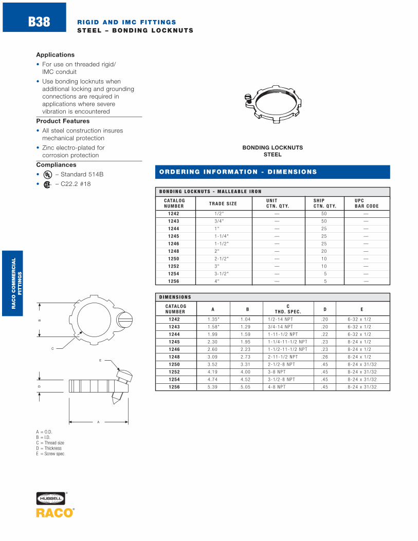
RIGID AND IMC FITTINGSSTEEL – BONDING LOCKNUTS
BONDING LOCKNUTS STEEL
CATALOG UNIT SH IP UPCNUMBER TRADE S IZE CTN . QTY. CTN . QTY. BAR CODE
1242 1/2" — 50 —
1243 3/4" — 50 —
1244 1" — 25 —
1245 1-1/4" — 25 —
1246 1-1/2" — 25 —
1248 2" — 20 —
1250 2-1/2" — 10 —
1252 3" — 10 —
1254 3-1/2" — 5 —
1256 4" — 5 —
B O N D I N G L O C K N U T S - M A L L E A B L E I R O N
A = O.D.B = I.D.C = Thread sizeD = ThicknessE = Screw spec
Applications
• For use on threaded rigid/IMC conduit
• Use bonding locknuts when additional locking and groundingconnections are required in applications where severe vibration is encountered
Product Features
• All steel construction insuresmechanical protection
• Zinc electro-plated for corrosion protection
Compliances
• – Standard 514B
• – C22.2 #18®
®
CATALOG CNUMBER A B THD. SPEC . D E
1242 1.35" 1.04 1/2-14 NPT .20 6-32 x 1 /2
1243 1.58" 1.29 3/4-14 NPT .20 6-32 x 1 /2
1244 1.99 1.59 1-11-1/2 NPT .22 6-32 x 1 /2
1245 2.30 1.95 1-1/4-11-1/2 NPT .23 8-24 x 1 /2
1246 2.60 2.23 1-1/2-11-1/2 NPT .23 8-24 x 1 /2
1248 3.09 2.73 2-11-1/2 NPT .26 8-24 x 1 /2
1250 3.52 3.31 2-1/2-8 NPT .45 8-24 x 31/32
1252 4.19 4.00 3-8 NPT .45 8-24 x 31/32
1254 4.74 4.52 3-1/2-8 NPT .45 8-24 x 31/32
1256 5.39 5.05 4-8 NPT .45 8-24 x 31/32
D I M E N S I O N S
ORDERING INFORMATION - DIMENSIONS
RA
CO
CO
MM
ER
CIA
L
FIT
TIN
GS
B38
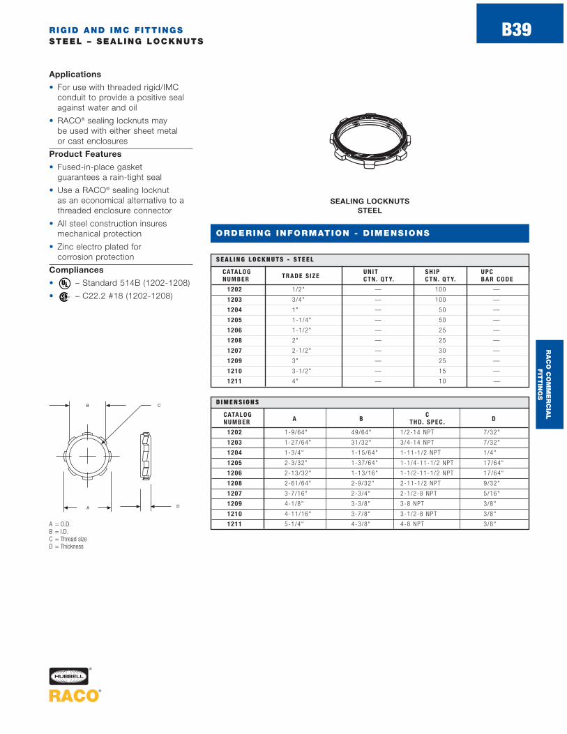
RIGID AND IMC FITTINGSSTEEL – SEALING LOCKNUTS
ORDERING INFORMATION - DIMENSIONS
Applications
• For use with threaded rigid/IMCconduit to provide a positive sealagainst water and oil
• RACO® sealing locknuts may be used with either sheet metal or cast enclosures
Product Features
• Fused-in-place gasket guarantees a rain-tight seal
• Use a RACO® sealing locknut as an economical alternative to athreaded enclosure connector
• All steel construction insuresmechanical protection
• Zinc electro plated for corrosion protection
Compliances
• – Standard 514B (1202-1208)
• – C22.2 #18 (1202-1208)®
®
SEALING LOCKNUTS STEEL
CATALOG UNIT SH IP UPCNUMBER TRADE S IZE CTN . QTY. CTN . QTY. BAR CODE
1202 1/2" — 100 —
1203 3/4" — 100 —
1204 1" — 50 —
1205 1-1/4" — 50 —
1206 1-1/2" — 25 —
1208 2" — 25 —
1207 2-1/2" — 30 —
1209 3" — 25 —
1210 3-1/2" — 15 —
1211 4" — 10 —
S E A L I N G L O C K N U T S - S T E E L
A = O.D.B = I.D.C = Thread sizeD = Thickness
CATALOG CNUMBER A B THD. SPEC . D
1202 1-9/64" 49/64" 1/2-14 NPT 7/32"
1203 1-27/64" 31/32" 3/4-14 NPT 7/32"
1204 1-3/4" 1-15/64" 1-11-1/2 NPT 1/4"
1205 2-3/32" 1-37/64" 1-1/4-11-1/2 NPT 17/64"
1206 2-13/32" 1-13/16" 1-1/2-11-1/2 NPT 17/64"
1208 2-61/64" 2-9/32" 2-11-1/2 NPT 9/32"
1207 3-7/16" 2-3/4" 2-1/2-8 NPT 5/16"
1209 4-1/8" 3-3/8" 3-8 NPT 3/8"
1210 4-11/16" 3-7/8" 3-1/2-8 NPT 3/8"
1211 5-1/4" 4-3/8" 4-8 NPT 3/8"
D I M E N S I O N S
RA
CO
CO
MM
ER
CIA
L
FIT
TIN
GS
B39
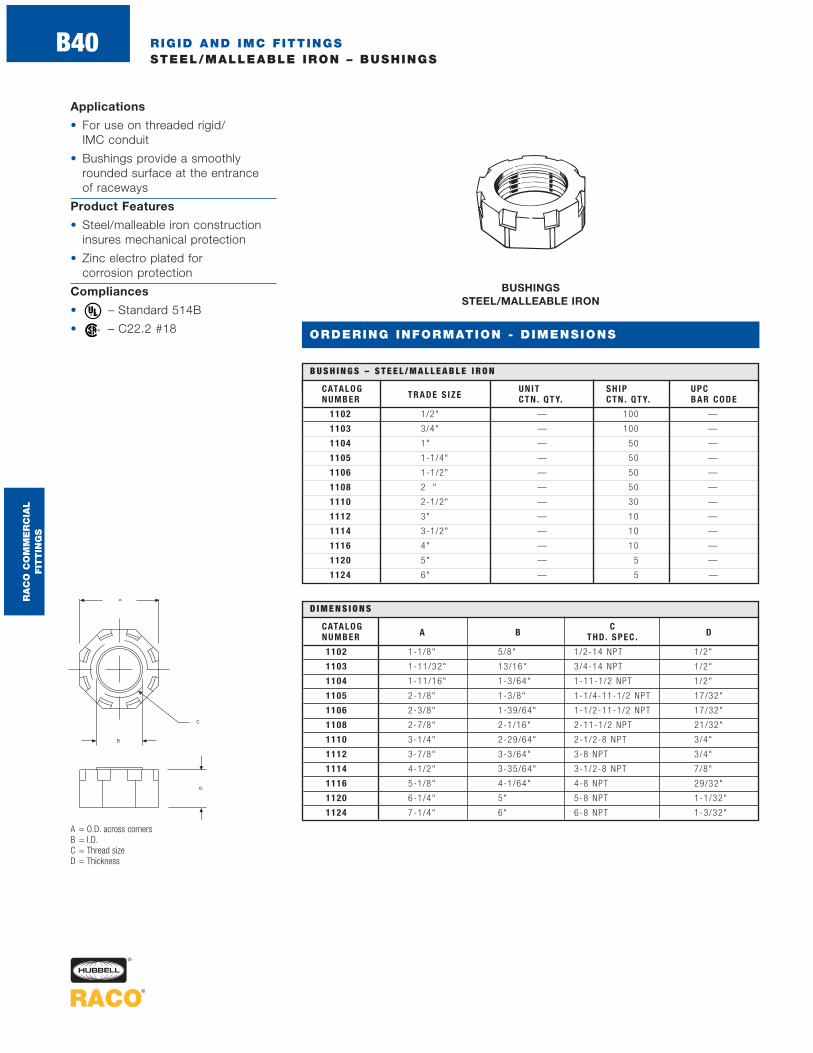
RIGID AND IMC FITTINGSSTEEL/MALLEABLE IRON – BUSHINGS
BUSHINGS STEEL/MALLEABLE IRON
CATALOG UNIT SH IP UPCNUMBER TRADE S IZE CTN . QTY. CTN . QTY. BAR CODE
1102 1/2" — 100 —
1103 3/4" — 100 —
1104 1" — 50 —
1105 1-1/4" — 50 —
1106 1-1/2" — 50 —
1108 2 " — 50 —
1110 2-1/2" — 30 —
1112 3" — 10 —
1114 3-1/2" — 10 —
1116 4" — 10 —
1120 5" — 5 —
1124 6" — 5 —
B U S H I N G S – S T E E L / M A L L E A B L E I R O N
A = O.D. across cornersB = I.D.C = Thread sizeD = Thickness
Applications
• For use on threaded rigid/ IMC conduit
• Bushings provide a smoothlyrounded surface at the entrance of raceways
Product Features
• Steel/malleable iron construction insures mechanical protection
• Zinc electro plated for corrosion protection
Compliances
• – Standard 514B
• – C22.2 #18®
®
CATALOG CNUMBER A B THD. SPEC . D
1102 1-1/8" 5/8" 1/2-14 NPT 1/2"
1103 1-11/32" 13/16" 3/4-14 NPT 1/2"
1104 1-11/16" 1-3/64" 1-11-1/2 NPT 1/2"
1105 2-1/8" 1-3/8" 1-1/4-11-1/2 NPT 17/32"
1106 2-3/8" 1-39/64" 1-1/2-11-1/2 NPT 17/32"
1108 2-7/8" 2-1/16" 2-11-1/2 NPT 21/32"
1110 3-1/4" 2-29/64" 2-1/2-8 NPT 3/4"
1112 3-7/8" 3-3/64" 3-8 NPT 3/4"
1114 4-1/2" 3-35/64" 3-1/2-8 NPT 7/8"
1116 5-1/8" 4-1/64" 4-8 NPT 29/32"
1120 6-1/4" 5" 5-8 NPT 1-1/32"
1124 7-1/4" 6" 6-8 NPT 1-3/32"
D I M E N S I O N S
ORDERING INFORMATION - DIMENSIONS
RA
CO
CO
MM
ER
CIA
L
FIT
TIN
GS
B40

RIGID AND IMC FITTINGSPOLYPROPYLENE – INSULATED BUSHINGS
ORDERING INFORMATION - DIMENSIONS
INSULATING BUSHINGS POLYPROPYLENE
CATALOG UNIT SH IP UPCNUMBER TRADE S IZE CTN . QTY. CTN . QTY. BAR CODE
1402 1/2" 100 400 —
1403 3/4" 100 400 —
1404 1" 50 200 —
1405 1-1/4" — 25 —
1406 1-1/2" — 25 —
1408 2" — 25 —
1410 2-1/2" — 10 —
1412 3" — 10 —
1414 3-1/2" — 5 —
1416 4" — 5 —
1420 5" — 5 —
1424 6" — 5 —
I N S U L AT I N G B U S H I N G S - P O LY P R O P Y L E N E
A = O.D.B = I.D.C = Thread sizeD = Thickness
Applications
• For use on threaded rigid/ IMC conduit
• Bushings provide a smoothlyrounded surface at the entrance of raceways
Product Feature
• Insulating bushings are made ofhigh impact polypropylene that istemperature rated at 105° C
Compliances
• – Standard 514B
• – C22.2 #18®
®
CATALOG CNUMBER A B THD. SPEC . D
1402 1-1/16" 19/32" 1/2-14 NPT 25/64"
1403 1-9/32" 51/64" 3/4-14 NPT 25/64"
1404 1-9/16" 1" 1-11-1/2 NPT 9/16"
1405 1-59/64" 1-21/64" 1-1/4-11-1/2 NPT 9/16"
1406 2-3/16" 1-35/64" 1-1/2-11-1/2 NPT 9/16"
1408 2-11/16" 2" 2-11-1/2 NPT 5/8"
1410 3-3/16" 2-13/32" 2-1/2-8 NPT 43/64"
1412 3-27/32" 3" 3-8 NPT 3/4"
1414 4-23/64" 3-13/32" 3-1/2-8 NPT 3/4"
1416 4-27/32" 3-29/32" 4-8 NPT 49/64"
1420 6-3/8" 4-59/64" 5-8 NPT 1"
1424 7-1/2" 5-57/64" 6-8 NPT 1"
D I M E N S I O N S
RA
CO
CO
MM
ER
CIA
L
FIT
TIN
GS
B41

RIGID AND IMC FITTINGSSTEEL/MALLEABLE IRON – INSULATED BUSHINGS
Application
• For use on threaded rigid/IMC conduit to provide a smoothlyrounded surface at the entrance of raceways
Product Features
• Insuliner temperature rated at 105° C
• Steel/malleable construction insures mechanical protection for the raceway
• Zinc electro plated for corrosionprotection
Compliances
• – Standard 514B
• – C22.2 #18®
®
INSULATED BUSHINGS STEEL/MALLEABLE IRON
CATALOG UNIT SH IP UPCNUMBER TRADE S IZE CTN . QTY. CTN . QTY. BAR CODE
1132 1/2" — 100 —
1133 3/4" — 50 —
1134 1" — 25 —
1135 1-1/4" — 25 —
1136 1-1/2" — 25 —
1138 2" — 10 —
1126 2-1/2" — 10 —
1127 3" — 5 —
1128 3-1/2" — 5 —
1129 4" — 5 —
I N S U L AT E D B U S H I N G S - S T E E L / M A L L E A B L E I R O N
A = O.D. across cornersB = I.D.C = Thread sizeD = Thickness
CATALOG CNUMBER A B THD. SPEC . D
1132 1-1/8" 9/16" 1/2-14 NPT 17/32"
1133 1-11/32" 3/4" 3/4-14 NPT 17/32"
1134 1-11/16" 31/32" 1-11-1/2 NPT 17/32"
1135 2-1/8" 1-1/4" 1-1/4-11-1/2 NPT 37/64"
1136 2-3/8" 1-15/32" 1-1/2-11-1/2 NPT 37/64"
1138 2-7/8" 1-31/32" 2-11-1/2 NPT 45/64"
1126 3-1/4" 2-23/64" 2-1/2-8 NPT 27/32"
1127 3-7/8" 2-59/64" 3-8 NPT 27/32"
1128 4-1/2" 3-3/8" 3-1/2-8 NPT 1"
1129 5-1/8" 3-27/32" 4-8 NPT 1-1/32"
D I M E N S I O N S
ORDERING INFORMATION - DIMENSIONS
RA
CO
CO
MM
ER
CIA
L
FIT
TIN
GS
B42

RIGID AND IMC FITTINGSSTEEL/MALLEABLE IRON – INSULATED GROUNDING BUSHINGS
INSULATED GROUNDING BUSHINGS – LAY-IN LUG STEEL/MALLEABLE IRON
UNIT SH IP GROUNDING UPCCATALOG T RADE CT N . CT N . WIRE CAPAC IT Y BARNUMBER S IZE QT Y. QT Y. MIN . MAX . CODE
1212 1/2" — 100 #14 So l . #4 S t r. —
1213 3/4" — 100 #14 So l . #4 S t r. —
1214 1" — 50 #14 So l . #4 S t r. —
1215 1-1/4" — 25 #14 So l . #4 S t r. —
1216 1-1/2" — 25 #14 So l . #4 S t r. —
1218 2" — 10 #14 So l . #4 S t r. —
1290 2-1/2" — 10 #14 So l . #1/0 S t r. —
1292 3" — 5 #14 So l . #1/0 S t r. —
1294 3-1/2" — 5 #6 S t r. #250 MCM —
1296 4" — 5 #6 S t r. #250 MCM —
I N S U L AT E D G R O U N D I N G B U S H I N G S – L AY- I N L U G S T E E L - M A L L E A B L E I R O N
A = O.D. across corners G = Screw spec, bondingB = I.D. screwC = Thread size H = Screw spec, screw thatD = Thickness holds lug to bushingE = Height of lug I = Screw spec, screw thatF = Width of lug holds ground wire
Application
• For use on threaded rigid/IMC conduit to provide a means ofgrounding conduit through an insulated bushing
Product Features
• Lay-in lug style provides an easymeans of inserting a ground wire
• Dual rated aluminum grounding lugs may be used with copper oraluminum grounding conductors
• Insuliner temperature rated at 105° C
• Steel/malleable construction insures mechanical protection forthe raceway
• Zinc electro plated for corrosionprotection
Compliance
• – Standard 514B ®
CATALOG CNUMBER A B THD. SPEC . D E F G H I
1212 1-1/8" 9/16" 1/2-14 NPS 17/32" 1-1/16" 3/8"10-32 x 1 /4" 10-32 x 1 /4" 1/4-28 x 5 /8"Se t Sc rew Pan Head Screw Set Screw
1213 1-11/32" 3/4" 3/4-14 NPS 17/32" 1-1/16" 3/8"10-32 x 1 /4" 10-32 x 1 /4" 1/4-28 x 5 /8"Se t Sc rew Pan Head Screw Set Screw
1214 1-11/16" 31/32" 1-11-1/2 NPS 17/32" 1-1/16" 3/8"10-32 x 1 /4" 10-32 x 1 /4" 1/4-28 x 5 /8"Se t Sc rew Pan Head Screw Set Screw
1215 2-1/8" 1-1/4" 1-1/4-11-1/2 NPS 37/64" 1-1/16" 3/8"10-32 x 1 /4" 10-32 x 1 /4" 1/4-28 x 5 /8"Se t Sc rew Pan Head Screw Set Screw
1216 2-3/8” 1-15/32” 1-1/2-11-1/2 NPS 37/64" 1-1/16" 3/8"10-32 x 1 /4" 10-32 x 1 /4" 1/4-28 x 5 /8"Se t Sc rew Pan Head Screw Set Screw
1218 2-7/8" 1-31/32" 2-11-1/2 NPS 45/64" 1-1/16" 3/8"10-32 x 1 /4" 10-32 x 1 /4" 1/4-28 x 5 /8"Se t Sc rew Pan Head Screw Set Screw
1290 3-1/4" 2-23/64" 2-1/2-8 NPS 27/32“ 1-1/2" 19/32"10-32 x 5 /16" 1/4-20 x 3 /8" 3/8-24 x 7 /8"Se t Sc rew Pan Head Screw Set Screw
1292 3-7/8" 2-59/64" 3-8 NPS 27/32" 1-1/2" 19/32"10-32 x 5 /16" 1/4-20 x 3 /8" 3/8-24 x 7 /8"Se t Sc rew Pan Head Screw Set Screw
1294 4-1/2" 3-3/8" 3-1/2-8 NPS 1" 2-13/64" 51/64"5/16-24 x 3 /8" 5/16-24 x 17/32" 9/16-18 x 1-1/4"Se t Sc rew Pan Head Screw Set Screw
1296 5-1/8" 3-27/32" 4-8 NPS 1-1/32" 2-13/64" 51/64"5/16-24 x 7 /16" 5/16-24 x 17/32" 9/16 18 x 1-1/4"Se t Sc rew Pan Head Screw Set Screw
D I M E N S I O N S
ORDERING INFORMATION - DIMENSIONS
RA
CO
CO
MM
ER
CIA
L
FIT
TIN
GS
B43

RIGID AND IMC FITTINGSSTEEL/MALLEABLE IRON – INSULATED GROUNDING BUSHINGS
INSULATED GROUNDING BUSHINGS – FEED-THRU LUG STEEL/MALLEABLE IRON
UNIT SH IP GROUNDING UPCCATALOG T RADE CT N . CT N . . W IRE CAPAC IT Y BARNUMBER S IZE QTY. QTY. MIN . MAX . CODE
1222 1/2" — 100 #14 So l . #4 S t r. —
1223 3/4" — 100 #14 So l . #4 S t r. —
1224 1" — 50 #14 So l . #4 S t r. —
1225 1-1/4" — 25 #14 So l . #4 S t r. —
1226 1-1/2" — 25 #14 So l . #4 S t r. —
1228 2" — 10 #14 So l . #4 S t r. —
1230 2-1/2" — 10 #14 So l . #1/0 S t r. —
1232 3" — 5 #14 So l . #1/0 S t r. —
1234 3-1/2" — 5 #6 S t r. #250 MCM —
1236 4" — 5 #6 S t r. #250 MCM —
I N S U L AT E D G R O U N D I N G B U S H I N G S – F E E D - T H R U L U G - S T E E L - M A L L E A B L E I R O N
A = O.D. G = Screw spec bonding B = I.D. screwC = Thread size H = Screw spec screw thatD = Thickness holds lug to bushingE = Height of lug I = Screw spec screw thatF = Width of lug holds ground wire
Application
• For use on threaded rigid/IMC conduit to provide a means ofgrounding conduit through an insulated bushing
Product Features
• Feed-thru lug style provides an easy means of inserting a ground wire
• Dual rated aluminum grounding lugs may be used with copper oraluminum grounding conductors
• Insuliner temperature rated at 105° C
• Steel/malleable construction insures mechanical protection for the raceway
• Zinc electro plated for corrosionprotection
Compliance
• – Standard 514B®
CATALOG CNUMBER A B THD. SPEC . D E F G H I
1222 1-1/8" 9/16" 1/2-14 NPS 17/32" 1-1/16" 1/2"10-32 x 1 /4" 10-32 x 7 /32" 1/4-28 x 3 /8"Se t Sc rew Pan Head Screw Set Screw
1223 1-11/32" 3/4" 3/4-14 NPS 17/32" 1-1/16" 1/2"10-32 x 1 /4" 10-32 x 7 /32" 1/4-28 x 3 /8"Se t Sc rew Pan Head Screw Set Screw
1224 1-11/16" 31/32" 1-11-1/2 NPS 17/32" 1-1/16" 1/2"10-32 x 1 /4" 10-32 x 1 /4" 1/4-28 x 3 /8"Se t Sc rew Pan Head Screw Set Screw
1225 2-1/8" 1-1/4" 1-1/4-11-1/2 NPS 37/64" 1-1/16" 1/2"10-32x 1/4" 10-32 x 1 /4" 1/4-28 x 3 /8"Se t Sc rew Pan Head Screw Set Screw
1226 2-3/8" 1-15/32" 1-1/2-11-1/2 NPS 37/64" 1-1/16" 1/2"10-32 x 1 /4" 10-32 x 1 /4" 1/4-28 x 3 /8"Se t Sc rew Pan Head Screw Set Screw
1228 2-7/8" 1-31/32" 2-11-1/2 NPS 45/64" 1-1/16" 1/2"10-32 x 1 /4" 10-32 x 1 /4" 1/4-28 x 3 /8"Se t Sc rew Pan Head Screw Set Screw
1230 3-1/4" 2-23/64" 2-1/2-8 NPS 27/32" 1-15/32" 5/8"5/16-24 x 3 /8" 5/16-24 x 3 /8" 7/16-20 x 3 /8"Se t Sc rew Pan Head Screw Set Screw
1232 3-7/8" 2-59/64" 3-8 NPS 27/32" 1-15/32" 5/8"5/16-24 x 3 /8" 5/16-24 x 3 /8" 7/16-20 x 3 /8"Se t Sc rew Pan Head Screw Set Screw
1234 4-1/2" 3-3/8" 3-1/2-8 NPS 1" 1-3/4" 27/32"5/16-24 x 3 /8" 5/16-24 x 27/64" 5/8-18 x 11/16"Se t Sc rew Pan Head Screw Set Screw
1236 5-1/8" 3-27/32" 4-8 NPS 1- 1/32" 1-3/4" 27/32"5/16-24 x 7 /16" 5/16-24 x 27/64" 5/8-18 x 11/16"Se t Sc rew Pan Head Screw Set Screw
D I M E N S I O N S
ORDERING INFORMATION - DIMENSIONS
RA
CO
CO
MM
ER
CIA
L
FIT
TIN
GS
B44

ORDERING INFORMATION - DIMENSIONS
UNIT SH IP GROUNDING UPCCATALOG TRADE CTN . CTN . WIRE CAPAC ITY BARNUMBER S IZEQTY. QTY. MIN . MAX . CODE
1262 1/2" — 100 #14 So l . #4 S t r. —
1263 3/4" — 100 #14 So l . #4 S t r. —
1264 1" — 50 #14 So l . #4 S t r. —
1265 1-1/4" — 25 #14 So l . #4 S t r. —
1266 1-1/2" — 25 #14 So l . #2 S t r. —
1267 2" — 10 #14 So l . #2 S t r. —
1268 2-1/2" — 10 #14 So l . 1 /0 —
1270 3" — 5 #14 So l . 1 /0 —
1272 3-1/2" — 5 #6 S t r. 250 MCM —
1274 4" — 5 #6 S t r. 250 MCM —
1 5 0 ° C I N S U L AT E D G R O U N D I N G B U S H I N G S – L AY- I N L U G - S T E E L / M A L L E A B L E I R O N
150° INSULATED GROUNDING BUSHINGS – FEED-THRU LUG STEEL/MALLEABLE IRON
Application
• For use on threaded rigid/IMC conduit to provide a means ofgrounding conduit through an insulated bushing
Product Features
• Lay-In style of grounding allows for easy insertion of groundingconnector
• Dual rated aluminum grounding lugs may be used with copper oraluminum grounding conductors
• Insuliner temperature rated at 150° C will not soften or becomedislodged during wire pulling
• Malleable construction insures mechanical protection for the raceway
• Zinc electro plated for corrosion protection
Compliances
• – Standard 514B
• – C22.2 #18®
®
RIGID AND IMC FITTINGSMALLEABLE IRON – 150°C INSULATED GROUNDING BUSHINGS
CATALOG TRADENUMBER S IZE A B C
1262 1/2" 1 .34 1.19 .61
1263 3/4" 1 .47 1.45 .64
1264 1" 1.63 1.76 .72
1265 1-1/4" 1 .80 2.10 .74
1266 1-1/2" 2 .11 2.33 .80
1267 2" 2.34 2.79 .85
1268 2-1/2" 2 .84 3.33 1.10
1270 3" 3.11 3.87 1.10
1272 3-1/2" 4 .02 4.42 1.10
1274 4" 4.25 4.89 1.10
D I M E N S I O N S
A = Lug Bushing WidthB = O.D. BushingC = Thickness
RA
CO
CO
MM
ER
CIA
L
FIT
TIN
GS
B45

RIGID AND IMC FITTINGSSTEEL – STRAPS
ORDERING INFORMATION - DIMENSIONS
Applications
• For use in mounting rigid/IMC conduit in wet or dry locations
• RACO® Rigid/IMC conduit straps are suitable for use on liquidtight flexible metal conduitand liquidtight flexible nonmetallicconduit (type B)
Product Features
• All steel construction insuresmechanical protection
• RACO® steel one-hole straps snap on to conduit, allowing the installer to easily position the strap before mounting
• All straps are zinc electro platedfor corrosion protection
ONE HOLE PUSH-ON STRAPS STAMPED STEEL
CATALOG UNIT SH IP UPCNUMBER TRADE S IZE CTN . QTY. CTN . QTY. BAR CODE
1332 1/2" 100 500 —
1333 3/4" 100 500 —
1334 1" 50 250 —
1335 1-1/4" 25 100 —
1336 1-1/2" — 25 —
1338 2" — 25 —
1337 2-1/2" — 25 —
1339 3" — 25 —
1340 3-1/2" — 10 —
1341 4" — 10 —
O N E H O L E P U S H - O N S T R A P S - S TA M P E D S T E E L
A = Overall lengthB = HeightC = Hole sizeD = DiameterE = Width of strap
CATALOGNUMBER A B C D E
1332 1-59/64" 7/8" 9/32" 55/64" 7/8"
1333 2-5/16" 1-3/32" 9/32" 1-1/16" 3/4"
1334 2-11/16" 1-1/4" 9/32" 1-5/16" 3/4"
1335 3-1/8" 1-5/8" 11/32" 1-5/8" 7/8"
1336 3-27/32" 1-7/8" 13/32" 1-15/16" 7/8"
1338 4-9/16" 2-7/16" 13/32" 2-3/8" 7/8"
1337 5-5/16" 3" 21/32" 2-7/8" 1-1/4"
1339 6-1/16" 3-9/16" 21/32" 3-1/2" 1-1/4"
1340 6-7/8" 3-7/8" 21/32" 4" 1-1/4"
1341 7-3/8" 4-1/4" 21/32" 4-1/2" 1-1/4"
D I M E N S I O N S
RA
CO
CO
MM
ER
CIA
L
FIT
TIN
GS
B46

RIGID AND IMC FITTINGSMALLEABLE IRON – STRAPS
ORDERING INFORMATION - DIMENSIONS
ONE HOLE STRAPS MALLEABLE IRON
CATALOG UNIT SH IP UPCNUMBER TRADE S IZE CTN . QTY. CTN . QTY. BAR CODE
1301 3/8" — 100 —
1302 1/2" — 100 —
1303 3/4" — 100 —
1304 1" — 50 —
1305 1-1/4" — 25 —
1306 1-1/2" — 25 —
1308 2" — 25 —
1310 2-1/2" — 10 —
1312 3" — 10 —
1314 3-1/2" — 5 —
1316 4" — 5 —
O N E H O L E S T R A P S - M A L L E A B L E I R O N
A = Overall lengthB = HeightC = Hole sizeD = DiameterE = Width of strap
Applications
• For use in mounting rigid/IMC conduit in wet or dry locations
• RACO® Rigid/IMC conduit straps are suitable for use on liquidtight flexible metal conduitand liquidtight flexible nonmetallicconduit (type B)
Product Features
• All malleable construction insuresmechanical protection
• All straps are zinc electro platedfor corrosion protection
CATALOGNUMBER A B C D E
1301 1-7/8" 25/32" 11/32" 11/16" 21/32"
1302 2-3/32" 7/8" 11/32" 7/8" 3/4"
1303 2-1/2" 1-3/32" 11/32" 1-5/64" 25/32"
1304 2-25/32" 1-13/32" 3/8" 1-11/32" 15/16"
1305 3-21/64" 1-43/64" 15/32" 1-11/16" 1"
1306 3-15/16" 2" 13/32" 1-15/16" 1-1/8"
1308 4-5/8" 2-9/16" 19/32" 2-3/8" 1-7/16"
1310 6-7/16" 3-9/32" 21/32" 2-7/8" 1-13/16"
1312 7-1/2" 4" 21/32" 3-1/2" 2"
1314 8-1/8" 4-1/2" 53/64" 4" 2-1/8"
1316 8-7/8" 5-5/16" 3/4" 4-1/2" 2-1/4"
D I M E N S I O N S
RA
CO
CO
MM
ER
CIA
L
FIT
TIN
GS
B47

RIGID AND IMC FITTINGSSTEEL – STRAPS
ORDERING INFORMATION - DIMENSIONS
TWO HOLE STRAPS STAMPED STEEL
CATALOG UNIT SH IP UPCNUMBER TRADE S IZE CTN . QTY. CTN . QTY. BAR CODE
2232 1/2" — 100 —
2233 3/4" — 100 —
2234 1" — 100 —
2235 1-1/4" — 100 —
2236 1-1/2" — 50 —
2238 2" — 25 —
2239 2-1/2" — 25 —
2240 3" — 25 —
2241 3-1/2" — 25 —
2242 4" — 10 —
2245-2 5" — 5 —
2246-2 6" — 5 —
T W O H O L E S T R A P S - S TA M P E D S T E E L
A = Overall lengthB = Overall heightC = Strap widthD = Hole diameterE = Diameter
Applications
• For use in mounting rigid/IMC conduit in wet or dry locations
• RACO® Rigid/IMC conduit straps are suitable for use on liquidtight flexible metal conduitand liquidtight flexible nonmetallicconduit (type B)
Product Features
• All steel construction insuresmechanical protection
• All straps are zinc electro platedfor corrosion protection
CATALOGNUMBER A B C D E
2232 2-9/16" 7/8" 19/32" 3/16" 13/16"
2233 2-3/8" 1-1/8" 19/32" 3/16" 1-1/16"
2234 2-15/16" 1-31/32" 23/32" 1/4" 1-5/16"
2235 3-3/4" 1-11/16" 23/32" 1/4" 1-21/32"
2236 4-1/8" 1-7/8" 23/32" 1/4" 1-7/8"
2238 5" 2-7/16" 23/32" 17/64" 2-3/8"
2239 5-3/4" 3-1/8" 1" 5/16" 2-7/8"
2240 6-23/32" 3-11/16" 1" 5/16" 3-35/64"
2241 7-1/2" 3-15/16" 1" 5/16" 4-3/64"
2242 7-7/8" 4-11/16" 1" 5/16" 4-35/64"
2245-2 10-11/16" 5-43/64" 1-1/4" 21/32" 5-49/64"
2246-2 12-9/64" 6-19/32" 1-1/4" 21/32" 7"
D I M E N S I O N S
RA
CO
CO
MM
ER
CIA
L
FIT
TIN
GS
B48

RIGID AND IMC FITTINGSMALLEABLE IRON – CLAMP BACKS
ORDERING INFORMATION - DIMENSIONS
Applications
• For use with RACO® straps to permit space between the conduitand the mounting surface
• Use of clamp backs in outdoorlocations can prevent the buildupof snow and rain between the conduit and the mounting surface
Product Features
• All malleable construction insures durability and mechanicalprotection
• Elongated bolt holes make alignment with straps easy
• Zinc electro plated for corrosion protection
CLAMP BACKS MALLEABLE IRON
CATALOG TRADE S IZE UN IT SH IP UPCNUMBER RIG ID S IZE EMT S IZE CT N . QT Y. CT N . QT Y. BAR CODE
1342 1/2" 3/4" — 100 —
1343 3/ 4" 1" — 100 —
1344 1" 1-1/4" — 50 —
1345 1-1/4" 1-1/2" — 25 —
1346 1-1/2" 2" — 25 —
1348 2" 2" — 10 —
1347 2-1/2" 2-1/2" — 10 —
1349 3" 3" — 10 —
1350 3-1/2" 3-1/2" — 5 —
1351 4" 4" — 5 —
C L A M P B A C K S - M A L L E A B L E I R O N
A = Overall lengthB = WidthC = Hole diameterD = Slot sizeE = Height
CATALOGNUMBER A B C D E
1342 2-5/16" 1" 13/32" 3/8 x 9 /16" 7/16"
1343 2-3/8" 1-1/32" 13/32" 7/16 x 9 /16" 7/16"
1344 3" 1-1/4" 3/8" 15/32 x 19/32" 9/16"
1345 3-5/8" 1-15/32" 15/32" 1/2 x 3 /4" 11/16"
1346 3-29/32" 1-9/16" 7/16" 7/16 x 25/32" 1/2"
1348 4-3/4" 1-15/16" 9/16" 5/8 x 29/32" 31/32"
1347 5-7/8" 2-3/8" 1/2" 3/4 x 1" 7/8"
1349 6-3/4" 2-9/16" 1/2" 3/4 x 1" 7/8"
1350 7-5/16" 2-13/16" 1/2" 3/4 x 1" 1"
1351 8-9/32" 2-15/16" 1/2" 3/4 x 1" 1"
D I M E N S I O N S
RA
CO
CO
MM
ER
CIA
L
FIT
TIN
GS
B49
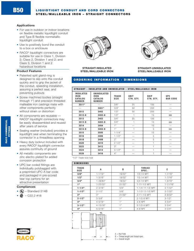
Applications
• For use in outdoor or indoor locationson flexible metallic liquidtight conduitand Type B flexible nonmetallic liquidtight conduit
• Use to positively bond the conduit to a box or enclosure
• RACO® liquidtight connectors aresuitable for use in Class 1, Division 2; Class 2, Division 1 and 2; andClass 3, Division 1 and 2 hazardous locations
Product Features
• Patented split gland-ring is designed to slip onto the conduitquickly and to grip the jacket of the conduit, speeding installation,assuring a perfect seal, and preventing pullouts
• Screw machined bodies (straightthrough 1") and precision threadedmalleable iron castings mate withother components perfectly without strain or distortion
• All components are reusable —RACO® liquidtight connectors may be easily disassembled and reusedafter years of service
• Sealing washer (included) provides aliquidtight seal when terminating theconnector in a threadless opening
• Heavy duty locknut included withevery RACO® liquidtight connectorassures continuity of ground
• All metallic components are zinc electro plated for added corrosion protection
• UPC bar coded fittings are individually polybagged with a preprinted UPC-A bar code and packaged in pre-scored tear top cartons for an attractive presentation
Compliances
• – Standard 514B
• – C22.2 #18®
®
LIQUIDTIGHT CONDUIT AND CORD CONNECTORSSTEEL/MALLEABLE IRON – STRAIGHT CONNECTORS
STRAIGHT-INSULATED STEEL/MALLEABLE IRON
A = Nut FlatsB = Thread length and thread spec.C = Overall length
TRADE T HREADS IZE A B SPEC . C
3/8" 1-1/16" 19/32” 1/2-14 NPT 1-7/16"
1/2" 1-3/16" 19/32” 1/2-14 NPT 1-7/16"
3/4" 1-29/64" 19/32” 3/4-14 NPT 1-9/16"
1" 1-23/32" 21/32” 1-11-1/2 NPT 1-11/16"
1-1/4" 2-3/16" 5/8” 1-1/4-11-1/2 NPT 2-1/32"
1-1/2" 2-1/2" 5/8” 1-1/2-11-1/2 NPT 2-7/32"
2" 3" 21/32” 2-11-1/2 NPT 2-9/32"
2-1/2" 3-5/8" 1” 2-1/2-8 NPT 3-1/2"
3" 4-5/16" 1” 3-8 NPT 3-3/4"
3-1/2" 4-13/16" 1” 3-1/2-8 NPT 3-3/4"
4" 5-5/16" 1” 4-8 NPT 3-3/4"
D I M E N S I O N S
ORDERING INFORMATION - DIMENSIONS
INSULATED UNINSULATEDIRON IRON TRADE UNIT SH IP UPCCATALOG CATALOG S IZE CTN . QTY. CTN . QTY. BAR CODENUMBER NUMBER
3511* — 3/8" 25 100 —
— 3401* 3/ 8" 50 200 —
3512 3402 1/2" 50 200 —
3512-8 3402-8 1/2" 1 15
3513 3403 3/4" 25 100 —
3513-8 3403-8 3/4" 1 10
3514 3404 1" — 10 —
3514-8 3404-8 1" 1 5
3515 3505 1-1/ 4” — 10 —
3516 3406 1-1/2" — 5 —
3518 3408 2" — 5 —
3520 3410 2-1/2" — 1 —
3522 3412 3" — 1 —
3524 3414 3-1/2" — 1 —
3526 3416 4" — 1 —
S T R A I G H T - I N S U L AT E D A N D U N I N S U L AT E D - S T E E L / M A L L E A B L E I R O N
STRAIGHT-UNINSULATED STEEL/MALLEABLE IRON
RA
CO
CO
MM
ER
CIA
L
FIT
TIN
GS
B50
*1/2" Trade s i ze hub
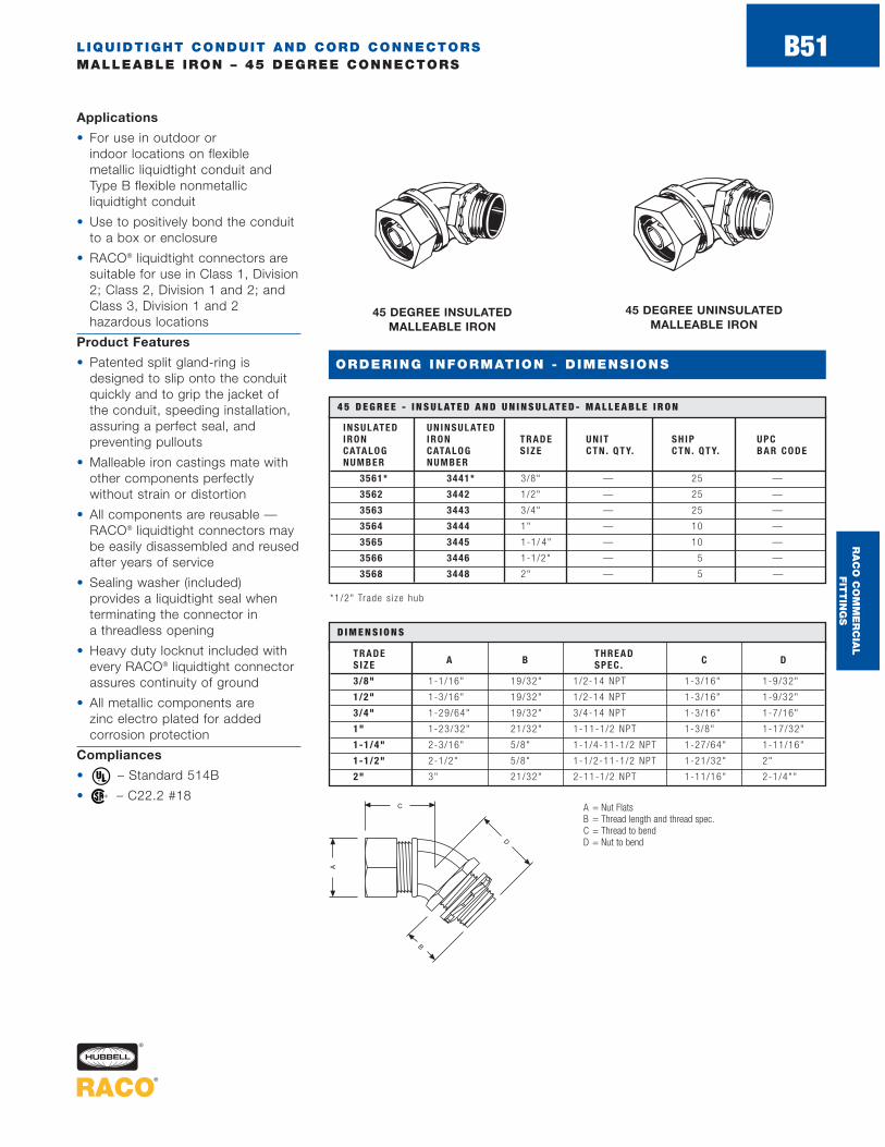
LIQUIDTIGHT CONDUIT AND CORD CONNECTORSMALLEABLE IRON – 45 DEGREE CONNECTORS
B51
ORDERING INFORMATION - DIMENSIONS
Applications
• For use in outdoor or indoor locations on flexible metallic liquidtight conduit andType B flexible nonmetallic liquidtight conduit
• Use to positively bond the conduitto a box or enclosure
• RACO® liquidtight connectors aresuitable for use in Class 1, Division2; Class 2, Division 1 and 2; andClass 3, Division 1 and 2 hazardous locations
Product Features
• Patented split gland-ring isdesigned to slip onto the conduitquickly and to grip the jacket ofthe conduit, speeding installation,assuring a perfect seal, and preventing pullouts
• Malleable iron castings mate withother components perfectly without strain or distortion
• All components are reusable —RACO® liquidtight connectors maybe easily disassembled and reusedafter years of service
• Sealing washer (included) provides a liquidtight seal whenterminating the connector in a threadless opening
• Heavy duty locknut included withevery RACO® liquidtight connectorassures continuity of ground
• All metallic components are zinc electro plated for added corrosion protection
Compliances
• – Standard 514B
• – C22.2 #18®
®
45 DEGREE INSULATED MALLEABLE IRON
A = Nut FlatsB = Thread length and thread spec.C = Thread to bendD = Nut to bend
TRADE T HREADS IZE A B SPEC . C D
3/8" 1-1/16" 19/32" 1/2-14 NPT 1-3/16" 1-9/32"
1/2" 1-3/16" 19/32" 1/2-14 NPT 1-3/16" 1-9/32"
3/4" 1-29/64" 19/32" 3/4-14 NPT 1-3/16" 1-7/16"
1" 1-23/32" 21/32" 1-11-1/2 NPT 1-3/8" 1-17/32"
1-1/4" 2-3/16" 5/8" 1-1/4-11-1/2 NPT 1-27/64" 1-11/16"
1-1/2" 2-1/2" 5/8" 1-1/2-11-1/2 NPT 1-21/32" 2"
2" 3" 21/32" 2-11-1/2 NPT 1-11/16" 2-1/4""
D I M E N S I O N S
45 DEGREE UNINSULATED MALLEABLE IRON
INSULATED UNINSULATEDIRON IRON TRADE UNIT SH IP UPCCATALOG CATALOG S IZE CTN . QTY. CTN . QTY. BAR CODENUMBER NUMBER
3561* 3441* 3/8" — 25 —
3562 3442 1/2" — 25 —
3563 3443 3/4" — 25 —
3564 3444 1" — 10 —
3565 3445 1-1/ 4" — 10 —
3566 3446 1-1/2" — 5 —
3568 3448 2" — 5 —
4 5 D E G R E E - I N S U L AT E D A N D U N I N S U L AT E D - M A L L E A B L E I R O N
RA
CO
CO
MM
ER
CIA
L
FIT
TIN
GS
*1/2" Trade s i ze hub
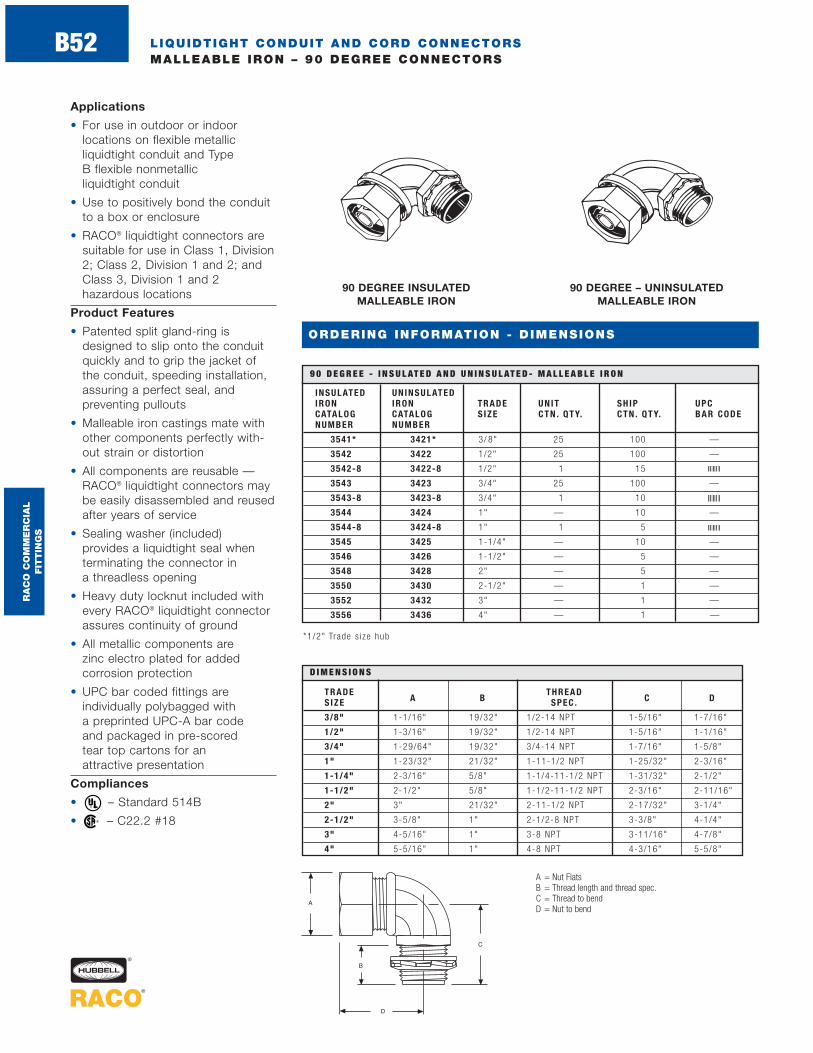
LIQUIDTIGHT CONDUIT AND CORD CONNECTORSMALLEABLE IRON – 90 DEGREE CONNECTORS
ORDERING INFORMATION - DIMENSIONS
Applications
• For use in outdoor or indoor locations on flexible metallic liquidtight conduit and Type B flexible nonmetallic liquidtight conduit
• Use to positively bond the conduitto a box or enclosure
• RACO® liquidtight connectors aresuitable for use in Class 1, Division2; Class 2, Division 1 and 2; andClass 3, Division 1 and 2 hazardous locations
Product Features
• Patented split gland-ring isdesigned to slip onto the conduitquickly and to grip the jacket ofthe conduit, speeding installation,assuring a perfect seal, and preventing pullouts
• Malleable iron castings mate withother components perfectly with-out strain or distortion
• All components are reusable —RACO® liquidtight connectors maybe easily disassembled and reusedafter years of service
• Sealing washer (included) provides a liquidtight seal whenterminating the connector in a threadless opening
• Heavy duty locknut included withevery RACO® liquidtight connectorassures continuity of ground
• All metallic components are zinc electro plated for added corrosion protection
• UPC bar coded fittings are individually polybagged with a preprinted UPC-A bar code and packaged in pre-scored tear top cartons for an attractive presentation
Compliances
• – Standard 514B
• – C22.2 #18®
®
90 DEGREE INSULATED MALLEABLE IRON
A = Nut FlatsB = Thread length and thread spec.C = Thread to bendD = Nut to bend
TRADE T HREADS IZE A B SPEC . C D
3/8" 1-1/16" 19/32" 1/2-14 NPT 1-5/16" 1-7/16"
1/2" 1-3/16" 19/32" 1/2-14 NPT 1-5/16" 1-1/16"
3/4" 1-29/64" 19/32" 3/4-14 NPT 1-7/16" 1-5/8"
1" 1-23/32" 21/32" 1-11-1/2 NPT 1-25/32" 2-3/16"
1-1/4" 2-3/16" 5/8" 1-1/4-11-1/2 NPT 1-31/32" 2-1/2"
1-1/2" 2-1/2" 5/8" 1-1/2-11-1/2 NPT 2-3/16" 2-11/16"
2" 3" 21/32" 2-11-1/2 NPT 2-17/32" 3-1/4"
2-1/2" 3-5/8" 1" 2-1/2-8 NPT 3-3/8" 4-1/4"
3" 4-5/16" 1" 3-8 NPT 3-11/16" 4-7/8"
4" 5-5/16" 1" 4-8 NPT 4-3/16" 5-5/8"
D I M E N S I O N S
90 DEGREE – UNINSULATED MALLEABLE IRON
INSULATED UNINSULATEDIRON IRON TRADE UNIT SH IP UPCCATALOG CATALOG S IZE CTN . QTY. CTN . QTY. BAR CODENUMBER NUMBER
3541* 3421* 3/ 8" 25 100 —
3542 3422 1/2" 25 100 —
3542-8 3422-8 1/2" 1 15
3543 3423 3/4" 25 100 —
3543-8 3423-8 3/4" 1 10
3544 3424 1" — 10 —
3544-8 3424-8 1" 1 5
3545 3425 1-1/4" — 10 —
3546 3426 1-1/2" — 5 —
3548 3428 2" — 5 —
3550 3430 2-1/2" — 1 —
3552 3432 3" — 1 —
3556 3436 4" — 1 —
9 0 D E G R E E - I N S U L AT E D A N D U N I N S U L AT E D - M A L L E A B L E I R O N
RA
CO
CO
MM
ER
CIA
L
FIT
TIN
GS
B52
*1/2" Trade s i ze hub

LIQUIDTIGHT CONDUIT AND CORD CONNECTORSSTEEL/MALLEABLE IRON – STRAIGHT CONNECTORS GROUNDING TYPE
B53
ORDERING INFORMATION - DIMENSIONS
Applications
• For use in outdoor or indoor locationson flexible metallic liquidtight conduit,when installation of a copper or aluminum external bonding jumper is required
• RACO® grounding liquidtight connectors are suitable for use in Class 1, Division 2; Class 2,Division 1 and 1; and Class 3,Division 1 and 2 hazardous locations
Product Features
• Patented split gland-ring is designed to slip onto the conduitquickly and to grip the jacket of the conduit, speeding installation,assuring a perfect seal, and preventing pullouts
• Screw machined bodies (straight through 1") and precision threadedmalleable iron castings mate withother components perfectly withoutstrain or distortion
• All components are reusable —RACO® liquidtight connectors may beeasily disassembled and reused afteryears of service
• Sealing washer (included) provides aliquidtight seal when terminating theconnector in a threadless opening
• Heavy duty locknut included withevery RACO® liquidtight connectorassures continuity of ground
• All metallic components are zinc electro plated for added corrosion protection
Compliances
• – Standard 514B
• – C22.2 #18®
®
STRAIGHT - INSULATED WITH GROUND LUG
STEEL/MALLEABLE IRON
CATALOG UNIT. SH IP. GROUNDING UPC
NUMBER TRADE S IZE CTN . QTY. CTN . QTY.WIRE CAPAC ITY BAR MIN . MAX . CODE
3511-3 * 3/8" — 25 #14 SOL. #4 STR. —
3512-3 1/2" — 25 #14 SOL. #4 STR. —
3513-3 3/4" — 25 #14 SOL. #4 STR. —
3514-3 1" — 10 #14 SOL. #4 STR. —
3515-3 1-1/ 4" — 10 #14 SOL. #4 STR. —
3516-3 1-1/2" — 5 #14 SOL. #4 STR. —
3518-3 2" — 5 #14 SOL. #4 STR. —
3520-3 2-1/2" — 1 #14 SOL. #110 STR. —
3522-3 3" — 1 #14 SOL. #110 STR. —
3524-3 3-1/2" — 1 #6 STR. #250 MCM —
3526-3 4" — 1 #6 STR. #250 MCM —
S T R A I G H T - I N S U L AT E D W I T H G R O U N D L U G S T E E L / M A L L E A B L E I R O N
A= Nut FlatsB = Thread length and thread spec.C = Overall lengthD = Lug height
TRADE T HREADS IZE A B SPEC . C D
3/8" 1-3/16" 19/32" 1/2-14 NPT 1-7/16" 25/32"
1/2" 1-5/16" 19/32" 1/2-14 NPT 1-7/16" 25/32"
3/4" 1-9/16" 19/32" 3/4-14 NPT 1-9/16" 25/32"
1" 1-27/32" 21/32" 1-11-1/2 NPT 1-11/16" 25/32"
1-1/4" 2-3/16" 5/8" 1-1/4-11-1/2 NPT 2-1/32" 25/32"
1-1/2" 2-1/2" 5/8" 1-1/2-11-1/2 NPT 2-7/32" 25/32"
2" 3" 2-1/32" 2-11-1/2 NPT 2-9/32" 25/32"
2-1/2" 3-5/8" 1" 2-1/2-8 NPT 3-1/2" 1-11/64"
3" 4-5/16" 1" 3-8 NPT 3-3/4" 1-11/64"
3-1/2" 4-13/16" 1" 3-1/2-8 NPT 3-3/4" 1-57/64"
4" 5-5/16" 1" 4-8 NPT 3-3/4" 1-57/64"
D I M E N S I O N S
RA
CO
CO
MM
ER
CIA
L
FIT
TIN
GS
*1/2" Trade s i ze hub

LIQUIDTIGHT CONDUIT AND CORD CONNECTORSSTEEL/MALLEABLE IRON – 45 DEGREE CONNECTORS GROUNDING TYPE
B54
ORDERING INFORMATION - DIMENSIONS
45 DEGREE - INSULATED WITH GROUND LUG MALLEABLE IRON
A = Nut FlatsB = Thread length and thread spec.C = Thread to bendD = Nut to bendE = Lug height
Applications
• For use in outdoor or indoor locations on flexible metallic liquidtight conduit, when installationof a copper or aluminum external bonding jumper is required
• RACO® grounding liquidtight connectors are suitable for use inClass 1, Division 2; Class 2, Division1 and 1; and Class 3, Division 1 and2 hazardous locations
Product Features
• Patented split gland-ring is designed to slip onto the conduitquickly and to grip the jacket of the conduit, speeding installation,providing a liquidtight seal, and preventing pullouts
• Malleable iron castings mate with other components perfectlywithout strain or distortion
• All components are reusable —RACO® liquidtight connectors may be easily disassembled and reusedafter years of service
• Sealing washer (included) provides aliquidtight seal when terminating theconnector in a threadless opening
• Heavy duty locknut included withevery RACO® liquidtight connectorassures continuity of ground
• All metallic components are zinc electro plated for added corrosion protection
Compliances
• – Standard 514B
• – C22.2 #18®
®
TRADE T HREADS IZE A B SPEC . C D E
3/8" 1-3/16" 19/32" 1/2-14 NPT 1-3/16" 1-9/32" 25/32"
1/2" 1-5/16" 19/32" 1/2-14 NPT 1-3/16" 1-9/32" 25/32"
3/4" 1-9/16" 19/32" 3/4-14 NPT 1-3/16" 1-7/16" 25/32"
1" 1-27/32" 21/32" 1-11-1/2 NPT 1-3/8" 1-17/32" 25/32"
1-1/4" 2-3/16" 5/8" 1-1/4-11-1/2 NPT 1-27/64" 1-11/16" 25/32"
1-1/2" 2-1/2" 5/8" 1-1/2-11-1/2 NPT 1-21/32" 2" 25/32"
2" 3" 21/32" 2-11-1/2 NPT 1-11/16" 2-1/4" 25/32"
D I M E N S I O N S
CATALOG UNIT. SH IP. GROUNDING UPC
NUMBER TRADE S IZE CTN . QTY. CTN . QTY.WIRE CAPAC ITY BAR MIN . MAX . CODE
3561-3* 3/ 8" — 25 #14 SOL. #4 STR. —
3562-3 1/2" — 25 #14 SOL. #4 STR. —
3563-3 3/4" — 25 #14 SOL. #4 STR. —
3564-3 1" — 10 #14 SOL. #4 STR. —
3565-3 1-1/4" — 10 #14 SOL. #4 STR. —
3566-3 1-1/2" — 5 #14 SOL. #4 STR. —
3568-3 2" — 5 #14 SOL. #4 STR. —
S T R A I G H T - I N S U L AT E D W I T H G R O U N D L U G S T E E L / M A L L E A B L E I R O N
RA
CO
CO
MM
ER
CIA
L
FIT
TIN
GS *1/2" Trade s i ze hub

LIQUIDTIGHT CONDUIT AND CORD CONNECTORSSTEEL/MALLEABLE IRON – 90 DEGREE CONNECTORS GROUNDING TYPE
B55
ORDERING INFORMATION - DIMENSIONS
90 DEGREE - INSULATED WITH GROUND LUG MALLEABLE IRON
A = Nut FlatsB = Thread length and thread spec.C = Thread to bendD = Nut to bendE = Lug height
Applications
• For use in outdoor or indoor locations on flexible metallic liquidtight conduit, when installationof a copper or aluminum externalbonding jumper is required
• RACO® grounding liquidtight connectors are suitable for use inClass 1, Division 2; Class 2, Division1 and 1; and Class 3, Division 1 and 2 hazardous locations
Product Features
• Patented split gland-ring is designed to slip onto the conduitquickly and to grip the jacket of the conduit, speeding installation,providing a liquidtight seal, and preventing pullouts
• Malleable iron castings mate with other components perfectlywithout strain or distortion
• All components are reusable —RACO® liquidtight connectors maybe easily disassembled and reusedafter years of service
• Sealing washer (included) provides aliquidtight seal when terminating theconnector in a threadless opening
• Heavy duty locknut included withevery RACO® liquidtight connectorassures continuity of ground
• All metallic components are zinc electro plated for added corrosion protection
Compliances
• – Standard 514B
• – C22.2 #18®
®
TRADE T HREADS IZE A B SPEC . C D E
3/8" 1-3/16" 19/32" 1/2-14 NPT 1 5/16" 1-7/16" 25/32"
1/2" 1-5/16" 19/32" 1/2-14 NPT 1-5/16" 1-7/16" 25/32"
3/4" 1-9/16" 19/32" 3/4-14 NPT 1-7/16" 1-5/8" 25/32"
1" 1-27/32" 21/32" 1-11-1/2 NPT 1-25/32" 2-3/16" 25/32"
1-1/4" 2-3/16" 5/8" 1-1/4-11-1/2 NPT 1-31/32" 2-1/2" 25/32"
1-1/2" 2-1/2" 5/8" 1-1/2-11-1/2 NPT 2-3/16" 2-11/16" 25/32"
2" 3" 21/32" 2-11-1/2 NPT 2-17/32" 3-1/4" 25/32"
2-1/2" 3-5/8" 1" 2-1/2-8 NPT 3-3/8" 4-1/4" 1-11/64"
3" 4-5/16" 1" 3-8 NPT 3-11/16" 4-7/8" 1-11/64"
4" 5-5/16" 1" 4-8 NPT 4-3/16" 5-5/8" 1-57/64"
D I M E N S I O N S
CATALOG UNIT. SH IP. GROUNDING UPC
NUMBER TRADE S IZE CTN . QTY. CTN . QTY.WIRE CAPAC ITY BAR MIN . MAX . CODE
3541-3* 3/ 8" — 25 #14 SOL. #4 STR. —
3542-3 1/2" — 25 #14 SOL. #4 STR. —
3543-3 3/4" — 25 #14 SOL. #4 STR. —
3544-3 1" — 10 #14 SOL. #4 STR. —
3545-3 1-1/4" — 10 #14 SOL. #4 STR. —
3546-3 1-1/2" — 5 #14 SOL. #4 STR. —
3548-3 2" — 5 #14 SOL. #4 STR. —
3550-3 2-1/2" — 1 #14 SOL. #4 STR. —
3552-3 3" — 1 #14 SOL. #4 STR. —
3556-3 4" — 1 #14 SOL. #4 STR. —
S T R A I G H T - I N S U L AT E D W I T H G R O U N D L U G S T E E L / M A L L E A B L E I R O N
RA
CO
CO
MM
ER
CIA
L
FIT
TIN
GS
*1/2" Trade s i ze hub

LIQUIDTIGHT CONDUIT AND CORD CONNECTORSSTEEL – SEALING WASHERS
B56
ORDERING INFORMATION - DIMENSIONS
Application
• For use whenever a positive seal is required between the shoulder of a fitting and an enclosure
Product Features
• One-piece construction assures proper installation — no need to worry about aligningmultiple components
• Steel ring is zinc electro plated for added corrosion protection
• UPC bar coded fittings are individually polybagged with a preprinted UPC-A bar code and packaged in pre-scored tear top cartons for an attractive presentation
Compliances
• – Standard 514B
• – C22.2 #18®
®
SEALING WASHERS*
CATALOG UNIT. SH IP. UPCNUMBER TRADE S IZE CTN . QTY. CTN . QTY. BAR CODE
2452 1/2" 50 100 —
2452-8 1/2" 2 25
2453 3/4" 25 50 —
2453-8 3/4" 2 20
2454 1" 25 50 —
2454-8 1" 2 10
2455 1-1/4" 5 25 —
2456 1-1/2" 5 25 —
2458 2" 5 25 —
S E A L I N G W A S H E R S *
A = O.D.B = I.D.C = Thickness
CONDUITS IZE A B C
1/2" 1-5/64" 5/64" 51/64"
3/4" 1-11/32" 5/32" 1"
1" 1-5/8" 11/64" 1-1/4"
1-1/4" 2" 11/64" 1-39/64"
1-1/2" 2-23/64" 3/16" 1-27/32"
2" 2-53/64" 3/16" 2-5/16"
D I M E N S I O N S *
*One-p iece s tee l r i ng and neoprene gaske t , ra in t igh t
*D imens ions when r ing and gaske t a re toge ther
RA
CO
CO
MM
ER
CIA
L
FIT
TIN
GS

Applications
• For use in dry or wet locationswhen the conduit and fittings arenot subject to physical damage
• Use Type B conduit and fittingswhenever flexibility is required for installation, operation, or maintenance
Product Features
• All gray nonmetallic constructionends metal fatigue and separationproblems
• Conduit cuts cleanly — speedsinstallation and ends the worry of jagged edges
• Each connector is supplied with aNeoprene o-ring and nylon locknut
• UPC bar coded fittings are individually polybagged with a preprinted UPC-A bar code and packaged in pre-scored tear top cartons for an attractive presentation
Compliances
• – Standard 1660 (conduit); Standard 514B (fittings)
• – C22.2 #18®
®
LIQUIDTIGHT CONDUIT AND CORD CONNECTORS NONMETALLIC – TYPE B CONDUIT AND CONNECTORS
B57
STRAIGHT CONNECTORS - NYLON FOR TYPE B CONDUIT
CATALOG FEET PER UPC .NUMBER TRADE S IZE PACKAGE BAR CODE
6701 3/ 8" 100 —
6702 1/2" 100 —
6703 3/4" 100 —
6704 1" 100 —
6705 1-1/4" 100 —
6706 1-1/2" 50 —
6708 2" 50 —
T Y P E B L I Q U I D T I G H T F L E X I B L E - N O N M E TA L L I C C O N D U I T
CATALOG UNIT. SH IP. UPCNUMBER TRADE S IZE CTN . QTY. CTN . QTY. BAR CODE
4721* 3/8" — 25 —
4722 1/2" — 25 —
4722-8 1/2" 1 20
4723 3/ 4" — 25 —
4723-8 3/ 4" 1 15
4724 1" — 10 —
4724-8 1" 1 10
4725 1-1/4" — 10 —
4726 1-1/2" — 5 —
4728 2" — 5 —
S T R A I G H T C O N N E C T O R S - N Y L O N - F O R T Y P E B C O N D U I T
TYPE B LIQUIDTIGHT FLEXIBLE NONMETALLIC CONDUIT
Type B Liquidtight FlexibleNonmetallic Conduit DimensionsTRADE CONDUIT BENDS IZE I .D. /O.D. RAD IUS
3/8" .49/ .70" 2.00"
1/2" .63/ .83" 3.00"
3/4" .83/1 .04" 4.00"
1" 1.05/1 .30" 5.00"
1-1/4" 1 .40/1 .65" 6.30"
1-1/2" 1 .59/1 .88" 7.50"
2" 2.03/2 .36" 10.00"
D I M E N S I O N S
TRADE E
S IZE A B C D A/C* A/F**
3/8" 1.14" 1.63" .57" .42" 1.41" 1.30"
1/2" 1 .30" 2.14" .57" .55" 1.41" 1.30"
3/4" 1 .53" 2.22" .58" .74" 1.85" 1.53"
1" 1.80" 2.32" .72" .96" 1.94" 1.80"
1-1/4" 2 .20" 2.15" .74" 1.30" 2.38" 2.18"
1-1/2" 2 .49" 2.35" .76" 1.46" 2.63" 2.43"
2" 3.05" 2.51" .79" 1.90" 3.13" 2.93"
D I M E N S I O N S
ORDERING INFORMATION - DIMENSIONS
* A /C=Across co rners**A/F=Across f l a t s
RA
CO
CO
MM
ER
CIA
L
FIT
TIN
GS
*1/2" Trade s i ze hub

LIQUIDTIGHT CONDUIT AND CORD CONNECTORS NONMETALLIC – SWIVEL LOK ® CONNECTORS FOR TYPE B NONMETALLIC CONDUIT
B58
ORDERING INFORMATION - DIMENSIONS
SWIVEL LOK® MULTI - POSITION CONNECTORS NYLON - FOR
TYPE B CONDUIT
CATALOG UNIT. SH IP. UPCNUMBER TRADE S IZE CTN . QTY. CTN . QTY. BAR CODE
4731* 3/ 8" — 25 —
4732 1/ 2" — 25 —
4732-8 1/ 2" 1 20
4733 3/ 4" — 25 —
4733-8 3/ 4" 1 15
4734 1" — 10 —
4734-8 1" 1 10
S W I V E L L O K ® M U LT I - P O S I T I O N C O N N E C T O R S - N Y L O N F O R T Y P E B C O N D U I T
TRADE H
S IZE F G A/C* A/F** I J K
3/8" 3.27" .57" 1.41" 1.30" 1.30" 1.43" 2.00"
1/2" 3.27" .57" 1.41" 1.30" 1.30" 1.43" 2.00"
3/4" 3.66" .58" 1.65" 1.53" 1.53" 1.59" 2.23"
1" 4.00" .72" 1.94" 1.80" 1.80" 1.84" 2.30"
D I M E N S I O N S
Swivel Lok® and 90 DegreeConnectors Applications
• For use in dry or wet locationswhen the conduit and fittings arenot subject to physical damage
• Use Type B conduit and fittingswhenever flexibility is required for installation, operation, or maintenance
Swivel Lok® and 90 DegreeConnectors Product Features
• All gray nonmetallic constructionprovides superior corrosion resistance
• Each connector is supplied with aNeoprene O-ring and nylon gasket
Swivel Lok® Connectors Product Features
• Swivel Lok®‚ multi-position connector (trade sizes 3/8" to 1")twists from 0° to 90°, easinginstallation in difficult locations and eliminating need to stock other angle connectors
• UPC bar coded fittings are individually polybagged with a preprinted UPC-A bar code and packaged in pre-scored tear top cartons for an attractive presentation
Swivel Lok® and 90 DegreeConnectors Compliances
• – Standard 514B
• – C22.2 #18®
®
* A /C=Across co rners** A/F=Across f l a t s
90 DEGREE CONNECTORS NYLON TYPE B CONDUIT
CATALOG UNIT. SH IP. UPCNUMBER TRADE S IZE CTN . QTY. CTN . QTY. BAR CODE
4735 1-1/ 4" — 10 —
9 0 D E G R E E C O N N E C T O R S - N Y L O N - T Y P E B C O N D U I T
TRADE E
S IZE A B C D A/C* A/F**
1-1/4" 2.21" 3.57" .74" 1.30" 2.38" 2.18"
D I M E N S I O N S
* A /C=Across co rners** A/F=Across f l a t s
RA
CO
CO
MM
ER
CIA
L
FIT
TIN
GS
*1/2" Trade s i ze hub

LIQUIDTIGHT CONDUIT AND CORD CONNECTORS NONMETALLIC – EXTRA FLEXIBLE TUBING AND CONNECTORS
Applications
• For use in dry or wet locationswhen the conduit and fittings arenot subject to physical damage
• Use extra flexible tubing andconnectors whenever added flexibility is required for installation,operation, or maintenance
Product Features• All black nonmetallic construction
ends metal fatigue and separation problems
• Conduit cuts cleanly - speeds installation and ends the worry of jagged edges
• Each connector is supplied with aNeoprene O-ring and nylon gasket
Compliances
• – Recognized (tubing)
• – C22.2 #18 (tubing & fitting)
• – Standard 514B (fitting)®
®
STRAIGHT CONNECTORS NYLON FOR EXTRA FLEXIBLE
TUBING
CATALOG FEET PER UPCNUMBER TRADE S IZE PACKAGE BAR CODE
6711 3/ 8" 100 —
6712 1/ 2" 100 —
6713 3/ 4" 100 —
6714 1" 100 —
6715 1-1/ 4" 100 —
6716 1-1/ 2" 50 —
6718 2" 50 —
E X T R A F L E X I B L E L I Q U I D T I G H T - N O N M E TA L L I C T U B I N G
CATALOG UNIT. SH IP. UPCNUMBER TRADE S IZE CTN . QTY. CTN . QTY. BAR CODE
4741* 3/ 8" — 25 —
4742 1/ 2" — 25 —
4743 3/ 4" — 25 —
4744 1" — 10 —
4745 1-1/ 4" — 10 —
4746 1-1/ 2" — 5 —
4748 2" — 5 —
S T R A I G H T C O N N E C T O R S - N Y L O N - F O R E X T R A F L E X I B L E T U B I N G
EXTRA FLEXIBLE LIQUIDTIGHT NONMETALLIC TUBING
ORDERING INFORMATION - DIMENSIONS
* A /C=Across co rners** A/F=Across f l a t s
TRADE E
S IZE A B C D A/C* A/F**
3/8" 1.14" 1.63" .57" .42" 1.41" 1.30"
1/2" 1 .30" 2.14" .57" .55" 1.41" 1.30"
3/4" 1 .53" 2.22" .58" .74" 1.85" 1.53"
1" 1.80" 2.32" .72" .96" 1.94" 1.80"
1-1/4" 2 .20" 2.15" .74" 1.30" 2.38" 2.18"
1-1/2" 2 .49" 2.35" .76" 1.46" 2.63" 2.43"
2" 3.05" 2.51" .79" 1.90" 3.13" 2.93"
D I M E N S I O N S – S T R A I G H T C O N N E C T O R S - N Y L O N - F O R E X T R A F L E X I B L E T U B I N G
Extra Flexible LiquidtightNonmetallic Tubing DimensionsTRADE CONDUIT BENDS IZE I .D. /O.D. RAD IUS
3/8" .49/ .70" 2.00"
1/2" .63/ .83" 3.00"
3/4" .83/1 .04" 4.00"
1" 1.05/1 .30" 5.00"
1-1/4" 1 .40/1 .65" 6.30"
1-1/2" 1 .59/1 .88" 7.50"
2" 2.03/2 .36" 10.00"
D I M E N S I O N S
RA
CO
CO
MM
ER
CIA
L
FIT
TIN
GS
B59
*1/2" Trade s i ze hub

LIQUIDTIGHT CONDUIT AND CORD CONNECTORS NONMETALLIC – SWIVEL LOK ® CONNECTORS FOR EXTRA FLEXIBLE TUBING
ORDERING INFORMATION - DIMENSIONS
SWIVEL LOK® MULTI - POSITION CONNECTORS NYLON FOR EXTRA FLEXIBLE TUBING
CATALOG UNIT. SH IP. UPCNUMBER TRADE S IZE CTN . QTY. CTN . QTY. BAR CODE
4751* 3/ 8" — 25 —
4752 1/ 2" — 25 —
4753 3/ 4" — 25 —
4754 1" — 10 —
S W I V E L L O K ® M U LT I - P O S I T I O N C O N N E C T O R S - N Y L O N F O R E X T R A F L E X I B L E T U B I N G
Applications
• For use in dry or wet locationswhen the conduit and fittings arenot subject to physical damage
• Use extra flexible tubing andconnectors whenever added flexibility is required for installation,operation, or maintenance
Product Features• All black nonmetallic construction
ends metal fatigue and separation problems
• Swivel Lok®‚ multi-position connector (trade sizes 3/8" to 1")twists from 0° to 90°, easinginstallation in difficult locations and eliminating need to stock other angle connectors
Compliances
• – Standard 514B
• – C22.2 #18®
®
TRADE C
S IZE A B A/C* A/F** D E F
3/8" 3.27" .57" 1.41" 1.30" 1.30" 1.43" 2.00"
1/2" 3.27" .57" 1.41" 1.30" 1.30" 1.43" 2.00"
3/4" 3.66" .58" 1.65" 1.53" 1.53" 1.59" 2.23"
1" 4.00" .72" 1.94" 1.80" 1.80" 1.84" 2.30"
D I M E N S I O N S
* A /C=Across co rners** A/F=Across f l a t s
RA
CO
CO
MM
ER
CIA
L
FIT
TIN
GS
B60
*1/2" Trade s i ze hub

LIQUIDTIGHT CONDUIT AND CORD CONNECTORSNONMETALLIC – 90 DEGREE CONNECTOR FOR EXTRA FLEXIBLE TUBINGAND CONDUIT CONNECTOR KIT WITH SWIVEL-LOK ® MULTI-POSITION CONNECTOR
ORDERING INFORMATION - DIMENSIONS
90 Degree Connector and Conduit and Conductor KitApplication
• For use in wet or dry locations when the conduit and fittings arenot subject to physical damage
90 Degree Connector Application
• Use extra flexible tubing and connectors whenever added flexibility is required for installation,operation or maintenance
Conduit and Connector KitApplication
• Use RACO® conduit and connectorkits whenever flexibility is requiredfor installation, operation, or maintenance
90 Degree Connector Product Features
• All black nonmetallic constructionprovides corrosion protection
• Each connector is supplied with aNeoprene o-ring and nylon gasket
Conduit and Connector KitProduct Features
• All gray nonmetallic constructionends metal fatigue and separationproblems
• Each kit contains all componentsnecessary for installation — no needto worry about mismatched components
• Convenient to use
• RACO® conduit and connector kits are ideal for air conditioners,swimming pools, lighting, hot tuband heat pump installation
• UPC bar coded fittings are individually polybagged with a preprinted UPC-A bar code and packaged in pre-scored tear top cartons for an attractive presentation
90 Degree Connector Compliances
• – Standard 514B
• – C22.2 #18
Conduit and Connector KitCompliances
• – Standard 1660 (conduit); Standard 514B (fittings)
• – C22.2 #18®
®
®
®
90 DEGREE CONNECTORS NYLON FOR EXTRA FLEXIBLE TUBING
CATALOG UNIT. SH IP. UPCNUMBER TRADE S IZE CTN . QTY. CTN . QTY. BAR CODE
4755 1-1/ 4" — 10 —
9 0 D E G R E E C O N N E C T O R S - N Y L O N F O R E X T R A F L E X I B L E T U B I N G
TRADE E
S IZE A B C D A/C* A/F**
1-1/4" 2.21" 3.57" .74" 1.30" 2.38" 2.18"
D I M E N S I O N S
* A /C=Across co rners** A/F=Across f l a t s
CONDUIT AND CONNECTOR KIT*
CATALOG UNIT. SH IP . UPCNUMBER TRADE S IZE CTN . QTY. CTN . QTY. BAR CODE
6702-9 1/ 2" 1 5
6703-9 3/ 4" 1 5
C O N D U I T A N D C O N N E C T O R K I T *
*K i t con ta ins 6 foo t l eng th o f Type B condu i t , one s t ra igh t and one Swive l Lok® connec to r
RA
CO
CO
MM
ER
CIA
L
FIT
TIN
GS
B61

LIQUIDTIGHT CONDUIT AND CORD CONNECTORSSTEEL/MALLEABLE IRON – STRAIN RELIEF CORD CONNECTORS
B62
Applications
• For use in wet or dry locations to provide a liquidtight and strainrelief termination for flexible cord and cable
• RACO® liquidtight strain relief cordconnectors are suitable for use inClass 1, Division 2; Class 2, Division1and 2; and Class 3, Division 1 and2 hazardous locations
Product Features
• All steel/malleable constructionprovides mechanical strength
• Screw machined bodies (straights through 1") and precision threadedmalleable iron castings mate withother components without strain or distortion
• Unique Neoprene grommet design— grommet is forced up andaround the cord when the nut is tightened for a positive liquidtight seal
• Washers have size range imprinted for identification — eliminatesmisidentifying inventory
• Use RACO® locknuts and sealingwashers to complete a liquidtightinstallation on a sheet metal boxor panel
• All metallic components are zinc electro plated for corrosionprotection
• UPC bar coded fittings are individually polybagged with a preprinted UPC-A bar code and packaged in pre-scored tear top cartons for an attractive presentation
Compliance
• – Standard 514B ®
STRAIGHT CONNECTORS STEEL - MALLEABLE IRON
CATALOG UNIT SH IP UPCNUMBER CABLE RANGE CT N . QT Y. CT N . QT Y. BAR CODE
1/2" HUBS – FORM 1
3702-1 .125 - .250 — 25 —
3702-2 .250 - .375 — 25 —
3782-2 .250 - .375 1 15
3702-3 .375 - .425 — 25 —
3702-4 .425 - .500 — 25 —
1/2" HUBS – FORM 2
3702-5 .375 - .500 — 25 —
3782-5 .375 - .500 1 15
3702-6 .500 - .600 — 25 —
3782-6 .500 - .600 1 15
3/4" HUBS – FORM 3
3703-1 .250 - .375 — 25 —
3703-2 .375 - .500 — 25 —
3703-3 .500 - .600 — 25 —
3703-4 .600 - .650 — 25 —
3703-6 .650 - .700 — 25 —
3703-5 .700 - .850 — 25 —
1" HUBS – FORM 4
3704-1 .600 - .700 — 25 —
3704-2 .700 - .850 — 25 —
3704-3 .850 -1 .000 — 25 —
1 1/4" HUBS – FORM 5
3705-1 .850 -1 .000 — 25 —
3705-2 1.000 -1 .250 — 25 —
3705-3 1.250 -1 .400 — 25 —
1 1/2" HUBS – FORM 6
3706-1 1.000 -1 .250 — 10 —
3706-2 1.250 -1 .400 — 10 —
S T R A I G H T C O N N E C T O R S - S T E E L - M A L L E A B L E I R O N
A = Nut FlatsB = Thread length and thread spec.C = Overall length
HUB FORM THREADS IZE S IZE A SPEC . B C
1/2" F1 1-1/16" 1/2-14 NPT 19/32" 1-7/16"
1/2" F2 1-3/16" 1/2-14 NPT 19/32" 1-7/16"
3/4" F3 1-29/64" 3/4-14 NPT 19/32" 1-9/16"
1" F4 1-23/32" 1-11-1/2 NPT 21/32" 1-11/16"
1-1/4" F5 2-3/16" 1-1/4-11-1/2 NPT 5/8" 2-1/32"
1-1/2" F6 2-1/2" 1-1/2-11-1/2 NPT 5/8" 2-7/32"
D I M E N S I O N S
ORDERING INFORMATION - DIMENSIONS
RA
CO
CO
MM
ER
CIA
L
FIT
TIN
GS
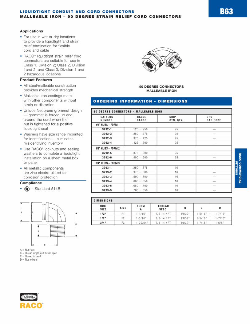
LIQUIDTIGHT CONDUIT AND CORD CONNECTORSMALLEABLE IRON – 90 DEGREE STRAIN RELIEF CORD CONNECTORS
B63
ORDERING INFORMATION - DIMENSIONS
90 DEGREE CONNECTORS MALLEABLE IRON
CATALOG CABLE SH IP UPCNUMBER RANGE CT N . QT Y. BAR CODE
1/2" HUBS – FORM 1
3792-1 .125 - .250 25 —
3792-2 .250 - .375 25 —
3792-3 .375 - .425 25 —
3792-4 .425 - .500 25 —
1/2" HUBS – FORM 2
3792-5 .375 - .500 25 —
3792-6 .500 - .600 25 —
3/4" HUBS – FORM 3
3793-1 .250 - .375 10 —
3793-2 .375 - .500 10 —
3793-3 .500 - .600 10 —
3793-4 .600 - .650 10 —
3793-6 .650 - .700 10 —
3793-5 .700 - .850 10 —
9 0 D E G R E E C O N N E C T O R S - M A L L E A B L E I R O N
A = Nut FlatsB = Thread length and thread spec.C = Thread to bendD = Nut to bend
HUB FORM THREADS IZE S IZE A SPEC . B C D
1/2" F1 1-1/16" 1/2-14 NPT 19/32" 1-5/16" 1-7/16"
1/2" F2 1-3/16" 1/2-14 NPT 19/32" 1-5/16" 1-7/16"
3/4" F3 1-29/64" 3/4-14 NPT 19/32" 1-7/16" 1-5/8"
D I M E N S I O N S
Applications
• For use in wet or dry locations to provide a liquidtight and strainrelief termination for flexible cord and cable
• RACO® liquidtight strain relief cordconnectors are suitable for use inClass 1, Division 2; Class 2, Division1and 2; and Class 3, Division 1 and2 hazardous locations
Product Features
• All steel/malleable constructionprovides mechanical strength
• Malleable iron castings mate with other components withoutstrain or distortion
• Unique Neoprene grommet design— grommet is forced up and around the cord when the nut is tightened for a positive liquidtight seal
• Washers have size range imprinted for identification — eliminatesmisidentifying inventory
• Use RACO® locknuts and sealingwashers to complete a liquidtightinstallation on a sheet metal boxor panel
• All metallic components are zinc electro plated for corrosion protection
Compliance
• – Standard 514B ®
RA
CO
CO
MM
ER
CIA
L
FIT
TIN
GS
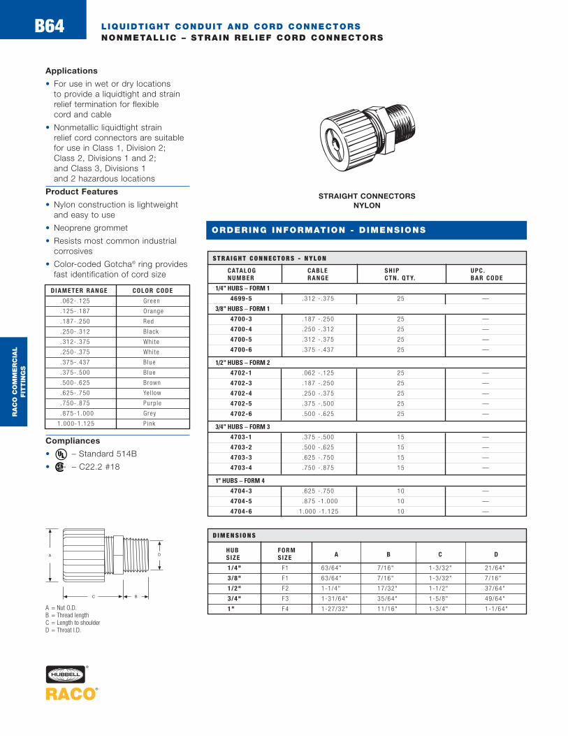
LIQUIDTIGHT CONDUIT AND CORD CONNECTORSNONMETALLIC – STRAIN RELIEF CORD CONNECTORS
B64
Applications
• For use in wet or dry locations to provide a liquidtight and strainrelief termination for flexible cord and cable
• Nonmetallic liquidtight strain relief cord connectors are suitablefor use in Class 1, Division 2; Class 2, Divisions 1 and 2; and Class 3, Divisions 1 and 2 hazardous locations
Product Features
• Nylon construction is lightweightand easy to use
• Neoprene grommet
• Resists most common industrialcorrosives
• Color-coded Gotcha® ring providesfast identification of cord size
Compliances
• – Standard 514B
• – C22.2 #18®
®
STRAIGHT CONNECTORS NYLON
CATALOG CABLE SH IP UPC .NUMBER RANGE CT N . QT Y. BAR CODE
1/4" HUBS – FORM 1
4699-5 .312 - .375 25 —
3/8" HUBS – FORM 1
4700-3 .187 - .250 25 —
4700-4 .250 - .312 25 —
4700-5 .312 - .375 25 —
4700-6 .375 - .437 25 —
1/2" HUBS – FORM 2
4702-1 .062 - .125 25 —
4702-3 .187 - .250 25 —
4702-4 .250 - .375 25 —
4702-5 .375 - .500 25 —
4702-6 .500 - .625 25 —
3/4" HUBS – FORM 3
4703-1 .375 - .500 15 —
4703-2 .500 - .625 15 —
4703-3 .625 - .750 15 —
4703-4 .750 - .875 15 —
1" HUBS – FORM 4
4704-3 .625 - .750 10 —
4704-5 .875 -1 .000 10 —
4704-6 1.000 -1 .125 10 —
S T R A I G H T C O N N E C T O R S - N Y L O N
A = Nut O.D.B = Thread lengthC = Length to shoulderD = Throat I.D.
HUB FORMSIZE S IZE A B C D
1/4" F1 63/64" 7/16" 1-3/32" 21/64"
3/8" F1 63/64" 7/16" 1-3/32" 7/16"
1/2" F2 1-1/4" 17/32" 1-1/2" 37/64"
3/4" F3 1-31/64" 35/64" 1-5/8" 49/64"
1" F4 1-27/32" 11/16" 1-3/4" 1-1/64"
D I M E N S I O N S
DIAME TE R R A N G E COLOR CODE
.062- .125 Green
.125- .187 Orange
.187- .250 Red
.250- .312 B lack
.312- .375 Whi te
.250- .375 Whi te
.375- .437 B lue
.375- .500 B lue
.500- .625 Brown
.625- .750 Ye l l ow
.750- .875 Purp le
.875-1.000 Grey
1 .000-1.125 P ink
ORDERING INFORMATION - DIMENSIONS
RA
CO
CO
MM
ER
CIA
L
FIT
TIN
GS

LIQUIDTIGHT CONDUIT AND CORD CONNECTORSNONMETALLIC – 90 DEGREE STRAIN RELIEF CORD CONNECTORS
B65
ORDERING INFORMATION - DIMENSIONS
90 DEGREE CONNECTORS NYLON
Applications
• For use in wet or dry locations toprovide a liquidtight and strainrelief termination for flexible cordand cable
• Nonmetallic liquidtight strain relief cord connectors are suitablefor use in Class 1, Division 2; Class 2, Divisions 1 and 2; andClass 3, Divisions 1and 2 hazardous locations
Product Features
• Nylon construction is lightweightand easy to use
• Neoprene grommet
• Resists most common industrialcorrosives
• Color-coded Gotcha® ring provides fast identification of cord size
Compliances
• – Standard 514B
• – C22.2 #18®
®
CATALOG CABLE SH IP UPCNUMBER RANGE CT N . QT Y. BAR CODE
1/2" HUBS – FORM 2
4792-4 .250 - .375 25 —
4792-5 .375 - .500 25 —
4792-6 .500 - .625 25 —
3/4" HUBS – FORM 3
4793-1 .375 - .500 15 —
1" HUBS – FORM 4
4794-3 .625 - .750 10 —
4794-4 .750 - .875 10 —
4794-5 .875 -1 .000 10 —
9 0 D E G R E E C O N N E C T O R S - N Y L O N
A = Nut O.D.B = Thread lengthC = Throat I.D.D = Overall lengthE = Height from shoulder to nut
DIAME TE R R A N G E COLOR CODE
.187- .250 Red
.250- .375 Whi te
.375- .500 B lue
.500- .625 Brown
.625- .750 Ye l l ow
.750- .875 Purp le
.875-1.000 Grey
HUB FORMSIZE S IZE A B C D E
1/2" F2 1-1/4" 17/32" 37/64" 2-1/2" 1-13/32"
3/4" F3 1-31/64" 35/64" 49/64" 2-51/64" 1-21/32"
1" F4 1-27/32" 11/16" 1-1/64" 3-19/64" 1-63/64"
D I M E N S I O N S
RA
CO
CO
MM
ER
CIA
L
FIT
TIN
GS
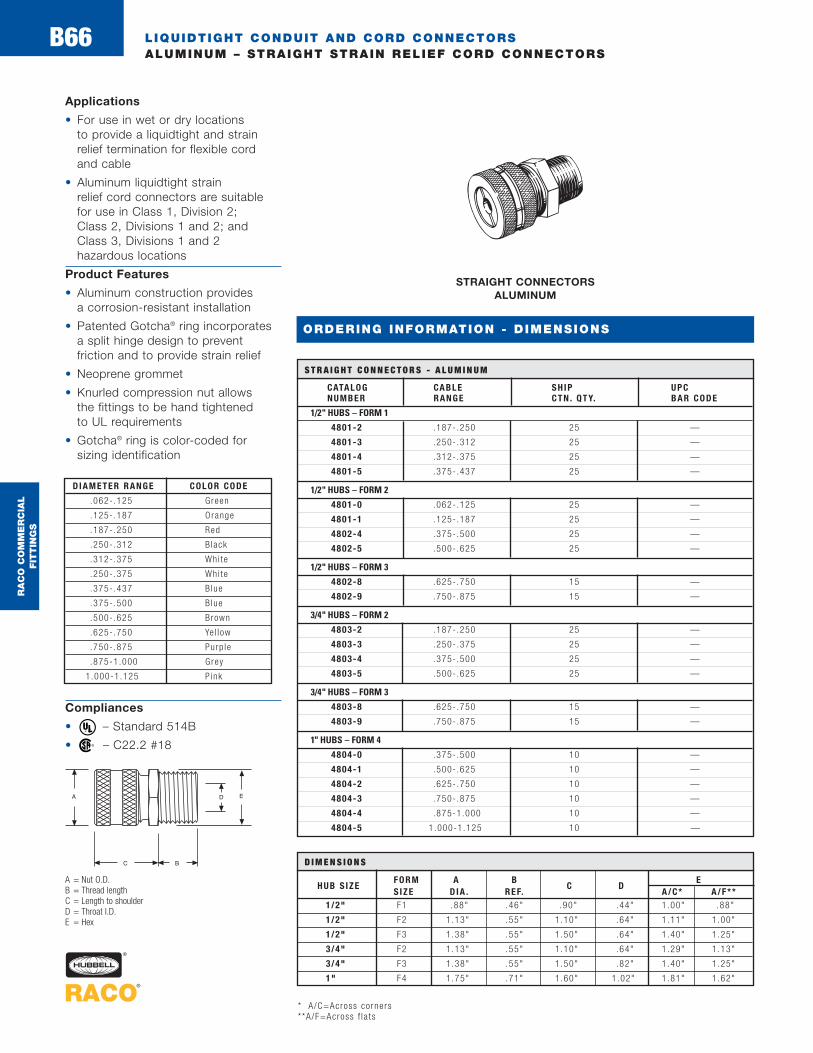
LIQUIDTIGHT CONDUIT AND CORD CONNECTORSALUMINUM – STRAIGHT STRAIN RELIEF CORD CONNECTORS
B66
Applications
• For use in wet or dry locations to provide a liquidtight and strainrelief termination for flexible cord and cable
• Aluminum liquidtight strain relief cord connectors are suitablefor use in Class 1, Division 2; Class 2, Divisions 1 and 2; andClass 3, Divisions 1 and 2 hazardous locations
Product Features
• Aluminum construction provides a corrosion-resistant installation
• Patented Gotcha® ring incorporatesa split hinge design to prevent friction and to provide strain relief
• Neoprene grommet
• Knurled compression nut allows the fittings to be hand tightened to UL requirements
• Gotcha® ring is color-coded for sizing identification
Compliances
• – Standard 514B
• – C22.2 #18®
®
STRAIGHT CONNECTORS ALUMINUM
CATALOG CABLE SH IP UPCNUMBER RANGE CT N . QT Y. BAR CODE
1/2" HUBS – FORM 1
4801-2 .187- .250 25 —
4801-3 .250- .312 25 —
4801-4 .312- .375 25 —
4801-5 .375- .437 25 —
1/2" HUBS – FORM 2
4801-0 .062- .125 25 —
4801-1 .125- .187 25 —
4802-4 .375- .500 25 —
4802-5 .500- .625 25 —
1/2" HUBS – FORM 3
4802-8 .625- .750 15 —
4802-9 .750- .875 15 —
3/4" HUBS – FORM 2
4803-2 .187- .250 25 —
4803-3 .250- .375 25 —
4803-4 .375- .500 25 —
4803-5 .500- .625 25 —
3/4" HUBS – FORM 3
4803-8 .625- .750 15 —
4803-9 .750- .875 15 —
1" HUBS – FORM 4
4804-0 .375- .500 10 —
4804-1 .500- .625 10 —
4804-2 .625- .750 10 —
4804-3 .750- .875 10 —
4804-4 .875-1 .000 10 —
4804-5 1.000-1.125 10 —
S T R A I G H T C O N N E C T O R S - A L U M I N U M
A = Nut O.D.B = Thread lengthC = Length to shoulderD = Throat I.D.E = Hex
FORM A B EHUB S IZE
S IZE D IA . REF.C D
A/C* A/F**1/2" F1 .88" .46" .90" .44" 1.00" .88"
1/2" F2 1.13" .55" 1.10" .64" 1.11" 1.00"
1/2" F3 1.38" .55" 1.50" .64" 1.40" 1.25"
3/4" F2 1.13" .55" 1.10" .64" 1.29" 1.13"
3/4" F3 1.38" .55" 1.50" .82" 1.40" 1.25"
1" F4 1.75" .71" 1.60" 1.02" 1.81" 1.62"
D I M E N S I O N S
DIAME TE R R A N G E COLOR CODE
.062- .125 Green
.125- .187 Orange
.187- .250 Red
.250- .312 B lack
.312- .375 Whi te
.250- .375 Whi te
.375- .437 B lue
.375- .500 B lue
.500- .625 Brown
.625- .750 Ye l l ow
.750- .875 Purp le
.875-1.000 Grey
1.000-1.125 P ink
ORDERING INFORMATION - DIMENSIONS
* A /C=Across co rners**A/F=Across f l a t s
RA
CO
CO
MM
ER
CIA
L
FIT
TIN
GS

FLEXIBLE METAL CONDUIT F ITTINGSMALLEABLE IRON – STRAIGHT SQUEEZE CONNECTORS
B67
ORDERING INFORMATION - DIMENSIONS
Application
• For use in dry locations to bondflexible metal conduit to a box or enclosure
Product Features
• All malleable construction insures mechanical protection for the raceway
• Electro zinc plated for addedcorrosion protection
• UPC bar coded fittings are individually polybagged with a preprinted UPC-A bar code and packaged in pre-scored tear top cartons for an attractive presentation
Compliances
• – Standard 514B®
STRAIGHT - SQUEEZE INSULATED
MALLEABLE IRON
CATALOG UNIT. SH IP. UPCNUMBER TRADE S IZE CTN . QTY. CTN . QTY. BAR CODE
3301 3/ 8"* — 50 —
3302 1/ 2" — 50 —
3302-8 1/ 2" 1 25
3303 3/ 4" — 25 —
3303-8 3/ 4" 1 20
3304 1" — 25 —
3304-8 1" 1 5
3305 1-1/ 4" — 25 —
3306 1-1/ 2" — 25 —
3308 2" — 10 —
3310 2-1/2" — 1 —
3312 3" — 1 —
3314 3-1/2" — 1 —
3316 4" — 1 —
S T R A I G H T - S Q U E E Z E - I N S U L AT E D - M A L L E A B L E I R O N
A = Overall lengthB = Thread length and thread specC = Throat I.D.D = Length to conduit stopE = Clamping rangeF = Maximum width body
TRADES IZE A B THD. SPEC . C D E F
3301 1-3/32" 1/2" 1/2–14 NPS .622" 1/2" 17/32"-5/8" 1-7/32"
3302 1-3/8" 3/8" 1/2–14 NPS .622" 7/8" 13/16"-15/16" 1-17/32"
3302-8 1-3/8" 3/8" 1/2–14 NPS .622" 7/8" 13/16"-15/16" 1-17/32"
3303 1-1/2" 7/16" 3/4–14 NPS .813" 15/16" 1-1/32"-1-1/8" 1-3/4"
3303-8 1-1/2" 7/16" 3/4–14 NPS .813" 15/16" 1-1/32"-1-1/8" 1-3/4"
3304 1-3/4" 5/8" 1–11–1/2 NPT 1.00" 15/16" 1-3/16"-1-3/8" 2"
3304-8 1-3/4" 5/8" 1–11–1/2 NPT 1.00" 15/16" 1-3/16"-1-3/8" 2"
3305 2-1/32" 5/8" 1–1/4–11–1/2 NPT 1.250" 1-1/4" 1-15/32"-1-21/32" 2-1/2"
3306 2-7/32" 21/32" 1–1/2–11–1/2 NPT 1.500" 1-3/8" 1-25/32"-1-31/32" 2-7/8"
3308 2-25/32" 11/16" 2–11–1/2 NPT 2.00" 1-7/8" 2-1/4"-2-15/32" 3-3/8"
D I M E N S I O N S
*For 1 /2" knockou t
COMING
SOON
RA
CO
CO
MM
ER
CIA
L
FIT
TIN
GS

FLEXIBLE METAL CONDUIT F ITTINGSMALLEABLE IRON – STRAIGHT SQUEEZE CONNECTORS
B68
ORDERING INFORMATION - DIMENSIONS
SQUEEZE - STRAIGHT UNINSULATED
MALLEABLE IRON
CATALOG UNIT. SH IP. UPCNUMBER TRADE S IZE CTN . QTY. CTN . QTY. BAR CODE
2101 3/ 8" * — 50 —
2102 1/ 2" — 50 —
2102-8 1/ 2" 1 25
2103 3/ 4" — 25 —
2103-8 3/ 4" 1 20
2104 1" — 25 —
2104-8 1" 1 5
2105 1-1/ 4" — 25 —
2106 1-1/ 2" — 25 —
2108 2" — 10 —
2110 2-1/ 2" — 5 —
2112 3" — 5 —
2114 3-1/2" — 1 —
2116 4" — 1 —
S Q U E E Z E - S T R A I G H T - U N I N S U L AT E D - M A L L E A B L E I R O N
A = Overall lengthB = Thread length and thread specC = Throat I.D.D = Length to conduit stopE = Clamping rangeF = Maximum width body
Application
• For use in dry locations to bond flexible metal conduit to a box or enclosure
Product Features
• All malleable construction insures mechanical protection for the raceway
• Electro zinc plated for addedcorrosion protection
• UPC bar coded fittings are individually polybagged with a preprinted UPC-A bar code and packaged in pre-scored tear top cartons for an attractive presentation
Compliances
• – Standard 514B
• – C22.2 #18®
®
TRADES IZE A B THD. SPEC . C D E F
2101 1-1/16" 1/2" 1/2–14 NPS .622" 1/2" 17/32"-5/8" 1-7/32"
21021-11/32" 3/8" 1/2–14 NPS .622" 7/8" 13/16"-15/16" 1-7/32"2102-8
21031-15/32" 7/16" 3/4–14 NPS .813" 15/16" 1-1/32"-1-1/8" 1-3/4"2103-8
21041-23/32" 5/8" 1–11–1/2 NPT 1.00" 15/16" 1-3/16"-13/8" 2"2104-8
2105 2" 5/8" 1-1/4–11–1/2 NPT 1.250" 1-1/4" 1-15/32"-1-21/32" 2-1/2"
2106 2-3/16" 21/32" 1-1/2–11–1/2 NPT 1.500" 1-3/8" 1-25/32"-1-31/32" 2-7/8"
2108 2-3/4" 11/16" 2–11–1/2 NPT 2.000" 1-7/8" 2-1/4"-2-15/32" 3-3/8"
2110 2-59/64" 57/64" 2-1/2–8 NPS 2.50" 1-3/4" 2-1/2"-3-1/16" 4-1/8"
2112 3-1/32" 29/32" 3–8 NPS 3.00" 1-15/16" 3-3/16"-3-9/16" 4-7/8"
D I M E N S I O N S
*For 1 /2" knockou t
COMING
SOON
RA
CO
CO
MM
ER
CIA
L
FIT
TIN
GS

FLEXIBLE METAL CONDUIT F ITTINGSMALLEABLE IRON – 90 DEGREE SQUEEZE CONNECTORS
B69
ORDERING INFORMATION - DIMENSIONS
Application
• For use in dry locations to bondflexible metal conduit to a box or enclosure
Product Features
• Malleable construction insures mechanical protection for the raceway
• Electro zinc plated for addedcorrosion protection
• UPC bar coded fittings are individually polybagged with a preprinted UPC-A bar code and packaged in pre-scored tear top cartons for an attractive presentation
Insulated Compliances
• – Standard 514B
• – C22.2 #18 (3202-3204-8)
Uninsulated Compliances
• – Standard 514B
• – C22.2 #18 (2202-2204-8)®
®
®
®
SQUEEZE 90 DEGREE - INSULATED
MALLEABLE IRON
A = Overall lengthB = Thread length and thread specC = Throat I.D.D = Length to conduit stopE = Clamping rangeF = Maximum width body
INSULATED UNINSULATEDIRON IRON TRADE UNIT SH IP UPCCATALOG CATALOG S IZE CTN . QTY. CTN . QTY. BAR CODENUMBER NUMBER
3201 2201 3/ 8" * — 50 —
3202 — 1/ 2" — 25 —
— 2202 1/ 2" 25 100 —
3202-8 2202-8 1/ 2" 1 25
3203 2203 3/ 4" — 25 —
3203-8 2203-8 3/ 4" 1 20
3204 2204 1" — 25 —
3204-8 2204-8 1" 1 5
3205 2205 1-1/ 4" — 10 —
3206 2206 1-1/ 2" — 5 —
3208 2208 2" — 5 —
3210 2210 2-1/ 2" — 1 —
3212 2212 3" — 1 —
3214 2214 3-1/2" — 1 —
3216 2216 4" — 1 —
S Q U E E Z E 9 0 D E G R E E – I N S U L AT E D A N D U N I N S U L AT E D – M A L L E A B L E I R O N
Coming Soon* For 1 /2" knockou t
INSULATED UNINSULATEDI R O N I R O N T H D.CATALOG CATALOG A B SPEC . C D E F
NUMBER NUMBER
3201 2201 2 9/16" 1/2–14 NPT .622" 3/4" 7/16"-5/8" 1-3/8"
3202 2202 2 9/16" 1/2–14 NPT .622" 7/8" 23/32"-15/16" 2"
3202-8 2202-8 2 9/16" 1/2–14 NPT .622" 7/8" 23/32"-15/16" 2"
3203 2203 2-1/8" 1/2" 3/4–14 NPS .822" 1" 7/8"-1-1/8" 2-3/16"
3203-8 2203-8 2-1/8" 1/2" 3/4–14 NPS .822" 1" 7/8"-1-1/8" 2-3/16"
3204 2204 2-7/8" 5/8" 1–11-1/2 NPT 1.045" 1" 1-7/32"-1-3/8" 2-3/8"
3204-8 2204-8 2-7/8" 5/8" 1–11-1/2 NPT 1.045" 1" 1-7/32"-1-3/8" 2-3/8"
3205 2205 4-7/8" 5/8"1-1/4–
1.375" 1-1/16" 1-7/16"-1-5/8" 2-3/4"11-1/2 NPT
3206 2206 5-1/16" 5/8"1-1/2–
1.610" 1-5/8"1-21/32"-
3-1/8"11-1/2 NPT 1-31/32"
3208 2208 6-1/2" 21/32" 2–11-1/2 NPT 2.065" 1-7/8" 2-1/8"-2-15/32" 3-5/8"
— 2210 7-5/8" 15/16" 2-1/2–8 NPS 2.500" 2-1/4" 2-13/16"-31/16" 4-3/8"
— 2212 8-13/16" 1-1/32” 3–8 NPS 3.050" 2-1/2" 3-1/16"-3-9/16" 5"
D I M E N S I O N S
SQUEEZE 90 DEGREE - UNINSULATED
MALLEABLE IRON
CS
CS
CS
CS
CS
CS
CS
RA
CO
CO
MM
ER
CIA
L
FIT
TIN
GS
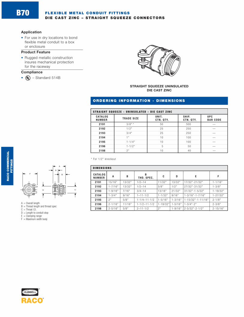
FLEXIBLE METAL CONDUIT F ITTINGSDIE CAST ZINC – STRAIGHT SQUEEZE CONNECTORS
ORDERING INFORMATION - DIMENSIONS
Application
• For use in dry locations to bondflexible metal conduit to a box or enclosure
Product Feature
• Rugged metallic constructioninsures mechanical protection for the raceway
Compliance
• – Standard 514B ®
S T R A I G H T S Q U E E Z E - U N I N S U L AT E D - D I E C A S T Z I N C
A = Overall lengthB = Thread length and thread specC = Throat I.D.D = Length to conduit stopE = Clamping rangeF = Maximum width body
STRAIGHT SQUEEZE UNINSULATED DIE CAST ZINC
* Fo r 1 /2" knockou t
CATALOG UNIT. SH IP. UPCNUMBER TRADE S IZE CTN . QTY. CTN . QTY. BAR CODE
2191 3/ 8" * 50 500 —
2192 1/ 2" 25 250 —
2193 3/ 4" 25 250 —
2194 1" 10 100 —
2195 1-1/ 4" 10 100 —
2196 1-1/ 2" 5 50 —
2198 2" 10 40 —
CATALOG BNUMBER A B THD. SPEC . C D E F
2191 15/16" 13/32" 1/2–14 11/32" 13/32" 17/32"-21/32" 1-1/16"
2192 1-7/16" 13/32" 1/2–14 5/8" 1/2" 27/32"-31/32" 1-3/8"
2193 1-9/16" 7/16" 3/4–14 13/16" 21/32" 31/32"-1-5/32" 1-19/32"
2194 1-3/4" 9/16" 1–11-1/2 1-1/32" 9/16" 1-3/16"-1-7/16" 1-27/32"
2195 2" 5/8" 1-1/4–11-1/2 1-5/16" 1-3/16" 1-15/32"-1-11/16" 2-1/8"
2196 2-1/16" 11/16" 1-1/2–11-1/2 1-19/32" 1-5/16" 1-3/4"-2" 2-3/8"
2198 2-5/16" 5/8" 2–11-1/2 2" 1-9/16" 2-5/32"-2-1/2" 2-15/16"
D I M E N S I O N S
RA
CO
CO
MM
ER
CIA
L
FIT
TIN
GS
B70

FLEXIBLE METAL CONDUIT F ITTINGSDIE CAST ZINC – 45 AND 90 DEGREE SQUEEZE CONNECTORS
Application
• For use in dry locations to bondflexible metal conduit to a box or enclosure
Product Feature
• Rugged metallic constructioninsures mechanical protection for the raceway
Compliances
• – Standard 514B
• – C22.2 #18
(2221 not UL Listed or CSA Certified)
®
®
45 DEGREE SQUEEZE UNINSULATED DIE CAST ZINC
90 DEGREE SQUEEZE UNINSULATEDDIE CAST ZINC
CATALOG UNIT. SH IP. UPCNUMBER TRADE S IZE CTN . QTY. CTN . QTY. BAR CODE
2221* 3/ 8" ** — 25 —
2222 1/ 2" — 25 —
4 5 D E G R E E S Q U E E Z E - U N I N S U L AT E D - M A L L E A B L E I R O N - D I E C A S T Z I N C
CATALOG UNIT. SH IP. UPCNUMBER TRADE S IZE CTN . QTY. CTN . QTY. BAR CODE
2691 3/ 8" * 50 500 —
2692 1/ 2" 25 250 —
2693 3/ 4" 10 100 —
2694 1" 5 50 —
2695 1-1/ 4" 10 40 —
2696 1-1/ 2" — 5 —
2698 2" — 5 —
9 0 D E G R E E S Q U E E Z E - U N I N S U L AT E D - D I E C A S T Z I N C
A = Length to end of fittingB = Length to bendC = Thread length and thread specD = Clamping rangeE = Maximum width body
A = Overall lengthB = Thread length and thread specC = Throat I.D.D = Length to conduit stopE = Clamping rangeF = Maximum width body
CATALOGNUMBER A B C THD. SPEC . D E
2221 5/8" 1-3/16" 1/2" 1/2–14 7/16"-5/8" 1-3/8"
2222 1-3/16" 2" 1/2" 1/2–14 25/32"-29/32" 1-3/8"
D I M E N S I O N S
CATALOGNUMBER A B THD. SPEC . C D E F
2691 1-7/8" 3/8" 1/2–14 19/32" 13/16" 13/32"-9/16" 1-5/16"
2692 2-9/32" 11/32" 1/2–14 5/8" 1-1/32" 21/32"-15/16" 1-21/32"
2693 2-7/16" 15/32" 3/4–14 25/32" 1-1/8" 25/32"-1-1/8" 1-29/32"
2694 2-15/16" 9/16" 1–11-1/2 1-1/32" 1" 1-3/32"-1-1/2" 2-3/8"
2695 4" 5/8" 1-1/4–11-1/2 1-3/8" 1-1/8" 1-5/16"-1-3/4" 2-11/16"
2696 6-1/4" 3/4" 1-1/2–11-1/2 1-7/16" 1-13/16" 1-9/16"-2-1/4" 3-5/8"
2698 6-1/4" 3/4" 2–11-1/2 1-31/32" 1-13/16" 1-19/32"-2-1/4" 3-9/16"
D I M E N S I O N S
* No t UL L i s ted o r CSA Cer t i f i ed
** Fo r 1 /2" knockou t
* Fo r 1 /2" knockou t
ORDERING INFORMATION - DIMENSIONS
RA
CO
CO
MM
ER
CIA
L
FIT
TIN
GS
B71
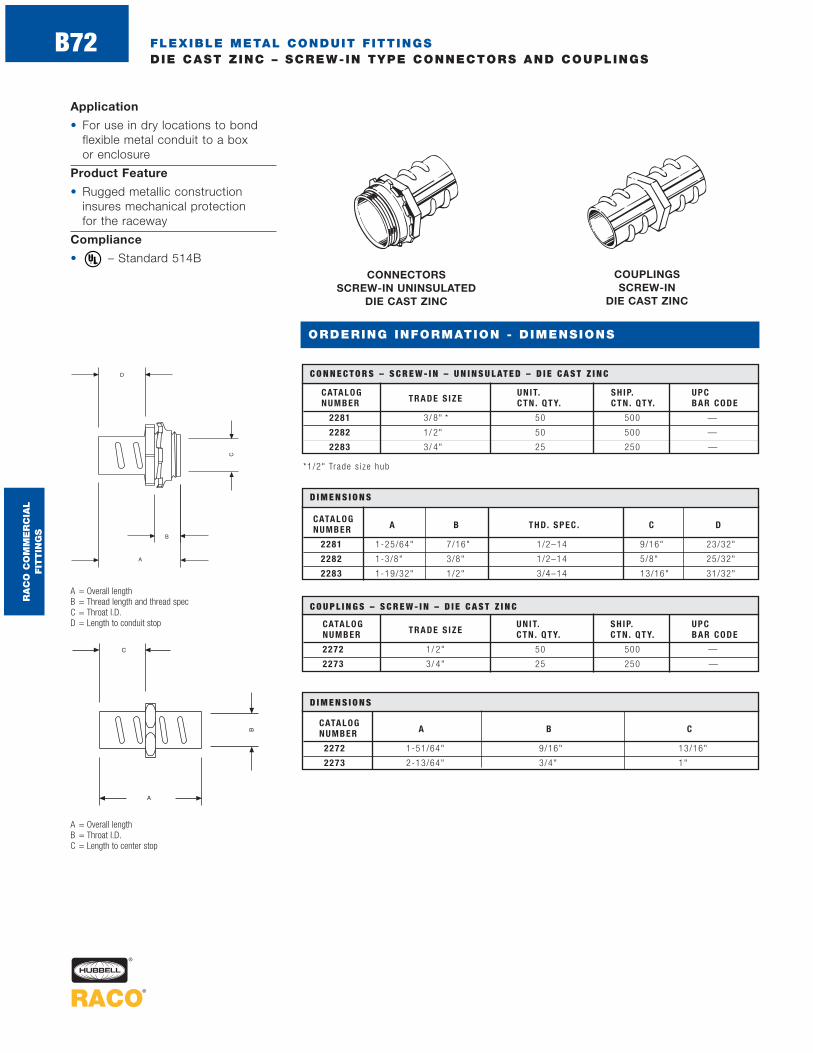
FLEXIBLE METAL CONDUIT F ITTINGSDIE CAST ZINC – SCREW-IN TYPE CONNECTORS AND COUPLINGS
Application
• For use in dry locations to bondflexible metal conduit to a box or enclosure
Product Feature
• Rugged metallic constructioninsures mechanical protection for the raceway
Compliance
• – Standard 514B ®
CONNECTORSSCREW-IN UNINSULATED
DIE CAST ZINC
COUPLINGS SCREW-IN
DIE CAST ZINC
CATALOG UNIT. SH IP. UPCNUMBER TRADE S IZE CTN . QTY. CTN . QTY. BAR CODE
2281 3/ 8" * 50 500 —
2282 1/ 2" 50 500 —
2283 3/ 4" 25 250 —
C O N N E C T O R S – S C R E W - I N – U N I N S U L AT E D – D I E C A S T Z I N C
CATALOG UNIT. SH IP. UPCNUMBER TRADE S IZE CTN . QTY. CTN . QTY. BAR CODE
2272 1/ 2" 50 500 —
2273 3/ 4" 25 250 —
C O U P L I N G S – S C R E W - I N – D I E C A S T Z I N C
A = Overall lengthB = Thread length and thread specC = Throat I.D.D = Length to conduit stop
A = Overall lengthB = Throat I.D.C = Length to center stop
CATALOGNUMBER A B THD. SPEC . C D
2281 1-25/64" 7/16" 1/2–14 9/16" 23/32"
2282 1-3/8" 3/8" 1/2–14 5/8" 25/32"
2283 1-19/32" 1/2" 3/4–14 13/16" 31/32"
D I M E N S I O N S
CATALOGNUMBER A B C
2272 1-51/64" 9/16" 13/16"
2273 2-13/64" 3/4" 1"
D I M E N S I O N S
ORDERING INFORMATION - DIMENSIONS
RA
CO
CO
MM
ER
CIA
L
FIT
TIN
GS
B72
*1/2" Trade s i ze hub
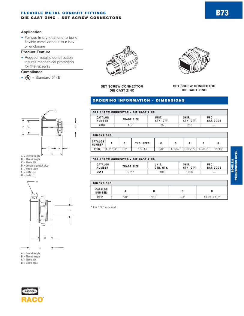
FLEXIBLE METAL CONDUIT F ITTINGSDIE CAST ZINC – SET SCREW CONNECTORS
SET SCREW CONNECTOR DIE CAST ZINC
SET SCREW CONNECTOR DIE CAST ZINC
CATALOG UNIT. SH IP. UPCNUMBER TRADE S IZE CTN . QTY. CTN . QTY. BAR CODE
2632 1/ 2" 25 250 —
S E T S C R E W C O N N E C T O R - D I E C A S T Z I N C
CATALOG UNIT. SH IP. UPCNUMBER TRADE S IZE CTN . QTY. CTN . QTY. BAR CODE
2511 3/ 8" * 100 1000 —
S E T S C R E W C O N N E C T O R - D I E C A S T Z I N CA = Overall lengthB = Thread lengthC = Throat I.D.D = Length to conduit stopE = Screw specF = Body O.D.G = Body I.D.
A = Overall lengthB = Thread lengthC = Throat I.D.D = Screw spec
CATALOGNUMBER A B THD. SPEC . C D E F G
2632 1-31/64" 3/8" 1/2-14 5/8" 1-1/32" 8-32x1/2" 1-5/32" 15/16"
D I M E N S I O N S
CATALOGNUMBER A B C D
2511 7/8" 7/16" 3/8" 10-24 x 1 /2"
D I M E N S I O N S
* Fo r 1 /2" knockou t
ORDERING INFORMATION - DIMENSIONS
Application
• For use in dry locations to bondflexible metal conduit to a box or enclosure
Product Feature
• Rugged metallic constructioninsures mechanical protection for the raceway
Compliance
• – Standard 514B ®
RA
CO
CO
MM
ER
CIA
L
FIT
TIN
GS
B73

Application
• For use in dry locations to bondflexible metal conduit to a box or enclosure
Product Feature
• Rugged metallic constructioninsures mechanical protection for the raceway
Compliance
• – Standard 514B ®
CLAMP TYPE DIE CAST ZINC
DUPLEX DIE CAST ZINC
CATALOG UNIT. SH IP. UPCNUMBER TRADE S IZE CTN . QTY. CTN . QTY. BAR CODE
2661 3/ 8" * 100 1000 —
C L A M P T Y P E - D I E C A S T Z I N C
CATALOG UNIT. SH IP. UPCNUMBER TRADE S IZE CTN . QTY. CTN . QTY. BAR CODE
2611 3/ 8" * 25 250 —
D U P L E X - D I E C A S T Z I N C
A = Overall lengthB = Thread lengthC = Throat I.D.D = Clamping rangeE = Maximum body width
A = Overall lengthB = WidthC = Thread lengthD = Clamping range
FLEXIBLE METAL CONDUIT F ITTINGSDIE CAST ZINC – CLAMP TYPE CONNECTORS AND DUPLEX CONNECTORS
* Fo r 1 /2" knockou t
* Fo r 1 /2" knockou t
CATALOGNUMBER A B C D
2611 1-9/16" 1-21/32" 7/16" 1/8"-9/16"
D I M E N S I O N S
CATALOG THD.NUMBER A B SPEC . C D E
2661 27/32" 3/8" 1/2-14 3/8" 5/32"-5/8" 1-3/16"
D I M E N S I O N S
ORDERING INFORMATION - DIMENSIONS
RA
CO
CO
MM
ER
CIA
L
FIT
TIN
GS
B74

FLEXIBLE METAL CONDUIT F ITTINGSMALLEABLE IRON – COMBINATION COUPLINGS
Applications
• For use when coupling flexiblemetal conduit to rigid/IMC conduit
• Use RACO® Cat. Nos. 1552-1554when coupling threaded rigid/IMCconduit to flexible metal conduit
Product Features• Rugged metallic construction
insures mechanical protection
• Steel/malleable components are electro zinc plated for added corrosion protection
Compliance• – Standard 514B
®
FLEX - RIGID COUPLINGS MALLEABLE IRON
CATALOG UNIT. SH IP. UPCNUMBER TRADE S IZE CTN . QTY. CTN . QTY. BAR CODE
1552 1/ 2" 25 100 —
1553 3/ 4" — 25 —
1554 1" — 25 —
F L E X - R I G I D C O U P L I N G S - M A L L E A B L E I R O N
A = Width across flex sideB = Hub O.D.C = Hub I.D.D = Thread spec hubE = Overall length
CATALOG DNUMBER A B C THD. SPEC . E
1552 1-5/8" 1-1/32" 3/4" 1/2-14 NPT 1-21/32"
1553 1-7/8" 1-7/32" 31/32" 3/4-14 NPT 1-25/32"
1554 2-3/16" 1-1/2" 1-7/32" 1-11-1/2 NPT 1-13/16"
D I M E N S I O N S
ORDERING INFORMATION - DIMENSIONS
RA
CO
CO
MM
ER
CIA
L
FIT
TIN
GS
B75
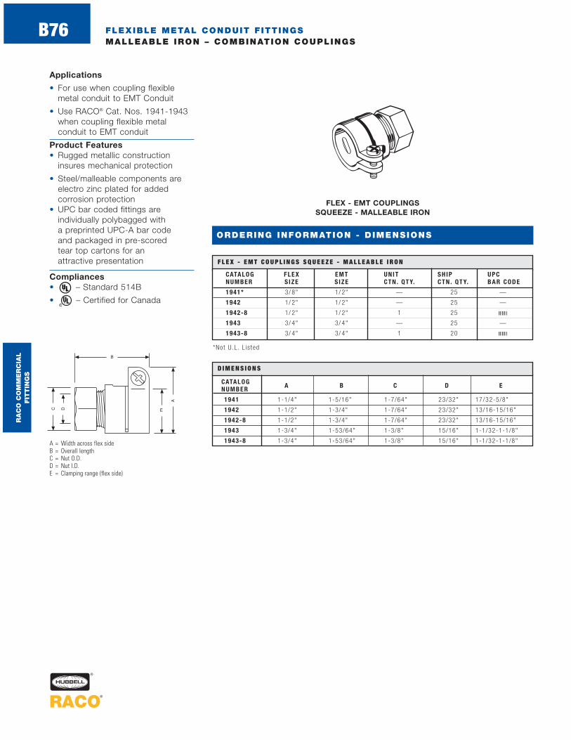
ORDERING INFORMATION - DIMENSIONS
FLEXIBLE METAL CONDUIT F ITTINGSMALLEABLE IRON – COMBINATION COUPLINGS
Applications
• For use when coupling flexiblemetal conduit to EMT Conduit
• Use RACO® Cat. Nos. 1941-1943when coupling flexible metal conduit to EMT conduit
Product Features• Rugged metallic construction
insures mechanical protection
• Steel/malleable components are electro zinc plated for added corrosion protection
• UPC bar coded fittings are individually polybagged with a preprinted UPC-A bar code and packaged in pre-scored tear top cartons for an attractive presentation
Compliances• – Standard 514B
• – Certified for Canada®
FLEX - EMT COUPLINGS SQUEEZE - MALLEABLE IRON
CATALOG FLEX EMT UNIT SH IP UPCNUMBER S IZE S IZE CTN . QTY. CTN . QTY. BAR CODE
1941* 3/ 8" 1/ 2" — 25 —
1942 1/ 2" 1/ 2" — 25 —
1942-8 1/ 2" 1/ 2" 1 25
1943 3/ 4" 3/ 4" — 25 —
1943-8 3/ 4" 3/ 4" 1 20
F L E X - E M T C O U P L I N G S S Q U E E Z E - M A L L E A B L E I R O N
A = Width across flex sideB = Overall lengthC = Nut O.D.D = Nut I.D.E = Clamping range (flex side)
CATALOGNUMBER A B C D E
1941 1-1/4" 1-5/16" 1-7/64" 23/32" 17/32-5/8"
1942 1-1/2" 1-3/4" 1-7/64" 23/32" 13/16-15/16"
1942-8 1-1/2" 1-3/4" 1-7/64" 23/32" 13/16-15/16"
1943 1-3/4" 1-53/64" 1-3/8" 15/16" 1-1/32-1-1/8"
1943-8 1-3/4" 1-53/64" 1-3/8" 15/16" 1-1/32-1-1/8"
D I M E N S I O N S
RA
CO
CO
MM
ER
CIA
L
FIT
TIN
GS
B76
*No t U .L . L i s ted
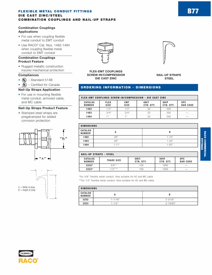
FLEXIBLE METAL CONDUIT F ITTINGSDIE CAST ZINC/STEELCOMBINATION COUPLINGS AND NAIL-UP STRAPS
ORDERING INFORMATION - DIMENSIONS
FLEX-EMT COUPLINGS SCREW-IN/COMPRESSION
DIE CAST ZINCNAIL-UP STRAPS
STEEL
CATALOG FLEX EMT UNIT SH IP UPCNUMBER S IZE S IZE CTN . QTY. CTN . QTY. BAR CODE
1482 1/ 2" 1/ 2" 50 500 —
148 3 3/ 4" 3/ 4" 25 250 —
148 4 1" 1" 25 250 —
F L E X - E M T C O U P L I N G S S C R E W - I N / C O M P R E S S I O N - D I E C A S T Z I N C
CATALOG UNIT. SH IP. UPCNUMBER TRADE S IZE CTN . QTY. CTN . QTY. BAR CODE
2252* 3/ 8" * 100 1000 —
225 3 * 1/ 2" ** 100 1000 —
N A I L - U P S T R A P S - S T E E L
Combination CouplingsApplications
• For use when coupling flexiblemetal conduit to EMT conduit
• Use RACO® Cat. Nos. 1482-1484when coupling flexible metal conduit to EMT conduit
Combination Couplings Product Feature
• Rugged metallic construction insures mechanical protection
Compliances
• – Standard 514B
• – Certified for Canada
Nail-Up Straps Application
• For use in mounting flexible metal conduit, armored cable, and MC cable
Nail-Up Straps Product Feature
• Stamped steel straps are pregalvanized for added corrosion protection
®
D I M E N S I O N S
CATALOGNUMBER A B
1482 .84" 1 .10"
1483 .95" 1 .30"
1484 1.11" 1.62"
*For 3 /8" f l ex ib le meta l condu i t . A l so su i tab le fo r AC and MC cab le
**For 1 /2" f l ex ib le meta l condu i t . A l so su i tab le fo r AC and MC cab le
D I M E N S I O N S
CATALOGNUMBER A B
2252 1-1/16" 2-3/16"
2253 1-1/4" 2-19/64"
A = Width of strapB = Height of strap
RA
CO
CO
MM
ER
CIA
L
FIT
TIN
GS
B77

ARMORED CABLE CONNECTORSMALLEABLE IRON/ZINC DIE CAST – CONNECTORS
Application
• For use in dry locations to bondarmored cable to a box or enclosure
Product Feature
• Rugged metallic constructioninsures mechanical protection for the raceway
Compliance
• – Standard 514B®
SET SCREW DIE CAST ZINC
SET SCREW MALLEABLE IRON
CATALOG UNIT SH IP UPCNUMBER CT N . QT Y. CT N . QT Y. BAR CODE
2181 — 50 —
S E T S C R E W - M A L L E A B L E I R O N
CATALOG UNIT SH IP UPCNUMBER CT N . QT Y. CT N . QT Y. BAR CODE
2511 100 1000 —
S E T S C R E W - D I E C A S T Z I N C
A = Overall lengthB = Thread lengthC = Throat I.D.D = Screw spec
A = Overall lengthB = Thread lengthC = Throat I.D.D = Screw spec
CATALOGNUMBER A B C D
2181 1-1/16" 19/32" 11/32" Fil l ister Head 10-24 x 1/2"
D I M E N S I O N S
CATALOGNUMBER A B C D
2511 7/8" 7/16" 3/8" 10-24 x 1 /2"
D I M E N S I O N S
1/2" Hub s i ze su i tab le fo r use w i th s tee l a rmored cab le 14-2 ( .450 ) to 10-2
1/2" Hub s i ze su i tab le fo r use w i th s tee l a rmored cab le s i zes 2#14, 3#14, 2#12, 3#12, 2#10,
and 3#10 a l l w i th ground w i re
ORDERING INFORMATION - DIMENSIONS
RA
CO
CO
MM
ER
CIA
L
FIT
TIN
GS
B78

ARMORED CABLE CONNECTORSZINC DIE CAST – CONNECTORS
CLAMP TYPE DIE CAST ZINC
CATALOG UNIT. SH IP. UPCNUMBER TRADE S IZE CTN . QTY. CTN . QTY. BAR CODE
2661 — 100 1000 —
C L A M P T Y P E - D I E C A S T Z I N C
CATALOG UNIT. SH IP. UPCNUMBER TRADE S IZE CTN . QTY. CTN . QTY. BAR CODE
2191 3/8"* 50 500 —
2192 1/ 2" 25 250 —
2193 3/ 4" 25 250 —
2194 1" 10 100 —
S Q U E E Z E T Y P E - U N I N S U L AT E D - D I E C A S T Z I N C
A = Overall lengthB = Thread length and thread specC = Throat I.D.D = Length to conduit stopE = Clamping rangeF = Maximum width body
A = Overall lengthB = Thread lengthC = Throat I.D.D = Clamping rangeE = Maximum body width
Application
• For use in dry locations to bond armored cable to a box or enclosure
Product Feature
• Rugged metallic constructioninsures mechanical protection for the raceway
Compliance
• – Standard 514B ®
CATALOG THD.NUMBER A B SPEC . C D E
2661 27/32" 3/8" 1/2-14 3/8" 5/32"-5/8" 1-3/16"
D I M E N S I O N S
For 1 /2" knockou t . Su i tab le fo r use w i th s tee l a rmored cab le s i zes 2#14, 3#14, 2#12, 3#12, 2#10, and
3#10 a l l w i th ground w i re
CATALOGNUMBER A B THD. SPEC . C D E F
2191 15/16" 13/32" 1/2–14 11/32" 13/32" 17/32"-21/32" 1-1/16"
2192 1-7/16" 13/32" 1/2–14 5/8" 1/2" 27/32"-31/32" 1-3/8"
2193 1-9/16" 7/16" 3/4–14 13/16" 21/32" 31/32"-15/32" 1-19/32"
2194 1-3/4" 9/16" 1–11-1/2 1-1/32" 9/16" 1-3/16"-1-7/16" 1-27/32"
D I M E N S I O N S
* Fo r 1 /2" knockou t . Su i tab le fo r s tee l a rmored cab le and f l ex ib le meta l condu i t
ORDERING INFORMATION - DIMENSIONS
45 DEGREE SQUEEZE UNINSULATED DIE CAST ZINC
CATALOG UNIT. SH IP. UPCNUMBER TRADE S IZE CTN . QTY. CTN . QTY. BAR CODE
2222 1/ 2" — 25 —
4 5 D E G R E E S Q U E E Z E - U N I N S U L AT E D - D I E C A S T Z I N C
A = Length to end of fittingB = Length to bendC = Thread length and thread specD = Clamping rangeE = Maximum width body
CATALOG THD.NUMBER A B SPEC . C D E
2222 13/16" 2" 1/2" 1/2–14 25/32"-29/32" 1-3/8"
D I M E N S I O N S
SQUEEZE TYPE UNINSULATED DIE CAST ZINC
RA
CO
CO
MM
ER
CIA
L
FIT
TIN
GS
B79

ARMORED CABLE CONNECTORSMALLEABLE IRON – 90 DEGREE CONNECTORS
90 DEGREE SQUEEZE UNINSULATED
MALLEABLE IRON
90 DEGREE SQUEEZE INSULATED THROAT
MALLEABLE IRON
CATALOG UNIT. SH IP. UPCNUMBER TRADE S IZE CTN . QTY. CTN . QTY. BAR CODE
3201 3/ 8" * — 50 —
3202 1/ 2" — 25 —
3202-8 1/ 2" 1 25
3203 3/ 4" — 25 —
3203-8 3/ 4" 1 20
9 0 D E G R E E S Q U E E Z E - I N S U L AT E D T H R O AT - M A L L E A B L E I R O N
CATALOG UNIT. SH IP. UPCNUMBER TRADE S IZE CTN . QTY. CTN . QTY. BAR CODE
2201 3/ 8" * — 50 —
2202 1/ 2" 25 100 —
2202-8 1/ 2" 1 25
2203 3/ 4" — 50 —
2203-8 3/ 4" 1 20
9 0 D E G R E E S Q U E E Z E - U N I N S U L AT E D - M A L L E A B L E I R O N
A = Overall lengthB = Thread length and thread specC = Throat I.D.D = Length to conduit stopE = Clamping rangeF = Maximum width body
Application
• For use in dry locations to bond armored cable to a box or enclosure
Product Features
• Rugged metallic constructioninsures mechanical protection for the raceway
• UPC bar coded fittings are individually polybagged with a preprinted UPC-A bar code and packaged in pre-scored tear top cartons for an attractive presentation
Compliance
• – Standard 514B®
* Fo r 1 /2" knockou t
* Fo r 1 /2" knockou t
CATALOGNUMBER A B THD. SPEC . C D E F
3201, 2201 2 9/16" 1/2–14 NPT .622" 3/4" 7/16"-5/8" 1-3/8"
3202, 2202 2 9/16" 1/2–14 NPT .622" 7/8" 23/32"-15/16" 2"
3202-8, 2202-8 2 9/16" 1/2–14 NPT .622" 7/8" 23/32"-15/16" 2"
3203, 2203 2-1/8" 1/2" 3/4–14 NPS .822" 1" 7/8"-1-1/8" 2-3/16"
3203-8, 2203-8 2-1/8" 1/2" 3/4–14 NPS .822" 1" 7/8"-1-1/8" 2-3/16"
D I M E N S I O N S
ORDERING INFORMATION - DIMENSIONS
RA
CO
CO
MM
ER
CIA
L
FIT
TIN
GS
B80

ARMORED CABLE CONNECTORSDIE CAST ZINC – 90 DEGREE AND DUPLEX CONNECTORS
Application
• For use in dry locations to bond armored cable to a box or enclosure
Product Feature
• Rugged metallic constructioninsures mechanical protection for the raceway
Compliance• – Standard 514B
®
DUPLEX DIE CAST ZINC
90 DEGREE SQUEEZEUNINSULATEDDIE CAST ZINC
CATALOG UNIT. SH IP. UPCNUMBER TRADE S IZE CTN . QTY. CTN . QTY. BAR CODE
2691 3/ 8" * 50 500 —
2692 1/ 2" 25 250 —
2693 3/ 4" 10 100 —
9 0 D E G R E E S Q U E E Z E - U N I N S U L AT E D - D I E C A S T Z I N C
CATALOG UNIT. SH IP. UPCNUMBER TRADE S IZE CTN . QTY. CTN . QTY. BAR CODE
2611 3/ 8" * 25 250 —
D U P L E X - D I E C A S T Z I N C
A = Overall lengthB = Thread length and thread specC = Throat I.D.D = Length to conduit stopE = Clamping rangeF = Maximum width body
A = Overall lengthB = WidthC = Thread lengthD = Clamping range
CATALOGNUMBER A B C D
2611 1-9/16" 1-21/32" 7/16" 1/8"-9/16"
D I M E N S I O N S
* Fo r 1 /2" knockou t
*For 1 /2" knockou t
CATALOG BNUMBER A B THD. SPEC . C D E F
2691 1-7/8" 3/8" 1/2–14 19/32" 13/16" 13/32"-9/16" 1-5/16"
2692 2-9/32" 11/32" 1/2–14 5/8" 1-1/32" 21/32"-15/16" 1-21/32"
2693 2-7/16" 15/32" 3/4–14 25/32" 1-1/8" 25/32"-1-1/8" 1-29/32"
D I M E N S I O N S
ORDERING INFORMATION - DIMENSIONS
RA
CO
CO
MM
ER
CIA
L
FIT
TIN
GS
B81

ORDERING INFORMATION - DIMENSIONS
METAL CLAD CABLE CONNECTORSSTEEL – REDI-LOC ®R CONNECTORS
Application
• For use in dry locations to connect MCI, AC and HCF cable to a boxor enclosure
Product Features
• Patented snap-in design — MCI,AC and HCF Cable can be secure-ly installed in outlet boxes orenclosures in seconds, withouttools or locknuts
• Redi-Loc® R Connectors cut installation time by 33% over competing termination methods
• Compact single unit design — no need to worry about loosecomponents or fumbling with protruding hardware
• Snaps tightly into the knockout —no need to worry about a loose connection
• Reusable design — installation canbe reversed just as easily as it wasoriginally installed
• Integral red insuliner — providesfor maximum wire protection and liner visibility for inspectingauthorities
• Durable all steel construction
• Zinc electroplated — for corrosion protection
• Tri-lingual (English, Spanish and French) installation instructions included in each unit carton
• UPC bar coded fittings are individually polybagged with a preprinted UPC-A bar code and packaged in pre-scored tear top cartons for an attractive presentation
Compliances
• – Standard 514B
• – C22.2 #18
Reference Data
• REDI-LOC® R connectors (2700,2700AJ and 2701) U.S. Patent5,731,543
®
®
REDI-LOC®R CONNECTORSCONNECTORS FOR MCI, AC
AND HCF CABLES STEEL
CATALOG TRADE CABLE UNIT SH IP UPCNUMBER S IZE S IZE CT N . QT Y. CT N . QT Y. BAR CODE
MCI Cab le : .434"- .530" A lum. or.430"- .530" S tee l
2700 1/ 2" Armored Cab le (AC ) : 50 500 —
14/2 ( .430 ) to 12/3 A lum. & S tee l
2700-8 1/ 2" Same in fo . as above 1 25
MCI Cab le : .475"- .575" A lum. &2700AJ 1/ 2" Stee l . A rmored Cab le (AC ) : 50 500 —
14-2 ( .475 ) to 12-4 A lum. & S tee l
MCI Cab le : .590"- .680" A lum. or
2701 3/4".565"- .659" S tee l
25 250 —Armored Cab le (AC ) :10/3 ( .590" ) to 8 /3 A lum. & S tee l
2701-8 3/ 4" Same in fo . as above 1 20
R E D I - L O C ® R C O N N E C T O R S - C O N N E C T O R S F O R M C I , A C A N D H C F C A B L E S S T E E L
A = Overall lengthB = Body widthC = Throat I.D.
CATALOGNUMBER A B C
2700, 2700AJ 1.070" .700" .375"
2700-8 1.070" .700" .375"
2701 1.070" .888" .500"
2701-8 1.070" .888" .500"
D I M E N S I O N S
2700 , 2700-8 2700AJ 2701 , 2701-8CABLE T YPE 1 /2 " KO 1 /2 " KO 3/4" KO
AC S tee l14/2 , 14/3 , 14/4 , 12/2
14/2 , 14/3 , 14/4 , 14/5 12/5 , 10/2 , 10/3 , 10/412/3
HCF S tee l Hea l th Care Fac i l i t i es 14/2 , 14/3 , 12/2 , 12/3 14/2 , 14/3 , 12/2 , 12/312/3 , 12/5 , 10/2 ,10/3 , 10/4 w/Gr ind
AC A luminum14/2 , 14/3 , 14/4 , 12/2 14/2 , 14/3 , 14/4 , 14/5
12/5 , 10/2 , 10/3 , 10/412/3 12/2 , 12/3 , 10/2
MCI S tee l (MCI Cab les inc lude 14/2 , 14/3 , 12/2
14/3 , 14/4 , 12/2 , 12/3 12/4 , 12/5 , 12/6 , 10/2an add ’ l g round w i re ) 10/2 10/3
MCI A luminum (MCI Cab les 14/2 , 14/3 , 12/2
14/3 , 14/4 , 12/2 , 12/3 12/4 , 12/5 , 12/6 , 10/2 inc lude an add ’ l ground w i re ) 10/2 10/3
R E D I - L O C ™ S E L E C T I O N G U I D E
COMING
SOON
COMING
SOON
RA
CO
CO
MM
ER
CIA
L
FIT
TIN
GS
B82

ORDERING INFORMATION - DIMENSIONS
METAL CLAD CABLE CONNECTORSSTEEL
B83
Application
• For use in dry locations to connect MCI, AC and HCF cable to a boxor enclosure
Product Features
• Easy to install, just tilt, insert andsnap down
• Tri-head screw/clamp design —connector can be installed byusing a slotted, Phillips orRobertson head screwdriver
• Integral insuliner — provides formaximum wire protection
• Durable all-steel construction
• Zinc electroplated — for corrosionprotection
Compliances
• – Standard 514B
• – C22.2 #18®
®CATALOG TRADE UNIT SH IP UPCNUMBER S IZE CT N . QT Y. CT N . QT Y. BAR CODE
2800 1/ 2" 50 500 —
2801 3/4" 25 250 —
C O N N E C T O R S - F O R M C I , A C A N D H C F C A B L E S - S T E E L
2800 2801CABLE T YPE 1 /2 " KO 3 /4 " KO
AC S tee l 14/2 , 14/3 , 14/4 , 12/2 , 12/3 , 12/4 , 10/2 , 10/3 10/4 , 10/5 , 8/3 , 8/4 , 6/3
HCF S tee l 14/2 , 14/3 , 12/2 , 12/3 , 10/2 —
AC A luminum 14/2 , 14/3 , 14/4 , 12/2 , 12/3 , 12/4 10/4 , 8/3 , 8/4
MCI S tee l 14/2 , 14/3 , 14/4 , 12/2 , 12/3 , 12/4 , 10/2 10/3 , 10/4 , 8/2 , 8/3
MCI A luminum 14/2 , 14/3 , 14/4 , 12/2 , 12/3 , 12/4 , 10/2 10/3 , 10/4 , 8/2
MC A luminum 14/3 , 14/4 , 12/2 , 12/3 , 12/4 , 10/2 , 10/3 —
S E L E C T I O N G U I D E
COMING
SOON
2800, 2801
RA
CO
CO
MM
ER
CIA
L
FIT
TIN
GS

METAL CLAD CABLE CONNECTORSSTEEL – REDI-LOC ®R CONNECTORS
B84
REDI-LOC® R DUPLEX CONNECTOR - FOR MCI, AC
AND HCF CABLES STEEL
CATALOG TRADE CABLE UNIT SH IP UPCNUM BER S IZE S IZE CT N . QT Y. CT N . QT Y. BAR CODE
MCI Cab le.450"- .545" A lum..425"- .550" S tee l
2715 1/2"MCI Cab le
25 250 —.380"- .550" A lum.Armored Cab le (AC )14/2 to 12/3 w/GrndA lum. and S tee l
2715-8 1/ 2" Same in fo . as above 1 10
R E D I - L O C ® R D U P L E X C O N N E C T O R - F O R M C I , A C A N D H C F C A B L E S - S T E E L
CABLE TYPE 1/2" KO DUPLEX
AC S tee l 14/2 , 14/3 , 12/2 , 12/3
HCF S tee l14/2 , 14/3 , 12/2 , 12/3Hea l th Care Fac i l i t i es
AC A luminum 14/2 , 14/3 , 12/2 , 12/3
MCI s tee l(MCI Cab les inc lude 14/2 , 14/3 , 12/2 , 12/3an add ’ l g round w i re )
MCI A luminum(MCI Cab les inc lude 14/2 , 14/3 , 12/2 , 12/3an add ’ l g round w i re )
R E D I - L O C ® R S E L E C T I O N C H A R T
A = Overall lengthB = Body heightC = Throat I.D.D = Body width
Application
• For use in dry locations to connect MCI, AC and HCF cable to a boxor enclosure
Product Features
• Tri-Head screw/clamp design —can accommodate two runs of MCI, AC and HCF Cable.Connector can be installed by using a slotted, Phillips orRobertson head screwdriver
• Reusable design — installation canbe reversed just as easily as it wasoriginally installed
• Integral red insuliner — providesfor maximum wire protection and liner visibility for inspectingauthorities
• Durable all steel construction
• Zinc electroplated — for corrosion protection
• Tri-lingual (English, Spanish and French) installation instructions included in each unit carton
• UPC bar coded fittings are individually polybagged with a preprinted UPC-A bar code and packaged in pre-scored tear top cartons for an attractive presentation
Compliances
• – Standard 514B
• – C22.2 #18®
®
CATALOGNUMBER A B C D
2715 1.563" .875" .563" 1.719"
2715-8 1.563" .875" .563" 1.719"
D I M E N S I O N S
ORDERING INFORMATION - DIMENSIONS
RA
CO
CO
MM
ER
CIA
L
FIT
TIN
GS

METAL CLAD CABLE CONNECTORSMALLEABLE IRON/DIE CAST ZINC – SET SCREW AND CLAMP TYPE CONNECTORS
B85
CLAMP TYPE DIE CAST ZINC
SET SCREWMALLEABLE IRON
Application
• For use in dry locations to connect MC/MCI cable to a box or enclosure
Product Feature
• Rugged metallic constructioninsures mechanical protection for the raceway
Compliance
• – Standard 514B®
CATALOG CABLE UNIT SH IP UPCNUM BER S IZE CT N . QT Y. CT N . QT Y. BAR CODE
2181 1/ 2" Hub s i ze fo r S tee l MCI — 50 —cab le .450"- .560" d ia .
S E T S C R E W - M A L L E A B L E I R O N
CATALOG UNIT SH IP UPCNUMBER CT N . QT Y. CT N . QT Y. BAR CODE
2661 100 1000 —
C L A M P T Y P E - D I E C A S T Z I N C
CABLE T YPE D IAMET ER
Rectangu la r A luminum Cor ruga ted .277"- .375"
A luminum Cor ruga ted .365"- .510"
A luminum Smooth .345"- .525"
A luminum In te r locked .455"- .575"
Stee l I n te r locked .435"- .547"
1 / 2 " H U B S I Z E F O R M C C A B L E – 2 6 6 1 S E L E C T I O N C H A R T
A = Overall lengthB = Thread lengthC = Throat I.D.D = Screw spec
CATALOGNUMBER A B C D
2181 1-1/16" 19/32" 11/32" F i l l i s te r Head 10-24 x 1 /2"
D I M E N S I O N S
A = Overall lengthB = Thread lengthC = Throat I.D.D = Clamping rangeE = Maximum body width
CATALOG THD.NUMBER A B SPEC . C D E
2661 27/32" 3/8" 1/2-14 3/8" 5/32"-5/8" 1-3/16"
D I M E N S I O N S
ORDERING INFORMATION - DIMENSIONS
RA
CO
CO
MM
ER
CIA
L
FIT
TIN
GS
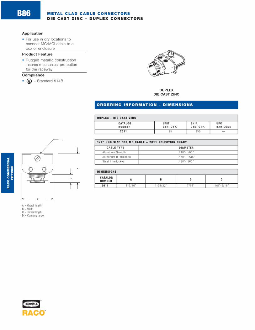
METAL CLAD CABLE CONNECTORSDIE CAST ZINC – DUPLEX CONNECTORS
B86
ORDERING INFORMATION - DIMENSIONS
DUPLEX DIE CAST ZINC
CATALOG UNIT SH IP UPCNUMBER CT N . QT Y. CT N . QT Y. BAR CODE
2 6 1 1 25 250 —
D U P L E X - D I E C A S T Z I N C
Application
• For use in dry locations to connect MC/MCI cable to a box or enclosure
Product Feature
• Rugged metallic constructioninsures mechanical protection for the raceway
Compliance
• – Standard 514B ®
A = Overall lengthB = WidthC = Thread lengthD = Clamping range
CATALOGNUMBER A B C D
2611 1-9/16" 1-21/32" 7/16" 1/8"-9/16"
D I M E N S I O N S
CABLE T YPE D IAMET ER
Aluminum Smooth .410"- .500"
A luminum In te r locked .460" - .538"
Stee l I n te r locked .438"- .560"
1 / 2 " H U B S I Z E F O R M C C A B L E – 2 6 1 1 S E L E C T I O N C H A R T
RA
CO
CO
MM
ER
CIA
L
FIT
TIN
GS

NONMETALLIC SHEATHED CABLE CONNECTORSSNAP-IN TYPE
B87
ORDERING INFORMATION - DIMENSIONS
SNAP-IN TYPE NONMETALLIC
CATALOG TRADE NONMETALL IC UN IT SH IP UPCNUM BER S IZE CABLE S IZE CT N . QT Y. CT N . QT Y. BAR CODE
S ing le 14-2 min to10-3 max , Doub le
4712 1/2"14-2 min to 12-2 max .
500 500 —Flex ib le CordS ing le .300 to .600 d ia .Two cords @ .300 d ia .
S ing le 14-2 min to10-3 max , Doub le
4713 1/2"14-2 min to 12-2 max .
50 200 —Flex ib le CordS ing le .300 to .600 d ia .Two cords @ .300 d ia .
S ing le 14-2 min to10-3 max , Doub le
4712-8 1/2"14-2 min to 12-2 max . 10 pcs 10 bagsF lex ib le Cord per bag per c tnS ing le .300 to .600 d ia .Two cords @ .300 d ia .
S N A P - I N T Y P E - N O N M E TA L L I C
A = Overall lengthB = Length snap-in hubC = Maximum body width
CATALOGNUMBER A B C
4712 1-11/32" 1/2" 1-3/32"
4712-8 1-11/32" 1/2" 1-3/32"
4713 1-11/32" 1/2" 1-3/32"
D I M E N S I O N S
Application
• For use in dry locations for connecting Nonmetallic SheathedCable (NMSC) to a box or an enclosure
Product Features
• One-piece nonmetallic construction-resists corrosion and offers insulation protection
• Snap-in design for 1/2" K.O.’s –locks into the knockout securely. No need to waste time withinstalling locknuts
• Captive locking wedge – no need to worry about missing components
• Easier to install than a standard die cast NMSC connector. Noneed to remove and retighten locknuts and cable clip screws.Just snap our connector into a box, insert the cable and compress the locking wedge
• Multipurpose design - offers installation flexibility. These connectors can accommodate a single run of 14-2 to 10-3 cable,a double run of 14-2 to 12-2cable, and one or more .300 inchor one .600 inch diameter cord
• Innovative packaging configurations- Bulk packaging option savesvolume users time and money.Smaller size carton quantities offer purchasing flexibility
• UPC bar coded fittings are individually polybagged with a preprinted UPC-A bar code and packaged in pre-scored tear top cartons for an attractive presentation
Compliances• – Standard 514B
• – For single cable and cord only
®
®
RA
CO
CO
MM
ER
CIA
L
FIT
TIN
GS
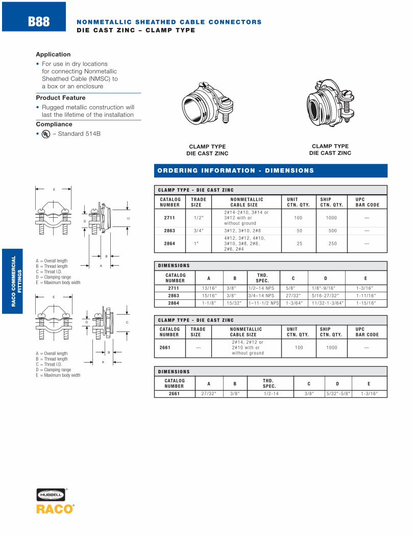
NONMETALLIC SHEATHED CABLE CONNECTORSDIE CAST ZINC – CLAMP TYPE
B88
ORDERING INFORMATION - DIMENSIONS
CLAMP TYPE DIE CAST ZINC
CATALOG TRADE NONMETALL IC UN IT SH IP UPCNUM BER S IZE CABLE S IZE CT N . QT Y. CT N . QT Y. BAR CODE
2#14-2#10, 3#14 o r2711 1/ 2" 3#12 w i th o r 100 1000 —
wi thou t g round
2863 3/ 4" 3#12, 3#10, 2#8 50 500 —
4#12, 3#12, 4#10,2864 1" 3#10, 3#8, 2#8, 25 250 —
2#6, 2#4
C L A M P T Y P E - D I E C A S T Z I N C
A = Overall lengthB = Thread lengthC = Throat I.D.D = Clamping rangeE = Maximum body width
CATALOG THD.NUMBER A B SPEC. C D E
2711 13/16" 3/8" 1/2–14 NPS 5/8" 1/8"-9/16" 1-3/16"
2863 15/16" 3/8" 3/4–14 NPS 27/32" 5/16-27/32" 1-11/16"
2864 1-1/8" 15/32" 1–11-1/2 NPS 1-3/64" 11/32-1-3/64" 1-15/16"
D I M E N S I O N S
Application
• For use in dry locations for connecting NonmetallicSheathed Cable (NMSC) to a box or an enclosure
Product Feature
• Rugged metallic construction will last the lifetime of the installation
Compliance
• – Standard 514B®
CLAMP TYPE DIE CAST ZINC
CATALOG TRADE NONMETALLIC UNIT SHIP UPCNUMBER SIZE CABLE SIZE CTN. QTY. CTN. QTY. BAR CODE
2#14, 2#12 o r2661 — 2#10 w i th o r 100 1000 —
wi thou t g round
C L A M P T Y P E - D I E C A S T Z I N C
A = Overall lengthB = Thread lengthC = Throat I.D.D = Clamping rangeE = Maximum body width
CATALOG THD.NUMBER A B SPEC. C D E
2661 27/32" 3/8" 1/2-14 3/8" 5/32"-5/8" 1-3/16"
D I M E N S I O N S
RA
CO
CO
MM
ER
CIA
L
FIT
TIN
GS

CATALOG UNIT SHIP UPCNUMBER DESCRIPTION CTN. QTY. CTN. QTY. BAR CODE
2709 Nai l ing spurs — 100
2710 Nai l ing spurs — 200 —
NONMETALLIC SHEATHED CABLE CONNECTORSSTEEL – ACCESSORIES
B89
ORDERING INFORMATION - DIMENSIONS
CABLE PROTECTOR STEEL
Application
• For use when protection isrequired for cable passing through a wood stud
Product Features
• Extra large plate provides a greater area of protection
• Pregalvanized for added corrosion protection
• Meets 1999 NEC Article 300-4 (A)
• UPC bar coded fittings are individually polybagged with a preprinted UPC-A bar code and packaged in pre-scored tear top cartons for an attractive presentation
Compliances
• – Standard 514B
• – Certified for Canada®
A = WidthB = HeightC = Thickness – measured from the tip of the tang
CATALOGNUMBER A B C D
2709 1-1/2" 3" 1/2" 1/16"
2710 1-1/2" 3" 1/2" 1/16"
D I M E N S I O N S
C A B L E P R O T E C T O R - S T E E L
RA
CO
CO
MM
ER
CIA
L
FIT
TIN
GS
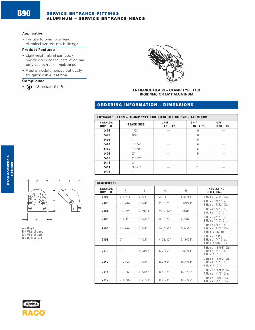
SERVICE ENTRANCE FITTINGSALUMINUM – SERVICE ENTRANCE HEADS
B90
Application
• For use to bring overhead electrical service into buildings
Product Features
• Lightweight aluminum body construction eases installation andprovides corrosion resistance
• Plastic insulator snaps out easilyfor quick cable insertion
Compliance
• – Standard 514B®
ENTRANCE HEADS – CLAMP TYPE FOR RIGID/IMC OR EMT ALUMINUM
CATALOG UNIT SH IP UPCNUMBER TRADE S IZE CTN . QTY. CTN . QTY. BAR CODE
2402 1/ 2" — 10 —
240 3 3/ 4" — 10 —
240 4 1" — 5 —
240 5 1-1/ 4" — 10 —
240 6 1-1/ 2" — 5 —
240 8 2" — 5 —
241 0 2 -1/ 2" — 1 —
241 2 3" — 1 —
241 4 3 -1/ 2" — 1 —
241 6 4" — 1 —
E N T R A N C E H E A D S – C L A M P T Y P E F O R R I G I D / I M C O R E M T - A L U M I N U M
A = HeightB = Width of clampC = Width of headD = Depth of head
CATALOG INSULAT INGNUMBER A B C D HOLE D IA .
2402 2-11/16" 2-1/4" 2-1/8" 2-37/64" 4 Holes 19/64" Dia .
2 Ho les 3/8" D ia . ,2403 2-55/64" 2-1/4" 2-9/32" 2-63/64" 3 Holes 13/32" Dia .
3 Ho les 1/2" D ia . ,2404 3-9/32" 2-39/64" 2-39/64" 3-3/8" 2 Holes 7/16" Dia .
3 Ho les 5/8" D ia . ,2405 3-1/4" 3-3/32" 3-3/32" 4-7/32" 2 Holes 7/16" Dia .
3 Ho les 3/4" D ia . ,2406 4-43/64" 3-3/4" 3-13/32" 5-3/32" 2 Holes 19/32" Dia . ,
1 Ho le 7/16" Dia .
3 Ho les 1" D ia . ,2408 6" 4-1/2" 4-23/32" 6-19/32" 2 Holes 3/4" D ia . ,
1 Ho le 17/32" Dia .
3 Ho les 1-5/16" Dia . ,2410 8" 5-13/16" 6-7/16" 9-57/64" 3 Holes 7/8" D ia . ,
1 Ho le 1" D ia .
3 Ho les 1-5/16" Dia . ,2412 8-7/64" 6-3/8" 6-7/16" 10-1/64" 3 Holes 7/8" D ia . ,
1 Ho le 1" D ia .
3 Ho les 1-5/16" Dia . ,2414 9-9/16" 7-7/64" 8-5/32" 13-1/16" 4 Holes 1-1/8" D ia .
3 Ho les 1-3/4" D ia . ,2416 9-11/32" 7-61/64" 8-5/32" 13-7/32" 4 Holes 1-1/8" D ia .
D I M E N S I O N S
ORDERING INFORMATION - DIMENSIONS
RA
CO
CO
MM
ER
CIA
L
FIT
TIN
GS

SERVICE ENTRANCE FITTINGSALUMINUM – SERVICE ENTRANCE HEADS AND BELL ENTRANCE ELLS
B91
ENTRANCE HEADS – CLAMP TYPE FOR SEU CABLE
ALUMINUM
BELL ENTRANCE ELLS
ALUMINUM
CATALOG UNIT SHIP UPCNUMBER TRADE SIZE CTN. QTY. CTN. QTY. BAR CODE
EASLB-1CG 1/ 2" 12 E-PAK
EASLB-2CG 3/ 4" 15 E-PAK
EASLB-3CG 1" 5 E-PAK
EASLB-4CG 1-1/ 4" 5 E-PAK
EASLB-5CG 1-1/ 2" 5 E-PAK
EASLB-6CG 2" 2 E-PAK
B E L L E N T R A N C E E L L S - A L U M I N U M
CATALOG NOMINAL UNIT SH IP UPCNUMBER CABLE S IZES CT N . QT Y. CT N . QT Y. BAR CODE
2430 3-#8 Through 3-#1— 10 —
1-#6 Through 1-#3
2440 3-#3/0 Through 3-#4/0— 10 —
1-#1/0 Through 1-#2/0
E N T R A N C E H E A D S – C L A M P T Y P E F O R S E U C A B L E - A L U M I N U M
Aluminum Service Entrance Heads Application
• For use to bring overhead electrical service into buildings
Aluminum Service Entrance Heads Product Features
• Lightweight aluminum body construction eases installation andprovides corrosion resistance
• Plastic insulator snaps out easilyfor quick cable insertion
Compliance
• – Standard 514B
Bell Entrance Ells Application
• For use with conduit to act as an elbow between serviceentrance and vertical entrancehead conduit runs
Bell Entrance Ells Product Features
• Lightweight aluminum construction eases installation and provides corrosion resistance
• Removable cover and gasketallows for easier wire pulling andaccess to the raceway
• Unique E-PAK packaging serves as a shipping and display carton
Compliances
• – Standard 514B
• – C22.2 #18®
®
®
CATALOG CONDUITNUMBER S IZE A B C
EASLB-1CG 1/2" 1-3/8" 1-13/32" 3-8/32"
EASLB-2CG 3/4" 1-31/64" 1-42/64" 3-13/16"
EASLB-3CG 1" 2-1/8" 1-9/16" 4-5/16"
EASLB-4CG 1-1/4" 2-3/16" 2-7/16" 5-9/16"
EASLB-5CG 1-1/2" 2-19/32" 2-3/8" 6-1/4"
EASLB-6CG 2" 3-1/8" 3-8/64" 6-3/4"
D I M E N S I O N S
CATALOGNUMBER A B C D E
2430 8–32 x 1 /2" 10–24 x 1" 17/32" 3-5/16" 3-5/16"
2440 12–24 x 1 /2" 12–24 x 1" 13/16" 4-1/2" 5"
D I M E N S I O N S
A = Cover screw specB = Clamp screw specC = Hole sizeD = Depth of headE = Height
ORDERING INFORMATION - DIMENSIONS
RA
CO
CO
MM
ER
CIA
L
FIT
TIN
GS

SERVICE ENTRANCE FITTINGSALUMINUM/NYLON/STEEL – UNDERGROUND FEEDER (UF)CONNECTORS
B92
Application
• For use with underground feeder(UF) cable to provide a liquid tight connection to meters and enclosures
Product Features
• Rugged metallic construction willlast the life of the installation
• Use a nylon connector when a lightweight corrosion resistantconnection is required
Compliances
• – Standard 514B
• – C22.2 #18®
®
UF CONNECTORS - LIQUID TIGHTSTEEL
UF CONNECTORS - LIQUID TIGHTNYLON
UF CONNECTORS - LIQUID TIGHTALUMINUM
UF* UN IT SH IP UPCCATALOG TRADE GROMMET WIRE CTN . CTN . BARNUMBER S IZE OPEN ING S IZE QTY. QTY. CODE
Min imum .20" x .40" 2#144899-9 1/ 2" Max imum .25" x .55" 2#12 — 10 —
2#10
U F C O N N E C T O R S - L I Q U I D T I G H T - A L U M I N U M
*Wi re s i zes va r y among manufac tu re rs
UF* UN IT SH IP UPCCATALOG TRADE GROMMET WIRE CTN . CTN . BARNUMBER S IZE OPEN ING S IZE QTY. QTY. CODE
Min imum .20" x .40" 2#144799-1 1/ 2" Max imum .25" x .55" 2#12 — 25 —
2#10
Min imum .20" x .60" 3#144799-3 3/ 4" Max imum .26" x .78" 3#12 — 15 —
3#10
U F C O N N E C T O R S - L I Q U I D T I G H T - N Y L O N
*Wi re s i zes va r y among manufac tu re rs
UF* UNIT SHIP UPCCATALOG TRADE GROMMET WIRE CTN. CTN. BARNUMBER SIZE OPENING SIZE QTY. QTY. CODE
2462 1/2"Min imum .225" 2#14
25 100 —Max imum .425" 2#12
U F C O N N E C T O R S - L I Q U I D T I G H T - S T E E L
*Wi re s i zes va r y among manufac tu re rs
A = Nut O.D.B = Length nut to shoulderC = Thread lengthD = Throat I.D.E = Shoulder O.D.F = Thread spec
TRADE E
SIZEA B C D
A/C* A/F**F
4899-9 1.13" 1.10" .55" .64" 1.11" 1.00" 1/2"–14
4799-1 1.32" 1.50" .53" .58" 1.25" 1.12" 1/2"–14
4799-3 1.56" 1.60" .55" .77" 1.44" 1.31" 3/4"–14
2462 1-1/4" 3/4" 19/32" 1/2" 1-1/16" 15/16" 1/2"–14
D I M E N S I O N S
* A/C Across co rners
** A/F Across f l a t s
ORDERING INFORMATION - DIMENSIONS
RA
CO
CO
MM
ER
CIA
L
FIT
TIN
GS
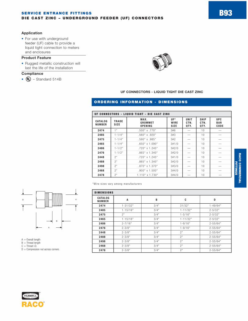
SERVICE ENTRANCE FITTINGSDIE CAST ZINC – UNDERGROUND FEEDER (UF) CONNECTORS
B93
UF CONNECTORS - LIQUID TIGHT DIE CAST ZINC
MAX. UF* UNIT SHIP UPCCATALOG TRADE GROMMET WIRE CTN. CTN. BARNUMBER SIZE OPENING SIZE QTY. QTY. CODE
2474 1" .500" x .770" 3#6 — 10 —
2485 1-1/ 4" .560" x .920" 3#3 — 10 —
2475 1-1/ 4" .590" x .985" 3#2 — 10 —
2465 1-1/ 4" .650" x 1 .090" 3#1/0 — 10 —
2486 1-1/ 2" .720" x 1 .245" 3#2/0 — 10 —
2476 1-1/ 2" .865" x 1 .340" 3#2/0 — 10 —
2448 2" .720" x 1 .245" 3#1/0 — 10 —
2488 2" .865" x 1 .340" 3#2/0 — 10 —
2498 2" .870" x 1 .370" 3#3/0 — 10 —
2468 2" .900" x 1 .500" 3#4/0 — 10 —
2478 2" 1.110" x 1 .730" 3#4/0 — 10 —
U F C O N N E C T O R S - L I Q U I D T I G H T - D I E C A S T Z I N C
A = Overall lengthB = Thread lengthC = Throat I.D.D = Compression nut across corners
Application
• For use with underground feeder (UF) cable to provide a liquid tight connection to metersand enclosures
Product Feature
• Rugged metallic construction willlast the life of the installation
Compliance
• – Standard 514B®
CATALOGNUMBER A B C D
2474 1-31/32" 3/4" 31/32" 1-49/64"
2485 1-15/16" 3/4" 1-11/32" 2-5/32"
2475 2" 3/4" 1-5/16" 2-5/32"
2465 1-15/16" 3/4" 1-11/32" 2-5/32"
2486 2-7/16" 3/4" 1-9/16" 2-55/64"
2476 2-3/8" 3/4" 1-9/16" 2-55/64"
2448 2-3/8" 3/4" 2" 2-55/64"
2488 2-3/8" 3/4" 2" 2-55/64"
2498 2-3/8" 3/4" 2" 2-55/64"
2468 2-3/8" 3/4" 2" 2-55/64"
2478 2-3/8" 3/4" 2" 2-55/64"
D I M E N S I O N S
*Wi re s i zes va r y among manufac tu re rs
ORDERING INFORMATION - DIMENSIONS
RA
CO
CO
MM
ER
CIA
L
FIT
TIN
GS

SERVICE ENTRANCE FITTINGSDIE CAST ZINC – NON-WATERTIGHT CONNECTORS
B94
ORDERING INFORMATION - DIMENSIONS
Application
• For use with underground feeder (UF) cable to provide a non-watertight connection tometers and enclosures
Product Feature
• Rugged metallic construction willlast the lifetime of the installation
Compliance
• – Standard 514B®
CONNECTORS FOR OVAL CABLE DIE CAST ZINC
CONNECTORS FOR OVAL OR ROUND CABLE
DIE CAST ZINC
CATALOG TRADE NOMINAL UNIT SH IP UPCNUMBER S IZE CABLE S IZE CT N . QT Y. CT N . QT Y. BAR CODE
2853 3/ 4" 3#8, 3#6 — 25 —
2854 1" 3#6, 3#4 — 25 —
2855 1-1/ 4" 3#2, 3#3 — 10 —
2856 1-1/ 2" 3#1/0 , 3#2/0 , 3#1 — 10 —
2858 2" 3#3/0 , 3#4/0 — 10 —
C O N N E C T O R S F O R O VA L C A B L E - D I E C A S T Z I N C
CATALOG TRADE NOMINAL UNIT SH IP UPCNUMBER S IZE CABLE S IZE CT N . QT Y. CT N . QT Y. BAR CODE
2863 3/ 4" 3#10, 3#6, 2#6 50 500 —
2864 1" 3#6, 3#4 25 250 —
C O N N E C T O R S F O R O VA L O R R O U N D C A B L E - D I E C A S T Z I N C
A = Overall lengthB = Thread length and thread specC = Throat I.D.D = Clamping rangeE = Maximum body width
CATALOG THD.NUMBER A B SPEC . C D E
2853 1-5/16" 3/8" 3/4-14 NPS 27/32" 5/16"-27/32" 1-11/16"
2854 1-1/8" 15/32" 1-11-1/2 NPS 1-3/64" 11/32”-1-3/64" 1-15/16"
2855 1-1/4" 19/32" 1-1/4-11-1/2 NPS 1-3/8" 3/8"-15/16" 2-3/16"
2856 1-5/16" 5/8" 1-1/2-11-1/2 NPS 1-14/32" 5/8"-1-19/32" 2-19/32"
2858 1-9/16" 3/4" 2-11-1/2 NPS 2-1/16" 7/8"-2-1/16" 2-15/16"
2863 15/16" 3/8" 3/4-14 NPS 27/32" 5/16"-27/32" 1-11/16"
2864 1-1/8" 19/32" 1-11-1/2 NPS 1-3/64" 11/32"-1-3/64" 1-15/16"
D I M E N S I O N S
RA
CO
CO
MM
ER
CIA
L
FIT
TIN
GS

SERVICE ENTRANCE FITTINGSSTEEL – STRAPS
B95
STRAPS STEEL
A = Overall lengthB = HeightC = Hole sizeD = Width of strapE = Inside length
Application
• For use in mounting serviceentrance cable
Product Features
• All steel construction providesdurability of installation
• Electro zinc plated for addedcorrosion protection
Compliances
• – Standard 514B
• – Certified for Canada®
CATALOGNUMBER A B C D E
2441 1-5/8" 37/64" 9/32" 5/8" 13/16"
2442 1-55/64" 3/4" 9/32" 5/8" 1-3/64"
2443 1-21/32" 1" 9/32" 1" 1-7/16"
2444 2-59/64" 1-9/64" 9/32" 1" 1-45/64"
D I M E N S I O N S
CATALOG NOMINAL UNIT SH IP UPCNUM BER CABLE S IZE CT N . QT Y. CT N . QT Y. BAR CODE
2441 3#8, 3#6 — 100 —
2442 3#4, 3#3, 3#2 — 100 —
2443 3#1, 3#1/0 , 3#2/0 — 50 —
2444 3#3/0 , 3#4/0 — 50 —
S T R A P S – S T E E L
ORDERING INFORMATION - DIMENSIONS
RA
CO
CO
MM
ER
CIA
L
FIT
TIN
GS

MISCELLANEOUS FITTINGSBRONZE – GROUND CLAMPS
B96
FOR BARE GROUND WIRES BRONZE ALLOY
FOR BARE ARMORED GROUND WIRE BRONZE ALLOY
Application
• For use in grounding wire or conduit to water pipes orground rods
Product Feature
• Bronze cast construction assures ground path continuity and provides corrosion resistance
Compliance
• – Standard 514B®
CATALOG P IPE GROUNDING UNIT SH IP UPCNUM BER S IZE CONDUCT OR S IZE CT N . QT Y. CT N . QT Y. BAR CODE
2504 1/ 2" -1" No. 2 S t r. /No . 10 So l . — 25 —
2505 1-1/ 4"- 2" No. 2 S t r. /No . 10 So l . — 25 —
F O R B A R E G R O U N D W I R E S - B R O N Z E A L L OY
CATALOG P IPE GROUNDING UNIT SH IP UPCNUMBER S IZE CONDUCT OR S IZE CT N . QT Y. CT N . QT Y. BAR CODE
2507 1/ 2”- 1" No. 6 S t r. /No . 10 So l . — 25 —
2508 1-1/ 4"- 2" No. 6 S t r. /No . 10 So l . — 25 —
F O R B A R E A R M O R E D G R O U N D W I R E - B R O N Z E A L L OY
A = WidthB = Hole diameterC = HeightD = Min./Max. clamping range
A = WidthB = LengthC = HeightD = Min./Max. clamping range
CATALOGNUMBER A B C D
2504 2-1/4" 5/16" 2-5/16" 11/16"-1-5/16"
2505 3-9/16" 5/16" 3-1/8" 1-3/8"-2-1/2"
D I M E N S I O N S
CATALOGNUMBER A B C D
2507 2-1/4" 2-3/8" 2-3/4" 9/16"-1-5/16"
2508 3-5/8" 2-1/4" 3-5/8" 1-3/8"-2-1/2"
D I M E N S I O N S
ORDERING INFORMATION - DIMENSIONS
RA
CO
CO
MM
ER
CIA
L
FIT
TIN
GS

MISCELLANEOUS FITTINGSBRONZE – GROUND CLAMPS
B97
ORDERING INFORMATION - DIMENSIONS
FOR 3/4" RIGID CONDUITBRONZE ALLOY
FOR 1/2" RIGID CONDUITBRONZE ALLOY
CATALOG P IPE GROUNDING UNIT SH IP UPCNUMBER S IZE CONDUCT OR S IZE CT N . QT Y. CT N . QT Y. BAR CODE
2512 1/ 2" - 1" No. 6 S t r. /No . 10 So l . — 25 —
2522 1-1/ 4"- 2" No. 6 S t r. /No . 10 So l . — 25 —
F O R 1 / 2 " R I G I D C O N D U I T - B R O N Z E A L L OY
CATALOG P IPE GROUNDING UNIT SH IP UPCNUMBER S IZE CONDUCT OR S IZE CT N . QT Y. CT N . QT Y. BAR CODE
2513 1/ 2" - 1" No. 2/0 S t r. /No . 10 So l . — 25 —
2523 1-1/ 4" - 2" No. 2/0 S t r. /No . 10 So l . — 25 —
F O R 3 / 4 " R I G I D C O N D U I T - B R O N Z E A L L OY
A = WidthB = LengthC = HeightD = Min./Max. clamping range
Application
• For use in grounding wire or conduit to water pipes or ground rods
Product Feature
• Bronze cast construction assures ground path continuity and provides corrosion resistance
Compliance
• – Standard 514B®
CATALOGNUMBER A B C D
2512 2-1/4" 2-1/2" 3-1/8" 5/8"-1-3/8"
2522 3-9/16" 1-15/16" 3-1/2" 1-1/4"-2-1/2"
2513 2-5/16" 2-1/8" 3-1/2" 11/16"-1-3/8"
2523 3-5/8" 2-3/16" 4-3/8" 1-7/16"-2-1/2"
D I M E N S I O N S
RA
CO
CO
MM
ER
CIA
L
FIT
TIN
GS
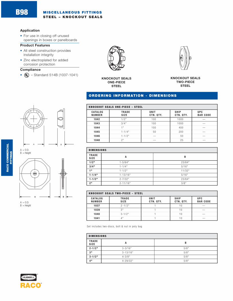
MISCELLANEOUS FITTINGSSTEEL – KNOCKOUT SEALS
B98
Application
• For use in closing off unusedopenings in boxes or panelboards
Product Features
• All steel construction providesinstallation integrity
• Zinc electroplated for addedcorrosion protection
Compliance
• – Standard 514B (1037-1041)®
KNOCKOUT SEALS TWO-PIECE
STEEL
KNOCKOUT SEALS ONE-PIECE
STEEL
CATALOG TRADE UNIT SH IP UPCNUMBER S IZE CT N . QT Y. CT N . QT Y. BAR CODE
1042 1/ 2" 100 1000 —
1043 3/ 4" 100 1000 —
1044 1" 100 400 —
1045 1-1/ 4" 50 200 —
1046 1-1/ 2" — 50 —
1048 2" — 25 —
K N O C K O U T S E A L S O N E - P I E C E - S T E E L
CATALOG TRADE UNIT SH IP UPCNUMBER S IZE CT N . QT Y. CT N . QT Y. BAR CODE
1037 2 -1/ 2" 1 10 —
1039 3" 1 10 —
1040 3-1/ 2" 1 10 —
1041 4" 1 10 —
K N O C K O U T S E A L S T W O - P I E C E - S T E E L
Set inc ludes two-d iscs , bo l t & nu t in po ly bag
A = O.D.B = Height
A = O.D.B = Height
D I M E N S I O N S
TRADES IZE A B
1/2" 1-5/64" 23/64"
3/4" 1-1/4" 5/16"
1" 1-1/2" 11/32"
1-1/4" 1-13/16" 5/16"
1-1/2" 2-7/32" 23/64"
2" 2-11/16" 3/8"
D I M E N S I O N S
TRADES IZE A B
2-1 /2" 3-3/16" 5/8"
3" 3-13/16" 5/8"
3-1 /2" 4-3/8" 5/8"
4" 4-29/32" 5/8"
ORDERING INFORMATION - DIMENSIONS
RA
CO
CO
MM
ER
CIA
L
FIT
TIN
GS

MISCELLANEOUS FITTINGSSTEEL/MALLEABLE IRON – BEAM CLAMPS AND CABLE PROTECTORS
B99
ORDERING INFORMATION - DIMENSIONS
CABLE PROTECTOR STEEL
BEAM CLAMPS STEELMALLEABLE IRON
CATALOG TRADE MAX SHIP UPCNUMBER S IZE LOAD LBS . CTN . QTY. BAR CODE
2500* 1" 125 100 —
2524 1" 335 100 —
2536 1-1/ 2" 525 50 —
2538 2" 750 25 —
2510 2-1/ 2" 900 25 —
B E A M C L A M P S - S T E E L - M A L L E A B L E I R O N
* Ca t . No . 2500 i s s tee l
CATALOG UNIT SH IP UPCNUMBER DESCRIPT ION CTN . QTY. CTN . QTY. BAR CODE
2710 Na i l i ng Spurs — 200 —
2709 Na i l i ng Spurs — 100
C A B L E P R O T E C T O R - S T E E L
Beam Clamps Application
• For use with hangers, bridle ringsand drop rods to support conduitfrom I-beams
Beam Clamps Product Features
• Rugged steel/malleable ironconstruction will last the lifetime of the installation
• Zinc electro plated for corrosionresistance
Steel Cable Protector Application
• For use when protection isrequired for cable passing through a wood stud
Steel Cable Protector Product Features
• Extra large plate provides a greater area of protection
• Pregalvanized for added corrosion protection
Compliances• – Standard 514B
(Steel Cable Protectors)
• – C22.2 #18 (Steel Cable Protectors)
®
D I M E N S I O N S
CATALOGNUMBER A B C
2500 1-15/16" 1/4"–20 5/8"
2524 1-5/16" 1/4"–20 27/32"
2536 1-3/4" 5/16"–18 11/16"
2538 1-7/8" 3/8"–16 15/16"
2510 2-11/32" 1/2"–13 31/32”
D I M E N S I O N S
CATALOGNUMBER A B C D
2709 1-1/2" 3" 1/2" 1/16"
2710 1-1/2" 3" 1/2" 1/16"
A = Base lengthB = Thread sizeC = Inside openingD = Base widthE = HeightF = Bolt size
A = WidthB = HeightC = Thickness – measured from the tip of the tang
RA
CO
CO
MM
ER
CIA
L
FIT
TIN
GS

MISCELLANEOUS FITTINGSSTEEL – REDUCING WASHERS
B100
ORDERING INFORMATION - DIMENSIONS
Application
• For use when a raceway is smallerin trade size than the trade size ofthe knockout it is intended to enter
• Use reducing washers in pairs.One inside and one outside thebox or enclosure
Product Features
• All steel construction providesinstallation integrity
• Each reducing washer is stampedwith trade size information for ease of product identification
• Zinc electro plated for addedcorrosion protection
REDUCING WASHERS STEEL
CATALOG TRADE UNIT SH IP UPCNUMBER S IZE CT N . QT Y. CT N . QT Y. BAR CODE
1365 3/ 4"-1/ 2" 200 1000 —
1366 1"-1/ 2" 100 1000 —
1367 1"-3/ 4" 100 1000 —
1368 1-1/ 4"-1/ 2" — 100 —
1369 1-1/ 4"-3/ 4" — 100 —
1370 1-1/ 4"-1" — 100 —
1371 1-1/ 2"-1/ 2" — 50 —
1372 1-1/ 2"-3/ 4" — 50 —
1373 1-1/ 2"-1" — 50 —
1374 1-1/ 2"-1-1/ 4" — 50 —
1375 2”-1/ 2" — 50 —
1376 2"-3/ 4" — 50 —
1377 2"-1" — 50 —
1378 2"-1-1/ 4" — 50 —
1379 2"-1-1/ 2" — 50 —
1380 2 -1/ 2"-1" — 50 —
1381 2 -1/ 2"-1-1/ 4" — 50 —
1382 2 -1/ 2"-1-1/ 2" — 50 —
1383 2 -1/ 2"-2" — 50 —
1384 3"-1-1/ 4" — 25 —
1385 3"-1-1/ 2" — 25 —
1386 3"-2" — 25 —
1387 3"-2 -1/ 2" — 25 —
1389 3 -1/ 2"-2" — 10 —
1390 3 -1/ 2"-2 -1/ 2" — 10 —
1391 3 -1/ 2"-3" — 10 —
1392 4"-2" — 10 —
1393 4"-2 -1/ 2" — 10 —
1394 4"-3" — 10 —
R E D U C I N G W A S H E R S - S T E E L
A = Across flatsB = I.D.
D I M E N S I O N S
CATALOGNUMBER A B
1365 1-1/4" 7/8"
1366 1-17/32" 7/8"
1367 1-17/32" 1-3/32"
1368 1-31/32" 7/8"
1369 1-31/32" 1-3/32"
1370 1-31/32" 1-11/32"
1371 2-1/8" 7/8"
1372 2-1/8" 1-3/32"
1373 2-1/8" 1-11/32"
1374 2-1/8" 1-11/16"
1375 2-11/16" 7/8"
1376 2-11/16" 1-3/32"
1377 2-11/16" 1-11/32"
1378 2-11/16" 1-11/16"
1379 2-11/16" 1-15/16"
1380 3-3/16" 1-11/32"
1381 3-3/16" 1-11/16"
1382 3-3/16" 1-15/16"
1383 3-3/16" 2-15/32"
1384 3-3/16" 1-11/16"
1385 3-3/16" 1-15/16"
1386 3-3/16" 2-15/32"
1387 3-3/16" 3"
1389 4-3/8" 2-15/32"
1390 4-3/8" 3"
1391 4-3/8" 3-5/8"
1392 4-29/32" 2-15/32"
1393 4-29/32" 3"
1394 4-29/32" 3-5/8"
RA
CO
CO
MM
ER
CIA
L
FIT
TIN
GS

MISCELLANEOUS FITTINGSDIE CAST ZINC – OFFSET NIPPLES
B101
Application
• For use when connecting two boxes or panels when the knockouts are not in line
Product Feature
• Rugged metallic construction provides mechanical protection for the conductors
Compliance
• – Standard 514B ®
3/4” OFFSET NIPPLESDIE CAST ZINC
CATALOG TRADE UNIT SH IP UPCNUM BER S IZE CT N . QT Y. CT N . QT Y. BAR CODE
1452 1/ 2" — 50 —
1453 3/ 4" — 20 —
1454 1" — 15 —
1455 1-1/ 4" — 10 —
1456 1-1/ 2" — 10 —
1458 2" — 6 —
3 / 4 " O F F S E T N I P P L E S - D I E C A S T Z I N C
A = Overall lengthB = Throat I.D.C = Thread lengthD = Amount of offset
CATALOG TRADENUMBER S IZE A B C D
1452 1/2" 2-7/16" 39/64" 3/8" 3/4"
1453 3/4" 2-9/16" 7/8" 15/32" 3/4"
1454 1" 2-3/4" 1-3/64" 9/16" 3/4"
1455 1-1/4" 2-7/8" 1-3/8" 5/8" 3/4"
1456 1-1/2" 3-1/16" 1-19/32" 11/16" 3/4"
1458 2" 3-1/8" 2-1/16" 3/4" 3/4"
D I M E N S I O N S
ORDERING INFORMATION - DIMENSIONS
RA
CO
CO
MM
ER
CIA
L
FIT
TIN
GS

CATALOG TRADENUMBER S IZE A B C
1662 1/2" 11/16" 3/8" 1-1/64"
1663 3/4" 3/4" 17/32" 1-19/64"
1664 1" 7/8" 21/32" 1-17/32"
1665 1-1/4" 15/16" 11/16" 1-57/64"
1666 1-1/2" 29/32" 5/8" 2-19/64"
1668 2" 1-5/64" 49/64" 2-57/64"
1670 2-1/2" 1-3/8" 1" 3-25/64"
1672 3" 1-7/16" 1-1/16" 4-1/16"
1674 3-1/2" 1-15/32" 1-3/32" 4-39/64"
1676 4" 1-15/32" 1-3/32" 5-5/32"
D I M E N S I O N S
B102
ORDERING INFORMATION - DIMENSIONS
MISCELLANEOUS FITTINGSDIE CAST ZINC – UNINSULATED NIPPLES
Application
• For use with a conduit coupling toconnect conduit to a box or, with a locknut to connect two boxes
Product Feature
• Rugged metallic construction
Compliance
• – Standard 514B®
UNINSULATED NIPPLES DIE CAST ZINC
CATALOG TRADE UNIT SH IP UPCNUMBER S IZE CT N . QT Y. CT N . QT Y. BAR CODE
1662 1/ 2" 100 1000 —
1663 3/ 4" 50 500 —
1664 1" 25 250 —
1665 1-1/ 4" 25 250 —
1666 1-1/ 2" 25 100 —
1668 2" 10 40 —
1670 2 -1/ 2" 10 40 —
1672 3" 10 40 —
1674 3 -1/ 2" 10 40 —
1676 4" 5 20 —
U N I N S U L AT E D N I P P L E S - D I E C A S T Z I N C
A = Overall lengthB = Thread lengthC = Across corners
A B
C
RA
CO
CO
MM
ER
CIA
L
FIT
TIN
GS

MISCELLANEOUS FITTINGSSTEEL – CONDUIT HANGERS WITH BOLTS
B103
ORDERING INFORMATION - DIMENSIONS
Application
• For use in wet or dry locations tosupport runs of rigid/IMC and EMTconduit from ceilings and walls
Product Features
• Furnished with nut and bolt tospeed installation
• Pregalvanized finish providescorrosion protection
Compliances
• – Standard 514B(trade sizes 0-9)
• – Canada(trade sizes 0-9)
®
CONDUIT HANGERS WITH BOLTS STEEL
CATALOG TRADE R IG ID & IMC EMT SHIP UPCNUMBER S IZE S IZE S IZE CTN . QTY. BAR CODE
2052 0 3 / 8"-1/ 2" 1/ 2" 100 —
2053 1 3/ 4" 3/ 4" 100 —
2054 2 1" 1" 100 —
2041 2 -1/ 2 — 1-1/ 4" 100 —
2055 3 1-1/ 4" 1-1/ 2" 100 —
2056 4 1-1/ 2" — 100 —
2058 5 2" 2" 50 —
2057 6 2 -1/ 2" 2 -1/ 2" 25 —
2059 7 3" 3" 25 —
2060 8 3 -1/ 2" 3 -1/ 2" 10 —
2061 9 4" 4" 10 —
C O N D U I T H A N G E R S W I T H B O LT S - S T E E L
CATALOG TRADENUMBER S IZE A B C D E F G H I J BOLT & NUT
2052 0 25/32" 13/32" 13/16" 1-13/16" 53/64" 5/16" 7/16" 17/64" 19/64" 3/4" 1/4-20 x 1-3/8"bo l t / sq .nu t
2053 1 1-1/16" 9/16" 27/32" 2-1/16" 59/64" 5/16" 7/16" 17/64" 19/64" 7/8" 1/4-20 x 1-3/8"bo l t / sq .nu t
2054 2 1-13/64" 1/2" 15/16" 2-7/16" 1-5/32" 5/16" 1/2" 17/64" 19/64" 7/8" 1/4-20 x 1-3/8"bo l t / sq .nu t
2041 2-1/2 1-3/8" 13/32" 1" 2-27/32" 1-1/4" 5/16" 1/2" 17/64" 19/64" 7/8" 1/4-20 x 1-3/8"bo l t / sq .nu t
2055 3 1-19/32" 13/32" 1-3/32" 2-7/8" 1-3/8" 5/16" 1/2" 17/64" 19/64" 7/8" 1/4-20 x 1-3/8"bo l t / sq .nu t
2056 4 1-53/64" 13/32" 1-5/32" 3-1/4" 1-5/8" 5/16" 5/8" 21/64" 19/64" 1" 1/4-20 x 1-3/8"bo l t / sq .nu t
2058 5 2-11/32" 9/16" 1-3/16" 3-7/8" 1-3/4" 5/16" 9/16" 21/64" 19/64" 1-1/4" 1/4-20 x 1-3/8"bo l t / sq .nu t
2057 6 2-7/8" 1/2" 1-3/16" 4-7/16" 2-7/32" 11/32" 37/64" 5/16" 1/4" 1-1/4" 1/4-20 x 1-1/2"bo l t / sq .nu t
2059 7 3-1/2" 5/8" 1-5/32" 5" 2-1/2" 29/64" 5/8" 5/16" 5/16" 1-1/4" 5/16-1 x 1-1/2"bo l t / sq .nu t
2060 8 4" 3/4" 1-13/64" 5-1/2" 2-3/4" 29/64" 37/64" 5/16" 5/16" 1-1/4" 5/16-18 x 1-1/2"bo l t / sq nu t
2061 9 4-1/2" 1-1/2" 1-23/32" 7" 3-1/2" 25/32" 61/64" 1/2" 1/2" 1-3/4" 1/2-14 x 2-1/2"bo l t /hex nu t
D I M E N S I O N S
RA
CO
CO
MM
ER
CIA
L
FIT
TIN
GS
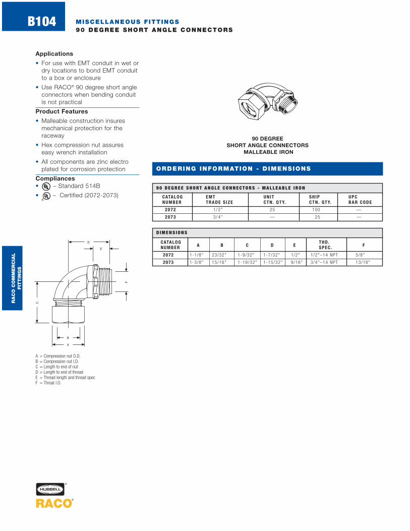
MISCELLANEOUS FITTINGS90 DEGREE SHORT ANGLE CONNECTORS
B104
ORDERING INFORMATION - DIMENSIONS
90 DEGREE SHORT ANGLE CONNECTORS
MALLEABLE IRON
CATALOG EMT UNIT SH IP UPCNUMBER T RADE S IZE CT N . QT Y. CT N . QT Y. BAR CODE
207 2 1/ 2" 25 100 —
207 3 3/ 4" — 25 —
9 0 D E G R E E S H O R T A N G L E C O N N E C T O R S - M A L L E A B L E I R O N
A = Compression nut O.D.B = Compression nut I.D.C = Length to end of nutD = Length to end of threadE = Thread length and thread specF = Throat I.D.
Applications
• For use with EMT conduit in wet ordry locations to bond EMT conduitto a box or enclosure
• Use RACO® 90 degree short angleconnectors when bending conduitis not practical
Product Features
• Malleable construction insuresmechanical protection for the raceway
• Hex compression nut assures easy wrench installation
• All components are zinc electroplated for corrosion protection
Compliances• – Standard 514B
• – Certified (2072-2073)®
CATALOG THD.NUMBER A B C D E SPEC . F
2072 1-1/8" 23/32" 1-9/32" 1-7/32" 1/2" 1/2"–14 NPT 5/8"
2073 1-3/8" 15/16" 1-19/32" 1-15/32" 9/16" 3/4"–14 NPT 13/16"
D I M E N S I O N S
RA
CO
CO
MM
ER
CIA
L
FIT
TIN
GS


