1 0353EN May 2017 RADIANT PLASTERBOARD CEILINGS GKCS RADIANT PLASTERBOARD CEILING PANEL PUSH- FIT TYPE PLASTIC FITTINGS RC102P - RC122P - RC151P - RC165P - RC211P ISO 14001 0032A/3 OHSAS 18001 0064L/1 ISO 9001 0006/7 Technical data • Pipe dimensions: Ø 8 x 1 mm • Total panel thickness: 45 mm • Radiant panels of B-s1,d0 fire class (EN 13501-1) Materials • Panel sheet: plasterboard • Pipes: Ø 8 x 1 mm plastic material with anti-oxygen barrier • Insulating layer: EPS150 • Pipe protection caps: plastic material Nominal yields • For cooling (in compliance with EN14240): 47,2 W/m² with water-ambient ∆T 10 K. • For heating (in compliance with EN14037): 62,4 W/m² with water-ambient ∆T 15 K. 0 5 10 15 22 20 ΔT water-ambient [K] 110 100 10 0 30 20 40 70 60 50 90 80 Capacity [W/m 2 of panel’s actual surface] Legend Heating Cooling NB: Outputs as per tests in a temperature-controlled enclosure. Outputs refer to the panel's actual surface. Components 2 4 1 3 Legend 1 15 mm thick plasterboard sheet 2 Ø 8 x 1 mm plastic material pipes with anti-oxygen barrier 3 30 mm thick EPS insulating layer 4 Pipe protection caps Description The panels of the GKCS 2.0 series, designed for the installation of heating and cooling radiant ceiling systems, consist in a 15 mm thick plasterboard and 30 mm thick thermal activation and sintered expanded polystyrene (EPS150) insulating layer, for a total thickness of 45 mm. Thermal activation consists of one or two hydraulic circuits executed using a 8 x 1 mm Pex pipe with anti-oxygen barrier, laid in a dedicated housing on the upper side of the plasterboard sheet. A single circuit is envisaged for 0,72 m 2 and 1,2 m 2 radiant panels, whilst two hydraulic circuits are envisaged for 2,4 m 2 radiant panels. The panel's different formats ensure system modularity and flexibility; non- activated panels, without hydraulic circuits, enable completing radiant surfaces with surrounding structural elements. The panels are connected to the distribution network with 8 x 1 mm pipes. Versions and product codes Product code Description Dimension [mm] Kv Weight [kg] Area [m 2 ] KS120Y200 Active 2 circuits 1200 x 2000 0,1 30 2,4 KS60Y200 Active 1 circuit 600 x 2000 0,1 15 1,2 KS60Y120 Active 1 circuit 600 x 1200 0,12 9 0,72 KS120X300 Inactive for compensation 1200 x 2000 - 30 2,4 NB: The 1200x1000 mm panel can be obtained by cutting panel KS120Y200 into two. The two circuits are completely separate. Warning. When cutting the KS120Y200 panel, pay attention to the drawing traced on the plasterboard's surface. GKCS 2.0
Technical data• Pipe dimensions: Ø 8 x 1 mm• Total panel thickness: 45 mm• Radiant panels of B-s1,d0 fire class (EN 13501-1)
Materials• Panel sheet: plasterboard• Pipes: Ø 8 x 1 mm plastic material with anti-oxygen barrier• Insulating layer: EPS150• Pipe protection caps: plastic material
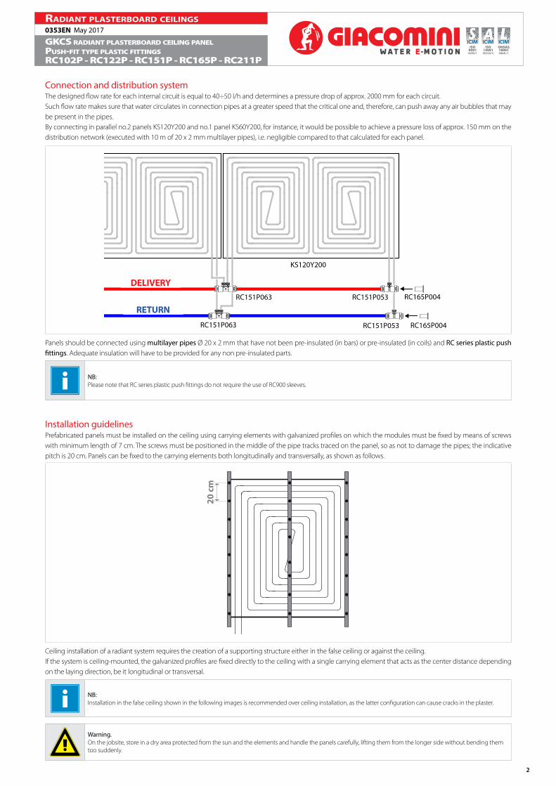
Nominal yields• For cooling (in compliance with EN14240): 47,2 W/m² with water-ambient ∆T 10 K.• For heating (in compliance with EN14037): 62,4 W/m² with water-ambient ∆T 15 K.
0 5 10 15 2220∆T water-ambient [K]
110
100
10
0
30
20
40
70
60
50
90
80
Capa
city
[W/m
2 of p
anel
’s ac
tual
sur
face
]
Legend
Heating Cooling
NB:Outputs as per tests in a temperature-controlled enclosure.Outputs refer to the panel's actual surface.
Components
2
4
1
3
Legend
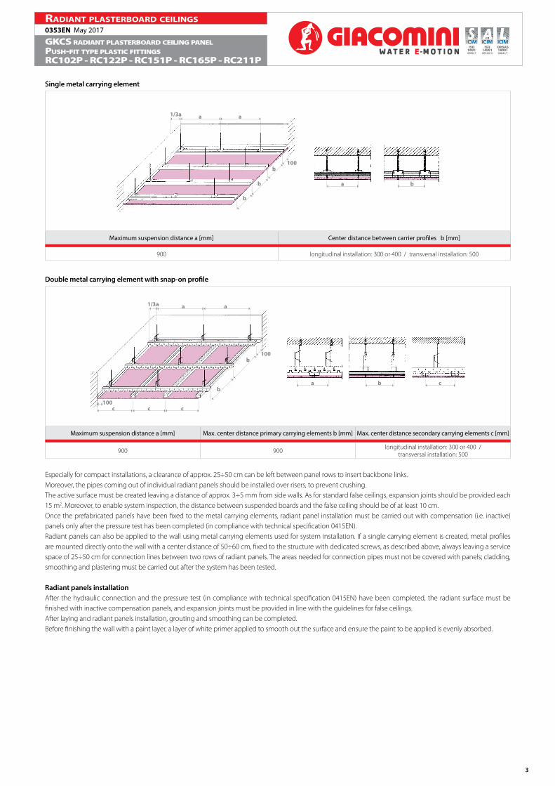
1 15 mm thick plasterboard sheet
2 Ø 8 x 1 mm plastic material pipes with anti-oxygen barrier
3 30 mm thick EPS insulating layer
4 Pipe protection caps
DescriptionThe panels of the GKCS 2.0 series, designed for the installation of heating and cooling radiant ceiling systems, consist in a 15 mm thick plasterboard and 30 mm thick thermal activation and sintered expanded polystyrene (EPS150) insulating layer, for a total thickness of 45 mm.Thermal activation consists of one or two hydraulic circuits executed using a 8 x 1 mm Pex pipe with anti-oxygen barrier, laid in a dedicated housing on the upper side of the plasterboard sheet.A single circuit is envisaged for 0,72 m2 and 1,2 m2 radiant panels, whilst two hydraulic circuits are envisaged for 2,4 m2 radiant panels.The panel's different formats ensure system modularity and flexibility; non-activated panels, without hydraulic circuits, enable completing radiant surfaces with surrounding structural elements.The panels are connected to the distribution network with 8 x 1 mm pipes.
Versions and product codes
Product code Description Dimension[mm] Kv Weight
[kg]Area[m2]
KS120Y200 Active2 circuits
1200 x 2000 0,1 30 2,4
KS60Y200 Active1 circuit
600 x 2000 0,1 15 1,2
KS60Y120 Active1 circuit
600 x 1200 0,12 9 0,72
KS120X300 Inactivefor compensation
1200 x 2000 - 30 2,4
NB:The 1200x1000 mm panel can be obtained by cutting panel KS120Y200 into two. The two circuits are completely separate.
Warning.When cutting the KS120Y200 panel, pay attention to the drawing traced on the plasterboard's surface.
Connection and distribution systemThe designed flow rate for each internal circuit is equal to 40÷50 l/h and determines a pressure drop of approx. 2000 mm for each circuit.Such flow rate makes sure that water circulates in connection pipes at a greater speed that the critical one and, therefore, can push away any air bubbles that may be present in the pipes.By connecting in parallel no.2 panels KS120Y200 and no.1 panel KS60Y200, for instance, it would be possible to achieve a pressure loss of approx. 150 mm on the distribution network (executed with 10 m of 20 x 2 mm multilayer pipes), i.e. negligible compared to that calculated for each panel.
RC165P004
RC165P004
RC151P053RC151P063
RC151P063 RC151P053
MANDATA
RITORNO
KS120Y200
Panels should be connected using multilayer pipes Ø 20 x 2 mm that have not been pre-insulated (in bars) or pre-insulated (in coils) and RC series plastic push fittings. Adequate insulation will have to be provided for any non pre-insulated parts.
NB:Please note that RC series plastic push fittings do not require the use of RC900 sleeves.
Installation guidelinesPrefabricated panels must be installed on the ceiling using carrying elements with galvanized profiles on which the modules must be fixed by means of screws with minimum length of 7 cm. The screws must be positioned in the middle of the pipe tracks traced on the panel, so as not to damage the pipes; the indicative pitch is 20 cm. Panels can be fixed to the carrying elements both longitudinally and transversally, as shown as follows.
20 c
m
Ceiling installation of a radiant system requires the creation of a supporting structure either in the false ceiling or against the ceiling.If the system is ceiling-mounted, the galvanized profiles are fixed directly to the ceiling with a single carrying element that acts as the center distance depending on the laying direction, be it longitudinal or transversal.
NB:Installation in the false ceiling shown in the following images is recommended over ceiling installation, as the latter configuration can cause cracks in the plaster.
Warning.On the jobsite, store in a dry area protected from the sun and the elements and handle the panels carefully, lifting them from the longer side without bending them too suddenly.
Maximum suspension distance a [mm] Center distance between carrier profiles b [mm]
900 longitudinal installation: 300 or 400 / transversal installation: 500
Double metal carrying element with snap-on profile
aa1/3a
b
b100
a b c
ccc100
Maximum suspension distance a [mm] Max. center distance primary carrying elements b [mm] Max. center distance secondary carrying elements c [mm]
900 900 longitudinal installation: 300 or 400 /transversal installation: 500
Especially for compact installations, a clearance of approx. 25÷50 cm can be left between panel rows to insert backbone links.Moreover, the pipes coming out of individual radiant panels should be installed over risers, to prevent crushing.The active surface must be created leaving a distance of approx. 3÷5 mm from side walls. As for standard false ceilings, expansion joints should be provided each 15 m2. Moreover, to enable system inspection, the distance between suspended boards and the false ceiling should be of at least 10 cm.Once the prefabricated panels have been fixed to the metal carrying elements, radiant panel installation must be carried out with compensation (i.e. inactive) panels only after the pressure test has been completed (in compliance with technical specification 0415EN).Radiant panels can also be applied to the wall using metal carrying elements used for system installation. If a single carrying element is created, metal profiles are mounted directly onto the wall with a center distance of 50÷60 cm, fixed to the structure with dedicated screws, as described above, always leaving a service space of 25÷50 cm for connection lines between two rows of radiant panels. The areas needed for connection pipes must not be covered with panels; cladding, smoothing and plastering must be carried out after the system has been tested.
Radiant panels installationAfter the hydraulic connection and the pressure test (in compliance with technical specification 0415EN) have been completed, the radiant surface must be finished with inactive compensation panels, and expansion joints must be provided in line with the guidelines for false ceilings.After laying and radiant panels installation, grouting and smoothing can be completed.Before finishing the wall with a paint layer, a layer of white primer applied to smooth out the surface and ensure the paint to be applied is evenly absorbed.
Product specificationsKS120X300Inactive type plasterboard panel. Comprised of a 15 mm plasterboard sheet and a 30 mm layer of expanded polystyrene thermal insulation (EPS150). To complete the false-ceiling made with the active panels KS60 and KS120. Dimensions 1200x2000x45 mm. Surface 2,4 m².
KS60Y120 Active type plasterboard panel. Comprised of a 15 mm plasterboard sheet and a 30 mm layer of expanded polystyrene thermal insulation (EPS150). Activation consisting of a hydraulic circuit in PEX 8 x 1 mm pipe with anti-oxygen barrier. Dimensions 1200x600x45 mm. Surface 0,72 m².
KS120Y200Active type plasterboard panel. Comprised of a 15 mm plasterboard sheet and a 30 mm layer of expanded polystyrene thermal insulation (EPS150). Activation consisting of two hydraulic circuits in PEX 8 x 1 mm pipe with anti-oxygen barrier. Dimensions 1200x2000x45 mm. Surface 2,4 m². The panel can be subdivided into two sheets with dimensions 1200x1000 mm (1,2 m²) during installation.
K60SY200Active type plasterboard panel. Comprised of a 15 mm plasterboard sheet and a 30 mm layer of expanded polystyrene thermal insulation (EPS150). Activation consisting of one hydraulic circuit in PEX 8 x 1 mm pipe with anti-oxygen barrier. Dimensions 600x2000x45 mm. Surface 1,2 m².
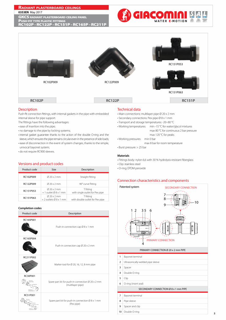
Technical data• Main connections: multilayer pipe Ø 20 x 2 mm• Secondary connections: Pex pipe Ø 8 x 1 mm• Transport and storage temperatures: -20÷80 °C• Working temperatures: min -15 °C for water/glycol mixtures
max 80 °C for continuous 2 bar pressure max 120 °C for peaks
• Working pressures: min 0 bar max 8 bar for room temperature
DescriptionPush-fit connection fittings, with internal gaskets in the pipe with embedded internal sleeve for pipe support.The fittings have the following advantages:• ease of insertion into the pipe;• no damage to the pipe by locking systems;• internal gasket guarantee thanks to the action of the double O-ring and the sleeve, which ensures the pipe remains circular even in the presence of side loads;
• ease of disconnection in the event of system changes, thanks to the simple, univocal bayonet system;
• do not require RC900 sleeves.
Versions and product codesProduct code Size Description
RC102P009 Ø 20 x 2 mm Straight fitting
RC122P009 Ø 20 x 2 mm 90° curve fitting
RC151P053 Ø 20 x 2 mm+ 1 outlet Ø 8 x 1 mm
T fittingwith single outlet for Pex pipe
RC151P063 Ø 20 x 2 mm+ 2 outlets Ø 8 x 1 mm
T fittingwith double outlet for Pex pipe
Completion codes
Product code Description
RC165P001
Push-in connection cap Ø 8 x 1 mm
RC165P004
Push-in connection cap Ø 20 x 2 mm
RC211P002
Marker tool for Ø 20, 16, 12, 8 mm pipe
RC30P001
BOCCOLACON O-RING
PINZETTA
TERMINALECON BAIONETTA
Spare part kit for push-in connection Ø 20 x 2 mm(multilayer pipe)
RC51P001BOCCOLACON O-RING
PINZETTA
DISTANZIALE
DOPPIO O-RING
TERMINALECON BAIONETTA
Spare part kit for push-in connection Ø 8 x 1 mm(Pex pipe)
Pipe disconnection1) Rotate the bayonet terminal anti-clockwise using the relevant wrench.
2) Disconnect the bayonet terminal.
3) Remove the clip from the pipe using cutters.
4) Insert the replacement RC30P001 kit into the body, in the following order:• insert with O-ring lubricated with silicone grease;• stainless steel clip, with its teeth bent towards the body.
INSERT WITHO-RING
CLIP
BAYONET TERMINAL
5) Reconnect the bayonet terminal, rotating it clockwise using the relevant wrench.
Warning.Fittings must be disassembled for disconnection purposes only by trained personnel.
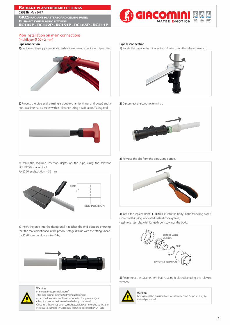
Pipe installation on main connections(multilayer Ø 20 x 2 mm)Pipe connection1) Cut the multilayer pipe perpendicularly to its axis using a dedicated pipe cutter.
2) Process the pipe end, creating a double chamfer (inner and outer) and a non-oval internal diameter within tolerance using a calibration/flaring tool.
3) Mark the required insertion depth on the pipe using the relevant RC211P002 marker tool.For Ø 20: end position = 39 mm
END POSITION
PIPE
4) Insert the pipe into the fitting until it reaches the end position, ensuring that the mark mentioned in the previous stage is flush with the fitting's head.For Ø 20: insertion force = 6÷16 kg
Warning.Immediately stop installation if:• the pipe cannot be inserted without forcing it• insertion forces are not those included in the given ranges• the pipe cannot be inserted to the length requiredOnce installation has been completed, it is recommended to test the system as described in Giacomini technical specification 0415EN.
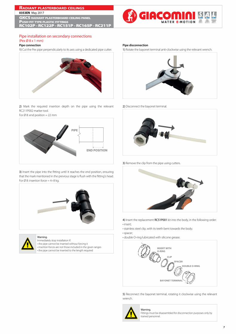
Pipe disconnection1) Rotate the bayonet terminal anti-clockwise using the relevant wrench.
2) Disconnect the bayonet terminal.
3) Remove the clip from the pipe using cutters.
4) Insert the replacement RC51P001 kit into the body, in the following order:• insert;• stainless steel clip, with its teeth bent towards the body;• spacer;• double O-ring lubricated with silicone grease.
INSERT WITHO-RING
CLIP
SPACER
DOUBLE O-RING
BAYONET TERMINAL
5) Reconnect the bayonet terminal, rotating it clockwise using the relevant wrench.
Warning.Fittings must be disassembled for disconnection purposes only by trained personnel.
Pipe installation on secondary connections(Pex Ø 8 x 1 mm)Pipe connection1) Cut the Pex pipe perpendicularly to its axis using a dedicated pipe cutter.
2) Mark the required insertion depth on the pipe using the relevant RC211P002 marker tool.For Ø 8: end position = 22 mm
END POSITION
PIPE
3) Insert the pipe into the fitting until it reaches the end position, ensuring that the mark mentioned in the previous stage is flush with the fitting's head.For Ø 8: insertion force = 4÷8 kg.
Warning.Immediately stop installation if:• the pipe cannot be inserted without forcing it• insertion forces are not those included in the given ranges• the pipe cannot be inserted to the length required
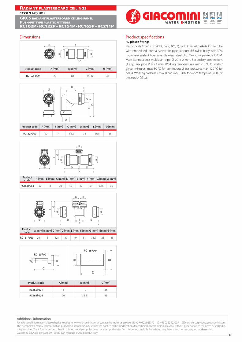
Product specificationsRC plastic fittingsPlastic push fittings (straight, bent, 90°, T), with internal gaskets in the tube with embedded internal sleeve for pipe support. 6,6 nylon body with 30% hydrolysis-resistant fiberglass. Stainless steel clip. O-ring in peroxide EPDM. Main connections: multilayer pipe Ø 20 x 2 mm. Secondary connections (if any): Pex pipe Ø 8 x 1 mm. Working temperatures: min -15 °C for water/glycol mixtures; max 80 °C for continuous 2 bar pressure; max 120 °C for peaks. Working pressures: min. 0 bar; max. 8 bar for room temperature. Burst pressure > 25 bar.
Dimensions
BØ
CA A
Product code A [mm] B [mm] C [mm] Ø [mm]
RC102P009 20 88 ch. 30 35
CB
ØE
D
A
A
Product code A [mm] B [mm] C [mm] D [mm] E [mm] Ø [mm]
RC122P009 20 74 56,5 74 56,5 35
GF
Ø D EC
AA
B
Product code A [mm] B [mm] C [mm] D [mm] E [mm] F [mm] G [mm] Ø [mm]
RC151P053 20 8 98 49 49 51 33,5 35
GA A
F
DØ EI
B B
C
Product code A [mm] B [mm] C [mm] D [mm] E [mm] F [mm] G [mm] I [mm] Ø [mm]
RC151P063 20 8 121 49 49 51 33,5 23 35
RC165P001
C
BA
RC165P004
BA
C
Product code A [mm] B [mm] C [mm]
RC165P001 8 19 35
RC165P004 20 35,5 45
Additional informationFor additional information please check the website: www.giacomini.com or contact the technical service: ' +39 0322 923372 6 +39 0322 923255 * [email protected] pamphlet is merely for information purposes. Giacomini S.p.A. retains the right to make modifications for technical or commercial reasons, without prior notice, to the items described in this pamphlet. The information described in this technical pamphlet does not exempt the user from following carefully the existing regulations and norms on good workmanship. Giacomini S.p.A. Via per Alzo, 39 - 28017 San Maurizio d’Opaglio (NO) Italy


![OPOTEK.COM • 760.929e n e rg y [m j] wavelength [nm] radiant x30 series opo output radiant nx9130 radiant qx8130 radiant nx6130 radiant qx4130 0 4 8 12 16 20 200 220 240 260 280](https://static.documents.pub/doc/80x56/60dc720ce9b2c615fe7d6fd3/a-760929-e-n-e-rg-y-m-j-wavelength-nm-radiant-x30-series-opo-output-radiant.jpg)


