Radiation-Hard/High-Speed Data Transmission Using Optical Links. Richard Kass The Ohio State University. W. Fernando, K.K. Gan, A. Law, H.P. Kagan, R.D. Kass, J. Moore, D. S. Smith The Ohio State University. OUTLINE Introduction-ATLAS/Pixel Detector/SuperLHC System Architecture-issues - PowerPoint PPT Presentation
16
R. Kass N64-4 1 IEEE08/NSS Radiation-Hard/High-Speed Data Transmission Using Optical Links rnando, K.K. Gan, A. Law, H.P. Kagan, R.D. Kass, J. Moore, D. S. Sm The Ohio State University Richard Kass The Ohio State University OUTLINE Introduction-ATLAS/Pixel Detector/SuperLHC System Architecture-issues 0.13 μm opto-chip prototype Summary
Transcript
R. Kass N64-4 1IEEE08/NSS
Radiation-Hard/High-Speed Data Transmission Using Optical Links
W. Fernando, K.K. Gan, A. Law, H.P. Kagan, R.D. Kass, J. Moore, D. S. SmithThe Ohio State University
Richard KassThe Ohio State University
OUTLINEIntroduction-ATLAS/Pixel Detector/SuperLHC
System Architecture-issues 0.13 μm opto-chip prototype
Summary
R. Kass N64-4 2IEEE08/NSS
The Current ATLAS Pixel Detector
A pixel module contains:1 sensor (2x6cm) ~40000 pixels
16 front end (FE) chips 2x8 array
Flex-hybrid1 module control chip (MCC)There are ~1744 modules~1.85m
Pixel Detector:ATLAS’s Inner most charged particle tracker Measures (x,y,z) to ~30 mPixel detector is based on silicon Pixel size 50m by 400 m ~80 million pixelsRadiation hardness is an issue must last ~ 10 years
ATLAS is a detector at CERN designed to study 14 TeV pp collisions Detector upgrade planned for Super-LHC in 2016
R. Kass N64-4 3IEEE08/NSS
Present Pixel Opto-link ArchitectureCurrent optical link of pixel detector transmits signals at 80 Mb/sOpto-link separated from FE modules by ~1m
transmit control & data signals (LVDS) to/from modules on micro twisted pairs
Use PIN/VCSEL arrays
Use 8 m of rad-hard/low-bandwidth SIMM fiber fusionspliced to 70 m rad-tolerant/medium-bandwidth GRIN fiber Simplify opto-board and FE module production Sensitive optical components see lower radiation level than modules PIN/VCSEL arrays allow use of robust ribbon fiber
R&D Issues for Super-LHCRadiation hardness of all components PIN array VCSEL arrays Opto-board ASICs: VDC, Receiver (replace DORIC)
SI (PIN) @ SLHC (3000fb-1)1.5 x 10¹⁵ 1-MeV neq/cm2
2.6 x 10¹⁵ p/cm2 or “69 Mrad” for 24 GeV protons GaAs (VCSEL) @ SLHC (3000fb-1)
8.2 x 10¹⁵ 1-MeV neq/cm2
1.6 x 10¹⁵ p/cm2 or “34 Mrad” for 24 GeV protonsIncreased speed of componentsReceiver: 160Mb/s or 320Mb/sVDC: 3.2Gb/sClock multiplier: generates fast clock for 3.2Gb/s serializer
R. Kass N64-4 6IEEE08/NSS
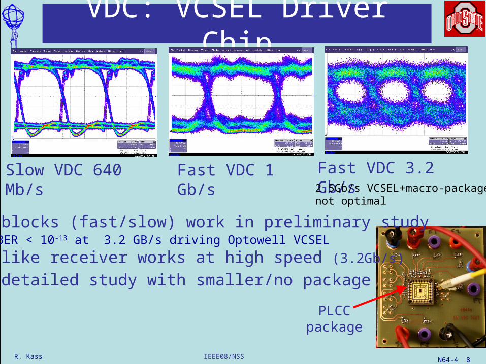
640 Mb/s VCSEL Driver
3.2 Gb/s VCSEL Driver
640 MHz clock multipliers(4 x 160 and 16 x 40 MHz)
PIN receiver/decoder(40, 160, 320 MHz)
Designed with 0.13μm process
Opto-Chip Prototype
1.5 mm x 2.6 mm
R. Kass N64-4 7IEEE08/NSS
Testing the 0.13um Opto-Chips
Use CERN’sT-7 beamline, 24 GeV protons to test:
Chips were tested in our lab at OSU Chips were irradiated to SLHC dose at CERN
LVDS-like output has good amplitude and baseline Amplitude 475mV, baseline=0.625V rise/fall time 125 ps
No significant degradation after irradiation to SLHC dose
BER Threshold
40 Mb/s BER threshold for 1 bit error/s
PIN Receiver/Decoder Chip
Peak to Peak thresholdssupply current @1.5V
R. Kass N64-4 11IEEE08/NSS
Clock MultiplierNeed to multiply recovered clock 160MHz/40MHz up to 640MHz for serialization.Both 4x and 16x clock multipliers workLow Clock jitter < 8 ps (0.5%)No change in current consumption after irradiation BUT: Two of the four chips lost lock during irradiation & needed power cycling to resume operation at 640 MHz Could not reproduce this behavior at OSU on test bench
R. Kass N64-4 12IEEE08/NSS
Summary
First 0.13μm chip submission mostly successful Full characterization of pre/post irradiation in progress Waiting for the chips to “cool off” so they can be shipped from CERN to OSU Aim for next chip submission in winter 2009 Will irradiate the chips at CERN, summer 2009
R. Kass N64-4 13IEEE08/NSS
extra slides
R. Kass N64-4 14IEEE08/NSS
Setup for Irradiation in Shuttle at CERN
Opto-boards
Rad hard optical fibers
25 meter optical fiber
Remotely moves in/out of beam
CERN T7 CERN T7
R. Kass N64-4 15IEEE08/NSS
Radiation-Hardness of PINGb/s Responsivity (A/W)
GaAs Pre Post
ULM 4.25 0.50 0.13
AOC 2.5 0.60 0.19
Optowell 3.125 0.60 0.25
Hamamatsu G8921 2.5 0.50 0.32
Si
Taiwan 1.0 0.55 0.33
Hamamatsu S5973 1.0 0.47 0.37
Hamamatsu S9055 1.5/2.0 0.25 0.21
R. Kass N64-4 16IEEE08/NSS
Real Time Monitoring in T7 Beam TestReal time testing of opto-board system using loop-back setup
dataDORIC
clockPIN
VDCVCSEL
Opto-board
VDCVCSEL
bi-phase marked optical signal
decoded data
decoded clock
Signal routed back to opto-baord via test board
attached to 80-pin connector & test board
Bit error test setupat CERN’sT-7 beamline24 GeV protons