1 Abstract—In the digital era, fifty-eight percent of women opt a HDTV (high-definition television) set over a one-carat diamond ring. Though the Consumer Electronics Association (CEA) released this result of survey in the end of 2002, it is still convincing just now. In the meantime, people who embracing the stunning viewing screens may have good possibility of exposing themselves to radiation hazards without perception. Index Terms—Electromagnetic radiation, biological effects of electromagnetic radiation, public safety, occupational health and safety. I. FOREWORD ORLDWIDE, the cutting-edge consumer electronics market is quickly altering from monotonous cathode ray tube (CRT)-based televisions to a wide variety of options. This change has been driven by the rapid adoption rate of DVD player in home theater systems and the rush of superior quality television technologies. You may probably heard tons about DTV or HDTV whether you are a television buff or not. HDTV is one type of DTV transmission. Currently, it is the most robust and detailed TV image you can have, its lifelike picture and sound that surpass DVD quality. The original impetus for HDTV came from wide-screen movies. Movie producers discovered that individuals seated in the first few rows enjoyed a level of participation in the action. Evidently, having the screen occupy a great field of view significantly increases the sense of “being there”. This unceasing fever of HDTV has spurred customers to seek televisions equipped with charming halo. Excelling the customary CRT-based rear projection televisions (RPTVs), the microdisplay-based RPTVs are gaining the market share forthwith in response to customer demand for ever topnotch picture quality, lager field of vision, smaller form factor and more affordable price points. II. MICRODISPLAY PROJECTION TECHNOLOGIES The proliferation of microdisplay projection technologies has taking over the floor space at the most electronics stores and the trend shows no signs of slowing down. They can be best divided by how they steer the light. Two major categories include those that shine the light through panels which either block or transmit light to create an image (transmissive) such as amorphous LCD (AM-LCD) and high-temperature polysilicon LCD (HTPS-LCD), and those that reflect the light off of a surface like a mirror (reflective) like Texas Instruments’ digital light processing (DLP™) and liquid crystal on silicon (LCoS). They essentially consist of a lamp that bounces light off of or through a tiny pixel-filled microchip and onto a big screen. The following block diagram reveals the key components and the formation of a projected image. To continue from the preceding paragraph, the form factor of CRT-based RPTV sets is demanded by the fairly bulky projection CRT itself and takes into account the size and weight of the three CRTs. Maybe a front projector is more persuasive in addressing this excellence, Mitsubishi had lunched the Mini DLP PocketProjector™ few months ago and it seems to realize the dream of projection anywhere. Mitsubishi Launches Mini LED DLP PocketProjector™ on Feb. 8th, 2005 Digital Light Processing (DLP™) is a display technology invented in 1987 by Dr. Hornbeck of Texas Instruments Inc. DLP imaging systems employ either one or three large (large for electronic chips) devices called Digital Micromirror Devices, or DMDs. The micromirrors are mounted on the DMD chip and tilt in response to an electrical signal; they are capable of switching on and off more than 1,000 times a second. The tilt directs light toward the screen (ON), or into a "light trap" (OFF) that eliminates unwanted light when reproducing blacks and shadows. The grayscale image is consists of up to 1,024 shades of gray. The color wheel filters the light into red, green, and blue images at different times, and the observer’s brain will recombine them into a single, full-color image. This is called “field sequential” color. DLP projection system can create at Radiation Hazards in the Great Technology War Flore Chiang, Member, IEEE W
Transcript
1
Abstract—In the digital era, fifty-eight percent of women opt
a HDTV (high-definition television) set over a one-carat diamond ring. Though the Consumer Electronics Association (CEA) released this result of survey in the end of 2002, it is still convincing just now. In the meantime, people who embracing the stunning viewing screens may have good possibility of exposing themselves to radiation hazards without perception.
Index Terms—Electromagnetic radiation, biological effects of electromagnetic radiation, public safety, occupational health and safety.
I. FOREWORD ORLDWIDE, the cutting-edge consumer electronics market is quickly altering from monotonous cathode
ray tube (CRT)-based televisions to a wide variety of options. This change has been driven by the rapid adoption rate of DVD player in home theater systems and the rush of superior quality television technologies. You may probably heard tons about DTV or HDTV whether you are a television buff or not. HDTV is one type of DTV transmission. Currently, it is the most robust and detailed TV image you can have, its lifelike picture and sound that surpass DVD quality. The original impetus for HDTV came from wide-screen movies. Movie producers discovered that individuals seated in the first few rows enjoyed a level of participation in the action. Evidently, having the screen occupy a great field of view significantly increases the sense of “being there”.
This unceasing fever of HDTV has spurred customers to seek televisions equipped with charming halo. Excelling the customary CRT-based rear projection televisions (RPTVs), the microdisplay-based RPTVs are gaining the market share forthwith in response to customer demand for ever topnotch picture quality, lager field of vision, smaller form factor and more affordable price points.
II. MICRODISPLAY PROJECTION TECHNOLOGIES The proliferation of microdisplay projection technologies
has taking over the floor space at the most electronics stores and the trend shows no signs of slowing down. They can be best divided by how they steer the light. Two major categories include those that shine the light through panels which either block or transmit light to create an image (transmissive) such as amorphous LCD (AM-LCD) and high-temperature polysilicon LCD (HTPS-LCD), and those that reflect the light off of a surface like a mirror (reflective) like Texas Instruments’ digital light processing (DLP™) and
liquid crystal on silicon (LCoS). They essentially consist of a lamp that bounces light off of or through a tiny pixel-filled microchip and onto a big screen. The following block diagram reveals the key components and the formation of a projected image.
To continue from the preceding paragraph, the form factor
of CRT-based RPTV sets is demanded by the fairly bulky projection CRT itself and takes into account the size and weight of the three CRTs. Maybe a front projector is more persuasive in addressing this excellence, Mitsubishi had lunched the Mini DLP PocketProjector™ few months ago and it seems to realize the dream of projection anywhere.
Mitsubishi Launches Mini LED DLP PocketProjector™ on Feb. 8th, 2005
Digital Light Processing (DLP™) is a display technology invented in 1987 by Dr. Hornbeck of Texas Instruments Inc. DLP imaging systems employ either one or three large (large for electronic chips) devices called Digital Micromirror Devices, or DMDs. The micromirrors are mounted on the DMD chip and tilt in response to an electrical signal; they are capable of switching on and off more than 1,000 times a second. The tilt directs light toward the screen (ON), or into a "light trap" (OFF) that eliminates unwanted light when reproducing blacks and shadows. The grayscale image is consists of up to 1,024 shades of gray.
The color wheel filters the light into red, green, and blue images at different times, and the observer’s brain will recombine them into a single, full-color image. This is called “field sequential” color. DLP projection system can create at
Radiation Hazards in the Great Technology War Flore Chiang, Member, IEEE
W
2
least 16.7 million colors for single-chip system and no fewer than 35 trillion colors for 3-chips system.
Courtesy of http://www.avdeals.com/classroom/what_is_dlp.htm
Most LCD projectors use high-temperature polysilicon technology. Unlike comparatively inexpensive LCD panels used in notebook display or desktop monitor, the wafers are fabricated from a pure silicon crystal as same as CPUs and memory chips or small silicon crystal crystallized from special glass or quartz substrate. This enables the higher electron mobility, the smaller switching transistors at each cell; the more light gets through and the brighter output luminance. Farther, some manufacturers (e.g. Epson) attach a carefully-aligned layer of tiny microlenses to the back of each panel to improve the transmittance.
This tiny LCD panels are made with one liquid crystal cell per pixel, three separate panels are used to create images for red, green, and blue colors, and then the images are optically combined and projected onto the screen. The keys to making this work are dichroic mirrors and prisms. “Dichroic” means that the material has or shows two colors. They are also known as beam splitters.
Courtesy of http://www.3lcd.com/eg/ftr_ts_e.html
III. ADVANCES IN LIGHT SOURCE The photons (light particles) are notoriously difficult to
grip. One key element of controlling the light beam is to reduce the size of the light source. The ideal source would be infinitely small without any loss of brightness, or luminance (the amount of light produced). Unfortunately, practice can't measure up to theory. If your source is bigger than a single point, not all the beams originate exactly at the focus and they are possibly missing the other focus point. Farther, the wider the ellipse – meaning a greater distance between the two focus point, then the beam spot will be at second focus. Projector engineers spend a lot of time struggling with the light sources.
In early stages, most projectors relied upon metal halide lamps that offer very high efficacy and high-quality light. However, they have some drawbacks such as considerable amounts of time taken in start-up and restarting after a shutdown or power interruption (improvable by pulse-start system) and they also tend to deposit materials such as tungsten on the walls of the lamp during operation, resulting in reduced brightness starting early in the useful life.
Now, high-pressure mercury lamps are broadly used as the light source in microdisplay-based RPTVs. The last major innovation occurred in 1998 with the invention of UHPTM (Ultra-High Performance) lamps by Hanns Fischer (Philips Research). These new sources operated with an internal pressure of about 200 atmospheres, consequently leading to a strong continuum in the emission spectrum and a high arc power loading. The shorter arc technologies (from 1.3 mm arc size to 1.0 mm) creating a much smaller light source and much greater lighting efficacy – a 100 watt UHP lamp in a projector can deliver more light to the screen than a 250 watt metal halide lamp.
The lamp system is an amazing artifact that comprises many complex technologies in various fields; it must be handled with special cares such as: Both metal halide and mercury vapor lamps tend to emit
annoying high-levels of UVR that can damage sensitive fabrics, papers, artifacts and even mankind if not effectively attenuated or shielded.
The lamp compartment must be ventilated thoroughly since the photolysis of oxygen may generate ozone when operating the lamp in an oxygenic atmosphere (in the air). The excessive inhalation of ozone could cause discomfort like headaches, nausea or dizziness.
Farther, the risk of lamp shatter (e.g. incurred by splash or collision) amplified by intense ratio of atmospheric pressures shall be considered. This may be safeguarded by limited accessibility.
The lamps cannot be thrown in the trash if they are found to carry hazardous waste. It is the responsibility of waste generator to insure proper classification of waste products. To the end, the TLCP (Toxicity Characteristic Leaching Procedure) shall be conducted to determine the ultimate disposition. Disposal of spent lamps must be in accordance with applicable federal, state and local regulations.
IV. THE NATURE OF ULTRAVIOLET RADIATION The radiant energy which radiates through space in all
directions is called “electromagnetic” since it comprises oscillating electric and magnetic fields. Electromagnetic radiation tends to exhibit particle-like properties at X-ray or shorter wavelength, whereas toward the long wavelength it behaves mostly wave-like. Ultraviolet radiation (frequently abbreviated as UVR) falls into the region of non-ionizing electromagnetic spectrum whose frequency less than 2.42e+15 Hz. Unlike the ionizing radiation, non-ionizing
3
radiation dose not has sufficient energy to knock out the electron from the orbit – ionize atomic oxygen and hydrogen. Non-ionizing radiation appears relatively low energy and causes atomic excitation only. Consequently the biological effects were limited to skin and eyes, tissues at depth are unlikely to be at risk. UVR is considered as inconspicuous hazard since the generic public could not consciously recognize the danger by the sense of sight.
Courtesy of http://newark.rutgers.edu/~huskey/images/em_radiation.jpg
UVR spans the wavelengths from 100 to 400 nm. The biological effects of UVR are much wavelength dependent. By convention and phenomenological basis, the ultraviolet spectrum has been further subdivided into three regions: UVC, UVB and UVA.
TABLE 1 – Ultraviolet Radiation Wavelength Regions
Region CIE Divisions (nm) ICNIRP/IEC/ACGIH Divisions (nm)
Ultraviolet C (UVC) 100 – 280 180 – 280 Ultraviolet B (UVB) 280 – 315 280 – 315 Ultraviolet A (UVA) 315 – 400 315 – 400 The differences among different parties were printed in italics
The sunlight is the most common experience of exposure to UVR, and the sun remains the most general source of radiant energy as well. In an ordinary cloudless day, all UVC and approximately 90% of UVB radiation are absorbed by ozone, water vapour, oxygen and carbon dioxide. However, UVA is less affected by the atmosphere. The ozone layer of stratosphere plays an important role in UVR absorption. In studies over two decades, air pollution, especially carbon dioxide, had formed a large lens like an atmosphere insulator constituting the “greenhouse effect” that had gradually warming up the earth year after year.
Before the beginning of this century, the sun was essential the only source of UVR, but the opportunity for additional exposure has increased with the advent of artificial sources. Most man-made sources of UVR can be clustered together in the categories as below:
TABLE 2 – Conventional Artificial UVR Sources
Source Type Sub-group Example(s) Inherently safe?
Tungsten General, display and emergency lighting
Yes Incandescent
Tungsten halogen
Spotlights, heating and floodlighting No
Solid state lamps
LEDs, electro-luminescent lamps
Display, panel indicators, night lights
Yes
Electric discharges Open arcs Welding arcs No
Low pressure Na
General and industrial lighting Yes
Low pressure Hg
General lighting horticultural and germicidal, sunbeds
No
UVA black light Hg
Fluorescence, medical Yes
High pressure Na Floodlighting Yes
High pressure Hg
Industrial, printing, curing commercial lighting
No
Special High Intensity Discharge (HID)
Polymerisation reprography No
High pressure Hg/Xe
Photochemical and projection No
Xe Projection and photography No
Gaseous discharges
Pulsed Xe Printing No
The health effects from excessive exposure to UVR are the same between artificial and solar UVR. However, as some artificial sources can emit more of hazardous narrow-band UVR wavelengths and greater intensive, the time required to reach the threshold might be tremendously squeezed.
V. KNOWN BIOLOGICAL EFFECTS Since the ancient times, the danger of ultraviolet radiation
have been firstly known as the Greek philosopher Xenophen mentions “snowblindness” in his treatise, Anabasis. UVR is not detected by the visual receptors in the human eyes. Accordingly, ocular damage could occur without the person being aware of the danger.
UVR with wavelengths from 10 nm to 180 nm are sometimes referred as vacuum or extreme UV, it is not easily transmitted through air and usually exists only in vacuum. The UVC band extends into the vacuum UV does not need to be considered since we do not live under such conditions.
Short wavelength UVC is almost completely absorbed in stratosphere within few hundred meters. When UVC photons collide with oxygen atoms, the photolysis of oxygen impels the formation of ozone. Artificial germicidal UVC lamps are frequently used to purify air and water upon their ability to kill bacteria. In humans, UVC is absorbed in the outer “dead” layers of the skin (opposite to inner “live” layers, the dead layers include the surface scale, outside hair and exposed nail plate). Accidental exposure can cause server sunburn to the face or inflammation of the cornea (photo keratitis) and conjunctiva (photo conjunctivitis). The later may result in the feeling of having sands in the eyes. However, new cornea and conjunctiva cells constantly
4
re-grow, the damage is reversible. The eyes heal themselves in one or two days after contracting the condition. Above damage is known as welder’s flash or snow blindness, they are fairly common.
Courtesy of http://library.thinkquest.org/J002508/eyeballs.htm
UVB is typically the most destructive form of UVR, since it has enough energy to cause photochemical damage to cellular DNA and is not entirely absorbed in the atmosphere. UVB incurs erythema (sunburn) and cataracts, and the development of skin cancer. The cataracts are referred to the process of clouding the lens. They can sharply impair the vision or even incur blindness if the process progresses unceasingly. Since lens tissue is dissimilar to other tissues in the body – does not grow new cell, the damage is irreversible. Current understanding and research have implicated UVB as a cause of certain types of skin cancer. DNA absorbs UVB and the absorbed energy can break bonds in the DNA. Proteins in the cell’s nucleus repair most of these breakages but the remained genetic damage can lead to skin cancer. Nonetheless, it appears in individuals whose skin is exposed to UVB (mostly solar radiation) for a significant period of time (years).
UVA, often referred as black light, as it can cause fluorescent materials to emit visible light – thus appearing to glow in the dark. Long wavelength UVA is the most commonly found type of UVR and is the least harmful. In the beginning, a pigment-darkening phenomenon incurs where the skin produces melanin to protect itself from exposure. This is followed by erythema if the overexposure. Moderate exposure to UVA is beneficial where a type of skin steroid (7-dehydrocholesterol) is converted to a form of vitamin D (an intermediate in cholesterol biosynthesis).
Special cares for certain individuals have abnormal skin responses to UVR exposure (i.e., photosensitivity) because of genetic, metabolic or other abnormalities, or show photosensitive responses because of intake or contact with certain drugs or chemicals. They may be less resistive than the normal.
Human body is a self-building machine, a self-stoking, self-regulating, self-repairing machine – the most marvelous and unique automatic mechanism in the universe, since the most ingenious machines set up by modern science can for a moment compare with it. The risk assessment shall be built upon the hazardous energy source that cannot cope anymore by the robust body or lead to irreversible adversities.
VI. GUIDELINES FOR EXPOSURE LIMITS
The intensity of UVR is often measured by the amount of energy deposited per unit area, irradiance (E) and radiant exposure (H). Irradiance (a dose rate used in photobiology) is described in watts (unit of power) per square meter (W m-2) or centimeter (W cm-2). Radiant exposure (H) is dose, and is described in joules (unit of energy) per square meter (J m-2) or centimeter (J m-2). Since a watt is a joule per second, thus, the dose rate multiplied by the exposure duration (seconds) equals to dose. A total dose value is obtained by integrating the dose rate over time. While scientifically this is easy to do in an experimental setting, it is not practical in real-life.
The critical organs for UVR exposure are the eye and skin. The biological effects vary tremendously with wavelength. Therefore, “action spectra” have been developed to create a dose-response relationship; it refers to the relative spectral effectiveness of different wavelength to elicit a biological effect. The result of the efficient UVR spectrum normalized to the action spectra forming an acceptable criterion.
ACGIH UV Relative Spectral Effectiveness
Relative Spectral Effectiveness of IEC TR 60825-9:1999
The limit value of 3.0 mJ cm-2 (30 J m-2) is based on the wavelength of 270 nm, where the eye tends to show the maximum sensitivity for acute effects on the cornea. Due to the eye becomes relatively insensitive at other wavelengths, the exposure limits change (increase) in response to the fact that it takes more dose elicit the same effects.
There has been much work to produce a basis to define a unified action spectrum in evaluating occupational exposure that would apply for both erythemic and keratotic effects. This greatly facilitates the field instrumentation – the reading can be proper weighted by a specially made optic filter that simulates the desired action spectrum.
The adjective “recommended”, indicates that we do not have a completely united specifications for body exposure to
5
ultraviolet radiation so far. They are roughly the same but they may be at odds in evaluating specific narrow-band light sources. Guidelines for exposure limits are usually of form of national regulations or international recommendations like: The American Conference of Governmental Industrial
Hygienists (ACGIH) has published a Threshold Limit Value (TLV) for occupational exposure to UVR.
The International Commission on Non-Ionizing Radiation Protection (ICNIRP) has published a series of exposure limits (ELs) for non-coherent optical radiation.
IEC TR 60825-9:1999 “Safety of Laser Products – Part 9: Compilation of maximum permissible exposure (MPE) to incoherent optical radiation” which has been prepared by IEC TC 76: Optical radiation safety and laser equipment. This Technical Report is purely informative and is not to be regarded as an International Standard. It reconciles current MPE values for incoherent optical radiation from artificial sources in the wavelength range from 180 nm to 3000 nm.
380 – 1400 50000/αt1/4 W m-2 sr-1 eff Retinal burn (visual stimulus & t < 10s)
380 – 1400 28000/αt1/4 W m-2 sr-1 eff Retinal burn (visual stimulus & t > 10s)
i) The wavelength is expressed in nanometer (nm), ii) The term “eff” is abbreviated from effective, and iii) The differences among different parties were printed in italics. In general, RPTVs are investigated by IEC 60950-1:2001
“Information Technology Equipment – Safety – Part 1: General Requirements” or IEC 60065-1:2001 “Audio, Video and Similar Electronic Apparatus – Safety Requirements”. The former adopted the limits given in IEC 60825-9 for an 8 h exposure (wavelength between 180-400 nm considered). Unfortunately, the later did not address UVR at all.
VII. UPDATE FROM IEC TC108 MT2
Lately, IEC TC 108 MT2 Interpretation Panel issued an interpretation on the present wording in IEC 60950-1:2001, 4.3.13 and 4.3.14 (Question No. 49) on April 29, 2005. The Interpretation Panel agrees to exempt products such as LCD projector (beamer) from the above-mentioned requirements since they did not emit predominant radiation in UVR region (180-400 nm). With the issuance, projection displays will no longer subject to UVR evaluation as the most light sources did not emit UVR “significantly” or “predominantly” in wavelengths between 180-400 nm.
This formal interpretation had greatly ceased the early debate on the applicability issue and clarified the opinion of the Panel. It seems somehow reasonable for only equipment designed to emit predominant UVR should be assessed for an 8-hour exposure, yet the determinative percentage is still suspended and need to be further settled. Moreover, the ceiling of body susceptibility had been discovered in form of absolute values (suitably weighted dose or dose rate) rather than spectral occupancy that may vary with extensive variety of the light source. The source can be dramatically hazardous if its emission spectrum shows too much similar to the action spectra even if the spectral occupancy is insignificant. The following section will attempt to talk over the necessity.
VIII. ESTIMATION OF UVR IRRADIANCE
Actually, UVR is “un-desired” energy in image projection. The critical performance factor “luminance” is referred as the brightness perceived by human eyes. Our eyes are designed to detect a small portion of the electromagnetic spectrum – visible light region which ranges in wavelengths from about 380/400 nm to 700/780 nm depending upon which source is used, and also depends on the sensitivity of a specific persons eyes. However, excessive UV and IR (Infrared, often referred as heat) may possibly damage the DMD chip in accordance with the recommendations specified by TI.
Table 4 – Recommended Operating Conditions Illumination, wavelength less than 400 nm Max. 0.68 mW cm-2
Illumination, wavelength greater than 800 nm Max. 10 mW cm-2
Courtesy of Texas Instruments Inc. As yet, light sources on earth are not an ideal point source.
The stray light (possibly accompanied with invisible UV and
6
IR) may become a big deal all around the light path. If the light did not thoroughly funneled through the optics, whether it strikes other surfaces where it should not or escapes from the openings, ends up reducing the brightness at the screen and overall contract (grays the solid black), and heating up the unit.
Therefore, all projector engineers eagerly hope that all light particles except for UV and IR, are left unharmed at the projection screen. Somehow, the projector engineers and safety engineers are aligned in a common end – to interpose safeguards against UVR. The following estimate is based upon primarily the principle of conservation of energy and many assumptions (especially the test data) that are helpful to reproduce a scene of investigation. The imaginary sample is a DLP-based RPTV employing a 120 W lamp, which emits UVA of 2.2 W, UVB no more than 0.1 W and UVC no more than 0.01 W.
The light particles’ journey to the screen starts right with the lamp, the reflector collects them onto the focus. In general, parabolic reflector is often used in LCD and LcoS system, and elliptical one is broadly found in DLP system. Before the photons enter the imaging engine, this stage is an opportunity to integrate them more evenly in desired shapes (e.g. an rectangular beam with equivalent brightness).
Illumination optics in different reflector type
The first safeguard is the plate UV-IR filter, which is made of special glass and located in front of the lamp. It is responsible for reject bands of UV and IR, and offers 99% decay of UVR. In fact, this filter will tilted at a certain angle to bring the UV and IR into a light trap (usually made of metal) rather than backward to the lamp unit. The primal concern is the unwanted energy will directly heat up the lamp and generate needless thermal burden.
Typical Transmittance of the Plate UV-IR Filter
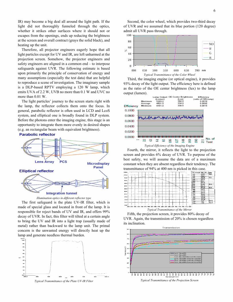
Second, the color wheel, which provides two-third decay of UVR and we assumed that its blue portion (120 degree) admit all UVR pass through.
Typical Transmittance of the Color Wheel
Third, the imaging engine (or optical engine), it provides 93% decay of the light output. The efficiency here is defined as the ratio of the OE center brightness (lux) to the lamp output (lumen).
Typical Efficiency of the Imaging Engine
Fourth, the mirror, it reflects the light to the projection screen and provides 6% decay of UVR. To purpose of the best safety, we will assume the data are of a maximum constant when they are absent regardless their tendency. The transmittance of 94% at 400 nm is picked in this case.
Typical Transmittance of the Mirror
Fifth, the projection screen, it provides 80% decay of UVR. Again, the transmission of 20% is chosen regardless its inclination.
Typical Transmittance of the Projection Screen
7
Eventually, the UVR irradiance at the projection screen without weighted (we assumed that the UVR was absorbed by the body completely regardless spectral effectiveness) could be roughly estimated by decays given above, it is:
Unlike the light path lead to the screen, the back of the
lamp – the reflector may be a problem if not proper coped. This time, the projector engineers and safety engineers are diverged from each other. The former tends to effectively ventilate the burning lamp compartment to obtain the lower thermal equilibrium. The later worries about the visible light leaks (possibly contain invisible radiation) from the openings could be at risk. Now we will proceed to next estimate.
The reflector plays the weightiest role in light conveying. It was skinned with a Taylor-made coating that on the one hand facilitates the reflector to gather all visible photons to the focus, and on the other let unwanted photons such as UVR or IR to pass through.
Reflectance of the Reflector Coating
Since the lamp cannot effectively lower its emission of UVR by solely itself, intervening an independent safeguard may be required. To this end, the lamp was usually enveloped in a housing to prohibit residual risks. Below spectrograph shows no response where wavelength less than about 800 nm, in the same manner, the last digit of data is ignored (equally tenfold). If the lamp compartment were carefully constructed, the housing would be greatly effective.
Transmittance of the Lamp Housing
The UVR irradiance at the lamp housing without weighted could be roughly estimated by decays given above, it is:
In the real world, energy is fading all the time in all apace
and conforms to the inverse square law (the proviso will be discussed later). Boldly speaking, safeguards (not only safety safeguard but also performance safeguard) are anywhere (e.g. distance, atmosphere) and only which offers significant decay or is of essential component was cited above.
IX. BEFITTING ASSESSMENT GUIDELINES
Prior to all, I’d like to introduce BS EN 14255-1:2005 “Measurement and Assessment of Personal Exposure to Incoherent Optical Radiation – Part 1: Ultraviolet Radiation Emitted by Artificial Sources in the Workplace” which is just published in March 2005. It establishes a notional flowchart of procedure that somehow rescues present shortage of uniform process for UVR exposure assessment. A general procedure was outlined a breakdown as below: a) Preliminary Review. To conduct a paper exercise and
determine whether a detailed hazard assessment based upon measurement is necessary or not.
b) Work Task Analysis. To determine the environmental condition and set the applicable exposure limits.
c) Measurement of UV-exposure. It also gives the criterion for uncertainty.
d) Assessment of UV-exposure. To compare with the limit and classify whether hazardous or not.
e) Decision about Protective Measures. To determine that whether the safeguard is necessary or not, then return to the step of c) where needed.
f) Decision about a Repetition of the Measurement and Assessment.
g) Preparation of a Report. If a clear statement can be made that personal UVR
exposure is insignificant and that exposure limit values will be met, no further action is necessary and steps b) through e) need not be applied.
To carry out a full set of radiometric hazard assessment of the complete range of sources available in any particular application would require considerable equipment, expertise and time, and therefore would never be inexpensive. If adequate and precise UVR emission data are available for device under investigation, the bulky measurement might consider be waiving or limiting as minimum.
Where the test is necessary, the following precautions are highly recommended to take: The test shall be conducted in where free from stray
light and reflections. The device under test shall be operated at its maximum
UVR irradiance and removed all user removable parts or user serviceable parts which in the absence of safety
8
interlock system. The hot spot where at the highest level of the effective
irradiance is determined by placing the detector on the surface where user can gain access. This is arguable because most of them are not of intended usage, and specifying definable duration may solve it.
The inverse square law may be usable to compute the irradiance at a distance. As a crude rule of thumb, the distance between detector and source should be at least ten times the largest geometric dimension of the source such that the error can be exactly 1%.
Where the safety interlock system is employed, it shall be evaluated in accordance with IEC 60950-1, 2.8, such as inadvertent re-activation and durability.
The measurement instrument shall right calibrated and traceable to national and international institutes.
For measurement of irradiance or radiant exposures, there are two common methods often seen but are quite different – static scanning spectroradiometer and radiometer with spectral sensitivity according to specified weighting function. The former is the singular way to provide whole spectral information, but some flaws due to the spectroradiometers are highly sophisticated optical measurement devices, and in general, their proper calibration, operation and maintenance is rather time consuming and costly. The later is exactly the best choice for vast majority of applications, which offers economical and user-friendly alternative. Its advantages are direct reading, inexpensive, portable and quick, but the uncertainty may be large if insufficient matching to certain predefined spectral sensitivity function.
X. SUMMARY
Today’s market reveals its need for sound and uniform safety assessment. Many high-end projectors (theater-quality or conference-purpose) with dazzlingly brightness rush into the market, the ANSI lumen output may range from 3000 up to 12000. With the demanding for higher brightness and more compact size, the lamp becomes smaller but brighter, as well as the housing getting highly perforated. It can be risky if we do not cope this trend well.
Compare with the slight exposure limit (0.1µW cm-2), it is easily to stride over if not efficient safeguarded. To the best safety, the acceptance should rather rely upon the detailed process of risk assessment than grouping specific product type. Nominal boundary is no longer guarantee to hold safe.
The estimate is conformed to the philosophy of the HBSE and the principle of conservation of energy. And it had been testified by later measurement, the hot spot is located on the screen (0.009 µW cm-2), the maximum irradiance is below and distant about one order from the criterion. But this individual incident is upon case-case basis and is intended for reference only, and it should not serve as a warranty of safety.
Why almost exposure guidelines are originally for
workers and employees? On their premise, employees will still have UVR exposure regardless whether they want to make use of UVR sources or not. Users are considered unlikely to give rise to exposures in excess of the limits if they can recognize the danger. The later is very helpful in hazard assessment.
Second, why the limits adopt 8 hours exposure per day for users using information technology equipment? Frankly, I don’t know. American adults spent average 4 hours watching TV per day, no one force them to do this. This major conflict just makes the best interpretation to “occupational” exposure. Therefore, behavioral safeguard or personal avoidance may greatly helps to free the user from harm. Raising the public awareness of the imperceptible hazard needs to be highly progressed maybe as well as the great technology. Perhaps the 8 hours exposure could be halved or less upon above or limiting the operation duration.
Needless to say, manufacturers have responsibilities to consider all potential sources of exposure in use. If all lamp units, lamp systems and end products were uniformly classified by radiometric measurement prior to place on the market, most hazard assessments would be reduced to a paper exercise in administrative review. For the most part, manufacturer’s spectroradiometric classification data would greatly simplify matters.
REFERENCES [1] Tom Butts, “Women Opt for Technology Products over Diamonds,
Says New CEA Survey”, HDTelevision News, Apr. 08, 2004. [2] Alfred Poor, “Projection Display Technology”, ExtremeTech
Headlines, Oct. 05, 2001. [3] Dr. Donald G. Pitts, “Ultraviolet Radiation and How to Protect the Eye