64
Radiation Thermometry P M V Subbarao Professor Mechanical Engineering Department Non-intrusive Methods of Temperature Measurement
Radiation Thermometry
P M V SubbaraoProfessor
Mechanical Engineering Department
Non-intrusive Methods of Temperature Measurement
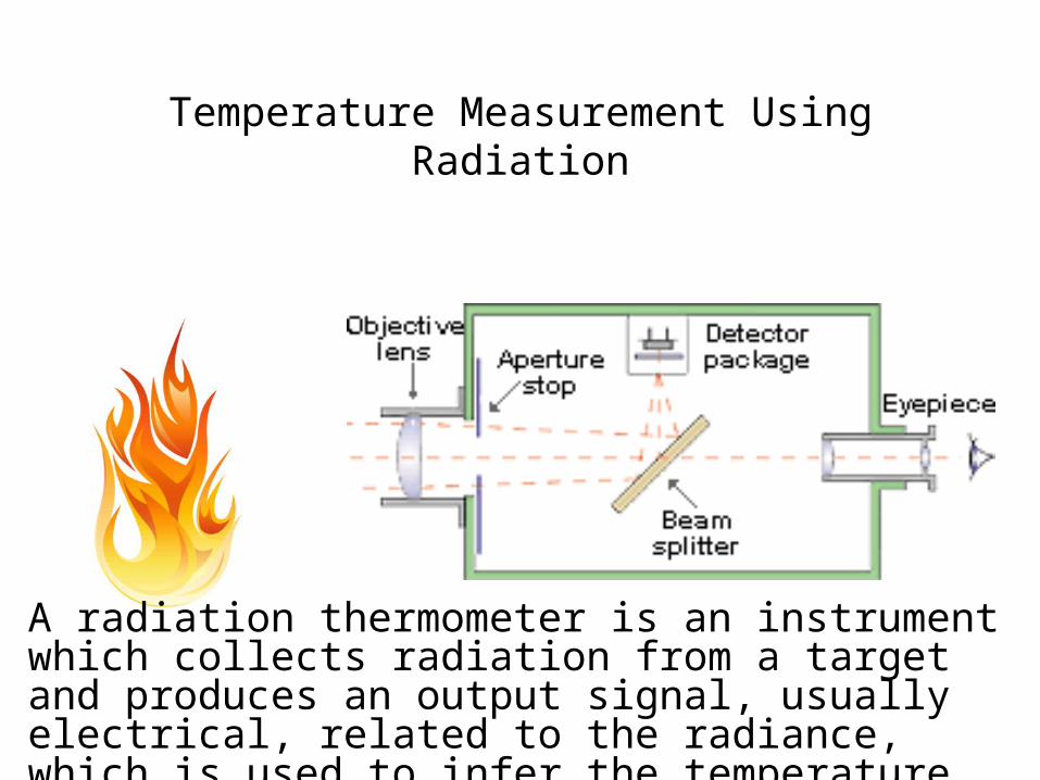
Temperature Measurement Using Radiation
A radiation thermometer is an instrument which collects radiation from a target and produces an output signal, usually electrical, related to the radiance, which is used to infer the temperature of the target.
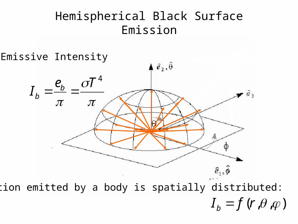
Hemispherical Black Surface Emission
4TeI b
b
Emissive Intensity
The radiation emitted by a body is spatially distributed:
),,( rfIb
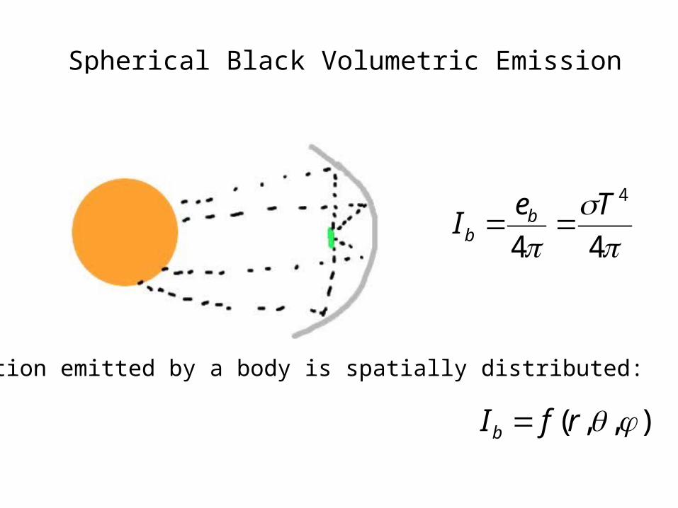
Spherical Black Volumetric Emission
44
4TeI b
b
The radiation emitted by a body is spatially distributed:
),,( rfIb
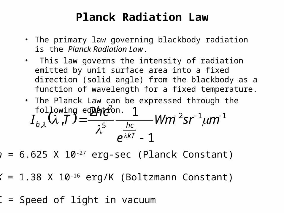
Planck Radiation Law
• The primary law governing blackbody radiation is the Planck Radiation Law.
• This law governs the intensity of radiation emitted by unit surface area into a fixed direction (solid angle) from the blackbody as a function of wavelength for a fixed temperature.
• The Planck Law can be expressed through the following equation.
1125
2
,
1
12,
msrWm
e
hcTI
kT
hcb
h = 6.625 X 10⁻²⁷ erg-sec (Planck Constant)
K = 1.38 X 10⁻¹⁶ erg/K (Boltzmann Constant)
C = Speed of light in vacuum
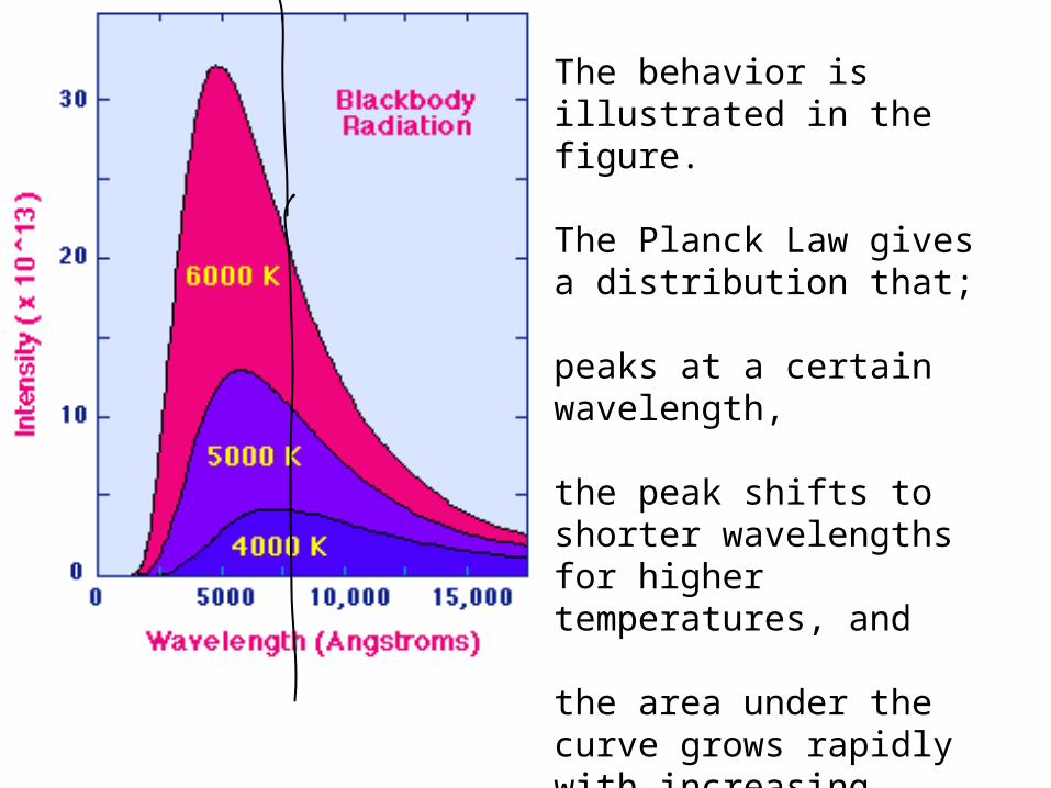
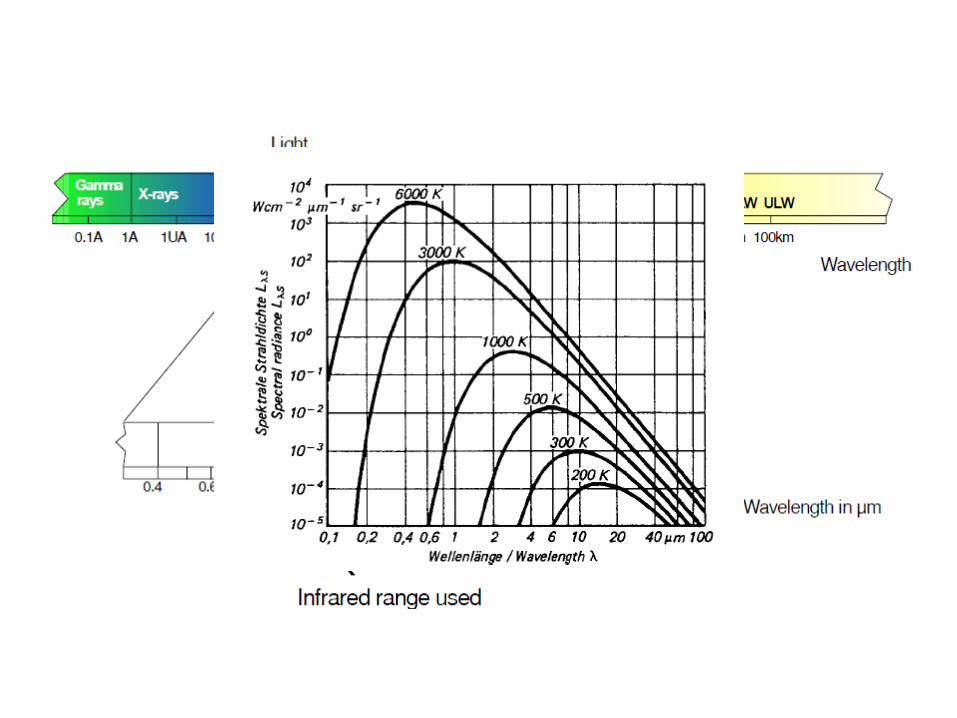
The behavior is illustrated in the figure.
The Planck Law gives a distribution that;
peaks at a certain wavelength,
the peak shifts to shorter wavelengths for higher temperatures, and
the area under the curve grows rapidly with increasing temperature.
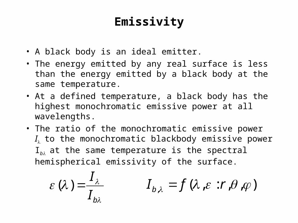
Emissivity
• A black body is an ideal emitter.
• The energy emitted by any real surface is less than the energy emitted by a black body at the same temperature.
• At a defined temperature, a black body has the highest monochromatic emissive power at all wavelengths.
• The ratio of the monochromatic emissive power Ito the monochromatic blackbody emissive power Ibat the same temperature is the spectral hemispherical emissivity of the surface.
bI
I)( ),,:,(, rfIb

Basic Ideas for Radiation Thermometers
• The wavelength of maximum emission varies between 10.6 m at 0°C and 1.3 m at 20000C.
• For most measurement applications, radiation is emitted predominantly in the visible, near- and middle-infrared regions of the electromagnetic spectrum.
• A radiation thermometer is an instrument which collects radiation from a target and produces an output signal, usually electrical, related to the radiance, which is used to infer the temperature of the target.
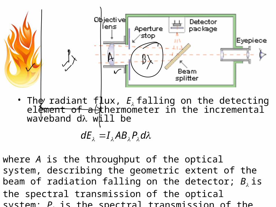
• The radiant flux, E falling on the detecting element of a thermometer in the incremental waveband d will be
dPABIdE
where A is the throughput of the optical system, describing the geometric extent of the beam of radiation falling on the detector; B is the spectral transmission of the optical system: P, is the spectral transmission of the medium between the instrument and the target.
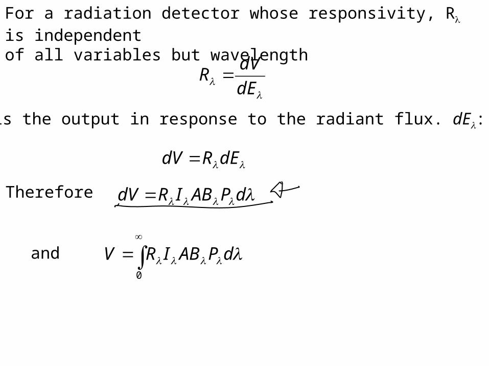
For a radiation detector whose responsivity, R is independentof all variables but wavelength
dE
dVR
where dV is the output in response to the radiant flux. dE:
dERdV
Therefore dPABIRdV
0
dPABIRVand
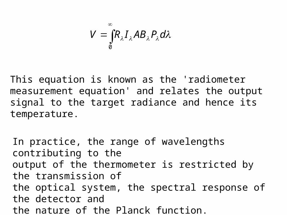
In practice, the range of wavelengths contributing to theoutput of the thermometer is restricted by the transmission ofthe optical system, the spectral response of the detector andthe nature of the Planck function.
This equation is known as the 'radiometer measurement equation' and relates the output signal to the target radiance and hence its temperature.
0
dPABIRV
Design features
The basic measurement system for a radiation thermometer comprises the following elements.
(1) The target of measurement.(2) An optical system which collects and directs the radiation.
Elements of the optical system may also be used to modify the spectral response of the thermometer.
(3) A sensor which produces a signal, usually electrical, related to the incident energy flux.
(4) A reference source which may be physically situated in the instrument itself or located in a calibration laboratory.
(5) A means of signal processing and display.

Anatomy of Radiation Pyrometers

• The design of the instrument must allow a measurement to be made with acceptable accuracy and repeatability given all the circumstances of the target, the instrument itself and the surrounding environment.
• The most important choice which faces the designer, and indeed the user is that of the operating waveband for the instrument.
• There are several factors, some of them conflicting, which need to be considered carefully when choosing the span of wavelengths to be used.
• First of all, consider an instrument sensitive to a narrow waveband d, centered on wavelength .
• Using the approximate form of Planck's equation which is valid for most practical circumstances:
1125
2
,
1
12,
msrWm
e
hcTI
kT
hcb
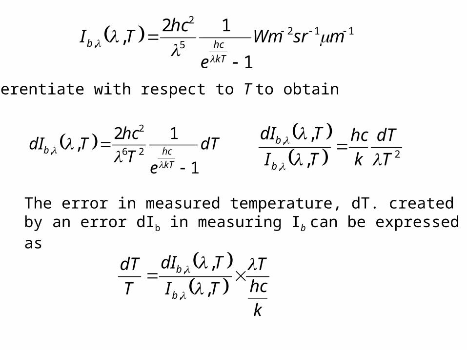
we differentiate with respect to T to obtain
1125
2
,
1
12,
msrWm
e
hcTI
kT
hcb
dT
eT
hcTdI
kT
hcb
1
12,
26
2
,
2
,
,
,
,
T
dT
k
hc
TI
TdI
b
b
The error in measured temperature, dT. created by an error dIb in measuring Ib can be expressed as
khcT
TI
TdI
T
dT
b
b
,
,
,
,
Precision of Radiation Thermometers
• This relationship indicates that the precision with which the output needs to be measured in order to achieve a required accuracy increases with wavelength.
• For this reason it is advantageous to work with the shortest possible wavelength.
• The nature of the Planck's law curve sets a lower practical limit on the wavelength which can be used at a particular temperature.
• The bandwidth of radiation accepted by the instrument must be sufficiently wide to create a signal from the detector that can be measured with acceptable accuracy, in comparison with the system noise.
• Finally, the waveband chosen must be free from absorption effects in the sight path of the thermometer.
• There is no single solution which is best for every application and care must be exercised in choosing the correct waveband.

Classification of Thermometers
• (1) Partial radiation thermometers:
• These use a fraction of the spectrum defined by the spectral response of the detector and the optical system.
• (2) Total radiation thermometers: These use virtually the whole of the spectrum.
• (3) Ratio or two-colour thermometers: These use two distinct wavebands.
• Thermometers of all types may be constructed either as portable, hand-held devices or as units for permanent installation in a fixed position.
Partial Radiation Thermometers
• The advantage of using short wavelengths can be conveniently realised by using an instrument sensitive to all wavelengths shorter than a limiting value which is set by the characteristics of the detector or a filter incorporated into the optical system.
• Thermometers of this type are widely used in many applications for the measurement of temperatures above 500C.
• Photon detectors such as silicon and germanium photodiodes are often used because their spectral response is of an appropriate form, and lies in the part of the spectrum where the rate of energy emission is high.
• This type of thermometer is the one most frequently encountered.
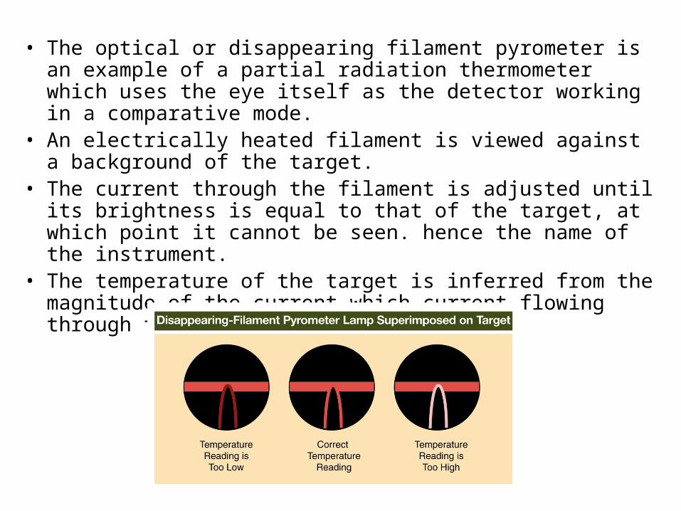
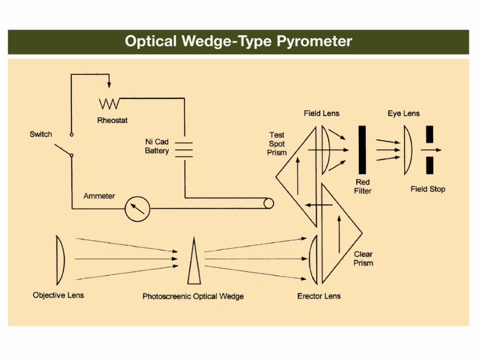
• The optical or disappearing filament pyrometer is an example of a partial radiation thermometer which uses the eye itself as the detector working in a comparative mode.
• An electrically heated filament is viewed against a background of the target.
• The current through the filament is adjusted until its brightness is equal to that of the target, at which point it cannot be seen. hence the name of the instrument.
• The temperature of the target is inferred from the magnitude of the current which current flowing through the filament.
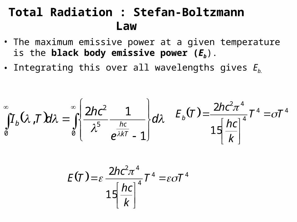
Total Radiation : Stefan-Boltzmann Law
• The maximum emissive power at a given temperature is the black body emissive power (Eb).
• Integrating this over all wavelengths gives Eb.
05
2
0 1
12,
d
e
hcdTI
kT
hcb 44
4
42
15
2TT
khc
hcTEb
444
42
15
2TT
khc
hcTE
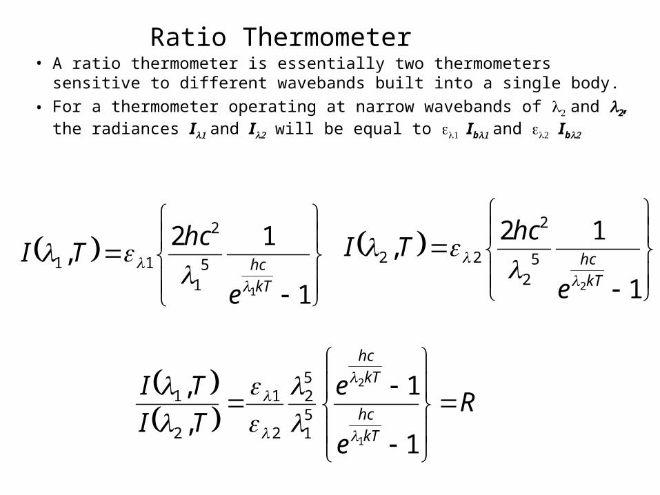
Ratio Thermometer• A ratio thermometer is essentially two thermometers sensitive to
different wavebands built into a single body.
• For a thermometer operating at narrow wavebands of and 2, the radiances I and I will be equal to Ib and Ib
1
12,
1
51
2
11
kT
hc
e
hcTI
1
12,
2
52
2
22
kT
hc
e
hcTI
R
e
e
TI
TI
kT
hc
kT
hc
1
1
,
,
1
2
51
52
2
1
2
1
• The signals from the detectors are processed to produce an output which is a function of R.
• If = i.e., the body is grey, then the output is independent of emissivity.
• Similarly the output will be unaffected by partial obscuration of the target provided that both channels are equally affected.
• At first sight the ratio thermometer appears very attractive.• It does, however, suffer from some limitations. • First, very few bodies are exactly ‘grey’ and the deviation from
‘greyness’ creates a measurement error if it is not known accurately. • Furthermore the inherent accuracy of a ratio thermometer is less
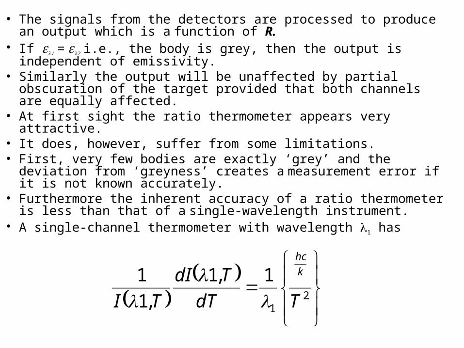
than that of a single-wavelength instrument.• A single-channel thermometer with wavelength has
2
1
1,1
,1
1
TdT
TdI
TI
k
hc
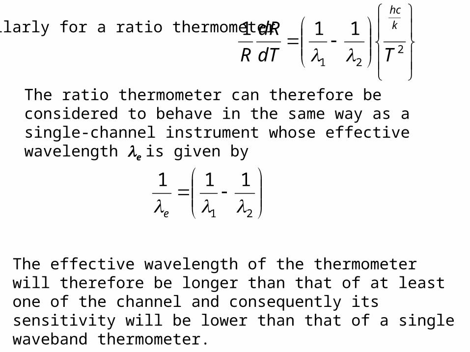
Similarly for a ratio thermometer
221
111
TdT
dR
R
k
hc
The ratio thermometer can therefore be considered to behave in the same way as a single-channel instrument whose effective wavelength e is given by
21
111
e
The effective wavelength of the thermometer will therefore be longer than that of at least one of the channel and consequently its sensitivity will be lower than that of a single waveband thermometer.
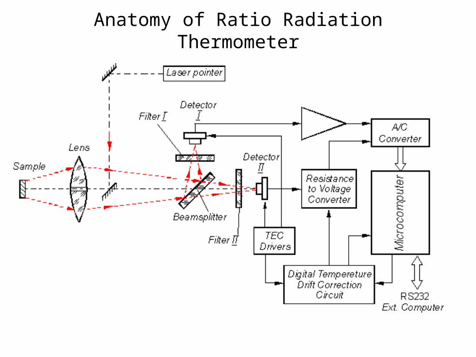
Anatomy of Ratio Radiation Thermometer

Principal components of radiation thermometers
• All radiation thermometers contain the same principal elements, namely
• an optical system.
• a detector and
• signal processing facilities.
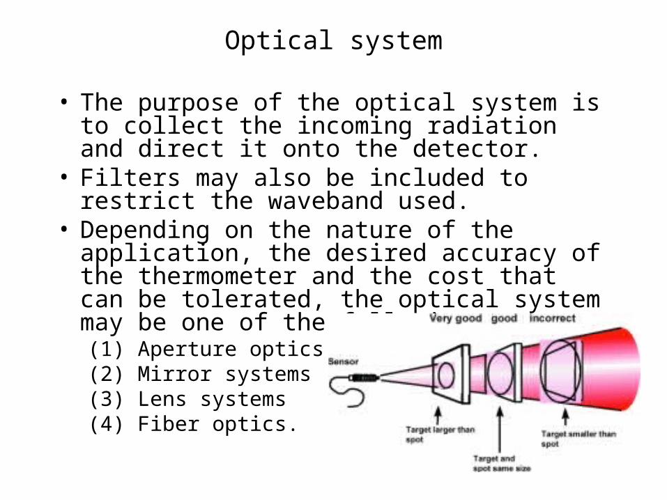
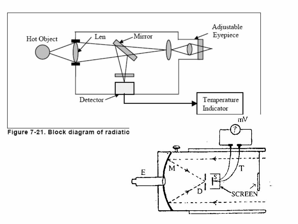
Optical system
• The purpose of the optical system is to collect the incoming radiation and direct it onto the detector.
• Filters may also be included to restrict the waveband used.
• Depending on the nature of the application, the desired accuracy of the thermometer and the cost that can be tolerated, the optical system may be one of the following types:(1) Aperture optics(2) Mirror systems(3) Lens systems(4) Fiber optics.
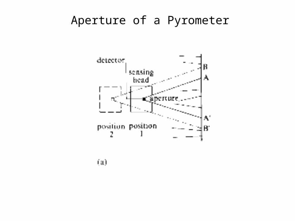
Aperture of a Pyrometer
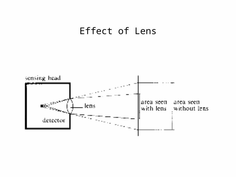
Effect of Lens

Detectors• The detector is the key component in a radiation thermometer,
being the means by which the incident radiation is converted to a measurable parameter.
• parameters by which a detector is selected.• (i) Spectral responsivity describes in a relative sense the manner
in which the output of the detector varies with the wavelength of the incoming radiation.
• It can be expressed in terms either of output per unit of incident energy in a given wavelength interval or of output per photon arriving in the wavelength interval.
• (ii) Detectivity describes the signal-to-noise ratio of the detector in relation to incident radiant power, and defines the resolving power of the detector.
• (iii) Linearity. A linear relationship between the output of a detector and the incident radiation flux is a useful property.
• (iv) Response time describes the manner in which a detector responds to changes in the incident radiation.

Thermal Detectors
• The incident radiation causes an increase in temperature of the detector, thereby creating a change in its temperature-dependent properties.
• The measurement of one of these will provide information about the temperature of the detector and, by inference, the rate of incident energy and the temperature of the source of the radiation.
• Thermal detectors generally have a spectral response which is uniform over a broad band, making them particularly useful for total radiation and wide-band thermometers.
• The most commonly used thermal detectors are thermopiles, bolometers and pyroelectric crystals.
Photon Detectors
• Photon detectors are those in which the incidence of a photon causes a change in the electronic state of the detector.
• The integrated effect of individual photons creates a change of measurable magnitude.
• There are numerous photon effects of which the photoconductive and photovoltaic effects are those most commonly used for the detection and measurement of infrared radiation.
• In either case incident photons excite carriers in the detector material from a non-conducting to a conducting state.
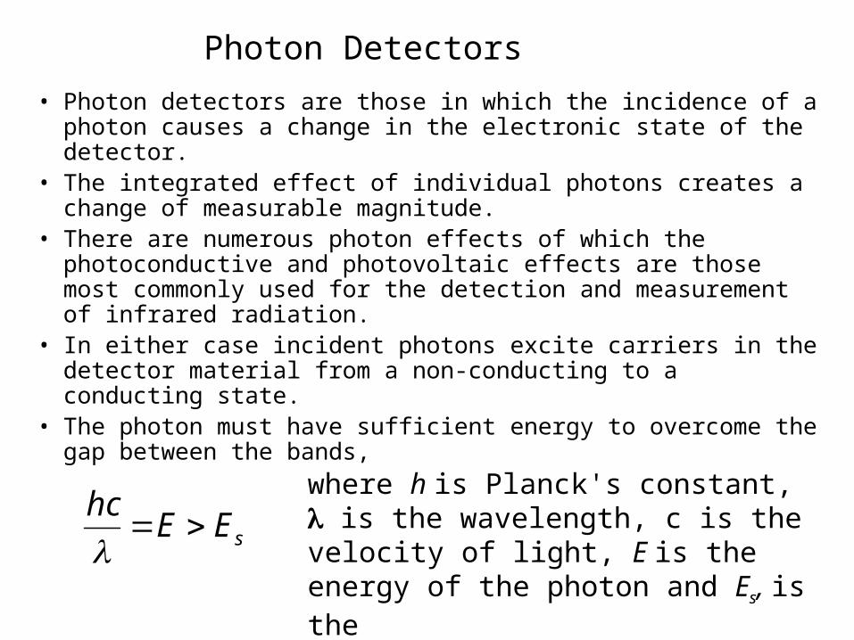
• The photon must have sufficient energy to overcome the gap between the bands,
sEEhc
where h is Planck's constant, is the wavelength, c is the velocity of light, E is the energy of the photon and Es, is theexcitation energy.

Spectral response of a photon detector
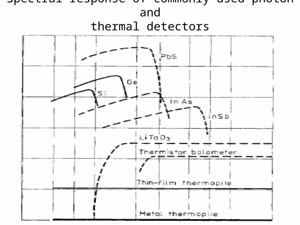
Spectral response of commonly used photon andthermal detectors
Non Black Bodies : Determining Emissivity
• There are various methods for determining the emissivity of an object.
• Emissivity of many frequently used materials in a table.
• Particularly in the case of metals, the values in such tables should only be used for orientation purposes since the condition of the surface can influence emissivity more than the various materials themselves.
Pyrometer with emissivity setting capability
• Heat up a sample of the material to a known temperature that you can determine very accurately using a contact thermometer.
• Then measure the target temperature with the IR thermometer.
• Change the emissivity until the temperature corresponds to that of the contact thermometer.
• Now keep this emissivity for all future measurements of targets on this material.

Reference Target
• At a relatively low temperature (up to 260°C), attach a special plastic sticker with known emissivity to the target.
• Use the infrared measuring device to determine the temperature of the sticker and the corresponding emissivity.
• Then measure the surface temperature of the target without the sticker and re-set the emissivity until the correct temperature value is shown.
• Now, use the emissivity determined by this method for all measurements on targets of this material.
Black Body Reference
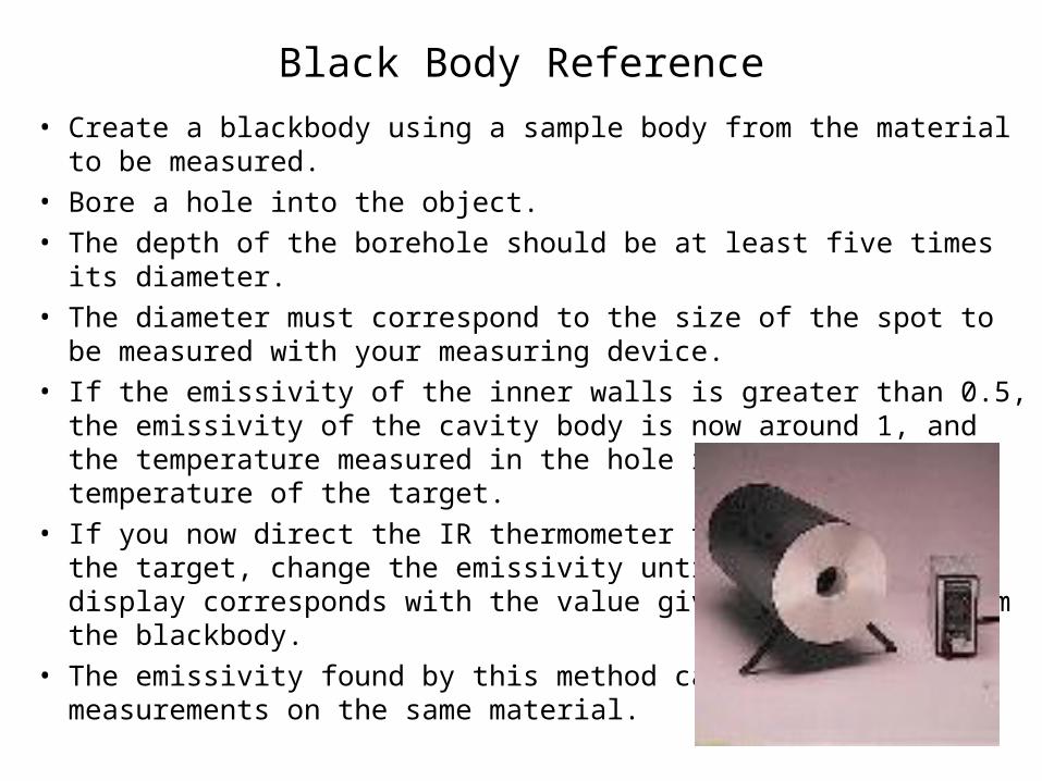
• Create a blackbody using a sample body from the material to be measured.
• Bore a hole into the object.
• The depth of the borehole should be at least five times its diameter.
• The diameter must correspond to the size of the spot to be measured with your measuring device.
• If the emissivity of the inner walls is greater than 0.5, the emissivity of the cavity body is now around 1, and the temperature measured in the hole is the correct temperature of the target.
• If you now direct the IR thermometer to the surface of the target, change the emissivity until the temperature display corresponds with the value given previously from the blackbody.
• The emissivity found by this method can be used for all measurements on the same material.
Reference Black Coating
• If the target can be coated, coat it with a matte black paint.
• "3-M Black" from the Minnesota Mining Company or
• "Senotherm" from Weilburger Lackfabrik, either which have an emissivity of around 0.95).
• Measure the temperature of this blackbody and set the emissivity as described previously.
Merits of Radiation thermometers
• No contact or interference with process• No upper temperature limit as thermometer does not touch
hot body• Accurate and stable over a long period if correctly
maintained• Quick response (1 ms to 1 s, according to type)• Long life• High sensitivity
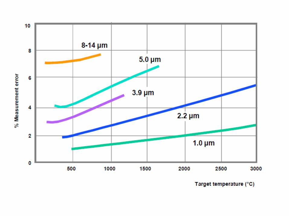

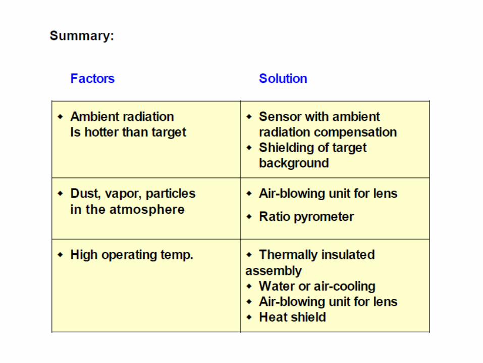
Effect of Ambient Conditions
Typical measuring windows are 1.1--1.7 µm, 2 --2.5 µm,3.5 µm and 8.14 µm.

Point to Field Measurement of Temeprature
Optical Imaging for Temperature Measurement
P M V SubbaraoProfessor
Mechanical Engineering Department
Simultaneous Measurement of Temperature at Infinite Locations …….

Interferometry for Temperature Measurements
• Interferometry is the technique of diagnosing the properties of two or more waves by studying the pattern of interference created by their superposition.
• The instrument used to interfere the waves together is called an interferometer.
• Interferometry is an important investigative technique in the fields of astronomy, fiber optics, engineering metrology, optical metrology, oceanography, seismology, quantum mechanics, nuclear and particle physics, plasma physics, and remote sensing.[
• In an interferometer, light from a single source is split into two beams that travel along different paths.
• The beams are recombined to produce an interference pattern that can be used to detect changes in the optical path length in one of the two arms.
• Here we discuss about the use of the Mach-Zehnder interferometer in measurements of the index of refraction.
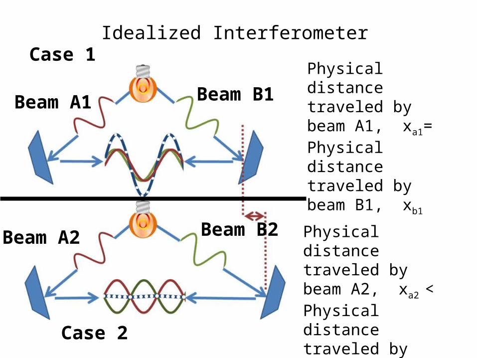
Idealized InterferometerCase 1
Case 2
Beam A1 Beam B1
Beam A2 Beam B2
Physical distance traveled by beam A1, xa1= Physical distance traveled by beam B1, xb1
Physical distance traveled by beam A2, xa2 < Physical distance traveled by beam B2, xb2
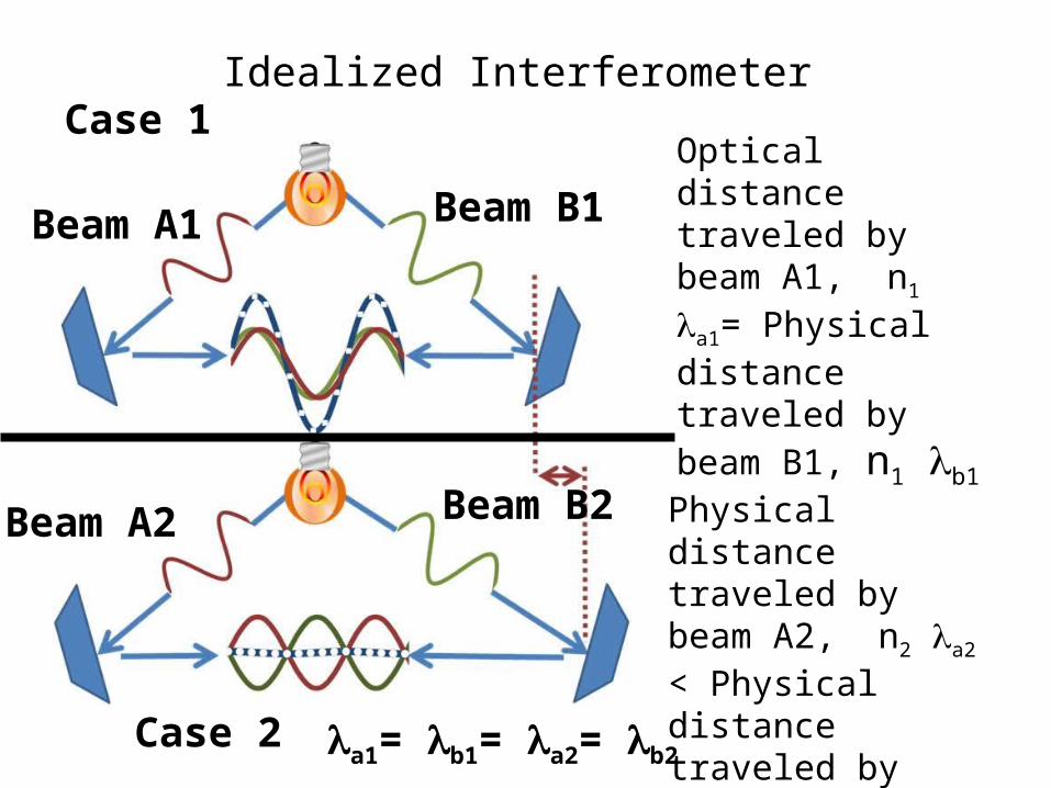
Idealized InterferometerCase 1
Case 2
Beam A1 Beam B1
Beam A2 Beam B2
Optical distance traveled by beam A1, n1 a1= Physical distance traveled by beam B1, n1 b1
Physical distance traveled by beam A2, n2 a2 < Physical distance traveled by beam B2, n2 b2
a1= b1= a2= b2

Schematic diagram of the Mach-Zehnder interferometer
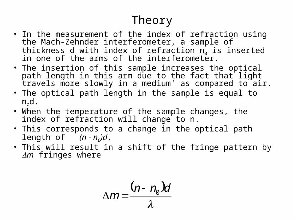
Theory• In the measurement of the index of refraction using the Mach-
Zehnder interferometer, a sample of thickness d with index of refraction n0 is inserted in one of the arms of the interferometer.
• The insertion of this sample increases the optical path length in this arm due to the fact that light travels more slowly in a medium' as compared to air.
• The optical path length in the sample is equal to n0d. • When the temperature of the sample changes, the index of
refraction will change to n. • This corresponds to a change in the optical path length of (n -
n0)d. • This will result in a shift of the fringe pattern by m fringes
where
dnnm 0

Index of Refraction of Water
• The dependence of the index of refraction n of water on wavelength, temperature and density hasrecently been studied by Schiebener et.
• Using a large number of experimental data sets published between 1870 and 1990 they arrived at the following formula
where

is the density, is the wavelength, T the absolute temperature, a0 to a7 are dimensionless coefficients, and
r and uv are the effective infrared and ultraviolet resonances respectively.
The equation holds for the following ranges:
Index of Refraction of Air
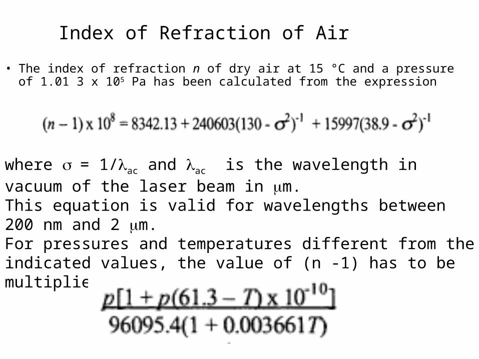
• The index of refraction n of dry air at 15 °C and a pressure of 1.01 3 x 10⁵ Pa has been calculated from the expression
where = 1/ac and ac is the wavelength in vacuum of the laser beam in m. This equation is valid for wavelengths between 200 nm and 2 m. For pressures and temperatures different from the indicated values, the value of (n -1) has to be multiplied by

Experimental Set-up
Test Field
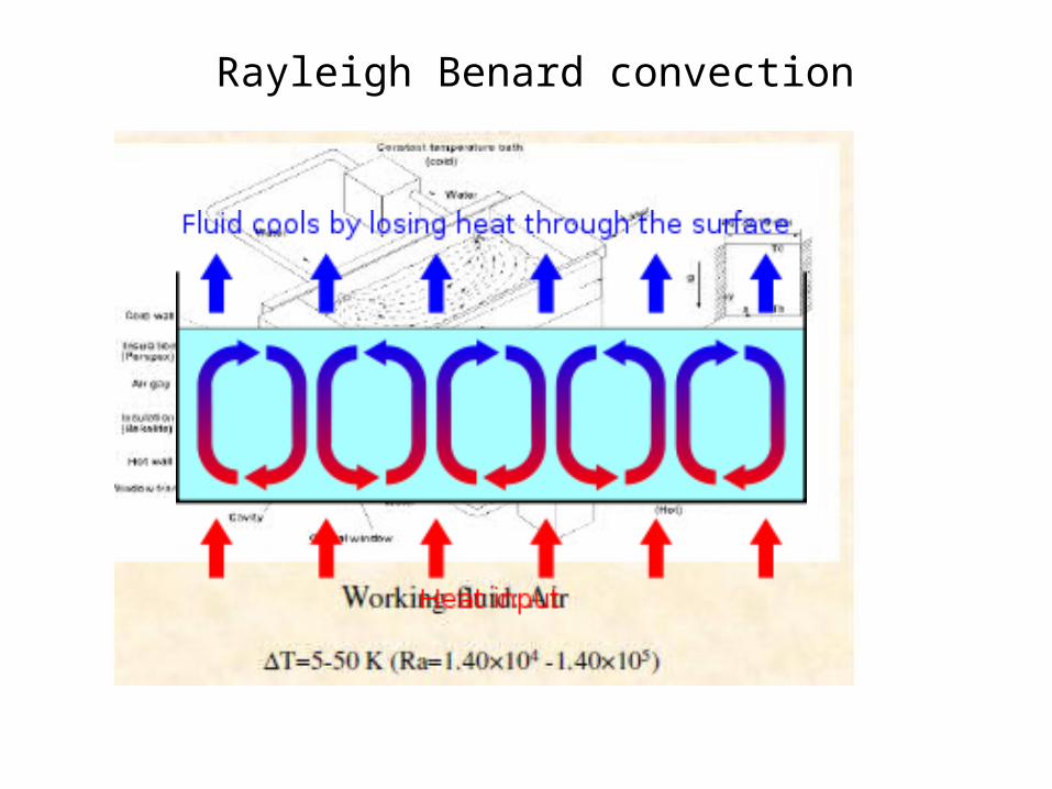
Rayleigh Benard convection
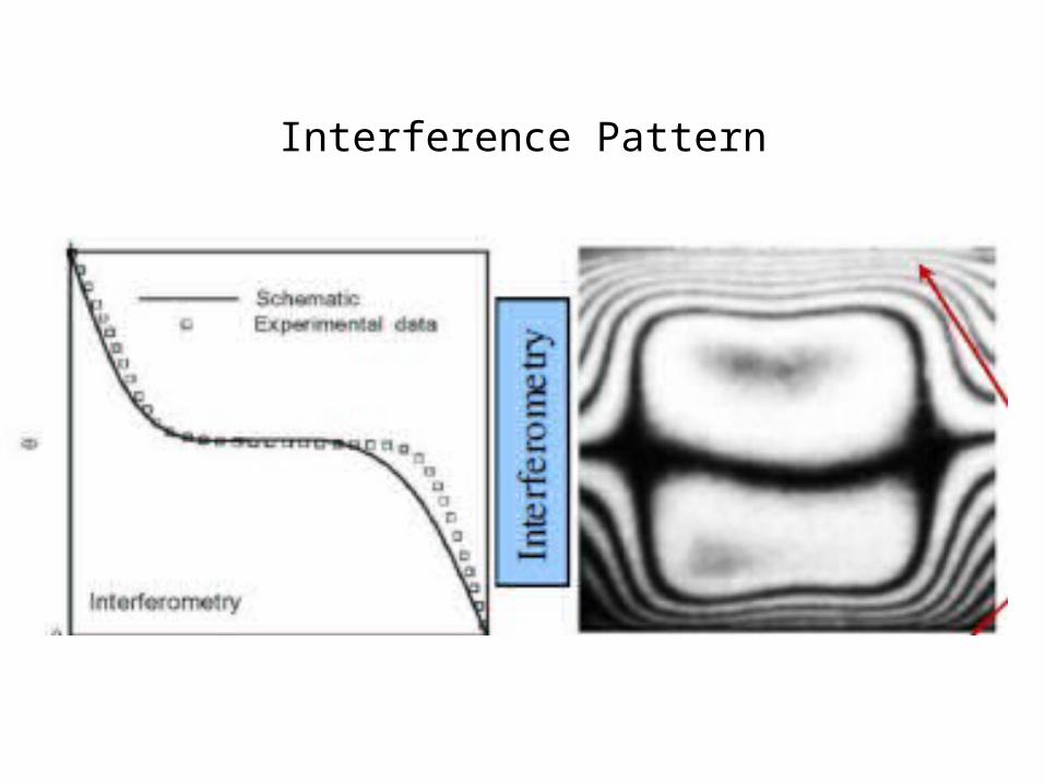
Interference Pattern
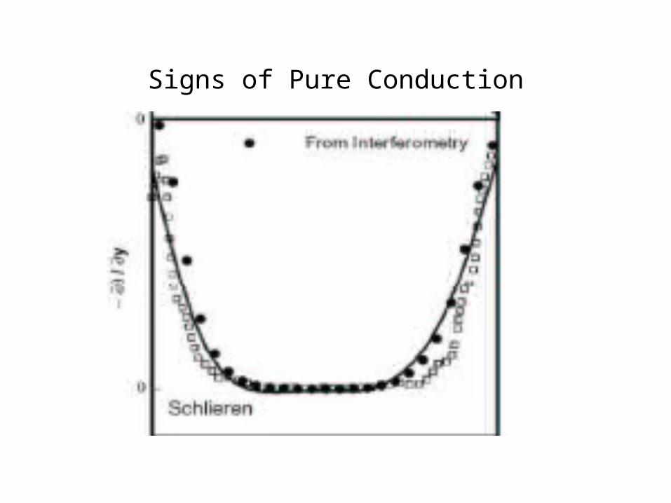
Signs of Pure Conduction

Onset of Convection
Ra = 1.4 X 10⁴ Ra = 5.0 X 10⁴
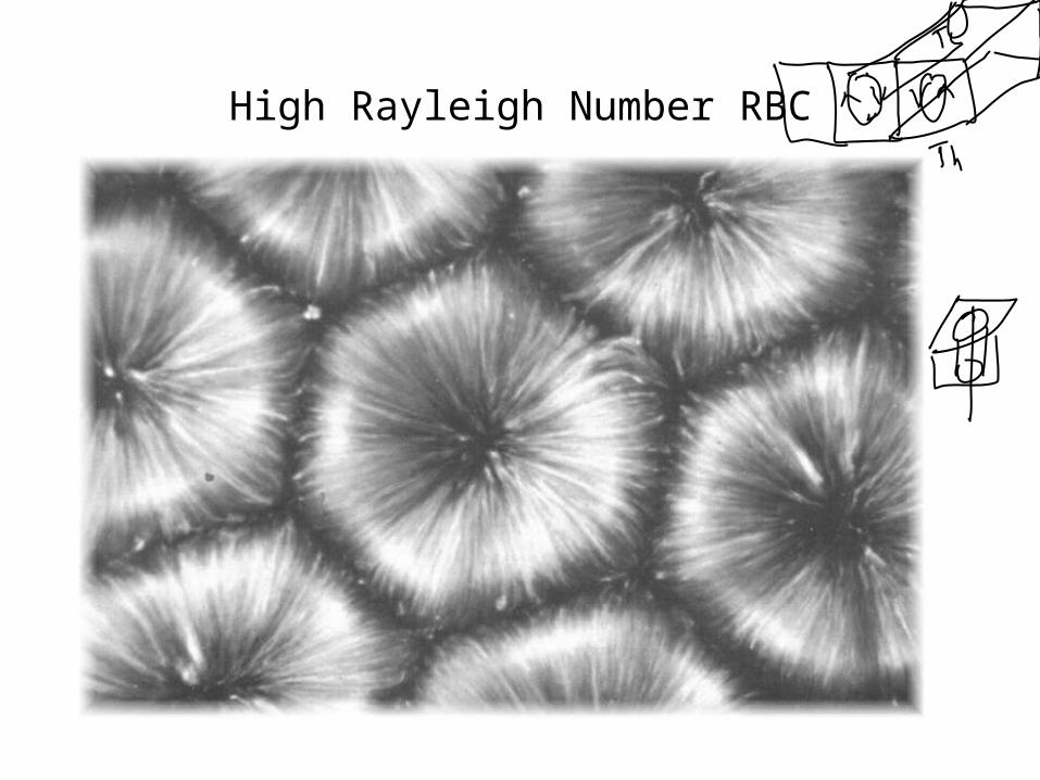
High Rayleigh Number RBC
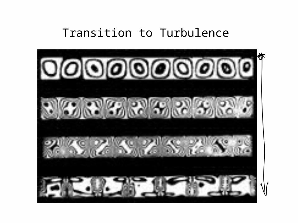
Transition to Turbulence

Natural Convection Fringes


