48
RADID NEWS RADIO -ELECTRONIC DE PARJM ENT APRIL 1944 ELECTRONICS RADAR COMMUNICATIONS TELEVISION RESEARCH MAINTENANCE
RADID NEWS
RADIO -ELECTRONIC
DE PARJM ENT
APRIL 1944
ELECTRONICS
RADAR COMMUNICATIONS
TELEVISION
RESEARCH
MAINTENANCE
RADIO NEWS
RADIO ElECTRONIC
DEPARTMEN
ELECTRONICS COMMUNICATIONS TELEVISION RESEARCH MAINTENANCE
APR,IL, 1944
ULTRA HIGH FREQUENCY EQUIPMENT R. E. Soria 3
PHOSPHORS FOR ELECTRON TUBES H. W. Leverenz 9
ELECTRONIC CONTROL MAINTENANCE R. H. Schaaf 13
ELECTRON OPTICS D. Fidelman 16
IMPEDANCE NOMOGRAM B. S. Branch 20
R -F FEEDERS R. A. Whiteman 22
CATHODE-RAY TELEVISION TUBES Harry D. Hooton 26
NEW PRODUCTS 30
INDUSTRIAL REVIEW 32
NEWSBRIEFS 34
CALENDAR 36
TECHNICAL BOOKS 42
PERSONALS 44
RADIO -ELECTRONIC ENGINEERING is published each month as a special edition in a limited number of copies of RADIO NEWS, by the Ziff -Davis Publishing Company, 540 N.
Michigan Avenue, Chicago, Ill.
VOLUME 2 NUMBER 4 Copyright, 1944, Ziff -Davis Publishing Company
COVER PHOTO-BY WESTINGHOUSE Making adjustments on the large air-cooled ignitrons used in industrial applications. These tubes are used as rectifiers supplying power to general industrial loads and to small isolated loads in cities using a -c networks.
2 ENGINEERING DEPARTMENT

ULTRA HIGH FREQUENCY
EQUIPMENT
Copper horn and reflector for UHF transmission.
By R. E. SORIA Illinois Institute of Technology
The characteristics of cavity resonators, horns and UHF generators applied to the transmitting and receiving of 3000 megacycle waves.
WiTH the comparatively recent application of frequencies well above 30 mc/s it has be-
come necessary for the engineer to be- come familiar with the factors in- volved at ultra -high -frequencies. The engineer having a knowledge of audio - frequency circuits is not too much con- cerned with skin effect, lead induct- ance, transit time, and the other ultra- high -frequency phenomena. However, now it is essential for the engineer to become acquainted with these effects by means of clearly designed and in- structive equipment.
To perform any kind of work in the ultra -high -frequency range a stable generator of sufficient output is es- sential. Starting with oscillators the following will present a brief outline of the important ultra -high -frequency equipment used in this work. Negative Grid Oscillators
Ordinary vacuum -tube oscillators
when modified for ultra -high -frequen- cies are commonly called negative grid oscillators. The tubes used are al- most always triodes. The high grid to plate capacitance is ordinarily unde- sirable in amplifiers, but may be made to serve as part of the resonant cir- cuit of an oscillator. The additional grids in the pentode although decreas- ing the grid to plate capacitance raise to total shunt capacitance and thus reduce the maximum possible fre- quency of oscillation.
The frequency range of ordinary triodes used for ultra -high -frequency oscillators is limited primarily by three factors. With increase in frequency the lead inductance and interelectrode capacitance become appreciable, and the transit time of the electrons from cathode to plate becomes of the same order of magnitude as the period of oscillation. The high lead inductance and interelectrode capacitance pro-
duce a high input conductance and thus a large power loss. The electron transit time causes the input shunt resistance to drop to a low value, de- creasing the effective Q of the resonant circuit and therefore also absorbing power. In addition the transit time affects the phase angle of the trans - conductance, the plate current no longer being 180° out of phase, the grid voltage at high frequencies. If it is desired to . fix some frequency limit of the negative grid triode oscil- lator we can say that below about 20 centimeter wave length the output power will have dropped to less than 1/10 of a watt which is insignificant to be of any practical use. Experi- ments with the physical construction of negative grid triode oscillators have conclusively shown that a reduction of all physical dimensions and direct anchorage of the electrode leads in the glass envelope reduces both the
ENGINEERING DEPARTMENT 3.
interelectrode capacitances and the lead inductances, and also reduces the effect of the transit time. Reducing the dimensions of the tube, on the other hand, reduces the power capacity because of the smaller cathode -emit- ting surface and the smaller heat -dis- sipating capacity of the plate. It be- comes necessary, therefore, to use as efficient an external resonant circuit as possible. Ordinary lumped induct- ance and capacitance tuned circuits lose their identity at ultra -high -fre- quencies, their Q drops to an insignifi- cant value. A tank circuit with a much higher Q may be obtained by using a quarter wave length long transmission line short-circuited at one end. Above 300 mc/s coaxial lines should be used to avoid excessive radi- ation losses, a ratio of 3.6 between the radii of the outer and the inner conductor giving maximum Q.
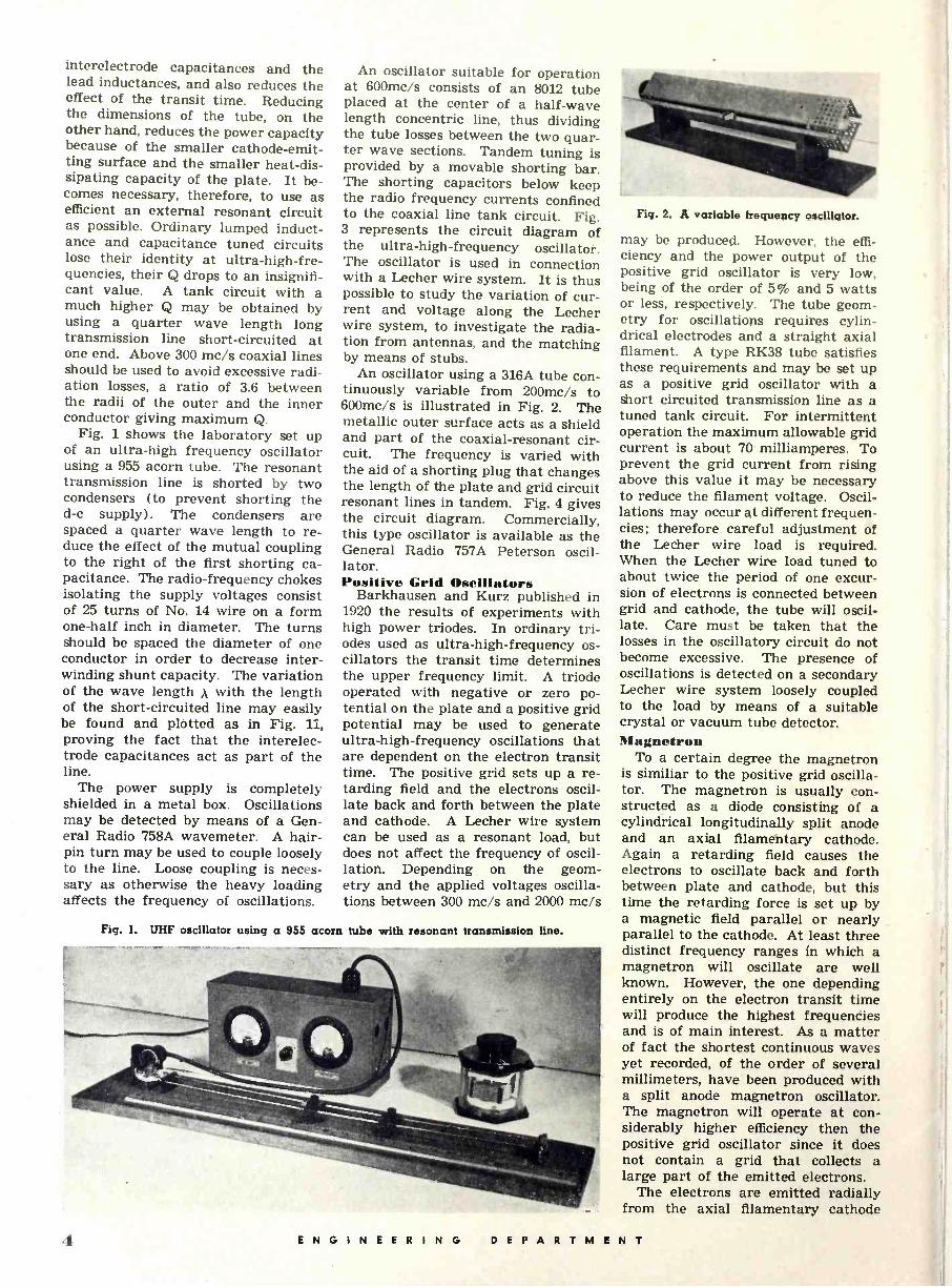
Fig. 1 shows the laboratory set up of an ultra -high frequency oscillator using a 955 acorn tube. The resonant transmission line is shorted by two condensers (to prevent shorting the d -c supply). The condensers are spaced a quarter wave length to re- duce the effect of the mutual coupling to the right of the first shorting ca- pacitance. The radio -frequency chokes isolating the supply voltages consist of 25 turns of No. 14 wire on a form one-half inch in diameter. The turns should be spaced the diameter of one conductor in order to decrease inter - winding shunt capacity. The variation of the wave length A with the length of the short-circuited line may easily be found and plotted as in Fig. 11, proving the fact that the interelec- trode capacitances act as part of the line.
The power supply is completely shielded in a metal box. Oscillations may be detected by means of a Gen- eral Radio 758A wavemeter. A hair- pin turn may be used to couple loosely to the line. Loose coupling is neces- sary as otherwise the heavy loading affects the frequency of oscillations.
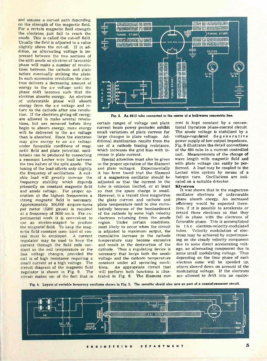
An oscillator suitable for operation at 600mc/s consists of an 8012 tube placed at the center of a half -wave length concentric line, thus dividing the tube losses between the two quar- ter wave sections. Tandem tuning is provided by a movable shorting bar. The shorting capacitors below keep the radio frequency currents confined to the coaxial line tank circuit. Fig. 3 represents the circuit diagram of the ultra -high -frequency oscillator. The oscillator is used in connection with a Lecher wire system. It is thus possible to study the variation of cur- rent and voltage along the Lecher wire system, to investigate the radia- tion from antennas, and the matching by means of stubs.
An oscillator using a 316A tube con- tinuously variable from 200mc/s to 600mc/s is illustrated in Fig. 2. The metallic outer surface acts as a shield and part of the coaxial -resonant cir- cuit. The frequency is varied with the aid of a shorting plug that changes the length of the plate and grid circuit resonant lines in tandem. Fig. 4 gives the circuit diagram. Commercially, this type oscillator is available as the General Radio 757A Peterson oscil- lator. Positive Grid Oscillators
Barkhausen and Kurz published in 1920 the results of experiments with high power triodes. In ordinary tri- odes used as ultra -high -frequency os- cillators the transit time determines the upper frequency limit. A triode operated with negative or zero po- tential on the plate and a positive grid potential may be used to generate ultra -high -frequency oscillations that are dependent on the electron transit time. The positive grid sets up a re- tarding field and the electrons oscil- late back and forth between the plate and cathode. A Lecher wire system can be used as a resonant load, but does not affect the frequency of oscil- lation. Depending on the geom- etry and the applied voltages oscilla- tions between 300 me/s and 2000 me/s
Fig. 1. UHF oscillator using a 955 acorn tube with resonant transmission line.
Fig. 2. A variable frequency oscillator.
may be produced. However, the effi- ciency and the power output of the positive grid oscillator is very low, being of the order of 5% and 5 watts or less, respectively. The tube geom- etry for oscillations requires cylin- drical electrodes and a straight axial filament. A type RK38 tube satisfies these requirements and may be set up as a positive grid oscillator with a short circuited transmission line as a tuned tank circuit. For intermittent operation the maximum allowable grid current is about 70 milliamperes. To prevent the grid current from rising above this value it may be necessary to reduce the filament voltage. Oscil- lations may occur at different frequen- cies; therefore careful adjustment of the Lecher wire load is required. When the Lecher wire load tuned to about twice the period of one excur- sion of electrons is connected between grid and cathode, the tube will oscil- late. Care must be taken that the losses in the oscillatory circuit do not become excessive. The presence of oscillations is detected on a secondary Lecher wire system loosely coupled to the load by means of a suitable crystal or vacuum tube detector. Magnetron
To a certain degree the magnetron is similiar to the positive grid oscilla- tor. The magnetron is usually con- structed as a diode consisting of a cylindrical longitudinally split anode and an axial filamentary cathode. Again a retarding field causes the electrons to oscillate back and forth between plate and cathode, but this time the retarding force is set up by a magnetic field parallel or nearly parallel to the cathode. At least three distinct frequency ranges in which a magnetron will oscillate are well known. However, the one depending entirely on the electron transit time will produce the highest frequencies and is of main interest. As a matter of fact the shortest continuous waves yet recorded, of the order of several millimeters, have been produced with a split anode magnetron oscillator. The magnetron will operate at con- siderably higher efficiency then the positive grid oscillator since it does not contain a grid that collects a large part of the emitted electrons.
The electrons are emitted radially from the axial filamentary cathode
4 ENGINEERING DEPARTMENT
and assume a curved path depending on the strength of the magnetic field. For a certain magnetic field strength the electrons just fail to reach the anode. This is called the cut-off field. Usually the field is adjusted to a value slightly above the cut-off. If in ad- dition, an alternating voltage is im- pressed between the two sections of the split anode an electron of favorable phase will make a number of revolu- tions between the cathode and plate before eventually striking the plate. In each successive revolution the elec- tron delivers a decreasing amount of energy to the a -c voltage until the phase shift becomes such that the electron absorbs energy. An electron of unfavorable phase will absorb energy from the a -c voltage and re- turn to the cathode after one revolu- tion. If the electrons giving off energy are allowed to make several revolu- tions, but are removed before they begin to absorb energy, more energy will be delivered to the a -c voltage than is absorbed. Since the electrons may give energy to an a -c voltage under favorable conditions of mag- netic field and plate potential, oscil- lations can be produced by connecting a resonant Lecher wire load between the two halves of the split anode. The tuning of. the load affects only slightly the frequency of oscillations. A suit- able load will greatly increase the frequency stability which depends primarily on constant magnetic field and anode voltage. For proper op- eration at the highest frequencies a strong magnetic field is necessary. Approximately 100,000 ampere -turns per meter (1200 gauss) is required at a frequency of 3000 me/s. For ex- perimental work it is convenient to use an electro -magnet to produce the magnetié' field. To keep the mag- netic field constant some kind of con- trol must be employed. A current regulator may be used to keep the current through the field coils con- stant as the coil temperature or the line voltage changes, provided the coil is of high resistance requiring a small current at a high voltage. The circuit diagram of the magnetic field regulator is shown in Fig. 9. The circuit makes use of the fact that in
.. .... .. s.es!::.
Fig. 3. An 8012 tube connected to the center of a half -wave concentric line.
certain ranges of voltage and plate current beam power pentodes exhibit small variations of plate current for large changes in plate voltage. Ad- ditional stabilization results from the use of a cathode biasing resistance, which increases the grid bias with in- crease in plate current.
Special attention must also be given to the proper operation of the filament and plate voltages. Experimentally it has been found that the filament of a magnetron oscillator should be adjusted so that the current in the tube is emission limited, or at least so that the space charge is small. However, in a transit time magnetron the plate current and cathode and plate temperature tend to rise cumu- latively because of the bombardment of the cathode by some high velocity electrons returning from the anode region. Under certain conditions, most likely to occur when the circuit is adjusted to maximum output, the cumulative increase in the cathode temperature may become excessive and result in the destruction of the cathode. Thus a regulating device is necessary that keeps both the anode voltage and the cathode temperature constant under all operating condi- tions. An appropriate circuit that will perform both functions is illus- trated in Fig. 8. The filament cur-
rent is kept constant by a conven- tional thyratron phase -control circuit. The anode voltage is stabilized by a voltage -regulated d e g e n e r a t i v e power supply of low output impedance. Fig. 8 illustrates the detail connections of the 884 tube in a current controlled unit. Measurements of the change of wave length with magnetic field and with plate voltage can easily be per- formed. A load may be coupled to the Lecher wire system by means of a hairpin turn. Oscillations are indi- cated on a suitable detector. Hlystron
It was shown that in the magnetron oscillator electrons of unfavorable phase absorb energy. An increased efficiency would be expected there- fore, if it is possible to accelerate or retard these electrons so that they fall in phase with the electrons of favorable phase. This is accomplished in t h e electron -velocity -modulated tubes. Velocity modulation of elec- trons may be achieved by superimpos- ing on the steady velocity component due to some direct accelerating volt- age, an alternating component due to some small modulating voltage. Thus depending on the time phase of each electron some will be speeded up, others slowed down on account of the modulating voltage. If the electrons are allowed to drift into an equipo -
Fig. 4. Layout of variable frequency oscillator shown in Fig. 2. The metallic shield also acts as part of a coaxial -resonant circuit.
ENGINEERING DEPARTMENT 5
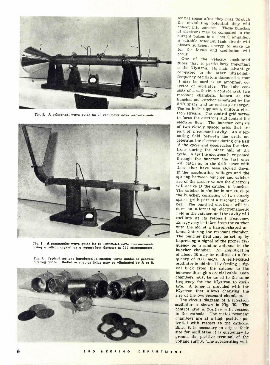
Fig. 5. A cylindrical wave guide for 10 centimeter -wave measurements.
Fig. 6. A rectangular wave guide for 10 centimeter -wave measurements using a silicon crystal as a square -law detector to 100 microamperes.
Fig. 7. Typical sections introduced in circular wave guides to produce filtering action. Radial or circular fields may be eliminated by A or B.
tential space after they pass through the modulating potential they will collect into bunches. These bunches of electrons may be compared to the current pulses in a class C amplifier. A suitable resonant tank circuit will absorb sufficient energy to make up for the losses and oscillation will occur.
One of the velocity modulated tubes that is particularly important is the Klystron. Its main advantage compared to the other ultra -high - frequency oscillators discussed is that it may be used as an amplifier, de- tector or oscillator. The tube con- sists of a cathode, a control grid, two resonant chambers, known as the buncher and catcher separated by the drift space, and an end cap or target. The cathode supplies a uniform elec- tron stream. The control grid serves to focus the electrons and control the electron flow. The buncher consists of two closely spaced grids that are part of a resonant cavity. An alter- nating field between the grids ac- celerates the electrons during one half of the cycle and decelerates the elec- trons during the other half of the cycle. After the electrons have passed through the buncher the fast ones will catch up in the drift space with those that have been slowed down. If the accelerating voltages and the spacing between buncher and catcher are of the proper values the electrons will arrive at the catcher in bunches. The catcher is similar in structure to the buncher, consisting of two closely spaced grids part of a resonant cham- ber. The bunched electrons will in- duce an alternating electromagnetic field in the catcher, and the cavity will oscillate at its resonant frequency. Energy may be taken from the catcher with the aid of a hairpin -shaped an- tenna entering the resonant chamber. The buncher field may be set up by impressing a signal of the proper fre- quency on a similar antenna in the buncher chamber. An amplification of about 10 may be realized at a fre- quency of 3000 me/s. A self-excited oscillator is obtained by feeding a sig- nal back from the catcher to the buncher through a coaxial cable. Both chambers must be tuned to the same frequency for the Klystron to oscil- late. A tuner is provided with the Klystron that allows changing the size of the two resonant chambers.
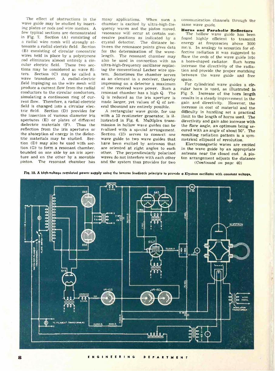
The circuit diagram of a Klystron oscillator is shown in Fig. 10. The control grid is positive with respect to the cathode. The metal resonant chambers are at a high positive po- tential with respect to the cathode. Since it is necessary to adjust their size for oscillation it is customary to ground the positive terminal of the voltage supply. The accelerating volt -
G E N G I N E E R I N G DEPARTMENT

age is rather critical for oscillations and also for good frequency stability and therefore it is necessary to regu- late the plate supply voltage. The regulated power supply for the Klys- tron is illustrated in Fig. 10. Oscil- lations may be observed by a crystal detector connected to a hairpin an- tenna in either the catcher or buncher chamber. A coaxial output terminal fed from an antenna loop in the catcher chamber is usually provided. Wave Guides
At ultra -high -frequencies the losses in a conventional coaxial transmission line become rather excessive and the efficiency of coaxial lines may be greatly increased by omitting the cen- ter conductor. A transmission line of this type is called a hollow wave guide. Radiation losses are practically nonexistent in a wave guide since the energy is completely confined to the interior of the guide. Conduction losses can be appreciably reduced by silver coating the interior surface of the wave guide.
A cylindrical wave guide is set up in Fig. 5. For use with a 10 centi- meter wave length generator the cyl- indrical wave guide should have an inside diameter of approximately 3 inches, permitting only the lowest or- der transverse electric wave to be propagated. The wave guide is built up of several solid brass sections joined by flanges and fastened together by a pin and slot arrangement. Each sec- tion has a particular function and will be considered separately. The trans- fer section (A) is used to feed a sig- nal to the wave guide by means of an antenna rod, or to receive energy that
Fig. 9. A current regulated supply for magnetron electromagnet.
is being propagated through the guide. The antenna rod is part of the coaxial line (B) coming from the gen- erator or leading to the receiver re- spectively. The antenna rod is termi- nated in a coaxial tuner (C), consist- ing of an adjustable short-circuited stub. Thus it is possible to match the antenna to the coaxial line. The transfer section (A) is terminated by a movable piston which can be dis- placed through a rack-and-pinion ar- rangement. The movable brass pis- ton is provided with a large number of spring brass fingers to obtain good contact with the walls of the section which makes the termination more definite. The adjustable piston as- sures that the radiation from the an- tenna in the back direction will be re- flected in the proper phase. Thus the piston allows matching the antenna to the guide. The traveling detector section (D) is used to explore the wave patterns in the guide. The section (D) is mounted on roller bearings, al-
lowing a complete revolution without changing the position of the attached sections. Approximately 24 inches of this section are slotted and a detector unit (E) is allowed to move along the length of the slot to explore the field. The detector unit (E) may consist of a straight pickup rod or a pickup loop connected to a crystal detector and microammeter. Either iron pyrite or silicon crystals are suitable for detec- tors. The d -c detector current fol- lows approximately the square law if the d -c current is held below 100 microamperes. When no deflection is observed as the detector unit (E) is moved along the slotted section, it is safe to assume that no waves are re- flected. No reflections will occur if the wave guide is terminated by a proper impedance. A flared section of guide, referred to as an electromag- netic horn (F), serves as a termination which effectively matches the charac- teristic impedance of the guide to that of free space.
Fig. 8. A filament voltage regulated supply for magnetron oscillator using inverse feedback ettect.
4 MFD. 5W4 1000 V.
6.3 V. 6F6
6SJ7
6.3 V. 6N7 884
R9 RIO
L PILOT
8 4.91
100 MA. FUSE
6N7 OR 6AC7
8-
R2
R4
MAGNETRON FILAMENT
TRANSFORMER
ENGINEERING DEPARTMENT 7
The effect of obstructions in the wave guide may be studied by insert- ing plates or rods and wire meshes. A few typical sections are demonstrated in Fig. 7. Section (A) consisting of a radial wire mesh will strongly at- tenuate a radial electric field. Section (B) consisting of circular concentric wires held in place by a polystyrene rod eliminates almost entirely a cir- cular electric field. These two sec- tions may be considered as wave fil- ters. Section (C) may be called a wave transducer. A radial -electric field impinging on the wire mesh will produce a current flow from the radial conductors to the circular conductors, simulating a continuous ring of cur- rent flow. Therefore, a radial -electric field is changed into a circular elec- tric field. Section (D) provides for the insertion of various diameter iris apertures (E) or plates of different dielectric materials (F). Thus the reflection from the iris apertures or the absorption of energy in the dielec- tric materials may be studied. Sec- tion (D) may also be used with sec- tion (G) to form a resonant chamber, bounded on one side by an iris aper- ture and on the other by a movable piston. The resonant chamber has
many applications. When sucn a chamber is excited by ultra -high -fre- quency waves and the piston moved, resonance will occur at certain suc- cessive positions as indicated by a crystal detector. The distance be- tween the resonance points gives data for the determination of the wave- length. The resonant chamber may also be used in connection with an ultra -high -frequency oscillator replac- ing the conventional Lecher wire sys- tem. Sometimes the chamber serves as an element in a receiver, thereby impressing on a detector a maximum of the received wave power. Such a resonant chamber has a high Q. The Q is reduced as the iris aperture is made larger, yet values of Q of sev- eral thousand are entirely possible.
A rectangular wave guide, for use with a 10 centimeter generator, is il- lustrated in Fig. 6. Multiplex trans- mission in hollow wave guides can be realized with a special arrangement. Section (H) serves to connect one wave guide to two wave guides that have been excited by antennas that are oriented at right angles to each other. The perpendicularly polarized waves do not interfere with each other and the system thus provides for two
communication channels through the same wave guide. Horns and Parabolic Reflectors
The hollow wave guide has been found highly efficient to transmit energy at frequencies above 1000 me/s. In analogy to acoustics for ef- fective radiation it was suggested to flare the ends of the wave guide into a horn -shaped radiator. Such horns increase the directivity of the radia- tion and provide the proper matching between the wave guide and free space.
For cylindrical wave guides a cir- cular horn is used, as illustrated in Fig. 5. Increase of the horn length results in a steady improvement in the gain and directivity. However, the increase in cost of material and the difficulty in handling set a practical limit to the length of horns used. The directivity and gain also increase with the flare angle, an optimum being se- cured with an angle of about 50°. The resulting radiation pattern is a sym- metrical ellipsoid of revolution.
Electromagnetic waves are excited in the wave guide by an appropriate antenna near the closed end. A pis- ton arrangement adjusts the distance
(Continued on page 40)
Fig. 10. A high -voltage regulated power supply using the inverse feedback principle to provide a Klystron oscillator with constant voltage.
>Io
>Io
fo sat fo 10
g -
5Y3
30 HYS.
X TO FILAMENT. TRANSFORMERS
X
!- 3-8 NYS.
I MEG
X
5 V.O( 2 MFD o 0
S AOI 2M V.
X
6A?
6SJ7
50,000
VR -105 VR-150
I0K
100000 20000
0-50
t ei 0-2000
16 MFD
st
.."KLYSTRON
AUDIO
SIGNAL
MOOUI.ATKR TRANSFORMER
º ENGINEERING DEPARTMEN i

Phosphors for Electron Tubes By H. W. LE I ERENZ Research Engineer, RCA Laboratories
1 resumé of the theory of fluorescence and its appli- cation to phosphor chemicals in radio -electron tubes.
THE correlation of optical energy and radio -wave energy has been attempted by scientists with the
aid of the electromagnetic theory of light. This theory alone; however, is inadequate to explain the conversion of kinetic energy of 'a high velocity electron to optical energy by impact upon a phosphor chemical. This action seems to be best explained by apply- ing the quantum theory, an applica- tion of which was first noticed by Ein- stein when analyzing photo -chemical changes.
Practical applications of this theory are found in such commercial items as television Kinescopes, fluorescent lamps, oscilloscopes and indicating tubes such as the Magic Eye. In these tubes the final step of their operation comprises the conversion of electron energy into light or optical energy.
In accordance with the quantum theory, the quantity of optical energy depends upon the frequency as shown by:
E = by (1)
where: X = wavelength in cm. V = frequency in cycles per second c = velocity of light = 3. 1010 cm. per
second h = Planck's constant = 6.55 10-27 erg
sec. and the relation between the wave- length, frequency and velocity is given by the equation:
X v=c (2) To obtain a comparison of the
amounts of energy in radio -wave and light -wave quanta, consider the energy of a quantum of radiation from sta- tion WEAF, whose frequency is 660 kc.
E WEAF = 6.55 10-27.6.6 105 = 4 10-21erg.
The lower part of the optical spec- trum chart shows that orange light has a wavelength of 6100 Angstroms where 1 Angstrom is 10-8 cm. Hence, the energy of a quantum of orange light is
E ORANGE = h v
E ORANGE = h v = 3.2 10 -12 erg
By comparing the above two cal- culations, it is apparent that the quanta of orange light are 80.100
Fig. 1. High temperature treating of phosphors,
times as great as the quanta radiated from WEAF.
This simple calculation gives a quantitative comparison between the energies in two very different portions of the electromagnetic spectrum. In accordance with the Law of Conserva- tion of Energy, the kinetic energy of a moving electron upon impact with a phosphor chemical is converted into heat and light energy.' If, for this particular computation, it is assumed that the efficiency of conversion to light energy is 100 percent, then it is evident that a 2 volt electron would produce light of an orange color which would be visible to the human eye. The kinetic energy of such an electron is :
E = m v2/2 (3) E = e V ergs
where: v = electron velocity in cm. per second m = electron mass in grams e = electron charge of 4.77 10-10 e.s.u. V = accelerating potential in e.s.u. of
potential
Since 300 practical volts are equiva- lent to 1 e.s.u. of potential, the nu- merical value of the kinetic energy for a 2 volt electron is:
E 4.77 .310-10.2 10-12 erg
By comparing the above calcula- tions, it is seen that a quantum of orange light has the same energy as a two volt electron.
Contrary to the general conception of the form of electrons as particles and light as waves, modern wave me- chanics assigns a simultaneous undu- latory and corpuscular character to both electrons and light. For prac- tical purposes, electron energies and light quanta are related by:
Amin = 1.234V 104 Angstroms . . (4)
where A,m in is the wavelength, in Ang- stroms, which would be produced by 100 percent conversion of the energy of an electron, accelerated by V volts, into one quantum of electromagnetic radiation. Since most phosphor chem- icals have efficiencies of conversion well below 100 percent, the actual wavelengths produced will be consid- erably longer than the Amin given by equation (4).
There is a constant number of elec- trons for use in matter, but the num- ber of light quanta may be increased or decreased. This situation may be represented by the notation of a re- versible action as: Fast electron ± Slow electron + Light quantum (5)
When invisible radiations such as ultraviolet, X-rays or cathode rays, having quantum energies greater than about 10-12 erg, impinge upon matter, there is a great probability that the irradiated material may emit elec- trons or light or both as tabulated below:
a. Shortwave light + Matter -* Free electrons
b. Shortwave light -F Matter -) Long - wave Light
c. Fast Electrons -F Matter Slow electrons + Free electrons + Light
Effect - (b) is used in fluorescent lamps wherein invisible ultraviolet ra- diation from an electrical discharge through tenous mercury vapor is effi- ciently transformed by phosphors into visible light.
Effects (a) and (c) are ingeniously
ENGINEERING DEP A R TMENT 9

Fig. 2. A research physicist tests completed phosphors with special electronic equipment.
applied to ultra -short-wave radio to produce electronic television as sketched in Fig. 5. When high-speed electrons penetrate the phosphor coat- ing in a Kinescope, the fast electrons give up their energy in about 30 volt bits until each original electron is finally reduced to a negligible speed and energy after buffeting through the atomic maze. A 10,000 volt primary electron upon impact ejects one 5 -15 volt secondary electron and pro- duces about 330 quanta of visible light from an efficient phosphor crystal.
According to Fig. 5 a televiewer ob- serves light emitted by a coating of phosphor material which is being struck by a beam of electrons. Obvi- ously the televiewer must be pleased by what he sees, that is, the phosphor must cater to the human eye.
Referring to Fig. 6, it may be ascer- tained that the eye demands that en-
ergy be supplied from within a one octave range although there are sixty octaves included between the radio wave and X-ray portion of the spec- trum. The portion shown in Fig. 6 shows the eye sensitivity to reach maximum in the center of the visible spectrum and minimum at the ends. Actually, the selectivity of the eye re- quires that the electromagnetic radia- tions lie within an energy band of only
E - 108 5000 65001
A E = 10-13 erg wide for reasonable visual efficiency. In this sense, a phosphor must trans- form invisible energy into visible light just as a radio set must transform in- audible radio waves into audible sounds.
Having restricted the visible energy region, the human eye further requires
Fig. 3. Research chemists purify and compound phosphor chemicals.
that the light within that narrow span be broadly distributed to simulate white light. A blue -white, such as daylight, seems to be the most desir- able color for television or illumina- tion because the eye psychologically associates bluish tints with high bril- liancies. For color television, the same fidelity of white reproduction must be maintained in addition to por- traying at least the three primary colors, blue, green and red.
In both television Kinescopes and fluorescent lamps, phosphors must be placed within an evacuated envelope in order to utilize free electrons as the primary agent in producing lumines- cence. From the physical standpoint, phosphors for electron tubes must pass all of the following tests.
1. Have a luminescent efficiency greater than 5% (i.e., emit more than 30 lumens per watt).
2. Adhere well to glass. 3. Withstand heating to about
400°C in air and vacuo. 4. Have long operational life. There are many other stringent
physical requirements for phosphors, especially for those used in television Kinescopes. For example, Kinescope phosphors must emit at least one sec- ondary electron for each incident pri- mary electron or the screen potential will drop below the applied potential and may eventually cause the phos- phor screen to repel further primary electrons.
Now that the requirements of phos- phors has been presented, a quick test of all the materials known to man is given in order to find the best ones for use as phosphors in electron vacuum tubes. In other words, having sources of cathode rays, or of 2537 Angstrom ultraviolet, in a vacuum and it be- comes desirable to transform these in- visible radiations into visible light
10 ENGINEER ING DEPARTMENT

FREE ELECTRONS IN VACUO
hve1O-12 erg
while satisfying the previously enu- merated requirements.
There are about 500,000 known ma- terials, which may be roughly classi- fied as follows:
1. All organic substances and ma- terials (about 400,000).
2. All inorganic substances pre- pared by ordinary chemical methods not involving high tem- peratures (about 30,000).
3. All natural minerals and the members of group 2 which have been subjected to high heat.
Group 1 is rejected 1fen masse" be- cause none of the organic materials can withstand heating in a vacuum.
Group 2 also fails since none of the pure unheated inorganic substances has satisfactory efficiency.
Group 3 is tested by a strong source of cathode rays and ultraviolet light. There are only a few minerals which pass all the tests. The better lumi- nescent minerals and heated sub- stances may be found by analysis to be:
Willemite = zinc silicate plus about 1% of manganese.
Sphalerite = zinc sulphide plus about 0.01% of copper.
Scheelite = calcium tungstate (no impurity) .
Those materials which passed the tests did so with a C- average- barely passing. From the half million experiments, however, it has been found that
1. a good phosphor is an inorganic crystalline material which has been subjected to high tempera- ture (1000° C or higher); and
2. small amounts of certain ele- ments, such as manganese and copper, when added to phosphor base materials may enhance lu- minescent efficiency.
It was with this type of empirical in- formation that modern phosphor re- search started in the early days of electronic television.
Fig. 4. A photomicrograph of phosphor crystals.
Some of the best phosphors are so sensitive to impurities that as little as a part per million of some foreign ele- ments suffice to drastically alter color, efficiency, or persistence of lumines- cence. Hence phosphor research is conducted in ' dust -free laboratories such as shown in Fig. 3. The labora- tory air passes through electrostatic precipitators to remove even submi- croscopic dust, while the laboratory personnel must change to clean white clothing before entering the phosphor preparation rooms.
The essential step of high -tempera- ture crystallization is accomplished in special electric furnaces, one of which is shown in Fig. 1. Here, the pains- takingly purified phosphor ingredients, placed in quartz or platinum crucibles,
are subjected to white heat until the heterogeneous pulverulent mass is converted into myriad tiny crystals such as those shown in Fig. 4.
After the crystals have been cooled, they are tested with complex elec- tronic apparatus, some of which is shown in Fig. 2. The visible absorp- tion or emission spectrum of a phos- phor, measured in wavelength units of 10-s cm., may be determined in one minute with the recording spectrora- diometer pictured in the center of Fig. 2. With the oscillograph equipment at the left of Fig. 2, measurements of a phosphor's light output as a function of time may be made from times as brief as a few millionths of a second to times longer than a day. This in- strument, an electronic phosphoro-
Fig. 5. Electron and quantum energies involved in television transmission.
ORTHICON
"FREES ELECTRONS IN WIRE
E=10 IT erg
TRANSMITTER RECEIVER
''FREE" ELECTRONS IN WIRE
E =10'10 erg
FREE ELECTRONS IN VACUO
by=10_6 erg
LIGHT hve 10-12 erg
PHOTO SURFACE IOU QUARTA FOR I ELECTRON
SHORT RADIO WAVES h v.10ß0 erg
PHOSPHOR SCREEN ELECTRON FOR TOO QUANTA
ENGINEERING D E P A R T M E N 1 I1

41 --ULTRA-VIOLET- SHORT UV LONG UV
100
80
cr.60
.4 VISIBLE VIOLET BLUE GREEN YELLOW ORANGE RED
IISENSITIVITY OF THE LIGHT -ADAPTED EYE
(NORMAL VISION)
ERYTHEMAL
1111 EFFECTIVENESS(SKIN
SENSITIVITY)
W z W
13 40
W Ir
20
0 2000 3000
Hg (LP)
Hg (HP) /
INCANDESCENT LAMP / / / /
NOON SUN
MI 4000 5000 6000 7000
WAVELENGTH -ANGSTROMS 8000
Fig. 6. Special cases of electromagnetic response curves in the ultraviolet and visible regions.
scope, encompasses a light intensity range of over 1,000,000 to 1.
Michael Faraday once remarked that one successful experiment out of 300 was a good average for research.
Thousands of new phosphors have been synthesized during phosphor re- search of the past decade. Results may be evaluated by considering the progress made in lighting and televi- sion.
Incandescent lamps, the general il- luminant up to a few years ago, had efficiencies expressed in watts per can- dlepower. Phosphors developed dur- ing. 7. Energy diagram used in interpreting
ing television research had efficiencies expressed in candlepower per watt. The lighting industry became cogni- zant of this more efficient means of converting electric power into light and evolved modern fluorescent light- ing.
The esthetically undesirable green and black images of early television have been superseded by white -and - black or even color television. This was accomplished by devising several efficient phosphor systems wherein practically any color could be custom made. An example of such a variable
the mechanism of luminescence in phosphors.
CURVE
2 3
4
5
6 7
120
PHOSPHOR
Zn S:0.008 % Ag
ZnS(80) CdS(20) : 0.01: Ag ZnS(60)CdS(40): ZnS (50)CdS (50) :
ZnS(40)CdS (60): ZnS(20)CdS (80): " CdS:0.02 % Ag
TEMP. "C
940- 2hr
WESTON
43.6 63.4
156.0 235.0 150.0 22.0
NATURAL COLOR
WHITE LIGHT GREEN WHITE VERY LIGHT GREEN LIGHT YELLOW LIGHT CREAM YELLOW TAN ORANGE LIGHT BROWN ORANGE
LUMINESCENCE COLOR
LIGHT BLUE VERY LIGHT BLUE GREEN VERY LIGHT CREAM GREEN LIGHT GREEN YELLOW LIGHT YELLOW ORANGE
LIGHT RED RED Y
111/1111311111 60
4000 5000 6000 7000 WAVELENGTH -ANGSTROMS
8000
color system is the zinc -cadmium sul- phide series shown in Fig. 10. White light for either television or fluores- cent lighting is produced by mixing blue -luminescing and yellow -lumines- cing phosphors which add their indi- vidual luminosities to afford a result- ant white as shown in Fig. 7.
During the development of more ef- ficient and colorful phosphors for elec- tronics, the brilliancies of phosphors was greatly increased. Instead of re- quiring darkened rooms for observa- tion, phosphors may now be made to luminesce with intensities much greater than the eye can view with comfort. Brilliancies of several thou- sand foot -lamberts may be had with reasonable operational life, while bril- liancies of over 1,000,000 foot -lamberts may be produced for short times.
The following simplified description of luminescent action has been de- duced from what has been learned about phosphors, including much which has not been mentioned here for lack of space.
Fig. 8 shows the allowed energy bands in a tiny portion of a phosphor crystal. By "allowed" is meant that electrons may exist in certain energy ranges (viz. Be or B1) while other energies are "forbidden."
When the crystal is in its ground (unexcited) state, each atom or ion in the crystal has its normal complement of electrons firmly bound to it and the lowest energy state BB is then com- pletely full as represented in Fig. 8 by cross -hatching. If a quantum of extraneous radiation, having an en- ergy greater than about 10-12 erg (= B1 - B0), traverses the crystal, then one or more of the most loosely bound electrons would be summarily ejected out of the "at rest" band, Bo, and raised into the higher allowed en- ergy band, B1.
In the higher energy region, B1, electrons are no longer tied to some parent atom or ion, but are free to wander throughout the crystal, i.e., laterally in the diagram, until they are either caught in some imperfec- tion (shown as traps P1 and T2) or until they chance near one of the few activator atoms, (viz. copper or man- ganese shown as A+). In the latter case, the wandering electron may drop into A+ and emit a quantum of light with energy
E=hp=B1-A+ (6)
This action takes place in about 10-8 to 10-6 second and is termed fluores- cence. Electrons which have been trapped in T1 or T2, however, must await liberation by latent heat vibra- tions before they may wander again in search of a receptive A+ atom into which they may drop while liberating
(Continued on page 36)
12 ENGINEERING DEPARTMENT

A production line of 1400 kw. industrial heating units for electronic tin fusing.
.in
By R. H. SCHAAF National Radio Institute
analysis of industrial electronic control equipment an el
important maintenance procedures for continuous operation.
SINCE Pearl Harbor, the need for adequate preventive mainte- nance has grown tremendously.
Equipment which in normal times was idle from 12 to 16 hours out of every day is now being operated at maxi- mum output the full 24 hours, 7 days per week. The possibility of failures due to wear are, therefore, increased proportionally. Preventive mainte- nance detects and eliminates the causes of such failures before they can occur.
It is easy to neglect the maintenance of industrial electronic control equip- ment because it is so ruggedly con- structed, conservatively rated and has so few moving parts to break or get out of adjustment. This does not alter the fact that vibration loosens con- nections and breaks wires, tubes fail,
relay contacts require periodic clean- ing and adjustment, and that dust and dirt reduce the effectiveness of the op- tical systems of photoelectric devices.
It is not the intention of this article to give specific instructions for the maintenance of any particular elec- tronic control but rather to discuss the fundamental principles upon which good maintenance is based. Trouble- shooting techniques in so far as they can be applied to electronic control equipment in general, will be included.
Basically, the procedure for main- taining electronic equipment in good working order is .no different from the procedure used to keep a piece of mechanical or electrical machinery working. A careful, periodic inspec- tion should be made for surface de- fects. If any are found, they should
be corrected immediately. This may mean a minor repair or adjustment, or the complete replacement of one or more parts, depending on the nature of the defect. The equipment should be cleaned thoroughly and a final test made under actual operating condi- tions to check the effectiveness of the work done.
Maintenance would be greatly sim- plified if it were not for the great variety of electronic devices used in industry. For instance, there are elec- tronic welding controls, photoelectric safety devices for punch -presses and other dangerous machinery, high - power r -f oscillators and their asso- ciated power supply units for electro- static and electromagnetic induction heating, vast sound distribution sys- tems by which paging announcements
ENGINEERING DEPARTMEN 13 --
and music are carried to all parts of factories and various electronic in- trusion alarms to mention only a few.
Electronic equipment has also been devised for inspection work. X-rays are now being used to check castings, cathode-ray oscilloscopes, vacuum tube voltmeters, sound -level meters and variable frequency audio and radio signal generators are just a few addi- tional applications of electronic meth- ods for test and inspection work.
There are, of course, many other electronic devices which could be men- tioned. However, since this is a dis- cussion of maintenance methods, these few shall suffice to illustrate the vari- ety that must be serviced.
Considering this variety of electronic devices, it is fortunate that there are certain component parts which, with but few exceptions, are common to all types of equipment. These basic parts are six in number, units of re- sistance, capacity and inductance (transformers and reactors), various types of electron tubes and electro- magnetic relays plus the network of wires which connect the various parts together. The optical systems of pho- toelectric devices were purposely omitted from the above list, since they are used in only one type of control and are more a special accessory than a basic component of many different types of controls.
Anything that affects the basic com- ponents must of necessity affect the operation of the device as a whole. Whether or not the effects are serious depends on the nature of the trouble. It is not necessary to test each part individually during the regular peri- odic inspection of the equipment. The
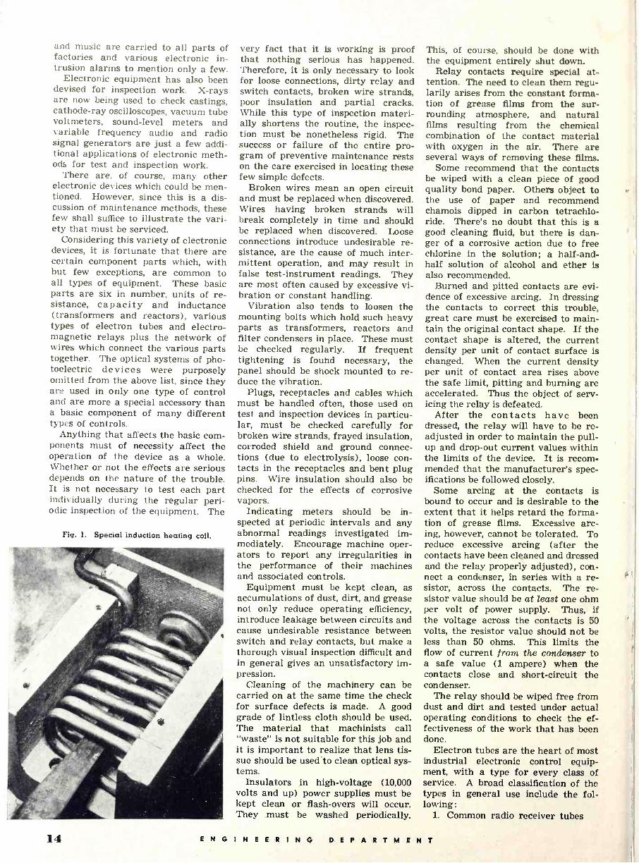
Fig. 1. Special induction heating coil.
very fact that it is working is proof that nothing serious has happened. Therefore, it is only necessary to look for loose connections, dirty relay and switch contacts, broken wire strands, poor insulation and partial cracks. While this type of inspection materi- ally shortens the routine, the inspec- tion must be nonetheless rigid. The success or failure of the entire pro- gram of preventive maintenance rests on the care exercised in locating these few simple defects.
Broken wires mean an open circuit and must be replaced when discovered. Wires having broken strands will break completely in time and should be replaced when discovered. Loose connections introduce undesirable re- sistance, are the cause of much inter- mittent operation, and may result in false test -instrument readings. They are most often caused by excessive vi- bration or constant handling.
Vibration also tends to loosen the mounting bolts which hold such heavy parts as transformers, reactors and filter condensers in place. These must be checked regularly. If frequent tightening is found necessary, the panel should be shock mounted to re- duce the vibration.
Plugs, receptacles and cables which must be handled often, those used on test and inspection devices in particu- lar, must be checked carefully for broken wire strands, frayed insulation, corroded shield and ground connec- tions (due to electrolysis), loose con- tacts in the receptacles and bent plug pins. Wire insulation should also be checked for the effects of corrosive vapors.
Indicating meters should be in- spected at periodic intervals and any abnormal readings investigated im- mediately. Encourage machine oper- ators to report any irregularities in the performance of their machines and associated controls.
Equipment must be kept clean, as accumulations of dust, dirt, and grease not only reduce operating efficiency, introduce leakage between circuits and cause undesirable resistance between switch and relay contacts, but make a thorough visual inspection difficult and in general gives an unsatisfactory im- pression.
Cleaning of the machinery can be carried on at the same time the check for surface defects is made. A good grade of lintless cloth should be used. The material that machinists call "waste" is not suitable for this job and it is important to realize that lens tis- sue should be used.to clean optical sys- tems.
Insulators in high -voltage (10,000 volts and up) power supplies must be kept clean or flash-overs will occur. They must be washed periodically.
This, of course, should be done with the equipment entirely shut down.
Relay contacts require special at- tention. The need to clean them regu- larily arises from the constant forma- tion of grease films from the sur- rounding atmosphere, and natural films resulting from the chemical combination of the contact material with oxygen in the air. There are several ways of removing these films.
Some recommend that the contacts be wiped with a clean piece of good quality bond paper. Others object to the use of paper and recommend chamois dipped in carbon tetrachlo- ride. There's no doubt that this is a good cleaning fluid, but there is dan- ger of a corrosive action due to free chlorine in the solution; a half-and- half solution of alcohol and ether is also recommended.
Burned and pitted contacts are evi- dence of excessive arcing. In dressing the contacts to correct this trouble, great care must be exercised to main- tain the original contact shape. If the contact shape is altered, the current density per unit of contact surface is changed. When the current density per unit of contact area rises above the safe limit, pitting and burning are accelerated. Thus the object of serv- icing the relay is defeated.
After the contacts have been dressed, the relay will have to be re- adjusted in order to maintain the pull- up and drop -out current values within the limits of the device. It is recom- mended that the manufacturer's spec- ifications be followed closely.
Some arcing at the contacts is bound to occur and is desirable to the extent that it helps retard the forma- tion of grease films. Excessive arc- ing, however, cannot be tolerated. To reduce excessive arcing (after the contacts have been cleaned and dressed and the relay properly adjusted), con- nect a condenser, in series with a re- sistor, across the contacts. The re- sistor value should be at least one ohm per volt of power supply. Thus, if the voltage across the contacts is 50 volts, the resistor value should not be less than 50 ohms. This limits the flow of current from the condenser to a safe value (1 ampere) when the contacts close and short-circuit the condenser.
The relay should be wiped free from dust and dirt and tested under actual operating conditions to check the ef- fectiveness of the work that has been done.
Electron tubes are the heart of most industrial electronic control equip- ment, with a type for every class of service. A broad classification of the types in general use include the fol- lowing:
1. Common radio receiver tubes
11 ENGINEERING DEPARTMENT

2. Phototubes (both high vacuum and gas filled)
3. Cathode-ray tubes 4. Thyratrons 5; Ignitrons 6. Hot -cathode (thermionic) mer-
cury-vapor rectifiers 7. High -power, forced -air draft and
water-cooled triode oscillators for induction heating equipment.
As a result of normal use, cathode emission falls off, making eventual re- placement necessary. More frequent replacements will have to be made, however, if the tubes are overloaded, operated with excessive filament volt- age or outside the intended tempera- ture limits. Today, as never before, these effects should be avoided.
Receiver type tubes require little special attention unless it is to shock mount them to eliminate vibration. Furthermore, they may be checked for emission, leakage and shorted element in any standard commercial tube tester. The other tube types listed cannot be so checked.
Phototubes gradually lose their emission and if a large number of them are used in any one plant, it is advantageous to have some means of checking them. The requirements for this testing equipment include a vari- able light source, a polarizing voltage and a vacuum tube voltmeter. All these components can be built into a single instrument so that the photo - tube can be plugged into a socket, the illumination adjusted to the minimum amount permitted in actual service and the output of the cell read on a meter in the plate circuit of the v.t.v.m.
Thyratrons are a special type of rectifier tube which operate on the principle that when the plate voltage exceeds a certain critical value, the tube begins to conduct. Once con- ducting, the grid has lost control un- til the plate voltage is removed. It is evident, therefore, that here again a special test jig is necessary to check these tubes. The characteristics to be determined are the total space cur- rent (emission) and the plate voltage necessary to "fire" the tube with a given value of grid bias. Such a test device must include in its plate cir- cuit sufficient resistance to limit the plate current to a safe value; for when the tube conducts, it becomes a short- circuit.
Cathode-ray tubes, ignitron recti- fiers and the high -power oscillator tubes will have to be checked in the equipment in which they are normally used. Tube defects will show up in faulty operation and abnormal read- ings on the associated indicating me- ters. Such a test procedure is effec- tive, however, only if the equipment, excluding the tube, is normal.
Before new thermionic (hot -cath- ode) mercury-vapor tubes can be put in service or stored, they must be pre -heated to vaporize all the mer- cury thus driving it off of the elements and into the bottom of the tube. No plate voltage is applied during this pre -heating period. The average pre- heat time is 15 to 20 minutes, although in some cases it may be advisable to preheat for as long as one hour. If the tubes are kept in storage for a period longer than 3 months, they should be pre -heated at regular inter- vals. Furthermore, they must be stored and operated in a vertical po- sition.
Application of plate voltage to a thermionic mercury-vapor rectifier be- fore it has reached normal operating temperature will damage the tube. Positive ion bombardment of the cath- ode before the space cloud has a chance to build up, will in time com- pletely destroy the cathode. It is im- perative, therefore, that the plate voltage time delay mechanism func- tion properly and be adjusted for the correct delay interval.
A periodic inspection of water cool- ing systems must be made for the purpose of detecting and removing scale formations. Chemically pure (distilled) water as the cooling agent will retard scale formation. If scale does form, and is promptly detected, it can be removed by flushing the sys- tem with a solvent such as "Oakite."
It is also essential that water tem- perature be held within the specified limits. In general, the temperature of the water leaving the tube should not be more than 10 or 15 degrees
higher than the water entering the tube. Over -cooling of mercury-vapor tubes should be avoided.
If fans are used to supplement the normal cooling methods, place them so the air blast will be distributed over the entire tube, not concentrated on one spot.
Additional hours of service from tungsten -filament tubes may be gained by operating them at slightly reduced filament voltage. It has been shown that a filament voltage reduction of only 5% doubles the life of tubes of this type. Another factor which will give extra tube life is a reduction of filament voltage to 80% of normal during standbys of less than 2 hours rather than cutting it off altogether. Every time a tube is turned on and off, the filament is weakened as it passes through the wide change in temperature.
Accurate records showing the hours of service for each type tube, other than receiving types, are extremely valuable. They not only make it pos- sible to predict with good accuracy the amount of service to be expected from any particular tube type, but form the basis from which a comparison may be made between tubes of different manu- facture. The records should show the following: (1) Type number, serial number and manufacturer; (2) date received; (3) date in service; (4) date tested; (5) date out of service and rea- son. Additional information, useful but not essential, is a list of the nor- mal operating voltages, currents and temperature.
From the foregoing, it can be seen (Continued on page 39)
Fig. 2. An industrial electronic heating unit which requires intelligent maintenance.
ENGINEERING DEPARTMENT 15

ELECTRON OPTICS
Fig. 1. Commercial electron microscopes which use principles of electron optics.
By D. FIIIEI.iiA1 Fundamental math atieal relations of electron optics applied to commeriial units using electron focussing.
ALTHOUGH electron optics is a relatively new science, in the twenty years of its existence it
has been of great importance in pro- viding the solutions to a number of problems involving the motion of elec- trons in electric and magnetic fields. Such problems are .constantly arising in all fields of radio and electronics- the cathode ray tube, electron multi- pliers, and vacuum tube design are just a few of those which have been encountered and solved by the appli- cation of electron optical principles.
The fundamental theory of electron optics is based ón Hamilton's Principle of Least Action which existed more than sixty years before the discovery that the motion of a charged particle in a field of potential, V, becomes iden- tical with the path of a light ray in an optical medium of index of refraction n, when n is set equal to V V. For instance, in Fig. 3 it can be seen how an electron beam would be refracted when going from a medium of lower to a medium of higher potential, just as a light ray is refracted when going
from a less dense to a more dense me- dium. The main point of difference between the two cases is that in optics there is almost always a distinct sur- face at which there is an abrupt change in the index of refraction, while in electron optics the potential changes gradually.
Many years later, in about 1930, it was shown that electrons on passing through an aperture in a charged con- ductor received rather sharp deflec- tions in the distorted electrostatic field. By properly choosing the geom- etry of slits and circular holes in charged plates and cylinders, the in- teraction between the distorted field and the incident electrons simulates the interaction between an optical lens and incident light rays. Fig. 4 shows the focussing action of a typical elec- tron lens compared with that of the equivalent optical lens. Many differ- ent types of electron lenses were in- vestigated in the early days of elec- tron optics, but those included in this article are of the more recent design.
In a similar manner magnetic fields can also be made to focus a beam of electrons, but in the case of a mag- netic lens the focussing action depends upon the velocity of the incident elec- trons as well as on the strength of the field, while in the electrostatic case it depends only on the field. A particle with ,charge, e, moving perpendicu- larly to a magnetic field, H, with a ve- locity, v, will have acting on it a force
F = Hey at right angles to the plane formed by the direction of motion of the particle and the direction of the magnetic field, and will therefore move in a cir- cle whose radius, R, is determined by the fact that the magnetic force must equal the centrifugal force, or
Hey = m v2/R If an electron is moving in a uniform magnetic field at an oblique angle to the direction of the field, the compo- nent of its velocity perpendicular to the field causes a circular motion while the parallel component is un- affected, and the resultant path is a spiral-all electrons having the same velocity parallel to the field return- ing to the axis at the same point, re- gardless of the value of the perpen- dicular component.
This is, however, different from the focussing action of the short magnetié
16 ENGINEER ING DEPAR TMENT
field. The electron, upon entering a short non -uniform magnetic field, is first deflected sidewise by the force due to the radial component of the magnetic field, and then moves in a helical path with slightly varying ra- dius, the inward motion being caused by the force due to the axial magnetic field and the lateral velocity. This lateral velocity decreases when the electron leaves the coil, because then the radial component is reversed and the axial speed of the electron has been maintained. The rotation has ceased when the electron has com- pletely left the magnetic field and therefore the electron passes through the axis, for if it maintained its ro- tatory motion after leaving the coil it would pass the axis without intersect- ing it. The focal length of such a magnetic field used as an electron lens is given by the relation :
f= 4m2v2
elf HZ2 dz
In general, electromagnets are pre- ferred to permanent magnets in elec- tron optical practice because the focal length of the lens can be changed merely by varying the current through the coils.
The action of both the electrostatic and magnetic electron lenses can be expressed in a single set of equations which are derived from Maxwell's equations of electromagnetic theory. By considering the motion of an elec- tron in an electromagnetic field which is symmetrical about a fixed axis, as all spherical lenses are, the equation of motion of the electron is found to be:
CO
d2z e 8 (V - e AZ dta m ez \ 2m
where: r = the distance of the particle from the
axis V = the electric potential A = the magnetic vector potential of the
field z = the distance along the axis e = the charge of the electron
m = the mass of the electron In the theory of light it is customary to consider only the so-called paraxial rays, that is, those which do not move at too great an angle to the axis, in determining the image -forming prop- erties of a lens system. Therefore, fol- lowing this same procedure for the electron lens, the path of a paraxial beam of electrons has been found to be given by the differential equation :
d2r Vo' dr 1 r( 11 2 r- 0 dt2 + 2Vo dt + 4Vo\Vo - ? where Va and Ho are the electric and magnetic field distribution along the axis of the system, and the primes represent their successive derivatives with respect to z.
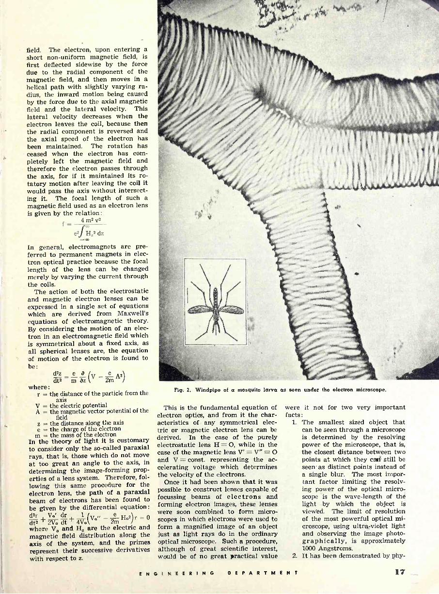
Fig. 2. Windpipe of a mosquito larva as seen under the electron microscope.
This is the fundamental equation of electron optics, and from it the char- acteristics of any symmetrical elec- tric or magnetic electron lens can be derived. In the case of the purely electrostatic lens H = O, while in the case of the magnetic lens V' = V" = O and V = const. representing the ac- celerating voltage which determines the velocity of the electrons.
Once it had been shown that it was possible to construct lenses capable of focussing beams of electrons and forming electron images, these lenses were soon combined to form micro- scopes in which electrons were used to form a magnified image of an object just as light rays do in the ordinary optical microscope. Such a procedure, although of great scientific interest, would be of no great practical value
were it not for two very important facts:
1. The smallest sized object that can be seen through a microscope is determined by the resolving power of the microscope, that is, the closest distance between two points at which they can still be seen- as distinct points instead of a single blur. The most impor- tant factor limiting the resolv- ing power of the optical micro- scope is the wave -length of the light by which the object is viewed. The limit of resolution of the most powerful optical mi- croscope, using ultra-violet light and observing the image photo- graphically, is approximately 1000 Angstroms.
2. It has been demonstrated by phy-
E N G I N E E R I N G DEPARTMENT 17
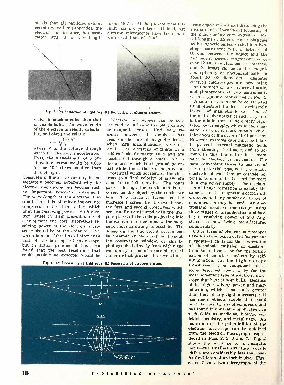
sicists that all particles exhibit certain wave -like properties, the electron, for instance, has asso- ciated with it a wave -length
(A)
Fig. 3. (a) Refraction of light ray,
which is much smaller than that of visible light. The wave -length of the electron is readily calcula- ble, and obeys the relation :
/150 A° V
where V is the voltage through which the electron is accelerated. Thus, the wave -length of a 50 - kilovolt electron would be 0.055 A°, or 10-5 times smaller than that of light.
Considering these two factors, it im- mediately becomes apparent why the electron microscope has become such an important research instrument. The wave -length of the electron is so small that it is of minor importance compared to the other factors which limit the resolving power. With elec- tron lenses in their present state of development the best theoretical re- solving power of the electron micro- scope should be of the order of 1 A°, which is about 1000 times better than that of the best optical microscope, but in actual practice it has been found that the best resolution that could possibly be expected would be
about 10 A°. At the present time this limit has not yet been attained, but electron microscopes have been built with resolutions of 20 A°.
(b) Refraction (8)
of electron stream.
Electron microscopes can be con- structed to utilize either electrostatic or magnetic lenses. Until very re- cently, however, the emphasis has been on the use of magnetic lenses when high magnifications were de- sired. The electrons originate in a cold -cathode discharge tube and are accelerated through a small hole in the anode, which is at ground poten- tial while the cathode is negative at a potential which accelerates the elec- trons to a final velocity of anywhere from 10 to 100 kilovolts. The beam passes through the anode and is fo- cussed on the object by. the condenser lens. The image is formed on the fluorescent screen by the two lenses, the first and second objectives, which are usually constructed with the iron pole pieces of the coils projecting into the vacuum in order to make the mag- netic fields as strong as possible. The image on the fluorescent screen can be observed or photographed through the observation 'window, or can be photographed directly from within the vacuum by means of a special type of camera which provides for several sep -
Fig. 4. (a) Focussing of light rays, (b) Focussing of electron stream.
arate exposures without disturbing the vacuum and allows Visual focussing of the image before each exposure. Fo- cal lengths of 0.5 cm. can be obtained with magnetic lenses, so that in a two - stage instrument with a distance of 60 cm. between the object and the fluorescent screen magnifications of over 12,000 diameters can be obtained, and the image can be further magni- fied optically or photographically to about 100,000 diameters. Magnetic electron microscopes are now being manufactured on a commercial scale, and photographs of two instruments of this type are reproduced in Fig. 1.
A similar system can be constructed using electrostatic lenses exclusively instead of magnetic lenses. One of the main advantages of such a system is the elimination of the closely regu- lated_ power supply, which in the mag- netic instrument must remain within tolerances of the order of 0.01 per cent. However, extreme care must be taken to prevent external magnetic fields from affecting the image, and to ac- complish this the entire instrument must be shielded by mu -metal. The most convenient lenses to use are of the unipotential type, with the middle electrode of each lens at cathode po- tential to eliminate the need for more than one power supply. The mechan- ism of image formation is exactly the same as in the magnetic electron mi- croscope, and any number of stages of magnification may be used. An elec- trostatic electron microscope using three stages of magnification and hav- ing a resolving power of 200 Ang- stroms is now being manufactured commercially.
Other types of electron microscopes have also been constructed for various purposes-such as for the observation of thermionic emission of electrons from hot cathodes, or for the exami- nation of metallic surfaces by self - illumination, but the high -voltage transmission type compound micro- scope described above is by far the most important type of electron micro- scope that has yet been built. Because of its high resolving power and mag- nification, which is so much greater than that of any light microscope, it has made objects visible that could never be seen by any other means, and has found innumerable applications in such fields as medicine, biology, col- loidal chemistry, and metallurgy. An indication of the potentialities of the electron microscope can be obtained from the electron micrographs repro- duced in Figs. 2, 5, 6 and 7. Fig. 2 shows the windpipe of a mosquito larva-the smallest structural details visible are considerably less than one- half millionth of an inch in size. Figs. 6 and 7 show two micrographs of the
18 ENGINEERING DEPARTMENT

tobacco mosaic virus, and in Fig. 5 is reproduced the first photograph ever taken of the influenza virus.
Many of the electronic instruments in widespread use have been developed by the direct application of electron optical principles. Probably the best- known of these is the electron gun, which has made possible the develop- ment of the cathode ray tube, the Kinescope, and the Iconoscope. Ref- erence to Fig. 8 will make clear the electron optical behavior of the elec- tron gun. The electrons are emitted by the cathode and focussed into a small spot, or "cross -over," by the im- mersion lens formed by the grid and the first anode; the grid, in addition, serves to control the electron density of the beam, and hence the brightness of the spot. The second lens, formed by the first and second anodes, focuses the images of the cross -over to form the bright spot on a fluorescent screen.
The cathode ray tube and the Kine- scope consist essentially of an electron gun followed by horizontal and verti- cal deflecting fields by means of which the pattern is formed on the fluores- cent screen. These deflecting fields may be either electrostatic, magnetic, or a combination of both. In the Iconoscope a photosensitive mosaic takes the place of the fluorescent screen, and the electron beam is scanned across the mosaic by the de- flecting fields. Although the three tubes are used for different purposes, their electron optical systems are identical.
A more striking example, from the electron optical viewpoint, is the "image dissector," a television pickup used mainly in the televising of mo- tion picture films. The scene which is to be transmitted is focussed optically onto a translucent cathode which is coated with photosensitive material so that from each spot on the cathode surface is emitted a quantity of elec- trons proportional to the amount of light falling on the surface at that point. These electrons are attracted by the anode, which is at a positive potential with respect to the cathode, and by means of the magnetic lens the electron image is focussed on the. an- ode so that all the electrons emitted from a single point on the cathode con- verge to a single point in the anode plane. The anode contains an aper- ture behind which a collector elec- trode is placed in such a manner that all the electrons which happen to be focussed on the aperture pass through the anode and strike the collector. Thus a current is produced through the load resistor which is proportional to the number of electrons focussed on
the aperture, and therefore propor- tional to the intensity of the light at
(Continued on page 44) -
Fig. 5. First photograph of the influenza virus with scale of one inch to onehalf micron.
Fig. 6. Photograph of tobacco mosaic virus obtained with an electron microscope. The slide was placed in an evacuated chamber of the microscope and pierced by high velocity electrons.
Fig. 7. Highly magnified electron photomicrograph of tobacco virus attacked by antibodies.
ENGINEERING DEPARTMENT 1"

Impedance Nomogram By B. S. BRANCH Engineer
A graphical method of evaluating the series complex imped- ance of a resistance and reactance connected in parallel.
HE problem of calculating the equivalent impedance of a re- sistance and a reactance in par-
allel is frequently encountered in com- munication network design. The use of a polyphase or vector slide rule has simplified to a minor extent the nec- essary calculations required to give the final numerical answer. These calculations, involving complex num- bers, must give two quantities in order to specify the answer. The magnitude of the impedance as well as the angle of the impedance must be obtained to determine completely the impedance of the parallel combination. The ac- companying chart on the next page provides a means of obtaining the magnitude and phase angle of the parallel circuit. The theory involved in this calculation, using complex numbers, is outlined below.
First consider the shunt reactance to be an inductive reactance. The ex- pression for the impedance will be given by Z as:
1 1 1
Z R+jX Then solving for Z
(1)
Z = lRX
(2) R + jX
and rationalizing the fraction gives:
RX2 z
Z R2 + X2 j R (3)
Then:
Z= 1Z1/+0 (4)
Where:
IZI = (( 11
V1+\XJz and
R
9 = tan -1 (X/
(5)
(6)
Now consider the shunt reactance to be a capacitive reactance and the
expression for the impedance will be given by:
1 _1 1 Z-R+-jX By solving for Z :
- j RX Z R - iX
and rationalizing the Z in the complex form:
(7)
= RX2 jR2X
Then
(8)
fraction, gives
(9)
(10)
(11)
R2 + X2 R2 + X2
Z= IZI/-e Where:
and
Z 1 =
r( l¡
V1 +\X21
R
e = tan --1(R X) (12)
This analysis shows that the angle of the impedance is positive when the shunting reactance is inductive and negative when the shunting reactance is capacitive.
The theory of constructing the three parallel line nomogram is based upon the procedure outlined on page 12 of the December issue of Radionics in an article by S. Klapman entitled "Nomo- gram Construction." From this arti- cle, "The general construction of a nomogram, as presented is based upon the fundamental necessary and suffi- cient condition for three points (x1,
'1) (x2, y2) and (x3, ya) to lie on a straight line as shown by the determi- nant :"
xn Yn 1 X2 Y2 1 = 0 (13) XE Y3 1
If the scales are vertical and paral- lel, let, x1 = -1, x2 = 0 and x3 = +1 and y1 y2, and y3 will become functions
of the variables. This is expressed al- gebraically as:
yi = fn (u) Y2 = - á f2 (y)
> (14,
Ys = fa (w)
The determinant becomes:
- 1 yl 1
O Y2 1 ( = 0 1 ya 1
or:
(15)
Yi - 2 Y2 + Ya = 0 (16J
To obtain a relation between X, R, and R/X in the determinantal form, consider:
cotana K =X = (17)
or:
K ..1K
Then: - log R + log X + log K = or:
R 1
0 - 1. log X 1 .. 1t) 1 log K 1
The determinant indicates that the first vertical line will have a scale marked proportionally to - log R and the second line will have a scale of -1/2 log X while the third will be scaled proportionally to log K. Notice that the scales of the first two lines are in the inverse order, that is, the numbers decrease along the upward direction and the scale along the third lines increases in the upward direction. Also, the scales of R and K are geo- metrically twice as long as that of X. By connecting any three points on the three parallel lines with a straight- edge, the three points are related in accordance with equation (17). Thus, the nomogram must be constructed as indicated by (19).
With the aid of the accompanying nomogram, equations (5), (6), (11) and (12) are solved graphically.
(Continued on page 46)
20 ENGINEERING DEPARTMENT

o o _ U
,I)
N - fl.l
O m
O I I X l _ il
oO , OÓ Q-. ''
0o w
,00 P
. SO
u>
000
w
O z iß º ao
aw
oo P` ' U I o r,AÌAr 00 P,6
"1 OO a'`'
p00 a°
IIIIIIIIIIIP- / ° "S0°>'
W
ó
R=100 w
0
m
I
. r I
b b b r } Il
Yl
I jJJ,J,,,J1J? 1 1
S332:1930 N1
b e
1 J 1111 t ` 1 1 1
A
b ° M
¡¡I { /I `
-
1
t ' J ``
44 I Í II I II1f1r1111
e
¡¡ f 1 I I
o o - N N1
I I
o
I I
o e
I
o N 1U
y
o o o o o 1` co 01 o -
I
SWHO
h I I9 I Ir I
x/a
- 33NV13V3a 0 o N
I o
o o N1
I Ii,I,
o o e
I
v
o o o
I
I I
i
I I o o o
IIIIi
I t I
n
i
I N
0 o O N
l i
I 111
o o o M
I i
o o o e
I
I 1 i
0 o o ,
o N
I I II{IIiII
Ó
I
o
I I
O 0
I I
O n
I I I
O m
IIII{II
O 01
I I I I IIIiI
SWHO - 3ONV1SIS3a O _O
I I
o
I I I I¡I IIIlllilllli
O ñ
p o ln
I
o
f
oo
f
o m °
I I I I I I l' i I I I I I I I E f I f l I IIIIHI
z
0
ENGINEERING DEPARTMENT 21
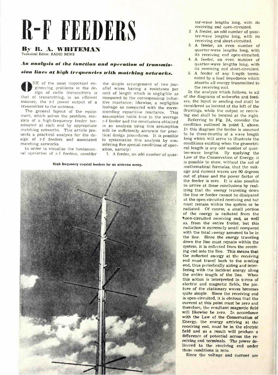
It -F FEEDERS By H. A. WHITEMAN Technical Editor. RADIO NEWS
An analysis of the function and operation of transmis- sion lines at high frequencies with matching networks.
ONE of the most important en- gineering problems in the de- sign of radio transmitters is
that of transmitting, in an efficient manner, the r -f power output of a transmitter to the antenna.
The general layout of the equip- ment, which solves the problem, con- sists of a high -frequency feeder ter- minated at each end by appropriate matching networks. This article pre- sents a practical analysis for the de- sign of r -f feeders and associated matching networks.
In order to visualize the fundamen- tal operation of r -f feeders, consider
the simple arrangement of two par- allel wires having a resistance per unit of length which is negligible as compared to the corresponding induc- tive reactance; likewise, a negligible leakage as compared with the corre- sponding capacitive reactance. This assumption holds true in the average r -f feeder and the conclusions obtained in an analysis using this assumption will be sufficiently accurate for prac- tical design procedures. It is possible to systematize this analysis by con- sidering five special conditions of oper- ation, namely:
1. A feeder, an odd number of guar -
High frequency coaxial feeders for an antenna array.
ter -wave lengths long, with its receiving end open -circuited.
2. A feeder, an odd number of quar- ter -wave lengths long, with its receiving end short-circuited.
3. A feeder, an even number of quarter -wave lengths long, with its receiving end open -circuited.
4. A feeder, an even number of quarter -wave lengths long, with its receiving end short-circuited.
5. A feeder of any 1:ngth termi- nated by a load impedance which absorbs all energy transmitted to the receiving end.
In the analysis which follows, in all of the diagrams of networks and feed- ers, the input or sending end shall be considered as located at the left of the drawings, while the output or receiv- ing end shall be located at the right.
Referring to Fig. 2A, consider the condition outlined in point 1, above. In this diagram the feeder is assumed to be three -fourths of a wave length long which will serve to illustrate the conditions existing when the geometri- cal length is any odd number of quar- ter -wave lengths. By applying the Law of the Conservation of Energy, it is possible to show, without the aid of mathematical formulas, that the volt- age and current waves are 90 degrees out of phase and the power factor of the feeder is zero. It is also possible to arrive at these conclusions by real- izing that the energy traveling down the line or feeder cannot be dissipated at the open -circuited receiving end but must remain within the system or be radiated. Of course, a small portion of the energy is radiated from the bpen-circuited receiving end, as well as, from the entire feeder, but this radiation is extremely small compared with the total energy assumed to be in the line. Since the energy traveling down the line must remain within the system, it is reflected from the receiv- ing end into the line. This means that the reflected energy at the receiving end must travel back to the sending end, thus periodically aiding and inter- fering with the incident energy along the entire length of the line. When this action is interpreted in terms of electric and magnetic fields, the pic- ture of the stationary waves becomes quite simple. Since the receiving end is open -circuited, it is obvious that the current at this point must be zero and therefore, the resultant magnetic field will likewise be zero. In accordance with the Law of the Conservation of Energy, the energy arriving at the receiving end, must be In the electric field and as a result will produce a difference of potential across the re- ceiving end terminals. The power de- livered to the receiving end under these conditions is zero.
Since the voltage and current are
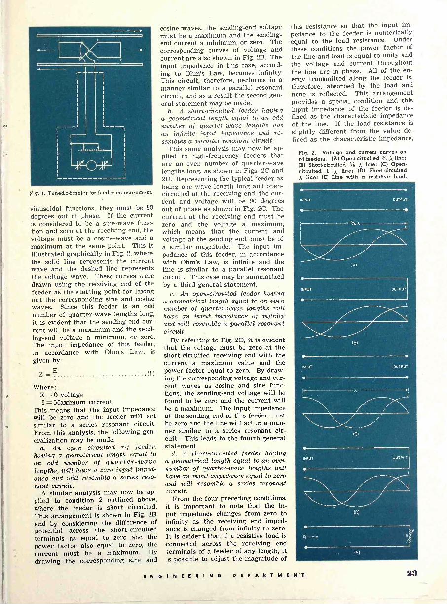
Fig. 1. Tuned r -f meter for feeder measurement.
sinusoidal functions, they must be 90 degrees out of phase. If the current is considered to be a sine -wave func- tion and zero at the receiving end, the voltage must be a cosine -wave and a maximum at the same point. This is illustrated graphically in Fig. 2, where the solid line represents the current wave and the dashed line represents the voltage wave. These curves were drawn using the receiving end of the feeder as the starting point for laying out the corresponding sine and cosine waves. Since this feeder is an odd number of quarter -wave lengths long, it is evident that the sending -end cur- rent will be a maximum and the send- ing -end voltage a minimum, or zero. The input impedance of this feeder, in accordance with Ohm's Law, is
given by:
Z = E (1)
Where :
E = 0 voltage I = Maximum current
This means that the input impedance will be zero and the feeder will act similar to a series resonant circuit. From this analysis, the following gen- eralization may be made.
a. An open circuited r -f feeder, having a geometrical length equal to an odd number of quarter -wave lengths, will have a zero input imped- ance and will resemble a series reso- nant circuit.
A similar analysis may now be ap- plied to condition 2 outlined above, where the feeder is short circuited. This arrangement is shown in Fig. 2B
and by considering the difference of potential across the short-circuited terminals as equal to zero and the power factor also equal to zero, the current must be a maximum. By drawing the corresponding sine and
cosine waves, the sending -end voltage must be a maximum and the sending - end current a minimum, or zero. The corresponding curves of voltage and current are also shown in Fig. 2B. The input impedance in this case, accord- ing to Ohm's Law, becomes infinity. This circuit, therefore, performs in a manner similar to a parallel resonant circuit, and as a result the second gen- eral statement may be made.
b. A short-circuited feeder having a geometrical length equal to an odd number of quarter -wave lengths has an infinite input impedance and re- sembles a parallel resonant circuit.
This same analysis may now be ap- plied to high -frequency feeders that are an even number of quarter -wave lengths long, as shown in Figs. 2C and 2D. Representing the typical feeder as being one wave length long and open - circuited at the receiving end, the cur- rent and voltage will be 90 degrees out of phase as shown in Fig. 2C. The current at the receiving end must be zero and the voltage a maximum, which means that the current and voltage at the sending end, must be of a similar magnitude. The input im- pedance of this feeder, in accordance with Ohm's Law, is infinite and the. line is similar to a parallel resonant circuit. This case may be summarized by a third general statement.
c. An open -circuited feeder having a geometrical length equal to an even number of quarter -wave lengths will have an input impedance of infinity and will resemble a parallel resonant circuit.
By referring to Fig. 2D, it is evident that the voltage must be zero at the short-circuited receiving end with the current a maximum value and the power factor equal to zero. By draw- ing the corresponding voltage and cur- rent waves as cosine and sine func- tions, the sending -end voltage will be found to be zero and the current will be a maximum. The input impedance at the sending end of this feeder must be zero and the line will act in a man- ner similar to a series resonant cir- cuit. This leads to the fourth general statement.
d. A short-circuited feeder having a geometrical length equal to an even number of quarter -wave lengths will have an input impedance equal to zero and will resemble a series resonant circuit.
From the four preceding conditions, it is important to note that the in- put impedance changes from zero to infinity as the receiving end imped- ance is changed from infinity to zero. It is evident that if a resistive load is connected across the receiving end terminals of a feeder of any length, it is possible to adjust the magnitude of
this resistance so that the. input im-
pedance to the feeder is numerically equal to the load resistance. Under these conditions the power factor of the line and load is equal to unity and the voltage and current throughout the line are in phase. All of the en- ergy transmitted along the feeder is,
therefore, absorbed by the load and none is reflected. This arrangement provides a special condition and this input impedance of the feeder is de- fined as the characteristic impedance of the line. If the load resistance is slightly different from the value de- fined as the characteristic impedance,
Fig. 2. Voltage and current curves on r -f feeders. (A) Open -circuited 3/A Á line; (B) Short-circuited 3/4 ñ line; (C) Open - circuited 1 X line; (D) Short-circuited
line; (E) Line with a resistive load..
ENGINEERING D E P A R T M E N'T 23

all of the energy supplied to the line will not be absorbed by the load, but a portion of the incident energy will be reflected. If the line is being used
Fig. 3. Coaxial lins with insulator.
for the purpose of supplying r -f power, the ideal conditions would be that of total absorption and zero reflection at the receiving end. In practice, this is not physically possible, but a reflec- tion of approximately 5% of the inci- dent voltage is considered to be satis- factory. It appears from this analysis that there are a number of different applications of r -f feeders other than that of transmitting maximum r -f power. The properties of resonant cir- cuits which have been mentioned are used in replacing coil and condenser tank circuits with short-circuited lines an odd number of quarter -wave lengths long. This application is a special case of the more general clas- sification listed as if5 in this article.
The foregoing qualitative discussion may be verified analytically by using the impedance formula for the dissi- pationless r -f feeder. The formula is expressed as:
=Zrcosßl+jZosinßl Z, cos ßl + j Zr sin ßl' (2)
Where :
Z. = characteristic impedance Z,.= receiving -end impedance ß = phase constant 1= length of line j = V -1
As an illustrative example, apply equation (2) to condition #1 above. The values of the quantities in the formula become:
Zr = CO
ßl = 4 an odd number.
Since Z,. appears in the numerator of (2), divide the numerator and de- nominator by Zr which gives the re- lation :
Fig. 4. Basic T matching network.
cos jZr sin ß1
Zt=Za Zr oos ßl + j sin ßl
and then:
O --I-.0 j
=Z°0+1 Zi = 0
(3)
This justifies statement a analyti- cally and a similar procedure may be used to justify the remaining state- ments.
If the short-circuited or open -cir- cuited lines are not an exact multiple of a quarter -wave length, the input impedance will be either inductive or capacitive. Again with (2), consider the length of the line slightly more than a quarter of a wavelength with the receiving -end open -circuited. The quantities in the formula become :
Zr = CO
ßl=4 -{- and the input impedance from (3) is:
(à)
')35°M111111111111.1111.1111 3
fflj`lettillaillM M 250
200_``'rM==elgim ''...=- Ioo/,
11.1111.111150' 0.5 10 1.5 2.0 2.5 3.0 3.5 4.0 4.5 5.0
RATIO d/b
(B)
Fig. 5. (A) Geometrical arrange- ment of a four wire feeder; (B) Im- pedance in ohms of four wire line.
Zr=Zo -A+jO 0 j or:
Zt=jAB°
(5)
(6)
Equation (6) shows that the input impedance is an inductive reactance and is quantitatively related to the geometrical length. If, however, the length were slightly less than a quar-
ter -wave the input impedance would be:
A + j0 Zi
Z°0 + iB
or:
zr-j B°
(7)
(8)
Equation (8) shows that the input impedance would be a capacitive re- actance and equal in magnitude to that given by formula (6).
The practical application of using r -f feeders as inductances or capaci- tances will be included in the latter portions of this article.
The use of the high -frequency feeder as a means of transferring r -f power to a load, such as an antenna, has been outlined In condition #5 above. To de- termine the percentage of the incident voltage or current which is reflected at a slightly mismatched receiving end, a method of measuring the rela- tive magnitude of the maximum and minimum current is necessary. The ratio of these two numerical quanti- ties is defined as the standing -wave ratio and is generally expressed as a number greater than unity. If this ratio is represented as S, the coeffi- cient of reflection for the current or voltage wave is
S - 1 (9) k =S+1
and that for energy is:
(S -1\z k2 -
\S + 1J (10)
A very accurate procedure for measuring S includes an arrangement such as that shown in Fig. 1, which is designed to absorb r -f energy based upon electromagnetic induction. This is accomplished by using two pickup coils connected in parallel, the output of which is connected through a screened line to a thermogalvanom- eter. The scale reading of the gal- vanometer will be proportional to the inducing magnetic field and therefore to the current in the r -f feeder. If some reflection exists at the receiving end, there will be a traveling wave as well as a stationary wave and S will be greater than unity. If, however, there is no reflection, as for ideal con- ditions, the traveling wave will exist alone and S will equal unity. By ad- justing the matching networks at the terminations of the line, the numerical value of S may be reduced to a satis- factory minimum of 1.05.
Of the various possible types of feeders that may be used the coaxial line, the two -wire and four -wire line are the most practical. Coaxial lines are constructed in the rigid as well as the semi -flexible form for transmit -
21 ENGINEERING DEPARTMENT

ting purposes and have the chief ad- vantage of low attenuation and negli- gible radiation loss. The internal con- struction of the coaxial line is shown in Fig. 6 and the characteristic im- pedance is: a
Z. = 138 log' b (11) -e,/1+(E-1)t
Where : d a = radius of outer conductor b = radius of inner conductor
e = dielectric constant of insulating material
t = thickness of dielectric insulator d = distance between dielectric in-
sulators When constructing or purchasing
this type of line, it is important to realize that the maximum potential gradient between the inner conductor and the outer conductor occurs at the surface of the inner conductor. This is due to the air layer between the insulators and the outer conductor, since the air layer has a lower dielec- tric constant than the insulation ma- terial. This means that the insulators must fit very tightly against the inner conductor in order to minimize the po- tential gradient at the inner conductor surface.
The two -wire line, as an r -f feeder, is extremely useful but has a few un- desirable characteristics which must be avoided when possible. The rela- tively high characteristic impedance for this type of line is illustrated in Fig. 7 which necessitates proper matching with the load impedance.
The two -wire line should be care- fully checked for balanced r -f currents in order to reduce radiation and losses. Frequently there are stationary waves partially displaced along each line due to unbalanced reflection at the sup- porting insulators and not due to a mismatched load.
A more practical layout for higher powers is that of a four -wire r -f feeder with the conductors arranged to form a rectangle. The conductors, located at the ends of the diagonal, are con- nected together thereby giving a lower characteristic impedance and a lower line voltage for a given power.
Smaller sized wires may be used in order to handle the r -f power. This is exemplified by a four -wire feeder us- ing No. 6 gauge wire to carry 100 kw. Fig. 5 provides graphs for evaluating the characteristic impedance of a four -
Fig. 6. Cross section of coaxial line.
500 ln E=E=EEE°ÉÉEEEEEE éé?É5'2e" é ÉéSi::. r
M. =Oman: CCCC: a-OT :77 - i: :": I :ill H i"' g
E° E 7 aa:á:B°. E It
EEEEEEt;sEeeBefieEEº7 -E7::1::?:31 :. :iii '°(Eoo -ga o- e -g- :gE-::::::r.:: pe»-- EEEEEEEECélie?EEE,.Eá=i)
_ E6ggeE=aEEfieE -ªg jEª7:...i:;elie.; ¡ --
EEEEBE9àEEEse.. árriíENi p 600 C1Oy% G tlt -" ,,, i
15.0
E O =0 P N, OIN®..l:if!u11M1 -iwair® _ H ._ -_.- ._ S-
.No Af O 4 lo P',.J. r . .
ff
900 Iiiiii I . O/p.-r -11 (tii:,.. ' tl s "0.1. A9@EEE6EEE T EE .
_EËRE1EE1ggggEEE1111llliiH - 300 2 3 9
S -_'PACING FROM CENTER TO CENTER IN INCHES
Fig. 7. Characteristic impedance of two -wire line as a function of spacing.
wire line for different spacings. In order to match the impedance of
the antenna to the line, several types of networks are available. Realizing that these circuits must be four -ter- minal networks with an input and an output, one basic requirement must be satisfied if lumped parameters are used. Since the r -f power at one fre- quency or a narrow band of frequen- cies is transferred to the antenna for radiation purposes, all harmonics of this frequency should be suppressed. The matching network under these conditions should contain a shunt ca- pacitive reactance to by-pass the har- monic frequencies.
The three -element coupling or matching network is one of the most valuable types of network used. The elements may be arranged for a TT or a T network with three variables con- trolling the three quantities, input re- sistance and reactance and the phase shift through the network. The phase shift is important for maintaining the proper phase relationship of the an- tenna currents in a directional -an- tenna array as outlined in the article entitled "Antenna Performance" by John Barron in the March issue of Radio -Electronic Engineering.
The equations for the design of a general T network as shown in Fig. 4 are:
7, ZII cosh e - ZI, Zi sink e
12
Z2 = ZI2 cosh e -J Z,1 ZI2
(131 Binh B
ZI, ZI2 (14 Z, - sinh t7
Where :
Z11 = image impedance minais 1 and 2
Z12 = image impedance minais 3 and 4
= image transfer a + Jß
across ter -
across ter -
constant =
a = attenuation constant in db. ß = phase shift in radians.
It is possible to simplify the general formulas so that they apply to a more special case, that is, for a network where:
Z=R, ZI2 = R2
0=1ß Equations (12), (13) and (14) re-
duce to:
Z R, cos ß- RI R2
sin ß
z2= -.R2 COS ß-1(RIR2 sin ß
(15)
(16)
73 - ¡ RI R2 (17) sin ß
The three quantities R,, 11.2, and ß
are independent and by selecting vari- ous values ß it is possible to obtain a variety of T matching networks all of which match R2 to R, with different values of Z1, Z2, and Z3. There is a special simplified procedure for de- signing matching networks for a sin- gle antenna load. The phase angle of the antenna current is selected as 90 degrees and equations (15), (16) and (17) become:
ZI = J R, R2. (181
Z2=l RI R2 (191
Za = - J 1.7 RI R2 (201
The fact that Z, and Z2 are induct- ances of equal reactance and Z3 is a capacitive reactance equal in magni- tude to Z greatly simplifies the selec- tion of component parts for the match- ing networks.
Instead of assigning a numerical value to ß, it is possible to assign a value to Z1, Z2, or Z, and compute the resulting value of ß that must be used. Since the antenna impedance gener-
(Continued on page 41)
ENGINEERING DEPARTMENT 25

Cathode -Ray Television Tubes 11y 1I:111tItY D. II111/'l'111 Engineer, Philco Television Corp.
The structure and operation of cathode-ray tubes which form an essential part of modern television systems. IMM1111131M1mi,
,LECTF, RONIC television had
made rapid advancement up to the time of our entry into the
war. Today, as in the case of other activities not essential to the prosecu- tion of the war, television progress, as such, has been halted for the dura- tion. Most of the television station li- censees are broadcasting video pro- grams only for the minimum number of hours per week necessary to retain their station licenses. However, re- search and development in closely al- lied fields, accelerated by war -time necessity, are doing much to assure television a prominent place in the scheme of things after the cessation of hostilities. The cathode-ray tube, once the most expensive part in the television receiver, is no longer a laboratory product; it is being turned out by mass production methods and in enormous quantities, almost as eas- ily as were the ordinary glass and metal receiving tubes of a few years ago. Many new uses for television and television techniques will be found, probably as a direct result of the war.
Basically, the cathode-ray tube is quite simple, consisting of three essen- tial parts: an electron gun for produc- ing a narrow beam of rapidly moving electrons, known as "cathode rays";
a fluorescent screen which produces a luminous spot as a result of the cathode ray bombardment; and some means of deflecting or moving the lu- minous spot to any desired position on the screen. The drawing, Fig. 3, shows the general arrangement of the electrodes in both the magnetic -de- flection, electrostatic -focus and elec- trostatic -deflection, electrostatic -focus types. It will be noticed that elec- trodes K, G, H, F and A constitute the electron gun or electron -optical system by means of which the electrons, emitted by the thermionic cathode, are concentrated into an intense, nar- row beam. The gun is located in the narrow neck of the pear-shaped main body of the tube envelope, directly op- posite the slightly curved broad end, upon the inside surface of which is placed the fluorescent material.
The fluorescent material, of which the screen is composed, glows under the intense electron bombardment and the spot is visible to the eye as a bright point of light. If the intensity of the beam is varied, the amount of light emitted at the spot will also vary. In actual practice the current in the beam and therefore, the amount of visible light emitted is varied by ap- plying a potential to the control grid of the electron gun.
By means of a set of electromag- netic deflection coils or a set of elec- trostatic deflection plates (Fig. 313). the spot may be moved to any desired position on the screen. In a modern television system the spot is caused to sweep across the screen in a series of straight, parallel lines, which are required for the scanning pattern, by means of suitably varying currents or potentials applied to the deflection electrodes. The electron beam is caused to sweep out the scanning pat- tern at such a tremendous rate that, due to the persistence of vision, the pattern appears to be stationary. If the screen is examined closely, how- ever, the finely grained lines can be seen but, like the motion picture screen, at a short distance away the video screen appears to be uniformly luminous.
As the cathode-ray tube is the heart of the television system, so is the elec- tron gun the heart of the cathode-ray tube. Two types of gun structures are generally employed, the magnetic fo- cusing type, which has not been used to any great extent in this country, but is rapidly becoming more popular because of its ruggedness and struc- tural simplicity, and the electrostatic focusing type.
A typical gun structure is illustrated
Fig. 1. Television scanning method in general use at present time. (A) Return path of scanning beam. (B) Pattern for interlaced scanning.
26 ENGINEERING DEPARTMENT
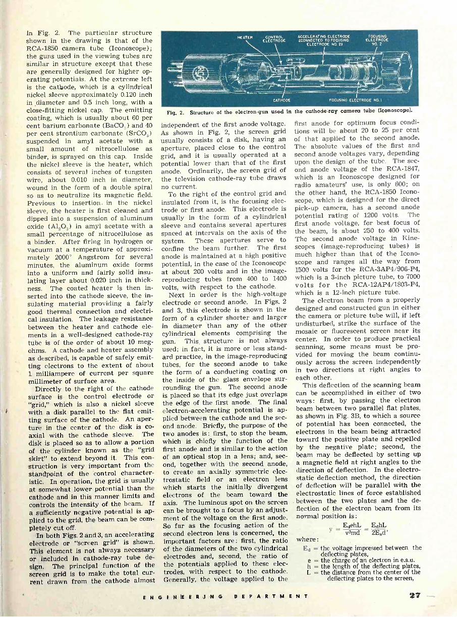
In Fig. 2. The particular structure shown in the drawing is that of the RCA -1850 camera tube (Iconoscope); the guns used in the viewing tubes are similar in structure except that these are generally designed for higher op- erating potentials. At the extreme left is the cathode, which is a cylindrical nickel sleeve approximately 0.120 inch in diameter and 0.5 inch long, with a close -fitting nickel cap. The emitting coating, which is usually about 60 per cent barium carbonate (BaCO3) and 40 per cent strontium carbonate (SrCO3) suspended in amyl acetate with a small amount of nitrocellulose as binder, is sprayed on this cap. Inside the nickel sleeve is the heater, which consists of several inches of tungsten wire, about 0.010 inch in diameter, wound in the form of a double spiral so as to neutralize its magnetic field. Previous to insertion. in the nickel sleeve, the heater is first cleaned and dipped into a suspension of aluminum oxide (A1203) in amyl acetate with a small percentage of nitrocellulose as a binder. After firing in hydrogen or vacuum at a temperature of approxi- mately 2000' Angstrom for several minutes, the aluminum oxide forms into a uniform and fairly solid insu- lating layer about 0.020 inch in thick- ness. The coated heater is then in- serted into the cathode sleeve, the in- sulating material providing a fairly good thermal connection and electri- cal insulation. The leakage resistance between the heater and cathode ele- ments in a well -designed cathode-ray tube is of the order of about 10 meg- ohms. A cathode and heater assembly as described, is capable of safely emit- ting electrons to the extent of about 1 milliampere of current per square millimeter of surface area.
Directly to the right of the cathode surface is the control electrode or "grid," which is also a nickel sleeve with a disk parallel to the flat emit- ting surface of the cathode. An aper- ture in the center of the disk is co- axial with the cathode sleeve. The disk is placed so as to allow a portion of the cylinder known as the "grid skirt" to extend beyond it. This con- struction is very important from the standpoint of the control character- istic. In operation, the grid is usually at somewhat lower potential than the cathode and in this manner limits and controls the intensity of the beam. If a sufficiently negative potential is ap- plied to the grid, the beam can be com- pletely cut off.
In both Figs. 2 and 3, an accelerating electrode or "screen grid" is shown. This element is not always necessary or included in cathode-ray tube de- sign. The principal function of the screen grid is to make the total cur- rent drawn from the cathode almost
HEATER CONTROL ELECTRODE
CATHODE
ACCELERATING ELECTRODE (CONNECTED TO FOCUSING
ELECTRODE NO. 2)
FOCUSING ELECTRODE
NO. 2
FOCUSING ELECTRODE NO.1
Fig. 2. Structure of the electron -gun used In the cathode=ray camera tube (Iconoscope).
independent of the first anode voltage. As shown in Fig. 2, the screen grid usually consists of a disk, having an aperture, placed close to the control grid, and it is usually operated at a potential lower than that of the first anode. Ordinarily, the screen grid of the television cathode-ray tube draws no current.
To the right of the control grid and insulated from it, is the focusing elec- trode or first anode. This electrode is usually in the form of a cylindrical sleeve and contains several apertures spaced at intervals on the axis of the system. These apertures serve to confine the beam further. The first anode is maintained at a high positive potential, in the case of the Iconoscope at about 200 volts and in the image - reproducing tubes from 400 to 1400
volts, with respect to the cathode. Next in order is the high -voltage
electrode or second anode. In Figs. 2
and 3, this electrode is shown in the form of a cylinder shorter and larger in diameter. than any of the other cylindrical elements comprising the gun. This. structure is not always used; in fact, it is more or less stand- ard practice, in the image -reproducing tubes, for the second anode to take the form of a conducting coating on the inside of the glass envelope sur- rounding the gun. The second anode is placed so that its edge just overlaps the edge of the first anode. The final electron -accelerating potential is ap- plied between the cathode and the sec- ond anode. Briefly, the purpose of the two anodes is : first, to stop the beam, which is chiefly the function of the first anode and is similar to the action of an optical stop in a lens; and, sec- ond, together with the second anode, to create an axially symmetric elec- trostatic field or an electron lens which starts the initially divergent electrons of the beam toward the axis. The luminous spot on the screen can be brought to a focus by an adjust- ment of the voltage on the first anode. So far as the focusing action of the second electron lens is concerned, the important factors are : first, the ratio of the diameters of the two cylindrical electrodes and, second, the ratio of the potentials applied to these elec- trodes, with respect to the cathode. Generally, the voltage applied to the
first anode for optimum focus condi- tions will be about 20 to 25 per cent of that applied to the second anode. The absolute values of the first and second anode voltages vary, depending upon the design of the tube. The sec- ond anode voltage of the RCA -1847, which is an Iconoscope designed for radio amateurs' use, is only 600; on the other hand, the RCA -1850 Icono- scope, which is designed for the direct pick-up camera, has a second anode potential rating of 1200 volts. The first anode voltage, for best focus of the beam, is about 250 to 400 volts. The second anode voltage in Kine- scopes (image -reproducing tubes) is much higher than that of the Icono- scope and ranges all the way from 1500 volts for the RCA-3AP4/906-P4, which is a 3 -inch picture tube, to 7000 volts for the RCA-12AP4/1803-P4, which is a 12 -inch picture tube.
The electron beam from a properly designed and constructed gun in either the camera or picture tube will, if left undisturbed, strike the surface of the mosaic or fluorescent screen near its center. In order to produce practical scanning, some means must be pro- vided for moving the beam continu- ously across the screen independently in two directions at right angles to each other.
This deflection of the scanning beam can be accomplished in either of two ways : first, by passing the electron beam between two parallel flat plates, as shown in Fig. 3B, to which a source of potential has been connected, the electrons in the beam being attracted toward the positive plate and repelled by the negative plate; second, the beam may be deflected by setting up a magnetic field at right angles to the direction of deflection. In the electro- static deflection method, the direction of deflection will be parallel with the electrostatic lines of force established
. between the two plates and the de- flection of the electron beam from its normal position is:
EdehL EdhL - Yv2md 2Ead' where :
Ed = the voltage impressed between the deflecting plates,
e = the charge of an electron in e.s.u. h = the length of the deflecting plates, L = the distance from the center of the
deflecting plates to the screen,
ENGINEERING DEPARTMENT 27

v = the electron velocity in cm/sec m = the mass of the electron, d = the separation of the deflecting
plates, Ea = the potential of the second anode
relative to the cathode. Ed and Ea are in the same units as h, L, d and y.
The deflection of the electron beam produced by a magnetic field will be at right angles to that field and is gen- erally given by the expression:
y = 0.297 LsB ,
,/ fia where:
L = the distance in centimeters between the screen and the point where electrons enter the field,
s = the distance in centimeters over which the deflecting field acts,
B = the flux density in gauss, Ea = the second anode voltage. The two expressions show that, for
electrostatic deflection, the beam dis- placement is directly proportional to the deflecting voltage and inversely proportional to the second anode po- tential. For magnetic deflection, the beam displacement is proportional to field strength, which is in turn propor- tional to the coil current.
In general cathode-ray tubes that are designed for electrostatic deflec- tion are also electrostatic focusing; tubes that use magnetic deflection gen- erally use magnetic focusing. The principal advantage of magnetic fo- cusing is, of course, in the simplifica- tion of the electron gun design. Other advantages are the lower cost and general ruggedness of the assembly. The advantage of the electrostatic method of focusing and deflection is that it requires little or no current and therefore draws a negligible amount of power from the source. The associated circuits are much simpler
and inductance troubles are avoided. A television image is "scanned" in
almost the same manner as that in which a reader scans a page of printed material. The eye begins at the up- per left corner of the page and slowly traverses the first printed line until the extreme right edge of the page is reached. At this point the eye quickly reverses its motion and returns to the left edge of the page and the beginning of the second line. The slower left -to - right motion is again resumed and each line is scanned in its turn until the page is completed.
In a modern television system, a scanning technique known as "inter- lacing" is employed in order to reduce flicker in the reproduced image. In this method the image is scanned in two or more groups of lines. Fig. lb shows the scanning system now in general use in both this country and in Europe. The electron beam trav- erses the picture area in two series of lines, alternately, passing downward from point A to point B as indicated by the light solid line, following the back and forth motions as indicated by the arrows. After point B is reached, the beam then follows the return path, as shown in Fig. la, to point C. From point C the beam follows the path of the heavy solid lines to point D. From point D the beam returns to point A where the motion repeats itself.
The scanning spot is active in repro- ducing the picture while traveling from left to right over the lines shown solid and inactive when traveling from right to left and from bottom to top, over the lines shown dashed. In tele- vision textbooks, the total number of back and forth motions made in sweep- ing out both series of lines is usually
Fig. 3. Two types of electron focusing (A) electromagnetic deflection. (B) electrostatic.
indicated by the symbol n; the total number of active lines is usually des- ignated as na. Obviously, the number of inactive lines will be n - na, and these are the lines made by the spot while traveling from the bottom to the top of the picture area. In a mod- ern 525 line image, na may have a ten- tative value of, say, 485, which would give 40 inactive lines. The general formula for the number of active lines Is:
na
1+Kv where Kr is the vertical retrace ratio, that is, the ratio between the upward scanning velocity and the downward scanning velocity.
The spot is caused to traverse the picture area by imparting to the elec- tron beam vertical and horizontal mo- tions, as stated above. Using stand- ard textbook symbols, the speed at which the spot is displaced horizon- tally, left to right, is designated as Vb and the speed at which it is simultane- ously displaced vertically downward as V,,. The two forces acting simul- taneously and at right angles on the beam cause the spot to be moved slightly downward and to the right until the right-hand edge of the scan- ning area is reached. The motion of the spot is then rapidly reversed and it is returned to the left at a much faster speed, KhVh, forming the hori- zontal retrace motion to the left-hand edge of the picture area. During the successive back and forth motions of the beam, the downward motion has remained at a constant velocity until the spot reaches the bottom of the pic- ture area. At this point the downward motion is reversed and the spot moves upward at a faster velocity, KVVV, un- til it again reaches the top of the pat- tern. The horizontal velocities, VI, and KhVh, are maintained during the upward motion of the spot, resulting in a number of back and forth motions of the beam. In actual practice about 8 to 10 per cent of a vertical period is devoted to return time, so that 8 to 10 per cent of the 2621/2 horizontal lines will be sloped in the opposite di- rection on the screen. Since these lines serve no useful purpose and would actually cause an interfering pattern on the screen, it is during this period that a negative voltage impulse, called the "blanking pedestal," is in- jected on the Kinescope gun control grid, biasing off the electron beam so that the return traces do not show.
After completing the first field scan, the spot returns to the top, and as will be noticed in Fig. la, is only one-half a line away from the upper left-hand side of the picture area. The spot Is exactly on the same level with the
(Continued on page 47)
n
28 ENGINEERING DEPARTMENT

Typical in Fxecision measuring o[ R. F. Inductors to rigid war production tolerances, the "Dynamic
|npec6on Anolyze,^ is representative o[ the ingenuity of Gothmon^IyJD[)CTRON|C^nseo,ch. Em'
poying o high|y stabilized circuit of our own design this 24'fneqvency inspection device, used in the
inductance, and O. at their operating frequencies. Uniformity of
acteristics n the manufacture of Guthman super -improved coils makes...
Guthman ... "Leader in /n6vctnnn/o'*
copyrIght: Edwin I . Guthman & Co.. Inc. 1943
15 SOUTH THROOP STQEET'CH\CAGO PRECISION MANUFACTURERS AND ENGINEERS OF RADIO AND ELECTRICAL EQUIPMENT
ENGINEERING DEPARTMENT

POWER SUPPLY Model 1218 Voltage -Regulated
Power Supply is now available for general use in experimental develop- ment laboratories. D.C. loads up to 40 watts at 200 to 400 volts, with a volt- age variation of less than 1% from zero to full load can be furnished.
A single operating control allows the d.c. output voltage to be set at a desired value, at which point it will remain regardless of the load varia- tion. Current may be drawn up to 100 milliamperes at 400 volts, increasing to 200 milliamperes at 200 volts. Volt- age regulation is assured by means of an electronic circuit using standard tubes.
The built-in voltmeter and milli-
ameter permit direct reading of the output delivered at the safety jack located on the front panel. A second output jack, particularly valuable for experimental work, supplies 4 amperes a.c. at 6.3 volts (unregulated). Both the d.c. output and a.c. input are fused for protection.
For more detailed information re- garding this power supply, Bulletin B-1218, Dept. RE -4 may be obtained from Technical Apparatus Company, 1171 Tremont Street, Boston 20, Mas- sachusetts.
INSULATION TESTER A new electronic winding -insulation
tester for production line testing of faulty insulation and winding dissym- metries in motors, generators, coils and transformers has been announced by General Electric Company. Em- ploying the priniciple of balance and comparison, the instrument simulta- neously tests, turn -to -turn, coil -to -coil and coil to ground insulation. It sim- ulates qualitatively such procedures
as resistance, impedance - balance, turn -balance, and complete high -po- tential tests with one voltage applica- tion.
The new instrument is particularly
desirable for testing the completed windings of three-phase, low -voltage rotating machines, although it is also capable of testing the windings of sin- gle-phase, two-phase and d.c. motors and transformers whose insulation is not designed to withstand more than 10 kv.
When the tester is used to test a three-phase motor, the three instru- ment leads are connected directly to the three motor leads. After the elec- tronic circuit in the tester is energized, any two phases of the motor (1-3, 2-3, 1-2) can be tested quickly by means of a four -position, hand -operated se- lector switch on the front of the me- ter. Short-circuits or grounds in any part of the winding are indicated on the oscilloscope by two waves dissim- ilar in shape and amplitude.
Single-phase motors are tested sim- ilarly, and d.c. motors by the bar -to- bar comparison methods. In both cases the divergence between the two waves on the oscilloscope indicates the presence of faults.
The tester consists of a repeating - type, surge -voltage generator, a cath- ode-ray oscilloscope, and a synchron- ously driven switching equipment, all housed in one steel cabinet, especially designed for bench mounting. The oscilloscope is mounted at eye -level, where it can be seen easily.
The insulation tester is available from General Electric Company, Dept. RE -4, Special Products Division, Sche- nectady, New York.
MICROMMMETER A new self-contained microhmmeter
Type G-710 has been announced by Tech Laboratories of Jersey City, New Jersey.
This instrument represents a new electronic development which is an a.c. bridge of great flexibility. Due to the sensitivity and large output of this instrument, it is possible to use this circuit for many purposes requiring recording or controlling apparatus such as temperature control, moisture control and pressure control.
The Type G-710 is a completely a.c. operated instrument capable of meas- uring from .0001 ohm to one megohm. Readings are taken from a decade and a meter is used as a null indicator.
One new feature of this microhm- meter is the fact that the same volt- age, a few tenths of a milliwatt, is re- quired for the measurement of all re- sistance whether low or high.
Pure resistance is measured directly in ohms and impedances may be meas- ured by comparison with changes as low as .01% indicated. Contact re- sistance in relays, switches, joints and bondings may be measured without changing the actual conditions of the contact.
No terminals are required when the instrument is used as a Kelvin bridge. Low resistance measurements, such as those of a meter armature, small coils and fine filaments may be made with- out heating effect.
i
Further information regarding the microhmmeter may be secured by writing direct to the manufacturer, Tech Laboratories, 7 Lincoln Street, Jersey City 7, New Jersey. Dept. RE -4.
FATIGUE TESTER A new addition to the line of vibra-
tion fatigue testing machines made by the All American Tool and Manufac- turing Co., features automatic cycling. This new unit, designated as Model 10V, handles parts or assemblies up to 10 pounds in weight. The mounting table has an area of 8" x 8" and has drilled and tapped holes for attaching the work which is to be testing. The table is mounted on an X -frame, thus minimizing the stresses on the eccen- tric and connecting rod. The vibration mechanism runs in an oil bath.
Vibration, in simple harmonic mo- tion, is produced vertically. Acceler-
(Continued on page 38)
30 EN GINEERING DEPARTM ENT
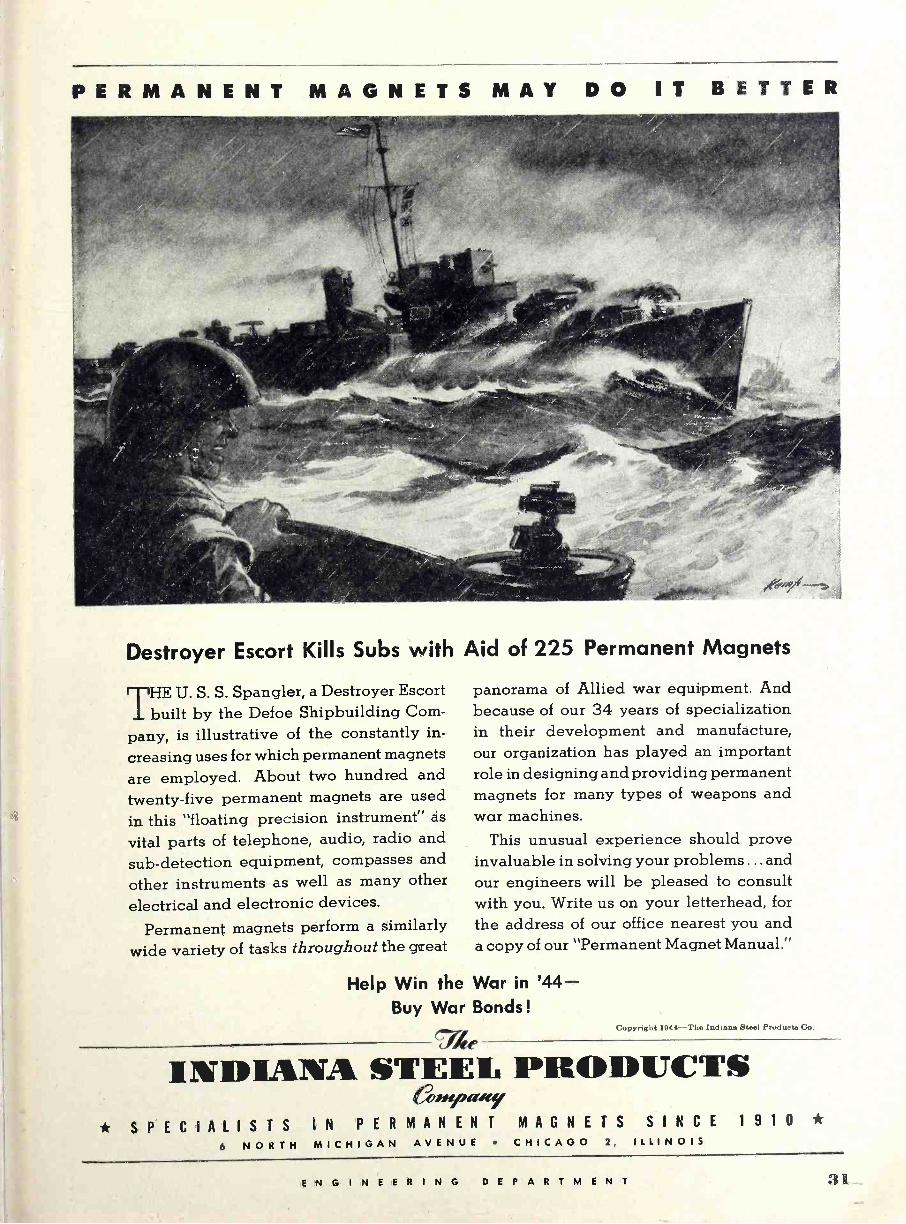
PERMANENT MAGNETS M A Y DO IT BETTER
Destroyer Escort Kills Subs with Aid of 225 Permanent Magnets
HE U. S. S. Spangler, a Destroyer Escort I built by the Defoe Shipbuilding Com-
pany, is illustrative of the constantly in-
creasing uses for which permanent magnets are employed. About two hundred and twenty-five permanent magnets are used in this "floating precision instrument" as
vital parts of telephone, audio, radio and
sub -detection equipment, compasses and
other instruments as well as many other
electrical and electronic devices.
Permanent magnets perform a similarly wide variety of tasks throughout the great
Help Win the Buy War
panorama of Allied war equipment. And because of our 34 years of specialization in their development and manufacture, our organization has played an important role in designing and providing permanent magnets for many types of weapons and war machines.
This unusual experience should prove invaluable in solving your problems ... and our engineers will be pleased to consult with you. Write us on your letterhead, for the address of our office nearest you and a copy of our "Permanent Magnet Manual."
War in '44- Bonds!
74e Copyright 1944-The Indiana ëteel Producto Co.
INDIANA STEEI, PRODUCTS 6ss>rpa*cy
* SPECIALISTS IN PERMANENT MAGNETS 6 NORTH MICHIGAN AVENUE CHICAGO 2,
SINCE 1 9 1 0 * ILLINOIS
ENGINEERING DEPARTMENT 31
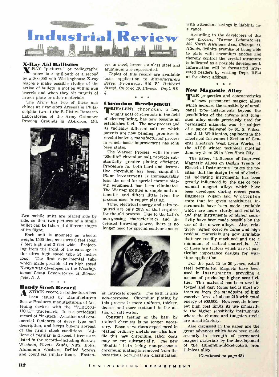
maamar- eriih Industrial Review X -Ray Aid Ballistics X-RAY "pictures," or radiographs,
taken in a millionth of a second by a 300,000 volt Westinghouse X-ray machine make possible studies of the action of bullets in motion within gun barrels and when they hit targets of armor plate or other materials.
The Army has two of these ma- chines at Frankford Arsenal in Phila- delphia, two at the Ballistics Research Laboratories of the Army Ordnance Proving Grounds in Aberdeen, Md.
Two mobile units are placed side by side, so that two pictures of a single bullet can be taken at different stages of its flight.
Each unit is mounted on wheels, weighs 1500 lbs., measures 8 feet long, 7 feet high and 3 feet wide. Project- ing from the front of the carriage is the ultra high speed tube 24 inches long. The first experimental tube which made possible ultra high speed X-rays was developed in the Westing- house Lamp Laboratories at Bloom- field, N. J.
* * *
Handy Stock Record ASTOCK record in folder form has
been issued by Manufacturers Screw Products, manufacturers of fas- tening devices with the "STRONG- HOLD" trademark. It is a periodical record of "in -stock" Aviation and com- mercial fasteners of every type and description, and. keeps buyers abreast of the firm's stock conditions. Mil- lions of regular and special items are listed in the record-including Screws, Washers, Rivets, Studs, Nuts, Bolts, Aluminum Washers, Drilled Screws and countless similar items. Fasten-
ers in steel, brass, stainless steel and aluminum are represented.
Copies of this record are available upon application to Manufacturers Screw Products, 216 W. Hubbard Street, Chicago 10, Illinois. Dept. RE - 4
* * *
Chromium Development TRIVALENT chromium, a long
sought goal of scientists in the field of electroplating, has now become an established fact. The new process and its radically different salt, on which patents are now pending, promises to revolutionize a manufacturing process in which basic improvement has long been static.
The Warner Process, with its new "Skalite" chromium salt, provides sub- stantially greater plating efficiency. Procedure for both hard and decora- tive chromium has been simplified. Plant investment is immeasurably less; the need for special chrome plat- ing equipment has been eliminated. The Warner method is simple and au- tomatic, and differs little from the process used in copper plating.
Time, electrical energy and salts re- quired are only 20% of that required for the old process. Due to the bath's non -gassing characteristics and in- creased throwing power, there is no longer need for special contour anodes
on intricate objects. The bath is also non -corrosive. Chromium plating by this process is more uniform, thicker, denser and more resistant to the ac- tion of salt water.
Constant testing of the bath by trained chemists is no longer neces- sary. Because workers experienced in plating ordinary metals can also han- dle this new chromium, labor costs may be cut substantially. The new "Skalite" bath being non-poisonous, chromium plating is removed from the hazardous occupation classification,
with attendant savings in liability in- surance.
According to the developers of this new process, Warner Laboratories, 360 North Michigan Ave., Chicago 11, Illinois, definite promise of being able to plate with chromium anodes and thereby control the crystal structure is indicated as a possible development. Information will be forwarded inter- ested readers by writing Dept. RE -4 at the above address.
*
New Magnetic Alloy E properties and characteristics
of new permanent magnet alloys which increase the sensitivity of small panel type instruments beyond the possibilities of the chrome and tung- sten alloy steels previously used for permanent magnets, was the subject of a paper delivered by M. S. Wilson and J. M. Whittenton, engineers in the Electrical Instrument Section of Gen- eral Electric's West Lynn Works, at the AIEE winter technical meeting January 24 to 28 in New York City.
The paper, "Influence of Improved Magnetic Alloys on Design Trends of Electrical Instruments," takes the po- sition that the design trend of electri- cal indicating instruments has been greatly influenced by the use of per- manent magnet alloys which have been developed during recent years. Engineers Wilson and Whittenton state that for given sensitivities, in- struments have been made available which are more sturdy and reliable, and that instruments of higher sensi- tivity have been made possible by the use of the newer alloys. Also, rela- tively higher coercive force and high residual materials are now available that are readily machined and use a minimum of critical materials. All of these are factors which are of par- ticular importance designs for war- time application.
For the past 15 to 20 years, cobalt steel permanent magnets have been used in instruments, providing a means of producing higher sensitivi- ties. This material has been used in forged and cast forms and is most at- tractive from the standpoint of high coercive force of about 210 with total energy of 900,000. However, its inher- ent high cost limits its use primarily to the higher sensitivity instruments where the chrome and tungsten steels are unsatisfactory.
Also discussed in the paper are the great advances which have been made recently in strength of permanent magnet materials by the development of the aluminum -nickel -cobalt iron (alnico) alloy.
(Continued on page 45)
32 ENGINEERING DEPARTMENT

One of the world's masterpieces in marble -"The Kiss", by the cel- ebrated French sculptor, Auguste Rodin (1840-1917), creator of the famed and familiar "The Thinker".
I achines can do almost anything. . . . But it 11. takes more than machines to create an elec-
tronic tube A. tube may be brilliantly engineered for electronic and mechanical advancements. It may contain the highest quality components. Yet it will be no better in performance than the skill and care of the hands t hat. assembled it. . . Each tube that. leaves the UNITED testing line is an industrial mas- terpiece. Into its manufacture has been wrought the perfect hand workmanship which is the counterpart. of its perfect design.
ELECTRONICS COMPANY New Jersey
Transmitting Tubes EXCLUSIVELY Since 1934
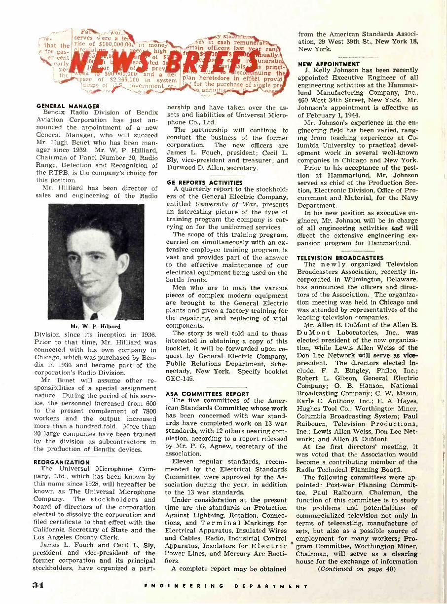
> that the for Bas- er cent
-early per
Fa,o serves were, a le; rise of $100,000,00í,
rculat'
of 1, k o $9 .0 ,000, nd a e
jordry_Base of $2.265,000 in system tdi'2e 01 ¡ government t-
in money cow high
of $ ted f prey
GENERAL MANAGER Bendix Radio Division of Bendix
Aviation Corporation has just an- nounced the appointment of a new General Manager, who will succeed Mr. Hugh Benet who has been man- ager since 1939. Mr. W. P. Hilliard, Chairman of Panel Number 10, Radio Range, Detection and Recognition of the RTPB, is the company's choice for this position.
Mr. Hilliard has been director of sales and engineering of the Radio
Mr. W. P. Hilliard Division since its inception in 1936. Prior to that time, Mr. Hilliard was connected with his own company in Chicago, which was purchased by Ben - dix in 1936 and became part of the corporation's Radio Division.
Mr. Benet will assume other re- sponsibilities of a special assignment nature. During the period of his serv- ice, the personnel increased from 600 to the present complement of 7800 workers and the output increased more than a hundred -fold. More than 20 large companies have been trained by the division as subcontractors in the production of Bendix devices.
REORGANIZATION The Universal Microphone Com-
pany, Ltd., which has been known by this name since 1928, will hereafter be known as The Universal Microphone Company. The stockholders and board of directors of the corporation elected to dissolve the corporation and filed certificate to that effect with the California Secretary of State and the Los Angeles County Clerk.
James L. Fouch and Cecil L. Sly, president and vice-president of the former corporation and its principal stockholders, have organized a part -
Cy Sta Js in cash remun rtain officers last y ran
uatly. r uneratio
als s princi- ulb 4lisco nuing th plan heretofore in effect provid i, for the purchase of si gle pr
annual
nership and have taken over the as- sets and liabilities of Universal Micro- phone Co., Ltd.
The partnership will continue to conduct the business of the former corporation. The new officers are James L. Fouch, president; Cecil L. Sly, vice-president and treasurer; and Durwood D. Allen, secretary.
GE REPORTS ACTIVITIES A quarterly report to the stockhold-
ers of the General Electric Company, entitled University of War, presents an interesting picture of the type of training program the company is car- rying on for the uniformed services.
The scope of this training program, carried on simultaneously with an ex- tensive employee training program, is vast and provides part of the answer to the effective maintenance of our electrical equipment being used on the battle fronts.
Men who are to man the various pieces of complex modern equipment are brought to the General Electric plants and given a factory training for the repairing, and replacing of vital components.
The story is well told and to those interested in obtaining a copy of this booklet, it will be forwarded upon re- quest by General Electric Company, Public Relations Department, Sche- nectady, New York. Specify booklet GEC -145.
ASA COMMITTEES REPORT The five committees of the Amer-
ican Standards Committee whose work has been concerned with war stand- ards have completed work on 13 war standards, with 12 others nearing com- pletion, according to a report released by Mr. P. G. Agnew, secretary of the association.
Eleven regular standards, recom- mended by the Electrical Standards Committee, were approved by the As- sociation during the year, in addition to the 13 war standards.
Under consideration at the present time are the standards on Protection Against Lightning, Rotation, Connec- tions, and Terminal Markings for Electrical Apparatus, Insulated Wires and Cables, Radio, Industrial Control Apparatus, Insulators for Electric Power Lines, and Mercury Arc Recti- fiers.
A complete report may be obtained
from the American Standards Associ- ation, 29 West 39th St., New York 18, New York.
NEW APPOINTMENT J. Kelly Johnson has been recently
appointed Executive Engineer of all engineering activities at the Hammar- lund Manufacturing Company, Inc., 460 West 34th Street, New York. Mr. Johnson's appointment is effective as of February 1, 1944.
Mr. Johnson's experience in the en- gineering field has been varied, rang- ing from teaching experience at Co- lumbia University to practical devel- opment work in several well-known companies in Chicago and New York.
Prior to his acceptance of the posi- tion at Hammarlund, Mr. Johnson served as chief of the Production Sec- tion, Electronic Division, Office of Pro- curement and Material, for the Navy Department.
In his new position as executive en- gineer, Mr. Johnson will be in charge of all engineering activities and will direct the extensive engineering ex- pansion program for Hammarlund.
TELEVISION BROADCASTERS The newly organized Television
Broadcasters Association, recently in- corporated in Wilmington, Delaware, has announced the officers and direc- tors of the Association. The organiza- tion meeting was held in Chicago and was attended by representatives of the leading television companies.
Mr. Allen B. DuMont of the Allen B. DuMont Laboratories, Inc., was elected president of the new organiza- tion, while Lewis Allen Weiss of the Don Lee Network will serve as vice- president. The directors elected in- clude, F. J. Bingley, Philco, Inc.; Robert L. Gibson, General Electric Company; O. B. Hanson, National Broadcasting Company; C. W. Mason, Earle C. Anthony, Inc.; E. A. Hayes, Hughes Tool Co.; Worthington Miner, Columbia Broadcasting System; Paul Raibourn, Television Productions, Inc.; Lewis Allen Weiss, Don Lee Net- work; and Allen B. DuMont.
At the first directors' meeting, it was voted that the Association would become a contributing member of the Radio Technical Planning Board.
The following committees were ap- pointed: Post-war Planning Commit- tee, Paul Raibourn, Chairman, the function of this committee is to study the problems and potentialities of commercialized television not only in terms of telecasting, manufacture of sets, but also as a possible source of employment for many workers; Pro- gram Committee, Worthington Miner, Chairman, will serve as a clearing house for the exchange of information
(Continued on page 40)
34 ENGINEERING DEPARTMENT
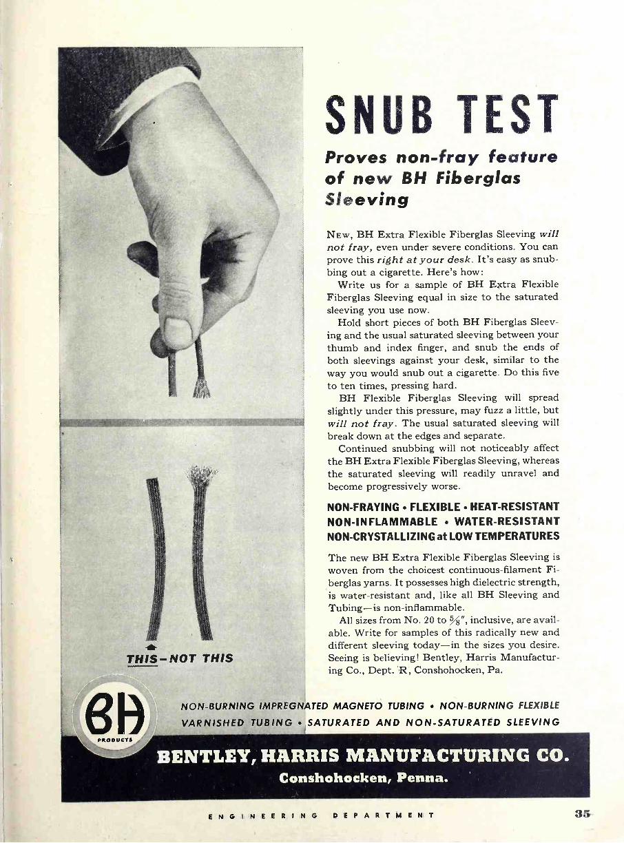
THIS-NOT THIS
PRODUCTS
SNUB TEST Proves non -fray feature of new 8H Fiberglas Sleeving
NEW, BH Extra Flexible Fiberglas Sleeving will not fray, even under severe conditions. You can prove this right at your desk. It's easy as snub- bing out a cigarette. Here's how:
Write us for a sample of BH Extra Flexible Fiberglas Sleeving equal in size to the saturated sleeving you use now.
Hold short pieces of both BH Fiberglas Sleev- ing and the usual saturated sleeving between your thumb and index finger, and snub the ends of both sleevings against your desk, similar to the way you would snub out a cigarette. Do this five
to ten times, pressing hard. BH Flexible Fiberglas Sleeving will spread
slightly under this pressure, may fuzz a little, but will not fray. The usual saturated sleeving will break down at the edges and separate.
Continued snubbing will not noticeably affect the BH Extra Flexible Fiberglas Sleeving, whereas the saturated sleeving will readily unravel and become progressively worse.
NON -FRAYING FLEXIBLE HEAT -RESISTANT
NON -INFLAMMABLE WATER-RESISTANT NON -CRYSTALLIZING at LOW TEMPERATURES
The new BH Extra Flexible Fiberglas Sleeving is
woven from the choicest continuous -filament Fi- berglas yarns. It possesses high dielectric strength, is water-resistant and, like all BH Sleeving and Tubing-is non -inflammable.
All sizes from No. 20 to %", inclusive, are avail- able. Write for samples of this radically new and different sleeving today-in the sizes you desire. Seeing is believing! Bentley, Harris Manufactur- ing Co., Dept. 'R, Conshohocken, Pa.
NON -BURNING IMPREGNATED MAGNETO TUBING NON -BURNING FLEXIBLE
VARNISHED TUBING SATURATED AND NON -SATURATED SLEEVING
BENTLEY, HARRIS MANUFACTURING CO. Conshohocken, Penna.
ENGINEERING DEPARTMENT 35
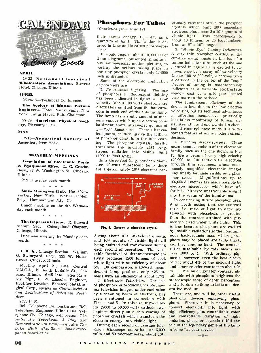
19-22-National Electrical Wholesalers Association, Stevens Hotel, Chicago, Illinois.
APRIL 25-26-27-Technical Conference. The Society of Motion Picture
Engineers, Hotel Pennsylvania, New York. Julius Haber, Pub., Chairman.
27-29-American Physical Soci- ety, Pittsburgh, Pa.
MAY
12-13-Acoustical Society of America, New York.
MONTHLY MEETINGS Association of Electronic Parts
& Equipment Mirs. L. G. Groebe, Secy., 77 W. Washington St., Chicago, Illinois.
2nd Thursday each month. * * * *
Sales Managers Club. Hotel New Yorker, New York. Walter Jablon, Secy., Hammarlund Mfg. Co.
Lunch meeting on the 4th Wednes- day each month.
* * * *
The Representatives. R. Edward Stemm, Secy. Chicagoland Chapter, Chicago, Illinois.
Luncheon meeting 1st Monday each month.
I. R. E., Chicago Section. William O. Swineyard, Secy., 325 W. Huron Street, Chicago, Illinois.
Meeting April 21, 1944, Central Y.M.C.A., 19 South LaSalle St., Chi- cago, Illinois. 6:45 P.M., Glen Ram- sey, Mgr., E. W. Lincoln, Engineer, Rectifier Division, Fansteel Metallur- gical Corp., speaks on Characteristics and Applications of Selenium Recti- fiers.
7:55 P. M. Bell Telephone Demonstrators, Bell
Telephone Engineer, Illinois Bell Tel- ephone Co., Chicago, will present The Automatic Telephone, A Play and Demonstration of Equipment, also The Lake Bluff Ship -Shore Radio -Tele- phone Installation.
Phosphors For Tubes (Continued from page 12)
their excess energy, B1 - A+, as a quantum of light. This action is de- layed in time and is called phosphores- cence.
It would require about 10,000,000 of these diagrams, presented simultane- ous 3 -dimensional motion pictures, to portray the actions taking place in one tiny phosphor crystal only 1/4000 inch in diameter.
Some of the electronic application of phosphors are :
1. Fluorescent Lighting. The use of phosphors in fluorescent lighting has been indicated in figure 4. Low velocity (about 100 volt) electrons are alternately emitted from the hot cath- odes in each end of the tubular lamp. The lamp has a slight amount of mer- cury vapour which upon electron bom- bardment emits ultraviolet quanta of A = 2537 Angstroms. These ultravio- let quanta, in turn, strike the billions of phosphor crystals in the tube coat- ing. The phosphor crystals, finally, transform the invisible 2537 Ang- stroms radiation into visible light (4000 to 7000 Ang.).
In a three-foot long, one -inch diam- eter, 40 -watt fluorescent lamp there are approximately 1018 electrons pro -
8,
EEx
T,
T2
EXCITING ENERGY
Fig. 8. Energy in phosphor crystal.
ducing about 10t8 ultraviolet quanta, and 1018 quanta of visible light; all being emitted and transformed during each second of operation. This veri- table "beehive" of ultramicroscopic ac- tivity produces 1200 lumens of cool, white light with an efficiency of about 5%. By comparison, a 40 -watt incan- descent lamp produces only 425 lu- mens with an efficiency of about 1.7%.
2. Electronic Television. The use of phosphors in producing visible mov- ing television images, under excitation by a scanning beam of electrons, has been mentioned in connection with Figs. 1 and 5. In this use, high -veloc- ity (5000 to 50,000 -volt) cathode rays impinge directly on a thin coating of phosphor crystals which transform the electron energy into visible light.
During each second of average tele- vision Kinescope operation, at 6,000 volts and 50 microamperes, about 1014
primary electrons strike the pnosphor crystals which emit 1014 secondary electrons plus about 3 x 10¹⁸ quanta of visible light. This corresponds to about 10 lumens, or 20 foot -lamberts from an 8" x 10" image.
3. "Magic Eye" Tuning Indicators. A very thin phosphor coating in the cup -like metal anode in the top of a tuning indicator tube, such as the one pictured in figure 13, is excited to lu- minescence by a spray of low -velocity (about 100 to 300 -volt) electrons from a cathode in the center of the "cup." Degree of tuning is instantaneously indicated as a variable electrostatic shadow cast by a grid post located proximate to the cathode.
The luminescent efficiency of this device is low, due to the low electron velocities, but its technical advantages in affording inexpensive, practically inertialess monitoring of tuning, sig- nal strength, and end points (in chem- ical titrimetry) have made it a wide- spread feature of many modern circuit designs.
4. Electron Microscopes. These more recent members of the electronic family, such as the one shown in Fig. 15, fire a beam of very high -velocity (20,000 to 200,000 -volt) electrons through thin specimens whose enor- mously magnified electronic images may finally be made visible by a phos- phor screen. Magnifications up to 100,000 diameters are made possible by electron microscopes which have af- forded a hitherto unattainable insight into the realm of the infinitesimal.
In considering future phosphor uses, it is worth noting that the contrast ratio, i.e. ratio of light to dark, at- tainable with phosphors is greater than the contrast attained with pig- ments viewed under white light. This is true because phosphors are excited by invisible radiations so the non -lumi- nous backgrounds upon which phos- phors may be placed are truly black, i.e., they emit no light. The contrast ratios attainable by this means are over 1000 to 1. With ordinary pig- ments, however, even the best blacks reflect about 4% of the incident light and hence restrict contrast to about 25 to 1. The much greater contrast ob- tainable with phosphors heightens the stereoscopic sense of depth perception and affords a striking artistic and dec- orative medium.
There are, and will be, other useful electronic devices employing phos- phors. Wherever it is necessary to convert electricity into light, with high efficiency plus controllable color and controllable duration of light emission, phosphor crystals fulfill the role of the legendary genie of the lamp in being "at your service."
36 ENGINEERING DEPARTMENT

Yu. Mvdd 610-c8
MEG-O-METER
ADDED FEATURE
THE MODEL 610-B IS IDEAL FOR EITHER
BENCH OR FIELD WORK. OPERATES ON
2 SELF - CONTAINED BATTERIES. NO EX-
TERNAL SOURCE OF CURRENT IS RE-
QUIRED.
a, Welt, 68.aticy_-o
INSULATION T E S T E R!!
Instantaneously measures the exact leakage of all insulation
from zero up to
200 MEGOHMS At a Test Potential of
500 VOLTS D. C. Supplied by built-in battery and vibrator power supply.
3 RANGES: 0 - 20,000 OHMS. 0 -2 MEGOHMS. 0-200 MEGOHMS.
The MODEL 610-B has been designed to function with a high degree of resistance measuring instrument and as an insulation
tester. In addition to the 0 to 200 Megohm Range which is used for insulation testing, two additional
lower resistance ranges are provided. The two lower Resistance Ranges are 0 to 20,000 Ohms and 0 to 2
Megohms. Thus the MODEL 610-B may be used to accurately measure all resistances from 0 to 200
Megohms.
f
: accuracy both as a
NO HAND CRANKING- The 500 VOLT POTENTIAL is made instantly available by
simply throwing a front panel toggle switch.
*DIRECT READING- All calibrations printed in large easy -to -read type enabling exact de-
termination of leakages from 0 to 200 Megohms. In addition, tine
Megohm scale is also sub -divided into BAD (0 to I Megohm) DOUBTFUL (I to 3 Megohms) GOOD (3 to
200 Megohms) sections. The BAD Section which indicates the danger point is printed in red.
*The instrument is housed in a heavy-duty Oak portable cabinet.
*Meter movement-a 41/2" 0 to 200 Microampere sensitive meter guarantees extremely accurate read-
ings on all ranges.
Model 610-B comes housed in a beautiful, hand -rubbed Oak cabinet complete
with cover, self-contained batteries, test leads and instructions. Size 91/2" x 81/2" x 6". Shipping weight, 16 pounds. Price
giflpOJififfl.L We also make the Model 610-E Meg -O -Meter which operates on 110
Volt 60 Cycle A.C. The Model 610-E is especially recommended for
production testing where product must meet specified insulation requirements. Model 6 10-E
provides exactly same services as the Model 610-B except that it operates on 1 10 Voli
A.C. current instead of batteries. Price of Model 610-E complete is
SUPERIOR INSTRUMENTS CO., Dept. R. N., 227 Fulton St., New York 7, N.Y.
ENGINEERING DEPARTMENT 37

New Products (Continued from page 30)
ation, or rate of change of velocity, Is controlled automatically by a device which changes the frequency from 10 cycles per second to 55 cycles per sec- ond and back to 10 cps. continuously and uniformly. The complete cycle requires one minute. Frequencies are recorded on a sensitive electric tach- ometer.
The unit is powered by Ya hp., 110 volt, 60 cycles, a.c. split phase motor. The tester simulated vibration fatigue which may be encountered under ac- tual operating conditions.
This testing machine is fully de- scribed in Bulletin 210, Dept. RE -4, All American Tool and Mfg. Com- pany, 1014 Fullerton Avenue, Chicago, 14, Illinois.
SYNCHRONOUS MOTORS The Leich Synchronous Motor is de-
signed to meet the demand of manu- facturers of control, timing, and re- cording devices who require a com- pact, sturdy and accurate synchron- ous motor.
The rotating element of the motor operates at a fixed speed which is de- termined by the frequency of the al- ternating current energizing the mo- tor. With most power systems oper- ating at a fixed frequency, it is possi- ble to operate dependent on exact tim- ing for proper functioning by means of these motors.
Standard output shaft speeds of 1-4- 15 and 60 r.p.m. can be furnished. By means of external movements, slow speeds of one revolution per hour, per twelve hours and per twenty-four hours can be obtained.
Special motors, designed to fill cer- tain engineering requirements, may be furnished if ordered in sufficient numbers to make the necessary tool- ing worthwhile.
For further information, inquiries and engineering problems, inquiries should be addressed to Leich Electric Company, Genoa, Illinois, Dept. RE -4.
THYRATRON CONTROL A new thyratron welding control for
providing precise control of low -ca- pacity spot welders has been an- nounced by the Industrial Control Di- vision of the General Electric Com- pany. Coupled with a suitable weld- ing transformer, this control can be used with either welding tongs or a
small bench welder, and is particu- larly suitable for the spot-welding of vacuum tube parts.
Other applications for which the control, in combination with the proper welding transformer, is desir- able include the welding of solid or stranded wires to terminals of copper, brass, bronze, steel, or ferrous alloys; joining two tinned -copper, steel, or al- loy wires; and spot-welding thin pieces of various alloys.
Suitable for operation on either 230 or 460 -volt, 60 -cycle power supply, the new control is an adjustable, synchron- ous -precision, electronic type in which only three thyratron tubes perform all the functions. Two Type FG -172 tubes control the primary current of the welding transformer, and a single Type FG -97 tube controls the firing time. Since the tubes have the same current rating on either voltage, the transformer used on a 460 -volt sup- ply can be twice as large as that used on a 230 -volt source, which will ap- proximately double the secondary cur- rent. The control is rated 53 amperes rms (primary current of the welding transformer) on a duty cycle not ex- ceeding ten per cent.
The new control is mounted in a compact, dead -front metal enclosure designed to permit the control to be attached either to the top of the as- sembly bench or underneath, by a sim- ple reassembly of parts. A single cali- brated time adjustment on the front of the panel provides either one-half cycle or any number of complete cy- cles from one to ten. The removable cover of the enclosure allows quick In- spection and complete accessibility of all component parts.
Additional information is contained in Bulletin GEA -4175, Dept. RE -4, available from the General Electric Company, Schenectady, N. Y.
INSPECTION UNIT A complete inspection department,
which may be brought to the point of work, is the product of the Continen- tal Machines, Inc. Known as the Do - ALL Mobile Inspection unit, this labo- ratory on wheels contains all of the necessary instruments and gauges usually found in a plant inspection de- partment.
Regular testing, or periodic sam-
pling may be accomplished on this one instrument. The unit occupies an area of approximately 24" x 42" and can be brought to the machines which are producing the to -be -tested sam- ples. The unit is all steel construc- tion which assures sturdiness. Rubber tired, heavy duty caster wheels permit easy movement, while during the op- eration of the unit, the wheels can be locked for steadiness.
Every convenience is provided for the inspector to facilitate easy testing. A plug -in -box at the back of the unit permits an easily accessible outlet for attaching the fifty foot extension cord and automatic take-up reel.
A desk drawer and chair is fur- nished to permit the inspector to re- cord the information and results that he obtains from his tests.
Many other features of this unit will be described by Continental Ma- chines, Inc., 1301 Washington Boule- vard, South, Minneapolis, Minnesota, upon request to Dept. RE -4.
CAPACITY METER An interelectrode capacity meter,
with a range of from .001 to 100 mmfds. has been announced by the Technical Apparatus Company of Bos- ton.
Simplicity of operation permits un- skilled personnel to use this meter as easily as an engineer, as readings are taken direct from the large dial and read in micro-microfarads. The tube to be measured is plugged into a wholly shielded measuring circuit in- corporated in the instrument.
The connector base accepts adapters for tubes up to 8 -pin and provides for connection of coaxial cablcs to any pair of elements whose capacity is to be measured. The "universal" shield furnished with the instrument accom- modates tubes up to 2%" in diam- eter and 4%" high. Standard RMA shields, as specified for various tube types may also be used. Special shields for unusual tube types may be furnished.
Special adapters for measurements other than for vacuum tubes are available.
The flexibility of this instru- ment coupled with the advantage of simplicity of operation makes this
(Continued on page 43)
38 ENGINEERING DEPARTMENT
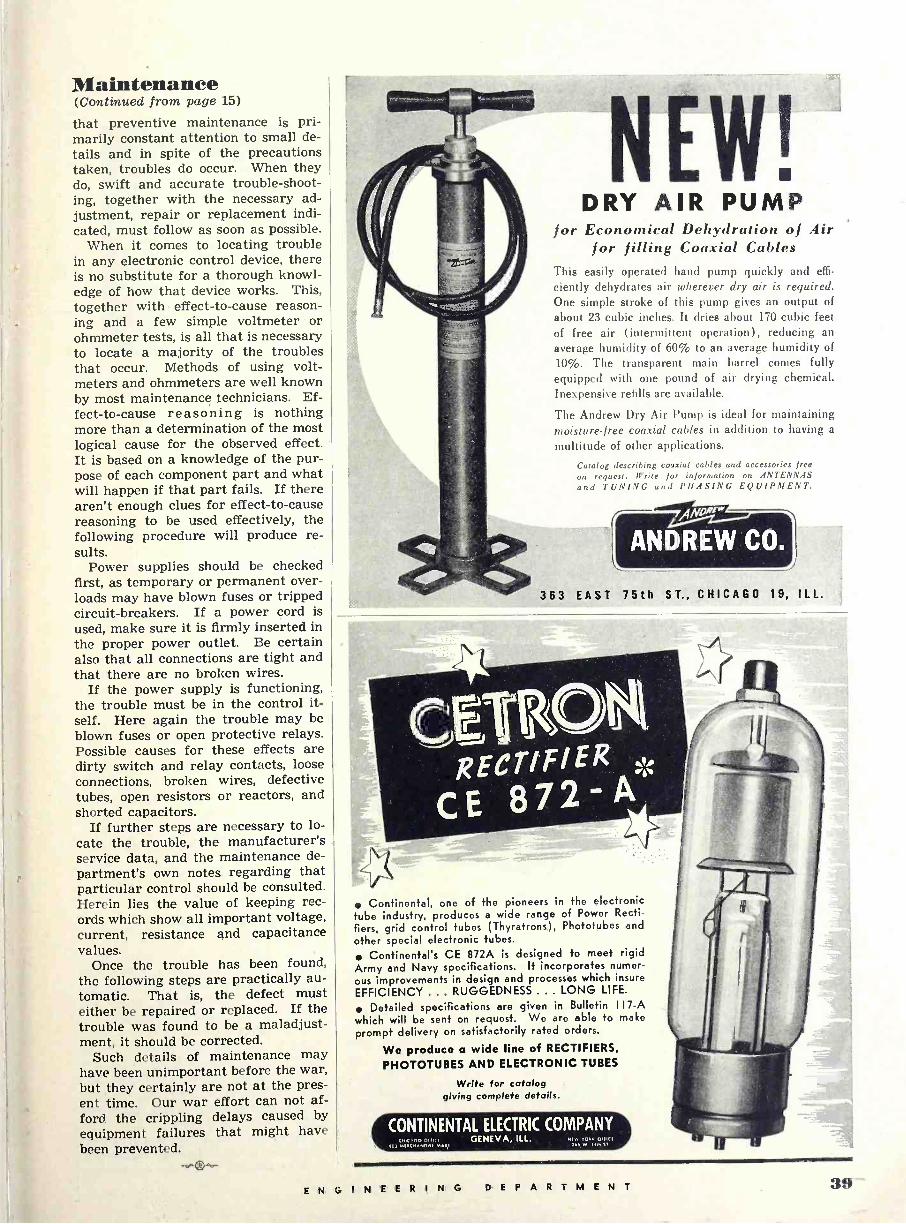
Maintenance (Continued from page 15)
that preventive maintenance is pri- marily constant attention to small de- tails and in spite of the precautions taken, troubles do occur. When they do, swift and accurate trouble -shoot- ing, together with the necessary ad- justment, repair or replacement indi- cated, must follow as soon as possible.
When it comes to locating trouble in any electronic control device, there is no substitute for a thorough knowl- edge of how that device works. This, together with ' effect -to -cause reason- ing and a few simple voltmeter or ohmmeter tests, is all that is necessary to locate a majority of the troubles that occur. Methods of using volt- meters and ohmmeters are well known by most maintenance technicians. Ef- fect -to -cause reasoning is nothing more than a determination of the most logical cause for the observed effect. It is based on a knowledge of the pur- pose of each component part and what will happen if that part fails. If there aren't enough clues for effect -to -cause reasoning to be used effectively, the following procedure will produce re- sults.
Power supplies should be checked first, as temporary or permanent over- loads may have blown fuses or tripped circuit -breakers. If a power cord is used, make sure it is firmly inserted in the proper power outlet. Be certain also that all connections are tight and that there are no broken wires.
If the power supply is functioning, the trouble must be in the control it- self. Here again the trouble may be blown fuses or open protective relays. Possible causes for these effects are dirty switch and relay contacts, loose connections, broken wires, defective tubes, open resistors or reactors, and shorted capacitors.
If further steps are necessary to lo- cate the trouble, the manufacturer's service data, and the maintenance de- partment's own notes regarding that particular control should be consulted. Herein lies the value of keeping rec- ords which show all important voltage, current, resistance and capacitance values.
Once the trouble has been found, the following steps are practically au- tomatic. That is, the defect must either be repaired or replaced. If the trouble was found to be a maladjust- ment, it should be corrected.
Such details of maintenance may have been unimportant before the war, but they certainly are not at the pres- ent time. Our war effort can not af- ford the crippling delays caused by equipment failures that might have been prevented.
DRY AIR PUMP for Economical Dehydration of Air
for filling Coaxial Cables This easily operated hand pump quickly and effi-
ciently dehydrates air wherever dry air is required. One simple stroke of this pump gives an output of about 23 cubic inches. It dries about 170 cubic feet of free air (intermittent operation), reducing an
average humidity of 60% to an average humidity of 10%. The transparent main barrel comes fully equipped with one pound of air drying chemical. Inexpensive refills are available.
The Andrew Dry Air Pump is ideal for maintaining moisture -free coaxial cables in addition to having a
multitude of other applications.
Catalog describing coaxial cables and accessories free on request. JI ' re for information on ANTENNAS and TUN!\ (, and PHASING EQUIPMENT.
363 EAST 75th ST., CHICAGO 19, ILL.
Continental, one of the pioneers in the electronic tube industry, produces a wide range of Power Recti-
fiers, grid control tubes (Thyratrons), Phototubes and
other special electronic tubes.
Continental's CE 872A is designed to meet rigid Army and Navy specifications. It incorporates numer-
ous improvements in design and processes which insure
EFFICIENCY ... RUGGEDNESS . .. LONG LIFE.
Detailed specifications are given in Bulletin 17 -A
which will be sent on request. We are able to make
prompt delivery on satisfactorily rated orders.
We produce a wide line of RECTIFIERS,
PHOTOTUBES AND ELECTRONIC TUBES
Write for catalog giving complete details.
CONTINENTAL ELECTRIC COMPANY wuco o n1.1.. n GENEVA, ILL. + +o o in
101 IIIMl.NOI11 MARI ]et W N,F fl
ENGINEERING DEP AR TMENT :i9
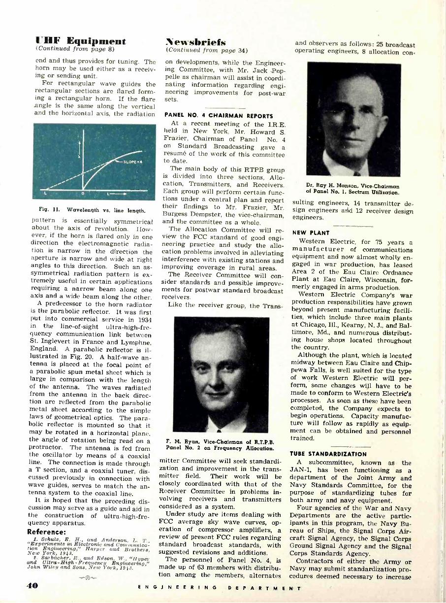
UHF Equipment (Continued from page 8)
end and thus provides for tuning. The horn may be used either as a receiv- ing or sending unit.
For rectangular wave guides the rectangular sections are flared form- ing a rectangular horn. If the flare .angle is the same along the vertical and the horizontal axis, the radiation
Fig. ll. Wavelength vs. line length.
pattern is essentially symmetrical about the axis of revolution. How- ever, if the horn is flared only in one direction the electromagnetic radia- tion is narrow in the direction the aperture is narrow and wide at right angles to this direction. Such an as - symmetrical radiation pattern is ex- tremely useful in certain applications requiring a narrow beam along one axis and a wide beam along the other.
A predecessor to the horn radiator is the parabolic reflector. It was first put into commercial service in 1934 in the line -of -sight ultra -high -fre- quency communication link between St. Inglevert in France and Lymphne, England. A parabolic reflector is il- lustrated in Fig. 20. A half -wave an- tenna is placed at the focal point of a parabolic spun metal sheet which is large in comparison with the length of the antenna. The waves radiated from the antenna in the back direc- tion are reflected from the parabolic metal sheet according to the simple laws of geometrical optics. The para- bolic reflector is mounted so that it may be rotated in a horizontal plane, the angle of rotation being read on a protractor. The antenna is fed from the oscillator by means of a coaxial line. The connection is made through a T section, and a coaxial tuner, dis- cussed previously in connection with wave guides, serves to match the an- tenna system to the coaxial line.
It is hoped that the preceding dis- cussion may serve as a guide and aid in the construction of ultra -high -fre- quency apparatus. Reference:
1. Schulz, E. H., and Anderson, L. T., "Experiments im Electronic and Communica- tion Engineering," Harper and Brothers, New York, 1943. L. Saibacher, R., and Edson., W., "Hyper
and Ultra -High -Frequency Engineering," John Wiley and Sons, New York, 1943.
N ewsbriefs (Continued from page 34)
on developments, while the Engineer- ing Committee, with Mr. Jack Pop- pelle as chairman will assist in coordi- nating information regarding engi- neering improvements for post-war sets.
PANEL NO. 4 CHAIRMAN REPORTS At a recent meeting of the I.R.E.
held in New York, Mr. Howard S. Frazier, Chairman of Panel No. 4 on Standard Broadcasting gave a resumé of the work of this committee to date.
The main body of this RTPB group is divided into three sections, Allo- cation, Transmitters, and Receivers. Each group will perform certain func- tions under a central plan and report their findings to Mr. Frazier, Mr. Burgess Dempster, the vice-chairman, and the committee as a whole.
The Allocation Committee will re- view the FCC standard of good engi- neering practice and study the allo- cation problems involved in alleviating interference with existing stations and improving coverage in rural areas.
The Receiver Committee will con- sider standards and possible improve- ments for postwar standard broadcast receivers.
Like the receiver group, the Trans -
F. M. Ryan, Vice -Chairman of R.T.P.B. Panel No. 2 on Frequency Allocation.
mitter Committee will seek standardi- zation and improvement in the trans- mitter field. Their work will be closely coordinated with that of the Receiver Committee in problems in- volving receivers and transmitters considered as a system.
Under study are items dealing with FCC average sky wave curves, op- eration of compressor amplifiers, a review of present FCC rules regarding standard broadcast standards, with suggested revisions and additions.
The personnel of Panel No. 4, is made up of 63 members with distribu- tion among the members, alternates
and observers as follows: 25 broadcast operating engineers, 8 allocation con -
Dr. Ray H. Manson, Vice -Chairman of Panel No. 1, Sectrum Utilization.
suiting engineers, 14 transmitter de- sign engineers arid 12 receiver design engineers.
NEW PLANT Western Electric, for 75 years a
manufacturer of communications equipment and now almost wholly en- gaged in war production, has leased Area 2 of the Eau Claire Ordnance Plant at Eau Claire, Wisconsin, for- merly engaged in arms production.
Western Electric Company's war production responsibilities have grown beyond present manufacturing facili- ties, which include three main plants at Chicago, Ill., Kearny, N. J., and Bal- timore, Md., and numerous distribut- ing house shops located throughout the country.
Although the plant, which is located midway between Eau Claire and Chip- pewa Falls, is well suited for the type of work Western Electric will per- form, some changes will have to be made to conform to Western Electric's processes. As soon as these have been completed, the Company expects to begin operations. Capacity manufac- ture will follow as rapidly as equip- ment can be obtained and personnel trained.
TUBE STANDARDIZATION A subcommittee, known as the
JAN -1, has been functioning as a department of the Joint Army and Navy Standards Committee, for the purpose of standardizing tubes for both army and navy equipment.
Four agencies of the War and Navy Departments are the active partic- ipants in this program, the Navy Bu- reau of Ships, the Signal Corps Air- craft Signal Agency, the Signal Corps Ground Signal Agency and the Signal Corps Standards Agency.
Contractors of either the Army or Navy may submit standardization pro- cedures deemed necessary to increase
40 ENG INEERING DEPARTM ENT
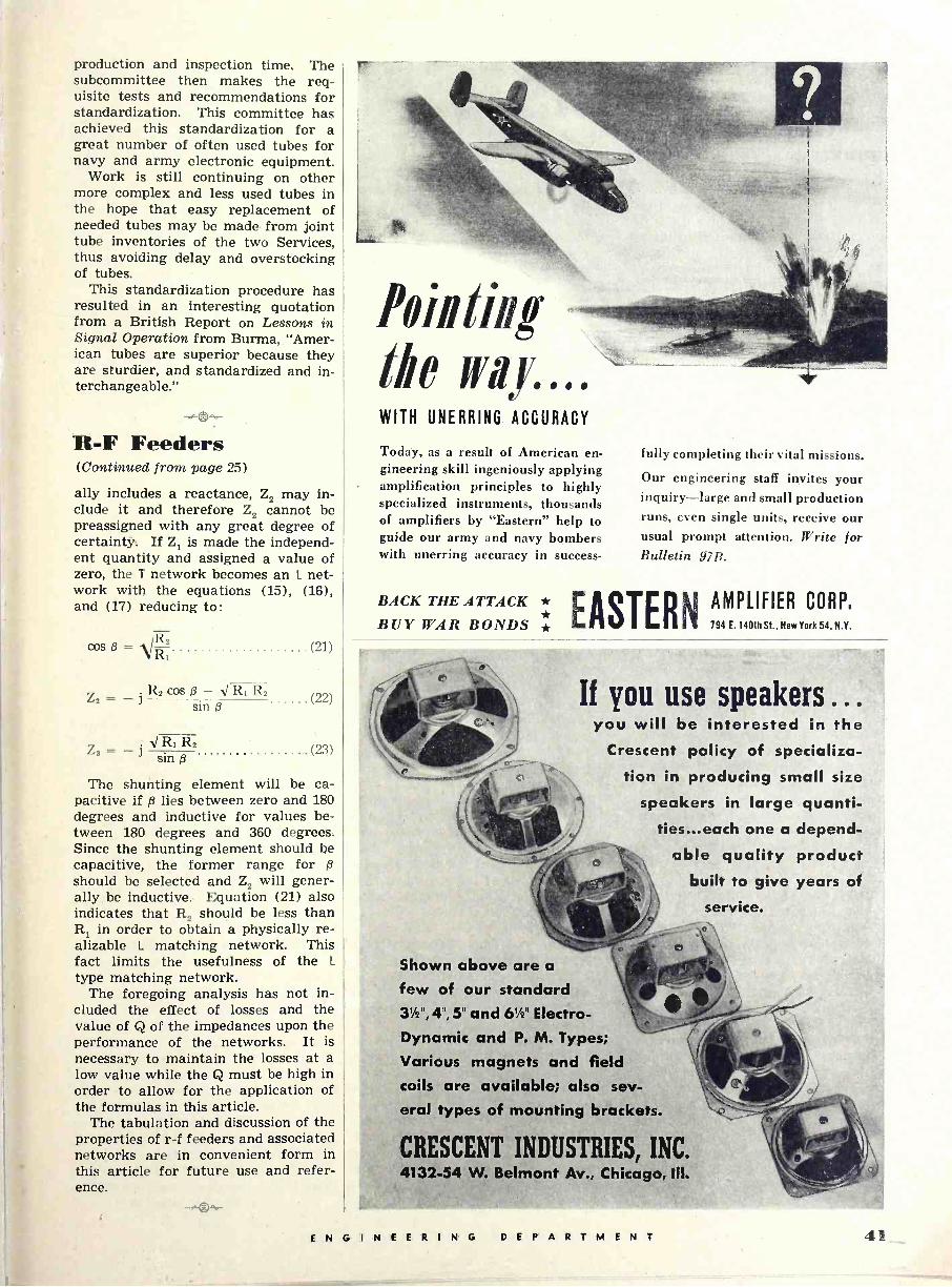
production and inspection time. The subcommittee then makes the req- uisite tests and recommendations for standardization. This committee has achieved this standardization for a great number of often used tubes for navy and army electronic equipment.
Work is still continuing on other more complex and less used tubes in the hope that easy replacement of needed tubes may be made from joint tube inventories of the two Services, thus avoiding delay and overstocking of tubes.
This standardization procedure has resulted in an interesting quotation from a British Report on Lessons in Signal Operation from Burma, "Amer- ican tubes are superior because they are sturdier, and standardized and in- terchangeable."
IL -F Feeders (Continued from page 25)
ally includes a reactance, Z2 may in- clude it and therefore Z2 cannot be preassigned with any great degree of certainty, If Z1 is made the independ- ent quantity and assigned a value of zero, the T network becomes an L net- work with the equations (15), (16), and (17) reducing to:
cos ß = V R, (21)
(22) Z2 R2 cos ß -1V RI R2
sin ß
Z8 = - j 'V R2 (23)
sin ß
The shunting element will be ca- pacitive if ß lies between zero and 180 degrees and inductive for values be- tween 180 degrees and 360 degrees. Since the shunting element should be capacitive, the former range for ß should be selected and Z2 will gener- ally, be inductive. Equation (21) also indicates that R2 should be less than R1 in order to obtain a physically re- alizable L matching network. This fact limits the usefulness of the L
type matching network. The foregoing analysis has not in-
cluded the effect of losses and the value of Q of the impedances upon the performance of the networks. It is necessary to maintain the losses at a low value while the Q must be high in order to allow for the application of the formulas in this article.
The tabulation and discussion of the properties of r -f feeders and associated networks are in convenient form in this article for future use and refer- ence.
WITH UNERRING ACCURACY
Today, as a result of American en- gineering skill ingeniously applying amplification principles to highly specialized instruments, thousands of amplifiers by "Eastern" help to guide our army and navy bombers with unerring accuracy in success -
BACK THE ATTACK * BUY WAR BONDS *
fully completing their vital missions.
Our engineering staff invites your inquiry-large and small production runs, even single units, receive our usual prompt attention. Write for Bulletin 97R.
EASTERN
AMPLIFIER CORP, 794 E.140th St., New York 54, N.Y.
If you use speakers ... you will be interested in the
Crescent policy of specializa- tion in producing small size
speakers in large quanti- ties...each one a depend-
able quality product built to give years of
service.
Shown above are a
few of our standard 31/2", 4", 5" and 61/2" Electro - Dynamic and P. M. Types;
Various magnets and field coils are available; also sev- eral types of mounting brackets.
CRESCENT INDUSTRIES, INC. 4132-54 W. Belmont Av., Chicago, III.
ENGINEERING DEPARTMENT 11
"HEARING," by S. S. Stevens and H. Davis. Published by John Wiley and Sons, Inc., 440 Fourth Avenue, New York, N. Y. 489 pages. Price $4.50. This book is an authoritative ac-
count of the acoustical properties of the human ear, and includes experi- mental results relating to loudness, pitch and frequency sensitivity. These topics are analyzed in a manner which enables the results to be applied to architectural as well as electro acous- tics. This treatment of the subject will be of particular interest to the acoustical engineer regardless of his specialized branch of science.
Such interesting topics as auditory masking are studied in detail with the aid of empirical charts and graphs which are of value to design engineers who are confronted with the problems of eliminating undesirable sounds and noises in industrial applications.
Not since Helmholtz wrote his trea- tise on human hearing in 1863 has such a comprehensive work on the subject of human hearing in terms of electrical phenomena appeared. Since that date great vistas of new tech- nical knowledge have opened and the necessity for such a work as this one by Drs. Stevens and Davis was cre- ated.
Formulas for auditory phenomena in electrical terms make up an inter- esting section of the appendices. Ta- bles and charts shówing ratios in decibels as well as glossary of terms further enhances the value of this text. A most complete bibliography covering domestic as well as foreign writings on the subject of human hear- ing is included for further study on the subject.
"ULTRASONICS," by L. Bergman and translated by H. S. Hatfield. Published by John Wiley and Sons, Inc., 440 Fourth Avenue, New York, N.Y. 264 pages. Price $4.00. Ultrasonics applied to submarine
detection was one of the most impor- tant applications for this science in World War I. Similar applications are being made in the present con- flict, however by referring to an arti- cle on the subject of Ultrasonics in the February issue of this magazine, new and varied uses may be visualized, all of which are not related directly to pursuance of war.
Since this subject is again receiving considerable attention, it is well to be aware of the textual material that exists on the subject.
* * *
This book is divided into five main topics, each of which occupies one chapter in the book. The first part deals with the available methods for generating ultrasonic energy. These methods include mechanical, thermal, magnetostriction and piezoelectric generators. The piezoelectric method of generating ultrasonic energy is the most effective and convenient method developed thus far. The construction of typical crystal generators and their associated circuits are discussed in chapter 1.
The second part of this book pre- sents the methods of detecting and measuring ultrasonic waves by me- chanical, thermal, electrical and op- tical means. The electrical and op- tical methods, which are extremely sensitive, are very well explained with complete illustrative material. The placing of experimental methods, with the results obtained, in the primary position, with a discussion of the the- ory last, is a wise choice as the easy understanding of the matter assem- bled in this manner is facilitated.
The third and fourth chapters in- clude various experimental methods of measuring the velocity of ultrasonic energy in liquids, gases and solids.
The fifth and final chapter is de- voted entirely to the applications of ultrasonics. Various uses ranging from applications in television to chemical, thermal and biological ef- fects are analyzed authoritatively and clearly with the aid of diagrams and photographs.
This book includes a comprehen- sive bibliography of over 450 refer- ences to articles dealing with the sub- ject of ultrasonics. To persons inter- ested in this subject this book offers a basic treatment of the subject as well as a complete and valuable bibli- ography for further study.
"TABLES OF FUNCTIONS WITH FORMULAE AND CURVES," by E. Jahnke and F. Emde. Published, 1943, by Dover Publication, 31 East 27th Street, New York. 303 pages. Price $3.50. This volume contains a collection
of tables, formulas and curves of a great many mathematical functions justifying its reputation as the world famous computing aid for workers in mathematics, physics and engineering. An outstanding feature of this book is the manner in which the graphs are drawn, a great many of which are plotted as contour surfaces represent- ing the functions in three dimensions.
This volume includes the original German text on the same page with the English translation.
Of the various mathematical func- tions tabulated, some are of particular interest to the radio engineer. A few of these important functions are the sine -integral, cosine -integral, expo- nential -integral, elliptic -integral and Bessel functions with real and com- plex arguments. These functions find application in the analysis and design of filters, thermionic tubes, high -fre- quency resistances, wave guides and FM side bands.
This book was first published in 1933 and a new edition appeared in 1938 with improvements and omis- sions of various parts of the 1933 edi- tion. The 1943 edition is a reprint of the 1938 edition with the omitted por- tions from the 1933 edition included.
"PRESENT SAVINGS AND POST- WAR MARKETS" by Sumner H. Slichter. Published by McGraw-Hill Company, New York. 73 pages. Price $1.00. In this book Prof. Slichter has pre-
sented a very real and urgent problem now facing the United States, that of inflation and the subsequent postwar depression.
Mr. Slichter is presenting facts, not opinions, regarding our present mone- tary structure. He has prepared a thoughtful analysis of the crisis we may have to face if the public indulges in a buying spree comparable to the one which plunged the country into the depression years.
Industry is accumulating vast liquid assets in the form of cash and bonds and it is evident that care in expending such vast sums must be taken to avoid the over expansion which seems likely in view of the competition which will devélop for the new and rich consumer markets which will open up after the war.
This book deserves a place on the reading shelf of every thoughtful American who can remember October 1929.
"RADIO RECEIVER DESIGN," by Dr. K. R. Sturley. Published by John Wiley and Sons, Inc., New York. 421 pages. Price $4.50. Dr. Sturley has made a real contri-
bution to the art of receiver design in this book. In the past it has been nec- essary to consult many texts in order to secure a lucid explanation of the components of a radio receiver. But here between two covers, Dr. Sturley has gathered a wealth of material on the subject, which he presents in an easily understandable form.
Beginning with the aerial, the au- thor traces the signal through the re -
(Continued on page 46)
42 ENGINEERING DEPARTMENT

New Products (Continued from page 38)
capacity meter a worthwhile addition to the usual testing and inspection equipment to be found in most facto- ries and laboratories. Large quantity testing may be handled quickly and
efficiently when this instrument is made part of the standard inspection equipment.
Interested persons should address inquiries to Dept. RE -4, Technical Apparatus Company, 1171 Tremont Street, Boston 20, Massachusetts.
HAND GENERATORS One of the sturdy components being
built into the Signal Corps' famous field telephones, the EE -8 and EE -8A, is a new lightweight generator made by Kellogg Switchboard and Supply Company of Chicago, Illinois.
Known as the GN -38-B, this gener-
ator is standard equipment for all of the field telephones 'for the Signal Corps. A redesign of the generator made possible the saving of critical materials and scarce labor.
While this component is being built for the armed services exclusively at the present time, post-war uses of field telephones of the type used by the Signal Corps may be made by the for- estry services, aviation, construction projects where quickly installed tem- porary service is needed for rapid communication.
Inquiries regarding this generator should be addressed to Dept. RE -4, Kellogg Switchboard and Supply Com- pany, 6650 South Cicero Avenue, Chi- cago 38, Illinois.
s
t
W ArEsirtm
lovetioffl'
During the critical stress of battle, men
and equipment prove themselves. Materiel that has per-
formed dependably under the highly abnormal War conditions has stamina to spare in normal peacetime operation. Atlas Sound Loud Speak- ers have come through their War tests with flying colors. War -tested Atlas Sound Speaker manufacturing facilities and personnel are ready to go to work for you on new designs or minor conversions. Contact them for details.
COMPLETE CATALOG ON REQUEST
CORPORATION 1447 39th Street Brooklyn, N.Y.
MI'C11PER. POWDERED IRON CORES
FERROCART can supply "MICROPERM" powdered iron magnetic cores for use at all radio and ultra high frequencies. These cores are designed for use in R.F. and I.F. coils, and many other purposes.
FERROCART powdered iron magnetic cores are now being manufactured for audio filters and chokes. These molded cores are lighter than laminated types, completely eliminate the handling of laminations and have high permeability.
Let our extensive experience assist in the solution of all your Powder- m illuriv ni oOlrms
FERROCART CORPORATION OF AMERICA Plant and Laboratory HASTINGS -ON -HUDSON, NEW YORK
CHICAGO: 149 W. Ohio St., George H. Timmings. SAN FRANCISCO: 1355 Market St., W. C. Hitt. LOS ANGELES: 1341 S. Hope St., W. C Hitt. INDIANAPOLIS: 108 E. 9th St., Queisser Bros. JENKINTOWN, PA.: P. 0. Box 246. D. M. Hilliard. MONTREAL: 995 St. James St., West, W. T. Hawes
zf-efftee-
E N G I N E E R I N G DEPARTMENT 1:t
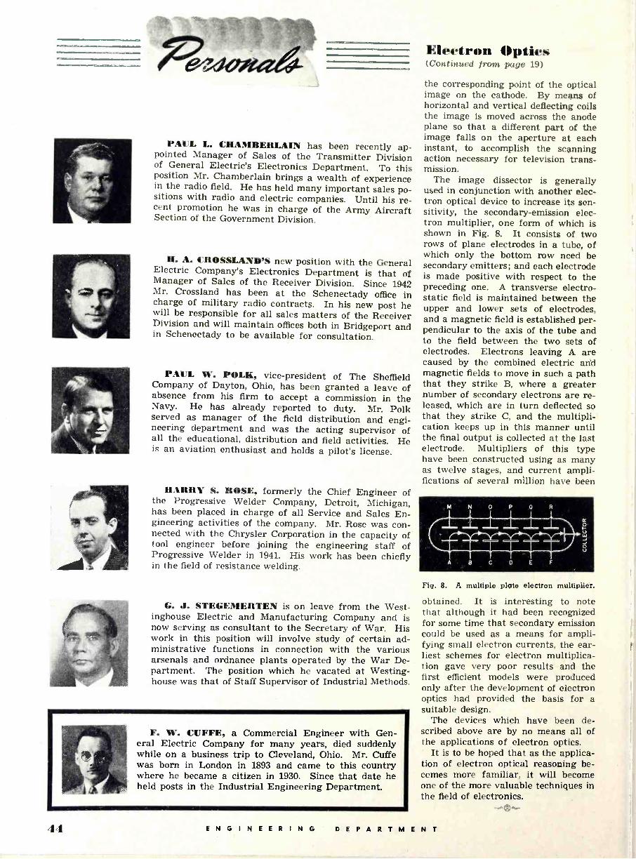
Electron Optics (Continued from page 19)
PAUL L. CHAMBERLAIN has been recently ap- pointed Manager of Sales of the Transmitter Division of General Electric's Electronics Department. To this position Mr. Chamberlain brings a wealth of experience in the radio field. He has held many important sales po- sitions with radio and electric companies. Until his re- cent promotion he was in charge of the Army Aircraft Section of the Government Division.
H. A. CROSSLAND'S new position with the General Electric Company's Electronics Department is that of Manager of Sales of the Receiver Division. Since 1942 Mr. Crossland has been at the Schenectady office in charge of military radio contracts. In his new post he will be responsible for all sales matters of the Receiver Division and will maintain offices both in Bridgeport and in Schenectady to be available for consultation.
PAUL W. POLK, vice-president of The Sheffield Company of Dayton, Ohio, has been granted a leave of absence from his firm to accept a commission in the Navy. He has already reported to duty. Mr. Polk served as manager of the field distribution and engi- neering department and was the acting supervisor of all the educational, distribution and field activities. He is an aviation enthusiast and holds a pilot's license.
HARRY S. ROSE, formerly the Chief Engineer of the Progressive Welder Company, Detroit, Michigan, has been placed in charge of all Service and Sales En- gineering activities of the company. Mr. Rose was con- nected with the Chrysler Corporation in the capacity of tool engineer before joining the engineering staff of Progressive Welder in 1941. His work has been chiefly in the field of resistance welding.
G. J. STEGEMERTEN is on leave from the West- inghouse Electric and Manufacturing Company and is now serving as consultant to the Secretary of War. His work in this position will involve study of certain ad- ministrative functions in connection with the various arsenals and ordnance plants operated by the War De- partment. The position which he vacated at Westing- house was that of Staff Supervisor of Industrial Methods.
F. W. CUFFE, a Commercial Engineer with Gen- eral Electric Company for many years, died suddenly while on a business trip to Cleveland, Ohio. Mr. Cuffe was born in London in 1893 and came to this country where he became a citizen in 1930. Since that date he held posts in the Industrial Engineering Department.
the corresponding point of the optical image on the cathode. By means of horizontal and vertical deflecting coils the image is moved across the anode plane so that a different part of the image falls on the aperture at each instant, to accomplish the scanning action necessary for television trans- mission.
The image dissector is generally used in conjunction with another elec- tron optical device to increase its sen- sitivity, the secondary -emission elec- tron multiplier, one form of which is shown in Fig. 8. It consists of two rows of plane electrodes in a tube, of which only the bottom row need be secondary emitters; and each electrode is made positive with respect to the preceding one. A transverse electro- static field is maintained between the upper and lower sets of electrodes, and a magnetic field is established per- pendicular to the axis of the tube and to the field between the two sets of electrodes. Electrons leaving A are caused by the combined electric and magnetic fields to move in such a path that they strike B, where a greater number of secondary electrons are re- leased, which are in turn deflected so that they strike C, and the multipli- cation keeps up in this manner until the final output is collected at the last electrode. Multipliers of this type have been constructed using as many as twelve stages, and current ampli- fications of several million have been
Fig. 8. A multiple plate electron multiplier.
obtained. It is interesting to note that although it had been recognized for some time that secondary emission could be used as a means for ampli- fying small electron currents, the ear- liest schemes for electron multiplica- tion gave very poor results and the first efficient models were produced only after the development of electron optics had provided the basis for a suitable design.
The devices which have been de- scribed above are by no means all of the applications of electron optics.
It is to be hoped that as the applica- tion of electron optical reasoning be - cernes more familiar, it will become one of the more valuable techniques in the field of electronics.
44 ENGINEERING DEPARTMENT
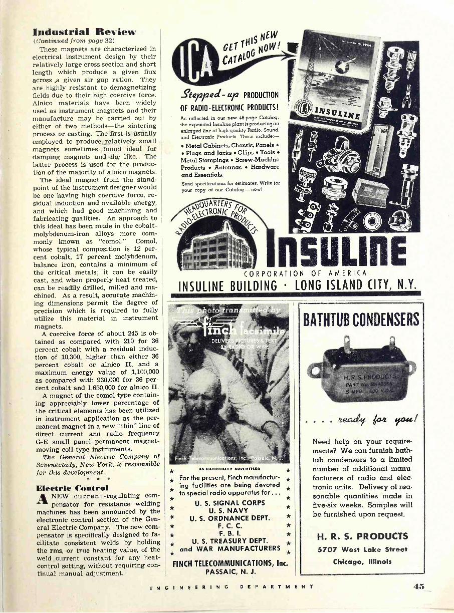
Industrial Review (Continued from page 32)
These magnets are characterized in electrical instrument design by their relatively large cross section and short length which produce a given flux across ,a given air gap ration. They are highly resistant to demagnetizing fields due to their high coercive force. Alnico materials have been widely used as instrument magnets and their manufacture may be carried out by either of two methods-the sintering process, or casting. The first is usually employed to produce relatively small magnets sometimes found ideal for damping magnets and the like. The latter process is used for the produc- tion of the majority of alnico magnets.
The ideal magnet from the stand- point of the instrument designer would be one having high coercive force, re- sidual induction and available energy, and which had good machining and fabricating qualities. An approach to this ideal has been made in the cobalt - molybdenum -iron alloys more com- monly known as "comol." Comol, whose typical composition is 12 per- cent cobalt, 17 percent molybdenum, balance iron, contains a minimum of the critical metals; it can be easily cast, and when properly heat treated, can be readily drilled, milled and ma- chined. As a result, accurate machin- ing dimensions permit the degree of precision which is required to fully utilize this material in instrument magnets.
A coercive force of about 245 is ob- tained as compared with 210 for 36 percent cobalt with a residual induc- tion of 10,300, higher than either 36 percent cobalt or alnico II, and a maximum energy value of 1,100,000 as compared with 930,000 for 36 per- cent cobalt and 1,650,000 for alnico II.
A magnet of the comol type contain- ing appreciably lower percentage of the critical elements has been utilized in instrument application as the per- manent magnet in a new "thin" line of direct current and radio frequency G -E small panel permanent magnet - moving coil type instruments.
The General Electric Company of Schenectady, New York, is responsible for this development.
* * *
Electric Control ANEW current -regulating com-
pensator for resistance welding machines has been announced by the electronic control section of the Gen- eral Electric Company. The new com- pensator is specifically designed to fa- cilitate consistent welds by holding the rms, or true heating value, of the weld current constant for any heat - control setting, without requiring con- tinual manual adjustment.
GEr TNGIS NO "'WW1
CAtAO
ßerreá- up PRODUCTION
OF RADIO -ELECTRONIC PRODUCTS!
As reflected in our new 48 -page Catalog, the expanded Insuline plant is producing an enlarged line of high -quality Radio, Sound, and Electronic Products. These include:
Metal Cabinets, Chassis, Panels Plugs and Jacks Clips Tools
Metal Stampings Screw -Machine Products Antennas Hardware and Essentials. Send specifications for estimates. Write for your copy of our Catalog-nowl
5 u LI CORPORATION OF AMERICA
INSULINE BUILDING LONG ISLAND CITY, N.Y.
n E
AS NATIONALLY ADVERTISED * * For the present, Finch manufactur-
ing facilities are being devoted * to special radio apparatus for ...
*
* *
U. S. SIGNAL CORPS * U. S. NAVY * U. S. ORDNANCE DEPT. *
* F. C. C. * * F. B. I. * * U. S. TREASURY DEPT.
and WAR MANUFACTURERS * * *
FINCH TELECOMMUNICATIONS, Inc. PASSAIC, N. J.
BATHTUB CONDENSERS
..1ecsde 604 e044!
Need help on your require- ments? We can furnish bath- tub condensers to a limited number of additional manu- facturers of radio and elec- tronic units. Delivery of rea- sonable quantities made in five -six weeks. Samples will be furnished upon request.
H. R. S. PRODUCTS 5707 West Lake Street
Chicago, Illinois
ENGINEERING DEPARTMENT i.
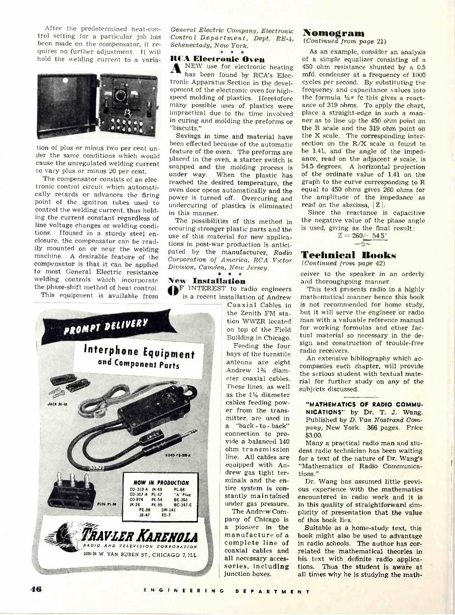
After the predetermined heat -con- trol setting for a particular job has been made on the compensator, it re- quires no further adjustment. It will hold the welding current to a varia-
tion of plus or minus two per cent un- der the same conditions which would cause the unregulated welding current to vary plus or minus 20 per cent.
The compensator consists of an elec- tronic control circuit which automati- cally retards or advances the firing point of the ignitron tubes used to control the welding current, thus hold- ing the current constant regardless of line voltage changes or welding condi- tions. Housed in a sturdy steel en- closure, the compensator can be read- ily mounted on or near the welding machine. A desirable feature of the compensator is that it can be applied to most General Electric resistance welding controls which incorporate the phase -shift method of heat control.
This equipment is available from
JACK 1K-44
General Electric Company, Electronic Control Department, Dept. RE -4, Schenectady, New York.
114' 4 Electronic Oven ANEW use for electronic heating
has been found by RCA's Elec- tronic Apparatus Section in the devel- opment of the electronic oven for high- speed molding of plastics. Heretofore many possible uses of plastics were impractical due to the time involved in curing and molding the preforms or "biscuits."
Savings in time and material have been effected because of the automatic feature of the oven. The preforms are placed in the oven, a starter switch is snapped and the molding process is under way. When the plastic has reached the desired temperature, the oven door opens automatically and the power is turned off. Overcuring and undercuring of plastics is eliminated in this manner.
The possibilities of this method in securing stronger plastic parts and the use of this material for new applica- tions in post-war production is antici- pated by the manufacturer, Radio Corporation of America, RCA Victor Division, Camden, New Jersey.
New Installation OF INTEREST to radio engineers is a recent installation of Andrew
Coaxial Cables in the Zenith FM sta- tion WWZR located on top of the Field Building in Chicago.
Feeding the four bays of the turnstile antenna are eight Andrew 1% diam- eter coaxial cables. These lines, as well as the 4% diameter cables feeding pow- er from the trans- mitter, are used in a "back - to - back" connection to pro- vide a balanced 140 ohm transmission line. All cables are equipped with An- drew gas tight ter- minals and the en- tire system is con- stantly maintained under gas pressure.
The Andrew Com- pany of Chicago is a pioneer in the manufacture of a complete line of coaxial cables and all necessary acces- sories, including junction boxes.
Interphone Equipment and Component Parts
PLUG PL -58
NOW IN PRODUCTION CD- 318-A 1K-48 PL -68 CD -307A PL -47 "A" Plug CD -874 PL -54 BC -366 1K-26 PL -5S BC -347-C
PE -86 SW -141 18-47 TD -3
RADIO AND TELEVISION CORPORATION 1030-36 W. VAN BUREN ST., CHICAGO 7, ILL.
'Nomogram (Continued from page 21)
As an example, consider an analysis of a simple equalizer consisting of a 450 ohm resistance shunted by a 0.5 mfd. condenser at a frequency of 1000 cycles per second. By substituting the frequency and capacitance values into the formula %ir fc this gives a react- ance of 319 ohms. To apply the chart, place a straight -edge in such a man- ner as to line up the 450 ohm point on the R scale and the 319 ohm point on the X scale. The corresponding inter- section on the R/X scale is found to be 1.41, and the angle of the imped- ance, read on the adjacent 9 scale, is 54.5 degrees. A horizontal projection of the ordinate value of 1.41 on the graph to the curve corresponding to R equal to 450 ohms gives 260 ohms for the amplitude of the impedance as read on the abscissa, I Z I.
Since the reactance is capacitive the negative value of the phase angle is used, giving as the final result:
Z = 260/-54.5°
Technical Books (Continued from page 42)
ceiver to the speaker in an orderly and thoroughgoing manner.
This text presents radio in a highly mathematical manner hence this book is not recommended for home study, but it will serve the engineer or radio man with a valuable reference manual for working formulas and other fac- tual material so necessary in the de- sign and construction of trouble -free radio receivers.
An extensive bibliography which ac- companies each chapter, will provide the serious student with textual mate- rial for further study on any of the subjects discussed.
"MATHEMATICS OF RADIO COMMU- NICATIONS" by Dr. T. J. Wang. Published by D. Van Nostrand Com- pany, New York. 366 pages. Price $3.00. Many a practical radio man and stu-
dent radio technician has been waiting for a text of the nature of Dr. Wang's "Mathematics of Radio Communica- tions."
Dr. Wang has assumed little previ- ous experience with the mathematics encountered in radio work and it is in this quality of straightforward sim- plicity of presentation that the value of this book lies.
Suitable as a home -study text, this book might also be used to advantage in radio schools. The author has cor- related the mathematical theories in his text with definite radio applica- tions. Thus the student is aware at all times why he is studying the math -
46 ENGINEERING DEPARTMENT
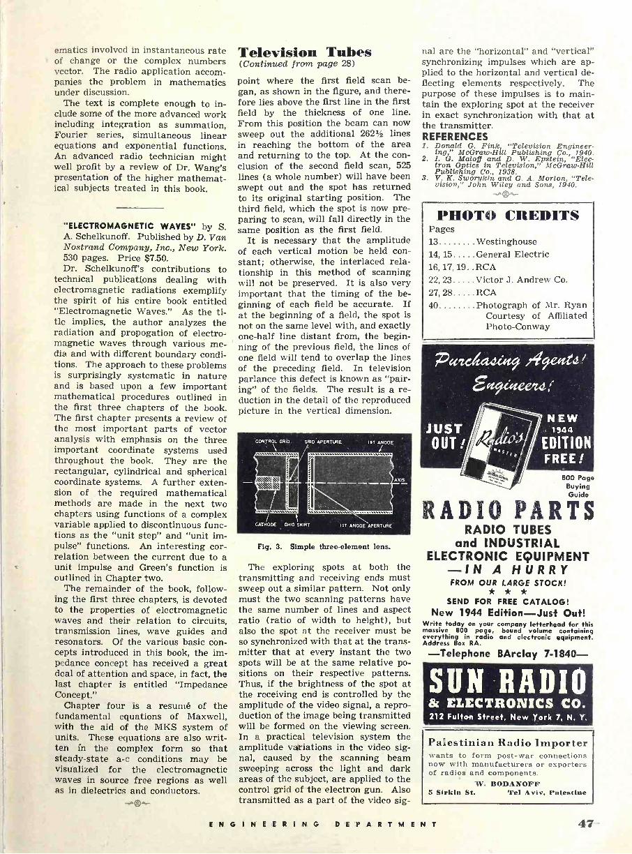
ematics involved in instantaneous rate of change or the complex numbers vector. The radio application accom- panies the problem in mathematics under discussion.
The text is complete enough to in- clude some of the more advanced work including integration as summation, Fourier series, simultaneous linear equations and exponential functions. An advanced radio technician might well profit by a review of Dr. Wang's presentation of the higher mathemat- ical subjects treated in this book.
"ELECTROMAGNETIC WAVES" by S. A. Schelkunoff. Published by D. Van Nostrand Company, Inc., New York. 530 pages. Price $7.50. Dr. Schelkunoff's contributions to
technical publications dealing with electromagnetic radiations exemplify the spirit of his entire book entitled "Electromagnetic Waves." As the ti- tle implies, the author analyzes the radiation and propogation of electro- magnetic waves through various me- dia and with different boundary condi- tions. The approach to these problems is surprisingly systematic in nature and is based upon a few important mathematical procedures outlined in the first three chapters of the book. The first chapter presents a review of the most important parts of vector analysis with emphasis on the three important coordinate systems used throughout the book. They are the rectangular, cylindrical and spherical coordinate systems. A further exten- sion of the required mathematical methods are made in the next two chapters using functions of a complex variable applied to discontinuous func- tions as the "unit step" and "unit im- pulse" functions. An interesting cor- relation between the current due to a unit impulse and Green's function is outlined in Chapter two.
The remainder of the book, follow- ing the first three chapters, is devoted to the properties of electromagnetic waves and their relation to circuits, transmission lines, wave guides and resonators. Of the various basic cón- cepts introduced in this book, the im- pedance concept has received a great deal of attention and space, in fact, the last chapter is entitled "Impedance Concept."
Chapter four is a resumé of the fundamental equations of Maxwell, with the aid of the MKS system of units. These equations are also writ- ten in the complex form so that steady-state a -c conditions may be visualized for the electromagnetic waves in source free regions as well as In dielectrics and conductors.
Television Tubes (Continued from page 28)
point where the first field scan be- gan, as shown in the figure, and there- fore lies above the first line in the first field by the thickness of one line. From this position the beam can now sweep out the additional 262í/a lines in reaching the bottom of the area and returning to the top. At the con- clusion of the second field scan, 525 lines (a whole number) will have been swept out and the spot has returned to its original starting position. The third field, which the spot is now pre- paring to scan, will fall directly in the same position as the first field.
It is necessary that the amplitude of each vertical motion be held con- stant; otherwise, the interlaced rela- tionship in this method of scanning will not be preserved. It is also very important that the timing of the be- ginning of each field be accurate. If at the beginning of a field, the spot is not on the same level with, and exactly one-half line distant from, the begin- ning of the previous field, the lines of one field will tend to overlap the lines of the preceding field. In television parlance this defect is known as "pair- ing" of the fields. The result is a re- duction in the detail of the reproduced picture in the vertical dimension.
CONTROL GRID GRID APERTURE 1ST
/ANODE /
AXIS
CATHODE GRID SKIRT IsT ANODEAPERTURE
Fig. 3. Simple three -element lens.
The exploring spots at both the transmitting and receiving ends must sweep out a similar pattern. Not only must the two scanning patterns have the same number of lines and aspect ratio (ratio of width to height), but also the spot at the receiver must be so synchronized with that at the trans- mitter that at every instant the two spots will be at the same relative po- sitions on their respective patterns. Thus, if the brightness of the spot at the receiving end is controlled by the amplitude of the video signal, a repro- duction of the image being transmitted will be formed on the viewing screen. In a practical television system the amplitude valriations in the video sig- nal, caused by . the scanning beam sweeping across the light and dark areas of the subject, are applied to the control grid of the electron gun. Also transmitted as a part of the video sig-
nal are the "horizontal" and "vertical" synchronizing impulses which are ap- plied to the horizontal and vertical de- flecting elements respectively. The purpose of these impulses is to main- tain the exploring spot at the receiver in exact synchronization with that at the transmitter. REFERENCES 1. Donald G. Fink "Television Engineer-
ing," McGraw-Hill Publishing Co., 1940. 2. I. G. Maloff and D. W. Epstein, "Elec-
tron Optics in Television," McGraw-Hill Publishing Co., 1938.
3. V. K. Sworykin and G. A. Morton, "Tele- vision," John Wiley and Sons, 1940.
PHOTO CREDITS Pages 13 Westinghouse 14, 15 General Electric 16, 17, 19. . RCA 22, 23 Victor J. Andrew Co.
27, 28 RCA 40 Photograph of Mr. Ryan
Courtesy of Affiliated Photo -Conway
800 Page Buying Guide
RADIO PARTS RADIO TUBES
and INDUSTRIAL ELECTRONIC EQUIPMENT -IN A HURRY
FROM OUR LARGE STOCK! * * *
SEND FOR FREE CATALOG! New 1944 Edition-Just Out!
Write today on your company letterhead for this massive 800 page, bound volume containing everything in radio and electronic equipment. Address Box RA.
-Telephone BArclay 7-1840-
SUN RADIO & ELECTRONICS CO. 212 Fulton Street, New York 7, N. Y.
Palestinian Radio Importer wants to form post-war connections now with manufacturers or exporters of radios and components.
W. BODANOFF 5 Sirkin St. Tel Aviv, Palestine
ENGINEERING DEPARTMENT 47-

WHEN SPECIFICATIONS CALL FOR STEATITE . . .
LENOXITE DIVISION LENOX INCORPORATED TRENTON, NEW JERSEY
48 ENGINEERING DEPARTMENT


