Application Note R11AN0230EJ0310 Rev.03.10 Page 1 of 27 Sep. 20, 2021 Radio Evaluation Program Commands Reference Introduction This document is AT Command Reference Manual regarding Radio Evaluation Program. Radio Evaluation Program is radio control firmware for RL78/G23 and RL78/G14 MCU with Semtech RF Transceiver SX1261/SX1262 with LoRa ® Technology. NOTE: This software is free of charge and no guarantee, and also provided as evaluation purpose only. Version V3.10 or later Feature - Supports LoRa modulation and FSK modulation. - Supports User Command Interface based on AT commands format. - Supports unmodulated and modulated wave transmission. - Supports packet transmission with 4 type of payload data (PN9, DevEUI, and user defined data, Sensor). - Supports continuous or single packet reception. - Supports the LBT(Listen Before Talk), ED(Energy detection) and ToA(Time on Air) Calculation. - Supports Japan radio regulation (ARIB-STD-T108) Target Devices MCU: Renesas RL78/G23(R7F100GLG, R7F100GSN) or RL78/G14 (R5F104ML) Transceiver: Semtech SX1261(max:+15dBm) or SX1262(max:+22dBm) Sensor: Renesas HS3001/HS3002/HS3003/HS3004(Humidity and Temperature Sensor) Target Devices RL78/G23 or RL78/G14 + SX1261 or SX1262 Serial / UART AT Commands
Transcript
Application Note
R11AN0230EJ0310 Rev.03.10 Page 1 of 27 Sep. 20, 2021
Radio Evaluation Program Commands Reference Introduction This document is AT Command Reference Manual regarding Radio Evaluation Program. Radio Evaluation Program is
radio control firmware for RL78/G23 and RL78/G14 MCU with Semtech RF Transceiver SX1261/SX1262 with LoRa® Technology.
NOTE: This software is free of charge and no guarantee, and also provided as evaluation purpose only.
Version V3.10 or later
Feature - Supports LoRa modulation and FSK modulation.
- Supports User Command Interface based on AT commands format.
- Supports unmodulated and modulated wave transmission.
- Supports packet transmission with 4 type of payload data (PN9, DevEUI, and user defined data, Sensor).
- Supports continuous or single packet reception.
- Supports the LBT(Listen Before Talk), ED(Energy detection) and ToA(Time on Air) Calculation.
- Supports Japan radio regulation (ARIB-STD-T108)
Target Devices MCU: Renesas RL78/G23(R7F100GLG, R7F100GSN) or RL78/G14 (R5F104ML)
Transceiver: Semtech SX1261(max:+15dBm) or SX1262(max:+22dBm)
Sensor: Renesas HS3001/HS3002/HS3003/HS3004(Humidity and Temperature Sensor)
Target Devices RL78/G23 or RL78/G14
+ SX1261 or SX1262
Serial / UART
AT Commands
Radio Evaluation Program Commands Reference
R11AN0230EJ0310 Rev.03.10 Page 2 of 27 Sep. 20, 2021
Index
1. Getting started .................................................................................................................. 4 1.1 Setup the Radio Evaluation Program ........................................................................................ 4 1.2 Serial/UART Interface Configuration ......................................................................................... 4
4. Example Scripts ............................................................................................................. 26 4.1 Simple script for LoRa .............................................................................................................. 26 4.2 PER Test script for LoRa .......................................................................................................... 27 4.3 BER Test script for FSK ........................................................................................................... 27
Radio Evaluation Program Commands Reference
R11AN0230EJ0310 Rev.03.10 Page 4 of 27 Sep. 20, 2021
1. Getting started
1.1 Setup the Radio Evaluation Program Please refer to the Quick Start Guide located in,
1.2 Serial/UART Interface Configuration The settings for the Serial/UART interface are shown in Table 1.
Table 1. Serial/UART interface Configuration
Configuration Items Value Baud rate 115200 bps Data bit 8 bits Parity bit None Stop bit 1 bit Flow control None Local echo back Yes Line terminator Transmission: CR+LF
Reception: CR+LF
1.3 Sensor/I2C Interface Configuration (Optional) If you need to send the sensor values as payload data, you have to connect the HS3001/2/3/4 (Humidity and Temperature Sensor) to IICA(I2C) interface and define the macro “RP_USE_IICA” as build options (default). IICA(I2C) interface for the sensor is IICA1(RL78/G23) or IICA0(RL78/G14).
Radio Evaluation Program Commands Reference
R11AN0230EJ0310 Rev.03.10 Page 5 of 27 Sep. 20, 2021
2. AT Command syntax 2.1 Definitions The following syntactical definitions apply:
<CR> Carriage return character like as “\r”.
<LF> Linefeed character like as “\n”.
<…> Name enclosed in angle brackets is a syntactical element.
[…] Optional parameter of a command. Brackets themselves do not appear in the command line.
2.2 Syntax 2.2.1 General command syntax The prefix “AT” or “at” (no case sensitive) should be included at the beginning of each command line. All commands need to be terminated by <CR><LF>. A new command must not be issued before this firmware has terminated all the sending of its response result code (e.g. “OK”). All commands are no case sensitive. 2.2.2 Command syntax The format of Extended Command has several formats, as following table:
Table 2. Extended Command Syntax: Action Command Type Syntax Description Example Get AT+<name>? Get current parameter settings. AT+FREQ? Set AT+<name>=<params> Set new parameters. AT+TXPWR=10 Action AT+<name> Execute without parameters. AT+SEND Set & Action AT+<name>=<params> Execute with parameters. AT+RECV=0
2.2.3 Response syntax The command responses are consisted in the <Information Response> and <Result Code> described as below:
<CR><LF><Information Response><CR><LF> for Extended Command only
<CR><LF><Result Code><CR><LF> for Basic and Extended Command
Where <Information Response> syntax is “+<command>:<messages>”. E.g. “+FREQ:923000000”.
Where <Result Code> syntax is “OK”, “ERROR” or “BUSY”.
“OK”: Command run correctly without error.
“ERROR”: Command is cancelled with error (e.g. command format error, parameter out of range, and so on.).
“BUSY”: Command is cancelled because the previous command is still running.
Radio Evaluation Program Commands Reference
R11AN0230EJ0310 Rev.03.10 Page 6 of 27 Sep. 20, 2021
3. AT Commands
Type Command Description State INIT AT Test serial connection. ANY AT+RESET Reset and load all settings from data flash memory. ANY RF AT+MODEM Set modem type (LoRa or FSK). IDLE AT+FREQ Set the radio center frequency. IDLE AT+LMCFG Set LoRa modulation parameters. IDLE AT+LPCFG Set LoRa packet parameters. IDLE AT+FMCFG Set FSK modulation parameters. IDLE AT+FPCFG Set FSK packet parameters. IDLE TX AT+SEND Start transmitting the packets. IDLE AT+TXPWR Set Tx output power IDLE AT+TXTO Set Tx timeout. IDLE AT+PKT Set Tx packet data / Set Rx expected data for PER/BER test. IDLE AT+LBT Set LBT (Listen Before Talk) parameters / Test LBT IDLE AT+TXCW Start transmitting the unmodulated continuous wave. IDLE AT+TXCP Start transmitting the modulated continuous wave. IDLE RX AT+RECV Start receiving the packets. IDLE AT+RXTO Set Rx timeout and Symbol timeout. IDLE AT+RXGAIN Set Rx gain mode. IDLE AT+RSSI Set RSSI offset / Show instantaneous RSSI value. IDLE CTRL AT+STOP Stop Tx and Rx / Show the statistical result of Rx. ANY AT+STAT Show the current state of the program. ANY UTIL AT+XTRIM Set XTAL trimming register to adjust radio center frequency. IDLE AT+SAFE Set safe mode to support Japanese radio regulation. IDLE AT+TOA Show the time on air. IDLE AT+REGW Write RF device register. ANY AT+REGR Read RF device register. ANY AT+SLEEP Test sleep mode. IDLE AT+DEVEUI Set the Device EUI (MAC Address). IDLE AT+SAVE Store all settings into the data flash memory. IDLE AT+ERASE Erase data flash memory and store system default settings. IDLE AT+HELP Show the usage of AT commands. ANY AT+LIST Show the current settings. ANY AT+VER Show the program version. ANY
Radio Evaluation Program Commands Reference
R11AN0230EJ0310 Rev.03.10 Page 7 of 27 Sep. 20, 2021
3.1 AT Commands Sequence AT Command should be issued as following sequence because some AT Command has dependency each other.
This command starts transmitting the packets with delay until reaching the limit or sending “AT+STOP”. The packet payload is specified by “AT+PKT”. The limit is specified by parameter <pktNum>. The packet delay is specified by parameter <pktDelay>. If no parameter is specified, this command will be performed with latest parameter settings. While sending packets, if Tx timeout specified by “AT+TXTO” is expired, indication will be reported with “+INFO:TX_TIMEOUT”.
No additional information is reported. It’s for PER/BER test. 1: Verbose Mode (default) Reports current sequence number (see [Response])
[Response]
Response +TX:<seqNum> <seqNum> current sequence number (1 .. <pktNum>)
[Result codes]
OK, ERROR or BUSY
Radio Evaluation Program Commands Reference
R11AN0230EJ0310 Rev.03.10 Page 14 of 27 Sep. 20, 2021
3.2.10 AT+TXPWR [Command syntax]
AT+TXPWR=<txPower> AT+TXPWR?
[Description]
This command specifies the transmission power for LoRa and FSK.
[Parameters]
<txPower> SX1261: -17 ~ 15[dBm] in decimal (default 14[dBm]) SX1262: -9 ~ 22[dBm] in decimal (default 14[dBm])
[Result codes]
OK, ERROR or BUSY
3.2.11 AT+TXTO [Command syntax]
+TXTO=<txTimeout> +TXTO?
[Description]
This command sets the transmission command timeout duration of the single packet for the current modem. Therefore, the setting for LoRa and FSK can be specified separately.
R11AN0230EJ0310 Rev.03.10 Page 15 of 27 Sep. 20, 2021
3.2.12 AT+PKT [Command syntax]
AT+PKT=<payloadType> , <payloadLen> or <payloadData> AT+PKT?
[Description]
This command specifies the transmission data and expected reception data for PER/BER testing.
[Parameters]
<payloadType> 1: PER (default) Pre-defined payload data for PER test. Format: “PER”(504552) + Sequence Number(4bytes) + PN9(binary) Length: <payloadLen>
2: BER Pre-defined payload data for BER test. Format: PN9(binary) Length: <payloadLen>
3: ANY User defined payload data specified by <payloadData> in hex. Length: bytes of <payloadData>
4: EUI Pre-defined payload data including the Device EUI. Format: “EUI(455549) + Device EUI(8bytes) + PN9(binary) Length: <payloadLen>
5: EXT(Sensor) Sensor values with ID (ID is lowest byte of the Device EUI) Format: ID(1byte) + Humidity(2bytes) + Temperature(2bytes)
Humidity: uint16_t unit 0.1%, Temperature: int16_t unit 0.1°C Length: <payloadLen> (Len < 5: truncated. Len > 5: padding 0x00) Note: The sensor takes 4 seconds to measure.
<payloadLen> The payload length for <payloadType> = 1(PER) or 2(BER) or 4(EUI). 0 ~ 255 in decimal (default 16)
<payloadData> The payload data for <payloadType> = 3(ANY) 1 ~ 255 [bytes] in hex (e.g. see [Examples]).
[Result codes]
OK, ERROR or BUSY
[Examples]
AT+PKT=03,112233445566778899AABBCCDDEEFF OK
The pre-defined payload for PER/BER The pre-defined payload (max 255 [bytes], sending/receiving MSB first) PN9 data FF83DF1732094ED1E7CD8A91C6D5C4C44021184E5586F4DC8A15A7EC92DF93533018
This command set the LBT(Listen Before Talk) parameters. If the LBT is enabled while energy is detected on the air, the transmission will be canceled and will be re-scheduled at the next transmission). If no parameter is specified, this command will perform carrier sense to detect energy and return result (see [Response]).
[Parameters]
<lbtEnable> 0: Disables the LBT (default) 1: Enables the LBT.
<rssiThreshold > 0 ~ -128 [dBm] (default -80 [dBm]) <ccaDuration> 1 ~ 10 [ms] (default 5 [ms]) <ccaBandWidth> 0: Use the bandwidth specified by “AT+FMCFG/LMCFG” (default)
Response(Action) +LBT:<detection>,<rssiValue> <detection> 0: Not detected
1: Detected <rssiValue> 0 ~ -127 [dBm]
[Result codes]
OK, ERROR or BUSY
Radio Evaluation Program Commands Reference
R11AN0230EJ0310 Rev.03.10 Page 17 of 27 Sep. 20, 2021
3.2.14 AT+TXCW [Command syntax]
+TXCW
[Description]
This command transmits the unmodulated continuous wave until “AT+STOP” command is sent. If safe mode is enabled (AT+SAFE=1), this command will return ERROR.
[Result codes]
OK, ERROR or BUSY 3.2.15 AT+TXCP [Command syntax]
+TXCP
[Description]
This command transmits the modulated wave until “AT+STOP command is sent”. If safe mode is enabled (AT+SAFE=1), this command will return ERROR.
[Result codes]
OK, ERROR or BUSY
Radio Evaluation Program Commands Reference
R11AN0230EJ0310 Rev.03.10 Page 18 of 27 Sep. 20, 2021
3.2.16 AT+RECV [Command syntax]
AT+RECV=<rxMode>[,<verboseMode>] AT+RECV? AT+RECV
[Description]
This command starts receiving the packets. If no parameter is specified, this command will be performed with latest parameter settings.
[Parameters]
<rxMode> 0: Continuous Rx Mode (default) Repeats single Rx with no Rx timeout until “AT+STOP” is sent. 1: Single Rx Mode Performs single Rx with Rx timeout specified by “AT+RXTO”. If Rx timeout is expired, indication will be reported as below. +INFO:RX_TIMEOUT
<verboseMode> 0: Silent Mode No additional information is reported. It’s for PER/BER test. 1: Verbose Mode (default) Received packet information is reported (see [Response])
This command specifies the Rx Gain mode for both LoRa and FSK.
[Parameters]
<gainMode> 0: Rx Power Saving Gain mode (default) 1: Rx Boosted Gain mode
[Result codes]
OK, ERROR or BUSY
Radio Evaluation Program Commands Reference
R11AN0230EJ0310 Rev.03.10 Page 19 of 27 Sep. 20, 2021
3.2.18 AT+RXTO [Command syntax]
AT+RXTO=<rxTimeout>[,<symbolTimeout>] AT+RXTO?
[Description]
This command specifies the reception timeout and symbol timeout. The symbol timeout setting for LoRa and FSK can be specified separately.
[Parameters]
<rxTimeout> 1~ 65535 [ms] (default 1000[ms] ) <symbolTimeout> 1 ~ 255 [symbols] in decimal (default 5[symbols] ) for LoRa
1 ~ 65535 [bytes] in decimal (default 5[bytes] ) for FSK [Result codes]
OK, ERROR or BUSY
3.2.19 AT+RSSI [Command syntax]
AT+RSSI=<rssiOffset> AT+RSSI? AT+RSSI
[Description]
This command sets the offset of the RSSI value. If no parameter is specified, this command reports the instantaneous RSSI using FSK modem. Before using this command, AT+MODEM=0(FSK) is required.
R11AN0230EJ0310 Rev.03.10 Page 20 of 27 Sep. 20, 2021
3.2.20 AT+STOP [Command syntax]
AT+STOP
[Description]
This command stops transmitting and receiving. In the reception state, this command returns the statistical information response regarding received packets.
<totalPkts> Number of the total received packets <okPkts> Number of the received packets with no CRC error <ngPkts> Number of the received packets with CRC error <totalBits> Number of the total bits of the received packets. Fixed to 0 when AT+PKT=1. <okBits> Number of the same bits specified by AT+PKT=2|3|4. 0 when AT+PKT=1. <ngBits> Number of the different bits specified by AT+PKT=2|3|4. 0 when AT+PKT=1. <rssiAve> Average RSSI [dBm] <rssiMin> Minimum RSSI [dBm] <rssiMax> Maximum RSSI [dBm] <snrAve> Average SNR[dBm] (for LoRa only, 0 in FSK.) <snrMin> Minimum SNR[dBm] (for LoRa only, 0 in FSK.) <snrMax> Maximum SNR[dBm] (for LoRa only, 0 in FSK.)
[Result codes]
OK or ERROR
[Notes]
To perform PER/BER test, the same RF setting is required for sender and receiver side. The CRC is required in PER test to count packets properly. On the other hand, the CRC should not be included in the packet in the BER test because the CRC is removed before counting received bits, it makes mismatch between the received bits and the expected bits.
Radio Evaluation Program Commands Reference
R11AN0230EJ0310 Rev.03.10 Page 21 of 27 Sep. 20, 2021
3.2.21 AT+STAT [Command syntax]
AT+STAT
[Description]
This command reports the current program state and Tx/Rx progress
[Response]
Response +STAT:<state> <state> IDLE
Waiting for the new AT commands. TX,<Number of packets sent> AT+SEND command is running. RX,<Number of packets received> AT+RECV command is running. CX AT+TXCW or AT+TXCP command is running.
[Result codes]
OK or BUSY
3.2.22 AT+XTRIM [Command syntax]
AT+XTRIM=<xtaTrim>,<xtbTrim> AT+XTRIM?
[Description]
This command specifies the internal foot capacitance for the XTAL to adjust the center frequency.For more detail, please refer to the section “XTAL Control Block” in the SX1261/SX1262 datasheet.
[Parameters]
<xtaTrim> The internal foot capacitor setting for XTA 00 ~ 2F (11.3 ~ 33.4 step 0.47 [pF]) in hex (default 13)
<xtbTrim> The internal foot capacitor setting for XTB 00 ~ 2F (11.3 ~ 33.4 step 0.47 [pF]) in hex (default 13)
[Result codes]
OK, ERROR or BUSY
Radio Evaluation Program Commands Reference
R11AN0230EJ0310 Rev.03.10 Page 22 of 27 Sep. 20, 2021
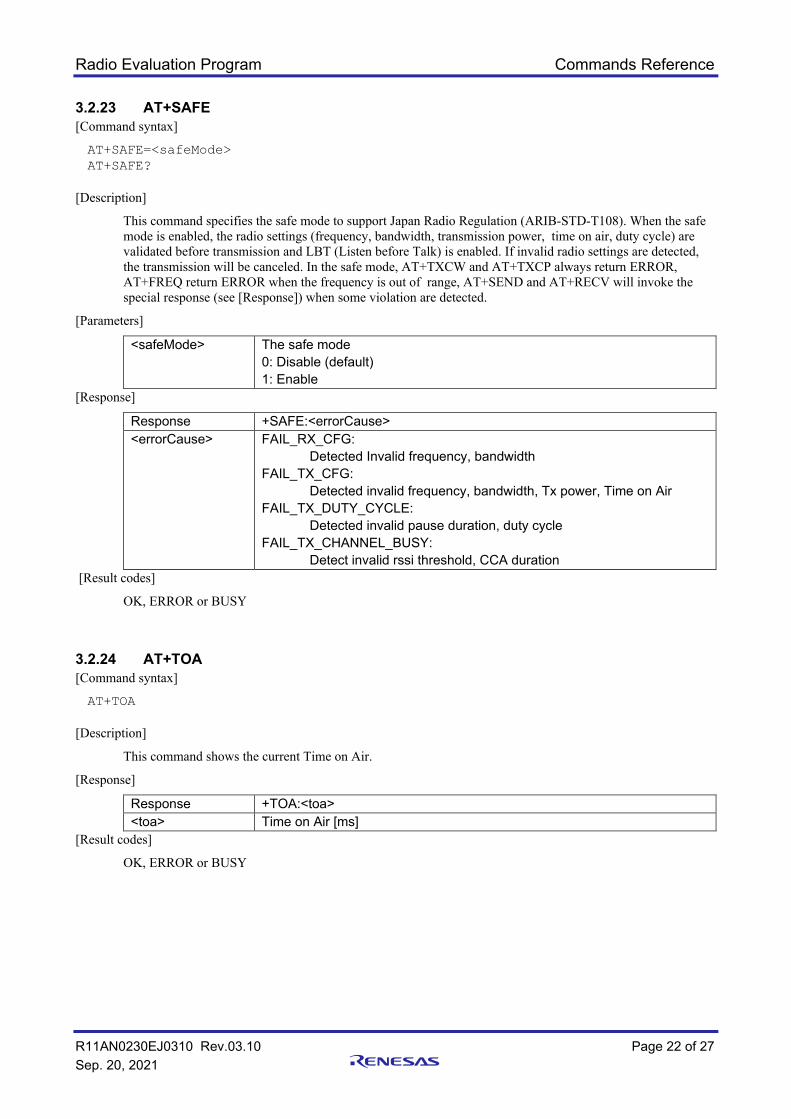
3.2.23 AT+SAFE [Command syntax]
AT+SAFE=<safeMode> AT+SAFE?
[Description]
This command specifies the safe mode to support Japan Radio Regulation (ARIB-STD-T108). When the safe mode is enabled, the radio settings (frequency, bandwidth, transmission power, time on air, duty cycle) are validated before transmission and LBT (Listen before Talk) is enabled. If invalid radio settings are detected, the transmission will be canceled. In the safe mode, AT+TXCW and AT+TXCP always return ERROR, AT+FREQ return ERROR when the frequency is out of range, AT+SEND and AT+RECV will invoke the special response (see [Response]) when some violation are detected.
[Parameters]
<safeMode> The safe mode 0: Disable (default) 1: Enable
This command writes the device registers in SX1261/SX1262.
[Parameters]
<address> 0000 ~ FFFF: The start address of the register in hex. <byte1>,…<byteN> The write data in hex (comma-separated), N: 1 ~ 8
[Result codes]
OK or ERROR
3.2.27 AT+SLEEP [Command syntax]
AT+SLEEP=<sleepMode>,<sleepPeriod> AT+SLEEP?
[Description]
This command tests sleep mode.
[Parameters]
<sleepMode> The sleep mode (SX1261/SX1262) in decimal 0: Cold sleep mode 1: Warm sleep mode (default)
<sleepPeriod> The sleep duration 1 ~ 1000 [s] in decimal (default 10[s]) 0: Infinite (This mode can be canceled by pressing the reset switch.) When infinite sleep mode is specified, the 32-bit interval timer of RL78/G23 will stop, but the RTC and 12-bit interval timer of RL78/G14 will not.
[Result codes]
OK, ERROR or BUSY
Radio Evaluation Program Commands Reference
R11AN0230EJ0310 Rev.03.10 Page 24 of 27 Sep. 20, 2021
3.2.28 AT+DEVEUI [Command syntax]
AT+DEVEUI=<devEui> AT+DEVEUI?
[Description]
This command sets the Device EUI.
[Parameters]
<devEui> 8bytes in hex (default 0123456789ABCDEF) [Result codes]
OK, ERROR or BUSY 3.2.29 AT+SAVE [Command syntax]
AT+SAVE
[Description]
This command saves the all settings to the data flash memory. The saved settings will be automatically loaded at the next start-up (power-on-reset, reset and AT+RESET).
[Result codes]
OK or BUSY
3.2.30 AT+ERASE [Command syntax]
AT+ERASE
[Description]
This command initializes the data flash memory with system default settings and performs a reset.
[Result codes]
OK or BUSY
Radio Evaluation Program Commands Reference
R11AN0230EJ0310 Rev.03.10 Page 25 of 27 Sep. 20, 2021
3.2.31 AT+LIST [Command syntax]
+LIST
[Description]
This command shows the current parameter settings
[Result codes]
OK
3.2.32 AT+HELP [Command syntax]
+HELP
[Description]
This command shows the usage of the all AT commands.
[Result codes]
OK
3.2.33 AT+VER [Command syntax]
+VER?
[Description]
This command shows the program version.
[Result codes]
OK
Radio Evaluation Program Commands Reference
R11AN0230EJ0310 Rev.03.10 Page 26 of 27 Sep. 20, 2021
4. Example Scripts The test environment for the example scripts is shown as below.
4.1 Simple script for LoRa
Sender Receiver Remark
AT+RESET Reset all settings.
AT+RECV=0 Start Rx with continuous Rx mode(0)
AT+SEND=10 Start Tx with 10[packets]
(AT+STOP) Wait for the completion of the Tx , or force to stop Tx.
AT+STOP Stop Rx and report statistical information
Above example is the same as the following example.
Sender Receiver Remark
AT+RESET Reset all settings.
AT+FREQ=923000000
AT+MODEM=1
Frequency: 923[MHz]
Modulation: LoRa(1)
AT+PKT=1,16 Payload is PER format(1), Payload length: 16[bytes]
AT+RECV=0,0 Start Rx with continuous Rx mode(0), silent mode(0)
AT+SEND=100,10,0 Start Tx with 100[packets], Tx delay:10[ms], silent mode(0)
(AT+STOP) Wait for the completion of the Tx , or force to stop Tx.
AT+STOP Stop Rx and report the BER result
Application Note
R11AN0230EJ0310 Rev.03.10 Sep. 20, 2021
Revision History
Rev. Date Description Section Summary
1.00 Jan. 11, 2019 All First official release for Generation 1 2.10 July 1, 2020 All First official release for Generation 2
Generation 1 is based on the Renesas original Radio Driver. Generation 2 is based on the GitHub LoRaMAC-node V4.4.4 reference Radio Driver. Generation 2 is NOT compatible with Generation 1.
2.20 Sep. 16, 2020 1, 4, 15 Supports HS3001/2/3/4 (Humidity and Temperature sensor) Add AT+PKT=5 to send the sensor values as payload data.
3.00 Mar. 5, 2021 1, 4, 26 All
Supports RL78/G23(R7F100GLG) No functional Changes from V2.20
3.01 June 7,2021 23 Add infinite sleep mode on AT+SLEEP. 3.10 Sep. 20, 2021 1, 4
15 Supports RL78/G23(R7F100GSN) Changed the sensor measurement time to 4 seconds.
General Precautions in the Handling of Microprocessing Unit and Microcontroller Unit Products The following usage notes are applicable to all Microprocessing unit and Microcontroller unit products from Renesas. For detailed usage notes on the products covered by this document, refer to the relevant sections of the document as well as any technical updates that have been issued for the products.
1. Precaution against Electrostatic Discharge (ESD)
A strong electrical field, when exposed to a CMOS device, can cause destruction of the gate oxide and ultimately degrade the device operation. Steps must be taken to
stop the generation of static electricity as much as possible, and quickly dissipate it when it occurs. Environmental control must be adequate. When it is dry, a
humidifier should be used. This is recommended to avoid using insulators that can easily build up static electricity. Semiconductor devices must be stored and
transported in an anti-static container, static shielding bag or conductive material. All test and measurement tools including work benches and floors must be
grounded. The operator must also be grounded using a wrist strap. Semiconductor devices must not be touched with bare hands. Similar precautions must be taken for
printed circuit boards with mounted semiconductor devices. 2. Processing at power-on
The state of the product is undefined at the time when power is supplied. The states of internal circuits in the LSI are indeterminate and the states of register settings
and pins are undefined at the time when power is supplied. In a finished product where the reset signal is applied to the external reset pin, the states of pins are not
guaranteed from the time when power is supplied until the reset process is completed. In a similar way, the states of pins in a product that is reset by an on-chip
power-on reset function are not guaranteed from the time when power is supplied until the power reaches the level at which resetting is specified. 3. Input of signal during power-off state
Do not input signals or an I/O pull-up power supply while the device is powered off. The current injection that results from input of such a signal or I/O pull-up power
supply may cause malfunction and the abnormal current that passes in the device at this time may cause degradation of internal elements. Follow the guideline for
input signal during power-off state as described in your product documentation. 4. Handling of unused pins
Handle unused pins in accordance with the directions given under handling of unused pins in the manual. The input pins of CMOS products are generally in the high-
impedance state. In operation with an unused pin in the open-circuit state, extra electromagnetic noise is induced in the vicinity of the LSI, an associated shoot-
through current flows internally, and malfunctions occur due to the false recognition of the pin state as an input signal become possible. 5. Clock signals
After applying a reset, only release the reset line after the operating clock signal becomes stable. When switching the clock signal during program execution, wait
until the target clock signal is stabilized. When the clock signal is generated with an external resonator or from an external oscillator during a reset, ensure that the
reset line is only released after full stabilization of the clock signal. Additionally, when switching to a clock signal produced with an external resonator or by an
external oscillator while program execution is in progress, wait until the target clock signal is stable. 6. Voltage application waveform at input pin
Waveform distortion due to input noise or a reflected wave may cause malfunction. If the input of the CMOS device stays in the area between VIL (Max.) and VIH
(Min.) due to noise, for example, the device may malfunction. Take care to prevent chattering noise from entering the device when the input level is fixed, and also in
the transition period when the input level passes through the area between VIL (Max.) and VIH (Min.). 7. Prohibition of access to reserved addresses
Access to reserved addresses is prohibited. The reserved addresses are provided for possible future expansion of functions. Do not access these addresses as the
correct operation of the LSI is not guaranteed. 8. Differences between products
Before changing from one product to another, for example to a product with a different part number, confirm that the change will not lead to problems. The
characteristics of a microprocessing unit or microcontroller unit products in the same group but having a different part number might differ in terms of internal
memory capacity, layout pattern, and other factors, which can affect the ranges of electrical characteristics, such as characteristic values, operating margins, immunity
to noise, and amount of radiated noise. When changing to a product with a different part number, implement a system-evaluation test for the given product.
Notice 1. Descriptions of circuits, software and other related information in this document are provided only to illustrate the operation of semiconductor products
and application examples. You are fully responsible for the incorporation or any other use of the circuits, software, and information in the design of your product or system. Renesas Electronics disclaims any and all liability for any losses and damages incurred by you or third parties arising from the use of these circuits, software, or information.
2. Renesas Electronics hereby expressly disclaims any warranties against and liability for infringement or any other claims involving patents, copyrights, or other intellectual property rights of third parties, by or arising from the use of Renesas Electronics products or technical information described in this document, including but not limited to, the product data, drawings, charts, programs, algorithms, and application examples.
3. No license, express, implied or otherwise, is granted hereby under any patents, copyrights or other intellectual property rights of Renesas Electronics or others.
4. You shall not alter, modify, copy, or reverse engineer any Renesas Electronics product, whether in whole or in part. Renesas Electronics disclaims any and all liability for any losses or damages incurred by you or third parties arising from such alteration, modification, copying or reverse engineering.
5. Renesas Electronics products are classified according to the following two quality grades: “Standard” and “High Quality”. The intended applications for each Renesas Electronics product depends on the product’s quality grade, as indicated below. "Standard": Computers; office equipment; communications equipment; test and measurement equipment; audio and visual equipment; home
electronic appliances; machine tools; personal electronic equipment; industrial robots; etc. "High Quality": Transportation equipment (automobiles, trains, ships, etc.); traffic control (traffic lights); large-scale communication equipment; key
financial terminal systems; safety control equipment; etc. Unless expressly designated as a high reliability product or a product for harsh environments in a Renesas Electronics data sheet or other Renesas Electronics document, Renesas Electronics products are not intended or authorized for use in products or systems that may pose a direct threat to human life or bodily injury (artificial life support devices or systems; surgical implantations; etc.), or may cause serious property damage (space system; undersea repeaters; nuclear power control systems; aircraft control systems; key plant systems; military equipment; etc.). Renesas Electronics disclaims any and all liability for any damages or losses incurred by you or any third parties arising from the use of any Renesas Electronics product that is inconsistent with any Renesas Electronics data sheet, user’s manual or other Renesas Electronics document.
6. When using Renesas Electronics products, refer to the latest product information (data sheets, user’s manuals, application notes, “General Notes for Handling and Using Semiconductor Devices” in the reliability handbook, etc.), and ensure that usage conditions are within the ranges specified by Renesas Electronics with respect to maximum ratings, operating power supply voltage range, heat dissipation characteristics, installation, etc. Renesas Electronics disclaims any and all liability for any malfunctions, failure or accident arising out of the use of Renesas Electronics products outside of such specified ranges.
7. Although Renesas Electronics endeavors to improve the quality and reliability of Renesas Electronics products, semiconductor products have specific characteristics, such as the occurrence of failure at a certain rate and malfunctions under certain use conditions. Unless designated as a high reliability product or a product for harsh environments in a Renesas Electronics data sheet or other Renesas Electronics document, Renesas Electronics products are not subject to radiation resistance design. You are responsible for implementing safety measures to guard against the possibility of bodily injury, injury or damage caused by fire, and/or danger to the public in the event of a failure or malfunction of Renesas Electronics products, such as safety design for hardware and software, including but not limited to redundancy, fire control and malfunction prevention, appropriate treatment for aging degradation or any other appropriate measures. Because the evaluation of microcomputer software alone is very difficult and impractical, you are responsible for evaluating the safety of the final products or systems manufactured by you.
8. Please contact a Renesas Electronics sales office for details as to environmental matters such as the environmental compatibility of each Renesas Electronics product. You are responsible for carefully and sufficiently investigating applicable laws and regulations that regulate the inclusion or use of controlled substances, including without limitation, the EU RoHS Directive, and using Renesas Electronics products in compliance with all these applicable laws and regulations. Renesas Electronics disclaims any and all liability for damages or losses occurring as a result of your noncompliance with applicable laws and regulations.
9. Renesas Electronics products and technologies shall not be used for or incorporated into any products or systems whose manufacture, use, or sale is prohibited under any applicable domestic or foreign laws or regulations. You shall comply with any applicable export control laws and regulations promulgated and administered by the governments of any countries asserting jurisdiction over the parties or transactions.
10. It is the responsibility of the buyer or distributor of Renesas Electronics products, or any other party who distributes, disposes of, or otherwise sells or transfers the product to a third party, to notify such third party in advance of the contents and conditions set forth in this document.
11. This document shall not be reprinted, reproduced or duplicated in any form, in whole or in part, without prior written consent of Renesas Electronics. 12. Please contact a Renesas Electronics sales office if you have any questions regarding the information contained in this document or Renesas
Electronics products.
(Note1) “Renesas Electronics” as used in this document means Renesas Electronics Corporation and also includes its directly or indirectly controlled subsidiaries.
(Note2) “Renesas Electronics product(s)” means any product developed or manufactured by or for Renesas Electronics.
(Rev.4.0-1 November 2017)
Corporate Headquarters Contact information TOYOSU FORESIA, 3-2-24 Toyosu, Koto-ku, Tokyo 135-0061, Japan www.renesas.com
For further information on a product, technology, the most up-to-date version of a document, or your nearest sales office, please visit: www.renesas.com/contact/.
Trademarks Semtech, the Semtech logo, LoRa, LoRaWAN and LoRa Alliance are registered trademarks or service marks, or trademarks or service marks, of Semtech Corporation and/or its affiliates. Renesas and the Renesas logo are trademarks of Renesas Electronics Corporation. All trademarks and registered trademarks are the property of their respective owners.