81
System Release 7.15 ASTRO ® 25 INTEGRATED VOICE AND DATA RADIO FEATURES October 2014 MN000694A01-A © 2014 Motorola Solutions, Inc. All rights reserved

System Release 7.15
ASTRO® 25INTEGRATED VOICE AND DATA
RADIO FEATURES
October 2014
MN000694A01-A
© 2014 Motorola Solutions, Inc. All rights reserved


CopyrightsThe Motorola products described in this document may include copyrighted Motorola computer programs. Laws inthe United States and other countries preserve for Motorola certain exclusive rights for copyrighted computerprograms. Accordingly, any copyrighted Motorola computer programs contained in the Motorola products describedin this document may not be copied or reproduced in any manner without the express written permission of Motorola.© 2014 Motorola Solutions, Inc. All Rights Reserved
No part of this document may be reproduced, transmitted, stored in a retrieval system, or translated into any languageor computer language, in any form or by any means, without the prior written permission of Motorola Solutions, Inc.
Furthermore, the purchase of Motorola products shall not be deemed to grant either directly or by implication,estoppel or otherwise, any license under the copyrights, patents or patent applications of Motorola, except for thenormal non-exclusive, royalty-free license to use that arises by operation of law in the sale of a product.
DisclaimerPlease note that certain features, facilities, and capabilities described in this document may not be applicable to orlicensed for use on a particular system, or may be dependent upon the characteristics of a particular mobile subscriberunit or configuration of certain parameters. Please refer to your Motorola contact for further information.
TrademarksMOTOROLA, MOTO, MOTOROLA SOLUTIONS, and the Stylized M Logo are trademarks or registeredtrademarks of Motorola Trademark Holdings, LLC and are used under license. All other trademarks are the propertyof their respective owners.
European Union (EU) Waste of Electrical and Electronic Equipment (WEEE)directive
The European Union's WEEE directive requires that products sold into EU countries must have the crossed outtrash bin label on the product (or the package in some cases).
As defined by the WEEE directive, this cross-out trash bin label means that customers and end-users in EU countriesshould not dispose of electronic and electrical equipment or accessories in household waste.
Customers or end-users in EU countries should contact their local equipment supplier representative or service centrefor information about the waste collection system in their country.
3 | Copyrights
MN000694A01-A | October 2014 | Send Feedback

Contact UsMotorola Solution Support CenterThe Solution Support Center (SSC) is the primary Motorola Solutions support contact. Call:
• Before any software reload.• To confirm troubleshooting results and analysis before removing and replacing a Field Replaceable Unit (FRU)
and Field Replaceable Entity (FRE) to repair the system.
For... Phone
United States Calls 800-221-7144
International Calls 302-444-9800
North America Parts OrganizationFor assistance in ordering replacement parts or identifying a part number, contact the Motorola Parts organization.Your first response when troubleshooting your system is to call the Motorola SSC.
For... Phone
Phone Orders 800-422-4210 (US and Canada Orders)
For help identifying an item or part number, select choice 3 fromthe menu.
302-444-9842 (International Orders)
Includes help for identifying an item or part number and fortranslation as needed.
Fax Orders 800-622-6210 (US and Canada Orders)
CommentsSend questions and comments regarding user documentation to [email protected].
Provide the following information when reporting a documentation error:
• The document title and part number• The page number with the error• A description of the error
We welcome your feedback on this and other Motorola manuals. To take a short, confidential survey on MotorolaCustomer Documentation, go to docsurvey.motorolasolutions.com or scan the following QR code with your mobiledevice to access the survey.
5 | Contact Us
MN000694A01-A | October 2014 | Send Feedback


Document HistoryVersion Description Date
MN000694A01-A Original release of the Radio Features manual. October 2014
7 | Document History
MN000694A01-A | October 2014 | Send Feedback

Contents
Copyrights........................................................................................................................................ 3Contact Us........................................................................................................................................ 5Document History............................................................................................................................7List of Figures................................................................................................................................ 13List of Tables.................................................................................................................................. 15List of Processes............................................................................................................................. 17About Radio Features....................................................................................................................19
What is Covered In This Manual........................................................................................................................ 19Helpful Background Information........................................................................................................................ 19Related Information.............................................................................................................................................19
Chapter 1: Radio Features Description............................................................... 21Subscribers General Information.........................................................................................................................21
Subscriber IDs......................................................................................................................................... 21Subscribers Supported Radio Features....................................................................................................22
Subscribers Radio Models...................................................................................................................................23Radio System Users.............................................................................................................................................25ASTRO 25 Portable Radio Signaling Types.......................................................................................................25Conventional Operation...................................................................................................................................... 26ASTRO 25 Radio Features..................................................................................................................................26
Call Services............................................................................................................................................26Individual Calls........................................................................................................................... 26Group Calls..................................................................................................................................26Talkgroups...................................................................................................................................27Conventional Talkgroups............................................................................................................ 27Multigroups................................................................................................................................. 27Agencygroups..............................................................................................................................28Talkgroup, Multigroup, and Agencygroup Access Types.......................................................... 28Talkgroup Select Assist...............................................................................................................29
Emergency Services................................................................................................................................ 29Emergency Call........................................................................................................................... 29Emergency Alarm........................................................................................................................30
Data Services...........................................................................................................................................30Enhanced Data Services.............................................................................................................. 30Conventional Data Services........................................................................................................ 31
Supplementary Data Services..................................................................................................................31Call Alert..................................................................................................................................... 31Status Request............................................................................................................................. 31Status Update...............................................................................................................................31Message Update.......................................................................................................................... 32Radio Check................................................................................................................................ 32Radio Enable/Disable.................................................................................................................. 32Remote Monitor.......................................................................................................................... 32Continuous PTT Updating...........................................................................................................32
Radio Security Services...........................................................................................................................33Subscriber Lock...........................................................................................................................33Selective Radio Inhibit................................................................................................................ 33Dynamic Regrouping.................................................................................................................. 33Encrypted Integrated Data...........................................................................................................33
Contents | 9
Subscriber Authentication........................................................................................................... 34Over the Air Re-keying............................................................................................................... 34End-to-End Encryption................................................................................................................34
Other Services......................................................................................................................................... 34ASTRO 25 Portable Radio Scan Features...................................................................................35ISSI Inter-RF Subsystem Interface..............................................................................................35PS LTE PTT Gateway Site..........................................................................................................36Talk Around Mode...................................................................................................................... 36Simulcast Subsystem – Failsoft Mode........................................................................................ 36Outdoor Location........................................................................................................................ 37Unified Network Services........................................................................................................... 38Messaging and Query..................................................................................................................38Increased Subsite Capability for IP Simulcast Trunking (32 subsite Capacity)......................... 39Site Selectable Alerts for Trunking............................................................................................. 39
Chapter 2: Radio Features – Technical Overview.............................................. 41Default Records...................................................................................................................................................41
Default Access ........................................................................................................................................41Default Record Assignments ..................................................................................................................42
Default Radio Access Permissions and Default TG Access Permissions................................... 42TEMPLATE Default Record.......................................................................................................42STATUS-SET-1 Default Record.................................................................................................43
Identification Numbers........................................................................................................................................43Programming ID Numbers...................................................................................................................... 43Conventional Unit ID.............................................................................................................................. 43Conventional Channel Group .................................................................................................................44Radio Identification.................................................................................................................................44
Radio User...........................................................................................................................................................44Radio User Configuration Updates......................................................................................................... 45
Radio Groups.......................................................................................................................................................45Defining Radio Group IDs...................................................................................................................... 45
Provisioning Manager Profiles............................................................................................................................46Radio Profile Parameters.........................................................................................................................46
Radio Capabilities Profile........................................................................................................... 46Radio Site Access Profile............................................................................................................ 47Radio Interconnect Profile...........................................................................................................47
Talkgroup Object.....................................................................................................................................47Talkgroup Object – Overview.....................................................................................................47Console TG/MG Capabilities Profile..........................................................................................48TG/MG Capabilities Profile........................................................................................................ 48TG/MG Site Access Profile.........................................................................................................48
Parameters for Objects and Profiles........................................................................................................ 48Multigroup Parameters................................................................................................................ 48Agencygroup Parameters............................................................................................................ 48TG/MG Capabilities Profile Parameters..................................................................................... 49
Chapter 3: Radio Features – Configuration........................................................51Configuration for Secure Talkgroup/Multigroup Calls.......................................................................................51Configuration for Secure Private Calls............................................................................................................... 53Configuration for Secure Conventional Channels...............................................................................................54Configuration for Secure Interconnect Calls.......................................................................................................55Conventional Sites and Channels – Configuration..............................................................................................56
Creating a Conventional Site...................................................................................................................56Creating a Conventional Channel............................................................................................................57
10 | Contents

Creating an Analog Conventional Channel.................................................................................57Creating a Digital Conventional Channel................................................................................... 57Creating a Conventional Talkgroup Channel..............................................................................57Creating a Conventional Mixed Mode Channel..........................................................................57Creating an MDC 1200 Conventional Channel.......................................................................... 58Creating an ACIM Conventional Channel.................................................................................. 58
Consolette – Configuration..................................................................................................................... 58Radio and Radio User Configuration.................................................................................................................. 58
Configuring Users................................................................................................................................... 59Process Overview........................................................................................................................ 59Trunking Radio Features – Configuration Order........................................................................ 59Conventional Radio Features – Configuration Order..................................................................60
Configuring Radios................................................................................................................................. 60Radio ID Ranges......................................................................................................................... 60Adding Radio Users to the System..............................................................................................61
Creating Talkgroup/Multigroup Profiles.................................................................................................61Creating a Status Set................................................................................................................................62Creating a Message Set........................................................................................................................... 62Creating Radio User Profiles...................................................................................................................62Submitting the Home Zone Map.............................................................................................................63Creating a Talkgroup, Multigroup, or Agencygroup.............................................................................. 63
Defining Talkgroup IDs.............................................................................................................. 63Talkgroup Ranges........................................................................................................................63Creating a Talkgroup...................................................................................................................64Creating a Multigroup................................................................................................................. 65Creating an Agencygroup............................................................................................................65
Creating a Radio Record or Broadcast Data Agency.............................................................................. 66Creating a Radio Object Record..................................................................................................66Creating a Broadcast Data Agency............................................................................................. 66Creating a Conventional Broadcast Data Agency.......................................................................67Creating a Conventional Unit......................................................................................................67Creating an Application to Conventional Unit Mapping............................................................ 67Creating a Radio User................................................................................................................. 67
Object Creation Access Permissions.......................................................................................................68Subscriber Configuration........................................................................................................................ 68Frequency Bandwidth and Modulation Settings..................................................................................... 68
Programming the MCC 7500 Console................................................................................................................ 70Creating a Console User..........................................................................................................................70Creating a Console User Capabilities Profile..........................................................................................70Creating a Console Private Call Resource in the Provisioning Manager................................................70Configuring Call Alert – MCC 7500.......................................................................................................71
Chapter 4: Radio Features – Operation...............................................................73Record-Related Operations................................................................................................................................. 73
Modifying an Existing Record ............................................................................................................... 73Using an Existing Record to Create a New Record................................................................................ 73Multi-creating Records............................................................................................................................73Multi-editing Records..............................................................................................................................73Deleting Records..................................................................................................................................... 73
Deleting a Radio..........................................................................................................................74Deleting a Talkgroup, Multigroup, or Agencygroup.................................................................. 74
Disabling Records................................................................................................................................... 74Disabling a Radio or a Radio User..............................................................................................75Disabling a Talkgroup, Multigroup, or Agencygroup.................................................................75
Replacing a Radio................................................................................................................................... 75
Contents | 11

Using Call Alert.......................................................................................................................................76Processing a Call Alert................................................................................................................ 76
Using Call Alert in Site Trunking........................................................................................................... 77Using the Inbound Event Display....................................................................................................................... 77Using Default Radio User and Talkgroup Records ............................................................................................77
Radio User and Talkgroup Record Download from the Provisioning Manager.....................................77Data Operation.................................................................................................................................................... 78Using the Remote Monitor..................................................................................................................................78
Chapter 5: Radio Features – Troubleshooting....................................................79Considerations for Radio Use..............................................................................................................................79Subscriber Radio Voice Connectivity................................................................................................................. 79Digital Audio Quality..........................................................................................................................................80Subscriber Radio Wireless Data Network Connectivity..................................................................................... 80Subscriber Unit Failure....................................................................................................................................... 80SmartZone Radio Call Failure.............................................................................................................................80
12 | Contents
List of FiguresFigure 1: Organization of Users in a Talkgroup (example) ........................................................................................... 27Figure 2: Organization of Talkgroups in Multigroups (example) ..................................................................................28Figure 3: Organization of Multigroups in Agencygroups (example) .............................................................................28Figure 4: Relationship between Records and Profiles ....................................................................................................46Figure 5: Secure Settings – TG/MG Capabilities Profile Record .................................................................................. 52Figure 6: Secure Settings – System Record ................................................................................................................... 54Figure 7: Secure Settings ................................................................................................................................................56Figure 8: Radio ID Ranges .............................................................................................................................................61
List of Figures | 13

14 | List of Figures
List of TablesTable 1: Subscriber Models – Supported Features .........................................................................................................23Table 2: Types of Operation and Their Supported Encryption Types ........................................................................... 24Table 3: Subscriber Models – Supported Frequency Types ...........................................................................................25Table 4: Objects with Default Records .......................................................................................................................... 42Table 5: Reserved Talkgroup IDs .................................................................................................................................. 47Table 6: Configuring Talkgroup/Multigroups for Secure Voice Capability ..................................................................51Table 7: Configuring Private Call for Secure Voice Capability .................................................................................... 53Table 8: Configuring Telephone Interconnect for Secure Voice Capability ..................................................................55Table 9: Trunking Radio Features – Configuration Order ............................................................................................. 59Table 10: Conventional Radio Features – Configuration Order .................................................................................... 60Table 11: Talkgroup ID Ranges Assignable by your Organization ............................................................................... 64Table 12: Reserved Talkgroup ID Ranges ..................................................................................................................... 64Table 13: Tasks Involved in Adding a Talkgroup ..........................................................................................................64Table 14: Tasks Involved in Adding a Multigroup ........................................................................................................ 65Table 15: Tasks Involved in Adding an Agencygroup ...................................................................................................66Table 16: Tasks Involved in Adding a Radio .................................................................................................................66Table 17: Tasks Involved in Adding a Radio User ........................................................................................................ 67Table 18: QUANTAR Station Wide Mode ....................................................................................................................68Table 19: QUANTAR Station Narrow Mode ................................................................................................................ 69Table 20: GTR 8000 Base Radio Narrow Mode ............................................................................................................69Table 21: Tasks Involved in Adding a Console Private Call Resource ......................................................................... 70Table 22: Tasks for Deleting a Radio .............................................................................................................................74Table 23: Tasks for Deleting a Talkgroup, a Multigroup or an Agencygroup ...............................................................74Table 24: Tasks for Disabling a Radio or Radio User ................................................................................................... 75Table 25: Tasks Involved in Disabling a Talkgroup, Multigroup, or Agencygroup ......................................................75Table 26: Tasks for Replacing a Radio .......................................................................................................................... 76
List of Tables | 15

16 | List of Tables

List of ProcessesProcess Overview ........................................................................................................................................................... 59Processing a Call Alert ................................................................................................................................................... 76
17 | List of Processes
MN000694A01-A | October 2014 | Send Feedback

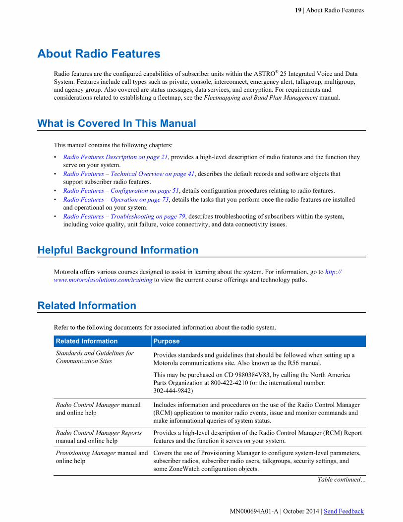
About Radio FeaturesRadio features are the configured capabilities of subscriber units within the ASTRO® 25 Integrated Voice and DataSystem. Features include call types such as private, console, interconnect, emergency alert, talkgroup, multigroup,and agency group. Also covered are status messages, data services, and encryption. For requirements andconsiderations related to establishing a fleetmap, see the Fleetmapping and Band Plan Management manual.
What is Covered In This Manual
This manual contains the following chapters:
• Radio Features Description on page 21, provides a high-level description of radio features and the function theyserve on your system.
• Radio Features – Technical Overview on page 41, describes the default records and software objects thatsupport subscriber radio features.
• Radio Features – Configuration on page 51, details configuration procedures relating to radio features.• Radio Features – Operation on page 73, details the tasks that you perform once the radio features are installed
and operational on your system.• Radio Features – Troubleshooting on page 79, describes troubleshooting of subscribers within the system,
including voice quality, unit failure, voice connectivity, and data connectivity issues.
Helpful Background Information
Motorola offers various courses designed to assist in learning about the system. For information, go to http://www.motorolasolutions.com/training to view the current course offerings and technology paths.
Related Information
Refer to the following documents for associated information about the radio system.
Related Information Purpose
Standards and Guidelines forCommunication Sites
Provides standards and guidelines that should be followed when setting up aMotorola communications site. Also known as the R56 manual.
This may be purchased on CD 9880384V83, by calling the North AmericaParts Organization at 800-422-4210 (or the international number:302-444-9842)
Radio Control Manager manualand online help
Includes information and procedures on the use of the Radio Control Manager(RCM) application to monitor radio events, issue and monitor commands andmake informational queries of system status.
Radio Control Manager Reportsmanual and online help
Provides a high-level description of the Radio Control Manager (RCM) Reportfeatures and the function it serves on your system.
Provisioning Manager manual andonline help
Covers the use of Provisioning Manager to configure system-level parameters,subscriber radios, subscriber radio users, talkgroups, security settings, andsome ZoneWatch configuration objects.
Table continued…
19 | About Radio Features
MN000694A01-A | October 2014 | Send Feedback

Related Information Purpose
Configuration Manager – Conven-tional manual and online help.
Covers the use of the Configuration Manager application to configure conven-tional system parameters for consoles, channels and user objects.
MKM 7000 Console Alias Manag-er manual and online help
Provides information required to install, configure, and operate the optionalMKM 7000 Console Alias Manager (CAM) solution for generating and manag-ing aliases at the console site level.
PremierOne CAD User Guide(PremierOne solution)
Describes how to address ASTRO® radios, how to send text messages, sendand receive queries, and how to use the person location feature from the per-spective of a CAD dispatcher.
PremierOne Mobile User Guide(PremierOne solution)
Describes how to address ASTRO® radios, how to send text messages, sendand receive queries, and how to use the person location feature from the per-spective of a mobile user.
PremierOne Provisioning UserGuide (PremierOne solution)
Describes how to configure ASTRO® radios, messaging, query, and the personlocation feature.
Smart Client User Guide (Premier-One solution)
Describes the Smart Client, an application used to provide text-messaging, ad-dress book, and optionally query functionality for ASTRO® 25 radios.
CPS Online Help Contains the information on how to use the CPS software to program subscrib-er radios.
Motorola GGM 8000 HardwareUser Guide
Contains basic information on the GGM 8000 gateway.
Available on the Motorola Online website (http://businessonline.motoro-la.com). To access the manual, select Resource Center → Product Informa-tion → Manuals → Network Infrastructure → Routers and Gateways.
System Documentation Overview For an overview of the ASTRO® 25 system documentation, open the graphicaluser interface for the ASTRO® 25 system documentation set, at wls.mot.com,select the Master List, and then select the System Documentation Overviewlink. This opens a file that includes:
• ASTRO® 25 system release documentation descriptions• ASTRO® 25 system diagrams
For an additional overview of the system, review the architecture and descrip-tive information in the manuals that apply to your system configuration.
Trunked Data Services This manual describes the implementation and use of trunked data services onASTRO® 25 IV&D systems. It covers the Trunked IV&D, including ClassicData and Enhanced Data, and the High Availability for Trunked IV&D (HAData) feature.
For more details regarding subscriber radios, do one of the following
• See Subscribers Radio Models on page 23.• Contact your Motorola representative• Visit the Motorola website at www.motorolasolutions.com
20 | About Radio Features
Send Feedback | October 2014 | MN000694A01-A
Chapter
1Radio Features Description
This chapter provides a high-level description of radio features and the function they serve on your system.
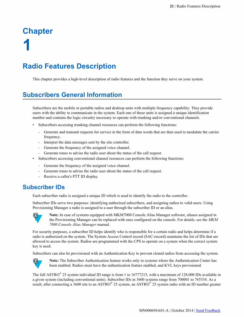
Subscribers General Information
Subscribers are the mobile or portable radios and desktop units with multiple frequency capability. They provideusers with the ability to communicate in the system. Each one of these units is assigned a unique identificationnumber and contains the logic circuitry necessary to operate with trunking and/or conventional channels.
• Subscribers accessing trunking channel resources can perform the following functions:
- Generate and transmit requests for service in the form of data words that are then used to modulate the carrierfrequency.
- Interpret the data messages sent by the site controller.- Generate the frequency of the assigned voice channel.- Generate tones to advise the radio user about the status of the call request.
• Subscribers accessing conventional channel resources can perform the following functions:
- Generate the frequency of the assigned voice channel.- Generate tones to advise the radio user about the status of the call request.- Receive a caller's PTT ID display.
Subscriber IDsEach subscriber radio is assigned a unique ID which is used to identify the radio to the controller.
Subscriber IDs serve two purposes: identifying authorized subscribers, and assigning radios to valid users. UsingProvisioning Manager a radio is assigned to a user through the subscriber ID or an alias.
Note: In case of systems equipped with MKM7000 Console Alias Manager software, aliases assigned inthe Provisioning Manager can be replaced with ones configured on the console. For details, see the MKM7000 Console Alias Manager manual.
For security purposes, a subscriber ID helps identify who is responsible for a certain radio and helps determine if aradio is authorized on the system. The System Access Control record (SAC-record) maintains the list of IDs that areallowed to access the system. Radios are programmed with the CPS to operate on a system when the correct systemkey is used.
Subscribers can also be provisioned with an Authentication Key to prevent cloned radios from accessing the system.
Note: The Subscriber Authentication feature works only in systems where the Authentication Center hasbeen enabled. Radios must have the authentication feature enabled, and KVL keys provisioned.
The full ASTRO® 25 system individual ID range is from 1 to 16777215, with a maximum of 128,000 IDs available ina given system (including conventional units). Subscriber IDs in 3600 systems range from 700001 to 765534. As aresult, after connecting a 3600 site to an ASTRO® 25 system, an ASTRO® 25 system radio with an ID number greater
21 | Radio Features Description
MN000694A01-A | October 2014 | Send Feedback
than 65534 (the leading “7” is omitted) cannot private call a 3600 radio. Also, since it does not fit in the SmartZone®
ID range, its PTT-ID cannot appear on the 3600 radio's display.
MDC1200 channels and ACIM channels configured to be MDC1200 signaling-capable can be associated to aConventional Channel Group configured for either the Standard or Non-Standard MDC ID Range. Channelsconfigured for the Standard MDC ID Range do not support the Group and Wildcard MDC 1200 Addresses. These areIDs starting with E or containing F respectively and are not able to be used by the MCC 7500/7100 console foroutbound signaling as it does not support Group or Wildcard Addressing. Channels configured for the Non-StandardMDC ID Range support Unit IDs starting with E or containing F. The MCC 7500/7100 console treats these IDssimply as additional Unit IDs on the MDC 1200 channels, effectively extending the number of Unit IDs that can beassigned to MDC subscriber radios and MCC consoles. Outbound signaling to Unit IDs on MDC 1200 channels partof a Non-Standard Channel Group is supported by the MCC 7500/7100 console.
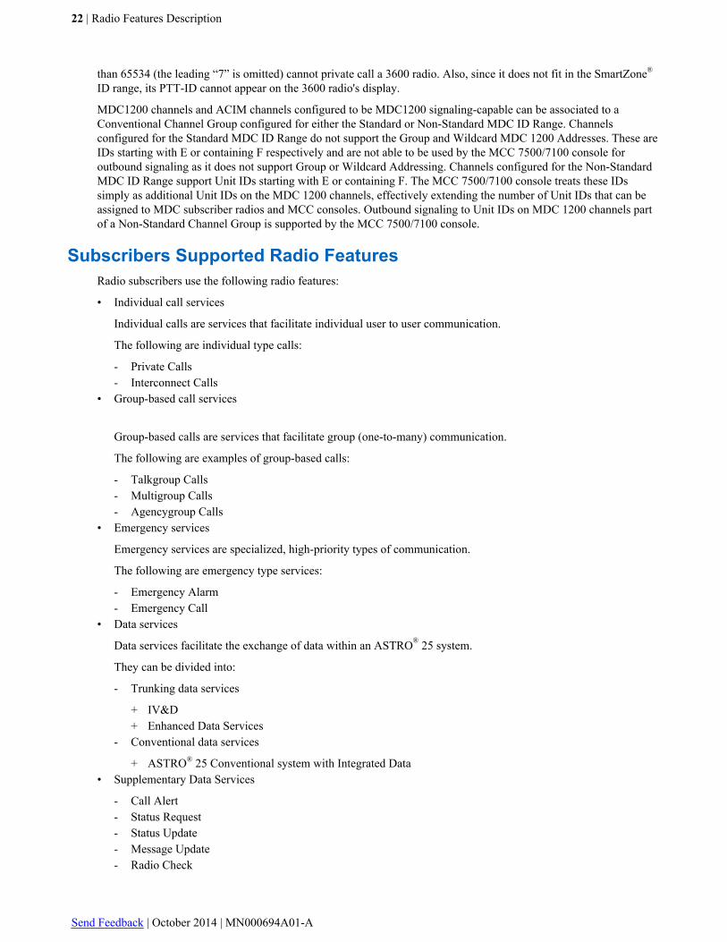
Subscribers Supported Radio FeaturesRadio subscribers use the following radio features:
• Individual call services
Individual calls are services that facilitate individual user to user communication.
The following are individual type calls:
- Private Calls- Interconnect Calls
• Group-based call services
Group-based calls are services that facilitate group (one-to-many) communication.
The following are examples of group-based calls:
- Talkgroup Calls- Multigroup Calls- Agencygroup Calls
• Emergency services
Emergency services are specialized, high-priority types of communication.
The following are emergency type services:
- Emergency Alarm- Emergency Call
• Data services
Data services facilitate the exchange of data within an ASTRO® 25 system.
They can be divided into:
- Trunking data services
+ IV&D+ Enhanced Data Services
- Conventional data services
+ ASTRO® 25 Conventional system with Integrated Data• Supplementary Data Services
- Call Alert- Status Request- Status Update- Message Update- Radio Check
22 | Radio Features Description
Send Feedback | October 2014 | MN000694A01-A

- Radio Enable/Disable- Remote Monitor- Continuous PTT Updating
• Radio security services
Radio security services are the features that allow for secure communication within an ASTRO® 25 system.
The following are subscriber security features:
- Selective Radio Inhibit- Dynamic Regrouping- Encrypted Integrated Data- Subscriber Authentication- Over the Air Re-keying (OTAR)- End-to-End Encryption
• Other services
- ASTRO® 25 system Portable Radio Scan Features- ISSI.1 Interoperability- PS LTE PTT Gateway Site- Talk Around Mode- Failsoft Mode- Outdoor Location- Messaging and Query- Increased Subsite Capability for IP Simulcast Trunking (32 subsite Capacity)- Site Selectable Alerts for Trunking- MDC 1200 Signaling
Subscribers Radio Models
The following tables contain features, encryption types and frequency bands for the mobile and portable subscriberradio and Consolette models available for use on ASTRO® 25 radio systems.
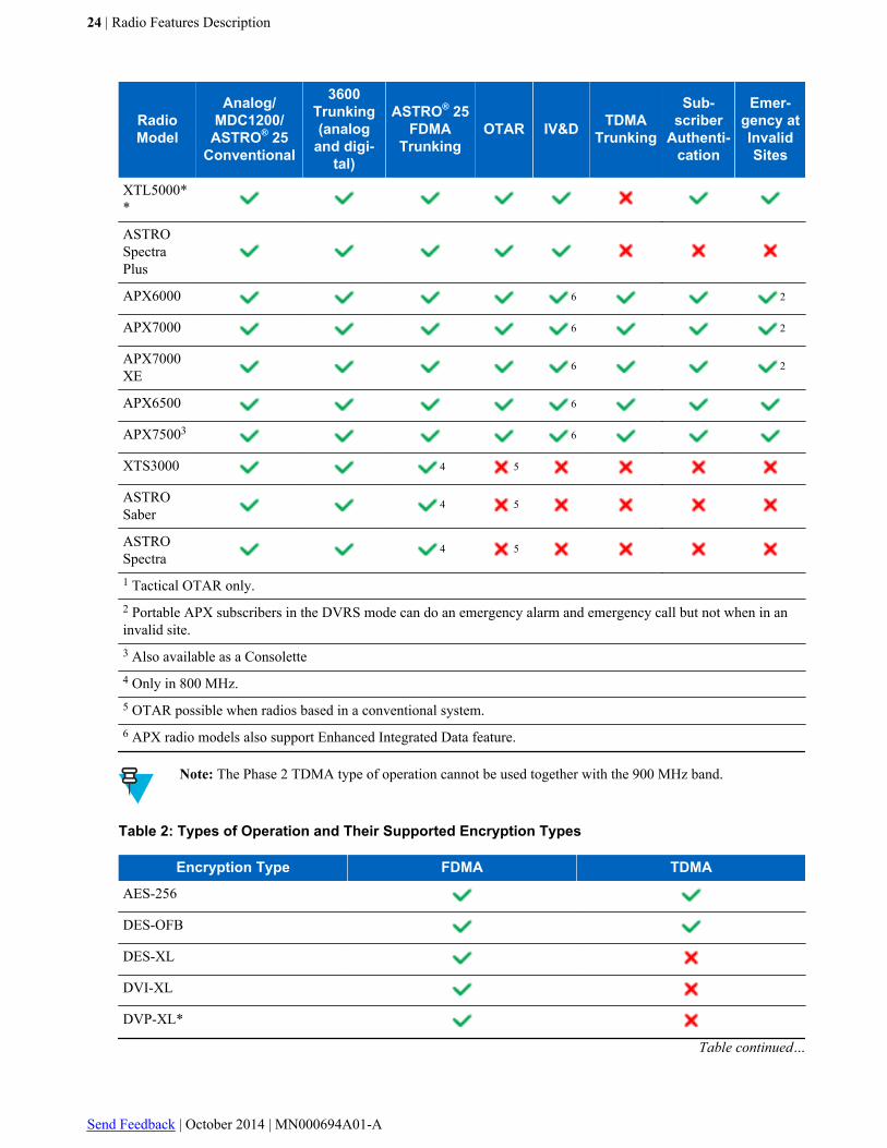
Table 1: Subscriber Models – Supported Features
RadioModel
Analog/MDC1200/
ASTRO® 25Conventional
3600Trunking(analog
and digi-tal)
ASTRO® 25FDMA
TrunkingOTAR IV&D TDMA
Trunking
Sub-scriber
Authenti-cation
Emer-gency atInvalidSites
XTS1500BN
XTS2500BN
1
XTS4000
XTS5000
XTL1500
XTL2500 1
Table continued…
Radio Features Description | 23
MN000694A01-A | October 2014 | Send Feedback
RadioModel
Analog/MDC1200/
ASTRO® 25Conventional
3600Trunking(analog
and digi-tal)
ASTRO® 25FDMA
TrunkingOTAR IV&D TDMA
Trunking
Sub-scriber
Authenti-cation
Emer-gency atInvalidSites
XTL5000**
ASTROSpectraPlus
APX6000 6 2
APX7000 6 2
APX7000XE
6 2
APX6500 6
APX75003 6
XTS3000 4 5
ASTROSaber
4 5
ASTROSpectra
4 5
1 Tactical OTAR only.2 Portable APX subscribers in the DVRS mode can do an emergency alarm and emergency call but not when in aninvalid site.3 Also available as a Consolette4 Only in 800 MHz.5 OTAR possible when radios based in a conventional system.6 APX radio models also support Enhanced Integrated Data feature.
Note: The Phase 2 TDMA type of operation cannot be used together with the 900 MHz band.
Table 2: Types of Operation and Their Supported Encryption Types
Encryption Type FDMA TDMA
AES-256
DES-OFB
DES-XL
DVI-XL
DVP-XL*
Table continued…
24 | Radio Features Description
Send Feedback | October 2014 | MN000694A01-A

Encryption Type FDMA TDMA
ADP
* Even though this encryption type is supported on the APX7000/7500 subscriber models in all modes of operation,it is generally not used, as consoles do not support it.
Table 3: Subscriber Models – Supported Frequency Types
Subscriber Mod-el 700 MHz 800 MHz 900 MHz UHF VHF
APX series
XTL 2500/1500 *
XTL (other models)
XTS 2500/1500 *
XTS (other models)
* Only in:
• Analog Conventional• MDC-1200 Conventional• Analog Operation• P25 Digital Conventional• P25 FDMA Trunking
For more details regarding subscriber radios, contact your Motorola representative or visit the Motorola website atwww.motorolasolutions.com.
Radio System Users
The radio system stores information about users, according to their individual location, and current group affiliation:
• Radio users: personnel using the trunked system are assigned a radio that is active in the system. A radio user isassociated with a specific radio when the radio’s ID is entered into the Provisioning Manager application. A radioalias is name of a radio user assigned to the Radio ID.
• Each console is assigned to a radio ID where each console user can have a radio alias associated with the radio ID.Personnel using the trunked system through a console are assigned a radio ID that is active in the system (nophysical subscriber unit is involved). A console user is associated with a specific radio unit ID when the radio IDis entered into the console user's record in the Provisioning Manager.
ASTRO 25 Portable Radio Signaling Types
The following is a list of signaling types:
• ASTRO® 25 system FDMA trunking• P25 Phase 2 TDMA Trunking• Analog Type II Trunking• ASTRO® Type II Trunking
Radio Features Description | 25
MN000694A01-A | October 2014 | Send Feedback
• ASTRO® P25 Conventional• MDC 1200 Conventional
Conventional Operation
Section Conventional Unit ID on page 43 contains general information on configuring conventional unit IDs.General information on configuring conventional channel groups is listed in section Conventional Channel Group onpage 44 .
For information on configuring conventional sites and channels, see section Conventional Sites and Channels –Configuration on page 56 .
The list of subscriber models supporting conventional operation can be found in section Subscribers Radio Models onpage 23 .
Note: For more details regarding conventional operations, see the Conventional Operations manual.
ASTRO 25 Radio Features
This section provides the information on the following ASTRO® 25 system radio features:
• Call Services on page 26• Enhanced Data Services on page 30• Supplementary Data Services on page 31• Radio Security Services on page 33• Other Services on page 34
Call ServicesMotorola trunked system supports several types of calls. They can be divided into:
• Individual Calls on page 26• Group Calls on page 26
Individual CallsThere are two types of individual calls:
• Private calls (direct calls between two radios, or between a radio and a console operator)
Note: A special type of private call is the console call (direct call between a radio and a consoleoperator).
• Interconnect calls (direct calls between a radio subscriber and a telephone user)
Group CallsThere are three types of group calls:
• Talkgroup calls (described in section Talkgroups on page 27 )
Note: A special type of talkgroup call is the console call (console operator calling all talkgroup users).
• Multigroup calls (described in section Multigroups on page 27 )
26 | Radio Features Description
Send Feedback | October 2014 | MN000694A01-A
• Agencygroup calls (described in section Agencygroups on page 28 )
Access types for all three types of call groups are described in section Talkgroup, Multigroup, and AgencygroupAccess Types on page 28 .
Note: Talkgroups, multigroups and agencygroups in a system supporting Dynamic Dual Mode (DDM)operation can be established as either FDMA-only, TDMA-only, or Dynamic. In systems that supportDDM, trunked TDMA operation supports all of the call types that trunked FDMA operation supports in theTDMA mode. FDMA-only radios or radios at FDMA-only sites can interact with Dynamic Dual Mode(DDM) capable subscribers.
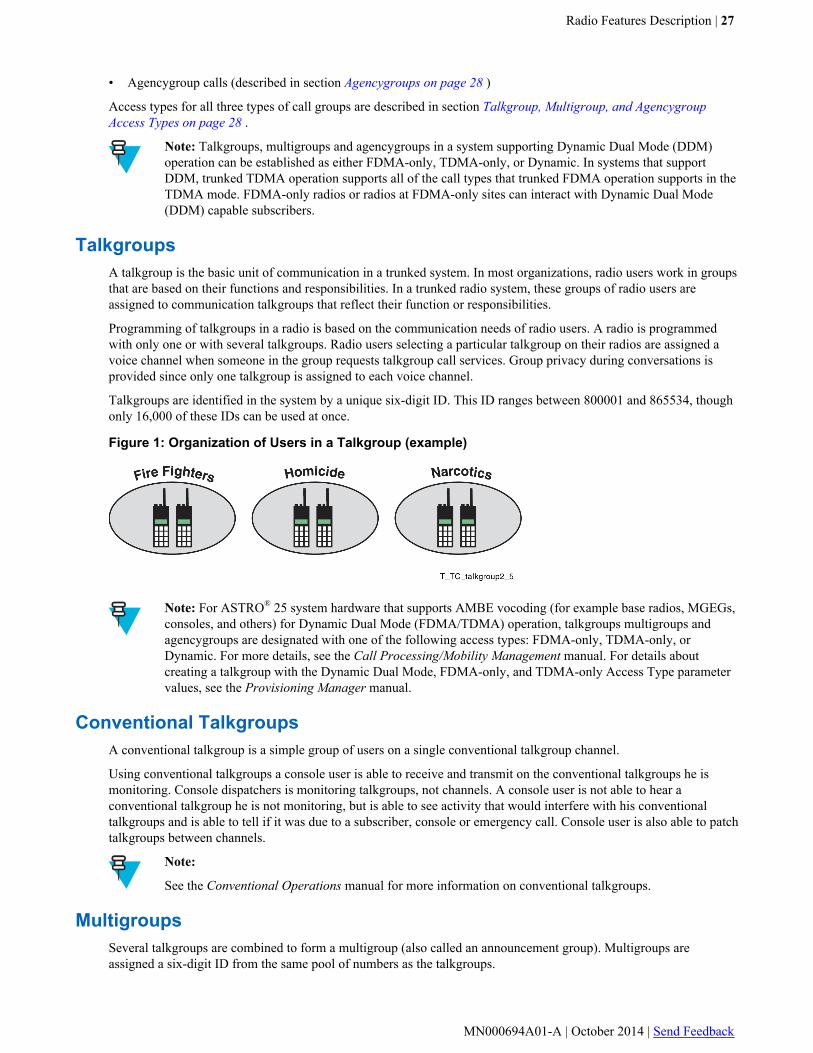
TalkgroupsA talkgroup is the basic unit of communication in a trunked system. In most organizations, radio users work in groupsthat are based on their functions and responsibilities. In a trunked radio system, these groups of radio users areassigned to communication talkgroups that reflect their function or responsibilities.
Programming of talkgroups in a radio is based on the communication needs of radio users. A radio is programmedwith only one or with several talkgroups. Radio users selecting a particular talkgroup on their radios are assigned avoice channel when someone in the group requests talkgroup call services. Group privacy during conversations isprovided since only one talkgroup is assigned to each voice channel.
Talkgroups are identified in the system by a unique six-digit ID. This ID ranges between 800001 and 865534, thoughonly 16,000 of these IDs can be used at once.
Figure 1: Organization of Users in a Talkgroup (example)
Note: For ASTRO® 25 system hardware that supports AMBE vocoding (for example base radios, MGEGs,consoles, and others) for Dynamic Dual Mode (FDMA/TDMA) operation, talkgroups multigroups andagencygroups are designated with one of the following access types: FDMA-only, TDMA-only, orDynamic. For more details, see the Call Processing/Mobility Management manual. For details aboutcreating a talkgroup with the Dynamic Dual Mode, FDMA-only, and TDMA-only Access Type parametervalues, see the Provisioning Manager manual.
Conventional TalkgroupsA conventional talkgroup is a simple group of users on a single conventional talkgroup channel.
Using conventional talkgroups a console user is able to receive and transmit on the conventional talkgroups he ismonitoring. Console dispatchers is monitoring talkgroups, not channels. A console user is not able to hear aconventional talkgroup he is not monitoring, but is able to see activity that would interfere with his conventionaltalkgroups and is able to tell if it was due to a subscriber, console or emergency call. Console user is also able to patchtalkgroups between channels.
Note:
See the Conventional Operations manual for more information on conventional talkgroups.
MultigroupsSeveral talkgroups are combined to form a multigroup (also called an announcement group). Multigroups areassigned a six-digit ID from the same pool of numbers as the talkgroups.
Radio Features Description | 27
MN000694A01-A | October 2014 | Send Feedback

In this example, radio users in the narcotics and homicide talkgroups can hear calls placed to the police multigroup.
Figure 2: Organization of Talkgroups in Multigroups (example)
AgencygroupsSeveral multigroups are combined to form an agencygroup. Agencygroups are assigned a six-digit ID from the samepool of numbers as talkgroups or multigroups.
Figure 3: Organization of Multigroups in Agencygroups (example)
Talkgroup, Multigroup, and Agencygroup Access TypesTalkgroups, multigroups, and agencygroups can be configured as FDMA-only, TDMA-only, or Dynamic. Whensystem elements (subscriber radios, base radios, MGEGs, consoles, and others) support AMBE vocoding of audio,talkgroups, multigroups, and agencygroups configured as TDMA-only or Dynamic can facilitate two voice calls (orslots) within a single 12.5 kHz voice channel. By designating talkgroups, multigroups and agencygroups as eitherFDMA-only or Dynamic, a capable system can dynamically assign channel resources within the system to allowtraditional subscriber radios (IMBE vocoding) to interact with TDMA-capable subscriber radios.
The AMBE+2 enhanced half-rate (EHR) audio vocoding method provides the basis for TDMA to be able to facilitatetwo voice calls within a single 12.5 kHz voice channel. It also improves in-audio quality, making its audioperformance in Enhanced Half Rate mode (TDMA over the air) equivalent to the IMBE full rate (APCO Phase 1)vocoding.
The APX subscriber radios employ AMBE+2 enhanced full rate vocoding for FDMA calls and AMBE+2 enhancedhalf rate vocoding for TDMA calls. The AMBE+2 enhanced full rate (EFR) is fully interoperable and backwards-compatible with the IMBE full-rate vocoder used in FDMA (APCO Phase 1).
The system does not allow an FDMA-only radio to be dynamically regrouped to a TDMA-only talkgroup.
28 | Radio Features Description
Send Feedback | October 2014 | MN000694A01-A
Note: For details about creating a talkgroup with the Dynamic Dual Mode, FDMA-only, and TDMA-onlyAccess Type parameter values, see the Provisioning Manager manual.
Talkgroup Select AssistGeo Select provides the ability to dynamically change a radio’s operating talkgroup based on its current location.
Outdoor location is used to track location of radios, either via a cadence or distance update. MotoMapper applicationcan be used to draw borders on a map that results in a talkgroup change on radios in the “fence”. Upon entering orexiting a geo-fence, radio is issued a dynamic regroup command to change talkgroup. When a fence is drawn, anyradio in the fence is dynamically regrouped to appropriate TG. Radio alerts user of change of talkgroup and loss ofGPS
User is able to create, disable, enable and delete GeoFence boundaries. Boundaries may overlap and are assignedpriorities. Radio’s talkgroup is controlled by the highest priority GeoFence in which the radio is located and is atarget.
Boundaries of the GeoFence are displayed on the MotoMapping Client map. You are able to see which GeoFenceBoundary is controlling a Subscriber’s talkgroup, and also radios not associated with the GeoFence in which they arelocated.
It is indicated on the radio that the radio has been regrouped to a new talkgroup and the current talkgroup selectionhas been changed.
It is achieved by updating radio’s position based location update. Radio sends GPS based on distance traveled.
Emergency ServicesEmergency services are specialized, high-priority types of communication. They can be divided into:
Emergency Call on page 29
Emergency Alarm on page 30
Note: For an ASTRO® 25 system interfacing with an ASTRO® 3.1 system conventional site (A3.1coexistence), Emergency acknowledgment (ACK) and Call Alert ACK may source from any attachedconsole system. This means that it may not be apparent which console may have acknowledged the requestor which console may have sent a Call Alert.
Note: The Emergency at Invalid Sites feature enables subscribers to register at sites they are normally notallowed to access (Site Access Denial). In order for the site to accept them, they need to either be sendingan emergency alert or making an emergency call. When an SU enters the emergency mode at an invalidsite, it sends a mobility message(s), to the infrastructure, indicating its emergency mode. The mobilitymessage(s) are sent to the first “not valid” site with an acceptable RSSI.
Regardless of a subscriber emergency mode, this feature will not work when there is FDMA-TDMAincompatibility between the subscriber or its talkgroup, and the site.
For details, see the Call Processing/Mobility Management manual.
Emergency CallAn emergency call can be either a group call or an announcement call. Emergency call is a group call with the highestqueuing priority. When the system is busy, emergency calls are set up immediately by ruthlessly preempting thelowest priority call in progress. The lowest priority call is dropped and the required resources immediately granted tothe emergency call.
Radio Features Description | 29
MN000694A01-A | October 2014 | Send Feedback
Emergency AlarmEmergency alarm is a data-only signal that alerts a console operator to a subscriber with an emergency condition.Since these messages are sent on the control channel and do not require a voice resource, they are not queued orbusied with an acceptable RSSI. Following the receipt of the registration message with the emergency bit set, the sitewill allow the radio to access the usually invalid site for the duration of the emergency event.
Data ServicesThis section describes the following features:
• Enhanced Data Services on page 30• Conventional Data Services on page 31
Enhanced Data ServicesEnhanced Data is a Motorola proprietary (not P25 standard) inbound-only packet data service optimized forapplications that periodically send short messages from a subscriber or attached device to a host in the CustomerEnterprise Network (CEN). Enhanced Data is only supported on ASTRO® 25 Trunked IV&D systems with GTRseries site equipment and APX subscriber units. Datagrams carried via Enhanced Data must use UDP/IPv4 fornetwork transport between the subscriber or attached device and the CEN. The subscriber uses the Enhanced Dataservice when the following conditions are met:
• The radio has the Enhanced Data option.• Radio is enabled for Enhanced Data in the Provisioning Manager application.• The UDP Destination Port number in an inbound datagram matches one of the Enhanced Data Port numbers in the
subscriber, configured through Customer Programming Software (CPS).• The site includes a channel enabled for Reserved Access capability, which means that the channel supports
Enhanced Data.• Message size does not exceed the maximum packet size allowed for Enhanced Data. If the message is over the
limit, it can be sent via classic, depending on a radio setting.
Neither TCP nor IPv6 are supported for datagram transport. Optionally, either Header Compression (UDP/IP) orIPSec encryption via the Encrypted Integrated Data (EID) feature can be used together with Enhanced Data. AnEnhanced Data message can contain a maximum of 384 bytes of data, including user payload and all headers. Anydata messages larger than this size are sent using Classic Data.
Enhanced Data introduces a new type of data channel to support short, periodic inbound data messages, such as GPSlocation. The Enhanced Data channel is a trunked resource at a Radio Frequency (RF) site and is allocated on firstrequest from an Enhanced Data subscriber, then dynamically based on a periodic evaluation of the Enhanced Dataload at the site. The Enhanced Data channel is based on the timing and signaling characteristics of the Phase 2 TDMAchannel. However, both logical TDMA channels are used in tandem to provide Enhanced Data service. It is notpossible to run Enhanced Data on one logical channel and voice on the other logical channel. Only inbound packetdata messaging is supported. No outbound packet data messaging is supported on Enhanced Data channels. Contextactivation on a Classic Data channel is required before Enhanced Data messaging can be performed.
An inbound datagram is sent using a reservation scheme where the subscriber computes the number of TDMA timeslots required to send the message and makes a request to the infrastructure for the slots. The infrastructure schedulesthe requested slots, and the scheduling is communicated to the subscriber via outbound signaling on the EnhancedData channel. The subscriber then sends its message using the assigned scheduling, and each slot is acknowledged bythe infrastructure over the air. Any slots of data that are not successfully acknowledged are retransmitted by thesubscriber. Retries are performed until the infrastructure indicates the entire message has been successfully receivedor a predefined retry limit has been reached.
The Enhanced Data feature increases the safety of field users, by providing a practical outdoor tracking solution. Thefeature provides each active subscriber with an inbound data service for sending in periodic location and statusupdates. These short messages are used by dispatchers to track the radio users’ status and location on Computer AidedDispatch (CAD) consoles. Enhanced Data ensures a wide-area, mission-critical, portable and mobile coverage and
30 | Radio Features Description
Send Feedback | October 2014 | MN000694A01-A
offers a better utilization of the system resources. Enhanced Data is optimized for variable reporting rates anddesigned to support applications with message profiles similar to GPS, such as ASTRO 25 Advanced MessagingSolution Smart Client.
The Enhanced Data feature can be used by Public Safety agencies, including police, fire, and EMS, as well as Transitagencies and city services, such as snow plow fleets.
Conventional Data ServicesThe ASTRO® 25 Conventional system with Integrated Data feature of the ASTRO® 25 communication systemprovides a wireless extension through the radio communication infrastructure between the data network and mobiledata devices. Data travels between the fixed wireline network and the wireless clients on the Motorola ASTRO® 25system communication network over conventional resources.
This feature supports unicast and group (broadcast) conventional data. Data can be encrypted or secure.
Supplementary Data ServicesThis section describes the following features:
• Call Alert on page 31• Status Request on page 31• Status Update on page 31• Message Update on page 32• Radio Check on page 32• Radio Enable/Disable on page 32• Remote Monitor on page 32• Continuous PTT Updating on page 32
Call AlertThe Call Alert feature provides an authorized caller the ability to send an audible and visual alert signal to asubscriber radio. Call Alert is a function that allows an authorized caller to leave a notification in an unattended radioin order to indicate that a system user wishes to communicate with the user of the alerted radio. The initiator of a CallAlert may be a dispatcher or another subscriber unit user. Because it does not involve voice communication, the callalert is sent over the control channel and therefore use of this feature does not require a voice channel to be available.For details see Using Call Alert on page 76.
Status RequestA console user can send a status request message over the air to the subscriber radio without talking. This eventinforms the console of the subscriber radio’s current operating condition without interrupting normal groupcommunication. (A properly configured radio is required).
Status UpdateThe Status Update feature enables the status of a radio user (for example, en-route, on-scene, on-break, and others) tobe automatically reported to the dispatcher console operator monitoring the channel when the radio user statuschanges. The status is persistent until the radio changes its status.
If a dispatch console goes offline and then back online again, which results in the state of the radio user being lost, thedispatcher can query the radios for their current status. This is useful to keep track of the status of various radio usersto more effectively manage radio system users.
Radio Features Description | 31
MN000694A01-A | October 2014 | Send Feedback

Note: The Status Update signaling feature is supported in site conventional mode; however, if messages ina message set contain aliases for the numeric message or status values, then those alias references are notavailable in the Conventional Site Controller (cannot be referenced from the Zone Controller). In siteconventional mode, the zone controller is unavailable, so the console only receives the Unit ID and numericvalue for the Message or Status information. Aliasing of Unit IDs is not supported in Site ConventionalMode.
Message UpdateMessage Update is a signaling feature that enables subscriber radios to transmit predefined and/or numeric messages.
Note:
Message Update is available only for MDC 1200 conventional and 3600 trunking systems. For P25 9600systems, see section Messaging and Query on page 38.
The Message Update signaling feature is supported in site conventional mode, however, if the messages ina message set contain aliases for the numeric message or status values, then those alias references are notavailable in the Conventional Site Controller (cannot be referenced from the Zone Controller). In siteconventional mode, the zone controller is unavailable so the console only receives the Unit ID and numericvalue for the Message or Status information. Aliasing of Unit IDs is not supported in Site ConventionalMode.
Use of supplementary data messages (non-voice communications from radio users to dispatchers) can reduce voicetraffic on a conventional channel resource. Using data messages reduces loading on the channel to allow more usersto effectively use the channel and to reduce interruptions for other radio users who do not need the information beingsent to the dispatcher.
Radio CheckThe Radio Check feature allows a system operator to "ping" a radio to see if it is turned on and within range of thesystem. There is no audible or visual alert to the radio operator other than a momentary flash of the radio "transmit"indicator.
Radio Enable/DisableRadio Enable/Radio Disable is a signaling feature that allows the console operator to enable or disable a subscriberradio.
Lost or stolen subscriber radios must not be allowed to be used for unauthorized purposes. The radio enable/disablefeature can prevent unauthorized people from listening to or interrupting communications using a lost or stolen radioby the console operator the render the radio inoperable (radio disable). Once the radio is recovered, the consoleoperator can once again enable the radio and return it to normal operation.
Remote MonitorRemote Monitor is a console feature that allows a console position to activate the transmit audio circuitry of thedesired subscriber radio and key its transmitter. This allows a console operator to hear what is going on at thesubscriber end to determine the safety and welfare of a radio user. For more information, see the “Using the RemoteMonitor” section in the “Radio Features – Operation” chapter.
Continuous PTT UpdatingThis feature allows ASTRO® 25 system radios to receive and display the decimal ID of the transmitting radio in thetalkgroup. The ID will display throughout the duration of the call. The Emergency ID display alternates betweendisplaying emergency and flashing the unit ID. The operation is the same with control stations.
32 | Radio Features Description
Send Feedback | October 2014 | MN000694A01-A
Radio Security ServicesUnauthorized personnel can use lost or stolen radios with the proper encryption keys. To prevent misuse, never leaveradios unattended and store them in a secure location when not in use. Plan for quick removal of the encryption keysin a situation when security is compromised. Use the subscriber lock feature to password-protect the radio.
In addition to keeping radios physically secure, Subscriber Lock feature (described in section Subscriber Lock onpage 33 ), selective radio inhibit and dynamic regrouping commands (described in sections Selective Radio Inhibiton page 33 and Dynamic Regrouping on page 33) can increase radio security if a radio is lost or stolen.
Having applied the basic security guidelines, you can also use the following security features:
• Encrypted Integrated Data on page 33• Subscriber Authentication on page 34• Over the Air Re-keying on page 34• End-to-End Encryption on page 34
Subscriber LockWhen not in use, the subscriber can be locked and password-protected so that only the authorized person can use it.
Selective Radio InhibitTo inhibit radios that are lost or stolen, the selective radio inhibit command is used in the Radio Control Manager(RCM) application. It allows you to remotely remove select radio(s) from service.
Security groups established in the Provisioning Manager application manage which user logins have RCM access towhich radios.
Dynamic RegroupingUsing the Radio Control Manager (RCM) application, you can dynamically regroup a radio. The Regroup commandallows you to assign a talkgroup to a radio without adding the talkgroup to the radio's programming. The Regroup andLock command can be used to isolate the radio from all other talkgroups that are programmed into the radio bylocking the radio onto only the dynamically assign talkgroup.
Note: The system does not allow an FDMA-only radio to be dynamically regrouped to a TDMA-onlytalkgroup.
Encrypted Integrated DataThe Encrypted Integrated Data (EID) feature provides data encryption services to ASTRO® 25 system IntegratedVoice and Data (IV&D) IP Bearer services between the Customer Enterprise Network (CEN) and subscriber radios.This encryption service provides data encryption, decryption, and authentication between each EID-enabledsubscriber radio and a new device in the CEN called a PDEG Encryption Unit (PDEG), by using the Internet ProtocolSecurity (IPsec) protocol. The IPsec defines encryption, authentication and key management routines for ensuring theprivacy, integrity and authenticity of data in the system. The encryption algorithm used is Advanced EncryptionStandard (AES). The subscriber radio and PDEG data encryption keys can be centrally managed using a KeyManagement Facility (KMF) server in the CEN.
Using the EID feature, you can secure data sent using ASTRO® 25 system IP bearer service between the CEN andsubscriber radio, including data sent between CEN applications and subscriber radio internal or external applications.Data remains encrypted between the IPsec tunnel endpoint within the subscriber radio and the IPsec tunnel endpointwithin the PDEG located in the CEN.
For more information on the EID encryption, see the Encrypted Integrated Data manual.
Radio Features Description | 33
MN000694A01-A | October 2014 | Send Feedback
Subscriber AuthenticationThe Subscriber Authentication feature has been designed to enhance subscriber access control. Its aim is to preventcloned radios from accessing the ASTRO® 25 trunking system and causing problems such as theft of resources, theftof service, or disruption of operations.
Each subscriber unit is provided with a different authentication key. When it attempts to connect to a site, thefollowing happens:
1 It receives a challenge message and is supposed to give the appropriate response, based on its authentication key.2 The Authentication Center previously contacted the Zone Controller, where keys assigned to subscribers are
stored and – based on this information – the Zone Controller generates a response that will be expected from thesubscriber.
3 In order to learn what the appropriate response is, the site has to contact the Zone Controller. The Zone Controllerforwards the expected response to the site, enabling it to compare the information received from the ZoneController with the information received from the subscriber unit.
4 Depending on the result of this comparison, the subscriber unit is either accepted or rejected at the site.
Note: The Subscriber Authentication feature works only in systems where the Authentication Center hasbeen enabled. The radios need to be preconfigured using the KVL 4000 device, with the authentication keythat is loaded into the Authentication Center.
For the list of subscriber models supporting the Subscriber Authentication feature, see section Subscribers RadioModels on page 23 .
For more information on this feature, see the Radio Authentication manual.
Over the Air Re-keyingFor security purposes, it is possible to reload subscriber encryption keys without the need to physically connect thesubscriber to the Key Variable Loader. The new keys are sent using radio transmission. This is referred to as Over theAir Re-keying (OTAR).
For the list of subscriber models supporting the OTAR feature, see section Subscribers Radio Models on page 23 .
End-to-End EncryptionEnd-to-End Encryption, or Secure Voice, is an overlay service that allows secure communication between MCC 7500Dispatch Consoles and radio units in the field. Encryption/decryption services are provided by the system endpoints:console, logging interface, and field radio units, so communication remains secure between the source and thedestination.
Other ServicesOther available services include:
• ASTRO 25 Portable Radio Scan Features on page 35• ISSI Inter-RF Subsystem Interface on page 35• PS LTE PTT Gateway Site on page 36• Talk Around Mode on page 36• Simulcast Subsystem – Failsoft Mode on page 36• Unified Network Services on page 38• Messaging and Query on page 38• Increased Subsite Capability for IP Simulcast Trunking (32 subsite Capacity) on page 39• Site Selectable Alerts for Trunking on page 39
34 | Radio Features Description
Send Feedback | October 2014 | MN000694A01-A
ASTRO 25 Portable Radio Scan FeaturesA subscriber can be set up to monitor activity on a configurable list of channels. The following are the available radioscan types:
Scan – both priority and non-priority scan
• Conventional scan• Conventional Priority scan• Trunking talkgroup scan• Trunking Priority scan• Mixed Conventional / Talkgroup scan• Multi-System Trunking Scan• Vote Scan• Data Scan
Note: For an agency call and a subscriber radio that is priority scanning, any agencygroup must beaffiliated to a talkgroup which is part of the agencygroup hierarchy.
ISSI Inter-RF Subsystem InterfaceProject 25 standards include guidelines for interoperability between different P25 compliant RF systems. TheMotorola ASTRO® 25 system provides two solutions:
• ISSI.1 (Inter Subsystem Interface) Network Gateway• ISSI 8000 / CSSI 8000 (Inter-RF Subsystem Interface / Console Subsystem Interface)
ISSI.1
The ISSI.1 (Inter SubSystem Interface) Network Gateway feature which provided wireline interoperability betweendisparate APCO Project 25-compliant (P25) trunked networks which by implementing use of the same or differentSystem and Wide Area Communication Network (WACN) IDs. The ISSI.1 Network Gateway was based on softwarerunning on a Sun Netra™ server with the Solaris operating system and Generic Application Server software. WithISSI.1, the ISSI.1 Network Gateway supported up to a maximum of 27 simultaneous trunked calls between systemsand a maximum of 60 interoperability talkgroup pairs to allow agencies to roam and communicate across largercoverage areas, greatly enhancing overall coordination and effectiveness of multi-agency operations.
Note: For more information, see the ISSI .1 Network Gateway manual.
ISSI 8000 / CSSI 8000
The ISSI 8000 / CSSI 8000 feature is the “next generation” of ISSI.1 and will support interoperability betweendisparate APCO Project 25-compliant (P25) systems and consoles to interface with an ASTRO® 25 system. The heartof this feature is the ISGW (Inter-subsystem Gateway) software running on a Linux platform. A distinguishingcharacteristic of the ISSI 8000 / CSSI 8000 solution is the fact that this feature allows foreign subscriber PTT IDs tobe displayed at console operator positions in the ASTRO® 25 system With ISSI 8000, a mobile or portable subscriberradio user can place and receive voice calls across an ISSI network. These mobile or portable subscriber radios maybe home radios operating in the home system, home radios operating in a foreign system, foreign radios operating in ahome system, foreign radios operating in the foreign system.
Note: For more information, see the ISSI 8000 / CSSI 8000 – InterSystem Gateway manual.
Subscriber Radios - Automatic Roaming and Preferred System
Motorola mobile or portable subscriber radios capable of automatically roaming to other systems are configured toidentify preference for a “Preferred System” to accommodate coverage situations where the coverage area of a homesystem and neighboring system overlap. The “Preferred System” operation for Motorola mobile or portable subscriberradios will support fast, automatic roaming to support ISSI. When configured for a “Preferred System”, the Motorola
Radio Features Description | 35
MN000694A01-A | October 2014 | Send Feedback
mobile or portable subscriber radio will prefer one system over another system when two or more systems are withinan acceptable coverage range. Configured with the MultiSystem coverage type, automatic roaming to foreign systemsis supported where control channel frequencies from foreign systems are programmed into the subscriber radiocodeplug. To support affiliation to foreign talkgroups, subscriber radios can add foreign talkgroup/alias information tothe subscriber personality, configured to support alias display for calls from foreign subscribers, and programmed toadd foreign subscriber ID/alias to call list.
Note: For more detailed information regarding mobile or portable subscriber radios, see your Motorolafield representative.
Automatic Roaming is only supported in RF sites supported by G-series equipment (GCP8000 Site Controller, GCM8000 Comparator, GTR 8000 Base Radio). QUANTAR-based RF sites do not support Automatic Roaming.
PS LTE PTT Gateway SiteThe PS LTE PTT Gateway site consists of the PS LTE PTT gateway, site gateway, site switch, and a firewall. Itprovides wireline interoperability between an ASTRO® 25 system and a PS LTE system.
PS LTE PTT Gateway Site – Modes of OperationThe PS LTE PTT Gateway site can provide communication between the ASTRO® 25 system and the PS LTE systemas long as the following conditions are met:
• The PTT Gateway Module and the Site Relay Module are enabled• Connectivity to the ASTRO® 25 system exists and is operational
A PS LTE PTT Gateway site cannot provide communication between the ASTRO® 25 system and the PS LTE systemsites, if one of the following happens:
• The link to Zone Controller is down• One of the devices has been disabled
Talk Around ModeIn a Talk Around mode, a radio transmits (in simplex mode) to other radios that are in a line-of-sight coverage area. Itis used when a trunked radio cannot find a trunked RF site which is operating in either Wide Area, Site Trunking orSite Failsoft mode.
This mode must be pre-configured in the radio, and must be manually selected by the operator.
Simulcast Subsystem – Failsoft ModeThere are two types of Failsoft available depending on the type of site/subsystem:
• Site Subsystem Failsoft is available for both Circuit-based and IP-based Simulcast subsystems.• Local Failsoft is only available for IP Simulcast Subsites which are part of M core or L core system
configurations. Local Failsoft is a configurable item on each base radio.
Note: An ISR site enters an in-cabinet repeat mode for failsoft. A Simulcast or STRV type system entersub-system wide failsoft with repeat happening through comparator voting.
Site Subsystem Failsoftcan be used when a major failure such as the loss of all Site Controllers at an ASTRO® 25 Repeater Site or aSimulcast Subsystem Prime Site occurs. When this type of major failure occurs, the subsystem can no longermaintain a control channel for use by the subscriber radios operating within the site/subsystem. When this happens,the subscriber radios try to locate another control channel at another repeater site or simulcast subsystem. If thesubscriber radios cannot locate another control channel on which to operate and if the following conditions are met,the subscriber radios operate in Site Failsoft:
• One or more channels within the site/subsystem have been configured for Site Failsoft.
36 | Radio Features Description
Send Feedback | October 2014 | MN000694A01-A
• The subscriber radios are configured for Failsoft operation.
With these conditions met, the subscriber radio enter a two-way conventional mode of operation on a given Failsoftchannel. While in Failsoft, subscriber radio is limited to communicating only with other subscriber radio on thesame Failsoft channel. The channel transmits a beep tone used for Failsoft to notify the radio user that thesubscriber radio is operating on a Failsoft channel.
Note: Failsoft call traffic is still being voted and simulcasted by the available channel resources.
The subscriber radios can be configured for the following modes of Failsoft operations:
• Failsoft by last known control channel – all talkgroups at a site/subsystem use the last known control channeltransmit/receive frequency pair in a conventional mode
• Failsoft by Personality – subscriber radio uses a predefined channel transmit/receive frequency pair in aconventional mode for all talkgroups configured under a given personality in the subscriber radio.
• Failsoft by Talkgroup – subscriber radio uses a predefined channel transmit/receive frequency pair in aconventional mode for a specific talkgroup
• Failsoft Disabled – subscriber radio displays an “Out of Range” indication and no site-based RF communicationsare possible
Subscriber radios automatically exit Failsoft operation when a control channel is detected and the subscriber radio hassynchronized with the site/subsystem.
Local Failsoft can be used when a critical failure occurs involving the IP Simulcast Prime Site, or the links betweenthe IP Simulcast Primary Site and an IP Simulcast Subsite are not functioning. Critical failures can be caused byeither of the following:
• The comparators at the Simulcast Prime Site are inoperable• An IP Simulcast Subsite has lost its links to the comparators at the IP Simulcast Prime Site
Under this type of failure, and if one or more of the Multi-Site Base Radio (MsBR) at a subsite have been configuredfor Local Failsoft, the MsBR enters Local Failsoft mode based on its configuration. MsBRs configured for LocalFailsoft transmit a special Failsoft message indicating Local Failsoft.
The timing of the Local Failsoft alarm tone is different than the Site Failsoft beep tone, so that the radio user is able todistinguish between Local Failsoft and Site (subsystem) Failsoft.
The base radio automatically exits Local Failsoft operation, after detecting that the link to the comparator has beenreestablished, or when the Local Failsoft configuration has been disabled on the base radios. The subscriber radiosautomatically exit Failsoft operation when a control channel is detected and subscriber radio has synchronized withthe control channel.
Note: Any channels frequencies in use for Local Failsoft must be disabled at all other subsites, while LocalFailsoft base radios are transmitting to avoid RF interference between the base radios at the differentsubsites. Use caution when configuring MsBRs for Local Failsoft. As the MsBR in Local Failsoft modekey locally on a simulcast frequency, destructive interference occurs on the same channel if other sub-sitesof the simulcast sub-system transmit on the channel and are within the RF coverage range of the MsBR.
Outdoor LocationThe ASTRO® 25 system Outdoor Location solution is a resource tracking solution that uses Global PositioningSystem (GPS) satellites to provide operators with the ability to locate and track vehicles and personnel that operateoutdoors. This can help reduce response time (dispatcher contacts a unit located closest to an emergency). Also,thanks to input sensors and available output options, various everyday tasks of a radio user can be simplified, and thedispatcher provided with immediate feedback on the current situation.
Available radio accessories include:
• GPS Remote Speaker Microphone• Cellocator device
Radio Features Description | 37
MN000694A01-A | October 2014 | Send Feedback
• Trimble Placer Gold Asset Protection Unit (APU)• Trimble Placer Gold APU with Dead Reckoning Unit (DRU)
For detailed information on the Outdoor Location feature, refer to:
• Unified Network Services Feature manual.• Device Configuration and Installation manual in the Unified Network Services documentation set.
Unified Network Services
Unified Network Services (UNS) is a suite of services with a common Application Programming Interface (API) tosupport network functions in ASTRO® 25 systems.
• The UNS Presence Service provides the ability for an application to publish and receive device and user presencedata.
• The UNS Location Service provides the ability for third-party applications to monitor and archive the currentlocation of Global Positioning System (GPS)-based location reporting devices.
UNS is a subcomponent of many ASTRO® 25 system applications, including:
• ASTRO® 25 Outdoor Location Solution• ASTRO® 25 Advanced Messaging Solution (AAMS)
The ASTRO® 25 Outdoor Location solution is a resource tracking solution that uses Global Positioning System (GPS)satellites to provide operators with the ability to locate and track vehicles and personnel that operate outdoors.
Available radio accessories include:
• GPS Remote Speaker Microphone• Cellocator device• Trimble Placer Gold Asset Protection Unit (APU)• Trimble Placer Gold APU with Dead Reckoning Unit (DRU)
The ASTRO Advanced Messaging Solution (AAMS) solution enables text messaging to be sent to/from ASTROsubscribers.
MotoMapping is a mapping application that is used with the UNS Location Service, through which vehicle trackingand personnel location services are delivered in a graphical display.
For detailed information, refer to the following manuals in the UNS documentation set:
• Unified Network Services Feature Manual• UNS Configuration Manager User Guide• ASTRO 25 Outdoor Location Solution Feature Manual• MotoMapping User Guide
Messaging and QueryMessaging and Query is a feature that permits key notifications (for example, dispatch notifications, emergencymessages, and query responses) to be sent to message capable radios such as APX, XTS, and XTL models.
Note: This is an optional feature; available only if preconfigured in both infrastructure and the subscriberunit. This feature is available in P25 9600 trunking and conventional systems.
For more information, see the following manuals:
• PremierOne CAD User Guide• PremierOne Mobile User Guide• PremierOne Provisioning User Guide
38 | Radio Features Description
Send Feedback | October 2014 | MN000694A01-A
Increased Subsite Capability for IP Simulcast Trunking (32 subsiteCapacity)
This feature increased the number of trunking subsites in an ASTRO 25 system from the currently supported 15 IPsimulcast trunking subsites, to 32 IP simulcast trunking subsites to improve Simulcast coverage without adding newfrequencies.
A large number of subscribers are typically served by a Simulcast subsystem and a subsystem-wide control channeloutage could cause them all to scatter at once to neighboring sites. This can be disruptive to the overall system andmust be avoided even in the most basic deployment configurations.
This feature provides subscriber and base station functionality which will minimize the likelihood of widespread radioscatter during transport network failure and recovery. Upon the loss of packets from the prime site, the base stationsends a proprietary control channel message to the subscribers. This message is used primarily to extend the period oftime that a subscriber stays on the active site prior to searching for neighboring sites. If the subscriber finds a controlchannel at the site during this extended period, it will lock onto it and resume normal processing. If no controlchannel is found at the site during this period, the subscriber proceeds with its normal control channel searchsequence which may include scanning for neighboring sites. Note also that this extended search period may be exitedas a result of user initiated actions such as PTT, manual system selection, emergency call, emergency alarm, call alert,etc.
Note: The subscribers need to be upgraded to the latest software release to support this feature.
Site Selectable Alerts for TrunkingThis feature enables alerting all radios at a RF Site via an audible alert that is played periodically over a lengthy timeperiod. The radios also display the CPS preconfigured alert alias with intelligent lighting which corresponds to thealert message.
Site Selectable Alert (SSA) is initiated by a specially provisioned (Supervisor) Subscriber unit registered to a site inthe system. Supervisor subscriber unit signals the desired alert (15 possible alerts) to a target site or sites where thealert is to be broadcast. Targeted sites within the zone broadcast the alert to all subscribers registered to the targetedsite regardless of affiliated talk group or selected supplementary service.
SSA occurs during idle time and mixes with voice when voice is present. Subscriber units monitoring the ControlChannel receive the alert message and begin playing audible alert which corresponds to the alert message atpreconfigured time intervals.
This feature is supported in the following trunking systems:
• ASTRO® 25 system FDMA Trunking• P25 Phase 2 TDMA Trunking
Radio Features Description | 39
MN000694A01-A | October 2014 | Send Feedback

Chapter
2Radio Features – Technical Overview
This chapter describes the default records and software objects that support subscriber radio features.
Default Records
Provisioning Manager contains default records that allow the system to operate when a configuration record does notexist in the database. Normally, system recognition of a subscriber radio attempting to access the system is achievedafter a radio record is configured and established through the Provisionig Manager application.
Default records allow you to do the following:
• Define privileges during system initialization.• Define privileges for default access to the system.
For more information on default records, see:
• Default Access on page 41• Default Record Assignments on page 42• Using Default Radio User and Talkgroup Records on page 77• the Provisioning Manager manual
Default AccessDefault access is a system condition that allows subscriber radios to access the communication system using a defaultconfiguration when no configuration information is established in Provisioning Manager or available from the UserConfiguration Server application (UCS). Under default access, when a subscriber radio attempts to access the system,a default configuration record is automatically assigned to the subscriber radio. This default record provides thesubscriber radio with a predefined set of call services and permissions. Two types of default access parameters areavailable:
• Individual Default Access Permission indicates whether a zone can automatically create configuration records,for the UCS and Provisioning Manager using default configuration settings for new radios (with radio IDs hometo the zone based on submitted home zone map configuration) that contact the system (affiliations). The newconfiguration records appear in the database as ZC$RADIO ID. If the parameter is set to No, then any systemaccess request from a new radio (with radio IDs home to the zone based on submitted home zone mapconfiguration) is rejected and a new radio cannot access the system until a new radio configuration record isestablished manually using Provisioning Manager.
• Talkgroup Default Access Permission indicates whether a zone can create a new talkgroup record in theProvisioning Manager/UCS database using default settings when a radio request is received on a talkgroup notcurrently in the talkgroup database. The new talkgroup records appear in the database as ZC$TALKGROUP ID. Ifthe parameter is set to No, any requests for a new talkgroup are rejected under normal operating conditions andtherefore you cannot create a default talkgroup record.
41 | Radio Features – Technical Overview
MN000694A01-A | October 2014 | Send Feedback
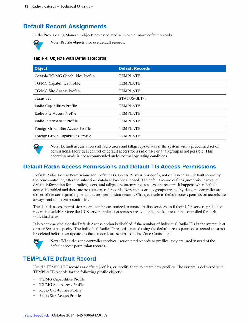
Default Record AssignmentsIn the Provisioning Manager, objects are associated with one or more default records.
Note: Profile objects also use default records.
Table 4: Objects with Default Records
Object Default Records
Console TG/MG Capabilities Profile TEMPLATE
TG/MG Capabilities Profile TEMPLATE
TG/MG Site Access Profile TEMPLATE
Status Set STATUS-SET-1
Radio Capabilities Profile TEMPLATE
Radio Site Access Profile TEMPLATE
Radio Interconnect Profile TEMPLATE
Foreign Group Site Access Profile TEMPLATE
Foreign Group Capabilities Profile TEMPLATE
Note: Default access allows all radio users and talkgroups to access the system with a predefined set ofpermissions. Individual control of default access for a radio user or a talkgroup is not possible. Thisoperating mode is not recommended under normal operating conditions.
Default Radio Access Permissions and Default TG Access PermissionsDefault Radio Access Permissions and Default TG Access Permissions configuration is used as a default record bythe zone controller, after the subscriber database has been loaded. The default record defines guest privileges anddefault information for all radios, users, and talkgroups attempting to access the system. It happens when defaultaccess is enabled and there are no user-entered records. New radios or talkgroups created by the zone controller areclones of the corresponding default access permission records. Changes made to default access permission records arealways sent to the zone controller.
The default access permission record can be customized to control radios services until their UCS server applicationrecord is available. Once the UCS server application records are available, the feature can be controlled for eachindividual user.
It is recommended that the Default Access option is disabled if the number of Individual Radio IDs in the system is ator near System capacity. The Individual Radio ID records created using the default access permission record must notbe deleted before user updates to these records are sent back to the Zone Controller.
Note: When the zone controller receives user-entered records or profiles, they are used instead of thedefault access permission records.
TEMPLATE Default RecordUse the TEMPLATE records as default profiles, or modify them to create new profiles. The system is delivered withTEMPLATE records for the following profile objects:
• TG/MG Capabilities Profile• TG/MG Site Access Profile• Radio Capabilities Profile• Radio Site Access Profile
42 | Radio Features – Technical Overview
Send Feedback | October 2014 | MN000694A01-A

• Radio Interconnect Profile• Foreign Group Site Access Profile• Foreign Group Capabilities Profile
STATUS-SET-1 Default RecordThis record is the default for the Status Set object. It is used by TEMPLATE records. Use this record as a template tocreate new records.
Identification Numbers
ID numbers are one of the key configuration elements that must be entered into the system. Based on the ID numbersthat are entered, the system determines the following:
• Whether or not the individual radio or group is allowed to register at a site• Which call services the individual radio or group can use• What system features the individual radio or group can use• Which zone is responsible for controlling the call (for group calls)
For more information, see:
• Programming ID Numbers on page 43• Conventional Unit ID on page 43• Conventional Channel Group on page 44• Radio Identification on page 44• the Provisioning Manager manual
Programming ID NumbersIndividual and group IDs information from the system fleetmap is programmed into the following areas of the system:
• Individual and talkgroup IDs are entered in the Provisioning Manager.• Each radio is programmed with the system ID, its unique individual ID, and as many talkgroup IDs as needed
(using the applicable programming software).
Note: MCC 7500 consoles are each provisioned with one individual ID.
Conventional Unit IDConventional unit IDs are configured in the Provisioning Manager where the Conventional Unit ID containsinformation about the conventional units within the system. Additionally, you can use the (optional) Console AliasManager to perform some configuration actions.
The conventional unit ID can be assigned to a conventional subscriber or a dispatch console. In the ProvisioningManager Conventional Units are classified as Conventional Voice Unit and Conventional Data Unit. ConsoleApplications maps to these units
Note: Conventional unit ID is entered in hexadecimal number; for channels configured to use standardMDC1200 ranges it is 1–DEEE range, for channels configured to use non-standard ranges it is 1–FFFFrange.
In the (optional) Console Alias Manager, to configure the conventional unit ID, you can use the Unit ID field.Detailed configuration information is included in the MKM 7000 Console Alias Manager manual.
Radio Features – Technical Overview | 43
MN000694A01-A | October 2014 | Send Feedback

Conventional Channel GroupConventional Channels in a zone are logically grouped into conventional channel groups and ranges, which isconvenient in a shared system where agencies/organizations want to use the same ID space. In shared systems withoutconventional channel groups, the conventional unit ID range would need to be partitioned among the agencies/organizations sharing the system. The entire individual ID range can be allocated within each Conventional ChannelGroup, which means that there can be duplicate IDs within the system.
• For every Conventional Channel Group, the console is allocated an individual ID, which is unique within itsassociated Conventional Channel Group.
• Analog channels are automatically assigned a channel group ID of zero (zero cannot be assigned to any othergroup type), and an NM user cannot change this setting.
• The dedicated group for data-capable channels and units is 2001, though non data-capable channels can also usethis group number.
For more details, see the MKM 7000 Console Alias Manager manual (if the MKM 7000 CAM is implemented in yourorganization’s system), and, depending on the system version:
• For M core and L core systems, see the Provisioning Manager manual and online help.• For K core systems, see the Configuration Manager – Conventional manual and online help.
Radio IdentificationThe Radio menu under the Subscriber tab in Provisioning Manager contains IVD Radio and HPD Radio parametersthat contain attributes related to the physical radio unit, such as its unique identity, serial number, RF band, andinterconnect capability. Radio record configuration data is required for each radio that is accessing the system.
A unique radio serial number, radio ID, and an authentication key identify a specific radio and radio user in thesystem. A user alias can be associated with multiple Unit IDs (for example, an officer with multiple radios assigned).In this case the same user alias appears multiple times, each with a different Unit ID.
A console operator position also requires a unique radio identification number and is associated with a talkgroup toaccess audio resources.
Identifying console resources in the same way as radios allows the system to properly identify the source for requestsfor service and to forward information to the correct destinations.
Individual identification numbers used by the system range from 1 to 16,777,215. The IDs are distributed as follows:
• ID 0 is reserved by the system and cannot be assigned to a radio or console resource.• 1 - 16777211 are available for assignment to radios and console resources.• 16777212 is assigned to the RCM as a system wide ID.• 16777213 is reserved by the system for internal use.• 16777214 is reserved by the system for internal use.• 16777215 is reserved for future use.
Some of the radios are data-ready subscriber radios capable of requesting data messaging services across Packet DataChannel (PDCH) resources. Subscriber radios interfacing with mobile data devices are capable of providing data tomobile data applications. These data-ready subscriber radios and mobile data devices are configured and identifiedwith an IP address, as well as other parameters, to support data calls for data communication services. Use theProvisioning Manager to establish the necessary parameters to support data capable subscriber radios.
Radio User
The IVD Radio and HPD Radio objects under the Subscriber category in the Provisioning Manager contain therecords primarily used to identify specific radios on the system their users and capabilities.
See the Provisioning Manager manual for information about configuration of IVD Radio and HPD Radio objects.
44 | Radio Features – Technical Overview
Send Feedback | October 2014 | MN000694A01-A

Radio User Configuration UpdatesDuring system operation, updates are sometimes needed to an existing user configuration information. Changes to aradio user configuration are entered in the Provisioning Manager with the most recent configuration data. Thesechanges can be entered at the user request and distributed to all affected devices in the system. The zone controlleruses this information to populate its Group Home Location Register (GHLR) and Individual Home Location Register(IHLR).
Radio Groups
The system has three types of groups: talkgroup, multigroup, and agencygroup.
• The talkgroup object consists of information that identifies a group of radios that communicate and interacttogether on the system. A talkgroup is designed around a functional group of an organization. For example, aspecial squad inside the state police or a state's Department of Natural Resources (DNR) could each be atalkgroup.
• The multigroup object is used to create records that identify a group of talkgroups that are the target of multigroupannouncements. These records include the same parameters as the talkgroup record plus two parameters specificto the multigroup record. A multigroup lets you combine a number of talkgroups for communication, such asgrouping the state police with the DNR in a multigroup to allow communication between the two organizations.
• The agencygroup object is used to create records that identify a group of multigroups that can communicate witheach other on the system. An agencygroup is one level above the multigroup.
For more information, see:
• Group Calls on page 26• Defining Radio Group IDs on page 45• Creating Talkgroup/Multigroup Profiles on page 61• Creating a Talkgroup, Multigroup, or Agencygroup on page 63• Deleting a Talkgroup, Multigroup, or Agencygroup on page 74• Disabling a Talkgroup, Multigroup, or Agencygroup on page 75• The Provisioning Manager manual
When planning to add a group, consider the possible impact on system resources. Large talkgroups, multigroups, oragencygroups require resources at all sites with affiliated members and may cause busies, especially if all membersare in the same site. In general though, only one channel is needed when all members of a talkgroup are in one site.Consider the system's channel availability. The infrastructure must be in place to support the traffic of added groups.
See the Conventional Operations manual for conventional talkgroups.
Defining Radio Group IDsTalkgroup IDs consist of an eight-digit decimal number beginning with 80000001. Talkgroups, multigroups, andagencygroups are created from the same pool of eight-digit decimal numbers.
The following numbers are reserved:
• 80000000 and 80065535 are reserved for system use.
Note: APCO Project 25 reserves this number, but a Motorola ASTRO® 25 system does not supportsystem-wide calls.
• 80000508– 80000511 are reserved for system operations.
You can create a total of 16,384 talkgroups, multigroups, and agencygroups on a system, using this set of decimalnumbers. The assignable ID numbers can be anywhere in the range from 80000001 to 80065534.
Radio Features – Technical Overview | 45
MN000694A01-A | October 2014 | Send Feedback
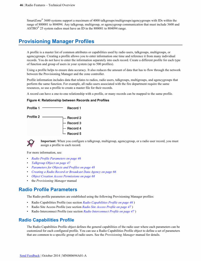
SmartZone® 3600 systems support a maximum of 4000 talkgroups/multigroups/agencygroups with IDs within therange of 800001 to 804094. Any talkgroup, multigroup, or agencygroup communication that must include 3600 andASTRO® 25 system radios must have an ID in the 800001 to 804094 range.
Provisioning Manager Profiles
A profile is a master list of common attributes or capabilities used by radio users, talkgroups, multigroups, oragencygroups. Creating a profile allows you to enter information one time and reference it from many individualrecords. You do not have to enter the information separately into each record. Create a different profile for each typeof function and group of users in your system (up to 500 profiles).
Using a profile helps to ensure data accuracy. It also reduces the amount of data that has to flow through the networkbetween the Provisioning Manager and the zone controller.
Profile information includes data that relates to radios, radio users, talkgroups, multigroups, and agencygroups thatperform the same function. For example, all radio users associated with the fire department require the sameresources, so use a profile to create a master file for their records.
A record can have a one-to-one relationship with a profile, or many records can be mapped to the same profile.
Figure 4: Relationship between Records and Profiles
Important: When you configure a talkgroup, multigroup, agencygroup, or a radio user record, you mustassign a profile to each record.
For more information, see:
• Radio Profile Parameters on page 46• Talkgroup Object on page 47• Parameters for Objects and Profiles on page 48• Creating a Radio Record or Broadcast Data Agency on page 66• Object Creation Access Permissions on page 68• the Provisioning Manager manual
Radio Profile ParametersThe Radio profile parameters are established using the following Provisioning Manager profiles:
• Radio Capabilities Profile (see section Radio Capabilities Profile on page 46 )• Radio Site Access Profile (see section Radio Site Access Profile on page 47 )• Radio Interconnect Profile (see section Radio Interconnect Profile on page 47 )
Radio Capabilities ProfileThe Radio Capabilities Profile object defines the general capabilities of the radio user where each parameters can becustomized for each configured profile. You can use a Radio Capabilities Profile object to define a set of parametersthat are common to a specific group of radio users. See the Provisioning Manager manual for details.
46 | Radio Features – Technical Overview
Send Feedback | October 2014 | MN000694A01-A

Radio Site Access ProfileThe Radio Site Access Profile defines which sites the radio user has access permission for in the system and consistsof privilege information associated with particular sites in the system. Every radio user is assigned a Radio SiteAccess profile.You can use a Radio User Site Access profile record to define the set of parameters that are common toa specific group of radio users. See the Provisioning Manager manual for details.
Radio Interconnect ProfileThe interconnect feature enables landline-to-radio calls and radio-to-landline calls for radio users whose user recordsgrant them permission to make and/or receive the interconnect calls. The Radio Interconnect Profile object defines theinterconnect call capabilities for a radio user. Every radio user is assigned a Radio Interconnect Profile. You can usethe Radio Interconnect Profile record to define the set of parameters that are common to a specific group of radiousers.
The Radio Interconnect Profile object is created with the TEMPLATE default record.
Talkgroup ObjectConsole TG/MG Capabilities Profile on page 48
TG/MG Capabilities Profile on page 48
TG/MG Site Access Profile on page 48
Note: The Multigroup and Agencygroup objects are mapped to the same profiles as the Talkgroup object.See sections Multigroup Parameters on page 48 and Agencygroup Parameters on page 48 for theirrespective parameters.
Talkgroup Object – OverviewThe Talkgroup object consists of the information that identifies a group of radios that communicate and interact witheach other in the system. This group can also be a small subset of a multigroup.
Talkgroup IDs are 8-digit decimal numbers, beginning with 80,000,001. Talkgroups, multigroups, and agencygroupsare created from the same pool of 8-digit decimal numbers. The following numbers are reserved:
Table 5: Reserved Talkgroup IDs
Reserved ID This ID is reserved for...
80,065,535 Addressing all groups in a zone-wide call
80,000,508-80,000,511 System functions
80,000,000 System functions
You can create a total of 16,000 talkgroups and multigroups in the system using this set of decimal numbers. Theycan be anywhere in the range from 80,000,001 to 80,065,534.
Caution: Do not exceed the maximum allowed number of configured talkgroups. This can cause degradedsystem operation or anomalous events.
Caution: System administrators should be certain that talkgroups are only used with sites that are capableof supporting the FDMA or TDMA mode required for that talkgroup. There are no business rules in place,for example, to prevent an operator from configuring a TDMA-only talkgroup to operate on a site withchannels that are only capable of FDMA operation. The same caution applies to the configuration ofFDMA-only individual radios at TDMA-only sites.
Radio Features – Technical Overview | 47
MN000694A01-A | October 2014 | Send Feedback

Console TG/MG Capabilities Profile
A Console Talkgroup/Multigroup (TG/MG) Capabilities Profile is available for setting TG/MG resource capabilities.These profiles allow or limit the accessibility of these resources to specific console features. A Console Talkgroup/Multigroup (TG/MG) Capabilities Profile is also available for setting the Agencygroup capabilities.
TG/MG Capabilities ProfileThe Talkgroup/Multigroup (TG/MG) Capabilities Profile object defines the capabilities for a talkgroup, multigroup,or an agencygroup. Use the TG/MG Capabilities Profile record to define a set of parameters that are common to aspecific talkgroup, multigroup, or agencygroup.
Refer to section TG/MG Capabilities Profile Parameters on page 49 for detailed information on the parameters forthe TG/MG Capabilities Profile.
Note: See the Provisioning Manager manual for creating a talkgroup with the Dynamic Dual Mode,FDMA-only, and TDMA-only Access Type parameter values.
TG/MG Site Access ProfileThe TG/MG Site Access Profile object defines which sites the talkgroup, multigroup, or an agencygroup has accesspermission for in the system. Every talkgroup, multigroup, or agencygroup is assigned a Site Access Profile. Use theTG/MG Site Access Profile record to define a set of sites that are common to a specific talkgroup, multigroup, oragencygroup.
Parameters for Objects and ProfilesThis section provides parameters for objects and profiles.
Multigroup ParametersThe multigroup parameters are as follows:
• Interrupt or Wait Mode
Interrupt mode requires that all radios in the designated talkgroups participate in the call whether the radios aremonitoring the Control Channel or participating in a talkgroup call as receiving radios. A message sent throughthe voice channel, as part of the ASTRO® 25 system embedded signaling, causes the receiving radios to return tothe Control Channel to receive the multigroup's voice channel assignment. The only radios unable to participate ina multigroup call are the currently transmitting ones.
Wait mode allows talkgroup calls in progress to end before a multigroup call begins, the multigroup waits for alltalkgroup members to be available.
• Talkgroup in Multigroup
This parameter is used to enter the list of talkgroups associated with the specified Multigroup ID.
Important: All talkgroups that are assigned to the multigroup must have the same home zone as themultigroup.
Agencygroup ParametersThe agencygroup parameters are as follows:
• Interrupt or Wait Mode
Interrupt mode requires that all radios in the designated multigroups and their talkgroups participate in the call,whether the radios are monitoring the Control Channel, or participating in a multigroup and/or talkgroup call asreceiving radios. A message sent through the voice channel, as part of the ASTRO® 25 system embedded
48 | Radio Features – Technical Overview
Send Feedback | October 2014 | MN000694A01-A
signaling, causes the receiving radios to return to the Control Channel to receive the agencygroup’s voice channelassignment. The only radios unable to participate in an agencygroup call are the currently transmitting ones.
Wait mode allows talkgroup and multigroup calls in progress to end before an agencygroup call begins. Theagencygroup waits for all multigroup members to be available.
• Multigroups in Agencygroup
This parameter is used to enter the list of multigroup associated with the specified agencygroup ID.
Important: All multigroups that are assigned to the agencygroup must have the same home zone as theagencygroup.
TG/MG Capabilities Profile ParametersThe TG/MG Capabilities profile parameters are as follows:
• PTT–ID or Transmission mode operation
Selecting PTT–ID indicates that the system assigns one repeater to the call for the duration of the conversationwithin the parameters of the Message Trunk Timer. Selecting Transmission indicates that the system assigns onerepeater for the duration of a single transmission by one radio.
• Calls Without Console Allowed
Selecting Yes allows the system to process talkgroup calls without a console being involved, if resource failures(for example, MGEG) prevent the console from accessing the system. Selecting No requires any affiliatedconsoles to be part of the call. If a console is affiliated to a talkgroup and resource failures are preventing consolesfrom participating in the call, then the call is not allowed.
• Audio Interrupt Mode: Never, Always, or On Priority
Selecting Never prevents all audio interrupt requests. Selecting Always lets the system automatically grant audiointerrupt requests on the same talkgroup. On Priority determines if the current call is interruptable, based on thesubscriber ID priority. For the interrupt request to be granted, the interrupting radio user must have the same orhigher priority level than the radio user who is currently transmitting.
Each TG/MG Capabilities Profile contains capability parameters that are customized per configured profile. Everytalkgroup and multigroup is assigned a TG/MG Capabilities Profile.
Radio Features – Technical Overview | 49
MN000694A01-A | October 2014 | Send Feedback

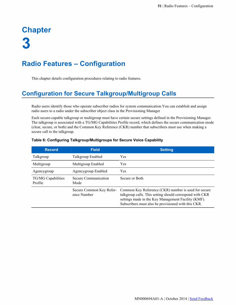
Chapter
3Radio Features – Configuration
This chapter details configuration procedures relating to radio features.
Configuration for Secure Talkgroup/Multigroup Calls
Radio users identify those who operate subscriber radios for system communication.You can establish and assignradio users to a radio under the subscriber object class in the Provisioning Manager
Each secure-capable talkgroup or multigroup must have certain secure settings defined in the Provisioning Manager.The talkgroup is associated with a TG/MG Capabilities Profile record, which defines the secure communication mode(clear, secure, or both) and the Common Key Reference (CKR) number that subscribers must use when making asecure call to the talkgroup.
Table 6: Configuring Talkgroup/Multigroups for Secure Voice Capability
Record Field Setting
Talkgroup Talkgroup Enabled Yes
Multigroup Multigroup Enabled Yes
Agencygroup Agencygroup Enabled Yes
TG/MG CapabilitiesProfile
Secure CommunicationMode
Secure or Both
Secure Common Key Refer-ence Number
Common Key Reference (CKR) number is used for securetalkgroup calls. This setting should correspond with CKRsettings made in the Key Management Facility (KMF).Subscribers must also be provisioned with this CKR.
51 | Radio Features – Configuration
MN000694A01-A | October 2014 | Send Feedback

Figure 5: Secure Settings – TG/MG Capabilities Profile Record
The Secure Communication Mode field has three choices: clear, secure, or both. The following takes place, based onthe selection:
• Talkgroups and announcement groups programmed for clear only are not allowed to initiate a call in secure modeor upgrade to secure while the call is in progress. The zone controller sends a deny Outbound Signaling Packet(OSP) to the requesting subscriber.
• Talkgroups and announcement groups programmed for secure only are not allowed to initiate a call in clear modeor downgrade to clear while the call is in progress. The zone controller sends a deny OSP to the requestingsubscriber.
• Talkgroups and announcement groups programmed for "Both" are allowed to upgrade and downgrade.
The system processes the dynamic regrouping as a talkgroup call. Dynamic regrouping, which is initiated from theRCM, takes individual subscribers that normally do not communicate with each other, and groups them into atalkgroup reserved for specific events. The operation is transparent to the radio user. The subscriber responds to theregrouping command, joins the dynamic talkgroup specified in the OSP, and notifies the user, through a tone and itsdisplay. The communication from that point forward takes place with the dynamic talkgroup and not the talkgroupindicated by the selector position.
Talkgroups designated for dynamic regrouping in the system fleetmap must also be assigned a CKR if it is intendedthat they have secure capability. The talkgroups and their corresponding CKRs are programmed in the ProvisioningManager. Subscribers have no knowledge of the talkgroup ID or CKR assignment until the regrouping OSP isreceived through their Control Channel.
Once active, dynamic regrouping talkgroups follow the same rules for channel grants busies, and denials as all othertalkgroups in the system.
52 | Radio Features – Configuration
Send Feedback | October 2014 | MN000694A01-A
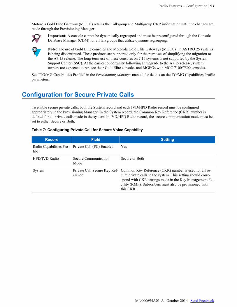
Motorola Gold Elite Gateway (MGEG) retains the Talkgroup and Multigroup CKR information until the changes aremade through the Provisioning Manager.
Important: A console cannot be dynamically regrouped and must be preconfigured through the ConsoleDatabase Manager (CDM) for all talkgroups that utilize dynamic regrouping.
Note: The use of Gold Elite consoles and Motorola Gold Elite Gateways (MGEGs) in ASTRO 25 systemsis being discontinued. These products are supported only for the purposes of simplifying the migration tothe A7.15 release. The long-term use of these consoles on 7.15 systems is not supported by the SystemSupport Center (SSC). At the earliest opportunity following an upgrade to the A7.15 release, systemowners are expected to replace their Gold Elite consoles and MGEGs with MCC 7100/7500 consoles.
See “TG/MG Capabilities Profile” in the Provisioning Manager manual for details on the TG/MG Capabilities Profileparameters.
Configuration for Secure Private Calls
To enable secure private calls, both the System record and each IVD/HPD Radio record must be configuredappropriately in the Provisioning Manager. In the System record, the Common Key Reference (CKR) number isdefined for all private calls made in the system. In IVD/HPD Radio record, the secure communication mode must beset to either Secure or Both.
Table 7: Configuring Private Call for Secure Voice Capability
Record Field Setting
Radio Capabilities Pro-file
Private Call (PC) Enabled Yes
HPD/IVD Radio Secure CommunicationMode
Secure or Both
System Private Call Secure Key Ref-erence
Common Key Reference (CKR) number is used for all se-cure private calls in the system. This setting should corre-spond with CKR settings made in the Key Management Fa-cility (KMF). Subscribers must also be provisioned withthis CKR.
Radio Features – Configuration | 53
MN000694A01-A | October 2014 | Send Feedback
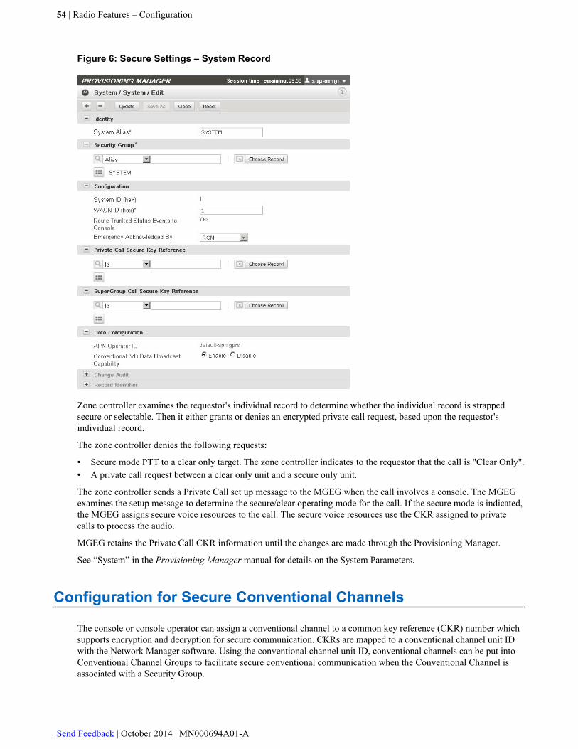
Figure 6: Secure Settings – System Record
Zone controller examines the requestor's individual record to determine whether the individual record is strappedsecure or selectable. Then it either grants or denies an encrypted private call request, based upon the requestor'sindividual record.
The zone controller denies the following requests:
• Secure mode PTT to a clear only target. The zone controller indicates to the requestor that the call is "Clear Only".• A private call request between a clear only unit and a secure only unit.
The zone controller sends a Private Call set up message to the MGEG when the call involves a console. The MGEGexamines the setup message to determine the secure/clear operating mode for the call. If the secure mode is indicated,the MGEG assigns secure voice resources to the call. The secure voice resources use the CKR assigned to privatecalls to process the audio.
MGEG retains the Private Call CKR information until the changes are made through the Provisioning Manager.
See “System” in the Provisioning Manager manual for details on the System Parameters.
Configuration for Secure Conventional Channels
The console or console operator can assign a conventional channel to a common key reference (CKR) number whichsupports encryption and decryption for secure communication. CKRs are mapped to a conventional channel unit IDwith the Network Manager software. Using the conventional channel unit ID, conventional channels can be put intoConventional Channel Groups to facilitate secure conventional communication when the Conventional Channel isassociated with a Security Group.
54 | Radio Features – Configuration
Send Feedback | October 2014 | MN000694A01-A
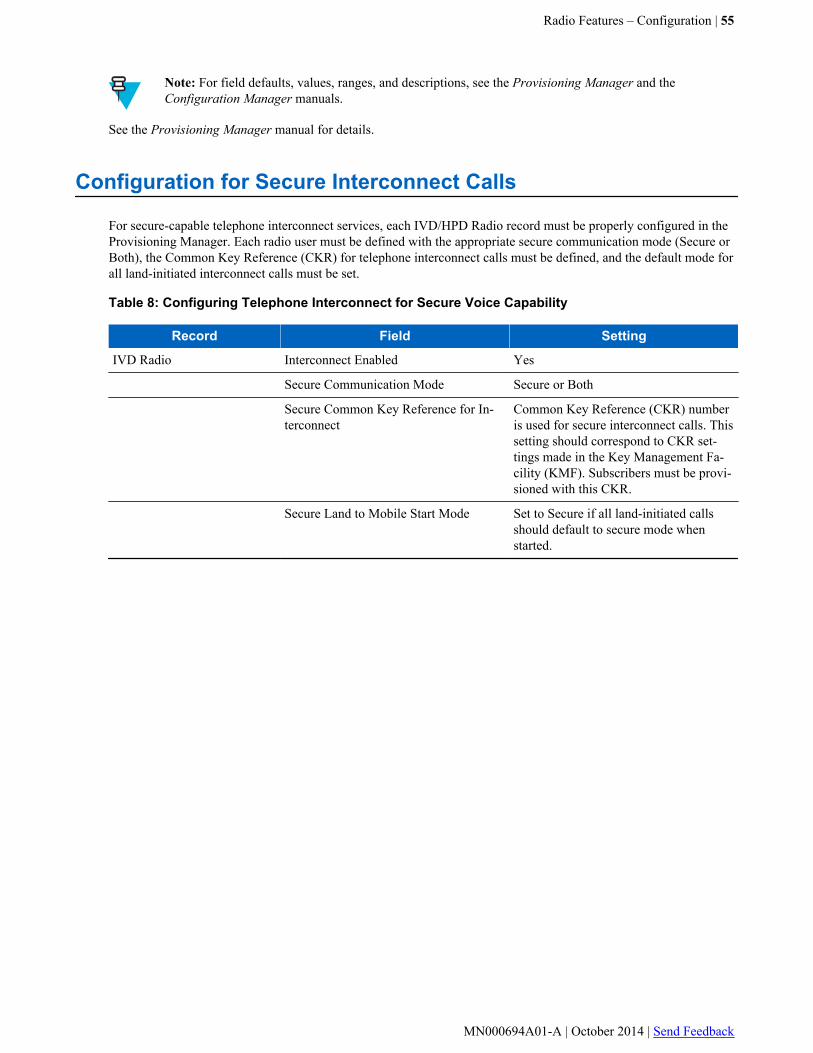
Note: For field defaults, values, ranges, and descriptions, see the Provisioning Manager and theConfiguration Manager manuals.
See the Provisioning Manager manual for details.
Configuration for Secure Interconnect Calls
For secure-capable telephone interconnect services, each IVD/HPD Radio record must be properly configured in theProvisioning Manager. Each radio user must be defined with the appropriate secure communication mode (Secure orBoth), the Common Key Reference (CKR) for telephone interconnect calls must be defined, and the default mode forall land-initiated interconnect calls must be set.
Table 8: Configuring Telephone Interconnect for Secure Voice Capability
Record Field Setting
IVD Radio Interconnect Enabled Yes
Secure Communication Mode Secure or Both
Secure Common Key Reference for In-terconnect
Common Key Reference (CKR) numberis used for secure interconnect calls. Thissetting should correspond to CKR set-tings made in the Key Management Fa-cility (KMF). Subscribers must be provi-sioned with this CKR.
Secure Land to Mobile Start Mode Set to Secure if all land-initiated callsshould default to secure mode whenstarted.
Radio Features – Configuration | 55
MN000694A01-A | October 2014 | Send Feedback
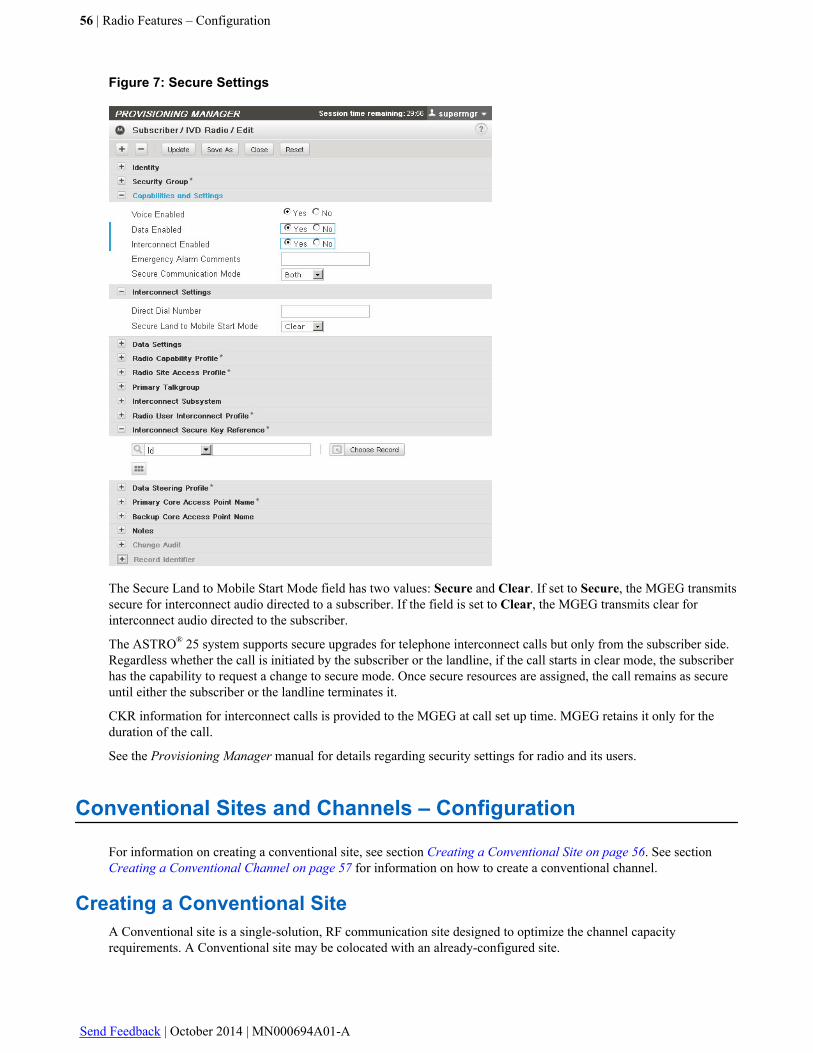
Figure 7: Secure Settings
The Secure Land to Mobile Start Mode field has two values: Secure and Clear. If set to Secure, the MGEG transmitssecure for interconnect audio directed to a subscriber. If the field is set to Clear, the MGEG transmits clear forinterconnect audio directed to the subscriber.
The ASTRO® 25 system supports secure upgrades for telephone interconnect calls but only from the subscriber side.Regardless whether the call is initiated by the subscriber or the landline, if the call starts in clear mode, the subscriberhas the capability to request a change to secure mode. Once secure resources are assigned, the call remains as secureuntil either the subscriber or the landline terminates it.
CKR information for interconnect calls is provided to the MGEG at call set up time. MGEG retains it only for theduration of the call.
See the Provisioning Manager manual for details regarding security settings for radio and its users.
Conventional Sites and Channels – Configuration
For information on creating a conventional site, see section Creating a Conventional Site on page 56. See section Creating a Conventional Channel on page 57 for information on how to create a conventional channel.
Creating a Conventional SiteA Conventional site is a single-solution, RF communication site designed to optimize the channel capacityrequirements. A Conventional site may be colocated with an already-configured site.
56 | Radio Features – Configuration
Send Feedback | October 2014 | MN000694A01-A
The Conventional Site object contains conventional subsystem information for CCGW. Use the parent ConventionalSite to configure CCGW at a conventional subsystem.
The CCGW and CCGW-HD objects represent the Conventional Channel Gateway which controls the Conventionalsite channels. Only one CCGW can be associated with a Conventional site
Note: Depending on the system version, for detailed configuration procedures, refer to:
• For M core and L core systems: see the Provisioning Manager manual and online help.• For K core systems, see the Configuration Manager – Conventional manual and online help.
Creating a Conventional ChannelCreating an Analog Conventional Channel on page 57
Creating a Digital Conventional Channel on page 57
Creating a Conventional Talkgroup Channel on page 57
Creating a Conventional Mixed Mode Channel on page 57
Creating an MDC 1200 Conventional Channel on page 58
Creating an ACIM Conventional Channel on page 58
Important: It is advised that you follow the given sequence of the procedures while creating your records.
Creating an Analog Conventional ChannelThe channel record sets the parameters for the channel operations at the site. The channel record represents the actualoperational parameters of the base radio. .
Note: Depending on the system version, for detailed configuration procedures, refer to:
• For M core and L core systems: see the Provisioning Manager manual and online help.• For K core systems, see the Configuration Manager – Conventional manual and online help.
Creating a Digital Conventional ChannelThe channel record sets the parameters for the channel operations at the site. The channel record represents the actualoperational parameters of the base radio.
Note: Depending on the system version, for detailed configuration procedures, refer to:
• For M core and L core systems: see the Provisioning Manager manual and online help.• For K core systems, see the Configuration Manager – Conventional manual and online help.
Creating a Conventional Talkgroup ChannelThe channel record sets the parameters for the channel operations at the site. The channel record represents the actualoperational parameters of the base radio.
Note: Depending on the system version, for detailed configuration procedures, refer to:
• For M core and L core systems: see the Provisioning Manager manual and online help.
Creating a Conventional Mixed Mode ChannelThe Conventional Mixed Mode Channel is a combination of Analog and Digital channels. The channel record sets theparameters for the channel operations at the site. The channel record represents the actual operational parameters ofthe base radio. The CCGW can control as many as 4 channels.
Radio Features – Configuration | 57
MN000694A01-A | October 2014 | Send Feedback
Important: The Conventional Mixed Mode Channel is only available for the Combination (GGM 8000)sites. See the System Gateways – GGM 8000 manual, for more information on GGM 8000.
Note: Depending on the system version, for detailed configuration procedures, refer to:
• For M core and L core systems, see the Provisioning Manager manual and online help.• For K core systems, see the Configuration Manager – Conventional manual and online help.
Creating an MDC 1200 Conventional ChannelThe channel record sets the parameters for the channel operations at the site. The channel record represents the actualoperational parameters of the base radio.
Note: Depending on the system version, for detailed configuration procedures, refer to:
• For M core and L core systems, see the Provisioning Manager manual and online help.• For K core systems, see the Configuration Manager – Conventional manual and online help.
Creating an ACIM Conventional ChannelThe ACIM channel is used to enable the exchange of control information with a Motorola Consolette. The channel isconfigurable as an ACIM channel with an option for MDC-1200 operation.
Important: ACIM conventional channels are disallowed in certain groups.
Note: Depending on the system version, for detailed configuration procedures, refer to:
• For M core and L core systems, see the Provisioning Manager manual and online help.• For K core systems, see the Configuration Manager – Conventional manual and online help.
Consolette – ConfigurationThe APX Consolette is offered in two configurations:
• L999AA, with a full featured front panel containing an O5 control head, a numeric keypad, an auxiliary displayfor Clock and VU Meter functionality.
• L998AA, with a limited front panel containing only the auxiliary display for Clock and VU Meter functionality.
Both of these configurations provide TRC, ACIM, and E&M remote control operation.
Additionally, there is an orderable option, GA00469AA – Extended Dispatch Functionality, that enables advancedfunctionality through the ACIM interface on ASTRO® P25 and MDC Conventional channels.
A list of advanced functionalities supported by the Consolette can be found in the ACIM Channel Features section ofthe Conventional Operations manual.
For more information, refer to the APX Consolette Detail Service Manual (68009482001).
Radio and Radio User Configuration
Radio and radio user configuration information for call processing support identifies individuals and talkgroups thatuse the system and identifies the services the system must provide to those individuals or talkgroups. Configurationinformation is established in the following places:
• Provisioning Manager – Within Provisioning Manager records are built for radios, radio users, talkgroups, multi-groups and agency-groups with parameters that affect the operations of all radios in the system, including siteaccess denial.
58 | Radio Features – Configuration
Send Feedback | October 2014 | MN000694A01-A

• MKM 7000 Console Alias Manager application - Some of radio and radio user configuration (console alias)information is also entered using the MKM 7000 Console Alias Manager application if this feature is implementedin your system. For more details, see the MKM 7000 Console Alias Manager manual and online help.
• Subscriber Radio Programming – Subscriber radios are programmed using their specific programmingsoftware.
Radio and radio user configuration information is divided into four parts:
• Home Zone assignment for individual and talkgroup IDs• Identification numbers and aliases for individuals and talkgroups• Call services and system features allowed for an individual or talkgroup• Valid site settings for each individual and talkgroup
Radio and radio user configuration information is referenced by the system each time a radio attempts to register to asite and/or affiliate with a talkgroup.
Important: Configuration information must be consistent when programming the Provisioning Managerapplication, radios, and consoles.
Configuring UsersThe Provisioning Manager and Unified Network Configurator (UNC) applications establish configuration informationfor users. Each user record is assigned various configuration parameters that allow it to be identified and operatethroughout the system. The configuration parameters determine the system services available to each user.
Process OverviewThis process outlines the overall steps needed to add users to the system.
Process:
1 Organize configuration information.2 Use the IVD/HPD Radio objects (in the Provisioning Manager) to enter and maintain the following:
• radio and infrastructure records• information about the user of a radio
Trunking Radio Features – Configuration OrderConfiguration information is entered during the initial phase of system operation and updated as the users andcapabilities of the system change.
The following sequence is recommended when initially entering subscriber data in subscriber records in ProvisioningManager:
Table 9: Trunking Radio Features – Configuration Order
Configuration Predecessor
1 Home Zone Mapping None
4 Talkgroup/Multigroup (TG/MG) Capabili-ties Profile
None
5 TG/MG Site Access Profile None
6 Status Set None
7 Radio Capabilities Profile Status Set
8 Radio Site Access Profile NoneTable continued…
Radio Features – Configuration | 59
MN000694A01-A | October 2014 | Send Feedback
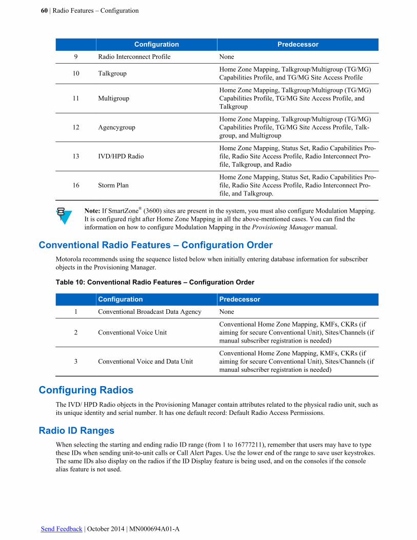
Configuration Predecessor
9 Radio Interconnect Profile None
10 Talkgroup Home Zone Mapping, Talkgroup/Multigroup (TG/MG)Capabilities Profile, and TG/MG Site Access Profile
11 MultigroupHome Zone Mapping, Talkgroup/Multigroup (TG/MG)Capabilities Profile, TG/MG Site Access Profile, andTalkgroup
12 AgencygroupHome Zone Mapping, Talkgroup/Multigroup (TG/MG)Capabilities Profile, TG/MG Site Access Profile, Talk-group, and Multigroup
13 IVD/HPD RadioHome Zone Mapping, Status Set, Radio Capabilities Pro-file, Radio Site Access Profile, Radio Interconnect Pro-file, Talkgroup, and Radio
16 Storm PlanHome Zone Mapping, Status Set, Radio Capabilities Pro-file, Radio Site Access Profile, Radio Interconnect Pro-file, and Talkgroup.
Note: If SmartZone® (3600) sites are present in the system, you must also configure Modulation Mapping.It is configured right after Home Zone Mapping in all the above-mentioned cases. You can find theinformation on how to configure Modulation Mapping in the Provisioning Manager manual.
Conventional Radio Features – Configuration OrderMotorola recommends using the sequence listed below when initially entering database information for subscriberobjects in the Provisioning Manager.
Table 10: Conventional Radio Features – Configuration Order
Configuration Predecessor
1 Conventional Broadcast Data Agency None
2 Conventional Voice UnitConventional Home Zone Mapping, KMFs, CKRs (ifaiming for secure Conventional Unit), Sites/Channels (ifmanual subscriber registration is needed)
3 Conventional Voice and Data UnitConventional Home Zone Mapping, KMFs, CKRs (ifaiming for secure Conventional Unit), Sites/Channels (ifmanual subscriber registration is needed)
Configuring RadiosThe IVD/ HPD Radio objects in the Provisioning Manager contain attributes related to the physical radio unit, such asits unique identity and serial number. It has one default record: Default Radio Access Permissions.
Radio ID RangesWhen selecting the starting and ending radio ID range (from 1 to 16777211), remember that users may have to typethese IDs when sending unit-to-unit calls or Call Alert Pages. Use the lower end of the range to save user keystrokes.The same IDs also display on the radios if the ID Display feature is being used, and on the consoles if the consolealias feature is not used.
60 | Radio Features – Configuration
Send Feedback | October 2014 | MN000694A01-A
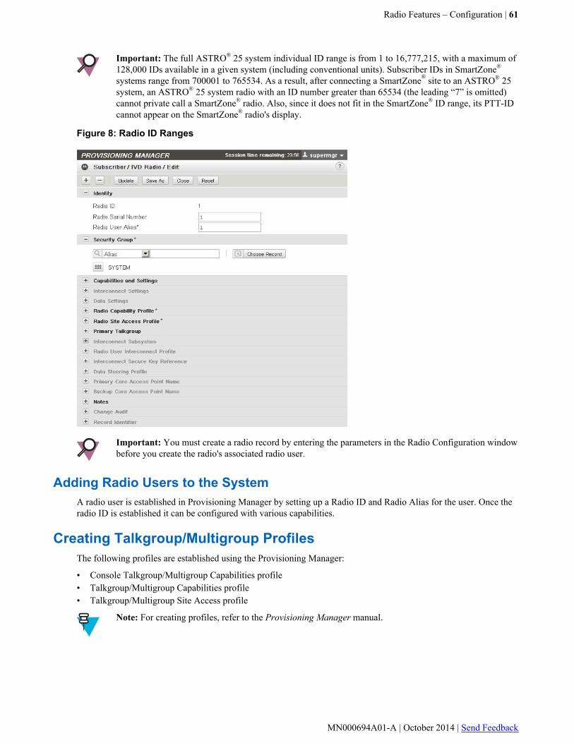
Important: The full ASTRO® 25 system individual ID range is from 1 to 16,777,215, with a maximum of128,000 IDs available in a given system (including conventional units). Subscriber IDs in SmartZone®
systems range from 700001 to 765534. As a result, after connecting a SmartZone® site to an ASTRO® 25system, an ASTRO® 25 system radio with an ID number greater than 65534 (the leading “7” is omitted)cannot private call a SmartZone® radio. Also, since it does not fit in the SmartZone® ID range, its PTT-IDcannot appear on the SmartZone® radio's display.
Figure 8: Radio ID Ranges
Important: You must create a radio record by entering the parameters in the Radio Configuration windowbefore you create the radio's associated radio user.
Adding Radio Users to the SystemA radio user is established in Provisioning Manager by setting up a Radio ID and Radio Alias for the user. Once theradio ID is established it can be configured with various capabilities.
Creating Talkgroup/Multigroup ProfilesThe following profiles are established using the Provisioning Manager:
• Console Talkgroup/Multigroup Capabilities profile• Talkgroup/Multigroup Capabilities profile• Talkgroup/Multigroup Site Access profile
Note: For creating profiles, refer to the Provisioning Manager manual.
Radio Features – Configuration | 61
MN000694A01-A | October 2014 | Send Feedback
Creating a Status SetThe Status Set profile adds up to 16 preconfigured statuses, so that radio users can signal their current status to theRadio Configuration Manager (RCM) by pressing one of the status buttons on the radio. When a radio user sends astatus, it is displayed in the RCM Status Events monitor pane where the RCM user can respond to it. This status istransmitted on the Control Channel to save voice channel resources.
Important: A status set cannot be deleted or renamed once it is added to the system.
Note: The RCM does not display P25 conventional and MDC1200 conventional statuses.
The Status Set profile record consists of two tabs: Basic and Configuration.
Note: Depending on the system version, for detailed configuration procedures, refer to:
• For M core and L core systems, see the Provisioning Manager manual and online help.• For K core systems, see the Configuration Manager – Conventional manual and online help.
Creating a Message SetThe Message Set profile adds up to 16 pre-configured messages so that radio users can signal their current state to theRadio Configuration Manager (RCM) by pressing one of the message buttons on the radio. When a radio user sends amessage, it is displayed in the RCM Status Events monitor pane where the RCM user can respond to it. This messageis transmitted on the control channel to save voice channel resources. Both, the MCC 7500 and the RCM can displaythe Message Set.
The Message Set Profile record consists of two tabs: Basic and Configuration.
Important: A Message Set cannot be deleted once it has been assigned to a Conventional Unit.The defaultMESSAGE_SET-1 cannot be deleted.
Note: The RCM does not display P25 conventional and MDC1200 conventional messages.
Note: Depending on the system version, for detailed configuration procedures, refer to:
• For M core and L core systems, see the Provisioning Manager manual and online help.• For K core systems, see the Configuration Manager – Conventional manual and online help.
Creating Radio User ProfilesThe Radio User Capabilities Profile record defines the common capabilities of the radio user and consists of privilegeinformation associated with particular radio users in the system. This record consists of two tabs, Basic andConfiguration.
The following Radio Profiles are established using the Provisioning Manager:
• Radio Capabilities Profile – this record defines a list of sites that the radio user can access in the system andcontains information about the site at which the radio is valid.
• Radio Site Access Profile – this record defines a list of sites that the radio user can access in the system andcontains information about the site at which the radio is valid.
• Radio Interconnect Profile – the Radio Interconnect Profile record defines the telephone interconnectcapabilities of the radio user.
Note: For creating radio profiles, refer to the Provisioning Manager manual.
62 | Radio Features – Configuration
Send Feedback | October 2014 | MN000694A01-A
Submitting the Home Zone MapThere can be several maps defined in the system, however, only one of them can be active at a time. Home Zone MapSubmission is a process of sending an active map to all initialized devices in the system.
Note: Submitting the home zone map does not activate the map. You need to activate the map manually.For details, refer to the Unified Network Configurator manual. The active map cannot be modified. Ifchanges to the home zone map are required, the new map needs to be submitted.
Note: You cannot modify the active map. If changes to the home zone map are required, the new mapneeds to be submitted.
Note: For detailed configuration procedures, refer to the Provisioning Manager manual and online help.
Creating a Talkgroup, Multigroup, or AgencygroupThe talkgroup object consists of the information identifying a group of radios that communicate and interact togetheron the system. This group can also be a part of a multigroup. The highest level is called the agencygroup and iscomposed of a set of multigroups.
• There can be up to 255 talkgroups in a multigroup.• There can be up to 16 multigroups in an agencygroup.• There can be up to 16 agencygroups on the system.
Defining Talkgroup IDsTalkgroup IDs are 8-digit decimal numbers beginning with 80000000. Talkgroups and multigroups are created fromthe same pool of 8-digit decimal numbers. You can create a total of 16,384 talkgroups and multigroups on a systemusing this set of decimal numbers. They can be anywhere in the range from 80000001 to 80065534.
The following numbers are reserved:
• 80000000 is reserved for system use.
• 80065535 is reserved for addressing all groups in a zone-wide call.
Note: APCO Project 25 reserves this number, but a Motorola system does not support system-widecalls.
The system has three types of groups: talkgroup, multigroup, and agencygroup. A talkgroup is usually designedaround a functional group or an organization. For example, a special squad inside the state police or a state'sDepartment of Natural Resources (DNR) could each be a talkgroup. A multigroup lets you combine a number oftalkgroups for communication, such as grouping the state police with the DNR in a multigroup to allowcommunication between the two organizations. Above that is an agencygroup which is composed of a set ofmultigroups.
When planning to add a group, you must consider the effects it has on system resources. Large talkgroups,multigroups, and agencygroups require resources at all sites with affiliated members and could cause busies,especially if all members are in the same site. Usually only one channel is needed when all members of a talkgroupare in one site. Consider the system's channel availability. The infrastructure must be in place to support the traffic ofadded groups.
Talkgroup RangesWhen adding a talkgroup, consider the normal roaming area of the talkgroup members. Assign the talkgroup's homezone as the zone where the majority of the members spend most of their time. All talkgroups in a multigroup mustshare the same home zone as the multigroup.
Radio Features – Configuration | 63
MN000694A01-A | October 2014 | Send Feedback
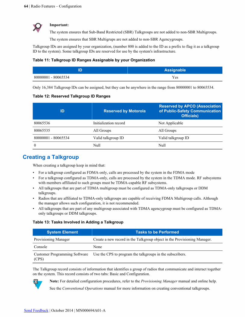
Important:
The system ensures that Sub-Band Restricted (SBR) Talkgroups are not added to non-SBR Multigroups.
The system ensures that SBR Multigrups are not added to non-SBR Agencygroups.
Talkgroup IDs are assigned by your organization, (number 800 is added to the ID as a prefix to flag it as a talkgroupID to the system). Some talkgroup IDs are reserved for use by the system's infrastructure.
Table 11: Talkgroup ID Ranges Assignable by your Organization
ID Assignable
80000001 - 80065534 Yes
Only 16,384 Talkgroup IDs can be assigned, but they can be anywhere in the range from 80000001 to 80065534.
Table 12: Reserved Talkgroup ID Ranges
ID Reserved by MotorolaReserved by APCO (Associationof Public-Safety Communication
Officials)
80065536 Initialization record Not Applicable
80065535 All Groups All Groups
80000001 - 80065534 Valid talkgroup ID Valid talkgroup ID
0 Null Null
Creating a TalkgroupWhen creating a talkgroup keep in mind that:
• For a talkgroup configured as FDMA-only, calls are processed by the system in the FDMA mode• For a talkgroup configured as TDMA-only, calls are processed by the system in the TDMA mode. RF subsystems
with members affiliated to such groups must be TDMA-capable RF subsystems.• All talkgroups that are part of TDMA multigroup must be configured as TDMA-only talkgroups or DDM
talkgroups.• Radios that are affiliated to TDMA-only talkgroups are capable of receiving FDMA Multigroup calls. Although
the manager allows such configuration, it is not recommended.• All talkgroups that are part of any multigroup associated with TDMA agencygroup must be configured as TDMA-
only talkgroups or DDM talkgroups.
Table 13: Tasks Involved in Adding a Talkgroup
System Element Tasks to be Performed
Provisioning Manager Create a new record in the Talkgroup object in the Provisioning Manager.
Console None
Customer Programming Software(CPS)
Use the CPS to program the talkgroups in the subscribers.
The Talkgroup record consists of information that identifies a group of radios that communicate and interact togetheron the system. This record consists of two tabs: Basic and Configuration.
Note: For detailed configuration procedures, refer to the Provisioning Manager manual and online help.
See the Conventional Operations manual for more information on creating conventional talkgroups.
64 | Radio Features – Configuration
Send Feedback | October 2014 | MN000694A01-A
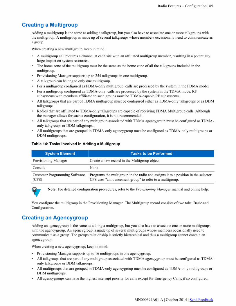
Creating a MultigroupAdding a multigroup is the same as adding a talkgroup, but you also have to associate one or more talkgroups withthe multigroup. A multigroup is made up of several talkgroups whose members occasionally need to communicate asa group.
When creating a new multigroup, keep in mind:
• A multigroup call requires a channel at each site with an affiliated multigroup member, resulting in a potentiallylarge impact on system resources.
• The home zone of the multigroup must be the same as the home zone of all the talkgroups included in themultigroup.
• Provisioning Manager supports up to 254 talkgroups in one multigroup.• A talkgroup can belong to only one multigroup.• For a multigroup configured as FDMA-only multigroup, calls are processed by the system in the FDMA mode.• For a multigroup configured as TDMA-only, calls are processed by the system in the TDMA mode. RF
subsystems with members affiliated to such groups must be TDMA-capable RF subsystems.• All talkgroups that are part of TDMA multigroup must be configured either as TDMA-only talkgroups or as DDM
talkgroups.• Radios that are affiliated to TDMA-only talkgroups are capable of receiving FDMA Multigroup calls. Although
the manager allows for such a configuration, it is not recommended.• All talkgroups that are part of any multigroup associated with TDMA agencygroup must be configured as TDMA-
only talkgroups or DDM talkgroups.• All multigroups that are grouped in TDMA-only agencygroup must be configured as TDMA-only multigroups or
DDM multigroups.
Table 14: Tasks Involved in Adding a Multigroup
System Element Tasks to be Performed
Provisioning Manager Create a new record in the Multigroup object.
Console None
Customer Programming Software(CPS)
Programs the multigroup in the radio and assigns it to a position in the selector.CPS uses "announcement group" to refer to a multigroup.
Note: For detailed configuration procedures, refer to the Provisioning Manager manual and online help.
You configure the multigroup in the Provisioning Manager. The Multigroup record consists of two tabs: Basic andConfiguration.
Creating an AgencygroupAdding an agencygroup is the same as adding a multigroup, but you also have to associate one or more multigroupswith the agencygroup. An agencygroup is made up of several multigroups whose members occasionally need tocommunicate as a group. The groups relationship is strictly hierarchical and thus a multigroup cannot contain anagencygroup.
When creating a new agencygroup, keep in mind:
• Provisioning Manager supports up to 16 multigroups in one agencygroup.• All talkgroups that are part of any multigroup associated with TDMA agencygroup must be configured as TDMA-
only talkgroups or DDM talkgroups.• All multigroups that are grouped in TDMA-only agencygroup must be configured as TDMA-only multigroups or
DDM multigroups.• All agencygroups can have the highest interrupt priority for calls except for Emergency Calls, if so configured.
Radio Features – Configuration | 65
MN000694A01-A | October 2014 | Send Feedback
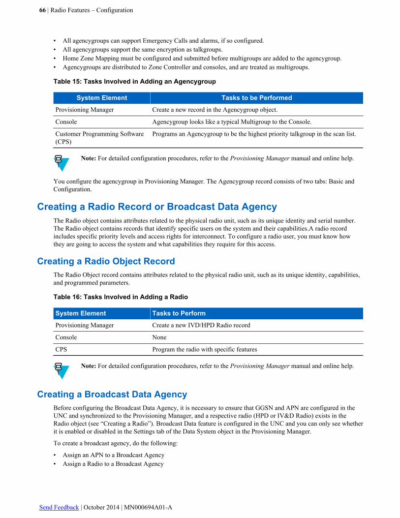
• All agencygroups can support Emergency Calls and alarms, if so configured.• All agencygroups support the same encryption as talkgroups.• Home Zone Mapping must be configured and submitted before multigroups are added to the agencygroup.• Agencygroups are distributed to Zone Controller and consoles, and are treated as multigroups.
Table 15: Tasks Involved in Adding an Agencygroup
System Element Tasks to be Performed
Provisioning Manager Create a new record in the Agencygroup object.
Console Agencygroup looks like a typical Multigroup to the Console.
Customer Programming Software(CPS)
Programs an Agencygroup to be the highest priority talkgroup in the scan list.
Note: For detailed configuration procedures, refer to the Provisioning Manager manual and online help.
You configure the agencygroup in Provisioning Manager. The Agencygroup record consists of two tabs: Basic andConfiguration.
Creating a Radio Record or Broadcast Data AgencyThe Radio object contains attributes related to the physical radio unit, such as its unique identity and serial number.The Radio object contains records that identify specific users on the system and their capabilities.A radio recordincludes specific priority levels and access rights for interconnect. To configure a radio user, you must know howthey are going to access the system and what capabilities they require for this access.
Creating a Radio Object RecordThe Radio Object record contains attributes related to the physical radio unit, such as its unique identity, capabilities,and programmed parameters.
Table 16: Tasks Involved in Adding a Radio
System Element Tasks to Perform
Provisioning Manager Create a new IVD/HPD Radio record
Console None
CPS Program the radio with specific features
Note: For detailed configuration procedures, refer to the Provisioning Manager manual and online help.
Creating a Broadcast Data AgencyBefore configuring the Broadcast Data Agency, it is necessary to ensure that GGSN and APN are configured in theUNC and synchronized to the Provisioning Manager, and a respective radio (HPD or IV&D Radio) exists in theRadio object (see “Creating a Radio”). Broadcast Data feature is configured in the UNC and you can only see whetherit is enabled or disabled in the Settings tab of the Data System object in the Provisioning Manager.
To create a broadcast agency, do the following:
• Assign an APN to a Broadcast Agency• Assign a Radio to a Broadcast Agency
66 | Radio Features – Configuration
Send Feedback | October 2014 | MN000694A01-A

• Assign the appropriate broadcast IP address for each zone that is to have broadcast data enabled. The broadcast IPaddress must be unique for each APN
Broadcast Agency radio assignments can be reassigned as needed.
A radio record that is assigned to a broadcast agency cannot be deleted. Remove the radio's assignment to thatbroadcast agency, or if it is the only radio record assigned to the agency, first delete the Broadcast Agency record andthen the radio record.
Important: For data messaging services, it is critical that IP addresses specified in IVD/HPD Radio objectsand Broadcast Data Agencies do not conflict within a CEN (Customer Enterprise Network). IP addressconflicts may result in loss of data messaging service for the conflicting subscribers.
Once the broadcast agency is created, enter the serial number of the radio to assign the radio to that agency and savethe record. You can assign other radios to the agency after this step is complete.
Note: For detailed configuration procedures, refer to the Provisioning Manager manual and online help.
Creating a Conventional Broadcast Data AgencyNote: Depending on the system version, for detailed configuration procedures, refer to:
• For M core and L core systems, see the Provisioning Manager manual and online help.• For K core systems, see the Configuration Manager – Conventional manual and online help.
Creating a Conventional UnitConventional Voice Unit and Conventional Voice and Data Unit contain information about the conventional unitswithin the system.
A conventional unit ID can be assigned to a conventional subscriber or a dispatch console.
Note: For detailed configuration procedures, refer to the Provisioning Manager manual and online help.
Creating an Application to Conventional Unit MappingThe Application to Conventional Unit Mapping object associates a console application to a conventional unit. Eachconsole application is assigned a conventional unit ID to use when communicating in the system. This ID is used bythe conventional system to uniquely identify the physical console within a Conventional Channel Group.
Note: Only units that are not data capable can be associated.
Note: For detailed configuration procedures, refer to the Provisioning Manager manual and online help.
Creating a Radio UserTable 17: Tasks Involved in Adding a Radio User
System Element Task to be Performed
Provisioning Manager Add the radio user.
The IVD/HPD Radio records contain the information that identifies systemusers and their capabilities.
Table continued…
Radio Features – Configuration | 67
MN000694A01-A | October 2014 | Send Feedback
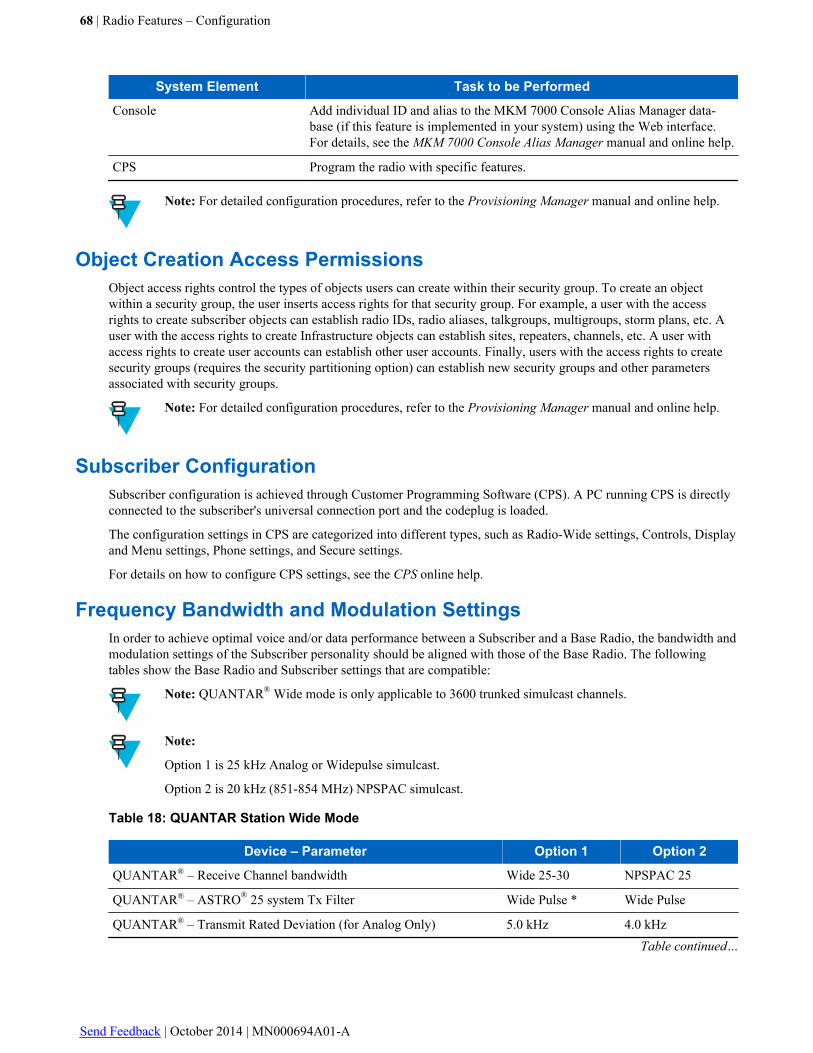
System Element Task to be Performed
Console Add individual ID and alias to the MKM 7000 Console Alias Manager data-base (if this feature is implemented in your system) using the Web interface.For details, see the MKM 7000 Console Alias Manager manual and online help.
CPS Program the radio with specific features.
Note: For detailed configuration procedures, refer to the Provisioning Manager manual and online help.
Object Creation Access PermissionsObject access rights control the types of objects users can create within their security group. To create an objectwithin a security group, the user inserts access rights for that security group. For example, a user with the accessrights to create subscriber objects can establish radio IDs, radio aliases, talkgroups, multigroups, storm plans, etc. Auser with the access rights to create Infrastructure objects can establish sites, repeaters, channels, etc. A user withaccess rights to create user accounts can establish other user accounts. Finally, users with the access rights to createsecurity groups (requires the security partitioning option) can establish new security groups and other parametersassociated with security groups.
Note: For detailed configuration procedures, refer to the Provisioning Manager manual and online help.
Subscriber ConfigurationSubscriber configuration is achieved through Customer Programming Software (CPS). A PC running CPS is directlyconnected to the subscriber's universal connection port and the codeplug is loaded.
The configuration settings in CPS are categorized into different types, such as Radio-Wide settings, Controls, Displayand Menu settings, Phone settings, and Secure settings.
For details on how to configure CPS settings, see the CPS online help.
Frequency Bandwidth and Modulation SettingsIn order to achieve optimal voice and/or data performance between a Subscriber and a Base Radio, the bandwidth andmodulation settings of the Subscriber personality should be aligned with those of the Base Radio. The followingtables show the Base Radio and Subscriber settings that are compatible:
Note: QUANTAR® Wide mode is only applicable to 3600 trunked simulcast channels.
Note:
Option 1 is 25 kHz Analog or Widepulse simulcast.
Option 2 is 20 kHz (851-854 MHz) NPSPAC simulcast.
Table 18: QUANTAR Station Wide Mode
Device – Parameter Option 1 Option 2
QUANTAR® – Receive Channel bandwidth Wide 25-30 NPSPAC 25
QUANTAR® – ASTRO® 25 system Tx Filter Wide Pulse * Wide Pulse
QUANTAR® – Transmit Rated Deviation (for Analog Only) 5.0 kHz 4.0 kHzTable continued…
68 | Radio Features – Configuration
Send Feedback | October 2014 | MN000694A01-A

Device – Parameter Option 1 Option 2
SU (Receive) – Digital Modulator Type Wide Wide
SU – Transmit Deviation (for Analog Only) 5 kHz 4 kHz
SU – Channel Bandwidth 25 kHz 20 kHz
* When RSS configures the QUANTAR® for simulcast operation (Simulcast ENABLED), the ASTRO® 25 systemTx filter is set to WIDE PULSE. However, the ASTRO® 25 system Tx filter can be changed to NARROW PULSEto operate in a 12.5 kHz channel or it can be changed (if necessary) to match the subscriber Rx filter. In either case,the QUANTAR® Tx and Subscriber Rx filters must match. Once the QUANTAR® station is configured for Simul-cast (Simulcast ENABLED) with the ASTRO® 25 system Tx Filter set to WIDE PULSE, if the simulcast setting forthe QUANTAR® station is changed to DISABLED, the ASTRO® 25 system Tx Filter setting will change to NAR-ROW PULSE. However, the ASTRO® 25 system Tx Filter setting can be reconfigured to match the user's channelbandwidth and subscriber Rx filter setting.
Note:
Option 1 is 25 kHz Analog with narrow pulse simulcast.
Option 2 is 20 kHz (851-854 MHz) NPSPAC narrow pulse simulcast.
Option 3 is 12.5 kHz Analog with P25 and 7.7 kHz receive IF bandwidth.
Option 4 is 12.5 kHz Analog with P25 and 6.2 kHz receive IF bandwidth.
Table 19: QUANTAR Station Narrow Mode
Device – Parameter Option 1 Option 2 Option 3 Option 4
QUANTAR® – Receive Channel bandwidth Wide 25-30 NPSPAC 25 Narrow12.5-15
Narrow 12.5
QUANTAR® – ASTRO® 25 system Tx Filter Narrow Pulse Narrow Pulse Narrow Pulse Narrow Pulse
QUANTAR® – Transmit Rated Deviation (for Ana-log Only)
5.0 kHz 4.0 kHz 2.5 kHz 2.5 kHz
SU (Receive) – Digital Modulator Type C4FM C4FM C4FM C4FM
SU – Transmit Deviation
(for Analog Only)
5 kHz 4 kHz 2.5 kHz 2.5 kHz
SU – Channel Bandwidth 25 kHz 20 kHz 12.5 kHz 12.5 kHz
Note: When it is required to receive both C4FM and CQPSK on the same frequency (for example in twodifferent locations), select CQPSK. Some degradation will take place when receiving C4FM.
Note:
Option 1 is 12.5 kHz P25 constant envelope modulation.
Option 2 is 12.5 kHz P25 linear modulation (used for simulcast).
Table 20: GTR 8000 Base Radio Narrow Mode
Device – Parameter Option 1 Option 2
GTR 8000 Base Radio– Receive Channel bandwidth Narrow 12.5 Narrow 12.5Table continued…
Radio Features – Configuration | 69
MN000694A01-A | October 2014 | Send Feedback

Device – Parameter Option 1 Option 2
GTR 8000 Base Radio – Tx Modulation Type C4FM LSM *
SU (Receive) – Digital Modulator Type C4FM CQPSK *
SU – Transmit Deviation (for Analog Only) 2.5 kHz 2.5 kHz
SU – Channel Bandwidth 12.5 kHz 12.5 kHz
* In case of Phase2-TDMA trunking (H-DQPSK modulation), this CSS field is ignored
Programming the MCC 7500 Console
The radio capabilities of a console position are set with the Console User, Console TG/MG Capabilities Profile, andConsole User Capabilities Profile objects.
Note: Configuring the the MCC 7500 console to use conventional channels at an ASTRO® 25 system,release 3.1 site is no different than configuring conventional channels at any other type of site employingconventional channels. For more details on conventional operations, see the Conventional Operationsmanual.
Creating a Console UserA Console User is a user that is able to log on to and use applications in the console subsystem. A Console User hasassociated capabilities that allow or limit the console features to which they have access.
Note: Depending on the system version, for detailed configuration procedures, refer to:
• For M core and L core systems, see the Provisioning Manager manual and online help.• For K core systems, see the Configuration Manager – Conventional manual and online help.
Creating a Console User Capabilities ProfileA Console User Capabilities Profile allows or limits the console features accessible by a console user.
Note: Depending on the system version, for detailed configuration procedures, refer to:
• For M core and L core systems, see the Provisioning Manager manual and online help.• For K core systems, see the Configuration Manager – Conventional manual and online help.
Creating a Console Private Call Resource in the ProvisioningManager
The Console Private Call Resource is a resource that a Console Dispatcher uses to send and receive Private Calls.This record consists of two tabs, Basic and Configuration.
Table 21: Tasks Involved in Adding a Console Private Call Resource
System Element Tasks to Perform
Provisioning Manager Create a new record in the Console Private Call Resource object inProvisioning Manager.
Note: For detailed configuration procedures, refer to the Provisioning Manager manual and online help.
70 | Radio Features – Configuration
Send Feedback | October 2014 | MN000694A01-A

Configuring Call Alert – MCC 7500Note: For detailed configuration procedures, refer to the Provisioning Manager manual and online help.
Radio Features – Configuration | 71
MN000694A01-A | October 2014 | Send Feedback

Chapter
4Radio Features – Operation
This chapter details the tasks that you perform once the radio features are installed and operational on your system.
Record-Related Operations
This section provides information about operations performed on records.
Modifying an Existing RecordThere are no specific procedures for record modification. In order to make the required updates, open a record, makethe changes, and them save them.
Note: For detailed procedures, refer to the Provisioning Manager manual and online help.
Using an Existing Record to Create a New RecordUse the Save As command to create a new record from an existing record. This method of creating records is apreferred shortcut to quickly create many records. This saves time when creating similar groups.
Note: Use “Creating a Talkgroup, Multigroup, or Agencygroup” as a guideline for making the changes.
Note: For detailed procedures, refer to the Provisioning Manager manual and online help.
Multi-creating RecordsThe Provisioning Manager enables you to create many records at once.
For details see “Creating Multiple Records at Once“ in the Provisioning Manager manual.
Multi-editing RecordsThe Provisioning Manager enables you to edit many records at once.
For details see “Editing Multiple Records at Once“ in the Provisioning Manager manual.
Deleting RecordsThe “Deleting a Record in Provisioning Manager” procedure in the Provisioning Manager manual provides anoverview on how to delete a record in Provisioning Manager. See the following sections for specific radio-relatedinformation:
73 | Radio Features – Operation
MN000694A01-A | October 2014 | Send Feedback
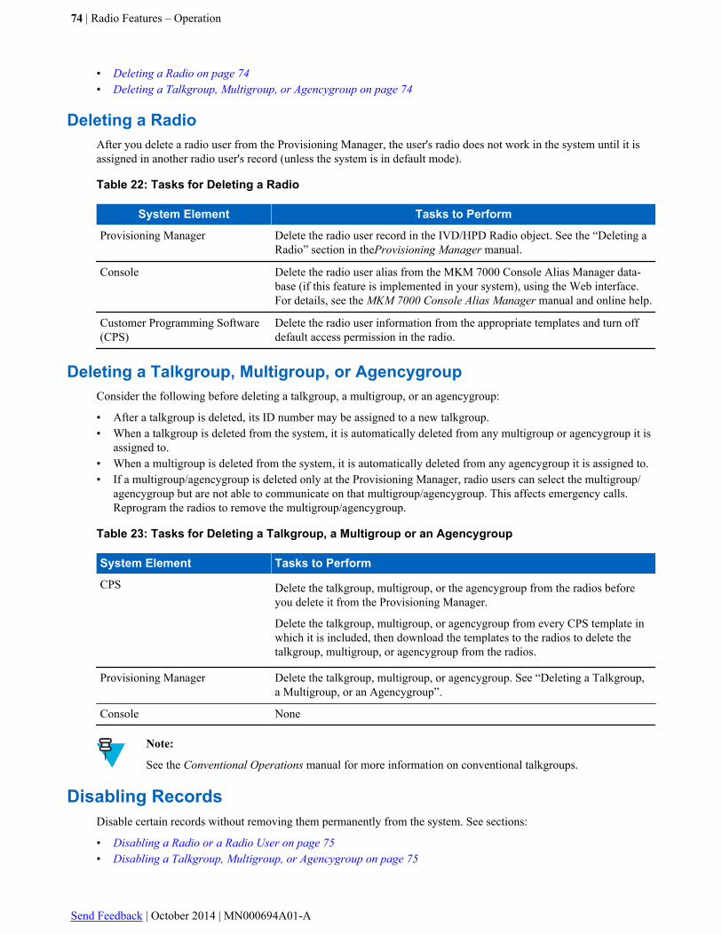
• Deleting a Radio on page 74• Deleting a Talkgroup, Multigroup, or Agencygroup on page 74
Deleting a RadioAfter you delete a radio user from the Provisioning Manager, the user's radio does not work in the system until it isassigned in another radio user's record (unless the system is in default mode).
Table 22: Tasks for Deleting a Radio
System Element Tasks to Perform
Provisioning Manager Delete the radio user record in the IVD/HPD Radio object. See the “Deleting aRadio” section in theProvisioning Manager manual.
Console Delete the radio user alias from the MKM 7000 Console Alias Manager data-base (if this feature is implemented in your system), using the Web interface.For details, see the MKM 7000 Console Alias Manager manual and online help.
Customer Programming Software(CPS)
Delete the radio user information from the appropriate templates and turn offdefault access permission in the radio.
Deleting a Talkgroup, Multigroup, or AgencygroupConsider the following before deleting a talkgroup, a multigroup, or an agencygroup:
• After a talkgroup is deleted, its ID number may be assigned to a new talkgroup.• When a talkgroup is deleted from the system, it is automatically deleted from any multigroup or agencygroup it is
assigned to.• When a multigroup is deleted from the system, it is automatically deleted from any agencygroup it is assigned to.• If a multigroup/agencygroup is deleted only at the Provisioning Manager, radio users can select the multigroup/
agencygroup but are not able to communicate on that multigroup/agencygroup. This affects emergency calls.Reprogram the radios to remove the multigroup/agencygroup.
Table 23: Tasks for Deleting a Talkgroup, a Multigroup or an Agencygroup
System Element Tasks to Perform
CPS Delete the talkgroup, multigroup, or the agencygroup from the radios beforeyou delete it from the Provisioning Manager.
Delete the talkgroup, multigroup, or agencygroup from every CPS template inwhich it is included, then download the templates to the radios to delete thetalkgroup, multigroup, or agencygroup from the radios.
Provisioning Manager Delete the talkgroup, multigroup, or agencygroup. See “Deleting a Talkgroup,a Multigroup, or an Agencygroup”.
Console None
Note:
See the Conventional Operations manual for more information on conventional talkgroups.
Disabling RecordsDisable certain records without removing them permanently from the system. See sections:
• Disabling a Radio or a Radio User on page 75• Disabling a Talkgroup, Multigroup, or Agencygroup on page 75
74 | Radio Features – Operation
Send Feedback | October 2014 | MN000694A01-A
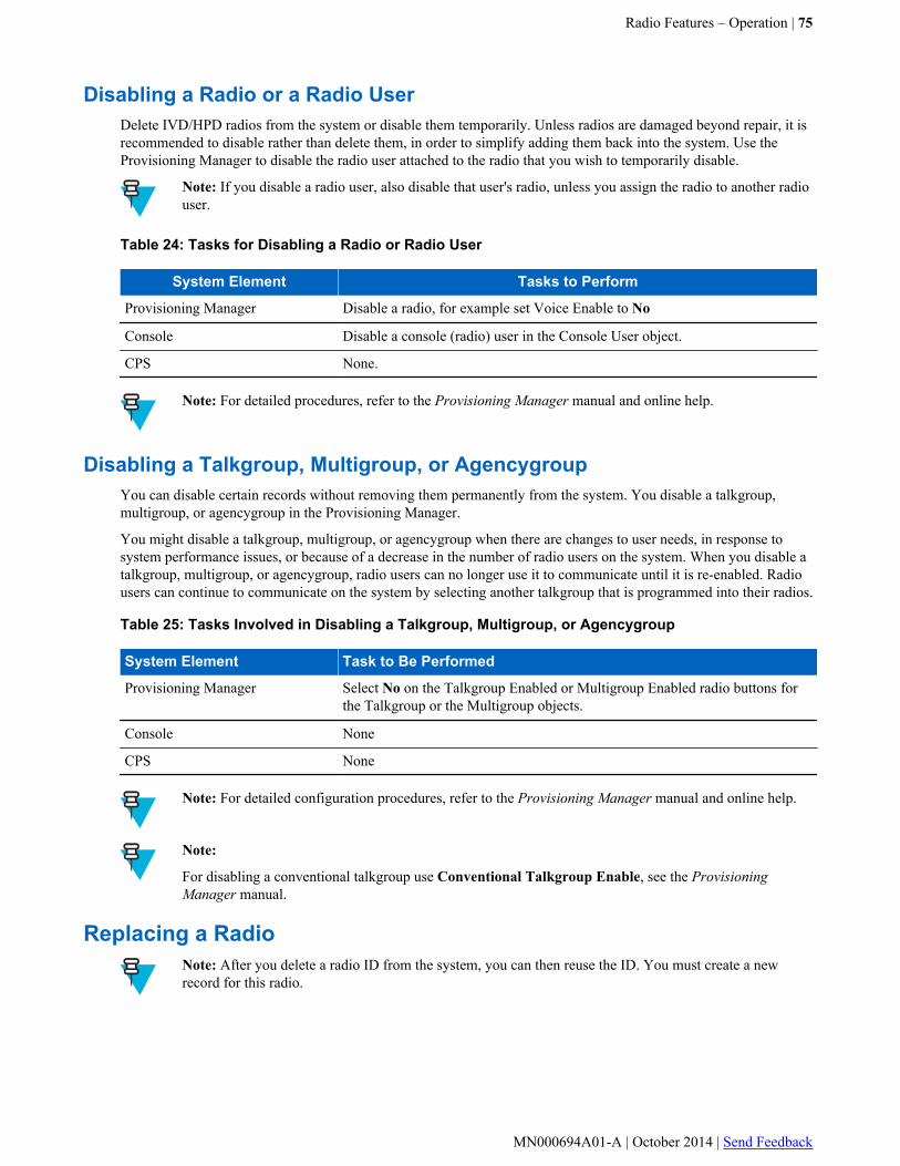
Disabling a Radio or a Radio UserDelete IVD/HPD radios from the system or disable them temporarily. Unless radios are damaged beyond repair, it isrecommended to disable rather than delete them, in order to simplify adding them back into the system. Use theProvisioning Manager to disable the radio user attached to the radio that you wish to temporarily disable.
Note: If you disable a radio user, also disable that user's radio, unless you assign the radio to another radiouser.
Table 24: Tasks for Disabling a Radio or Radio User
System Element Tasks to Perform
Provisioning Manager Disable a radio, for example set Voice Enable to No
Console Disable a console (radio) user in the Console User object.
CPS None.
Note: For detailed procedures, refer to the Provisioning Manager manual and online help.
Disabling a Talkgroup, Multigroup, or AgencygroupYou can disable certain records without removing them permanently from the system. You disable a talkgroup,multigroup, or agencygroup in the Provisioning Manager.
You might disable a talkgroup, multigroup, or agencygroup when there are changes to user needs, in response tosystem performance issues, or because of a decrease in the number of radio users on the system. When you disable atalkgroup, multigroup, or agencygroup, radio users can no longer use it to communicate until it is re-enabled. Radiousers can continue to communicate on the system by selecting another talkgroup that is programmed into their radios.
Table 25: Tasks Involved in Disabling a Talkgroup, Multigroup, or Agencygroup
System Element Task to Be Performed
Provisioning Manager Select No on the Talkgroup Enabled or Multigroup Enabled radio buttons forthe Talkgroup or the Multigroup objects.
Console None
CPS None
Note: For detailed configuration procedures, refer to the Provisioning Manager manual and online help.
Note:
For disabling a conventional talkgroup use Conventional Talkgroup Enable, see the ProvisioningManager manual.
Replacing a RadioNote: After you delete a radio ID from the system, you can then reuse the ID. You must create a newrecord for this radio.
Radio Features – Operation | 75
MN000694A01-A | October 2014 | Send Feedback
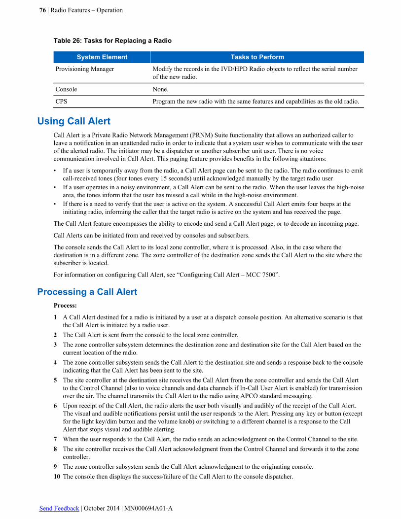
Table 26: Tasks for Replacing a Radio
System Element Tasks to Perform
Provisioning Manager Modify the records in the IVD/HPD Radio objects to reflect the serial numberof the new radio.
Console None.
CPS Program the new radio with the same features and capabilities as the old radio.
Using Call AlertCall Alert is a Private Radio Network Management (PRNM) Suite functionality that allows an authorized caller toleave a notification in an unattended radio in order to indicate that a system user wishes to communicate with the userof the alerted radio. The initiator may be a dispatcher or another subscriber unit user. There is no voicecommunication involved in Call Alert. This paging feature provides benefits in the following situations:
• If a user is temporarily away from the radio, a Call Alert page can be sent to the radio. The radio continues to emitcall-received tones (four tones every 15 seconds) until acknowledged manually by the target radio user
• If a user operates in a noisy environment, a Call Alert can be sent to the radio. When the user leaves the high-noisearea, the tones inform that the user has missed a call while in the high-noise environment.
• If there is a need to verify that the user is active on the system. A successful Call Alert emits four beeps at theinitiating radio, informing the caller that the target radio is active on the system and has received the page.
The Call Alert feature encompasses the ability to encode and send a Call Alert page, or to decode an incoming page.
Call Alerts can be initiated from and received by consoles and subscribers.
The console sends the Call Alert to its local zone controller, where it is processed. Also, in the case where thedestination is in a different zone. The zone controller of the destination zone sends the Call Alert to the site where thesubscriber is located.
For information on configuring Call Alert, see “Configuring Call Alert – MCC 7500”.
Processing a Call AlertProcess:
1 A Call Alert destined for a radio is initiated by a user at a dispatch console position. An alternative scenario is thatthe Call Alert is initiated by a radio user.
2 The Call Alert is sent from the console to the local zone controller.3 The zone controller subsystem determines the destination zone and destination site for the Call Alert based on the
current location of the radio.4 The zone controller subsystem sends the Call Alert to the destination site and sends a response back to the console
indicating that the Call Alert has been sent to the site.5 The site controller at the destination site receives the Call Alert from the zone controller and sends the Call Alert
to the Control Channel (also to voice channels and data channels if In-Call User Alert is enabled) for transmissionover the air. The channel transmits the Call Alert to the radio using APCO standard messaging.
6 Upon receipt of the Call Alert, the radio alerts the user both visually and audibly of the receipt of the Call Alert.The visual and audible notifications persist until the user responds to the Alert. Pressing any key or button (exceptfor the light key/dim button and the volume knob) or switching to a different channel is a response to the CallAlert that stops visual and audible alerting.
7 When the user responds to the Call Alert, the radio sends an acknowledgment on the Control Channel to the site.8 The site controller receives the Call Alert acknowledgment from the Control Channel and forwards it to the zone
controller.9 The zone controller subsystem sends the Call Alert acknowledgment to the originating console.10 The console then displays the success/failure of the Call Alert to the console dispatcher.
76 | Radio Features – Operation
Send Feedback | October 2014 | MN000694A01-A
Using Call Alert in Site TrunkingSite Trunking is a mode of operation when the link to the zone controller fails and the site controller operates the siteas if it were an independent single site system. When operating in the Site Trunking mode, the site has the same CallAlert functionality as in the Wide Trunking mode, but call alerts are processed within one site.
Using the Inbound Event Display
Inbound Event Display (IED) is a feature that supports call-based console technology in which operators can managereceived message and status events in a quiet mode. Quiet mode means that all volumes are turned down or set tozero.
IED is an operator organizational tool that functions as a floating window that appears on top of the radio dispatchmain screen. The IED alerts the operator of new events with a single audible tone. The operator selects andacknowledges that the user has received the radio message or status. When multiple statuses arrive in the queue, theIED default is to put those events on hold. The operator handles events based on highest priority, and deletes an eventwhen the call is completed.
Conventional radio message and status events are sent to the Radio Control Manager (RCM) by default, however,using IED to send these events to the console ensures that a live operator has received the status or message.
Radio Status events is the only type of events that can be displayed on the IED. For MCC 7500 consoles, IED isenabled on a per console basis, using the Provisioning Manager (through the Console Application Platform object).
Note: Route Trunked Status Events to Console field also has to be configured. This can be done in theUnified Network Configurator, the Provisioning Manager provides only read-only information on the valueof this parameter.
The MCC 7500 consoles can display trunked and conventional Radio Status events, conventional Radio Messageevents, and trunked and conventional Emergency Alarm events on their IED.
For details on configuring the Inbound Event Display on an MCC 7500 console, see the MCC 7500/7100 Elite AdminUser’s Guide and the Provisioning Manager manuals.
Using Default Radio User and Talkgroup Records
See Default Radio Access Permissions and Default TG Access Permissions on page 42 for configuration of DefaultRadio and Group Access Permissions
Radio User and Talkgroup Record Download from the ProvisioningManager
After the User Configuration Server (UCS) application database is downloaded and the channel capabilities areverified, the Unified Network Configurator (UNC) begins sending subscriber and talkgroup records to the zonecontroller. The time required for this download varies, depending on the number of subscribers and talkgroups in thesystem.
Note: Any radio, radio user, and talkgroup records added to the UCS server application database during theinitialization period remain in the database until the initialization is complete. Once the initialization iscomplete, the controller replaces the default records with the permanent records as it receives them fromthe Provisioning Manager through the UNC.
Radio Features – Operation | 77
MN000694A01-A | October 2014 | Send Feedback

Data Operation
For information on the use of subscriber radios for data communication, refer to the Trunked Data Services manual,which covers both Enhanced Data Services and IV&D data features.
Using the Remote Monitor
Remote Monitor is a console feature that allows a console position to activate the transmit audio circuitry of thedesired radio and key its transmitter. This allows a console operator to hear what is going on at the subscriber end todetermine the safety and welfare of a radio user.
Some radios can be programmed so that when a Remote Monitor message is received, the radio’s microphone is notturned on, but the radio is keyed. This is called Radio Trace. Radio Trace can be used to help determine the locationof a lost or stolen radio by providing an RF signal from the radio that can be used to track its location.
The Remote Monitor feature can operate in two modes: silent or non-silent. In the silent mode, there is no indicationto the radio user that the Remote Monitor mode is in operation (that is, LEDs do not light, the display does notchange, and the speaker does not unmute for the duration of the Remote Monitor transmission). When the radio isbeing monitored in the non-silent mode, the radio has visual and audio indicators functioning as in normal operation.
Another important option of this feature is the determination of the duration of the Remote Monitor transmission.When a Remote Monitor is initiated, an acknowledgment is always expected from the receiving unit. If, after aspecified period of time, an acknowledgment is not received, the console position attempts to re-send the RemoteMonitor request. Retries are initiated until a total of five attempts have been made to reach the target unit. Theacknowledgment wait period is configurable per conventional channel. During an attempt to accomplish a RemoteMonitor, an "attempting" status message is returned. Upon the reception of an acknowledgment from a receiving unit,the status message indicating that the radio is now being monitored is returned. If an acknowledgment is not received,the error message is returned.
A console position can initiate only one signaling function (for example, Call Alert, Radio Check, or RemoteMonitor) on a resource at a time. If a second signaling function is attempted while the first one is in progress (eithersending another signaling function or waiting for the acknowledgment for a signaling function just sent), then an errormessage is returned. If a resource is in use when the Remote Monitor feature is initiated, then the function waits up to60 seconds to contact that resource. If the resource is still in use after this time, the function is ended and an errormessage is returned.
The retries of the Remote Monitor request in progress can be aborted. When Remote Monitor processing is ended dueto a console operator request, a status message is provided. When a console operator attempts to abort a RemoteMonitor request that is not in progress, the error message is returned, indicating that the Remote Monitor requestcannot be aborted.
Once the radio has acknowledged the Remote Monitor request, the console operator cannot stop the Remote Monitorfunction. If a console position becomes disabled while sending a Remote Monitor request or waiting for theacknowledgment for a Remote Monitor request just sent, then Remote Monitor processing is ended. If a consoleoperator attempts to send or abort a Remote Monitor request on a disabled console position, then an error message isreturned.
Refer to the “Creating a Console TG/MG Capabilities Profile” section for information on how to configure theRemote Monitor feature.
78 | Radio Features – Operation
Send Feedback | October 2014 | MN000694A01-A

Chapter
5Radio Features – Troubleshooting
This chapter describes troubleshooting of subscribers within the system, including voice quality, unit failure, voiceconnectivity, and data connectivity issues. For more detailed information, refer to the Call Processing and MobilityManagement or the Fault Management manuals.
Considerations for Radio Use
When operating a radio, consider the following:
• Hold the radio in a vertical position in front of your face with the microphone (and other parts of the radioincluding the antenna) at least 1 to 2 inches (2.5 cm to 5 cm) away from the lips. Keeping the radio at a properdistance is important since RF exposures decrease with (increasing) distance from the antenna.
• For body-worn operation, always place the radio in a Motorola-approved clip, holder, holster, case, or bodyharness, if available for the product. (All Motorola-approved accessory, antenna, and device combinations complywith Federal Communications Commission (FCC) occupational/controlled environment RF exposure limits.Exposure information on various accessory, antenna, and device combinations are found under the DisplayExhibit section of http://www.fcc.gov/oet/fccid. Search for the FCC ID number, which is obtained from the labelof your radio). Use of non-Motorola-approved accessories may result in exposure levels which exceed the FCC'soccupational/controlled environment RF exposure limits.
• If you are not using a body-worn accessory and are not using the radio in the intended use position in front of theface, then ensure that the antenna and the radio are kept 2.5 cm (1 inch) from the body when transmitting. Keepingthe radio at a proper distance is important since RF exposures decrease with (increasing) distance from theantenna.
• The feature to expand the number of adjacent sites for a subscriber radio is only available to Expanded AdjacentSite Broadcast-capable subscriber radios. It is not applicable to radios operating on the 3600 sites attached toSmartX Site Converters.
Subscriber Radio Voice Connectivity
Voice connectivity for a subscriber radio user communicating with other subscriber radio users may be impacted for anumber of different reasons, including the following:
• Improper programming at the radio or the Provisioning Manager database• Failed subscriber unit• Failed RF infrastructure component, such as a base station• Incorrect key usage• Lack of keys in subscriber radios• Improper user manipulation of key sets
79 | Radio Features – Troubleshooting
MN000694A01-A | October 2014 | Send Feedback
Note: If an Sub-Band Restricted (SBR) radio is currently active in a talkgroup call and roams into an RFsite that has a non-SBR channel assigned to that talkgroup call, then the SBR radio does not receive theaudio since it cannot operate on a non-SBR channel. Following the end of the current transmission, thesystem transmission trunks the call to enable the call to be set up on an SBR channel upon the nexttransmission request. For the multigroup scan scenario, any radio that is currently in the multigroup scanmode is excluded from a talkgroup call if the talkgroup is associated with the multigroup and there areother talkgroup-affiliated radios registered at the same RF site. In this case, the radio that is in multigroupscan mode does not receive audio for this call.
Digital Audio Quality
Poor audio quality can be caused by a number of factors in an ASTRO® 25 system. Some factors are the same asthose found in an analog system. Others are related with the technology used to handle digital signals and convertthem to and from analog signals.
Among the causes of poor digital audio quality are:
• Users speaking too close to the microphone• Users not enunciating clearly• Poor line characterization• Poor optimization• Degradation of an audio circuit, such as excessive thermal noise due to a failing component• Intermittent failure of a device, module, or a link• Total failure of a device, module, or a link
Subscriber Radio Wireless Data Network Connectivity
A user is disconnected from the wireless data network due to the following reasons:
• Improper programming• Failed subscriber unit• Failed RF infrastructure component, such as a base station• Incorrect configuration of the PDG database
Subscriber Unit Failure
The failure of a subscriber unit results in that unit being unable to communicate. The failure does not affect otherradio users in the talkgroup, site, or zone.
SmartZone Radio Call Failure
If you are experiencing problems communicating with a talkgroup, you can check the Provisioning Manager/UNCconfiguration for the radio and the SmartX device/site. Alternatively, you can consult the list of possible problemsprovided below.
SmartZone® (3600) site alarms are sent to the SmartX site converter, which then passes them onto the ProvisioningManager. The ASTRO® 25 system event browser receives the following alarms from the SmartZone® network:
• Site Controller Malfunction
80 | Radio Features – Troubleshooting
Send Feedback | October 2014 | MN000694A01-A

• Channel Malfunction• 3600 Link Down Due to Zone Controller Link Down• Site Equipment Comm Failure Due to Zone Controller Link Down• Malfunction State Due to Loss of T1/E1 Sync• T1/E1 Misconfiguration• Link to SmartX Site Converter Down
Radio Features – Troubleshooting | 81
MN000694A01-A | October 2014 | Send Feedback


