CertPrs8/CWTSTM Certified Wireless Technology Specialist Study Guide/Tom Carpenter/534-2/Chapter 2
Every communication’s technology must have a medium to travel along in order to pass information between two devices. Ethernet networks pass this information along coaxial cable or some other cable such as UTP. Traditional analog telephone networks use wiring.
The playground communication toys that so many children enjoy talking into use tubes running through the ground, and the old cup-and-string technique uses the string as the medium for transfer. Wireless networks, specifically Wi-Fi, RFID, Bluetooth, and WiMAX, use radio frequency (RF) waves as the medium, and IrDA-based communications use another electromagnetic technology known as infrared.
In this chapter, you will learn about RF, including its behavior and functionality. You will learn about the methods used to measure RF waves and the various languages spoken on an RF-based network. When you are finished, you will also understand the environmental impact on RF capabilities and communications.
RF DefinedIt should be immediately clear that there are at least two important words related to RF that need to be defined; however, there is a third word that also needs to be defined to fully understand RF. These three words are
■ Radio
■ Frequency
■ Signal
The radio is the device that generates and receives the signal known as an RF signal, and this signal is transmitted on a specific frequency. The frequency is what distinguishes one RF channel from another. Technically, the number of times per second the signal cycles or repeats a particular waveform is the source of the frequency identification. This definition means that a signal operating at the 2.4 GHz frequency is cycling 2,400,000,000 times per second (1 GHz = 1 billion cycles per second and 1 MHz = 1 million cycles per second).
Electric energy can be made to vary over time. This variance in electrical energy is known as a signal. There are two general categories of signals: digital and analog. The sine wave is an example of an analog signal.
Figure 2-1 illustrates a sine wave. As time passes, the intensity of the sine wave increases to some maximum point (point A) and then returns to the baseline (point 0). The wave’s intensity decreases to some minimum point (point B) and then returns
ch02.indd 50 9/16/09 4:15:10 PM
RF Defi ned 51
CertPrs8/CWTSTM Certified Wireless Technology Specialist Study Guide/Tom Carpenter/534-2/Chapter 2
to the baseline again. This process continues over time. By adjusting the number of cycles (going from point 0 to A to 0 to B to 0) in a given window of time, you adjust the frequency. Figure 2-1 represents two cycles of the wave.
Digital signals differ from analog signals in that the digital signal varies abruptly between two electrical values as depicted in Figure 2-2, and the analog signal varies gradually, as was demonstrated in Figure 2-1. Digital signals are used to communicate and relay information within computer networks, but they are not used as carriers of information in RF networks. Only analog signals are used as carriers of information in RF networks. The information being carried by the RF waves may be digital or analog, but it is encoded (carried) on analog signals in an RF-based network connection.
An analog carrier signal can carry data represented by analog or digital techniques. This carrying of an information signal on a carrier signal is known as modulation. Modulation has been utilized for decades; one well-known example is the modem. The mod in modem stands for modulator, and the dem stands for demodulator. Much as a modem modulates and demodulates information traveling on a telephone wire, an RF radio modulates data onto the RF medium and demodulates data received through the medium. The sending of this signal from the radio out through the antenna is known as radiation.
A A
0 0 0 0 0Time
Intensity of the Signal
B B
FIGURE 2-1
The sine wave
Time
Intensity of the Signal FIGURE 2-2
Digital signal
ch02.indd 51 9/16/09 4:15:11 PM
52 Chapter 2: Radio Frequency Basics
CertPrs8/CWTSTM Certified Wireless Technology Specialist Study Guide/Tom Carpenter/534-2/Chapter 2
While the exact phrase carrier wave may not be referenced on the CWTS exam, it is an important concept in wireless communications. Wireless engineers and technicians must deal with many different wireless technologies. In the 802.11 standard (as amended) alone, you are dealing with four or more different modulation methods, and this does not include the newest 802.11n modulation techniques provided by the High Throughput PHY. Therefore, a brief summary of carrier waves and why they are important is in order.
Tom Standage’s exceptional book The Victorian Internet (Walker & Company, 2007) documents the many signaling techniques we as humans have used throughout the recent centuries. For example, the book documents how Claude Chappe and his brother commu-nicated over great distances with time-bound audio signals. The signal was unary in nature in that there was only one signal: the clanging of a pot. However, the brothers had synchro-nized their clocks so that a clang was linked to a second on the clock and each number was linked to a letter; thus a message could be sent. If the transmitting brother clanged the pot when the second hand was pointing to 12, the listening (receiving) brother knew to translate the number 12 into the appropriate message.
As you can imagine, this system would not allow for rapid communications, but it did allow for communications over a short distance. Eventually, the brothers realized that sound waves were not good carriers of signals (since
they attenuate so quickly and they take so long to arrive at the destination), so they developed a new system based on visual cues. Using a simple black-and-white two-sided panel (black on one side and white on the other) and a telescope, the brothers successfully communicated over a distance of approximately ten miles.
What did both of these communications devices have in common? They both used waves to carry a signal. The first used sound waves, and the second used light waves. Since light waves travel much faster than sound waves, the latter device worked much better and over greater distances.
However, a dilemma remained. Both of these early devices required a human interpreter on the other end at all times. The instrument of the human ear and the instrument of the human eye were used to interpret the data that was carried on the sound and light waves, respectively. In order to send information without a human interpreter, scientists and engineers had to develop concepts and tools related to electricity.
Today’s carrier waves are almost always electromagnetic waves. Mechanical devices can be formed that transmit the waves and also receive the waves. This means that data can be sent and received by modulating the data onto the waves. For example, the fre-quency can be modified to represent a binary 1 or a binary 0. The wave is generated, but it is manipulated in such a way that it carries binary data, and this makes it a carrier wave.
INSIDE THE EXAMINSIDE THE EXAM
Carrier Waves
ch02.indd 52 9/16/09 4:15:11 PM
RF Range and Speed Factors 53
CertPrs8/CWTSTM Certified Wireless Technology Specialist Study Guide/Tom Carpenter/534-2/Chapter 2
As discussed in Chapter 1, all that is needed to represent digital data is some form of variance between two states. The analog or digital signals carried across the RF signals from device to device on a wireless network provide this variance.
CERTIFICATION OBJECTIVE 2.01
RF Range and Speed FactorsTo effectively implement an RF-based network, the factors that impact the distance or range of RF signals must be understood. Of course, the speed of the communications must be considered as well. Stronger signals result in increased data rates, and weaker signals result in decreased data rates. Issues such as line of sight, first Fresnel zone clearance, interference devices, and standard RF behavior become very important when setting up a wireless network.
In addition to the factors covered in this section, the wireless technology specialist must always remember that RF signals weaken as they travel. When a receiver is located farther from the transmitter, the signal will be weakened. At some point, the signal will become so weak that it is unusable. This natural behavior is known as free space path loss. As the signal travels along the free space path, energy is lost due to the broadening of the wave front. The result is a weakened signal at a given detection point.
Line of SightLine of sight (LOS) is the seemingly straight line from the object in view (the transmitter) to the observer’s eye (the receiver). This is also called the visual line of sight. The LOS is a seemingly straight line because, in fact, light waves travel in a similar fashion to RF waves.
Light waves can bounce off objects and be redirected. A mirror demonstrates this well. Stand directly in front of a mirror and note what you can see in the mirror. Now take a step to your right or left and note what you can see. You should see more objects or information in the opposite direction of the move. For example, if you step to your right, you’ll now see more items that are actually located to your left and vice versa.
ch02.indd 53 9/16/09 4:15:11 PM
54 Chapter 2: Radio Frequency Basics
CertPrs8/CWTSTM Certified Wireless Technology Specialist Study Guide/Tom Carpenter/534-2/Chapter 2
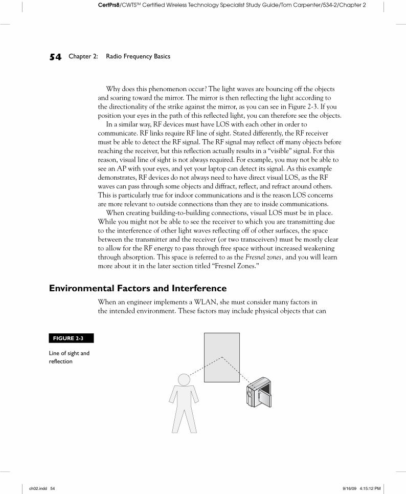
Why does this phenomenon occur? The light waves are bouncing off the objects and soaring toward the mirror. The mirror is then reflecting the light according to the directionality of the strike against the mirror, as you can see in Figure 2-3. If you position your eyes in the path of this reflected light, you can therefore see the objects.
In a similar way, RF devices must have LOS with each other in order to communicate. RF links require RF line of sight. Stated differently, the RF receiver must be able to detect the RF signal. The RF signal may reflect off many objects before reaching the receiver, but this reflection actually results in a “visible” signal. For this reason, visual line of sight is not always required. For example, you may not be able to see an AP with your eyes, and yet your laptop can detect its signal. As this example demonstrates, RF devices do not always need to have direct visual LOS, as the RF waves can pass through some objects and diffract, reflect, and refract around others. This is particularly true for indoor communications and is the reason LOS concerns are more relevant to outside connections than they are to inside communications.
When creating building-to-building connections, visual LOS must be in place. While you might not be able to see the receiver to which you are transmitting due to the interference of other light waves reflecting off of other surfaces, the space between the transmitter and the receiver (or two transceivers) must be mostly clear to allow for the RF energy to pass through free space without increased weakening through absorption. This space is referred to as the Fresnel zones, and you will learn more about it in the later section titled “Fresnel Zones.”
Environmental Factors and InterferenceWhen an engineer implements a WLAN, she must consider many factors in the intended environment. These factors may include physical objects that can
FIGURE 2-3
Line of sight and reflection
ch02.indd 54 9/16/09 4:15:12 PM
RF Range and Speed Factors 55
CertPrs8/CWTSTM Certified Wireless Technology Specialist Study Guide/Tom Carpenter/534-2/Chapter 2
weaken or redirect the RF signals, and they may include other devices that can interfere with intentional radio transmissions. The first environmental factors that will be considered relate to outdoor links and the needed RF line of sight for communications to occur.
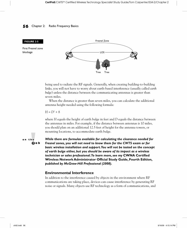
Fresnel ZonesThe first Fresnel (pronounced fra-nel) zones are areas centered on the visible LOS between the transmitting and receiving antennas and were discovered by Augustin-Jean Fresnel of France. They do not form a square area, but rather one that is ellipse shaped. As Figure 2-4 shows, the Fresnel zones are narrower toward the antennas and wider in the middle. These Fresnel zones come about because an antenna does not transmit RF waves in a laser-type beam, but rather the RF waves propagate (or spread) as they travel through the air.
For effective RF communications, 60 percent of the first Fresnel zone should remain unblocked by objects such as trees and buildings. To be safe, you should err on the side of caution and make sure no more than 20 percent of the first Fresnel zone is blocked—or that at least 80 percent is clear. Trees and buildings in the first Fresnel zone will absorb some of the RF energy (see Figure 2-5) or reflect it off the intended path. When this occurs too much, while you might still have visual LOS, RF LOS is unavailable or blocked. You might say that the receiver cannot see enough of the RF signal.
Engineers should review the environment between building-to-building links periodically. It is better to discover that a tree is growing or that a new building is being constructed in the first Fresnel zone before blockage occurs so that you can deal with it effectively.
For very long-distance links, the earth itself may intrude upon the first Fresnel zone. This is because the earth is round and the center LOS within the first Fresnel zone is a straight line. Also, the longer the link, the larger the first Fresnel zone becomes. When and if this blockage occurs depends on the height of the antennas
Fresnel Zone
LOS
FIGURE 2-4
The Fresnel zones
ch02.indd 55 9/16/09 4:15:13 PM
56 Chapter 2: Radio Frequency Basics
CertPrs8/CWTSTM Certified Wireless Technology Specialist Study Guide/Tom Carpenter/534-2/Chapter 2
being used to radiate the RF signals. Generally, when creating building-to-building links, you will not have to worry about earth-based interference (usually called earth bulge) unless the distance between the communicating antennas is greater than seven miles.
When the distance is greater than seven miles, you can calculate the additional antenna height needed using the following formula:
H = D2 ÷ 8
where H equals the height of earth bulge in feet and D equals the distance between the antennas in miles. For example, if the distance between antennas is 10 miles, you should plan on an additional 12.5 feet of height for the antenna towers, or mounting locations, to accommodate earth bulge.
While there are formulas available for calculating the clearance needed for Fresnel zones, you will not need to know them for the CWTS exam or for basic wireless installation and support. You will not be tested on the concept of earth bulge either, but you should be aware of its impact as a wireless technician or sales professional. To learn more, see my CWNA Certified Wireless Network Administrator Official Study Guide, Fourth Edition, published by McGraw-Hill Professional (2008).
Environmental InterferenceIn addition to the interference caused by objects in the environment where RF communications are taking place, devices can cause interference by generating RF noise or signals. Many objects use RF technology as a form of communications, and
Fresnel Zone
Tree Tree
LOS
FIGURE 2-5
First Fresnel zone blockage
ch02.indd 56 9/16/09 4:15:14 PM
RF Range and Speed Factors 57
CertPrs8/CWTSTM Certified Wireless Technology Specialist Study Guide/Tom Carpenter/534-2/Chapter 2
others use RF energy for alternative purposes or generate RF energy as a side effect. The most common of these include the following:
■ Microwave ovens
■ Elevator motors
■ Baby monitors
■ Spread spectrum phones
■ Bright sunlight
Many WLAN administrators refer to the Fresnel zone when it is more proper to refer to the first Fresnel zones according to the science of Physics. While it may be the intention of most WLAN administrators to reference the first Fresnel zone when they speak of only the Fresnel zone, it is important that you under-stand the difference. The first Fresnel zone is the zone with the greatest impact on a WLAN link in most scenarios. The Fresnel zones have been described as an ellipsoid-shaped area, an American football-shaped area, and even a Zeppelin-shaped area.
Why the big deal about zones versus zone? There are actually multiple Fresnel zones in layers surrounding the visual LOS. The first Fresnel zone, what I call 1FZ, is the most important one for wireless engineers creating outdoor links. If we say that the Fresnel zones
must be blocked at a rate no higher than 20 percent, then we have asked for the impos-sible, as Fresnel zones continue out in layers to a theoretical ever-weakening infinity. For this reason, it is best to think of the first Fresnel zone only as you design your links. There are even formulas for calculating the widest point in the Fresnel zone so that you can ensure the blockage is not beyond acceptable levels.
While you will not need to know the formulas for the CWTS exam, you should understand that the first Fresnel zone should not be blocked by more than 40 percent and most use a conservative rule of 20 percent. If you see the term Fresnel zone instead of the explicit declaration of first Fresnel zone, as-sume that the topic in question is indeed the first Fresnel zone.
INSIDE THE EXAMINSIDE THE EXAM
Fresnel Zones
ch02.indd 57 9/16/09 4:15:15 PM
58 Chapter 2: Radio Frequency Basics
CertPrs8/CWTSTM Certified Wireless Technology Specialist Study Guide/Tom Carpenter/534-2/Chapter 2
Microwave ovens and elevators generate what is called RF noise, as they are not designed with the intention of transmitting information. However, this noise can prevent devices from transmitting information intended for delivery as an intelligent message. Think of it like this: If you are in a room talking with a friend and suddenly fifty people come into the room and start yelling at each other, will you still be able to hear your friend? You’ll probably miss all or part of what your friend is saying. This same problem is faced by the RF receiver, for example, a baby monitor in the kitchen, that is trying to “hear” what the RF transmitter (the monitor in the baby’s room) is sending to it while a microwave oven is screaming (transmitting unintentional RF waves) in the background.
If you have ever wondered how a microwave oven heats food, you are about to find out. When RF energy is absorbed into an object, it is converted to heat. Water is a great absorber of RF energy, and this is why liquid objects get hot when placed in the microwave. Try placing a dry piece of paper in the microwave; it won’t heat up. This is because the dry paper is not a good absorber of RF energy like a bowl of soup is. This is the same reason you must use the right cabling and connectors when building a wireless network. Use the wrong devices in the wrong places and you could get a meltdown—seriously.
Baby monitors and spread spectrum phones, such as a 2.4 GHz cordless phone, can also cause interference as they are generating RF signals intentionally in the environment. You can often resolve interference issues by changing channels on your wireless networking devices.
A final source of interference is the weather. Bright sunlight (light is a part of the complete electromagnetic spectrum) can cause reduced bandwidth or communications capabilities, and severe stormy weather can also cause problems.
Just as the RF energy is absorbed into water in a microwave oven, RF energy can be absorbed by raindrops falling through the RF link path. Rain can reduce the signal strength at the receiver and possibly lower it enough to disrupt communications, though this scenario is an extreme one, likely requiring more than five to six inches of rainfall per hour for links of less than two to three miles.
Motors, wireless devices, and weather can all interfere with WLAN communications. These items should be considered during a site survey, and you should remember them for the exam.
ch02.indd 58 9/16/09 4:15:15 PM
RF Signal Characteristics 59
CertPrs8/CWTSTM Certified Wireless Technology Specialist Study Guide/Tom Carpenter/534-2/Chapter 2
Interference types, like those mentioned previously, could be categorized as narrowband interference or all-band interference. Narrowband interference, as the name implies, interferes with a small part of the spectrum, and you can usually solve the problem by changing channels within the wireless devices. All-band interference, on the other hand, requires using more extreme measures such as changing wireless technologies. For example, you might need to switch to an 802.11a device instead of an 802.11b/g device, if the entire 2.4 GHz spectrum is being used by others. This scenario occurs commonly in shared office spaces such as malls and leased office buildings.
CERTIFICATION OBJECTIVE 2.02
RF Signal CharacteristicsRadio frequency communications occur within many different environments, and these various environments introduce problems and advantages for the RF signals. What is generally considered an advantage in RF communications is called gain and that which is usually seen as a problem is called loss. It is important to understand these two concepts if you are to appreciate the full impact of the RF behavior in any given environment.
Understanding Gain and LossAs a wireless technician, it is very important to understand gains and losses in RF-based communications. Without this understanding, you will be unable to effectively plan a WLAN. As an example, I installed a small WLAN in a church recently, and the design of the church was that of a “T” structure. The front of the church includes the entry foyer in the center with hallways leading to Sunday School rooms and administrative offices to the right and the left. These sections form the top of the “T.” The sanctuary and fellowship hall form the leg of the “T.” The result is a nonrectangular coverage area.
In order to make the WLAN work, I had to understand how building materials in walls attenuate (cause loss to) the RF signals. In order to configure the access points correctly, I needed to understand passive and active gain. Passive gain was impacted by the use of appropriate antennas. Active gain was impacted by the adjustment of output power levels in the access points. Drawing on my understanding of RF propagation,
ch02.indd 59 9/16/09 4:15:15 PM
60 Chapter 2: Radio Frequency Basics
CertPrs8/CWTSTM Certified Wireless Technology Specialist Study Guide/Tom Carpenter/534-2/Chapter 2
gains, and losses, I was able to intuit the best locations for the access points in this very small installation without advanced site survey procedures. The next two sections will explain gains and losses so that you can eventually do the same.
GainAmplitude is a measurement of the change in RF energy caused by a passing RF wave. This is much like the voltage level in an electrical signal. A signal that is transmitted at higher amplitude is more likely to provide a strong signal at the receiver. An increase in amplitude of the RF signal is known as gain.
Gain is either active or passive. Active gain is achieved by adding an amplifier (you will learn about these devices in Chapter 4) in-line between the RF signal generator, such as a wireless access point, and the radiating antenna. Adding an amplifier increases the signal strength in a literal way in that the signal is actually strengthened before it reaches the antenna. Passive gain does not actually increase the signal strength but directs it. Passive gain is achieved by using semidirectional or highly directional antennas to focus the energy of the signal in a more specific direction.
To understand passive gain, think of water spraying out of a water hose. Imagine the water volume is equivalent to the RF signal strength. If you let the water flow out of the end of the hose without focusing it, it may spray for a few feet; however, if you focus the volume of water by putting your thumb over a portion of the hose end, the water will spray many times farther. Note that you have not increased the volume (understood as RF energy in this analogy), but you have increased the distance that same volume is traveling. A directional antenna focuses the beamwidth toward a specific location in the same way. The result is that more energy is focused in a particular direction and the signal is stronger in that direction. This behavior results in a stronger signal at receiving points in the intended direction than would be available with a lower-gain antenna.
All devices, including connectors and cabling, in the path of the RF signal leading up to the antenna have the potential to either increase the strength (amplify) or decrease the strength (attenuate) of the signal. Once the signal leaves the antenna and is propagated through the air in the form of RF waves, it will experience only a weakening in strength until it arrives at the receiving antenna because of various environmental behavior factors discussed shortly in “RF Behavior.”
LossWhen signal strength is weakened, we refer to it as loss. Loss is a decrease in the amplitude of the signal. Signal loss can occur within the cabling of the wireless
ch02.indd 60 9/16/09 4:15:16 PM
RF Signal Characteristics 61
CertPrs8/CWTSTM Certified Wireless Technology Specialist Study Guide/Tom Carpenter/534-2/Chapter 2
devices and infrastructure and when the antenna sends the signal through the air as RF waves.
Cables and connectors can cause loss because of the resistance they impose. When this loss occurs in the cabling and connectors, the temperature of the cables will usually increase. The AC electrical signal is absorbed as it travels on the wire (the signal travels the wire as an AC electrical signal and is converted to an RF wave by the antenna) because of resistance.
If the impedance of the cables and connectors does not match, you have an impedance mismatch that causes power to be reflected back toward the source. Less energy can be transmitted forward, as some has been reflected backward, and this
The preceding section mentioned the term beamwidth. The beamwidth of an antenna is defined as a measurement from the center of the RF signal to the points on the vertical and horizontal axes where the signal strength decreases by three decibels, or half power. To help you understand this, consider the analogy of a flashlight beam.
You may have used flashlights with adjust-able beams. These flashlights usually allow you to turn a dial and focus the beam to become broader or narrower. If you shine the light on a wall, you will see a very bright center beam surrounded by ever-dimming rings of light. As you make adjustments to the beam, the circles of light stretch outward and inward. This be-havior is similar to the concept of beamwidths.
Of course, different antennas offer different beamwidths. Omnidirectional antennas
radiate signals out in all directions around the antenna very evenly and they radiate these signals in a fairly high vertical swath as well. In fact an omnidirectional antenna will usually have a beamwidth of somewhere around 50 to 60 degrees. A parabolic dish or grid antenna (both of which look similar to a satellite dish) may have a beamwidth as low as 4 degrees and rarely higher than 20 degrees. Do you see the difference? The antenna that focuses the energy more is used in long-distance links (the parabolic dish) and the antenna that focuses the energy less is used for indoor and area coverage WLANs (omnidirectional). This understanding of beamwidths will help you on the CWTS exam, but it will also help you as you select the appropriate antennas for a given installation scenario.
INSIDE THE EXAMINSIDE THE EXAM
Beamwidth
ch02.indd 61 9/16/09 4:15:16 PM
62 Chapter 2: Radio Frequency Basics
CertPrs8/CWTSTM Certified Wireless Technology Specialist Study Guide/Tom Carpenter/534-2/Chapter 2
creates a loss in signal amplitude. In worst-case scenarios, this reflection can even damage equipment.
As the RF wave travels through the environment, through walls, through humans (yes, they pass right through you) and animals, and even through the air, some of its energy will be lost because of absorption and other RF behaviors. The most damaging environmental objects are generally those with high moisture levels—water is an excellent absorbent of RF energy.
Loss can also occur intentionally. Because the FCC regulates the power output of RF signals from your antenna, you may need to reduce the signal strength intentionally before it leaves the antenna. Signal strength is reduced before radiation using an RF attenuator.
Because receivers have a sensitivity threshold, you must account for gains and losses. A signal leaving an antenna without the needed strength demanded by the receiver, the distance, and the environment will not reach its intended destination with sufficient signal strength.
RF BehaviorAfter RF waves leave the antenna and begin to travel through the environment in which communications must occur, many behavioral factors influence the results achieved. Understanding the behavior of RF waves is essential to configuring a working wireless network in small or large environments.
Most of these behaviors will be easy for you to understand, as they are similar to what you have learned through experience with light. Remembering that light is part of the electromagnetic spectrum and has a similar behavior to RF will help you understand these behaviors.
SCENARIO & SOLUTIONYou are transmitting an RF signal and are concerned about the weakening signal strength. The signal must pass through many feet of cabling and connectors before reaching the radiating antenna. The result is a weakening of the signal strength. What is the phenomenon called?
This is called loss. When the signal strength is weakened, it is called loss. When the signal strength is increased, it is called gain. Loss may be intentional or natural. Intentional losses are created by inserting an attenuator between the RF generation device and the radiating antenna. Natural losses occur due to the normal behaviors of RF signals as they travel over wires and through space.
ch02.indd 62 9/16/09 4:15:16 PM
RF Signal Characteristics 63
CertPrs8/CWTSTM Certified Wireless Technology Specialist Study Guide/Tom Carpenter/534-2/Chapter 2
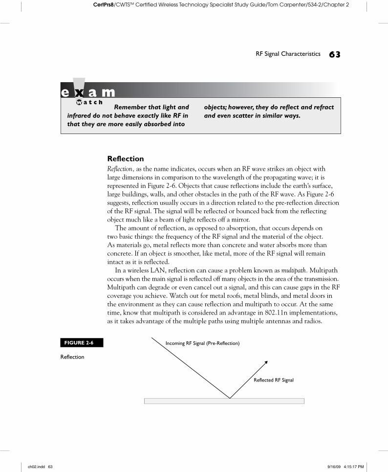
ReflectionReflection, as the name indicates, occurs when an RF wave strikes an object with large dimensions in comparison to the wavelength of the propagating wave; it is represented in Figure 2-6. Objects that cause reflections include the earth’s surface, large buildings, walls, and other obstacles in the path of the RF wave. As Figure 2-6 suggests, reflection usually occurs in a direction related to the pre-reflection direction of the RF signal. The signal will be reflected or bounced back from the reflecting object much like a beam of light reflects off a mirror.
The amount of reflection, as opposed to absorption, that occurs depends on two basic things: the frequency of the RF signal and the material of the object. As materials go, metal reflects more than concrete and water absorbs more than concrete. If an object is smoother, like metal, more of the RF signal will remain intact as it is reflected.
In a wireless LAN, reflection can cause a problem known as multipath. Multipath occurs when the main signal is reflected off many objects in the area of the transmission. Multipath can degrade or even cancel out a signal, and this can cause gaps in the RF coverage you achieve. Watch out for metal roofs, metal blinds, and metal doors in the environment as they can cause reflection and multipath to occur. At the same time, know that multipath is considered an advantage in 802.11n implementations, as it takes advantage of the multiple paths using multiple antennas and radios.
Remember that light and infrared do not behave exactly like RF in that they are more easily absorbed into
objects; however, they do reflect and refract and even scatter in similar ways.
Incoming RF Signal (Pre-Reflection)
Reflected RF Signal
FIGURE 2-6
Reflection
ch02.indd 63 9/16/09 4:15:17 PM
64 Chapter 2: Radio Frequency Basics
CertPrs8/CWTSTM Certified Wireless Technology Specialist Study Guide/Tom Carpenter/534-2/Chapter 2
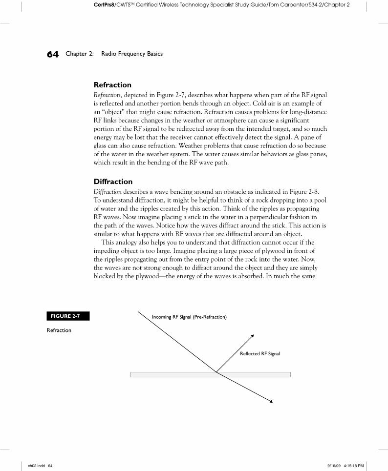
RefractionRefraction, depicted in Figure 2-7, describes what happens when part of the RF signal is reflected and another portion bends through an object. Cold air is an example of an “object” that might cause refraction. Refraction causes problems for long-distance RF links because changes in the weather or atmosphere can cause a significant portion of the RF signal to be redirected away from the intended target, and so much energy may be lost that the receiver cannot effectively detect the signal. A pane of glass can also cause refraction. Weather problems that cause refraction do so because of the water in the weather system. The water causes similar behaviors as glass panes, which result in the bending of the RF wave path.
DiffractionDiffraction describes a wave bending around an obstacle as indicated in Figure 2-8. To understand diffraction, it might be helpful to think of a rock dropping into a pool of water and the ripples created by this action. Think of the ripples as propagating RF waves. Now imagine placing a stick in the water in a perpendicular fashion in the path of the waves. Notice how the waves diffract around the stick. This action is similar to what happens with RF waves that are diffracted around an object.
This analogy also helps you to understand that diffraction cannot occur if the impeding object is too large. Imagine placing a large piece of plywood in front of the ripples propagating out from the entry point of the rock into the water. Now, the waves are not strong enough to diffract around the object and they are simply blocked by the plywood—the energy of the waves is absorbed. In much the same
Incoming RF Signal (Pre-Refraction)
Reflected RF Signal
FIGURE 2-7
Refraction
ch02.indd 64 9/16/09 4:15:18 PM
RF Signal Characteristics 65
CertPrs8/CWTSTM Certified Wireless Technology Specialist Study Guide/Tom Carpenter/534-2/Chapter 2
way, RF waves might not be able to diffract around large obstructions. Much like stronger water waves are more likely to diffract around larger obstacles, stronger RF waves are more likely to diffract around larger obstacles.
One final reality revealed by this analogy of the plywood is the concept of RF shadow. Imagine placing a 2 × 4 in the water instead of the stick or plywood. When you place the stick in the water, you cannot see the shadow created, but the 2 × 4 is large enough to reveal the shadow, but not too large—as the plywood is—to block the wave. Look closely behind the 2 × 4 (or the building shown in Figure 2-8) and you will notice a space where no waves exist. This space is the wave shadow, or on wireless networks, the RF shadow. You will not get acceptable wireless reception in this space.
ScatteringScattering is what happens when the medium the RF wave is traveling through contains objects with dimensions that are small in comparison to the wavelength of the RF signal. Scattering is produced by rough surfaces, small objects, or irregularities
Antenna
Building
New WavefrontDirection
Old WavefrontDirection
RF Shadow
FIGURE 2-8
Diffraction
ch02.indd 65 9/16/09 4:15:19 PM
66 Chapter 2: Radio Frequency Basics
CertPrs8/CWTSTM Certified Wireless Technology Specialist Study Guide/Tom Carpenter/534-2/Chapter 2
in the signal path. Figure 2-9 shows that scattering is a lot like many little reflections. When referred to as reflection, the vast majority of the signal is reflected in the same direction, and when referred to as scattering, many portions of the signal are reflected (scattered) in different directions.
AbsorptionThe final important RF behavior that you must understand is absorption. As noted earlier, absorption is what makes microwaves work and your wireless signal degrade. RF signals can be absorbed by many different objects, including the air through which the signals pass, causing a reduction in signal strength until, eventually, the signal is lost or undetectable. This weakening of signal strength as it travels through space is known as free space path loss. Water is also an excellent signal absorber above the 2 GHz range. This is why the 2.4 GHz range is generally used by microwave ovens. While the RF waves can move through food well, water molecules cannot vibrate fast enough to keep up with the RF waves and so they absorb the energy instead.
It is important to remember that humans are basically moving food (not a pleasant thought, huh?) because we are mostly water. Therefore, the more humans in a space, the more of the RF signal that will be absorbed. Keep this in mind for large convention spaces with low ceilings and large rooms. For this same reason, it is important to remember that most living things have a large saturation of water, including plants and animals, and therefore, heavily forested areas are prime spots for weakened signals in the 2.4 GHz spectrum. The 5 GHz spectrum is impacted by water-based life forms as well, but not as significantly as the 2.4 GHz spectrum. In fact, microwave ovens operate in the 2.4 GHz spectrum for this very reason; the 2.4 GHz waves are absorbed most easily by water.
Incoming RF Signal (Pre-Scattering)
Reflected RF Signals
FIGURE 2-9
Scattering
ch02.indd 66 9/16/09 4:15:20 PM
Basic RF Mathematics 67
CertPrs8/CWTSTM Certified Wireless Technology Specialist Study Guide/Tom Carpenter/534-2/Chapter 2
Polarization and DiversityDue to the nature of RF propagation, engineers have developed concepts and technologies that can help to improve communications in WLANs. The first is a concept known as polarization. The polarization of an antenna may be defined as vertical or horizontal, though you can actually position the antenna at any angle. Sometimes a tilted antenna is best. A vertically polarized antenna is one that is positioned in a vertically upright position. A horizontally polarized antenna is one that is positioned in a horizontal or “fallen over” position. Vertical polarization results in horizontal radiation, and horizontal polarization results in vertical radiation. Read that last sentence again because it is accurate and very important to remember.
The impact of polarization is seen when antennas are not polarized in the same way. For example, if you have an access point with the antennas positioned vertically (vertical polarization) and you have a USB client adapter with the antenna down (horizontal polarization), your connectivity will be less stable and, at greater distances, may even be lost. However, in most cases, due to indoor reflections, the polarization of antennas does not have as great an impact as it does with outdoor links. In outdoor links, the proper polarization of the antennas can make or break the connection.
The second concept or technology engineers have developed is antenna diversity. Diversity helps to solve problems created by multipath. Multipath occurs when the same signal arrives at the receiver after traveling different paths. The signal may be out of phase, and this can result in performance problems.
Simple diversity refers to an implementation of antenna diversity wherein the wireless station simply chooses the best antenna for communications. MIMO diversity is often used to reference the active use of all antennas at the same time.
CERTIFICATION OBJECTIVE 2.03
Basic RF MathematicsTo successfully implement and manage an RF-based network, you must understand the power levels of the RF signal. RF math provides us with a standardized way to communicate the strength, or weakness, of an RF signal at the point of radiation as well as the point of reception.
ch02.indd 67 9/16/09 4:15:20 PM
68 Chapter 2: Radio Frequency Basics
CertPrs8/CWTSTM Certified Wireless Technology Specialist Study Guide/Tom Carpenter/534-2/Chapter 2
You must understand milliwatts and decibels and then move on to learn about dBm and dBi in order to come to grips with RF math. Finally, you can’t work with wireless technology for very long without encountering the phrase signal-to-noise ratio, so you will learn about this as well.
Milliwatts and DecibelsIn much the same way that our ears need a certain volume level to hear sounds, RF antennas require a certain power level to receive signals. In order to ensure the power levels are high enough for operations, you must employ a method to measure the power. The watt is a standard measure of power used in most engineering applications; however, in wireless networking, because lower power levels are used, another measurement is needed in addition to the watt.
A watt is technically defined as one ampere (A) of current at one volt (V). This is also said as “one watt is equal to an ampere multiplied by a volt.” As an analogy, think of a water hose with water passing through it. The pressure on the water line can be compared to the voltage in an electric circuit, and the flow of the water can be compared to the amperes (or current). In perspective, a common nightlight uses about seven watts of power.
You may be wondering why wireless networks use such low power levels and, therefore, require a different measurement method than a watt. To answer that question, think of that seven-watt nightlight. On a clear night, this light could be seen up to 50 miles in all directions. This is why the FCC limits RF signal output in the 2.4 GHz band to just four watts. As with that seven-watt nightlight, a four-watt signal can be sent for miles.
Because a small amount of power is required, we use the term milliwatt to measure most wireless communication power levels. Standard access points, wireless clients, and wireless network devices have output power levels that are commonly between 1 and 100 milliwatts. A milliwatt (represented by “mW”) is 1/1000 of a watt. So 100 mW of output is the same as 1/10 of a watt of output. When you document the
power levels needed to provide the required communication signal strength, you use milliwatts or decibels in most cases.
A decibel is used to represent extremely small numbers in a manageable way. Some receivers are sensitive enough to RF signals that they can receive a signal as small as 0.000000001 watts. Because of the difficulty in grasping such small numbers, the decibel is used to measure these levels of strength.
Decibels are used to measure increases and decreases in signal strength in a manner that is easy to grasp for administrators, technicians, and users alike.
ch02.indd 68 9/16/09 4:15:20 PM
Basic RF Mathematics 69
CertPrs8/CWTSTM Certified Wireless Technology Specialist Study Guide/Tom Carpenter/534-2/Chapter 2
Decibels (dB) are based on a logarithmic relationship to the literal or linear power measurement of a watt. This is a complex way of saying that decibels allow you to represent large (and small) numbers with numbers you can wrap your mind around. The most important thing for you to remember is the rule of 10s and 3s in RF math. Here’s how it works:
–3 dB = half the power in mW+3 dB = double the power in mW–10 dB = one tenth the power in mW+10 dB = ten times the power in mW
Using creative combinations of 10s and 3s, you can usually calculate the output or input power levels of any wireless system. You use this most frequently when calculating gains and losses based on equipment used to form an intentional radiator (all of the equipment, cables, and connectors leading up to, but not including, the output antenna in an RF system) or when determining the actual equivalent isotropically radiated power (EIRP) output, which is the actual output from an antenna, including calculations of the intentional radiator and any antenna gains or losses.
As an example, imagine you have a wireless access point with 30 mW of output power connected to a cable with 3 dB of loss and feeding into an amplifier with 9 dB of gain and then into another cable with 3 dB of loss and finally output through an antenna with 7 dB of gain. What is the actual output power (EIRP) of this system? The answer can be found by using the 10s and 3s of RF math as follows:
30 mW – 3 dB for the cable = 15 mW (divide × 2 one time)15 mW + 9 dB for the amplifier = 120 mW (multiply × 2 three times)120 mW – 3 dB for the second cable = 60 mW (divide × 2 one time)60 mW + 7 dB for the antenna = 300 mW
This is where the creative use of the 10s and 3s comes into play. The last calculation of 60 mW + 7 dB might have seemed impossible. However, by multiplying the 60 mW times 10 (60 mW + 10 dB), you arrive at 600 mW. What is 7 from 10? The answer is 3. You now subtract 3 dB from the 600 mW and arrive at 300 mW of EIRP. In other words, because dB calculations are additive, +7 dB is the same as +10 dB/–3dB. This trick allows you to calculate more complex power level scenarios more easily.
Another way to perform the same calculation is to add up all the dB gains and losses and then recalculate the signal strength just once. Follow me on this. We had 3 dB of loss in the first cable, and that gives us a negative 3. We had 9 dB of gain
ch02.indd 69 9/16/09 4:15:20 PM
70 Chapter 2: Radio Frequency Basics
CertPrs8/CWTSTM Certified Wireless Technology Specialist Study Guide/Tom Carpenter/534-2/Chapter 2
in the amplifier, and that gives us a positive 6. We had another 3 dB of loss in the second cable, and that gives us a positive 3. Finally we had 7 dB of passive gain in the antenna, and this gives us a positive 10. What is 30 mW × 10? The answer is the same as we reached with the step-by-step mW calculations earlier: 300 mW. Here is a method for representation of this calculation:
–3 dB + 9 dB + –3 dB + 7 dB = 10 dB30 mW + 10 dB = 30 mW × 1030 mW × 10 = 300 mW
dBm vs. dBiOther common measurements you will see in the area of wireless technology include dBm and dBi. The reference point that relates the logarithmic dB scale to the linear watt scale is 1 mW = 0 dBm. Because dBm is linked to the linear milliwatts scale, it is an absolute reference of power. The m in dBm simply stands for milliwatts. This means that when wireless product packaging states that a device provides up to 20 dBm of output power, it is promising a specific level of output power (in this case it is promising approximately 100 mW of output power).
Remember that 1 mW is equal to 0 dBm, so a 20 dBm product would be equal to 1 mW × 10 × 10, or 100 mW. Likewise, a 9 dBm product would be equal to 1 mW × 2 × 2 ×2, or 8 mW. dBm is a reference to the relationship between decibels and linear watts.
The second term, dBi, is used to reference the increase in power in a certain direction by an antenna. The i in dBi stands for isotropic. This simply means that the change in power provided by the antenna is calculated against what an isotropic radiator would produce. An isotropic radiator is a theoretical transmitter that propagates RF energy exactly equally in all directions. No such antenna exists, as all antennas propagate more of their energy in one or more directions than in others, which results in a gain in the output power according to the directionality of the antenna. Think of this, again, as placing your thumb over a portion of the opening of a water hose. The same pressure is being applied, but the possible “direction” of the pressure is reduced, causing the water to spray farther.
If an antenna is referenced as a 6 dBi antenna, it means that it quadruples (remember, +3 dB + 3 dB = × 2 × 2) the output power in the direction of the antenna. If 100 mW of power is fed into the antenna, the output power is estimated at 400 mW in the direction of the antenna.
ch02.indd 70 9/16/09 4:15:21 PM
Basic RF Mathematics 71
CertPrs8/CWTSTM Certified Wireless Technology Specialist Study Guide/Tom Carpenter/534-2/Chapter 2
SNR: Signal-to-Noise RatioOne final measurement used to determine the strength and quality of an RF signal is the signal-to-noise ratio (SNR or S/N ratio). The SNR does not measure the power of the signal by itself in absolute or relative terms like dB or dBm does, but it is used to measure the signal power compared to the power of the noise in the environment. A higher SNR indicates a better signal, as the signal is much “louder” than the noise.
Returning to the human hearing analogy, if you are in a quiet room, another person could whisper to you and you could hear her easily. However, in a football stadium watching the Super Bowl, the person will have to shout for you to hear her over the noise. The same basic concepts apply to wireless networking.
The RF noise in the environment is often referred to as the noise floor. Many programs give you the ability to view the SNR in your environment. One of the most commonly used tools is NetStumbler, which is shown in Figure 2-10. Determining the SNR in areas of desired coverage is an important part of wireless network implementation.
To calculate the signal-to-noise ratio, calculate the difference between the power levels of the signal and the power levels of the noise. For example, a signal power level of –55 dBm and a noise power level of –97 dBm gives you an SNR of 42. This is better than an SNR of 17, which is the result of the same noise level with a signal level of –80 dBm.
FIGURE 2-10
Signal-to-noise ratio in NetStumbler
ch02.indd 71 9/16/09 4:15:21 PM
72 Chapter 2: Radio Frequency Basics
CertPrs8/CWTSTM Certified Wireless Technology Specialist Study Guide/Tom Carpenter/534-2/Chapter 2
CERTIFICATION OBJECTIVE 2.04
RF Physical Layer TechnologiesThere are many different technologies that utilize RF communications. The major differences among them are the frequencies and encoding techniques they use. While more information about each technology is provided in the next chapter—specifically DSSS, OFDM, and FHSS—a brief overview will be helpful here. These technologies include the following:
■ DSSS
■ HR/DSSS
■ OFDM
■ FHSS
■ Infrared
■ MIMO
DSSS and HR/DSSSDirect sequence spread spectrum (DSSS) is the technology used in 802.11 and 802.11b devices, providing data rates of 1, 2, 5.5, and 11 Mbps. Because backward compatibility is provided, 802.11b devices operating at 5.5 or 11 Mbps can communicate with 802.11 devices running at 1 or 2 Mbps. Of course, these devices are limited to the speed of the slower device in the link. The 802.11 and 802.11b standards specify that DSSS is to be used in the 2.4 GHz spectrum of RF frequencies.
The original 802.11 standard specified DSSS to operate in the 2.4 GHz spectrum at data rates of 1 or 2 Mbps. The 802.11b amendment specified High Rate/DSSS (HR/DSSS) to operate in the 2.4 GHz spectrum at data rates of 1, 2, 5.5, or 11 Mbps. The original PHY (remember, physical layer) is known as the DSSS PHY, and the 802.11b amendment introduced the HR/DSSS PHY.
DSSS systems use assigned channels for communications. These channels are blocks of frequency space or frequency ranges. Unlike frequency hopping spread spectrum systems, DSSS systems are configured to use the same frequencies permanently, so frequencies do not change during communications. An 802.11b channel is 22 MHz wide.
ch02.indd 72 9/16/09 4:15:21 PM
RF Physical Layer Technologies 73
CertPrs8/CWTSTM Certified Wireless Technology Specialist Study Guide/Tom Carpenter/534-2/Chapter 2
OFDM802.11a utilizes a different technology for communications known as orthogonal frequency division multiplexing, or OFDM to avoid the mouthful. OFDM is also used in 802.11g with modifications for backward compatibility with 802.11b and 802.11 HR/DSSS and DSSS respectively. Unlike DSSS, which uses the full channel as a single “pipe,” OFDM divides a channel into subcarriers or subchannels and sends data streams on these “separate pipes.” This provides for greater resistance to multipath interference and allows for greater bandwidth. 802.11a operates in the 5 GHz spectrum, and 802.11g operates in the 2.4 GHz spectrum. The PHY introduced by 802.11a is technically known as OFDM, and the PHY introduced by 802.11g is technically known as ERP.
OFDM channels, as implemented in 802.11a, are 20 MHz wide and are nonoverlapping. ERP channels, as implemented in 802.11g, are 22 MHz wide in order to maintain backward compatibility with HR/DSSS and DSSS.
FHSSFrequency hopping spread spectrum (FHSS) is another spread spectrum technology, such as DSSS, that is used by older 802.11 devices and Bluetooth devices as well as some RFID units. FHSS is limited to 1 or 2 Mbps in the 802.11 specification. As you might guess by the name, FHSS systems hop from one frequency to another during communications. This helps to avoid the problems caused by narrow-band interference. FHSS is no longer covered on the CWTS exam, but it is a widely used technology due to the large number of Bluetooth devices. Bluetooth devices are not compatible with 802.11, but they communicate in the 2.4 GHz spectrum and this may result in interference issues.
You are not likely to be tested on details related to the original DSSS, but it is good to know about and understand, since you may encounter these
devices in existing installations. Thankfully, the vast majority of installations are using HR/DSSS or higher today.
ch02.indd 73 9/16/09 4:15:21 PM
74 Chapter 2: Radio Frequency Basics
CertPrs8/CWTSTM Certified Wireless Technology Specialist Study Guide/Tom Carpenter/534-2/Chapter 2
InfraredThe 802.11 standard includes a PHY (physical layer) specification for infrared communications. However, because of lack of interest, this layer has not been implemented. You might question this if you have a laptop or PDA that uses an infrared port, but that port is most likely designed according to standards set forth by the Infrared Data Association (IrDA) and not the 802.11 PHY standard. The CWTS exam does not test your knowledge of the nonimplemented Infrared PHY.
MIMOMultiple input/multiple output (MIMO, pronounced “my-moe”) devices allow the use of more than one antenna at the same time by using multiple data streams in the same channel via “smart antennas.” MIMO-based networks can help in overcoming multipath problems (the result of the signal being reflected off different objects in the environment) and increasing the speed of communications. Many devices by such companies as Belkin, Cisco, and others provide this technology.
MIMO is part of the new 802.11n standard for high-throughput communications. The 802.11n task group that was formed in January 2004 aimed at creating a wireless standard with theoretical throughputs of up to 540 Mbps. 802.11n uses a combination of MIMO and OFDM technologies and actually ended up providing a maximum data rate of 600 Mbps with four antennas on each end of the link and 40 MHz channels. The PHY introduced by the 802.11n amendment is technically called the High Throughput (HT) PHY. This PHY may operate in the 2.4 GHz spectrum, the 5 GHz spectrum, or both, and it may use either 20 or 40 MHz channels. In order to achieve the highest rates offered by 802.11n, you must use 40 MHz channels and you must use 4 × 4 configurations (four transmit and receive radio chains at each end of the link).
CERTIFICATION SUMMARYThis chapter introduced concepts related to RF-based communications. You learned about the factors that impact the range and speed of WLANs. You also learned how to calculate and measure the signal strength of wireless links. Basic RF antenna concepts were also introduced, including polarization and simple diversity. Finally, you reviewed the basic features of the different Physical layer technologies used in WLANs. You will learn many more details about these Physical layers in Chapter 3.
ch02.indd 74 9/16/09 4:15:21 PM
Two-Minute Drill 75
CertPrs8/CWTSTM Certified Wireless Technology Specialist Study Guide/Tom Carpenter/534-2/Chapter 2
TWO-MINUTE DRILL
RF Range and Speed Factors
❑ Line of sight (LOS) is most important for outdoor long-distance links.
❑ RF LOS must factor in the first Fresnel zone and ensure that at least 60 percent of this zone is clear.
❑ For improved stability and reduced maintenance, many engineers choose to ensure an 80 percent clearance of the first Fresnel zone.
❑ Baby monitors, spread spectrum phones, and microwaves may cause interfer-ence with WLANs operating in the 2.4 GHz spectrum.
❑ Motors and other electric devices may generate unintentional RF noise.
RF Signal Characteristics
❑ When the strength of a signal increases, this is called gain.
❑ When the strength of a signal decreases, this is called loss.
❑ Amplification causes gain.
❑ Attenuation causes loss.
❑ Wires, connectors, and devices in the path from the RF generator to the antenna may cause loss.
❑ Free space path loss occurs as RF waves travel through the air.
Basic RF Mathematics
❑ An increase of 3 dB doubles the signal strength in mW.
❑ A decrease of 3 dB halves the signal strength in mW.
❑ An increase of 10 dB multiplies the signal strength in mW by a factor of 10.
❑ A decrease of 10 dB divides the signal strength in mW by a factor of 10.
❑ A mW is 1/1000 of a watt.
RF Physical Layer Technologies
❑ HR/DSSS is a PHY that provides up to 11 Mbps and operates in the 2.4 GHz spectrum.
✓
ch02.indd 75 9/16/09 4:15:22 PM
76 Chapter 2: Radio Frequency Basics
CertPrs8/CWTSTM Certified Wireless Technology Specialist Study Guide/Tom Carpenter/534-2/Chapter 2
❑ OFDM is a PHY that provides up to 54 Mbps and operates in the 5 GHz spectrum.
❑ ERP is a PHY that provides up to 54 Mbps and operates in the 2.4 GHz spectrum.
❑ HT is a PHY that provides up to 600 Mbps and operates in either the 2.4 GHz spectrum or the 5 GHz spectrum or both.
ch02.indd 76 9/16/09 4:15:22 PM
Self Test 77
CertPrs8/CWTSTM Certified Wireless Technology Specialist Study Guide/Tom Carpenter/534-2/Chapter 2
SELF TESTThe following questions will help you measure your understanding of the material presented in this chapter. Read all the choices carefully because there might be more than one correct answer. Choose all correct answers for each question.
RF Range and Speed Factors
1. Which of the following devices are likely to cause RF interference for 2.4 GHz WLANs? (Choose all that apply.)
A. Cell phones B. Baby monitors C. Microwave ovens D. Televisions
2. Which one of the following devices is not likely to cause interference when implementing a new 802.11g (ERP) WLAN?
A. Close proximity 802.11b WLANs B. Close proximity 802.11a WLANs C. Baby monitors D. Microwave ovens
3. What is the maximum allowed percentage of the first Fresnel zone that may be blocked while still maintaining communications?
A. 80 percent B. 60 percent C. 20 percent D. 40 percent
4. You are implementing a WLAN within a building. The building is less than 2000 square feet, and there are very few internal walls. How much of the first Fresnel zone should have clearance for this network to operate smoothly?
A. Eighty percent of the first Fresnel zone should be clear. B. The Fresnel zones are not as important for indoor networks due to the propagation behaviors
of WLAN signals. C. Sixty percent of the first Fresnel zone should be clear. D. One hundred percent of the first Fresnel zone must be clear for indoor WLANs.
ch02.indd 77 9/16/09 4:15:22 PM
78 Chapter 2: Radio Frequency Basics
CertPrs8/CWTSTM Certified Wireless Technology Specialist Study Guide/Tom Carpenter/534-2/Chapter 2
5. Which of the following is a valid definition of Fresnel zones? A. Ellipse-shaped areas around the visual line of sight in an RF link B. Parallel lines that run along the visual line of sight in an RF link C. The donut-shaped area around an antenna that provides WLAN coverage D. The width of the transmitting RF beam at the point of half power
RF Signal Characteristics
6. An access point is generating 50 mW of output power. The cables and connectors leading up to the antenna introduce 6 dB of loss. The signal strength has weakened. What is the difference between the original signal power level and the resulting power level called when the signal is weakened?
A. Gain B. Loss C. Impedance D. Reflection
7. What causes loss? A. Amplification B. Attenuation C. Augmentation D. Aggravation
8. You have implemented a WLAN link between two buildings that are about 180 feet apart. The space between the buildings is completely free of objects. The antennas are mounted high enough that the first Fresnel zone has zero blockage. The link still loses power between the transmitting and receiving antenna. What is causing this?
A. Diffraction B. Reflection C. Free space path loss D. Absorption
Basic RF Mathematics
9. An access point generates a 100 mW signal. The cables and connectors leading up the antenna cause 13 dB of loss. The antenna introduces 12 dB of gain. What is the signal strength, in mW, in the direction of the intended propagation?
A. 80 mW B. 125 mW
ch02.indd 78 9/16/09 4:15:23 PM
Lab Question 79
CertPrs8/CWTSTM Certified Wireless Technology Specialist Study Guide/Tom Carpenter/534-2/Chapter 2
C. 100 mW D. 5 mW
RF Physical Layer Technologies
10. Which PHY was introduced in the 802.11b amendment and what is the channel width used by this PHY?
A. HR/DSSS with 20 MHz channels B. OFDM with 16 MHz channels C. HR/DSSS with 22 MHz channels D. OFDM with 25 MHz channels
11. OFDM was first implemented in the 802.11 standard as part of what amendment? A. 802.11a B. 802.11b C. 802.11g D. 802.11n
12. Which PHYs utilize the 2.4 GHz license-free ISM bands? (Choose all that apply.) A. ERP B. HR/DSSS C. HT D. OFDM
LAB QUESTIONYou are implementing a WLAN for a small business. The company leases space in an office building. Surrounding businesses already have WLANs, and they are consuming all of the channels in the 2.4 GHz spectrum. Your client will have only five users on the network, and they will browse the Internet, check e-mail, print documents, and store standard office documents on a file server. The owner says that she wants to play nicely with her neighbors, but she also wants the latest and greatest solution. Which technology will you implement for your client and why?
ch02.indd 79 9/16/09 4:15:23 PM
80 Chapter 2: Radio Frequency Basics
CertPrs8/CWTSTM Certified Wireless Technology Specialist Study Guide/Tom Carpenter/534-2/Chapter 2
SELF TEST ANSWERS
RF Range and Speed Factors
1. Which of the following devices are likely to cause RF interference for 2.4 GHz WLANs? (Choose all that apply.)
A. Cell phones B. Baby monitors C. Microwave ovens D. Televisions
®✓ B and C are correct. Both the baby monitors and the microwave ovens are likely to generate 2.4 GHz signals or noise and may cause interference with a WLAN. ®̊ A and D are incorrect. Cell phones operate in licensed frequencies, and televisions do not usually generate RF noise or signals in the 2.4 GHz spectrum with enough intensity to cause interference.
2. Which one of the following devices is not likely to cause interference when implementing a new 802.11g (ERP) WLAN?
A. Close proximity 802.11b WLANs B. Close proximity 802.11a WLANs C. Baby monitors D. Microwave ovens
®✓ B is correct. 802.11a WLANs use the 5 GHz bands and will not interfere with 802.11g WLANs. ®̊ A, C, and D are incorrect. 802.11b WLANs operate in the same 2.4 GHz band and may interfere with 802.11g WLANs. Baby monitors and microwave ovens may cause interference as well.
3. What is the maximum allowed percentage of the first Fresnel zone that may be blocked while still maintaining communications?
A. 80 percent B. 60 percent C. 20 percent D. 40 percent
ch02.indd 80 9/16/09 4:15:23 PM
Self Test Answers 81
CertPrs8/CWTSTM Certified Wireless Technology Specialist Study Guide/Tom Carpenter/534-2/Chapter 2
®✓ D is correct. The key to the question is that it asks for the percentage that may be blocked and not that which must be clear. Since 60 percent must be clear, 40 percent may be blocked. ®̊ A, B, and C are incorrect. If 80 or 60 percent of the first Fresnel zone is blocked, connections will be impossible or unstable. Ideally only 20 percent of the first Fresnel zone will be blocked, but the question asked for the maximum allowed percentage of blockage.
4. You are implementing a WLAN within a building. The building is less than 2000 square feet, and there are very few internal walls. How much of the first Fresnel zone should have clearance for this network to operate smoothly?
A. Eighty percent of the first Fresnel zone should be clear. B. The Fresnel zones are not as important for indoor networks due to the propagation
behaviors of WLAN signals. C. Sixty percent of the first Fresnel zone should be clear. D. One hundred percent of the first Fresnel zone must be clear for indoor WLANs.
®✓ B is correct. Indoor WLANs are not as impacted by first Fresnel zone issues, since reflection, refraction, and diffraction help the signals to propagate to many areas of the indoor facility. ®̊ A, C, and D are incorrect. All of these answers are incorrect, since the Fresnel zones are not usually considered for coverage-based WLANs as opposed to bridge links.
5. Which of the following is a valid definition of Fresnel zones? A. Ellipse-shaped areas around the visual line of sight in an RF link B. Parallel lines that run along the visual line of sight in an RF link C. The donut-shaped area around an antenna that provides WLAN coverage D. The width of the transmitting RF beam at the point of half power
®✓ A is correct. A Fresnel zone, named for physicist Augustin-Jean Fresnel, is one of a (theoretically infinite) number of concentric ellipsoids that define volumes in the radiation pattern of an RF link. ®̊ B, C, and D are incorrect. These definitions are not proper definitions of Fresnel zones.
RF Signal Characteristics
6. An access point is generating 50 mW of output power. The cables and connectors leading up to the antenna introduce 6 dB of loss. The signal strength has weakened. What is the difference between the original signal power level and the resulting power level called when the signal is weakened?
A. Gain B. Loss
ch02.indd 81 9/16/09 4:15:24 PM
82 Chapter 2: Radio Frequency Basics
CertPrs8/CWTSTM Certified Wireless Technology Specialist Study Guide/Tom Carpenter/534-2/Chapter 2
C. Impedance D. Reflection
®✓ B is correct. This difference in signal strength is called loss when the resulting signal is weaker than the original signal. ®̊ A, C, and D are incorrect. The difference is known as gain when the resulting signal is stronger than the original signal. Impedance is a reference to the resistance imposed by a cable or connector. The impedances of different cables and connectors in a system should match. Reflection is what occurs when RF waves hit large smooth surfaces.
7. What causes loss? A. Amplification B. Attenuation C. Augmentation D. Aggravation
®✓ B is correct. Attenuation causes loss. ®̊ A, C, and D are incorrect. Amplification causes gain. Augmentation may cause gain, but it is not the normal term. Aggravation just causes, well, aggravation.
8. You have implemented a WLAN link between two buildings that are about 180 feet apart. The space between the buildings is completely free of objects. The antennas are mounted high enough that the first Fresnel zone has zero blockage. The link still loses power between the transmitting and receiving antenna. What is causing this?
A. Diffraction B. Reflection C. Free space path loss D. Absorption
®✓ C is correct. Free space path loss impacts any link regardless of Fresnel zone clearance. Free space path loss occurs more because of the spreading of the wave front than the absorption of energy by the moisture in the air. Significant precipitation levels would be needed to absorb measurable RF energy in this short link. ®̊ A, B, and D are incorrect. Since the path between the two antennas has zero Fresnel zone blockage, no diffractions or reflections should have an impact on the signal strength at the receiver. There are no materials between the transmitter and the receiver that could absorb significant RF energy.
ch02.indd 82 9/16/09 4:15:24 PM
Self Test Answers 83
CertPrs8/CWTSTM Certified Wireless Technology Specialist Study Guide/Tom Carpenter/534-2/Chapter 2
Basic RF Mathematics
9. An access point generates a 100 mW signal. The cables and connectors leading up the antenna cause 13 dB of loss. The antenna introduces 12 dB of gain. What is the signal strength, in mW, in the direction of the intended propagation?
A. 80 mW B. 125 mW C. 100 mW D. 5 mW
®✓ A is correct. 13 dB of loss plus 12 dB of gain equals 1 dB of loss. To calculate this, we take the original 100 mW and divide by 10 to get 10 mW. Next we multiply by 2 three times (10 – 3 × 3 = 1; we’re using the rule of 10s and 3s) to get 80 mW. ®̊ B, C, and D are incorrect. These values are simply incorrect.
RF Physical Layer Technologies
10. Which PHY was introduced in the 802.11b amendment and what is the channel width used by this PHY?
A. HR/DSSS with 20 MHz channels B. OFDM with 16 MHz channels C. HR/DSSS with 22 MHz channels D. OFDM with 25 MHz channels
®✓ C is correct. HR/DSSS is the PHY that was introduced in 802.11b and it uses 22 MHz channels. ®̊ A, B and D are incorrect. While HR/DSSS was the PHY introduced in 802.11b, it uses 22 MHz channels instead of 20 MHz channels. OFDM was introduced in 802.11a and uses 20 MHz channels.
11. OFDM was first implemented in the 802.11 standard as part of what amendment? A. 802.11a B. 802.11b C. 802.11g D. 802.11n
®✓ A is correct. ®̊ B, C, and D are incorrect. 802.11b introduced the HR/DSSS PHY. 802.11g introduced the ERP PHY. While 802.11g implements OFDM, the PHY is called either ERP or ERP-OFDM and not simply OFDM. 802.11n implements OFDM, but it is called HT in the 11n amendment, and 11n was not the first amendment to introduce OFDM.
ch02.indd 83 9/16/09 4:15:24 PM
84 Chapter 2: Radio Frequency Basics
CertPrs8/CWTSTM Certified Wireless Technology Specialist Study Guide/Tom Carpenter/534-2/Chapter 2
12. Which PHYs utilize the 2.4 GHz license-free ISM bands? (Choose all that apply.) A. ERP B. HR/DSSS C. HT D. OFDM
®✓ A, B, and C are correct. ERP, HR/DSSS, and HT PHYs may all operate in the 2.4 GHz bands. HT PHYs may also operate in the 5 GHz U-NII bands. ®̊ D is incorrect. OFDM (802.11a) operates only in the 5 GHz U-NII bands.
LAB ANSWERYou are implementing a WLAN for a small business. The company leases space in an office building. Surrounding businesses already have WLANs, and they are consuming all of the channels in the 2.4 GHz spectrum. Your client will have only five users on the network, and they will browse the Internet, check e-mail, print documents, and store standard office documents on a file server. The owner says that she wants to play nicely with her neighbors, but she also wants the latest and greatest solution. Which technology will you implement for your client and why?
The following represents one possible solution to the lab. Your answer may vary.
Since the client wants the latest and greatest solution, this scenario demands the implementation of 802.11n (the HT PHY). You will need to select HT devices that can operate in the 5 GHz spectrum. This decision will allow the client to play nicely with the neighboring businesses, but it will also allow the network to perform at the highest level available today. A single 802.11n access point or wireless router should easily serve the needs referenced for the five users of the network.


![Mapua-cwts Program Module 1 [Ay11-12]](https://static.documents.pub/doc/80x56/544b4473b1af9f744f8b4de9/mapua-cwts-program-module-1-ay11-12.jpg)


