Application Note Radio Frequency Coverage Mapping with Anritsu’s Remote Spectrum Monitor MS27101A, Vision ™ MX280001A Software, and TRX NEON ® Signal Mapper MA8100A The ideal combination for indoor/outdoor, multi-frequency radio coverage mapping measurements Application Description In the past, radio coverage mapping requirements were driven by the need to verify a single transmitter channel to see where there was sufficient radio coverage and where coverage holes were located. However, today there are many applications where radio coverage must be verified for multiple channels across a very wide frequency range. A good example is how various commercial cellular operators must verify reliable service and good throughput rates of indoor distributed antenna systems (DAS) found in many public spaces, such as shopping malls, airports, or sport stadiums. In many cases, multiple channels on multiple frequencies are used and they would ideally test all of these frequencies in parallel to maximize efficiency. Another example would be verifying the interaction of outdoor-to-indoor coverage for TETRA-based, in-building coverage systems and the resulting interferences. The ideal test system should be able to track multiple frequencies by either walking or driving a given area. This application note will explain how to build and use a radio frequency coverage mapping test system utilizing Anritsu's Remote Spectrum Monitor MS27101A (Figure 1), Vision MX280001A software, and TRX NEON Signal Mapper MA8100A solutions. Hardware and Usage Requirements Channel scanner functionality is needed in order to scan through a defined set of frequency channels. For coverage mapping applications, it is important that the scanning speed is fast enough to capture all of the desired channels while seamlessly following the movements of the person making the measurements. The Remote Spectrum Monitor MS27101A offers outstanding sweep speeds even for smaller resolution (RBW) or video bandwidths (VBW), which is important for narrowband communications standards such as analog FM, P25, TETRA, DMR, and dPMR. For instance, dPMR uses 6.25 kHz channels, P25 and DMR use 12.5 kHz channels, and TETRA channels are usually separated into 25 kHz blocks within a 5 MHz frequency segment. Figure 1: Anritsu Remote Spectrum Monitor MS27101A Figure 2: TRX NEON Signal Channel Scanner configuration menu and belt-worn bluetooth tracking unit
Transcript
Application Note
Radio Frequency Coverage Mapping with Anritsu’s Remote Spectrum Monitor MS27101A, Vision™ MX280001A Software, and TRX NEON® Signal Mapper MA8100AThe ideal combination for indoor/outdoor, multi-frequency radio coverage mapping measurements
Application DescriptionIn the past, radio coverage mapping requirements were driven by the need to verify a single transmitter channel to see where there was sufficient radio coverage and where coverage holes were located. However, today there are many applications where radio coverage must be verified for multiple channels across a very wide frequency range. A good example is how various commercial cellular operators must verify reliable service and good throughput rates of indoor distributed antenna systems (DAS) found in many public spaces, such as shopping malls, airports, or sport stadiums. In many cases, multiple channels on multiple frequencies are used and they would ideally test all of these frequencies in parallel to maximize efficiency. Another example would be verifying the interaction of outdoor-to-indoor coverage for TETRA-based, in-building coverage systems and the resulting interferences. The ideal test system should be able to track multiple frequencies by either walking or driving a given area.
This application note will explain how to build and use a radio frequency coverage mapping test system utilizing Anritsu's Remote Spectrum Monitor MS27101A (Figure 1), Vision MX280001A software, and TRX NEON Signal Mapper MA8100A solutions.
Hardware and Usage RequirementsChannel scanner functionality is needed in order to scan through a defined set of frequency channels. For coverage mapping applications, it is important that the scanning speed is fast enough to capture all of the desired channels while seamlessly following the movements of the person making the measurements. The Remote Spectrum Monitor MS27101A offers outstanding sweep speeds even for smaller resolution (RBW) or video bandwidths (VBW), which is important for narrowband communications standards such as analog FM, P25, TETRA, DMR, and dPMR. For instance, dPMR uses 6.25 kHz channels, P25 and DMR use 12.5 kHz channels, and TETRA channels are usually separated into 25 kHz blocks within a 5 MHz frequency segment.
Figure 2: TRX NEON Signal Channel Scanner configuration menu and belt-worn bluetooth tracking unit
2
The Anritsu TRX NEON Signal Mapper MA8100A is available for indoor/outdoor single- and multi-channel radio coverage mapping. This solution enables the users to gather channel power and signal quality results by simply walking through an area of interest, as well as see colored breadcrumb trails that indicate the power level and walking path. The TRX NEON Signal Mapper application allows for the definition of multiple frequency sets that are individually defined by center frequency, SPAN, RBW, and desired reference level.
For the measurements taken in this application note, all required hardware was either hand-carried or put into a back pack. The minimum hardware requirements are:
• Anritsu Remote Spectrum Monitor (RSM) MS27101A with Option 407 and 486• Anritsu TRX NEON Signal Mapper MA8100A• Android phone or tablet running Android version 5 (Lollipop) or higher• 12V DC power supply with a minimum capacity of 20,000 mAh• Wi-Fi router capable of Client Mode operation• Antenna for your frequency band of interest
Configuration of TP-Link RouterThe Android device used in this example is a Samsung Galaxy S7 phone. The phone’s cellular service and Wi-Fi hotspot feature were used to access the internet. To do this, the TP-Link router must be setup. The procedure below does not go into the exact details, so please consult your router’s user manual for exact setup procedures.
1. Set router to operate in “Client Mode”. In this mode, the router will connect to the phone’s hotspot for internet access.
2. Connect the router to the Android phone. Depending on your phone, you can select either the 2.4 or 5 GHz wireless network. You must enable the wireless hotspot of your phone. You can then set the router to scan for and connect to it.
3
3. Setup the router’s IP address to be on the same subnet as the phone. In the case of Samsung phones, their default IP address is 192.168.43.1, so setup the TP-Link router’s IP address on the LAN port to be 192.168.43.99.
4. The router’s wired LAN port must be set to be a DHCP server with the IP address range in the same subnet as the IP address of the phone. It is recommended that you set the DHCP Start and End IP Addresses to 192.168.43.199 so that the RSM unit is set to this known IP address.
5. Please note that the Remote Spectrum Monitor MS27101A must be set to either use a static IP of 192.168.43.199 or obtain an IP address from the router using DHCP.
For details on setting up the Remote Spectrum Monitor MS27101A IP address, reference the Remote Spectrum Monitor MS27101A Confirguration Quick Start Guide online.
4
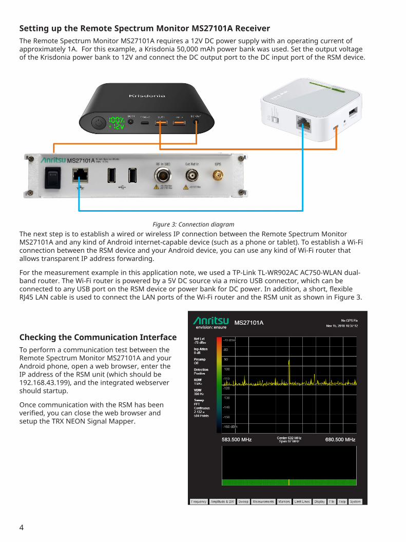
Setting up the Remote Spectrum Monitor MS27101A ReceiverThe Remote Spectrum Monitor MS27101A requires a 12V DC power supply with an operating current of approximately 1A. For this example, a Krisdonia 50,000 mAh power bank was used. Set the output voltage of the Krisdonia power bank to 12V and connect the DC output port to the DC input port of the RSM device.
The next step is to establish a wired or wireless IP connection between the Remote Spectrum Monitor MS27101A and any kind of Android internet-capable device (such as a phone or tablet). To establish a Wi-Fi connection between the RSM device and your Android device, you can use any kind of Wi-Fi router that allows transparent IP address forwarding.
For the measurement example in this application note, we used a TP-Link TL-WR902AC AC750-WLAN dual-band router. The Wi-Fi router is powered by a 5V DC source via a micro USB connector, which can be connected to any USB port on the RSM device or power bank for DC power. In addition, a short, flexible RJ45 LAN cable is used to connect the LAN ports of the Wi-Fi router and the RSM unit as shown in Figure 3.
Checking the Communication InterfaceTo perform a communication test between the Remote Spectrum Monitor MS27101A and your Android phone, open a web browser, enter the IP address of the RSM unit (which should be 192.168.43.199), and the integrated webserver should startup.
Once communication with the RSM has been verified, you can close the web browser and setup the TRX NEON Signal Mapper.
Figure 3: Connection diagram
5
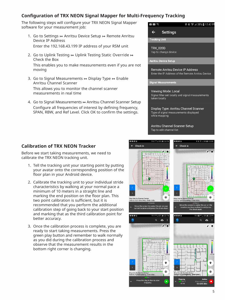
Configuration of TRX NEON Signal Mapper for Multi-Frequency TrackingThe following steps will configure your TRX NEON Signal Mapper software for your measurement job:
1. Go to Settings ↦ Anritsu Device Setup ↦ Remote Anritsu Device IP Address
Enter the 192.168.43.199 IP address of your RSM unit
2. Go to Uplink Testing ↦ Uplink Testing Static Override ↦ Check the Box
This enables you to make measurements even if you are not moving
3. Go to Signal Measurements ↦ Display Type ↦ Enable Anritsu Channel Scanner
This allows you to monitor the channel scanner measurements in real time
4. Go to Signal Measurements ↦ Anritsu Channel Scanner Setup Configure all frequencies of interest by defining frequency,
SPAN, RBW, and Ref Level. Click OK to confirm the settings.
Calibration of TRX NEON TrackerBefore we start taking measurements, we need to calibrate the TRX NEON tracking unit.
1. Tell the tracking unit your starting point by putting your avatar onto the corresponding position of the floor plan in your Android device.
2. Calibrate the tracking unit to your individual stride characteristics by walking at your normal pace a minimum of 10 meters in a straight line and marking the end position on the floor plan. This two point calibration is sufficient, but it is recommended that you perform the additional calibration step of going back to your start position and marking that as the third calibration point for better accuracy.
3. Once the calibration process is complete, you are ready to start taking measurements. Press the green play button and remember to walk normally as you did during the calibration process and observe that the measurement results in the bottom right corner is changing.
6
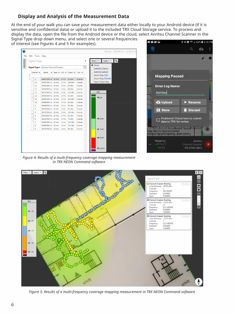
Display and Analysis of the Measurement Data
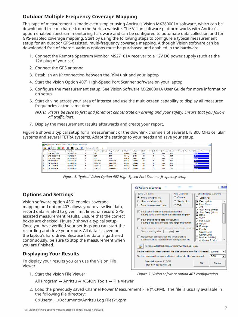
At the end of your walk you can save your measurement data either locally to your Android device (if it is sensitive and confidential data) or upload it to the included TRX Cloud Storage service. To process and display the data, open the file from the Android device or the cloud, select Anritsu Channel Scanner in the Signal Type drop down menu, and select one or several frequencies of interest (see Figures 4 and 5 for examples).
Figure 4: Results of a multi-frequency coverage mapping measurement in TRX NEON Command software
Figure 5: Results of a multi-frequency coverage mapping measurement in TRX NEON Command software
7
Outdoor Multiple Frequency Coverage MappingThis type of measurement is made even simpler using Anritsu's Vision MX280001A software, which can be downloaded free of charge from the Anritsu website. The Vision software platform works with Anritsu's option-enabled spectrum monitoring hardware and can be configured to automate data collection and for GPS-enabled coverage mapping. Start by using the following steps to configure a typical measurement setup for an outdoor GPS-assisted, multi-frequency coverage mapping. Although Vision software can be downloaded free of charge, various options must be purchased and enabled in the hardware.
1. Connect the Remote Spectrum Monitor MS27101A receiver to a 12V DC power supply (such as the 12V plug of your car)
2. Connect the GPS antenna
3. Establish an IP connection between the RSM unit and your laptop
4. Start the Vision Option 4071 High-Speed Port Scanner software on your laptop
5. Configure the measurement setup. See Vision Software MX280001A User Guide for more information on setup.
6. Start driving across your area of interest and use the multi-screen capability to display all measured frequencies at the same time.
NOTE: Please be sure to first and foremost concentrate on driving and your safety! Ensure that you follow all traffic laws.
7. Display the measurement results afterwards and create your report.
Figure 6 shows a typical setup for a measurement of the downlink channels of several LTE 800 MHz cellular systems and several TETRA systems. Adapt the settings to your needs and save your setup.
Options and SettingsVision software option 4861 enables coverage mapping and option 407 allows you to view live data, record data related to given limit lines, or record GPS-assisted measurement results. Ensure that the correct boxes are checked. Figure 7 shows a typical setup. Once you have verified your settings you can start the recording and drive your route. All data is saved on the laptop’s hard drive. Because the data is gathered continuously, be sure to stop the measurement when you are finished.
Displaying Your ResultsTo display your results you can use the Vision File Viewer.
1. Start the Vision File Viewer
All Program ↦ Anritsu ↦ VISION Tools ↦ File Viewer
2. Load the previously saved Channel Power Measurement File (*.CPM). The file is usually available in the following file directory:
C:\Users\.....\Documents\Anritsu Log Files\*.cpm
Figure 6: Typical Vision Option 407 High-Speed Port Scanner frequency setup
1 All Vision software options must ne enabled in RSM device hardware.
8
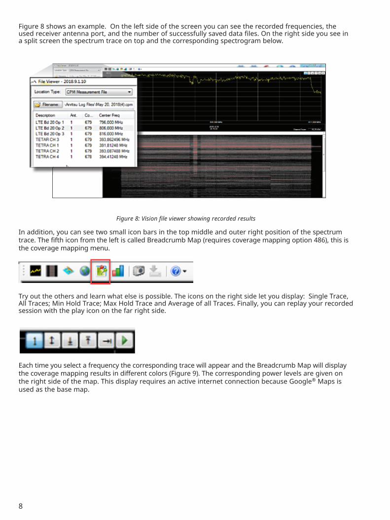
Figure 8 shows an example. On the left side of the screen you can see the recorded frequencies, the used receiver antenna port, and the number of successfully saved data files. On the right side you see in a split screen the spectrum trace on top and the corresponding spectrogram below.
Figure 8: Vision file viewer showing recorded results
In addition, you can see two small icon bars in the top middle and outer right position of the spectrum trace. The fifth icon from the left is called Breadcrumb Map (requires coverage mapping option 486), this is the coverage mapping menu.
Try out the others and learn what else is possible. The icons on the right side let you display: Single Trace, All Traces; Min Hold Trace; Max Hold Trace and Average of all Traces. Finally, you can replay your recorded session with the play icon on the far right side.
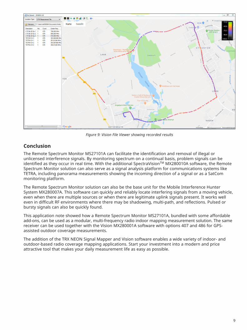
Each time you select a frequency the corresponding trace will appear and the Breadcrumb Map will display the coverage mapping results in different colors (Figure 9). The corresponding power levels are given on the right side of the map. This display requires an active internet connection because Google® Maps is used as the base map.
9
Figure 9: Vision File Viewer showing recorded results
Conclusion The Remote Spectrum Monitor MS27101A can facilitate the identification and removal of illegal or unlicensed interference signals. By monitoring spectrum on a continual basis, problem signals can be identified as they occur in real time. With the additional SpectraVisionTM MX280010A software, the Remote Spectrum Monitor solution can also serve as a signal analysis platform for communications systems like TETRA, including panorama measurements showing the incoming direction of a signal or as a SatCom monitoring platform.
The Remote Spectrum Monitor solution can also be the base unit for the Mobile Interference Hunter System MX280007A. This software can quickly and reliably locate interfering signals from a moving vehicle, even when there are multiple sources or when there are legitimate uplink signals present. It works well even in difficult RF environments where there may be shadowing, multi-path, and reflections. Pulsed or bursty signals can also be quickly found.
This application note showed how a Remote Spectrum Monitor MS27101A, bundled with some affordable add-ons, can be used as a modular, multi-frequency radio indoor mapping measurement solution. The same receiver can be used together with the Vision MX280001A software with options 407 and 486 for GPS-assisted outdoor coverage measurements.
The addition of the TRX NEON Signal Mapper and Vision software enables a wide variety of indoor- and outdoor-based radio coverage mapping applications. Start your investment into a modern and price attractive tool that makes your daily measurement life as easy as possible.
® Anritsu All trademarks are registered trademarks of their respective companies. Data subject to change without notice. For the most recent specifications visit: www.anritsu.com
• United States Anritsu Americas Sales Company450 Century Parkway, Suite 190, Allen, TX 75013 U.S.A. Phone: +1-800-Anritsu (1-800-267-4878)
• Brazil Anritsu Electrônica Ltda.Praça Amadeu Amaral, 27 - 1 Andar 01327-010 - Bela Vista - Sao Paulo - SP - Brazil Phone: +55-11-3283-2511 Fax: +55-11-3288-6940
• Mexico Anritsu Company, S.A. de C.V.Blvd Miguel de Cervantes Saavedra #169 Piso 1, Col. Granada Mexico, Ciudad de Mexico, 11520, MEXICO Phone: +52-55-4169-7104
• Russia Anritsu EMEA Ltd. Representation Office in RussiaTverskaya str. 16/2, bld. 1, 7th floor. Moscow, 125009, Russia Phone: +7-495-363-1694 Fax: +7-495-935-8962
• Spain Anritsu EMEA Ltd. Representation Office in SpainEdificio Cuzco IV, Po. de la Castellana, 141, Pta. 5 28046, Madrid, Spain Phone: +34-915-726-761 Fax: +34-915-726-621
• United Arab Emirates Anritsu EMEA Ltd. Dubai Liaison OfficeP O Box 500413 - Dubai Internet City Al Thuraya Building, Tower 1, Suite 701, 7th floor Dubai, United Arab Emirates Phone: +971-4-3670352 Fax: +971-4-3688460
• India Anritsu India Pvt Ltd.6th Floor, Indiqube ETA, No.38/4, Adjacent to EMC2, Doddanekundi, Outer Ring Road, Bengaluru – 560048, India Phone: +91-80-4058-1300 Fax: +91-80-4058-1301
• P. R. China (Shanghai) Anritsu (China) Co., Ltd.27th Floor, Tower A, New Caohejing International Business Center No. 391 Gui Ping Road Shanghai, Xu Hui Di District, Shanghai 200233, P.R. China Phone: +86-21-6237-0898 Fax: +86-21-6237-0899
• P. R. China (Hong Kong) Anritsu Company Ltd.Unit 1006-7, 10/F., Greenfield Tower, Concordia Plaza, No. 1 Science Museum Road, Tsim Sha Tsui East, Kowloon, Hong Kong, P. R. China Phone: +852-2301-4980 Fax: +852-2301-3545
• Japan Anritsu Corporation8-5, Tamura-cho, Atsugi-shi, Kanagawa, 243-0016 Japan Phone: +81-46-296-6509 Fax: +81-46-225-8352
• Korea Anritsu Corporation, Ltd.5FL, 235 Pangyoyeok-ro, Bundang-gu, Seongnam-si, Gyeonggi-do, 13494 Korea Phone: +82-31-696-7750 Fax: +82-31-696-7751
• Australia Anritsu Pty Ltd.Unit 20, 21-35 Ricketts Road, Mount Waverley, Victoria 3149, Australia Phone: +61-3-9558-8177 Fax: +61-3-9558-8255
• Taiwan Anritsu Company Inc.7F, No. 316, Sec. 1, Neihu Rd., Taipei 114, Taiwan Phone: +886-2-8751-1816 Fax: +886-2-8751-1817
Specifications are subject to change without notice.