68
SECTION THREE II 1111 Radio Navigation Equipmenp t ni -:O4 '

SECTION THREE
II
1111
Radio Navigation Equipmenp tni -:O4 '

Army Air ForcesWright Field
GRAPHIIIC
* Air Technical Service Command
Dayton, Ohio
SURVEYRadioUsed
and Radarby the Army
EquipmentAir Forces
Classification Ca nce;edOR Changed t c o i: / oe r (ALAuth: M
BY AUTHORITY OF DIRECTOR, ATSC 1 May 1945
This document contains information affectingthe national defense of the United States within the meaning ofthe Espionage Act (U.S.C. 50: 31, 32). The transmission ofthis document or the revelation of its contents in any mannerto any unauthorized person is prohibited.
DISTRIBUTION RECORD OFBY: Air Technical ServiceAtt: TSERR1B
THIS DOCUMENT IS MAINTAINEDCommand, Wright Field, Dayton;
CHobart R. CorpsColonel, Air Corps
of
1 -~"' -"-

SECTION 3- "RADIO NAVIGATION EQUIPMENT"
Description
AN/ARA-8 o . . a a a VHF Homing Adapter . a a . . . . . .AN/ARA-9 , . . . . . . Filter Equipment . . . . . . . .N/ARN-5 ". .a . . . .o Glide Path Receiver * * ...... .AN/ARN-6 a a a .. a a . Radio Compass a a a a . a a a a a aAN/ARN-7 a a a a a a a . . Radio Compass . a . a . . a . .. ..AN/A RN.-11 o .o . . . Radio Compass . . o . a . . . . . . . .AN/ARN-12 . a a . . a . a o Marker Beacon Receiver . .aa. . . .
A/ARR-1 a a a . . . . . . o . Compass Adapter .a : " . . a
AN/ARR-2 o a . .... . Radio Receiving Equipment . . . . . . . .Ah/ARR-6 . o . . . . . Automatic Alarm Receiver . . a o . .AI/CRM-3 . . . a • . ... . Radio Monitoring Set .. ... . . ..ANi/CRN-1 a a . . . . .. Buoy Transmitter . a . . .a a .. . * ..AI/CRN-2 . . .. . . Glide Path Transmitter . . . . .A /CRN- 4. . . . a o . o Paratroop Beacon . a e . . . .AN/CRN-10 . ... . .. Air-Transportable Localizer .... ..QT/CRT-3 . . . . . . .. Sea Rescue Transmitter . . . . . .
AN/MIRN-1 . . . . . Localizer Transmitter . . . . . . ./iR.-2 . . .. ., a . . . Radio Range Transmitter .. . . ..
AN/MRN-3 . . . .. .. Marker Beacon Transmitter . . . . . .BC-1206 . . . *. .Radio Receiver . . . . . . . e . a .
O-.43A . . . . . . . .
RC-103A . . .a . .IC-115A-. .. .. . a ..RC-193A. a . . .a . . .a aRC-198 . a a a a a .. .a a a
RC-210 . .. a . . . a . .SCR-269G * .. . . . a oSCR-277 o . a . .a . a .
80R-A 4,-r .. ... ..SCR-610 ,. . . .....
SCR-629 . . . . . . . . . . .
Marker Beacon Receiver . . .a .o oLocalizer Receiver . . . . . . . .oMarker Beacon Transmitter . . . . . . o .Marker Beacon . . . . . . a . . . . . .
Nomenclature
Filter Equipment . . . . .a . . . . UnclassifiedFilter Equipment . .a . . . . o . . o UnclassifiedRadio Compasso ..a a. a . . . . . UnclassifiedRadio Range Transmitter .. . .. ... UnclassifiedSea Rescue Transmitter . . . ... . . UnclassifiedFM Receiver-Transmitter ... . .. .UnclassifiedRadio Range Transmitter , . a. . : . .Restricted
• .... . -" - ..
Test Equipment
1-76 0 0 0 . . . . . . Test Set , . .... . . ... . UnclassifiedI-100 . o . . .. . oTest et .. . ....... . . . . . . Unclassified1-173 . * * * . . . o . . Test Set . . . . . . . . . UnclassifiedTS-l/ARR-1 . .. . . . . * , Test Set , . . .. .. . .. RestrictedTS-41/CRN-1 . . . o Test Set . .. . . . . . . . RestrictedTS-67/ARN-5 a. a a . . . Test Set . . . . . . . .. . RestrictedTS-170/ARN-5 . . . . .. . . Test Oscillator , . . . . . . . . . Unclassified
.............. ... , -
max
D i- !:
11~~~~~~~~~~ ' .11 ' ' . ' '* 1 .jw^ l ^ lt i
I~ i : a ai i ,:,,;i& 4 E:Bt~i,.B '~"i& w : B~;Ir. ~ ~ ,,/iJ
PresentSecurityClassification
UnclassifiedRestrictedUnclassifiedUnclassifiedUnclassifiedUnclassifiedUnclassifiedRestrictedRestrictedRestrictedUnclassifiedUnclassifiedUnclassifiedUnclassifiedUnclassifiedUnclassifiedUnclassifiedUnclassifiedUnclassifiedUnclassifiedUnclassifiedUnclassifiedUnclassifiedUnclassified
"s0,

Clearance Number AAF-MD-E89
orewardThis Graphic Survey of Radio and Radar Equipment used by the Army Air Forces
is intended to furnish authorized personnel with graphic and narrative data relativeto description, electrical and physical characteristics, purpose, and tactical em-
ployment of the radio and radar equipment used by the Army Air Forces.
Scoptw:
~ia1:t
Sauyesiq~dot
I#vdaaix;r ioes
y4Adho44
The Graphic Survey is not authorized as a basis for procurement storage, or issue,but is prepared only for information and guidance of research, development, pro-curement, storage, issue, and staff and planning activities.
This publication is intended to cover all active equipment, both in use and in de-
velopment. Publication is accomplished in a series of separate sections in orderthat reproduction and dissemination may be effected economically and expeditiously.
Permanentbinder covers are not furnished with the various sections of the GraphicSurvey, but the pages of each section are printed on 8 1/2 x 11 inch paper and punch-ed for the standard AAF three-hole binder, (binder, loose-leaf, 3 post, stock num-ber 8700-043800), commonly known within the AAF as "Technical Order Binder".With a few exceptions, data concerning each equipment is presented on two pages.The first page contains a description and information relative to use, installation,and electrical characteristics; the second page, photographs of the various com-
ponents and physical weights and dimensions. Within each section, the equipmentsare arranged alphabetically by official nomenclature and type designation.
Suggestions are invited for improvement of form, content, or to otherwise increasethe ultimate utility to the user within the scope and purpose of this publication. Com-ments should be addressed to the Commanding General, Air Technical Service Com-
mand, Wright Field, Ohio, Attention: TSERR1B, for consideration.
The Graphic Survey is classified ' because of the broad scope of the equip-ment covered in eachvolume and th et classification of many of the equipmentsEach addressee will be responsible for maintaining the security of his copies inaccordance with the provisions of AR 380-5. Security classification of each individ-ual equipment at the time of publication will be indicated on the pages relative tothat equipment.
Requests relative to distribution of this publication should be addressed to Com-manding General, Air Technical Service Command, Attention: TSERR1B. Revi-sions and additions are forwarded periodically to original addressees in order thatall copies may be kept up to date. Each copy has a serial number which is recordedon a master distribution file index.
Preparation, publication and distribution of the Graphic Survey is accomplished inaccordance with letter, Headquarters, AAF(AFDMA-2F), dated 5 April 1945, subject"Graphic Survey of Radio and Radar Equipment Used by the AAF". AAF reportclearance number AAF-MD-E89 has been assigned.
~3'576_-..-.r-- ""-
X-i~~at~~-

INDEXSectiot 3
1 MAY 1945Radio Aola/iois Cagpmed
NOMENCLATURE
AN/ARA-8AN/ARA-9
AN/ARN- 5AN/ARN-6AN/ARN-7AN/ARN-11AN/ARN-.12-
AN/ARR-1AN/ARR- 2AN/ARR- 6
DESCRIPTION
VHF Homing AdapterFilter Equipment
Glide Path ReceiverRadio CompassRadio CompassRadio CompassMarker Beacon Receiver
Compass AdapterRadio Receiving EquipmentAutomatic Alarm Receiver
TYPE STATUS*
Limited Procurement
StandardService TestStandard "Standard
StandardStandard
AN/CRM-3
AN/CRN-1AN/CRN-2AN/CRN-4.AN/CRN-10
AN/CRT-3
AN/MRN-1AN/MRN-2AN/MRN- 3
BC-1206
RC-43ARC-103ARC-115ARC-193ARC-198RC-210
SCR-269GSCR-277SCR-578SC R-610SCR-629
Radio Monitoring Set
Buoy TransmitterGlide Path TransmitterParatroop BeaconAir-transportable Localizer
Sea Rescue Transmitter
Localizer TransmitterRadio Range TransmitterMarker Beacon Transmitter
StandardStandardStandardStandard
Standard
Standard
Standard
Radio Receiver
Marker Beacon ReceiverLocalizer ReceiverMarker Beacon TransmitterMarker BeaconFilter EquipmentFilter Equipment
Radio CompassRadio Range TransmitterSea Rescue TransmitterFM Receiver-TransmitterRadio Range Transmitter
StandardStandard
Limited StanidardStandard
StandardStandardSub-Standard
X-126564
P
PDPPP

Radio Navigation1-76I'1001-173TS- 1/ARR-1TS-41/CRN-1TS-67/ARN-5STS-170/ARN-5
Test EquipTest Set StandardTest Set StandardTest Set StandardTest SetTest 'Set StandardTest. Set Limited StandardTest Oscillator Standard
*Status Defined:
D - (DEVELOPMENT): Initial pilot run has not yet been completed.
P - (PRODUCTION): Initial pilot run has been completed, and quantity productionis underway or has been completed.

AN/ARA-8~'Z7" Nfr~l
r[7,
Homing Adapter AN/ARA-8 is an adapter unitfor use with VHF receivers, such as those used in RadioSets SCR- 522 or AN/ARC-3, to provide the pilot with meansof homing on any transmitted carrier wave within the fre-quency range of 120 to 140 mc. This adapter gives a dot-dot-dash or dash-dot-dot signal when the aircraft is off thecourse to the left or right. While on course, a continuoustone is heard. When off course, the pilot turns right ifadot-dot-dash signal is heard and left if lie hears the dash-dot-dot signal.
Principal application of AN/ARA-8 is in fighteraircraft equipped with VHF command sets. This equip-ment can be used for air-to-air homing for purposes ofrendezvous and the gathering in of scattered combat planes.Homing can be accomplished on either CW, MCW or audiopulse signals.
Chief limitingfactor inthe operation of AN/ARA-8is that the distance range is limited to line of sight. Re-liable frequency range of this adapter is not the full rangeof VHF communication equipmentbut is limited to a rangeof approximately 20 mc. between 120 and 140 me. Whilethis 20 mc. range can be shifted up or down slightly in thefrequency band of the communication equipment, the cablelengths furnished with the adapter required frequenciesbetween 120 and 140 mc. for proper operation.
Army Supply Program requirements as of 31January 1945 were 3,500 for the calendar year of 1945.
AN/ARA-8 AntennaAirplane
POWER INPUTFREQUENCYTYPE OF SIGNAL
Installation, AFT Fuselage of P-51
z Izz36 WATTS120-140 MC.CW OR MCWPULSE
OR AUDIO
Homing Adapter AN/ARA-8 is used with VHF receivers to rjov actraft with means of homing on anytransmitted carrier wave within the frequency range of 120 to 140 in .
Nay 1945
.

AN/ARA-8
Modulator Keying UnitMD- 34/ARA- 8
Antenna RelayRE-12/ARA-8
EscutcheonMX-359/ARA-8
Antenna Assembly AS-148/ARA-8
ADAPTER
Component
Modulator Keying UnitMounting BracketAntenna AssemblyAntenna RelayMounting BracketEscutcheon
AN /ARA-8
Nomenclature
MD-34/ARA- 8MT-282/ARA-8AS-148/ARA-8RE-13/ARA-8MT-288/ARA- 8MX-369/ARA-8
TOTAL WEIGHT 12
Size
9" x 3' x 5"9"' x 4"27" x 3" x 2"1" x 2"' x 4"5" x 3"
Includes plugs, adapters, cord, switch, etc.* Less than one Pound.
Nay 1945
HOMING LBS.
Weight
5 Lbs.
5 Lbs.1 Lb.*
; SalFf3n

~~siii
Filter Equipment AN/ARA-9 is a radio rangefilter equipment consisting of a low impedance filter whichhas.a 1020-cycle band pass section and 1020-cycle bandreject section; and a switch for selecting either of the abovefilter sections or a filter-out position.
The primary purpose of this equipment is to per-mit the user (normally pilot or co-pilot) to isolate eitherthe voice or the range signal during periods of receptionof simultaneous transmissions of these signals. The equip-ment provides by means of a switch, facilities for voicereception only, range reception only, or normal use (nofilter in circuit). The switch, separate from the filter unit,is used to provide the selection of the desired facility.AN/ARA-9 is used in low impedance installations in whichthe output circuits of all of the radio equipments are con-nected for low impedance operation.
The switch is designed in such a way that it canbe used either mounted on the lid of the Filter F-21/ARA-9or mounted as a separate unit.
The filter is now being delivered as part of In-terphone Equipment AN/AIC-3.
Filter Equipment AN/ARA-9 is designed for usewith low impedance interphone and radio equipments in U. S.Army Aircraft.
There is' no special test equipment required for
AN/ARA-9
Interior view of Filter F-21/ARA-9the maintenanoe of the AN/ARA-9.
There were no Army Supply Program. require-ments as 1 February 1945.
POWER INPUT 4-6 V.TYPE OF SIGNAL.. AUDIOBAND PASS SECTION I1020 CYCLE
SE0CTION 1020 CYCLE
Filter F-21/ARA-9
Switchbox SA-58/ARA-9
'FILTER EQUIPMENT AN/ARA-9
Component Nomenclature
Filter F-21/ARA-9Switchbox SA=58/ARA-9
TOTAL WEIGHT
Size
2" x 3" x 4"3" x 2" x 2"
2 LBS.
Weight
2 Lbs.

Radio Receiving Equipment AN/ARN-5 is an air-borne radio receiving equipment used in conjunction withthe glide path transmitter of the AAF Instrument ApproachSystem to provide a visual indication of the glide path courseto be followed by the pilot of the aircraft during instrumentlanding operation.
Output of the receiver is fed into a cross-pointerindicator, and the position of the meter's horizontal pointerwith respect to the center of the face gives the pilot anindication of whether to fly up or down to remain on a pre-determined descent path to ground.
The receiving equipment operates on one of threefrequencies 332.6 mc, 333.8 mc, or 335 mc. In the eventof receiver failure, or the absence of a signal from theglide path system for any reason, a "fly up" indication isobtained.
Antenna System AS-27/ARN-5 is used with thedual installation of the glide path and localizer receivers.Antenna System AS-61-( )/ARN-5 is used when the glidepath receiver is installed without the localizer receiver.
Power input of the receiver is 1.35 amperes at28 volts d.c.. Reception of a 90 and 150 cycle modulatedsignal from the glide path transmitter over a range of 15miles is possible.
7-7PII
POWER INPUT 37 WATTS @ 28 VOLTSDC,
FREQUENCY 332.6 333.8 MC. 335 MTYPE OF SIGNAL CWRANGE 15 MILESSENSITIVITY AVERAGE 50 MICRO-
VOLTS
SELECTIVITY 6DB DOWN AT 400 KCOFF RESONANCE60 DB DOWN AT 2000KC OFF RESONANCE
TUBE COMPLEMENT
NO. TYPE NO. TYPE
7 6AK5 1 125R72 12SN7GT 1 28D7
Antenna System AS-27A/ARN-5
Radio Receiver R-89/ARN-5A
Antenna Assembly AS-61/ARN-5
RADIO RECEIVING EQUIPMENT AN/ARN-5
Component Nomenclature
Radio Receiveror Radio ReceiverMountingAntenna Assemblyor Antenna System
R-89/ARN-5R-57/ARN-5MT-28/ARN- 5AS-61/ARN-5AS-27/ARN-5
Size
6" x 12" x 7"6" x 12" x 7"6"x12" x3'Width 15 inches10" x 20" x 15"
and includes plugs, adapters, resistor, capacitor and rf cable.Nay 1945
TOTAL WEIGHT 2 0 LBS.
Weight
11 Lbs.11 Lbs.
3 Lbs.8 Lbs.2 Lbs.
SAN/ARN-5
Test equipment required for maintenance in-cludes TS-170/ARN-5 and TS-67/ARN-5.
Army Supply Program requirements as of 1 Feb-ruary 1945 were 33,718 equipments for the calendar year1945 and 19,630 for 1946.
~ ~ -"""~-
-~z

ucu CI 1S I tf
Radio Compass AN/ARN-6 is an automatic radiocompass which will provide either aural reception of mod-ulated radio signals in the frequency range of 100-1750kilocycles, aural-null directional indications of the arrivalof signals using a loop antenna, or automatic loop orien-tation and loop azimuth indication in degrees.
In addition to the four band frequency coveragefrom 100 to 1750 kilocycles, a 2800 to 5900 kilocycle highfrequency band has been added for emergency communi-cation use. The setwill notfunction as an automatic com-pass on this band.
Two loops are being developed: Loop AS-141/ARN-6 having the electrical characteristics of the LP-21and Loop AS-140/ARN-6 having the characteristics equalto a 12 inch air core loop. Bothloops contain an iron coretype of loop in order to decrease overall size. These loopshave the best possible anti-precipitation static character-istic and are of the blister type to reduce drag to a mini-mum. The smaller Loop AS-141/ARN-6 is to be used onfighters and the larger Loop AS-140/ARN-6 is to be usedon bomber and cargo planes.
The equipment operates from a 24 volt d.c. pow-er source.
Test equipment for maintenance will consist ofa test set incorporating I-100 and a special adaptor.
Army Supply Program requirements as of 8 Feb-ruary 1945 were 2,000 equipments for the calendar year1945.
TUBE COMPLEMENT
NO. TYPE NO. TYPE
5 12SK7 4 12SX7GT1 12SY7 2 6A7GT1 12SW7 2 2050
Indicator ID-XA-6/ARN-6
Indicator ID-XA-7/ARN-6
Indicators of AN/ARN-6 record simultaneously transmiss-ion bearing in respect to flight course.
POWER INPUT 130 WATTS @ 26.5VOLTS D.C.
POWER OUTPUT 700 MILLIWATTS PEAKFREQUENCY 100-1750 KC AND
2800-5900 KC.
TYPE OF SIGNAL CW; MCW/VOICESENSITIVITY 5 MICROVOLTS/METERSE LECTIVITYANTENNA LOOP FIXED OR RO-
TATABLE, WITHREMOTE INDICATIONOF LOOP POSITION.
(DUAL-REMOTE CON-TROL AND ONE SET OFLOCAL CONTROLS.)
PILOTS & NAVIGATORS INDICATORS ARESYNCHRONIZED WITH LOOP POSITION -MOVEMENT & FIXES BY LOOP ARERECORDED SIMULTANEOUSLY BY EACHINDICATOR - THUS THE INDOCATOR W/LLFOINT TO (& RECORD BY DEGREES) THESOURCE OF ANY SELECTED TRANSMISSION
Radio Conrr pass AN/ARN-6,intended for installation in all types. of aircraft, provides visual indication of thedirection .rom any equipped aircrafttoany broadcast band transmitter operating on the 100-1750 kc band.
AN/ARN-6

AN/ARN-6
Radio Control BoxesC-149/ARN-6(XA-3)
Radio Compass UnitR-101/ARN-6(XA-3)
Indicator ID-92/ARN-6(XA-3)
Indicator ID-91/ARN-6(XA-3)Loop AS-141/ARN-6(XA-3)
RADIO COMPASS AN/ARN-6 TOTAL WEIGHT
Component
Radio Compass UnitMountingIndicatorIndicatorCoupling UnitControl BoxLoop
Nomenclature
R-101/ARN-6MT-274/ARN-6ID-91/ARN-6ID-92/ARN-6CU-65/ARN-6C-149/ARN-6AS-.141/ARN-6
Size
16" x 12' x 8"16" x 12" x 3"
5"x8' x4"7" x 6" x 17"
* less than one poundand includes cables, cords, connectors, etc.
55 LBS.
Weight
32 Lbs.7 Lbs.
3 Lbs.10 Lbs.
,.te . - (.

-~~ * i,;i
Radio Compass AN/ARN-7 is an automatic bear-ing-indicating radio compass operating from a 400-cycle,115-volt power supply. It provides aural reception of mod-ulated radio signals as an ordinary 100 to 1750 kc. radioreceiver and automatic loop orientation and loop azimuthindication in degrees. Itis similar to Radio Compass SCR-269-G and employs all its components with the exceptionof Radio Compass Unit BC-433-G and Radio Control BoxBC-434-A.
Frequency range of the AN/ARN-7 is dividedinto four bands covering 100 to 1750 kc. It is manuallytuned fran either of two remote positions, with bands switch-ed electrically from the position having control. When in -stallations are made which use only one remote control,no switching of control is necessary andthe one radio con-trol box used has control at all times.
The new receiver, Radio Compass R-5/ARN-7,is a 15-tube superheterodyne capable of C.W., tone andvoice reception. The addition of the 100-200 kc. band makespossible long range operation in connection with establishedlow frequency transmitters in many parts of the world.
AN/ARN-7 was designed originally as an interimcompass, capable of low frequency reception, pending com-pletion of the development of Radio Compass AN/ARN-6.
Test equipment for AN/ARN-7 includes Test SetI-100-A.
Army Supply Program requirements as of 19October 1944 were 25,394 for the calendar year 1945.
TUBE COMPLEMENTNO. TYPE NO. TYPE4 6K7 1 6L72 6F6 1 6J52 6B8 1 6N72 2051 1 6SC71 5Z4
Loop and Loop Housing for AN/ARN-7 installed in fuselageabove pilot and co-pilot on C-64 aircraft.
POWER INPUT 115 VOLTS, 400 CYCLESFREQUENCY 100 KC TO 1750 KCTYPE OF SIGNAL CW, TONE, VOICERANGE 100 MILESSENSITIVITY 40 MV/METERSELECTIVITY 10 TIMES RESONANT
INPUT FOR 6.3 KC.ANTENNA LOOP
16/B/KC. 7 Ia C
KNOWING THE TRANSMIT TING FiGIVEN GROUND STATION AND ITPOSITION OF THE AIRCRAFT MA
In additior to its high frequency band of 2800 to 5900 kc., Radio Compass AN/ARN-7 provides facilities forhoming a .d plotting of aircraft positions similar to those of other Automatic Radio Compasses.
Nay 1945
AN/ARN-7

I~Ch BS~I4I E
Radio Control Boxes C-4/ARN-7
Radio Compass UnitR- 5/ARN-7
Indicator I-82-A Indicator I-81-ADehydrator Dehydrator Hose
RADIO COMPASS
Component
Radio Compass UnitRadio Control BoxLoopIndicator (Navigator's)Indicator (Pilot's)IndicatorRelay
Relay BK-22-E
AN /ARN-7
Nomenclature
R- 5/ARN-7C-4/ARN-7(2 each)LP-21-AMI-82-AI-81-AID-65/ARNBK-22-K
TOTAL WEIGHT 98
Size
8" x 12" x 20"8" x 8" x 4"26" x 15" x 9"4" x 4" x 4"5" x 5" x 4"
12" x 7" x 3"
and includes plugs, adapters, cords, insulators, operatingchart, shaft and casing, tag, wire and set of fittings.
Nay 1945
AN/ARN-7
LBS.
Weight
47 Lbs.4 Lbs.
10 Lbs.1 Lb.1 Lb.
7 Lbs.

4 Stu
Radio Compass AN/ARN-11 is an aircraft navi-gational equipment which indicates the direction of a se-lected transmitting station and also functions as a generalradio receiver.
Loop reception on two of the three bands, thatis, on the 200-400 kc. and 550-1200 kc. bands, providesleft-right compass coverage, while a non-directional an-tenna offers reception on the 2900-6000 kc. band.
Visible indication by means of a left-right in-dicator gives the general direction from which the receivedsignal is transmitted, and visible indication of relativebearing between the aircraft and the transmitting stationby means of an azimuth dial.
Generally, a 9-inch rotatable loop, such as theMN-20, is used with this equipment, but on slower aircraft,such as cargo aircraft, an 18-inch loop is often used. The18 inch MN-24 is a preferred loop for use with this equip-ment when installed onlow-speed airplanes because of itsexcellent anti-precipitation-static qualities.
Any of the MN-28 series remote control boxesmay be used to provide band switching.
Army Supply Program requirements as of 1 Feb-ruary 1945 were 2,921 forthe calendar year 1945 and 2,390for 1946.
POWER INPUT 84-126 WFREQUENCY COMPASS RECEPTION
200-400. 550-1200 KCCOMMUNICATION RE-CEPTION 20Q-400,500-1200, 2900-6000 KC
TYPE OF SIGNAL VOICE, MCWRANGE 100-150 MILES
TUBE COMPLEMENTNO. TYPE NO. TYPE
5 6K7 2 6J52 6N7 1 6F61 6L7 1 6B8
Indicator IN-4D
Remote ControlUnit MN-28LB
Loop Transmission Cable
Meter FieldLoad Assembly
Loop MN-24C
RADIO COMPASS
Component
Radio Compass UnitRemote Control UnitAzimuth Control UnitLeft-Right IndicatorMeter Field Load AssembRotatable LoopLoopLoop Transmission CableControl UnitControl PanelControl Panel
Radio Compass Receiver MN-26LB
AN/ARN-11
Nomenclature
MN-26LBMN-28LBMN-40DIN-4D
ly Bendix No. AA18824-1MN-24CAS-138/ARN
Bendix No. AC55966-1MC-204-AC-135/ARC-136/AR
TOTAL WEIGHT 60 LBS.
Size
8" x 12'' x 18"4" x 5" x 8"
3" x 3" x 3"
18" diam.14" x 11" x 10"42" and 168" long
17" x 8" x 5"5" x 3" x 2"
and includes plugs, set of fittings, shaft and casing and tag.* Less than one pound.
May 1945
AN/ARN -11
Weight
37 Lbs.3 Lbs.
2 Lbs.
5 Lbs.4 Lbs.

Marker Beacon Receiving Set AN/ARN-12 is alightweight airborne marker beacon receiver utilizing asuperheterodyne type circuit with a crystal controlled os-cillator. It is designed to give aural and visual indicationswhen flying over any army marker beacon transmitter ataltitudes between 10 and 4,000 feet, and over CAA markerbeacon transmitters at altitudes between 100 and 35,000feet. Reception is on the standard marker beacon channelof 75 me. The equipment responds to a 75 mc. signal whichis modulatedby400, 1,300 and 3,000 cycles. The receivingset is designed for operation from the aircraft 24 volt de.system.
A filter is required for selection of indicationof 400, 1,300 and 3,000 cycle modulation. This is providedin a separate unit which may be installed or omitted de-pending upon the mission of the aircraft.
This equipment will replace Marker Beacon Re-ceivers RC-193, RC-39, and RC-43.
Test Equipment required for maintenance in-cludes Test Set 1-76.
Army Supply Program requirements as of 1 Feb-ruary 1945 were 11,860 sets forthe calendar year 1945,and 23,599 sets for 1946.
TUBE COMPLEMENT
NO. TYPE NO. TYPE
2 28D7 2 6AL55 6AJ5
IF tLASSIFI[P
Antenna Assembly AS-215(XA)/ARN installed bottom mid-fuselage AT-11 airplane. 1-Interior 2-Exterior
POWER INPUT 72 WATTS @ 24 VOLTSDC.
FREQUENCY 75 MCTYPE OF SIGNAL MCWRANGE ARMY BEACONS 10 TO
400 FEET CAA BEA-CONS 100 TO 35.000 FT
SENSITIVITY 500 - 1500 MICROVOLTSELECTIVITY 600 at 700 KC
Radio Receiver R-122/ARN-12
Antenna Assembly
MARKER BEACON RECEIVING SET AN/ARN-12 TOTAL WEIGHT 25 LBS.
Component
Radio ReceiverApplique UnitMountingAntenna Assembly
Nomenclature
R-122/ARN-12
MT-28/ARNAS-215/ARN
Size
6" x 10" x 6"
10" x 2" x 6"Length 19" x Diam. 12"
and includes cords, plugs, cables, etc.
May 1945
AN/ARN-12
Weight
9 Lbs.7 Lbs.1 Lb.5 Lbs.

2j4g-jjjW
Radio Receiving Equipment AN/ARR-1 (Navy ZBAdapter) is an airborne compass adapter used for receptionof signals covering the range 234 to 258 mc, amplitude mod-ulated by a keyed rf signal in the 540 to 830 kc. range.
When the pilot is provided with a decode card,he is able to use this equipment to interpret the directionalsignals transmitted by the Navy Model YG Homing Beacon,or other homing beacons operating a rotating, directionalantenna and transmitting within the frequency range of thereceiver. In addition to the 12 30-degree direction sectorswhich are separately identified by code letter, a true northposition relative to the transmitter is indicated by the codeletter to assist the pilot in compass orientation.
Effective range of this equipment is 40 to 70miles at 10,000 feet, with greater range possible at higheraltitudes.
Test equipment required for maintenance in-cludes Test Set TS-1/ARR-1 and Test Oscillator TS-24/ARR-2.
There were no Army Supply Program require-ments as of 1 February 1945.
POWER INPUT 6 WATTS ( 28 VOLTS3 WATTS 250 VOLTS
FREQUENCY 234-258 MCTYPE OF SIGNAL CW: MCWe VOICESENSITIVITY 40 MICROVOLTSSELECTIVITY 20 DB. DOWN AT 1.5%
OFF RESONANCERANGE 40-70 MILES AT 10.000
FEET
AN/ARR- 1
Installation photograph indicates (1) Relay RE-1/ARR-1,and (2) Radio Receiver R-1/ARR-l
TUBE COMPLEMENT
NO. TYPE NO. TYPE
4 954
Used with a suitable reoeiver, Radio Receiving Equipment AN/ARR-1 permits aircraft to home on a ZBkeyed transmitter which sends out coded signals to each 300 of 3600
May 1945

AN/ARR-1-~ S o i : j
Radio Receiver R-1/ARR-1
Antenna AT-5/ARR-1
Relay RE-1/ARR-1
RADIO RECEIVING EQUIPMENT AN/ARR -1 TOTAL WEIGHT 11 LBS.
Component
Radio ReceiverMountingRelayAntennaAdapterMounting Plate
Nomenclature
R-1/ARR-1MT-2/ARR-1RE- 1/ARR-1AT-5/ARR- 1M-359MT-3/ARR-1
Size
4" x 4" x 13"12" x 4" x 1/8"3" x 4" x 5"12" long1" x 1" x 1"5" x 4" 1"
*Less than one pound.and includes slip cover, plugs, and radio frequency cable.
May 1945
Weight
4 Lbs.*
2 Lbs.1 Lb.*

Radio Receiving Equipment AN/ARR-2 is a self-contained high frequency radio receiving and homing equip-ment capable of providing the pilot with directional orient -ation within 15 degrees when used with the YG Beacon Trans-mitter which operates at a carrier frequency of 234 to 258mc modulated at a frequency of 540 to 830 kc.
The receiver, may be mounted on its own rackor installed in the racks of the SCR-274-N. It employs twoseparate circuits, one to amplify and detect the UHF signalthe other to produce an output at the modulated frequency.Output from the high frequency circuit is fed to a super-heterodyne receiver incorporated within the receiver. Abeat-frequency oscillator is used in the i-f circuit of thesuperheterodyne portion of the receiver to-provide a CWbeat note for aural reception of the keyed modulation fre-quency of the transmitter.
The UHF carrier frequency is turned by meansof a calibrated dial located on the front panel. Coverage ofthe 540 to 830 kc modulation frequencies is accomplishedby using six channels, each capable of being tuned and pre-set anywhere within the modulation frequency range.
A switching arrangement allows any one of thesesix preset channels to be selected by means of a rotatingswitch inthe control box, and a beat note is provided in theremote control box for adjustment of the audio pitch. A vol-ume control for adjustment of the output to the desired levelis also provided. ..,,. ...... ,.
u
Mounting Base MT-5/ARR-2
Radio ReceiverR-4/ARR-2
Control Box C-2/ARR-2Dynamotor DY-2/ARR-2
Antenna AT-5/ARR-1
RADIO RECEIVING EQUIPMENT AN/ARR-2
Mounting RackMT- 7/ARR- 2
TOTAL WEIGHT 19 LBS.
Component
Radio ReceiverMounting RackControl UnitMounting PlateMounting BaseDynamotor UnitAdapterRight Angle CouplingAntenna
Nomenclature
R-4/ARR-2MT-7/ARR-2C-2/ARR-2MT-4/ARR-2MT- 5/ARR- 2DY-2/ARR- 2MX-2/ARR-2MX-22/ARR-2AT-5/ARR-1
Size
12" x 5" x 6"14" x 6" x 5"'4" x 6" x 3"6" x 4"11" x 7" x 2"5" x 3" x 3"1-1/4" dia.1-1/4" dia,length 12"
and includes plugs, tuning shaft and radio frequency cable.
*Less than one pound.May g945
Weight
7 Lbs.2 Lbs.1 Lb.*
1 Lb.3 Lbs.1 Lb.1 Lb.1 Lb.
S AN/ARR- 2
Test Oscillator TS-24/ARR-2 is used to check op -eration of this equipment.
There were no Army Supply Program require-ments of 1 February 1945.
POWER INPUT 45 WATTS (28 VOLTSD-C
FREQUENCY 234-258 MC CARRIERSIGNAL 540-830 KC(6 CHANNEL) MOD-ULATED BY CW:MCWVOICE
TYPE OF SIGNAL CW, MCW, VOICERANGE 40-70 MILES AT
10 000'SENSITIVITY 10 MICROVOLTSACCURACY PLUS OR MINUS 15
DEGREES
TUBE COMPLEMENTNO. TYPE NO. TYPE3 6AK5 7 90011 12A6

UCLASSIHlEDAN/ARR-6
Radio Receiving Set AN/ARR-6 is an airborneautomatic receiver designed to receive a fixed 500 kc,signal. It provides for automatic reception of signals ininternational distress frequency, and upon receipt of a sig-nal a light is automatically flashed on at the receiver andon a jack box at some remote point.
The radio receiver is tuned to the internationaldistress frequency. Sufficient band width is provided tocompensate for small frequency variation between trans-mitters used and to guarantee reception of signals withinthe greater portion of the guard band on either side of theinternational distress band.
The receiver is so designed that the indicatingdevice is not activated under the influence of atmosphericdischarges. Sensitivity is such as to assure the receptionof a distress signal from Radio Set SCR-578 at a distanceof at least 150 miles over water. Power is supplied dir-ectly from the 28-volt source in the aircraft. The equip-ment operates at altitudes up to 50,000 feet and utilizesthe fixed antenna on the aircraft.
No specialtest equipment is requiredfor main-tenance.
There were no Army Supply Program require-ments as of 30 November 1944.
POWER INPUT 28 VOLTS D.C.POWER OUTPUT 10 MILLIWATTSFREQUENCY 500 KC. FIXED TUNEDTYPE OF SIGNAL SUSTAINED MCWRANGE 150 MILES OVER WATERSENSITIVITY S MICROVOLTSSIGNAL ACCEPT. 20 WORDS PER MINUTEKEYING RATE
TIME DELAY 50 TO 15 SECONDS
TUBE COMPLEMENT
NO. TYPE NO. TYPE
2 6AK5 1 6H61 12C8 3 65G71 28D7 1 25L6
Relieving radio operators from manually monitoring the international distress frequency, Radio Set AN/ARR-6 provides an automatic alarm in the equipped aircraft, bringing to the attention of the pilot and/or radiooperator that a distress signal is being transmitted in the vicinity.May 1945

ASAN/ARR IIAN/ARR- 6 IIJ
Jack BoxJ-XA-10O/ARR-6(XA-1)
RADIO RECEIVING
Component
Radio ReceiverJack Box
SET AN/ARR-6
Nomenclature
TOTAL WEIGHT
Size
7" x 6" x 8"2" x 3" x 4"
and includes cables, adapters, plugs, etc.
5 LBS.
Weight
4 Lbs.1 Lb.
May 1945

li*d _ ' L a n 4 I l F
Radio Monitoring Set AN/CRM-3 is a radio re-ceiving equipment mounted in a plywood cabinet providedwith an external antenna mounted on the top of a 15-footmast. Power to operate the receiver is supplied from avoltage regulated power supply mounted in the same ply-wood cabinet. This equipment is used with TransmittingEquipments AN/MRN-1, AN/CRN-3 and AN/CRN-10.
AN/CRM-3 provides means of locating the coursewith respect to the runway, checks the course width andtransmitter radiation pattern and can also be used at anypoint within two miles of the transmitter to give an on-offindication of signal. A greenpilot lamp indicates the local-izer signal is being received by the radio monitoring set,and a red pilot lamp and a continuous buzz indicates theabsence of a localizer signal.
No test equipment is required.There were no Army Supply Program require-
ments as of 1 February 1945.
POWER INPUT 115/230 VOLTS AC:12 VOLTS DC
FREQUENCY 50-65 CYCLES PERSECOND
RANGE 2 MILES WHEN USEDAS MONITOR1000 FT. WHEN
TUBE COMPLEMENT
NO. TYPE NO. TYPE1 12A6 3 717A1 12AK7GT 1 5U4 G2 12SG7 1 6SJ 72 12SQ7 1 VR-1052 12SR7 2 6Y6
Alarm Assembly ID-85/CRM-3
IRadio Monitoring SetAN/CRM-3
RADIO MONITORING SET AN/CRM -3
Component Nomenclature
Antenna AssemblyIndicator Power Supply ConsoleAlarm AssemblyRadio Control BoxRadio ReceiverIndicatorDynamotor
AS- 111/CRM-3CY-151/CRM-3ID-85/CRM-3BC-732-ABC-733-DI-101-C or DDM-53-AZ
Indicator Power Supply ConsoleCY-151/CRM-3
TOTAL WEIGHT 150 LBS.
Size
15 foot mast15" x-20" x 13"8" x 4" x 6"3" x 3" x 4"7" x 5" x 13"3" x 3" x 4"
" x 3" x 5"
Weight
10 Lbs.70 Lbs.
5 Lbs.1 Lb.
21 Lbs.2 Lbs.3 Lbs.
Includes mooring anchor, mountings, cords and adapter.Nay 1945
AN/CRM-3
0:

U Nt sstil I[AN/ CRN-1
Radio Transmitting Equipment AN/CRN-1 is asingle-tube, battery-powered, low frequency buoy trans-mitter, normally launched into the water from the bottomhatch of bombardment-type aircraft to mark the locationof a life raft or other object. It is housed in a cylindricalcase and consists of a radio transmitter, set of tubes, bat-teries, and a ballistic telescopic antenna. A base-ball typeparachute is used to lower the equipment safely from theaircraft to the water.
This equipment covers the frequency range of1400 to 1750 kilocycles and provides for automatic trans-mission of a predetermined signal on which airc raft equip-ped with standard radio compasses may home. Thetransmitted signal consists of a CW signal keyed 180 timesper minute and interrupted every 30 seconds by a singlecode letter. Signals may normally be picked up over atleast 50 miles of open sea.
The equipment is battery-operated and has a use-fullife of 12 hours. A timer is provided so the transmitterwill automaticallyturn on at any predeterminedtime up to12 hours after which the transmitter will still operate for12 hours. The buoy has a soluble plug which will cause itto sink after 50 to 60 hours in the water.
This equipment is used to provide a referencepoint for search patterns in sea rescue work and in anti-submarine activity. No special training or instructionsare necessary for its use.
Test equipment required for maintenance in-cludes Test Equipment TS-41/CRN-l.
Army Supply Program requirements as of 30November 1944 were 1,050 equipments for the calendaryear 1944 and 1,500 equipments for 1945.
In releasing this bouy the crew member must he securelylashed.
POWER INPUTPOWER OUTPUTFREQUENCY
BATTERY PACK8 WATTS1400-1750 KC
TYPE OF SIGNAL OWRANGE 50 MILES
TUBE COMPLEMENT
NO. TYPE NO. TYPE
1 6V6GT/G
Radio Transmitting EquipmentAN/CRN-1
RADIO TRANSMITTING EQUIPMENT AN / CRN-1
Component Nomenclature
Radio TransmitterParachuteBatteryMay 1945
T-2/CRN-lMX-91/CRN-lBA-201/CRN
TOTAL WEIGHT 52 LBS.
Size
49" high x 8" diam.12" high x 7" diam.14" long x 6" diam.
Weight
34 Lbs.4 Lbs.
14 Lbs.
---

~ ~Sl~fE%1all ~~Rs A
Radio Set AN/CRN-2, an air transportable glide-path transmitter, is a component of the AAF InstrumentApproach System. Signals from the transmitter are re-ceived by the pilot of the aircraft to be landed over Re-ceiving Equipment AN/ARN-5, providing visual indicationof the proper course of descent inthe verticalplane duringinstrument landing operation. At an altitude of 3,000 feetit provides a straight-line glide path course with good def-initionfrom a minimum distance of 15 miles from the pointof landing contact with the ground. The angle indicatedbetween the horizontal and the glide path is readily adjust-able between 2 and 5 degrees.
The equipment operates in the frequency rangeof 329 to 335 me. At present, crystals are supplied to op-erate at 332.6, 333.8 and 335 me.
Transmitting components are installed in an airtransportable trailer which is a part of the equipment. Theantenna system consists of a 30-foot mast which supportsthe folded dipole antennas. A monitor is included in theequipment .to provide automatic cut-off of the glide pathcarrier in the event of change in path positions, modu-lation frequency, field strength and/or failure of the moni-tor. Two-way communicationbetweenthe set and the con-trol center of the instrumentapproach system is providedby Radio Set SCR-610.
Test equipment required for maintenance isfurnished with the basic equipment. Power for operationis obtained from a 115 volt, 60-cycle Hower source.
Army Supply Program requirements as of 27December 1944 were for 450 equipments for the calendaryear 1944 and 145 equipments for 1945.
POWER INPUT 115 WATTS@115 VOLTSPOWER OUTPUT 25 WATTS OF CW
POWERFREQUENCY 329-335 MC. CRYSTAL
FREQUENCIES 332.6MC. 333.8 MC. 335 MC.
TYPE OF SIGNAL STRAIGHT LINE GLIDEPATH-DOUBLE BEAMMCW SYSTEM
RANGE 15 MILES AT 3000 FEET
TUBE COMPLEMENT
NO. TYPE NO. TYPE
2 6SJ7 3 5U4G1 832 2 8361 829B 1 9574 8025 1 lLH41 9002 1 lLC61 6SK7 5 1LN53 6SN7GT 2 3B7/12911 6J5 1 1B4/12942 OB3/VR-90 4 3D6/12991 OD3/VR-150 1 1005
Close up of Radio Set AN/CRN-2 showing 1.Transmitter 2.Power Supply 3.Power Unit
May 2945
AN/ CRN-2

AN/ CRN-2L ~ -
In operation Radio Set AN/CRN-2 is located approximately 750 feet from the approach end of the runway and400 feet to one side (or the other) of the runway's center line.
May 1945

mm- AN/CRN
LObER ANTB7NAYCANSM/T 9O
SCYULE (LPPEXI )I
APPROXIMA EL Y _______
: O FE T...
BE. .
: / GLIDE COURSE OF2 '('AOJU9S74AB.. 2O I'IS FORMEO BY INT ERSECTON OF LOWERPORTION OF 90 CYCLE LOBE AND UPPFR
OBE
aC/A A
a
CROSS SECTION A OFGLIDE PATH LOBES
(/0 MILES FROM TRANSMITTER)
Radio Set AN/CRN-2 is a self contained glide path transmitter, part of the AAF instrument approach system.The glide path beam is obtained by two lobes which intersect and project outward from the runway at an angleof 2° for a distance of approximately 15 miles.
May 1945
poll( IA
"^*1

AN/ CRN-2
Radio Set AN/CRN-2 packs into a simple trailer which permits rapid transport by air or ground.
RADIO SET AN / CRN-2 TOTAL WEIGHT 1800 LBS.
Component
Radio TransmitterRectifier Power UnitAuto TransformerAntenna SystemTrailerPower UnitChestKerosene Obstruction LightBatteryVoltmeterRadio Receiver-TransmitterPower UnitVibratorAntennaHandsetVibrator
Nomenclature
T-3/CRN-2PP-29/ARN- 2MX-95/CRN-2AS-2/CRN-2C-1/CRN-2PU-1/CRN-2CY-63/CRN-2
BA-57 (2 each)TS-40/CRN-2BC-659-()PE-120-()VB-12 (2 each)AN- ,9-CTS--: 3-( )VTE-.3 (2 each)
Size
39" x 25" x 24"24" x 21" x 25"8" x 8" x 12"
5' x 10' x 5'20" x 32" x 16"16" x 16" x 17"15" x 6" diam.16" x 7" x '10"12" x 5" x 4"7" x 14" x 15"7" x 14" x 15"2" x 3" x 2"154" long extended10" x 3" : 3"2" x 3' x 23
and includes mountirngs tooi cables, c:>st L:, and other accessories.
Weight
227 _Lbs.254 Lbs.48 L.bs.
1033226
777
62232525
1
Lbs.Lbs.Lbs.Lbs.Lbs.Lbs.Lbs.Lbs.Lb.
b..L.i
ySP AS~sEl~i~
fir, t A4iiii-i, U
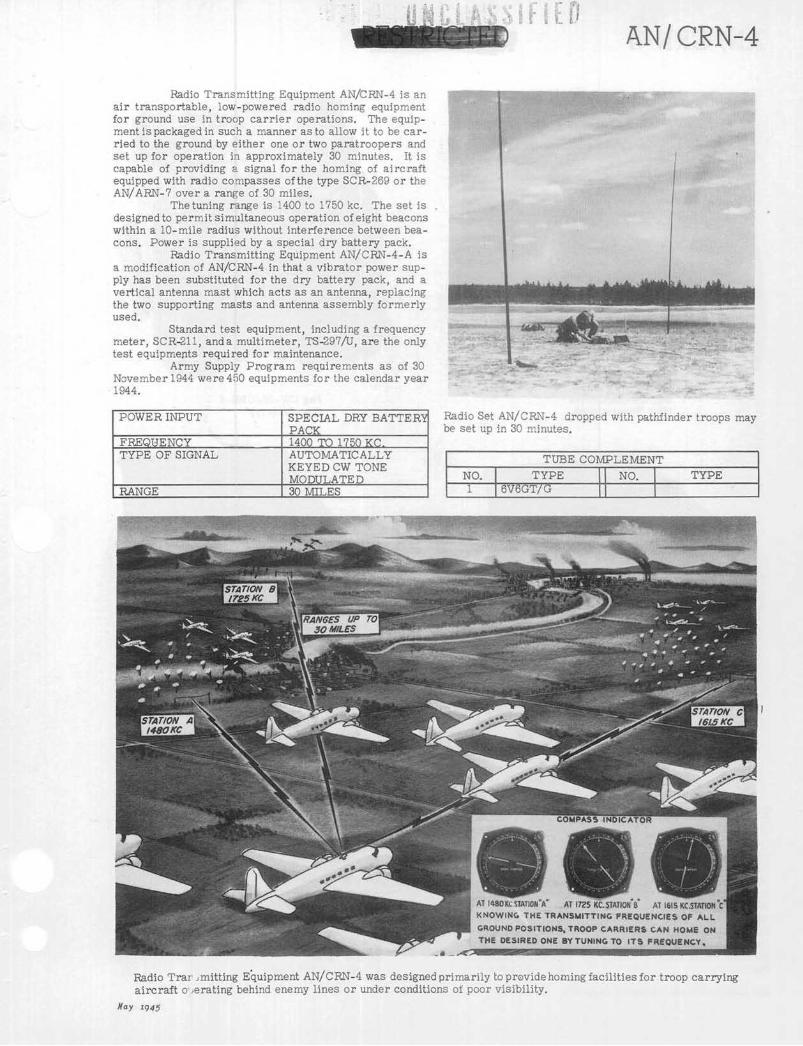
Radio Transmitting Equipment AN/CRN-4 is anair transportable, low-powered radio homing equipmentfor ground use in troop carrier operations. The equip-ment is packaged in such a manner as to allow it to be car-ried to the ground by either one or two paratroopers andset up for operation in approximately 30 minutes. It iscapable of providing a signal for the homing of aircraftequipped with radio compasses of the type SCR-269 or theAN/ARN-7 over a range of 30 miles.
The tuning range is 1400 to 1750 kc. The set isdesigned to permit simultaneous operation of eight beaconswithin a 10-mile radius without interference between bea-cons. Power is supplied by a special dry battery pack.
Radio Transmitting Equipment AN/CRN-4-A isa modification of AN/CRN-4 in that a vibrator power sup-ply has been substituted for the dry battery pack, and avertical antenna mast which acts as an antenna, replacingthe two supporting masts and antenna assembly formerlyused.
Standard test equipment, including a frequencymeter, SCR-211, anda multimeter, TS-297/U, are the onlytest equipments required for maintenance.
Army Supply Program requirements as of 30November 1944 were 450 equipments for the calendar year1944.
POWER INPUT SPECIAL DRY BATTERPACK
FREQUENCY 1400 TO 1750 KTYPE OF SIGNAL AUTOMATICALLY
KEYED CW TONEMODULATED
RANGE 30 MILES
Radio Set AN/CRN-4 dropped with pathfinder troops maybe set up in 30 minutes.
TUBE COMPLEMENT
NO. TYPE NO. TYPE1 6V6GT/ G
Radio Trar mitting Equipment AN/CRN-4 was designed primarily to previde homing facilities for troop carryingaircraft o-ierating behind enemy lines or under conditions of poor visibility.
May 9ig45
AN/ CRN-4

~~Ct~~~[LUAN/ CRN-4
Bag CW-25/CRN-4(For Transmitter)
Bag CW-26/CRN-4(For Battery)
Battery BoxCY-83/CRN-4
RADIO TRANSMITTING EQUIPMENT AN/CRN-4
Component- Nomenclature
Radio TransmitterAntenna AssemblyBattery BoxBagBagAntenna AssemblyVibrator Power UnitBag
T-59/CRN-4AS-85/CRN-4CY-83/CRN-4CW-25/CRN-4CW-26/CRN-4AS-243/CRN-4APP-161-()-CRN-4ACW-125/CRN-4A
TOTAL WEIGHT 55 LBS.
Size
7" x 6" x 13"33" x 12" x 5"13" x 6" x 7"9" x,8" x 14"9" x 8" x 14"13" x 6" x 7"6" x 5" x 13"4" diam. x 36" long
and includes operating spare parts kit.
Weight
10 Lbs.16 Lbs.17 Lbs.
4 Lbs4 Lbs.5 Lbs.5 Lbs.1 Lb.
Nay 1945

QNCLASIFIrfl
Radio Set AN/CRN-10 is an air transportabletrailer mounted localizer equipment used in the AAF In-strument Approach System. Function of this equipment isto provide a signal to guide an RC-103 equipped aircraftto the line of a runway. This equipment is lighter in weightbut functionally similar to Radio Set AN/MRN-l. It is in-tended for use where air transportable localizer equipmentis desirable and is expected ultimately to replace RadioSet AN/MRN-1.
Mounted on a trailer similar to that utilized forRadio Set AN/CRN-2 (glide path transmitter), the equip-ment is suitable for transportation in cargo type aircraft.Care must be taken when installing the equipment and itsradiation system to insure a minimum hazard to aircraft.The power unit is mounted on wheels rather than in thetrailer and is also air transportable.
Provision is made for remote start-stop controland also for two-way communications between the monitorlocation, the localizer equipment, and the control centerof the instrument landing system.
The equipment is operable froma 115-230 volt, 50-60cycle power source and inclodes a standard auxiliary gaso-line engine power unit which is capable of continuous oper-ation. A course monitor provides visual and aural alarmin the event of change in course positions, modulation fre-quencies, field strength, or failure of the monitor. Accur-acy of the course definition and the straightness or stabi-lity of the defined course permits the landing of militaryaircraft on a runway 100 feet wide at a minimum distanceof 6,000 feet from the localizer equipment. This equip-ment represents considerable improvement over Radio SetAN/MBN-1 In its reduced size and weight and improvedantenna pattern.
Test equipment required for maintenance is in-cluded in parts for the set.
Army Supply Program requirements as of 1 Feb-ruary 1945 were 146 sets for the calendar year 1945.
AN/CRN-1O
One of seven antenna arrays require to produce field pat-tern.
PO R INPUT 1 KW 115 VOLTSPOWER OUTPUT 35 WATTSFREQUENCY 108.3-110.3 MCTYPE OF SIGNAL MCWRANGE 40 MILES AT 2500 FEET
ALTITUDE
* TUBE COMPLEMENT
NO. TYPE NO. TYPE1 1R5 2 6H61 957 2 20512 lLN-5 1 6K6GT/G1 IS5 2 8071 3S4 3 4E271 9002 1 5V4GD 6X5GT/G 4 836
* Does not include tubes for SCR-610 and AN/CRM-3.
I Antenna of Radio Set SCR-6101I
Radio Set AN/CRN-10 set up for operation provides landing aircraft with alignment of runway in instrumentapproach.
May 1945
AN/CRN-10
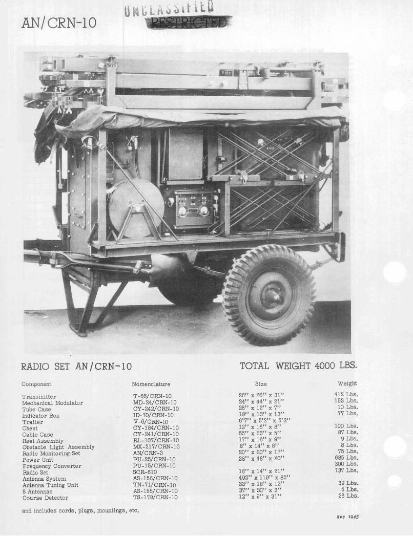
RADIO SET AN / CRN- 10 TOTAL WEIGHT 4000 LBS.
Component
TransmitterMechanical ModulatorTube CaseIndicator BoxTrailerChestCable CaseReel AssemblyObstacle Light AssemblyRadio Monitoring SetPower UnitFrequency ConverterRadio SetAntenna SystemAntenna Tuning Unit8 AntennasCourse Detector
Nomenclature
T-66/CRN-10MD-24/CRN-10CY-242/CRN-10ID-70/CRN-10V-6/CRN-10CY-184/CRN-10CY-241/CRN-10RL-107/C R- 10MX-217/CRN-10AN/CRN-3PU-25/CRN-10PU-15/CRN-10SCR-610AS-156/CRN-10TN-71/CRN-10AS-155/CRN-10TS-179/CRN-10
Size
26" x 26" x 31"24" x 44" x 21"25" x 12" x 7"19" x 13" x 13"6'7" x 5'2" x 5'3"12" x 16" x 8"55" x 23" x 5"17" x 16" x 9"8" x 14" x 6"20" x 20" x 17"28" x 48" x 20"
16" x 14" x 51"492" x 119" x 85"33" x 18" x 12"37" x 30" x 3"12" x 9" x 31"
and includes cords, plugs, mountings, etc.
Weight
412 Lbs.153 Lbs.
10 Lbs.77 Lbs.
100 Lbs.87 Lbs.
9 Lbs.8 Lbs.
75 Lbs.685 Lbs.300 Lbs.137 Lbs.
39 Lbs.5 Lbs.
26 Lbs.
Nmy 1945
,U,
91 ; BA

AN/ CRT-3
Radio Set AN/CRT - 3 is an air-transportable,hand-powered emergency transmitting system designed foroperation from a rubber life raft and to serve as an aid tosea rescue. It consists of a modified SCR-578-A and oper-ates on the international distress frequency of 500 kc.
AN/CRT-3 also operates on a frequency of 8280kc. with a 1000 cycle MCW note on 500 kc. and CW emissiononly on 8280 kc. Transmission is automatically shiftedevery 40 seconds from one frequency to the other. Oper-atibnal manual keying on the international distress frequencyis provided. When manually keyed, the transmitter oper -ates only on the international distress frequency. The fre-quency shifting mechanism is then inoperative.
Use of 8280 kc. provides a means of obtaininglong range bearing from landbased direction linding stationsso that ships or aircraft can be dispatched to the generallocation, and the 500 kc. transmitter is used by the rescuecraft to home on the life raft. On test using the 8280 kc.frequency, satisfactory bearings have been obtained up to1,600 miles. Included in the equipment is a parachute topermit dropping of the set into the sea without damage.
Test equipment for maintenance is under devel-opment.
Army Supply Program requirements for AN/CRT-3 and/or SCR-578 as of 31 October 1944 were 40,742equipments for the calendar year 1944 and 43,023 for 1945.
Radio Set AN/CRT-3 packed with parachute M-340-A attached.
TUBE COMPLEMENTNO. TYPE I NO. I TYPE1 12A6 1 12SC7
Front View of Radio Transmitter T- 74(XA-A)/CRT-3(XA-2)
Nay 1945
POWER INPUT HAND CRANKEDFREQUENCY 500 KC. & 8280 KC.TYPE OF SIGNAL MCW FOR 500 KC. CW
FOR 8280 KCRANGE 200 MILES AT 500 KC.
1600 MILES AT 8280 KCDUAL FREQUENCY 40 SECONDS

AN/CRT-3
Radio TransmitterT-74(XA-A)/CRT-3(XA-2)
BalloonsM-278-A
Inflating Tubes
ParachuteM-390-A
Signal LampM-308-B
Antenna Reels
Inner Bag
Bag BG-155-A
GeneratorsM-315-B
KiteM-357-A
RADIO SET AN / CRT-3 TOTAL WEIGHT
Component
Radio TransmitterAntenna AssemblySignal LampKiteBalloonGeneratorParachuteBagLamp
*less than one pound.March 1945
Nomenclature
T-74/CRT-3AS-2Q7/CRT-3. (2 each)M-308-BM-357-AM-278-AM-315-BM-390-ABG-155-ALM-58-A
Size
10" x 14" x 9"3" x 3" Diam.2" x 3" Diam.18" x 4" Diam.5" x 4" Diam.12" x 4" Diam.9" x 9" x 5"20" x 17" x 14"
3 2 LBS.
Weight
16 Lbs.**
1 Lb.1 Lb.3 Lbs.3 Lbs.7 Lbs.

r f . "'' "" r
AN/MRN-1
Radio Set AN/MRN-1 is a portable multi-fre-quency instrument approach localizer, a part of the AAFInstrument Approach System. The function of the equip-ment is to provide a signal to guide an RC-103 equippedairplane to the line of a runway. It furnishes signals fororienting an airplane in the horizontal plane to provide posi -tioning along the centerline of the landing runway. Other com-ponents of the Army Air Force Instrument Approach Systemfurnish signals for orienting an airplane in the verticalplane (glide path) to provide a path for descent, and mar-ker beacon signals to indicate the position of an airplanewith relation to the location of the landing strip. The equip-ment is installed in a K-53-D truck.
The set radiates two intersecting field patterns,one of which is modulated at an audio frequency of 90 cy-cles per second and the other at an audio frequency of 150cyles per second. The shape of the radiated patterns issuch that they intersect in a vertical plane, called the'Course', which can be oriented (by cositioning the truck)to intersect the ground in a line which coincides with thecenter line of a landing runway. A localizer receiver-equipped airplane is thereby provided a course to be flownto a predetermined runway under conditions of poor visi-bility.
The range of the equipment is a function of theelevation of the receiving antenna; approximately 40 milesat an elevation of 2,500 feet; 70 miles at 6,000 feet; and100 miles at 10.000 feet.
Radio Set AN/MRN- 1 has a frequency range from108.3 to 110.3 mc., and may be operated on any frequencywithin that range by merely inserting the proper crystalunit and properly tuning Radio Transn'itter BC-751- A.Six Crystal Units DC-17-A are provided for operation on108.3, 108.7, 109.1, 109.5, 109.9 and 110.3 me. Althoughthe equipment is designed for operation on six frequencies
Radio Transmitter BC-751 installed in truck.
the frequencies assigned for instrument approach use are108.7, 109.5and 109.9 me. Power is furnished from a 115volt, 60 cycle source.
As used by the 13th and 14th Air Forces in theCBI theater, with the upper antenna array mounted on a70-foot support to project the beam over mountainous ter-rain, its range is 100 miles at 10,000 feet altitude. It isused as a navigational aid for cargo airplanes flying overthe "hump."
* Radio Set AN/ CRN-10, a portable localizer trans-mitter will ultimately replace the AN/MRN-1 since it pro-vides the same type of signals, is of reduced size and weight,and has improved antenna pattern which reduces the en-ergy in reflecting objects to the rear of the localizer.
Test equipment required for maintenance andtuning is contained in the parts list for the equipment.
As of 1 February 1945 there were no require-Indicator BC-777 installed in truck. ments on the Army Supply Program.
May 1945

AN/ MRN-1
Course Detector BC-753 is generally placed well away from and parallel to antenna equipment RC-109.May 194 5
POWER INPUT 1250 WATTS@115 VOLTSPOWER OUTPUT CW & VOICE-100 WATTS
PEAKMCW-25 WATTS PEAK
FREQUENCY 108.3-110.3 MC.TYPE OF SIGNAL CW, MCW & VOICERANGE 40 MILES @ 2500 FEET
ALTITUDE--70 MILES@6000 FEET ALTITUDE100 MILES @ 10,000FEET ALTITUDE
TUBE COMPLEMENT
NO. TYPE NO. TYPE1 9002 2 6H61 6SF5 2 20511 6K6GT/G 4 8071 6X5GT/G 3 4E271 1R5 1 6F61 957 1 6SN7GT2 1LN5 1 5V4G1 1S5 4 8361 3S4 2 VR-150-30
ReSIRIFIEB

;sa ir 11~3 :Rt 1u W
REFLECTOR SCREENPREVENTS BACKCOURSE AND ECHOESFROM cUILDiNGSAND TERRAIN
Radio Scl AN/MRN-1 is a portable multi-frequency instrument landing localizer used in conjunction withAirborr e Radio Receiving Equipment RC-103-A,.-AZ. It transmits a forward course beam which enablesapproaching aircraft to establish lateral alignment with the runway.
May 1945
AN/MRN-1

AN/MRN-1
RADIO SET AN/MRN-1
Component
Control BoxCourse DetectorCourse DetectorFuel PumpHeaterIndicator BoxJunction BoxJunction BoxModulator & BridgePower UnitRadio TransmitterRange PolesMaintenance Parts in ChestTool EquipmentTruckRadio SetRadio Monitoring SetAntenna Equipment
TOTAL WEIGHT
Nomenclature
BC-915-ABC-753-ABC-754-A
M-321-ABC-777-AJB-58-AJ-7/MRN-1BC-752-APE-141-ABC-751-AM-382-ACH-181
K-53-DSCR-610AN/CRM-3RC-109
Size
24" x 14" x 8"20" x 13" x 22"32" x 10" x 8"22" x 6" diam.69" x 13" x 14"19" x 14" x 13"15" x 10" x 4"7" x 6" x 3"47" x 33" x 23"49" x 37" x 21"47" x 31" x 28"72" long65" x 37" x 22"17" x 11" x 6"252' x 116' x 93'
226" x 48" x 34"
and includes cables, mountings, batteries, cords, etc.
16,900 LBS.
Weight
49 Lbs.65 Lbs.24 Lbs.13 Lbs.
120 Lbs.60 Lbs.
8 Lbs.3 Lbs.
330 Lbs.804. Lbs.549 Lbs.
4 Lbs.851 Lbs.24 Lbs.
11,700 Lbs.137 Lbs.
564 Lbs.
May 1945
~~~hnbil~ltD

~g 1--1k 1 C d $. I5;
Radio Set AN/MRN-2 is a ground, mobile, two-course VHF aural radio range with station identification,periodic sector identification and simultaneous voice trans-mission. It is a crystal controlled set and operates in thefrequency range of 100 to 156 mec. for use in guiding air-craft equipped with VHF communications receivers, suchas Radio Set SCR-522, to landing field, or for use in flyingferry routes.
Adjustable overthefrequ icy band of 100 to 156mc., operation without readjustment is limited to a bandof 5 mc. The equipment, including the antenna, can be re-adjusted to any frequency within one-half to one hour pro-vided the necessary crystals are available. The selectionof operating frequency depends on the proposed use of theequipment.
Considerable attention to siting the VHF radiorange equipment is required. The use of vertical polari-zation gives rise to some reflection from trees within 500feet of the radio range site. Thus it must be located in acleared space of 500 feet radius. To obtain nearly perfectcourses a cleared space of 1,000 feet radius is recom-mended.
Extensive flight tests indicate that course bendsproduced by the location of Radio Set AN/MRN-2 in moun-tainous terrain are not too severe to make its operationunsatisfactory; bends produced by location of the trans-mitter in a valley are more severe thanthose produced byits location on top of a mountain; location ontop of a moun-tain greatly increase- distance range obtained; and oper -ation of the voice modulation channel is very satisfactory.Power for operation is furnished by a 2 KVA gasoline drivenpower unit.
TUBE COMPLEMENT
NO. TYPE NO. TYPE
1 6B8 4 8073 6H6 2 8292 6J5 2 8322 6SJ7 6 8363 6SN7GT 1 20503 6V6GT 1 OD3/VR-1502 6X5GT 1 6SK7GT/G
Range Transmitters installed in forward part of truck.Test equipment required for maintenance and
tuning is furnished with the basic equipment.There were no Army Supply Program require-
ments as of 1 February 1945.
POWER INPUT 200 WATTS @ 115 VOLTS60 CYCLES
POWER OUTPUT CONE OF SILENCE-25WATTS: TRANSMITTERCARRIER - 100 WATTSSIDE BAND -50 WATTS
FREQUENCY 100-156 MC.TYPE OF SIGNAL CW: MCW: VOICERANGE 100 MILESANTENNA POLARIZATION VERTICAL
Radio Set AN/MRN-2, a ground, mobile two course VHF aural radio range, provides station identification,periodic sector identification and simultaneous voice transmission.
May 1945
AN/MRN-2

AN/MRN-2
RADIO SET AN /MRN- 2 TOTAL WEIGHT 13,500 LBS.
Component
AmplifierAntennaMonitorPhaserPower Control UnitPower UnitRadio TransmitterRectifier ModulatorTest SetVoltmeterAntenna BaseCompass AssemblyTruck
Nomenclature
AM-11/CRN-5AT- 7/CRN-5TS-22/URNCU- 3/C RN-5C-49/CIRN-5PU-3/CRN-5T-10/ CRN- 5MD-3/CRN-51-77-ATS-21/CRN-5AB-1/CRN-5B-16K-53-D
Size
10" x 6" x 4"135" x 6" diam.8" x 6" x 29"5" x 13" x 44"30" x 14"18" x 36" x 31"62" x 23" x 18"62" x23" x18"4" x 3" x 7"4" x 5" x 12"8" x 10" x 24"
Weight
14 Lbs.46 Lbs.11 Lbs.41 Lbs.41 Lbs.
460 Lbs.384 Lbs.561 Lbs.
2 Lbs.3 Lbs.
2 Lbs.11,700 Lbs.
May 1945
A S

Marker Beacon Set AN/MRN-S is a jeep-mountedtransmitter providing a vertical fan-shaped pattern forboundary marking and a channel for communication withthe airport control tower.
AN/ MRN-3 replaces the Instrument LandingEquipment SCR-241 in the AAF Instrument Approach Sys-tem. Each system requires three marker beacon sets, oneto be located in the airport runway boundary, one at appro-simately one mile from the approach end of the runway andone 4 1/2 miles from the approach end of the runway all onthe center line of the runway to be used,
The equipment transmits a vertical pattern to bereceived by Marker Beacon Receiving Equipments RC-39,RC-43, RC-193-(), AN/ARN-8 or AN/ARN-12, markingreference points inthe instrument landing system. A sig-nal amplitude modulated at 1300 cycles per second, maybe keyed at two dashes per second, six dots per second ormay be unkeyed. A power input of 125 watts from a powersource of 115.volts 60 cycles per second is required foroperation.
The marker beacon transmitter projects a verti-cal fan-shaped pattern to a height of approximately 3,000feet. The transmitter is placed so that the longer hori-zontal axis of the beam is perpendicular to the line of ap-proach. A pilot flying through the marker signal at analtitude of 900 feet and a speed of 120 miles per hour will
AN/MRN-3
receive an indicationfrom his marker beacon receiver forapproximately 12 seconds. Flying through the same patternat 200 feet (speed 120 miles per hour), he will receive anindication for approximately 6 seconds.
Test equipment required for maintenance in-cludes Maintenance Equipment ME-l3.
Army Supply Program requirements as of 1 Feb-ruary 1945 were 497 equipments for the calendar year 1945.
POWER INPUT 125 WATTS@115 VOLTSA.C.
POWER OUTPUT 1 WATTFREQUENCY 75 MEGACYCLESTYPE OF SIGNAL MCWRANGE 13,000 FEET VERTICAL
TUBE COMPLEMENT
NO. TYPE NO. TYPE
1 5Z4 2 12912 VR-150-30 4 12991 7E6 1 1LH42 7E7 1 12941 7N7 1 lLC65 7C5 1 10055 lLN5
The Airborne Marker Beacon receiver picks up and records on an indicator lamp (pilots position) thetransmissions of the respective marker beacons Thus oienting the approaching aircraft (in distance)to the runway
May 1945
UNCLASSIFIED

AN/MRN-3 UNCLASSIFIED
1.Radio Transmitter BC-902-B 2.Radio Set SCR-610-A 3.Power Unit PE-88 4.Shelter S-2/MRN-3 5.Roll BG-56
MARKER BEACON
Component
ShelterPower UnitRadio Transmitting EquipmentRadio SetTruck
SET AN/MRN-3
Nomenclature
S-2/MRN-3PE-88-ARC-115-ASCR-610
Size
56" x 4" x 28"20" x 10" x 16"43" x 18" x 23"
1/4 ton 4' x 4'(jeep)
and includes maintenance kit for power unit PE-88-A.
TOTAL WEIGHT 2600 LBS.
Weight
85 Lbs.60 Lbs.
140 Lbs.
May 1945

UNCLA
Beacon Receiver BC-1206 is a small, airborne,light-weight superheterodyne receiver having a frequencycoverage of 200 to 400 kc. for use in connection with radiobeacon transmitters.
By receiving a signal from the beacon trans-mitters on the ground, BC-1206 indicates by aural signalthe aircraft's position in relation to right or left bearingof thetransmitter.' Installed infighter aircraft, the equip-ments are intendedfor use inthis countryand are removedfrom the aircraft prior to entering combat overseas.
Beacon Receivers BC-1206-A, B. C and Dareessentially the same with the exception of minor electricaldifferences.
No special test equipment is required for main-tenance.
BEACON RECEIVER
Component
Detrola Receive Model
and includes cable and connectors.Nay 1945
BC-1206
Nomenclature
Model 438
SSIFIED BC -1206
Army Supply Program requirements as of 1 Feb-ruary were 11,860 receivers forthe calendaryear 1945, and23,599 for 1946.
POWER INPUTFREQUENCYTYPE OF SIGNALRANGE
24 WATTS 28195-405 KC
VOICE & MCW150 MILES
VOLTS
TUBE COMPLEMENT
NO. TYPE NO. TYPE
2 14A7/12B7 1 14R71 14J7 1 28D7
TOTAL WEIGHT
Size
5" x 5" x 8'"
5 LBS.
Weight
4 Lbs.

Marker Beacon Receiving Equipment RC-43-A,an ultra-high frequency receiving equipment used in air-craft as an aid to navigation and landing, provides visualindication when flying over a 75 mc. marker beacon.
Operating in the frequency range of 67-80 mc.,RC-43-A is designed to receive the 75 mc. marker beaconsignals used in the AAF Instrument Approach System andthe cone of silence and fan marker beacons of the CivilAeronautics Administration, and other facilities employingmodulated 75 mc. horizontally polarized transmission.
When the receiver is over a transmitter oper-ating on a frequency within the receiver's limits, an indi-cator lamp on the instrument panel of the aircraft givesvisual signal to the pilot in accordance with the output ofthe receiver. When over a "keyed" transmitter, such asa CAA marker, or certain types of army transmitters, theindicator lamp flashes in definite sequence, identifying thetransmitter.
Plate voltage supply is obtained from the radiocompass power supply, and is controlled simultaneouslywith the power to the compass.
Marker Beacon Receiving Equipment RC-39-Aconsists of equipment similar to RC-43-Awiththe exceptionof the filament voltage which, in the RC-39-A is 12 volts,instead of 24 volts as in RC-43-A.
There were no Army Supply Program require-ments as of 31 January 1945.
POWER INPUT 24 VOLTSFREQUENCY 67 TO 80 MC.TYPE OF SIGNAL 75 MC. CARRIER
MODULATED WITH400. 1300 or 3000CYCLES
RANGE 12.000 FT. OVER CONEMARKER16,000 FT. OVER FANMARKER
PC- 43-A
As Aircraft passes through area of Marker Beacon Trans-missionthe Impulse is received and recorded by IndicatorLamp on Instrument Panel, Pilot's Position.
TUBE COMPLEMENT
NO. TYPE FNO. TYPE
1 12SQ7 1 12C8 Special
Radio Receiver BC-357-M
MARKER BEACON RECEIVING EQUIPMENT
Nomenclature
RC-43-ATOTAL WEIGHT
Size
Radio ReceiverMountingInsulator (2 ea.)
BC-357-()U/WRC-43-AFT-161IN-88
6' x6"x4"6" x 6" x 2"5'' x 1'
*Less than one sound.and includes plugs, terminals, couplings, cables, antenna wire, etc.May 1945
UNCLASSIFIED
Component
7 LBS.Weight
3 Lbs.*

IJMLASSIFIFPRC-103-A
Radio Receiving Equipment RC-103-A is an air-borne localizer receiver used to indicate a landing coursein conjunction with the AAF Instrument Approach System.Signals received from a transmitter, located at one end ofthe runway to be used, are fed into the cross-pointer indi-cator to indicate "on course", "fly right" or "fly left."Audio indication is also provided.
The equipment operates from a 28 volt d.c. powersource. RC-103-AZ is similar to RC-103-A except thatit operates from a 14 volt d.c. power source.
Crystal control is provided for operation on sixfixed frequencies between 108.3 and 110.3 me.
Antenna System AS-27/ARN-5 is used with thedual installation of the localizer and glide path receivers.Antenna AN-100 is used when only the localizer receiveris installed in the aircraft.
Test equipment used in maintenance and tuningincludes Test Set I-173 and Test Set TS-67/ARN-5.
Army Supply Program requirements as of 1 Feb-ruary 1945 were 33,856 equipments for the calendar year1945 and 19,730 for 1946. The VerticalPointerof Indicator I-101 records position oa
aircraft with regard to alignment to runway.
TUBE COMPLEMENT
NO. TYPE NO. TYPE1 12A6 1 12SQ71 12AH7GT 2 12SR72 12SG7 3 717A
Radio Receiving Equipment RC-103 is an Airborne Receiver used in conjunction with a Ground LocalizerTransmi ter to align incoming aircraft with landing strips.
Nay 1945

iLURC- 103-A
Indicator I-101-C
Radio Control Box BC-732-A
Dynamotor DM-53-A
Antenna AN-100
RADIO RECEIVING
Component
Indicator.DynamotorMountingMountingRadio Control BoxRadio ReceiverAntennaAntenna System
SET RC-103-A
Nomenclature
I-101-()DM- 53-AZFT-293-AFT-292-ABC-732-ABC-733-DAN-100-()AS-27/ARN-5
TOTAL WEIGHT 36 LBS.
Size
Diam. 3 1/4 Depth 3 1/45" x 3" x 3"13" x 6" x 2"4" x 3" x 1"3" x 4" x 3"13" x 5" x 7"
10" x 20" x 15"
and includes adapter, set of crystals and spare vacuum tube set.*Less than one pound.
Weight
3 Lbs.3 Lbs.2 Lbs.*
1 Lbs.21 Lbs.4 Lbs.2 Lbs.
May 1945
UNCLA
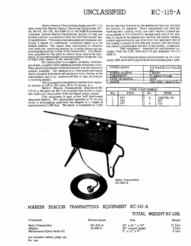
Marker Beacon Transmitting Equipment RC-115,when used with Marker Beacon Receiving Equipments RC-39, RC-43, RC-193, AN/ARN-12 or AN/ARN-8 constitutescomplete marker beacon transmitting facility for any oneground position inconnection with the AAFInstrument Ap-proach System. This equipment generates and radiates ver-tically a keyed, or -continuous, modulated signal in a fanshaped pattern. The signal thus transmitted is effectiveonly when the receiving antenna is directly above and ap-proximately parallel to that of the transmitter. It is, there-fore, possible for the pilot to obtain visual and aural indi-cation of his approximate horizontalo position along his lineof flight with respect to the landing field.
The transmitter is a rugged,.portable, weather-proof unit, complete with radiating antenna and power cord.The controls accessible to field personnel are the minimumnumber possible. The antenna ,is a removable half-wavedipole mounted with stand-off insulators from the top of thetransmitter, and is so constructed that it may be used asa carrying handle.
The equipment is designed to operate from a pow-er source of 105 to 135 volts, 50 to 70 cycles, a.c.
Marker Beacon Transmitting Equipment RC-115-B is the same as RC-115-A except that ituses a crys-tal-controlled transmitter with increased power output.
This equipment is part of the AAF InstrumentApproach System. The transmitted operates at 75 me andemits a horizontally polarized fan-shaped to a height ofapproximately 7,560 feet. The signal is modulated at 1,300
SSIFIED RC-115-A
cycles and may be keyed at two dashes per second, six dotsper second, or unkeyed. Three equipments are used formarking each landing strip; the outer marker located ap-proximately 4 1/2 miles from the approach end of the run-way is keyed at two dashes per second; the middle markerlocated approximately one mile from the approach end ofthe runway is keyed at six dots per second; and the bound-ary marker, located near the end of the runway, is unkeyed.
Test equipment required for maintenance in-cludes Test Set 1-56, Test Set I-76 and Indicator ID-101/MRN-3
Army Supply program requirements as of 1 Feb-ruary 1945 were 200 equipments for the calendar year 1945.
POWER INPUT 112 WATTS: 115 VOLTSAC.
POWER OUTPUT 1 WATTFREQUENCY 75 MEGACYCLESTYPE OF SIGNAL MCWRANGE 7500 FEET VERTICAL
TUBE COMPLEMENT
NO. TYPE NO. TYPE
1 5Z4 2 OD3/VR-1501 7E6 1 7N72 7F7 5 705
Radio TransmitterBC-902-B
TRANSMITTING EQUIPMENT RC-115- A
Component
Radio TransmitterAdapterMaintenance Spare Parts Kit
and includes cables, plugs etc.Nay 1945
Nomenclature
BC-902-BM-268-A
TOTAL WEIGHT 60 LBS.Size Weight
22" x 43 " x 18"20" overall length5" x 11" x 5"
51 Lbs.2 Lbs.5 Lbs.
MARKER BEACON
iJLNJ:&[ ASSIFrFRC-193-A
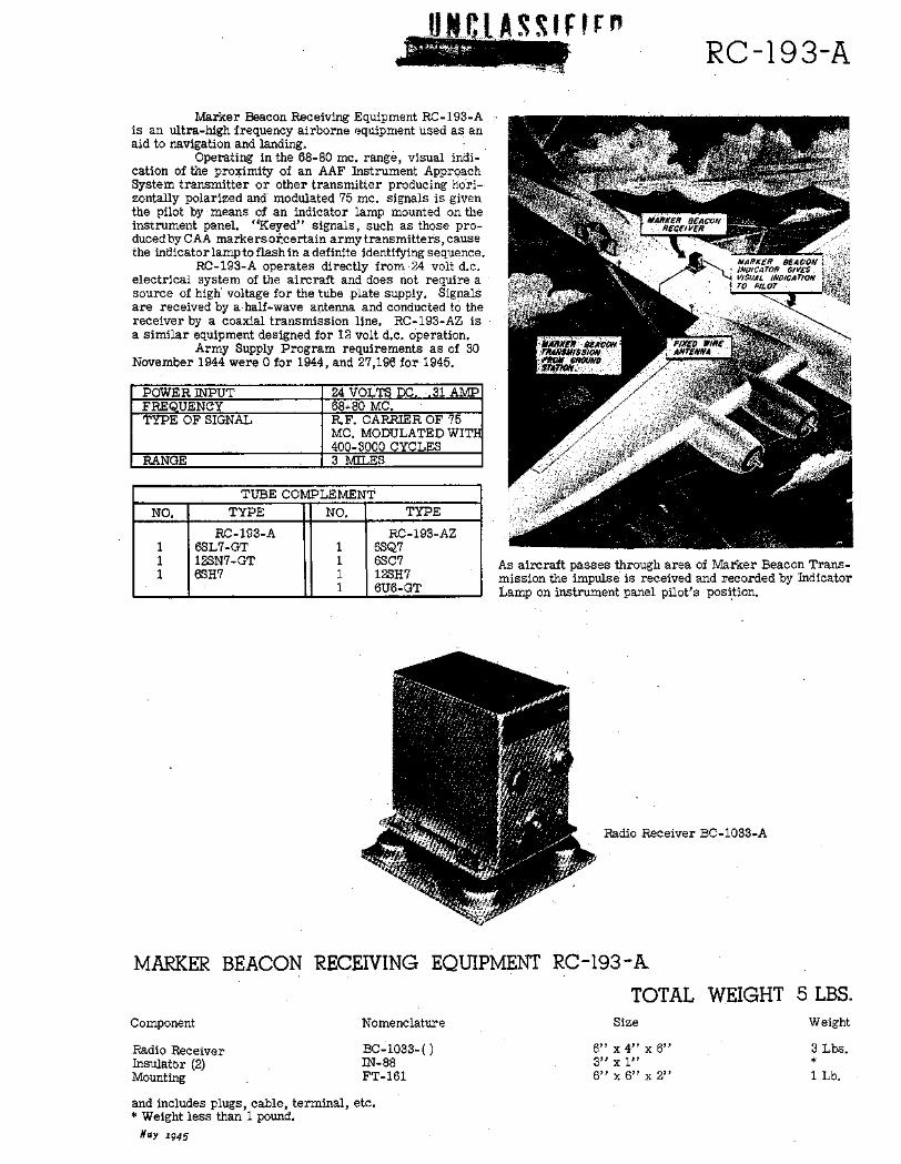
Marker Beacon Receiving Equipment RC-193-Ais an ultra-high frequency airborne equipment used as anaid to navigation and landing.
Operating in the 68-80 mc. range, visual indi-cation of the proximity of an AAF Instrument ApproachSystem transmitter or other transmitter producing hori-zontally polarized and modulated 75 mc. signals is giventhe pilot by means of an indicator lamp mounted on theinstrument panel. "Keyed" signals, such as those pro-duced by CAA markers oicertain army transmitters, causethe indicator lamp to flash in a definite identifying sequence.
RC-193-A operates directly from 24 volt d.c.electrical system of the aircraft and does not require asource of high' voltage for the tube plate supply. Signalsare received by a half-wave antenna and conducted to thereceiver by a coaxial transmission line. RC-193-AZ isa similar equipment designed for 12 volt d.c. Operation.
Army Supply Program requirements as of 30November 1944 were 0 for 1944, and 27,196 for 1945.
POWER INPUT 24 VOLTS DC. ~31 AMPFREQUENCY 68-80 MC.TYPE OF SIGNAL R.F. CARRIER OF 75
MC. MODULATED WITH400-3000 CYCLES
RANGE 3 MILES
TUBE COMPLEMENT
NO. TYPE NO. TYPE
RC-193-A RC-193-AZ1 6SL7-GT 1 6SQ71 12SN7-GT 1 6SC71 6SH7 1 12SH7
S1 6U6-GT
As aircraft passes through area of Marker Beacon Trans-mission the impulse is received and recorded by IndicatorLamp on instrument panel pilot's position.
Radio Receiver BC-1033-A
MARKER BEACON RECEIVING EQUIPMENT RC-193-A
Component
Radio ReceiverInsulator (2)Mounting
Nomenclature
BC-1033-()IN-88FT-161
TOTAL WEIGHTSize
6" x 4" x 6"3" x 1"6" x 6" x 2"
and includes plugs, cable, terminal, etc.* Weight less than 1 pound.
Nay 1945
5 LBS.Weight
3 Lbs.*
1 Lb.
UNCLASSIFIED RC-198
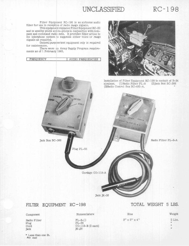
Filter Equipment RC-198 is an airborne audiofilter for use in reception of radio range signals.
This equipment replaces FilterEquipment RC-32and is used by pilots and co-pilots in conjunction with com-pass and command radio sets. It provides filter action tothe interphone system to suppress either voice or rangesignals as required.
General purpose test equipment only is requiredfor maintenance.
There were no Army Supply Program require-ments as of 1 February 1945.
FREQUENCY AUDIO FREQUENCIES
Installation of Filter Equipment RC-198 in cockpit of B-34airplane. (1)Radio Filter FL-8 (2)Jack Box BC-366(3)Radio Control Box BC-450-A.
Radio Filter FL-8-A
TOTAL WEIGHT 5 LBS.
Nomenclature
FL-8-()PL-55CO-119-B (2 each)JK-26
* Less than one lb.Nay 1945
FILTER EQUIPMENT RC-198
Component
Radio FilterPlugCordJack
Size
3" x 3" x 4"
Weight
2 Lbs.*

Filter Equipment RC-210 is an airborne audiofilter designed to isolate either voice or range signal duringperiods of simultaneous reception of these signals.
This equipment is used by pilots and co-pilotsin conjunction with compass and command radio sets. It isnot a part of any radio set but may be used with any stand-ard radio receiver connected for low impedance operation.
A three position switch ontop of this filter boxmarked VOICE-RANGE-BOTH provides selection. Whenthe selector switch is in the VOICE position, a 1020 c.p.s.band reject filter is placed in the circuit. This filter greatlyattenuates the 1020 cycle range tone, and passes thevoice frequencies, other than those in the 800-1200 c.p.s.band, with only a slight amount of attenuation. When the
Jack BoxBC-1366-M
Plug PL-55
Cordage O-119-Aor CO-119-B
FILTER EQUIPMENT' RC -210
si N r,
Radio FilterFL-30
TOTAL WEIGHT 5 LBS.
Nomenclature
FL-30-()JK-26PL-55CO-119-A(-B)
*Less than one pound.May 1945
Component
Radio FilterJackPlugCordage
Size
3" x 3" x 4
Weight
2 Lbs.
i S S 161RC-.210
switch is in the RANGE position, a 1020 band pass filteris placed in the circuit, and rejects practically all the voicefrequencies. Inthe BOTH position, both the band pass endand band reject filters are disconnected from the circuit.Therefore, the signals are not affected by the filter.
FilterEquipment RC-2l0 is designed to operatewith a 600 ohm load. Headsets HS-33 or HS-38 offer im-pedance of 600 ohms.
Army Supply Program requirements as of 31January 1945 were 69,628 equipments for the calendaryear 1945 and 48,866 for 1946.
FREQUENCY AUDIO FREQUENC S
i r

UNCLAD
Radio Compass SCR-269-G was primarily de-signed to be used as a navigational instrument in army air-craft. Basically, the equipment is a radio receiver em-ploying a superheterodyne circuit and certain additionalessential circuits necessary for radio compass operation.Two remote controls are provided, and, although only onecontrol functions at a time, control may be readily switchedfrom one to the other.
The equipment has a frequency range of 200 kcto 1750 kc, covered in three bands, and calibrated in kilo-cycles. Only the frequency band in use is visible on thetuning scale. Radio Compass SOR-269-G is manually tunedfrom either of two remote positions, with the bands switchedelectrically from the position having control. When instal-lations are made which use only one remote control, noswitching of control is necessary andthe one radio controlbox used has control at all times.
When used in conjunction with a suitable non-directional (vertical) antenna, a 14 or 28 volt do supply,one or two headsets, and necessary interconnecting wiring,Radio Compass SCR-269-G is a complete operable unitcapable of providing the pilot with automatic bearing indi-cation of the direction, relative to the line of flight, of thetransmitter creating the received signal. Also, by use ofa loop antenna, aural-null directional indications of a trans-mitted signal may be obtained. Aural reception of modu-lated radio frequency signals is possible with either thevertical or loop antenna, and aural reception of unmodu-lated signals is possible in each of the four cases. Selectionof either type of reception is made by use of a C.W-VOICEswitch.
There were- no Army Supply Program require-ments as of 31 January 1945, since Radio Compass AN/ARN-7, covering the 100-200 kc band in addition to the200-1750 kc coverage of SCR-269-G, more nearly meetsa military requirement for a compass adaptable for long
SIFIED SCR-269-G
range operation in connectionwith established low frequencytransmitters in many parts of the world. Radio CompassAN/ARN-6, in development, is intended as the eventualreplacement of both SCR-269-G and AN/ARN-7 in armyaircraft.
Test equipment forSet -56-A and Test Set I-100.
SCR-269-G includes Test
POWER INPUT 0.5 AMPERES @ 28VOLTS DC115-140 VOLTS, 400CPS;_AC
POWER OUTPUT 600 MILLIWATTS PEAKFREQUENCY 200-1750 KC IN 3
BANDS
TYPE OF SIGNAL CW; MCW; VOICESIGNAL STRENGTH 40-50 MICROVOLTS
PER METER
ANTENNA 8" LOOP AND FIXEDVERTICAL MAST WITHONE OR TWO REMOTECONTROL POSITIONAND AUTOMATICROTATION
SENSITIVITY 3.5 MICROVOLTSSELE CTIVITY 4.5-13 KO
TUBE- COMPLEMENT
NO. TYPE NO. TYPE
2 6F6 1 6J51 5Z4 1 6N74 6K7 1 6SC71 6L7 2 20512 6B8
In additic 1 to its high frequency band of 2800 to 5900 kc.. Radio Compass SCR-269-G provides facilities forhoming and plotting of aircraft positions similar to those of other Automatic Radio Compasses.
May 1945

SCR- 269-G UNCLASSIFIED
Radio Control Box BC-434-A
Radio Compass Unit BG-433-G
Indicator 1-81-A Indicator 1-82-ADehydrator Hose
Relay BK-22-E
RADIO COMPASS
Component
Radio Compass UnitRadio Control BoxLoopIndicatorIndicatorRelayRectifier Unit
SCR- 269 -G
Nomenclature
-BC-433-GBC-434-ALP- 21-A1-81-A (Pilot's)1-82-A (Navigator's)BK-22-A or ERA- 59-A
TOTAL WEIGHT 98 LBS.
Size
20" x 12" x 8"8" x 8" x 4"25" x 9" x 15"4" x4" x4"5" x5" x5"12" x7" x 3"7" x5" x4"
and includes cords, conduits, etc.
I
Dehydrator
Weigtt
46 Lbs.4 Lbs.
10 Lbs.1 Lb.2 Lbs.6 Lbs.6 Lbs.
May 1945

0i (LA5SIfi1DSCR-277
Radio Set SCR-277 is a mobile ground radio rangetransmitter used to set up ranges at regular intervals alongair routes to provide beacon facilities for navigation ofaircraft from point to point. The equipment is mounted ina trailer type K-29-C, to provide portability.
In operation the transmitter sends out signalscoded "A" or "N" in each of the four quadrants aroundthe beacon. The signals overlap on the range, providingthe pilot of the aircraft an indication of his position in re-lation to location of the beacon. Thus, if he is headingtoward the beacon he will receive an aural signal coded"A" or "N" if he is between the beam, and when he is onthe beam he will receive an "AN" signal. Overland areasthe beaconhas a range of about 300 miles, while over waterareas the range is extended to about 1,000 miles. Chartsprepared for air navigation show the position and the orien-tation of the various beacons.
Power for operation of the equipment is furn-ished by a gasoline driven power unit that provides 7.5kilowatts at 115 volts and 500 cycles per second, and twosix volt storage batteries.
Test equipment required for maintenance in-cludes Tool Equipment TE-60 and Test Set 1-77.
Army Supply Program requirements as of 1 Feb-ruary 1945 were 11 equipments for the calendar year 1945.
TUBE COMPLEMENT
NO. TYPE NO. TYPE
2 6C5 2 8071 6F6 1 8144 6K7 1 -128-A1 6L7 1 5A31 6R7 2 866/866A1 5W4 2 872-A
Radio Range SCR-277 set up for operation.
POWER INPUT 7.5 KW@110 VOLTSPOWER OUTPUT 810 WATTSFREQUENCY 200-400 KC.TYPE OF SIGNAL CW: WRANGE LAND-300 MILES;
WATER-bOOMILESANTENNA CROSSED LOOPS 70
______________FEET HIGH
Radio Set SCR-277 is a portable low frequency 1oop radio range - providing a 4 course range with facilities forvoice transmission and periodic station identification.
Nay 1945

UNCLASSIFIEDSCR-277
RADIO SET SCR-277 TOTAL WEIGHT 7000 LBS.
Nomenclature
AntennaAntennaAntenna Tuning UnitAuxiliary Control BoxBatteries, storageControl BoxFire ExtinguisherGoniometer UnitMastPolePole ExtensionPower UnitRadio TransmitterReelTrailerRadio ReceiverAntennaHeadsetTest SetTool Equipment
AN-33(horizontal)4 eachAN-34(sloping)4 eachBC-469-C
(2 each)BC-466-C
BC-468-CMA-4-CMS-75 (3 each)MS-90 (3 each)PE-90-CRC-467-CRL-40K-29-CBC-342-()AN-19P-19I-77TE-60
148' long164' long33" x 24" x 16"9" x 5" x 3"16" x 8" x 10"10" x 9" x 7"23" x 8" x 7"44" x 22" x 29'.'76' x 7" diam.144" x 4" x 2"44 ' long x 2" dianm.51" x 36" x 35"49" x 54" x 22"13" x 9" x 10"200" x 76" x 107"19" x 10" x 10"62' long
6" x 4" x 3"
and includes cords, cables, clamps, accessories, spare parts, etc.May 1945
Component Size Weight
58 Lbs.60 Lbs.
141 Lbs.4 Lbs.
158 Lbs.19 Lbs.35 Lbs.
235 Lbs.250 Lbs.
17 Lbs.17 Lbs.
1075 Lbs.555 Lbs.
5 Lbs.3359 Lbs.
61 Lbs.2 Lbs.2 Lbs.2 Lbs.

J t .; iA
SCR-578
Radio Set SCR-578 is a simple, rugged emer-gency transmitting system designed for operation from alife raft. No receiving equipment is incorporated in theset. The set provides automatic code transmission of pre-determined signals so that any operator, with or withouttraining, can send distress signals which, when receivedby rescue parties, will permit bearings to be taken. Theset operates on the international distress frequency of 500kc. with a 1000-cycle tone modulation.
It may be used as a hand-powered signal lightwith manual keying to transmit instruction, or as a con.-stant signal light. If the signal light is used, no radio trans-mission takes place.
Various models of the transmitter differ only indetails of electrical or mechanical design. AKite M-357-Aand two Balloons M-278-A are provided to raise the antenna.The kite is a collapsible box kite measuring 17"x 17 "x 36"inches assembled. It will fly in wind of 7 to 40 miles perhour velocity. The balloon is used when lack of wind doesnot permit the use of the kite. It is inflated by means of ahydrogen generator to approximately four feet diameter.
Power for the operation of the equipment is ob-tainedfrom ahand generator, which is a part of the equip-ment.
This equipment is to be superseded by a dualfrequency radio set AN/CRT-3. Army Supply Program re-quirements for the two equipments as of 1 December 1944were 40,742 equipments for the calendar year 1944 and55,025 for 1945.
TUBE COMPLEMENTNO. TYPE NO. TYPE
1 12SC7 1 12A6
Radio Transmitter 778-E
POWER SUPPLY HAND GENERATORPOWER OUTPUT 2.5 WATTS (PEAKFREQUENCY 500 KCTYPE OF SIGNAL TONERANGE 200 MILES,RAFT TO
AIRPLANE
Principal ude of Radio Set SCR-bI8 is toprovideair crews forced down over water with a means of trans-mitting an international distress signal from liferafts. It is automatically'keyed to transmit the signal andispowered by a hand-driven generator.May 1945

SCR-578
Radio Transmitter BC-778-D
Inner Bag
Bag BG-155-A
Parachute M-390-A
..t ,
Signal Lamp M-308-B
Balloon M-278-A
Canisters
Kite M-357-A Wire W-147
RADIO SET SCR-578
Inflating Tubes
TOTAL WEIGHT
Component
Antenna WireBag,Balloon (2 each)Hydrogen Generator (2 each)KiteParachuteRadio TransmitterSignal Lamp
Nomenclature
W-147 or W-148,BG-155-AM-278-AM-315-BM-357-AM-390-ABC-778-DM-308-B
Size
3" x 3" diam.21"x 17" x 15"6" x 5" diarh.12 " x 5" diam.18" x 4"
13" x 10" x 9"3" x 3" diam.
4 2 LBS.
Weight
1 Lb.7 Lbs.2 Lbs.
10 Lbs.2 Lbs.3 Lbs.
16 Lbs.
May 1945
W. SCR-578:Si
IE

*ERIE", 19
Radio SetSCR-610 is a short range ground com-munication equipment used with the AAF InstrumentAp -proach System. It is a portable, low-powered FM trans-mitter and receiver, forming part of Instrument LandingEquipment SCR-241-A, AN/MRN-1, AN/MRN-2, AN/MRN-3and AN/CRN-7 It was developed for use in ground com-munications and has been adapted for use in communicatingwith control towers in connection with airport control. Afurther application is being made in installations in air-craft in which electrical power supplies preclude the useof a.c. operated equipment.
It is a battery operated low-powered FM trans-mitter-receiver equipment operating over the frequencyrange 27-38.9 MC.
The equipment is furnished to the AAF by ASFand AAF requirements are included in the requirementsfor the various.equipments with which it is used.
Maintenance Equipment ME-13 is required formaintenance and tuning of the set.
POWER INPUT 20 WATTS AT 6.2VOLTS32 WATTS AT 12.4VOLTS
POWER OUTPUT 2 WATTS AVERAGEFREQUENCY 27-38.9 MCTYPE OF SIGNAL FMRANGE 5 MILES
TUBE COMPLEMENT
NO. TYPE NO. TYPE
1 1LH4 1 1R4/12941 1LC6 1 VR-90-305 1LN5 4 3D6/12992 3B7/1291 1 CK-1005 Radio Set SCR610O- Installed in AN/MRN-3 Marker-
Beacon Transmitter Truck
Radio Set S JR-610 is a short range communications equipment used principally for communication between thevarious transmitters of the AAF Instrument Approach System and the airport control tower.
May 1945
SCR- 610

UNiA SS I FIFSCR- 610
Case CS-79-A Power Unit PE-117- CRadio Receiver andTransmitter BC-659-A
Hand Set TS-13-( )
Antenna AN-29-C
Chest CH-96-( )Mast Base
MB-48
Remote Control Unit RM-29-()
/RADIO SET
Component
Roll BG-56-A
SCR- 6 10
Nomenclature
Alignment ToolAntennaBoxCaseChestHandset.Mast BaseMast BracketMast SectionMast SectionMast SectionMountingPower UnitRadio Receiver & TransmitterRollStrap
and includes wire, tools, etc.* Less than one pound.
TL-150AN-29-CBX-32-BCS-79-CCH-72-BTS-13-()MP-48MP-50MS-50MS-51MS-52FT-250-CPE-117-CBC-659-BBG-56-AST-19-A
12' 6" extended2" x 8" x 11"14" x 17" x 8"9" x 13" x 20"6" long x 3" diam.16" high 4" diam.
35" long35" long35" long5" x 12" x 20"5" x 14" x 17"8" x 14" x 18"1/4" x 36" x 10"7" x 3" x 3"
/TOTAL WEIGHT 135 LBS.
Size Weight
*
2 Lbs.2 Lbs.9 Lbs.17 Lbs.2 Lbs.11 Lbs.4 Lbs.***
12 Lbs.29 Lbs.26 Lbs.
2 Lbs.
Hay 1945

SCR-629
Radio Set SCR-629 (modified) is a VHF, omni-directional radio range which enables aircraft to deter-mine relative position with respect to the station location.
The equipment is built into two cabinets and ismounted in a small weapons carrier truck to facilitatetransportation in a rapidly changing theater of operations,and may be used in conjunction with the airborne RadioSet SCR- 522, or an equivalent, to provide aircraft so equip-ped, with a homing signal. The operating frequencies pro-vided cover a continuous range from 100 to 156 mc.
When operating as a radio range, an interlockedcourse is produced, simliarto that made by the convent-ional low frequency radio ranges except that the keyed let-ters "A' and "N" are replaced by the letters "E" and"T." These letters are sentfromthe transmitter and radi-ated from its antenna which rotates at a constant speed,producing a pre-determined pattern. Thus, there would bereceived with Radio Set SCR-522, or its equivalent, a seriesof dots at any one point over 180 degrees rotation of theantenna, followed by any"on course" signal, then a seriesof dashes would be heard over another 180-degree arc,followed by a second "on course" signal.
Course produced during the change from dotsto dashes is arbitrarily considered as the main course,and the one produced during the change from dashes todots is regarded as the back course. The time intervalbetween the sound of an indexing signal as the course passesthrough north and when the course passes through the air-craft's position, is a function of the heading from the stationto the aircraft. If, however, an indexing signal is usedwhen the course passes through south, the reciprocal (oropposite) of the above heading, or the one needed for homing,will be obtained. This indexing signal consists of a 3000-cycle note to clearly differentiate it from the 1020-cyclemodulation of the interlocked course.
Time interval noted above may be measured bya stop watch held by the radio operator, and the speed ofthe rotating elements of the antenna set in such a manner
that a multiplication factor of 10 may be used so that 6seconds will equal 60 degrees. A scale calibrated in de-grees may be fitted to the dial of the stop watch, and bear-ings accurate to ±5 degrees may be obtained. An indicatorattachment for VHF receivers to provide direct reading ofbearings is now under development. Characteristic distancerange is approximately 125 miles at 10,000 feet over levelground.
The equipment has a crystal-controlled trans-mitter and provides periodic station identification and simul-taneous voice transmission in additionto the range signals.
The antenna system consists of a centrally-lo-cated vertical antenna and two other vertical antennas. Thecarrier, plus half of the sideband energy is fed to the centerantenna,-andthe other half of the sideband energy is fed tothe sideband antennas. The phasing of the radio frequencyenergy fed to the antennas is such that a cardioid patternis produced, and the overlapping portions of the transmis-sions produces the course. The south indicating signal, sta-tion identification and voice are all fed to the center antennaand are radiated nondirectionally.
Primary power is supplied by a 2 1/2 kw gas-oline-driven power unit.
Test equipment required for maintenance has notbeen determined.
There were no Army Supply Program require-ments for this equipment as of 1 April 1945. Developmentof this equipment was nearly complete as of 1 April 1945.
POWER INPUT 60 AMPERES @o 110VOLTS AC.
POWER OUTPUT 50 WATTSFREQUENCY 100-156 MCTYPE OF SIGNAL CW; MCW; VOICERANGE 100 MILES AT
10,000 FEET
Radio Set SCR-629 (modified) is a mobile VHF omni-directional radio range which enables aircraft todetermine relative position with respect to station location and provides periodic station identificationand simultaneous voice transmission.
May 1945

SCR-629
RADIO SET SCR-629 TOTAL WEIGHT 21,000 LBS.
Component
TransmitterModulatorPower SupplyKeyer and RotatorAntenna SystemGas Engine GeneratorCourse Monitor and Fiel DetectorProbe DetectorPreamplifier
Nomenclature
ARL-11-
TS-21
and includes cord and radio frequency cable.
Size Weight
May 2945

TESTEquipment
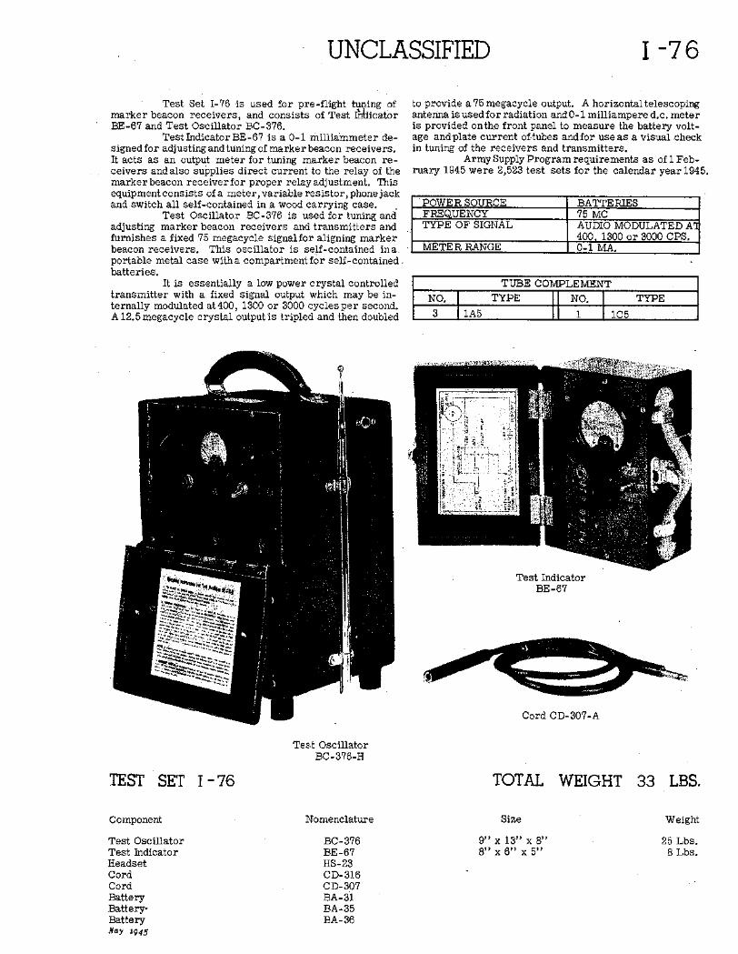
UNCLASSIFIED
Test Set 1-76 is used for pre-flight tu..ing ofmarker beacon receivers, and consists of Test 1 dicatorBE-67 and Test Oscillator BC-376.
Test Indicator BE-67 is a 0-1 milliammeter de-signed for adjusting and tuning of marker beacon receivers.It acts as an output meter for tuning marker beacon re-ceivers and also supplies direct current to the relay of themarker beacon receiver for proper relay adjustment. Thisequipment consists of a meter, variable resistor, phone jackand switch all self-contained in a wood carrying case.
Test Oscillator BC-376 is used for tuning andadjusting marker beacon receivers and transmitters andfurnishes a fixed 75 megacycle signalfor aligning markerbeacon receivers. This oscillator is self-contained inaportable metal case with a compartment for self-containedbatteries.
It is essentially a low power crystal controlledtransmitter with a fixed signal output which may be in-ternally modulated at 400, 1300 or 3000 cycles per second.A 12.5 megacycle crystal output is tripled and then doubled
to provide a 75 megacycle output. A horizontal telescopingantenna is used for radiation and 0-1 milliampere d.c. meteris provided onthe front panel to measure the battery volt-age andplate current of-tubes and for use as a visual .checkin tuning of the receivers and transmitters.
Army Supply Program requirements as of 1 Feb-ruary 1945 were 2,523 test sets for the calendar year 1945.
POWER SOURCE BATTERIESFREQUENCY I 75 MCTYPE OF SIGNAL AUDIO MODULATED A
400. 1300 or 3000 CPS.METER RANGE 0-1 MA.
TUBE COMPLEMENT
NO. TYPE NO. TYPE3 lA5 1 1C5
Test IndicatorBE-67
Cord CD-307-A
Test OscillatorBC-376-H
TEST SET - 76 TOTAL WEIGHT
NomenclatureComponent
Test OscillatorTest IndicatorHeadsetCordCordBatteryBattery-BatteryNay i945
BC-376BE-67HS-23CD-316CD-307BA-31BA-35BA-36
Size
9" x 13" x 8,8" x 6" x-5"
1-76
33 LBS.
Weight
25 Lbs.8 Lbs.

FIF I-100
Test Set I-100 is a compass test set designed totest the operation and performance of Radio Compass SCR-269-G and Radio Compass *AN/ARN-7. It consists of avacuum tube voltmeter with push button selection of volt-age measurements of principal points in loop orientationcircuits and four milliammeters for measuring currentsof the loop motor and indicator circuits.
The voltieter covers 0-2.5, 0-10, 0-50, and 0-250volts a.c. and d.c. The milliammeter ranges are 0-500 ma.d.c. and 0-250, 0-500 and 0 750 ma. ac. The componentsare packed in single cabinet.
Power is obtainedfrom a 115 volt 400 cycle a.c.source.
Army Supply Program requirements as of 1 Feb-
Cabinet, (Cover Removed, Showing Front Panelsof Test Units BC-713-A and BC-714-A)
ruary 1945 were 448 for the calendar year 1945.
POWER SUPPLY 1 115 VOLT 400 CYCLE AC
TUBE COMPLEMENT
NO. TYPE NO. TYPE3 5Z4 2 6B81 6H6 2 20511 6J5 2 6F8G3 150-30 1 6SQ71 6F6 1 6SC7
Front Cover
Cord CD-548-A Cord CD-549-A Cord CD-550-A
Test Prod
Cord CD-551-A
Test Prod
Cord CD-552-A
TEST SET I -100 TOTAL WEIGHT 55 LBS.
Nomenclature
BC-713-ABC-714-ACD-548-ACD-549-ACD-550-ACD-551-ACD-552-A
Size
14" x 13" x 15"13" x 6" x 11"120" long120" long120" long36" long36" long
Component
Test UnitTest UnitCordCordCordPower CordCord
May 1945
Weight
21 Lbs.18 Lbs.
2 Lbs.2 Lbs.2 Lbs.1 Lb.1 Lb.
~LE:.

LASSFI[P
Test Oscillator I-173,specifically designed forpre-flight checking of localizer .receivers, provides radiofrequency oscillation modulated by 90 and 150 cycle sparkgap and radiates a signal for checking the receiver undertest Indicator I-101, a component of the localizer receiverinstallation, indicates operation by right or left movementof the vertical needle.
This oscillator is mounted within a wooden car-rying case which also provides space for the two BatteriesBA-35 required to power it, and a two position toggle switchon the top of the case provides a choice of the 90 or 150cycle modulation.
Army Supply Program requirements as of 22January 1945 were4576for the calendar year 1944 and 253for 1945.
POWER SOURCE ' 2 BATTERIES BA-351. 5 VOLTS
POWER OUTPUT RF CARRIER UNCALIBRATEDAND MODULATED AT 90 OR150 CYCLES
FREQUENCY RANGE 108.3-110.3 MCTYPE OF SIGNAL MODULATED
TEST OSCILLATOR I-173 TOTAL WEIGHT 9 LBS.
Nomenclature
1-173
Size
12" x 4" x 7"
Component
Test Set
Nay 1945
Weight
9 Lbs.
I-173

Ui i BCSLFi
Test Set TS-1/ARR-1 is a test oscillator usedfor the alignment of Radio Receiving Equipment AN/ARR-1.
A type 955 tube in a tuned grid tuned plate cir-cuit provides a 246 mc. signal which is modulated at 710kc. by a circuit employing a second 955 tube. About 70%0modulation is obtained.
This portable test oscillator is housed in a sturdyweather proof metal case provided with a metal carryinghandle. Itcontains a compartmentfor batteries necessaryfor operation. A weather proof canvas duck cover is pro-vided for the protection of the test set.
There were no Army Supply Program require-ments as of 1 February 1945.
TEST SET TS-1/ARR-1
TS- 1/ARR-1
POWER SUPPLY 2 BATTERIES BA-59(45 VOLTS)2 BATTERIES BA-203/U (6 VOLTS)
FREQUENCY _ 246 MCTYPE OF SIGNAL CWMODULATION FREQUENCY 710 KCFREQUENCY ACCURACY 3MOD. ACCURACY i1KCOUTPUT CHARACTER-ISTICS MODULATED CAR-
_TCSRIER UNCALIBRATED
TUBE COMPLEMENTNO. TYPE NO. TYPE
2 955
TOTAL WEIGHT 15 LBS.
Component
Test SetCoverWrench
*Weight less than 1 pound.Nay 2945
Nomenclature
TS-1/ARR-1CW-1/ARR-1
Size
7" x 7" x 11"
Weight
15 Lbs.

UCLASSIFP
TestSet TS-41/CRN-lconsists of a meter 0-1.0milliamperes whichby means of a five position "IndicatorSwitch" is connected to various circuits in Radio Trans-mitter T-2/CRN-1. A copper oxide rectifier bridge cir-cuit is included in Test Set TS-41/CRN-1 to convert a.c.antenna currents to d.c. for measurements and an absorp-tion wavemeter is includedfor measurement of frequency.Finally, a motor and keying switch are included in the testset so that operating tests can be made without using theequivalent circuits in Radio Transmitter T-2/CRN-1.
This set is contained in a metal box which ismounted when in use on the Stand MX-176/CRN-1. Thisstand is designed specifically for holding Radio Trans-mitting Equipment AN/CRN-lwhenbeing tested. The standis collapsible and all components of Test Set TS-41/CRN-1are carried in two wood cases.
Army Supply Program requirements as of 30November were 100 for 1944 and 100 for 1945.
POWER INPUT OBTAINED FROMEQUIPMENT UNDERTEST
FREQUENCY 1400 TO 1750 KC
Dummy AntennaTS-181/CRN-1
TEST SET TS-41/CRN-1
Component Nomenclature
Test Set TS-41/CRN-1Stand MX-176/CRN-1Assembly Tool MX-201/CRN-1Assembly Tool MX-179/CRN-1Code Assembly Tool MX-178/CRN-1Dummy Antenna TS-181/CRN-1Socket WrenchScrew Driver10 Fuses (spares)Case (for accessories CY-148/CRN-1)Case (for metering equipment CY-147/CRN-1)
* Less than one pound.Nay 1945
Test Set TS-41/CRN-1 in case CY-14T7/CRN-1 (1) SpareFuses (2) Spare Calibration Charts.
Test Set TS-41/CRN-1
MX-176/CRN-1
TOTAL WEIGHT 150 LBS.
Size
11" x 10" x 9"30" x 30" x 38"20" x 8"20" x 8"25"
44" x 3"6"
49" x 7" x 34"13" x 14" x 14"
Weight
13 Lbs.27 Lbs.
3 Lbs.3 Lbs.1 Lb.4 Lbs.*
*
80 Lbs.18 Lbs.
TS-41/CRN-1

UN.LASSIFIT ptom'e TS-67/ARN-5
Test Set TS-67/ARN- 5,designed to simulate fre-quency and radiation characteristics of the glide path trans-mitter and localizer associated with the AAF InstrumentApproach System, consists essentially of three radio fre-quency oscillators and one audio oscillator combined witha signal generator unit for aligning and testing localizerand glide path receivers.
In addition, the following assemblies are builtinto this test set: Calibrated audio radio DB control whichprovides fixed differentials between the 90 and 150 cyclemodulating voltages when used simultaneously; monitorcircuit to indicate correct balance when 90 and 150 cyclemodulating voltages are applied together; three calibratedattenuators of the variable mutual inductance type in theoutput circuits of the three RF oscillators. A jack is a-vailable onthis front panel of Test Set TS-67/ARN-5 whichsupplies 150 volts d.c. to the junction box for the purposeof testing early type marker beacon receivers. A markerbeacon indicating lamp is located in the junction box case.No source of rf is furnished for operation of marker beaconreceivers.
The equipment is used for bench testing, adjust-ment and alignment of receivers in Radio Receiving Equip-ment RC-103-A, RC-103-AZ, AN/ARN-5 and AN/ARN-5A.
Two units, Test Set TS-67/ARN-5 and JunctionBox J-81/ARN-5 comprise this equipment and both arecontained in plywood carrying cases.
Army Supply Program requirements as of 31January 1945 were 309 for the calendar year 1945.
POWER INPUT 105-130 VOLTS AC50 OR 60 CYCLES
POWER OUTPUT 1 TO 100,000 MICRO-VOLTS
FREQUENCY 6.9-20.7 MC. 106-114MC. 327-339 MC
TYPE OF SIGNAL RF MODULATEDMODULATION FREQUENCY 1000 CYCLES. 90
CYCLES, 150 CYCLESOR COMBINED 90 AND150 CYCLES
OUTPUT IMPEDANCE 95 OHMSTEMPERATURE RANGE OPERATING -100 TO
+ 600 CNON-OPERATING-55
0C TO + 71
0 C
TUBE COMPLEMENT
NO. TYPE NO. TYPE
1 6X5 2 6SQ71 5Y3 1 6SJ72 OD3-VR-150 2 6SN71 OA3-VR-75 2 9555 6G6 3 6AK5
Cords
Junction BoxJ- 81/ARN-5
Test Set TS-67/ARN-5
TEST SET TS-67/ARN-5 TOTAL WEIGHT 107 LBS.
Component
Test SetIndicatorJunction BoxRadio Control BoxTuning ShuntCordCordCordCordCordCordCordCordCordCord
* Less than one pound..May 1945
Nomenclature
TS-67/ARN-5I-101-()J-81/ARN- 5BC-732-AMX-234/ARN-5CG-59/ARN-5CG-142/ARN-5CX-237/UCX-277/ARN-5CX-278/ARN-5CX-279/ARN-5CX-279/ARN-5CX-280/ARN-5CX-281/ARN-5CD-316-A
Weight
50 Lbs.2 Lbs.
20 Lbs.**
Size
21" x 11" x 15"3" x 3" x 4"16" x 11" x 10"4" x 3" x 3"2" long3 1/2'3 1/2'10'3'3'1'3'3'6'3'
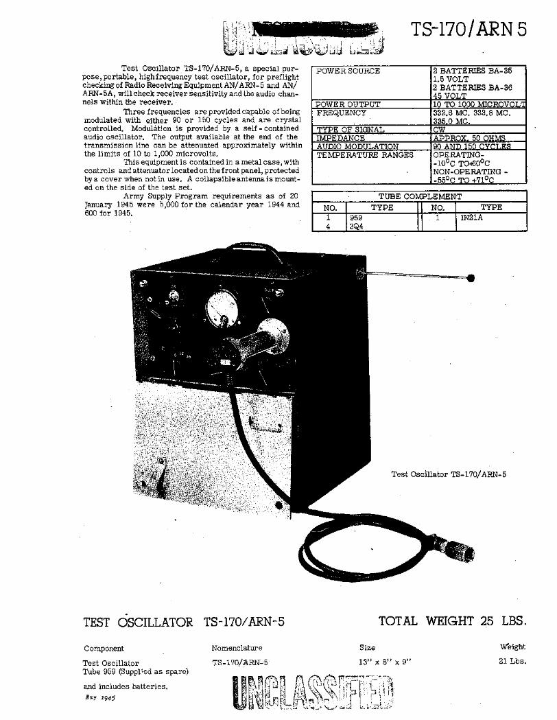
TS-170/ARN 53 -. :
Test Oscillator TS-170/ARN-5, a special pur-pose,portable, highfrequency test oscillator, for preflightchecking of Radio Receiving Equipment AN/ARN- 5 and AN/ARN-5A, will check receiver sensitivity and the audio chan-nels within the receiver.
Three frequencies are provided capable of beingmodulated with either 90 or 150 cycles and are crystalcontrolled. Modulation is provided by a self - containedaudio oscillator. The output available at the end of thetransmission line can be attenuated approximately withinthe limits of 10 to 1,000 microvolts.
This equipment is contained in a metal case, withcontrols and attenuator located on the front panel, protectedby a cover when not in use. A collapsible antenna is mount-ed on the side of the test set.
Army Supply Program requirements as of 20January 1945 were 5,000 for the calendar year 1944 and600 for 1945.
POWER SOURCE 2 BATTERIES BA-351.5 VOLT2 BATTERIES BA-3645 VOLT
POWER OUTPUT 10 TO 1000 MICROVOLFREQUENCY 332.6 MC. 333.8 MC.
335.0 MC.
TYPE OF SIGNAL CWIMPEDANCE APPROX, 50 OHMSAUDIO MODULATION 90 AND 150 CYCLESTEMPERATURE RANGES OPERATING-
-10 0 C TO460°CNON-OPERATING --55 0 C TO +710C
TUBE COMPLEMENTNO. TYPE NO. TYPE1 959 1 IN21A4 3Q4
Test Oscillator TS-170/ARN-5
TEST OSCILLATOR
Component
Test OscillatorTube 959 (Supplied as spare)
and includes batteries.May 1945
TS-.170/ARN-5
Nomenclatur e
TS-170/ARN-5
TOTAL WEIGHT 25
Size
13" x 8" x 9"
N I, ,ri* * IFa - ,.;{;:
LBS.
W'eight
21 Lbs.

COMBINED ARMS RESEARCH LIBRARYFORT LEAVENWORTH KS
3 1695 00539 7039


