Vol. 8, No. 2 / February 2009 / JOURNAL OF OPTICAL NETWORKING 156
Radio-over-fiber transport for thesupport of wireless broadband
services [Invited]
Nathan J. Gomes,1 Maria Morant,2 Arokiaswami Alphones,3 Béatrice Cabon,4
John E. Mitchell,5 Christophe Lethien,6 Mark Csörnyei,7 Andreas Stöhr,8 andStavros Iezekiel9,*
1Department of Electronics, University of Kent, Canterbury, CT2 7NT, United Kingdom2Valencia Nanophotonics Technology Center, Universidad Politécnica de Valencia,
Camino de Vera, s/n, 46022, Valencia, Spain3School of Electrical and Electronic Engineering, Nanyang Technological University,
Singapore 6397984L’Institut de Microélectronique Electromagnétism et Photonique et le Laboratoire
d’Hyperfrequences et de Caractérisation, MINATEC-INPG 3 Parvis Louis Néel, BP 257,38016 Grenoble Cédex, France
5Department of Electronic and Electrical Engineering, University College London,Gower Street, London, WC1E 6BT, United Kingdom
6Institut d’Electronique, de Microélectronique et de Nanotechnologie, UMR 8520,Université des Sciences et Technologies de Lille, Avenue Poincaré, BP 60069, 59652
Villeneuve d’Ascq, France and Research Federation, Institut de Recherche surles Composants Logiciels et Matériels pour l’Information et la Communication Avancée,
FR 3024, Parc Scientifique de La Haute Borne, 50 Avenue Haley,59652 Villeneuve d’Ascq, France
7Department of Broadband Infocommunications and Electromagnetic Theory,Budapest University of Technology and Economics, Goldmann Gy. tér 3,
Budapest, 1111, Hungary8Universität Duisburg-Essen, Optoelektronik, Lotharstrasse 55,
47057 Duisburg, Germany9Department of Electrical and Computer Engineering, University of Cyprus, 75
1. IntroductionRadio over fiber (RoF) has become of increasing interest for the transport of wirelesssignals [1]. Radio over fiber can provide a number of advantages for wireless signaldistribution, such as improved coverage through the use of low-power distributedantennas, transparency and flexibility, trunking efficiency gains, and lower cost ofdeployment [2]. Within the European Network of Excellence ISIS (Infrastructures forbroadband access in wireless/photonics and integration of strengths in Europe) [3],partners have investigated radio-over-fiber transport of various wireless signal types,ranging from those proposed for personal area networks (PANs), through wirelesslocal area networks (LANs), and particularly the ubiquitous WiFi networks, to metro-politan and wide area networks (MANs and WANs). Of course, although novel radio-over-fiber techniques may have been used, or experiments may have been testing theboundaries for the use of low-cost components, where transmission of standard wire-
Vol. 8, No. 2 / February 2009 / JOURNAL OF OPTICAL NETWORKING 157
less signals has been demonstrated, performance is always measured using metricsfor the wireless signals specified in the standards documents. Usually, such perfor-mance is specified in terms of error vector magnitude (EVM) in the multilevel signalconstellation points, but the signal-to-noise ratio (SNR) and bit-error rate (BER) arealso physical layer performance metrics. However, the standards also specify higherlayer protocol operation, and in this paper, studies of such effects in radio-over-fibersystems are also presented. The paper is structured as follows: in Sections 2–4,experiments on the physical layer performance of wireless PANs, LANs, andMANs/WANs, respectively, are presented. In Section 5, the performance limitations ofa high-quality radio-over-fiber link using an external modulator are theoreticallyexposed. In Section 6, the higher-layer protocol effects that have been observed forwireless LAN transport over fiber are discussed, while in Section 7 the demonstrationof a wireless sensor network using radio over fiber is presented. Section 8 describesthe demonstration of 60 GHz RoF systems transmitting broadband data up to12.5 Gbits/s for potential applications in home area networks (HANs). Medium-rangeoutdoor transmission at several Gbits/s has also been achieved. Finally, the work issummarized in Section 9.
2. Radio-over-Fiber Link Experiments: PANsThere is currently great interest in ultrawideband (UWB) communications for futurePANs. The growing interest in UWB is due to its excellent coexistence with otherlicensed and unlicensed wireless services, its low radiated power, its tolerance to mul-tipath fading, and its low probability of interception due to its wide spectrum and lowenergy.
UWB wireless transmission technology targets short-range high-bit-rate communi-cations, potentially exceeding 1 Gbit/s. In this section several experiments usingUWB technology are reported. In the first case, the use of the impulse-radio (IR) tech-nique is used in a scenario that could be seen as a viable solution for the distributionof high-definition audio and video content in fiber-to-the-home (FTTH) networks. Ahigh-bandwidth external optical modulator and standard single-mode fiber (SSMF)are used for IR-UWB transmission over up to 60 km of fiber. In the second experi-ment, a single-mode vertical-cavity surface-emitting laser (VCSEL) is used forIR-UWB transmission in conjunction with frequency upconversion. Although onlyupconversion up to low frequencies is demonstrated, the principle could be applied toupconversion to millimeter-wave frequencies where the radio spectrum of interest forsuch applications exists (such as the 62 to 66 GHz band). The third experimentexamines the transmission of multiband orthogonal frequency division multiplexed(MB-OFDM) UWB signals for indoor fiber installations that are typically based onmultimode fiber (MMF), VCSELs operating at 850 nm, and low-cost receivers.
2.A. IR-UWB over FiberFigure 1 shows the experimental setup to evaluate the IR-UWB signal degradationdue to fiber transmission. IR-UWB monopulses are generated from a 10 GHz Gauss-ian pulse train (full width at half-maximum=2.8 ps) generated by a mode-lockedlaser. The pulse train is gated by a Mach–Zehnder modulator (MZM) with1.25 Gbits/s pseudorandom binary sequence (PRBS) data. The gated optical pulsesare photodetected, monopulse shaped (full width at half-maximum=283 ps) by apulse-shaping filter, and upconverted with a local oscillator (LO) to 6.6 GHz for fibertransmission. The overall −10 dB bandwidth is 3.2 GHz, as shown in Fig. 2(a), andoccupies the band from 5 to 8.2 GHz, following current UWB regulations [4]. UWBsignals must meet stringent equivalent isotropic radiated power (EIRP) limits [5],shown by the dashed line of Fig. 2(a). The electrical signal and the pulse profile trans-mitted are shown in Fig. 2(b).
The average optical power at point (2) in Fig. 1 is adjusted to −2 dBm. The IR-UWBsignal modulates a 20 GHz bandwidth MZM biased at quadrature. Measurementswere carried out back to back and for three FTTH paths of 25, 50, and 60 km reach, asindicated in Fig. 1. Inline amplification is realized by a 23 dB gain erbium-doped fiberamplifier (EDFA) with 4 dB noise figure (Keopsys BT2C-13). The receiver includes anEDFA (Exelite SFA-19) of 4.5 dB noise figure and 19 dBm saturation power. After
Vol. 8, No. 2 / February 2009 / JOURNAL OF OPTICAL NETWORKING 158
transmission, the signal is filtered by a 0.8 nm wide (at −0.5 dBo) optical filter anddetected by a PIN photodiode (with a responsivity of 0.65 A/W and 50 GHz band-width).
Figure 3 shows the BER calculated from the measured Q factor according to BER
Fig. 2. IR-UWB (a) RF spectrum, (b) electrical signal and pulse profile. PSD, power spectraldensity.
Fig. 1. IR-UWB transmission in FTTH demonstration setup.
Fig. 3. IR-UWB BER versus optical power for different RoF SSMF paths.
Vol. 8, No. 2 / February 2009 / JOURNAL OF OPTICAL NETWORKING 159
=0.5�erfc�Q /�2�. Transmission up to 50 km of SSMF is achieved with a BER of 10−9.These experimental results therefore demonstrate the feasibility of radio-over-fiberdistribution of 1.25 Gbits/s IR-UWB.
2.B. IR-UWB over SSMF and UpconversionHere, IR-UWB pulses are upconverted for transmission over 1 m of SSMF with adirectly modulated laser diode. A low-cost, single-mode VCSEL at 1550 nm having arelaxation frequency of 8.5 GHz was used to demonstrate the feasibility of upconvert-ing a monocycle while retaining a high resemblance. The results are essentially thesame for lengths of SSMF up to 100 m.
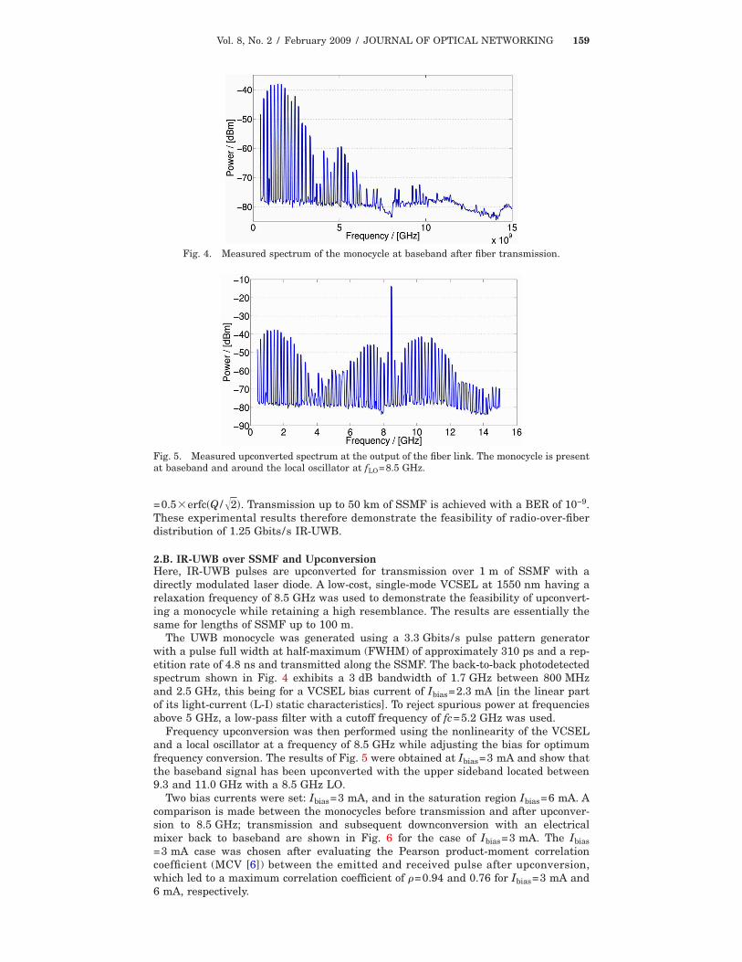
The UWB monocycle was generated using a 3.3 Gbits/s pulse pattern generatorwith a pulse full width at half-maximum (FWHM) of approximately 310 ps and a rep-etition rate of 4.8 ns and transmitted along the SSMF. The back-to-back photodetectedspectrum shown in Fig. 4 exhibits a 3 dB bandwidth of 1.7 GHz between 800 MHzand 2.5 GHz, this being for a VCSEL bias current of Ibias=2.3 mA [in the linear partof its light-current (L-I) static characteristics]. To reject spurious power at frequenciesabove 5 GHz, a low-pass filter with a cutoff frequency of fc=5.2 GHz was used.
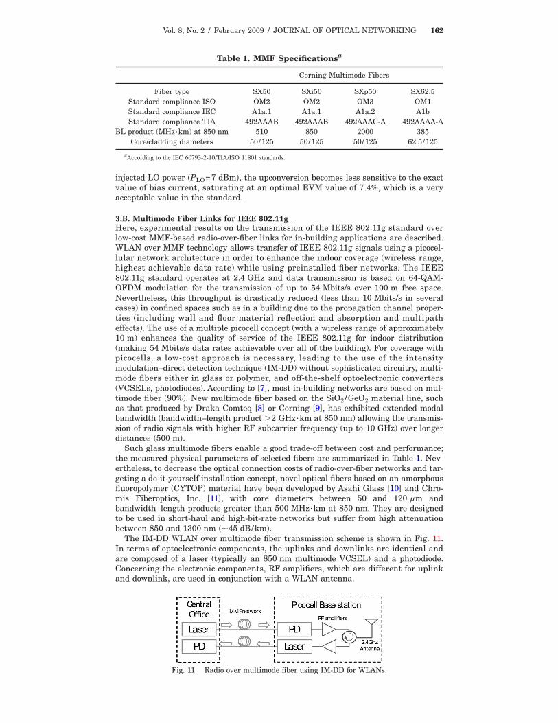
Frequency upconversion was then performed using the nonlinearity of the VCSELand a local oscillator at a frequency of 8.5 GHz while adjusting the bias for optimumfrequency conversion. The results of Fig. 5 were obtained at Ibias=3 mA and show thatthe baseband signal has been upconverted with the upper sideband located between9.3 and 11.0 GHz with a 8.5 GHz LO.
Two bias currents were set: Ibias=3 mA, and in the saturation region Ibias=6 mA. Acomparison is made between the monocycles before transmission and after upconver-sion to 8.5 GHz; transmission and subsequent downconversion with an electricalmixer back to baseband are shown in Fig. 6 for the case of Ibias=3 mA. The Ibias=3 mA case was chosen after evaluating the Pearson product-moment correlationcoefficient (MCV [6]) between the emitted and received pulse after upconversion,which led to a maximum correlation coefficient of �=0.94 and 0.76 for Ibias=3 mA and6 mA, respectively.
Fig. 4. Measured spectrum of the monocycle at baseband after fiber transmission.
Fig. 5. Measured upconverted spectrum at the output of the fiber link. The monocycle is presentat baseband and around the local oscillator at fLO=8.5 GHz.
Vol. 8, No. 2 / February 2009 / JOURNAL OF OPTICAL NETWORKING 160
2.C. MB-UWB over FiberFigure 7 shows the experimental setup used to evaluate the performance of the trans-mission of standard MB-OFDM UWB, as defined in international standard ECMA-368 [4], over multimode fiber.
Figure 8 shows the measured EVM when UWB-OFDM signals are transmittedthrough 100, 200, 300, and 400 m lengths of multimode fiber (MMF). The quality ofthe UWB signal degrades quickly due to the modal dispersion at higher frequencies.Nevertheless, EVM results after transmission through 400 m of fiber satisfy theECMA-368 standard requirements of 18.84% EVM [4].
3. Radio-over-Fiber Link Experiments: Wireless LANsIn this section, the transmission of the now ubiquitous IEEE wireless LAN signalsover fiber is investigated. Two contrasting experiments are presented: in the first,
Fig. 7. Experimental setup for performance analysis of MB-OFDM UWB on fiber.
Fig. 8. MB-OFDM UWB EVM results for different MMF lengths.
Fig. 6. Original baseband monocycle and after upconversion at 8.5 GHz, Ibias=3 mA.
Vol. 8, No. 2 / February 2009 / JOURNAL OF OPTICAL NETWORKING 161
upconversion following that presented for IR-UWB in the previous section is applied,again with a view to providing a proof of principle for future millimeter-wave systems;in the second, low-cost VCSEL MMF links (including both glass and polymer fibertypes) are investigated, primarily with a view to in-building distribution systems.
3.A. 802.11a and UpconversionFor similar reasons as for the upconversion of the IR-UWB signals, here the transmis-sion and upconversion to 5.1 GHz of a wireless LAN (WLAN) IEEE 802.11a signalover 2 m of SSMF is investigated. The radio-over-fiber link shown in Fig. 9 transportsan analog radio signal to a remote antenna, where the detected electrical signal afterthe RF amplifier can be transmitted without further processing. However, frequencyupconversion is necessary in future WiMax systems (for example) since they canexploit the 2 to 66 GHz band. As in Section 2, the nonlinearity of a low-cost 1550 nmsingle-mode VCSEL diode is exploited to perform upconversion, thus overcoming itsintrinsic bandwidth limitation. A LO at fLO=2 GHz was used for frequency upconver-sion; together with the WLAN data, it directly modulates the VCSEL.
The quality of the signal after the upconversion process was evaluated by measure-ments of the root-mean-square (rms) EVM of the constellation points. The commercialsoftware package Advanced Design System was used to generate the complex wave-forms of a WLAN 64-QAM (quadrature amplitude modulated) IEEE 802.11a OFDMsignal at a bit rate of 54 Mbits/s, occupying a band of 20 MHz. The waveforms weresubsequently uploaded to an Agilent vector signal generator ESG E4438C, which per-forms modulation of a carrier frequency of fRF=1.1 GHz. The EVM was evaluated atthe output of the system by vector signal analyzer (VSA) software running on an Agi-lent digital sampling oscilloscope (DSO).
The desired mixing product is fRF+2fLO and is at 5.1 GHz after the optical-microwave mixing process, where the RF signal is the WLAN signal. As in Section 2,the bias current of the VCSEL was set to Ibias�3 mA to optimize mixing. The goalwas to minimize the EVM while maximizing the upconverted power to the desiredintermodulation frequency. To achieve this, optimization of the values of the bias cur-rent Ibias, the injected RF power PRF of the WLAN signal, and the local oscillatorpower PLO was required.
Figure 10 shows the strong influence of PLO on the measured EVM. For a high
Fig. 9. Typical implementation of a radio-over-fiber system.
Fig. 10. Measured EVM after upconversion to fRF+2fLO=5.1 GHz as a function of the power ratioP /P between the RF signal and the local oscillator.
RF LO
Vol. 8, No. 2 / February 2009 / JOURNAL OF OPTICAL NETWORKING 162
injected LO power �PLO=7 dBm�, the upconversion becomes less sensitive to the exactvalue of bias current, saturating at an optimal EVM value of 7.4%, which is a veryacceptable value in the standard.
3.B. Multimode Fiber Links for IEEE 802.11gHere, experimental results on the transmission of the IEEE 802.11g standard overlow-cost MMF-based radio-over-fiber links for in-building applications are described.WLAN over MMF technology allows transfer of IEEE 802.11g signals using a picocel-lular network architecture in order to enhance the indoor coverage (wireless range,highest achievable data rate) while using preinstalled fiber networks. The IEEE802.11g standard operates at 2.4 GHz and data transmission is based on 64-QAM-OFDM modulation for the transmission of up to 54 Mbits/s over 100 m free space.Nevertheless, this throughput is drastically reduced (less than 10 Mbits/s in severalcases) in confined spaces such as in a building due to the propagation channel proper-ties (including wall and floor material reflection and absorption and multipatheffects). The use of a multiple picocell concept (with a wireless range of approximately10 m) enhances the quality of service of the IEEE 802.11g for indoor distribution(making 54 Mbits/s data rates achievable over all of the building). For coverage withpicocells, a low-cost approach is necessary, leading to the use of the intensitymodulation–direct detection technique (IM-DD) without sophisticated circuitry, multi-mode fibers either in glass or polymer, and off-the-shelf optoelectronic converters(VCSELs, photodiodes). According to [7], most in-building networks are based on mul-timode fiber (90%). New multimode fiber based on the SiO2/GeO2 material line, suchas that produced by Draka Comteq [8] or Corning [9], has exhibited extended modalbandwidth (bandwidth–length product �2 GHz·km at 850 nm) allowing the transmis-sion of radio signals with higher RF subcarrier frequency (up to 10 GHz) over longerdistances �500 m�.
Such glass multimode fibers enable a good trade-off between cost and performance;the measured physical parameters of selected fibers are summarized in Table 1. Nev-ertheless, to decrease the optical connection costs of radio-over-fiber networks and tar-geting a do-it-yourself installation concept, novel optical fibers based on an amorphousfluoropolymer (CYTOP) material have been developed by Asahi Glass [10] and Chro-mis Fiberoptics, Inc. [11], with core diameters between 50 and 120 �m andbandwidth–length products greater than 500 MHz·km at 850 nm. They are designedto be used in short-haul and high-bit-rate networks but suffer from high attenuationbetween 850 and 1300 nm ��45 dB/km�.
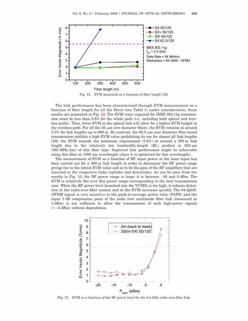
The IM-DD WLAN over multimode fiber transmission scheme is shown in Fig. 11.In terms of optoelectronic components, the uplinks and downlinks are identical andare composed of a laser (typically an 850 nm multimode VCSEL) and a photodiode.Concerning the electronic components, RF amplifiers, which are different for uplinkand downlink, are used in conjunction with a WLAN antenna.
Table 1. MMF Specificationsa
Corning Multimode Fibers
Fiber type SX50 SXi50 SXp50 SX62.5Standard compliance ISO OM2 OM2 OM3 OM1Standard compliance IEC A1a.1 A1a.1 A1a.2 A1bStandard compliance TIA 492AAAB 492AAAB 492AAAC-A 492AAAA-A
aAccording to the IEC 60793-2-10/TIA/ISO 11801 standards.
Fig. 11. Radio over multimode fiber using IM-DD for WLANs.
Vol. 8, No. 2 / February 2009 / JOURNAL OF OPTICAL NETWORKING 163
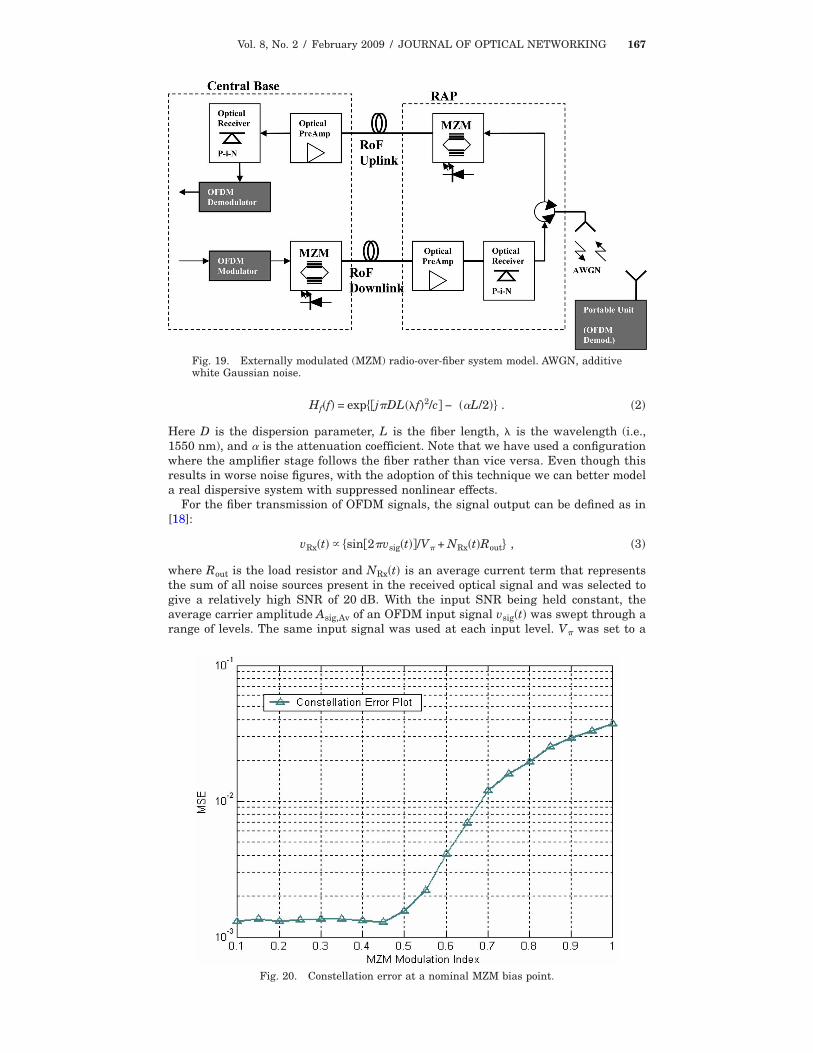
The link performance has been characterized through EVM measurement as afunction of fiber length for all the fibers (see Table 1) under consideration; theseresults are presented in Fig. 12. The EVM (rms) required for IEEE 802.11g transmis-sion must be less than 5.6% for the whole path (i.e., including both optical and wire-less paths). Thus, lower EVM in the optical link will allow for a higher EVM budget inthe wireless path. For all the 50 �m core diameter fibers, the EVM remains at around2.5% for link lengths up to 600 m. By contrast, the 62.5 �m core diameter fiber-basedtransmission exhibits a high EVM value prohibiting its use for almost all link lengths[10]; the EVM exceeds the minimum requirement (5.6%) at around a 200 m linklength due to the relatively low bandwidth–length (BL) product at 850 nm(385 MHz·km) of this fiber type. Improved link performance might be achievableusing this fiber at 1300 nm wavelength (since it is optimized for this wavelength).
The measurement of EVM as a function of RF input power at the laser input hasbeen carried out for a 300 m link length in order to determine the RF power rangegiving rise to the lowest EVM value and so to fix the gain of the RF amplifiers that areinserted in the respective links (uplinks and downlinks). As can be seen from theresults in Fig. 13, the RF power range is large; it is between −20 and 0 dBm. TheEVM is relatively flat over this power range corresponding to the best transmissioncase. When the RF power level launched into the VCSEL is too high, it induces distor-tion in the radio-over-fiber system and so the EVM increases quickly. The 64-QAM-OFDM signal is very sensitive to the peak-to-average power ratio (PAPR) and theinput 1 dB compression point of the radio over multimode fiber link (measured as3 dBm) is not sufficient to allow the transmission of such high-power signals��−2 dBm� without degradation.
Fig. 12. EVM measured as a function of fiber length [12].
Fig. 13. EVM as a function of the RF power level for the 2.4 GHz radio-over-fiber link.
Vol. 8, No. 2 / February 2009 / JOURNAL OF OPTICAL NETWORKING 164
3.C. General Discussion on Multiple System Configurations and Remote PoweringRadio-over-fiber distribution of WLAN signals allows flexible system architectures inwhich the signals from co-located WiFi access points can be transported to and frommultiple remote access units (RAUs) to improve coverage or can be combined andtransported to individual RAUs to improve capacity in traffic hot-spot areas [13]. Inaddition, the signals of other standard systems such as PANs (as discussed in Section2) and WiMAX and mobile communications systems (as discussed in Section 4) can betransported to the same RAUs, permitting cost sharing between the systems. Whenmultiple systems are to operate over the same radio-over-fiber links, two generaloptions are possible in the design of the RAUs [13]. In the first, the signals use com-mon amplifier chains in the RAU: this may minimize cost but does not allow for opti-mization of the power and noise budget according to each system’s requirements, andthe requirements for a Global System for Mobile Communication (GSM) type systemusing Gaussian minimum shift keying modulation, which is very tolerant to systemnonlinearities, are very different from those of an OFDM-type system such as IEEE802.11a/g, which is very susceptible to nonlinear effects (as shown in the previous sub-section). Cost reduction might also be lessened by the fact that wider bandwidthamplifiers (covering all required systems) and higher performance (e.g., in terms ofthird-order intercept points) might be required. The alternative is to separate theamplifier chains for the different systems as far as possible. The intermodulationproducts can also be removed by RF filtering in such a scheme. The problem thenbecomes the increased component count, and, most likely, increased cost. Power con-sumption will generally also increase with the increased component count. Interestingwork has been carried out on powering low-cost RAUs optically, using power-over-fiberlinks [14]. This is eminently suitable for the simpler, low-component-count RAUapproach. Finally, as has been discussed in [13], it may not be necessary to optimizefor equal wireless distances for all systems. Whereas WLAN signals may be sent toand from all (or nearly all) RAUs, mobile communication system signals may be sentto and from fewer RAUs taking advantage of the generally greater wireless distancespossible with similar transmit and receive power levels and of the lesser demand onthese systems for high-bandwidth services.
4. Radio-over-Fiber Link Experiments: Wireless MANs and 3GA key enabler for supporting very high data rates and many users in advanced net-works is the reduction in cell size. This is apparent for 802.16 WiMAX and third-generation (3G) mobile communications, with picocellular system design being pro-posed. Radio-over-fiber distribution has been proposed for such systems, and forin-building distribution, multimode fiber is considered attractive for moderate dis-tance transmission up to some hundreds of meters. In this section, we examine radio-
Fig. 14. Measurement setup for WiMAX over MMF.
Fig. 15. (a) WiMAX EVM measurements results and (b) measured conformance with spectralmask.
Vol. 8, No. 2 / February 2009 / JOURNAL OF OPTICAL NETWORKING 165
over-multimode-fiber experiments for WiMAX and 3G systems that use low-cost,short-wavelength �850 nm� VCSELs and multimode fiber.
4.A. WiMAX over FiberThe experimental setup for the WiMAX work is shown in Fig. 14. Measurementsusing a 3.5 MHz 64-QAM 3/4 WiMAX signal at the 3.5 GHz operating band over dif-ferent fiber lengths up to 400 m are shown in Fig. 15. The signal quality (EVM) mea-surements at the antenna in Fig. 15(a) show that the EVM remains below the limit of3.1% imposed by the standard for the corresponding 64-QAM modulation. Figure15(b) shows that the received signal in the experiment complies with the standardspectral mask, necessary to avoid interference in adjacent channels.
4.B. Third Generation Partnership Project (3GPP) and Adjacent Channel LeakageRatioTestingTesting of the EVM performance of 3G systems transported over multimode fiber linkshas also been carried out. In fact, in the experimental setup shown in Fig. 16 [13],multiple systems were transported, although here we concentrate on the resultsobtained for the 3G system Universal Mobile Telecommunications System (UMTS).The EVM results measured at the antenna port of the downlink are presented in Fig.17; similar results would be measured in the uplink. As the EVM requirement is
Fig. 16. Experimental setup for multisystem transport over a VCSEL multimode fiber link [13].
Fig. 17. EVM measurements for downlink UMTS radio-over-fiber transmission in thesystem of Fig. 16 as a function of central unit VCSEL RF drive power. Note: all othersystems are present [13].
Vol. 8, No. 2 / February 2009 / JOURNAL OF OPTICAL NETWORKING 166
12.5%, the measurements demonstrate conformance over the whole range and suggestan operational dynamic range of much greater than 35 dB. However, the measure-ments of the adjacent channel leakage ratio (ACLR) shown in Fig. 18 demonstrate afurther limitation often neglected in system experiments. The UMTS ACLR require-ments are 50 dB at 10 MHz offset and 45 dB at 5 MHz offset. In the measurements ofFig. 18, the system noise floor is measured until the onset of significant VCSEL non-linearity, which results in the channel leakage. The emitted noise requirement isbeing met, but in the region at higher power levels where the curves start decreasing,the ACLR is dominant. In the system measured, therefore, the drive power to theVCSEL is limited to less than 0 dBm because of the ACLR requirement (whereas theEVM measurement suggested it could exceed 5 dBm).
5. Externally Modulated Link Modeling for OFDM Signals over FiberRoF systems employ a centralized architecture wherein, by delivering the radio sig-nals directly, the optical fiber link avoids the necessity to generate high-frequencyradio carriers at the antenna site. Since antenna sites are usually remote from easyaccess, there is much to gain from such an arrangement [15]. A key aspect of RoF sys-tem design is the assessment of modulation formats and OFDM in particular. Earlysimulation studies focused on examining the feasibility of OFDM in multimode RoFsystems for directly modulated [16] and externally modulated links [17].
In this work, the behavior of an OFDM signal in a radio over fiber for WLAN envi-ronment has been studied. Figure 19 depicts the RoF system being simulated. A MZMwas employed to modulate an optical signal. The MZM transfer function can be repre-sented as given in Eq. (1):
where v1�t� and v2�t� represent the time-varying electrical signals applied to each elec-trode of the MZM. V� is the switching voltage of the MZM and is a constant for a par-ticular device. � is related to the extinction ratio r measured at the output of the MZMas ��r−1� / ��r+1� [18].
The simulation model is designed with the considerations of a RoF system used todistribute 802.11a WLAN signals [19]. The signal behavior after the remote accesspoint (RAP) has been rigorously modeled, including the channel noise. The perfor-mance evaluation simulations were performed on the downlink (i.e., base station toportable device) channel with the assumption that the uplink path is essentially amirror image of the downlink. The OFDM modulator and demodulator [20] weresimulated in MATLAB in accordance with the 802.11a physical layer specifications.
The effect of attenuation and dispersion in the fiber is applied on the signal in theFourier domain using the transfer function of the fiber [15]:
Fig. 18. ACLR measurement for UMTS for the setup of Fig. 16 with all other systemspresent. The rising part of the curves is within conformance (although they are belowthe 50 and 45 dB requirements) as noise rather than signal leakage is measured in thisregion [13].
Vol. 8, No. 2 / February 2009 / JOURNAL OF OPTICAL NETWORKING 167
Hf�f� = exp��j�DL��f�2/c� − ��L/2� . �2�
Here D is the dispersion parameter, L is the fiber length, � is the wavelength (i.e.,1550 nm), and is the attenuation coefficient. Note that we have used a configurationwhere the amplifier stage follows the fiber rather than vice versa. Even though thisresults in worse noise figures, with the adoption of this technique we can better modela real dispersive system with suppressed nonlinear effects.
For the fiber transmission of OFDM signals, the signal output can be defined as in[18]:
vRx�t� �sin�2�vsig�t��/V� + NRx�t�Rout , �3�
where Rout is the load resistor and NRx�t� is an average current term that representsthe sum of all noise sources present in the received optical signal and was selected togive a relatively high SNR of 20 dB. With the input SNR being held constant, theaverage carrier amplitude Asig,Av of an OFDM input signal vsig�t� was swept through arange of levels. The same input signal was used at each input level. V� was set to a
Fig. 20. Constellation error at a nominal MZM bias point.
Vol. 8, No. 2 / February 2009 / JOURNAL OF OPTICAL NETWORKING 168
typical value of 4 V. The MZM is biased at VBias,Nom=V� /2 as in virtually every appli-cation in which the device is used. This is the point on the MZM transfer function thatis most linear and provides the greatest input/output power efficiency. In Fig. 20, themean-squared constellation error MSEConst is plotted as a function of the modulationindex �MZM:
�MZM = Asig,Av/0.5V�. �4�
The curve remains essentially constant at a level slightly greater than 10−3 for lowvalues of �MZM. Constellation degradation increases near �MZM=0.45 when theMSEConst increases rapidly. At this point the signal degradation caused by noise is ata minimum, so this is the optimal operating point for the link.
Figure 21 shows the average optical intensity at the output of the MZM for a given�MZM. The result also shows the input signal amplitude as a function of the modula-tion index. From the observations we see that the received SNR would be significantlyincreased with an increase in the modulation index above the optimal operating point.In Fig. 22 the simulation results depict the dependence of the BER on the fiber length.Simulation results are extracted without the use of any error correction as well as byusing forward error correction (FEC) with a constraint length of 7 as recommended by802.11a.
Fig. 21. Signal amplitude and output intensity (nominal bias point).
Fig. 22. BER dependence on fiber length.
Vol. 8, No. 2 / February 2009 / JOURNAL OF OPTICAL NETWORKING 169
For the simulated RoF system model, we can see that an input power of −14 to−16 dBm would be ideal to achieve a BER of 10−3 to 10−4 for a fiber length of less than1 km, without the use of FEC. We can also expect little performance degradation (withrespect to transmitted power) for the longer fiber lengths of 2 and 4 km. While usingFEC, a performance gain of approximately 4 dBm is achieved for fiber lengths of 1and 2 km.
The receiver simulation results shown in Fig. 23 (compared with Fig. 22) show apower loss of 3 to 4 dBm for transmission over a 1 km length of SSMF. From thesimulations, it is evident that the receiver sensitivity can be further improved withthe use of the FEC techniques of IEEE 802.11a. A receiver power level of −21 to−19 dBm is required for achieving the target BER performance from the system withthe use of FEC.
6. Higher-Layer Protocol IssuesAlthough many experiments at the physical layer (such as those described in Sections2–4) have demonstrated significant fiber transmission distances, other effects, such asthose on the media access control (MAC) protocol, can degrade performance. The pro-tocols defined in a radio standard, for example, the IEEE 802.11 standard imple-mented in WiFi, at layer 2 or above, such as the Internet protocol (IP), the transmis-sion control protocol (TCP), or the user datagram protocol (UDP), will all interact todetermine the total transmission capacity of any radio-over-fiber system.
6.A. Impact of the 802.11 MACConsidering first the impact of the IEEE 802.11 MAC, it is straightforward to showthat the fiber length that can be introduced into the system is limited by the acknowl-edge (ACK) and clear-to-send (CTS) time-out values implemented by the access point.These time outs, set with the assumption of only a relatively short wireless channel,will expire and result in lost packets if exceeded by the time delay introduced by theaddition of optical fiber.
Experimental and simulation-based investigations have been performed to showthe expected ranges given minimum and typical time-out values [21,22]. Figure 24shows results when the distributed coordination function (DCF) basic access mode isused in the downlink, with the case for the uplink being almost identical when only a
Fig. 23. Receiver performance with FEC.
Vol. 8, No. 2 / February 2009 / JOURNAL OF OPTICAL NETWORKING 170
single station is considered. The experimental setup follows that shown in [23]. Figure25 shows the same results when the DCF request-to-send/clear-to-send (RTS/CTS)access mechanism is used.
First, it is noted that the throughput is always lower than the data rate (in theexample of 802.11b this is 11 Mbits/s) due to the control overhead. The impact of thisis exacerbated by all control frames being transmitted at 1 Mbit/s. With the RTS/CTS
Fig. 24. Variation of throughput with fiber length using basic access.
Fig. 25. Variation of throughput with fiber length using RTS/CTS.
Vol. 8, No. 2 / February 2009 / JOURNAL OF OPTICAL NETWORKING 171
access mechanism there is a higher overhead than with the basic access mechanismdue to the extra transmission required. As the fiber length is increased, the through-put of the system steadily decreases due to the increased waiting time between packettransfers caused by the fiber propagation. However, there comes a point when thethroughput rapidly decreases when the time-out value is exceeded and all packets areassumed to be lost. Channel errors, which cause lost frames as specified by the frameerror rates (FERs) shown in Figs. 24 and 25, also affect the performance of the MACprotocol since they increase the number of retransmissions at the MAC level. Experi-mental measurements show that, due to this, 5%–7% of packets are transmitted at5.5 Mbits/s.
It has been shown that an increase in the number of contending stations will resultin the system’s throughput not reaching the maximum theoretical throughput due tothe increase in the number of collisions from simultaneous transmissions [24]. It isknown that in a highly contended environment RTS/CTS provides better performanceand so is considered here (other schemes can be found in [22]). Figure 26 shows therelative performance of both the basic and RTS/CTS mechanisms for two station andbidirectional transmission. The transmission rate of control frames for the resultsshown is 1 Mbit/s. We see that the rate of decline is slightly higher for the basic accessmethod, and that, due to a difference in the time-out values for control and data pack-ets, its transmission distance is greater. It is shown that the available capacity isshared between the two stations in an equitable manner.
The new burst-mode transmission mechanisms in the IEEE 802.11e standardrequire fewer (or even no) acknowledgments. This streamlining of the acknowledg-ment procedure has been shown to dramatically improve performance when used inradio-over-fiber systems [25], although care must be taken to guard against undulyhigh frame loss due to noise and errors and collisions when the numbers of acknowl-edgments are reduced.
6.B. Impact of TCP and UDPSince the 802.11 MAC provides for retransmissions, retransmissions at the TCP layermay not be necessary. Thus, we consider UDP as an alternative transport protocol toTCP. Figure 27 shows simulation results for throughput comparing TCP and UDPwith the maximum achievable throughput when basic access is used in the downlink.
Fig. 26. Variation of throughput with fiber length for TCP transmission (control datarate 1 Mbit/s)
Vol. 8, No. 2 / February 2009 / JOURNAL OF OPTICAL NETWORKING 172
It can be seen that the UDP throughput is comparable with that of the MAC itself,whereas the TCP throughput is lower due to the TCP ACK procedure overhead. Theslightly higher slope for the TCP case shows that the fiber length adversely affectsTCP transmission due to the extra time needed for the TCP ACK procedure. Whenusing the basic access method in a TCP downlink the reduction in throughputincreases from 10% when no fiber is used to 15% for 13.1 km of fiber.
7. Demonstration of the Operation of a Complete Sensor NetworkWireless indoor communication systems applying an optical backbone provide an eco-nomic and flexible approach for sensor area networks in buildings. In this approachthe IEEE-802.15.4-based low-rate wireless communication can be extended by opticalcables. The performance of the 802.15.4 ZigBee system is enhanced by the advantagesof the combined optical-wireless network solution, such as robustness against electro-magnetic interference and flexible subnetwork connections. This method allows for asimple and low-cost indoor communication system [26].
Wireless sensor networks are used in different situations. An important area of con-cern is home and building monitoring, particularly for fire control and other securityaspects. These networks are far more flexible both in installation and in the runningoperation mode than conventional wired networks. Due to the low data rate�20–200 kbits/s� transmission, defined by the physical and media access layer of theIEEE 802.15.4 standard model, extremely low power consumption (and hence low-costoperation) is feasible. In addition, the low power consumption is supported by the net-work layer of the transmission, which is defined by the ZigBee Alliance. Due to thenetwork layer operation, the temporarily unused nodes can go over in different dozeand sleeping modes, and so the wireless nodes can operate essentially in wirelessmode using batteries. This kind of network structure makes the reorganization of thenetwork easy and allows dynamic variation of network structure and functionmatched to the changing application requirements.
A further advantage of such wireless sensor networks is their self-healing charac-teristic, which warrants a very simple installation and a highly flexible operation.
In the case of large buildings such as airports and conference centers the coopera-tion of locally separated networks has special importance. The apparent solution is touse low-cost short-range optical connections, which gives secure information transmis-
Fig. 27. UDP, TCP, and the MAC maximum achievable throughput simulation results.
Vol. 8, No. 2 / February 2009 / JOURNAL OF OPTICAL NETWORKING 173
sion possibility regarding the electromagnetic interference. According to this networkscheme, some of the wireless routers of the separated subnetworks are connected viafibers.
In addition, ZigBee has limitations that are rooted in the fundamental principlesthat created it. One such limitation is the maximum depth of a ZigBee network, as inthe maximum number of devices that can join to each other forming a chain, with theZigBee Coordinator (ZC) at the top. In a ZigBee network, that number is 15; thus themaximum possible diameter of a network is 30, with the ZigBee Coordinator in thecenter. This limitation is particularly related to the maximum possible operationalarea of the network. If greater area coverage is necessary, optical links between Zig-Bee routers present an obvious solution.
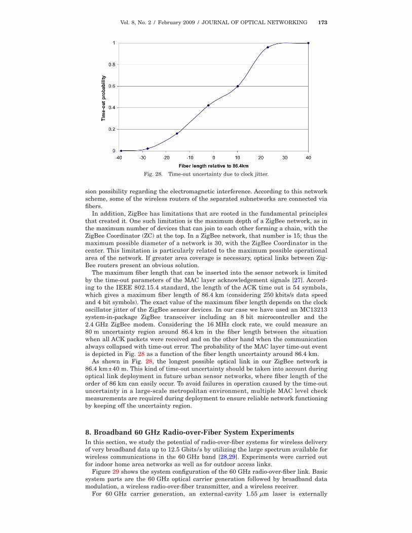
The maximum fiber length that can be inserted into the sensor network is limitedby the time-out parameters of the MAC layer acknowledgement signals [27]. Accord-ing to the IEEE 802.15.4 standard, the length of the ACK time out is 54 symbols,which gives a maximum fiber length of 86.4 km (considering 250 kbits/s data speedand 4 bit symbols). The exact value of the maximum fiber length depends on the clockoscillator jitter of the ZigBee sensor devices. In our case we have used an MC13213system-in-package ZigBee transceiver including an 8 bit microcontroller and the2.4 GHz ZigBee modem. Considering the 16 MHz clock rate, we could measure an80 m uncertainty region around 86.4 km in the fiber length between the situationwhen all ACK packets were received and on the other hand when the communicationalways collapsed with time-out error. The probability of the MAC layer time-out eventis depicted in Fig. 28 as a function of the fiber length uncertainty around 86.4 km.
As shown in Fig. 28, the longest possible optical link in our ZigBee network is86.4 km±40 m. This kind of time-out uncertainty should be taken into account duringoptical link deployment in future urban sensor networks, where fiber length of theorder of 86 km can easily occur. To avoid failures in operation caused by the time-outuncertainty in a large-scale metropolitan environment, multiple MAC level checkmeasurements are required during deployment to ensure reliable network functioningby keeping off the uncertainty region.
8. Broadband 60 GHz Radio-over-Fiber System ExperimentsIn this section, we study the potential of radio-over-fiber systems for wireless deliveryof very broadband data up to 12.5 Gbits/s by utilizing the large spectrum available forwireless communications in the 60 GHz band [28,29]. Experiments were carried outfor indoor home area networks as well as for outdoor access links.
Figure 29 shows the system configuration of the 60 GHz radio-over-fiber link. Basicsystem parts are the 60 GHz optical carrier generation followed by broadband datamodulation, a wireless radio-over-fiber transmitter, and a wireless receiver.
For 60 GHz carrier generation, an external-cavity 1.55 �m laser is externally
Fig. 28. Time-out uncertainty due to clock jitter.
Vol. 8, No. 2 / February 2009 / JOURNAL OF OPTICAL NETWORKING 174
modulated using a Mach–Zehnder modulator (MZM-1) at a frequency of fLO/2=30 GHz. Bias is set to V� for generating an optical double-sideband–suppressed-carrier (DSB-SC) signal. The optical millimeter-wave signal is subsequently modu-lated by non-return-to-zero on–off-keying data (NRZ-OOK, 231−1) in a second modu-lator (MZM-2). After fiber-optic transmission to the wireless transmitter via SSMF,the signal is detected by a 70 GHz photodetector. Before wireless transmission with a20 dBi gain horn antenna, an amplifier is implemented to boost the RF power level upto approximately +11 dBm so as to extend the wireless path length. The signal isreceived by an identical 20 dBi horn antenna and amplified by a low-noise amplifier(LNA). BER analysis is performed after direct downconversion of the 60 GHz signal tobaseband.
For studying the applicability of the constructed system for HANs, short-rangeindoor tests were carried out, in which the wireless signal was transmitted within alaboratory environment allowing a maximum wireless path length of approximately11 m. From BER measurements (Fig. 30) we can demonstrate error-free broadband
Fig. 29. Schematic of the 60 GHz radio-over-fiber setup.
Fig. 30. BERs and 10 Gbits/s eye diagram after 2.5 m wireless transmission.
Vol. 8, No. 2 / February 2009 / JOURNAL OF OPTICAL NETWORKING 175
wireless transmission up to 12.5 Gbits/s. No error floor was observed in the BER mea-surements down to BERs of �10−11. For a BER of 10−9 (231−1, NRZ) and 2.5 m wire-less indoor transmission the measured receiver sensitivity for 10 Gbits/s is−47.6 dBm. We also investigated the maximum wireless path length the system couldaccommodate at a given data rate to demonstrate the capacity of the constructed sys-tem link for short-range indoor communication. Here, we achieved 10 Gbits/s broad-band wireless transmission over distances up to approximately 10 m.
For studying access link scenarios, medium-range outdoor experiments were car-ried out at a height of approximately 120 cm and surrounded by buildings, limitingthe maximum wireless path length to 40 m.
Various experiments were carried out for data rates of 7.5 Gbits/s, 10.3125 Gbits/s[gross rate for 64/66 coded 10 gigabit Ethernet (10 GbE)], and 12.5 Gbits/s (gross ratefor 8/10 coded 10 GbE). Figure 31 shows BER characteristics after 20 and 40 m wire-less transmission and eye diagrams after 40 m wireless transmission. From theresults, a sensitivity of −46 dBm for error-free �BER�10−9� 10.3125 Gbits/s transmis-sion is observed. The system even achieved 12.5 Gbits/s wireless transmission over 20m. The sensitivity for 10.3125 Gbits/s operation after a 40 m wireless path length isslightly better than for 20 m, which is attributed to reflections from buildings. Weexpect a general improvement in receiver sensitivity due to reduced multipath propa-gation, provided the transmitter and receiver are located at a better position, forexample, on the roof between two buildings.
Based upon the outdoor experiments, we further studied the potential of extendingthe wireless path length to the kilometer range by using high-gain antennas such as50 dBi Cassegrain antennas. Although higher millimeter-wave frequencies in the E-and F-bands offer lower gaseous attenuation, the 60 GHz system under investigationis expected to allow wireless distances up to the kilometer range—even considering
Fig. 31. Measured BER levels for multigigabit data transmission after 20 and 40 mwireless path length.
Fig. 32. Maximum wireless path lengths for different weather conditions.
Vol. 8, No. 2 / February 2009 / JOURNAL OF OPTICAL NETWORKING 176
heavy rainfall—provided high-gain antennas are used. Figure 32 shows the receivedpower versus wireless path length by assuming an identical system with the exceptionof using 50 dBi gain antennas. For the calculations, 60 GHz free-space propagationloss and maximum gaseous attenuation within the 60 GHz band �15.5 dB/km� areassumed. To implement the link availability with respect to rain attenuation underdifferent weather conditions, sample rain data from a central European country werechosen. The corresponding sensitivities for achieving a BER of 10−9 for 10.3125 and12.5 Gbits/s operation are also indicated in the figure.
From Fig. 32, it can be seen that the maximum wireless distance to achieve a BERof 10−9 for 12.5 Gbits/s operation is approximately 1100 m for 99% link availability,800 m for 99.99% link availability, and 500 m for 99.999% link availability.
9. ConclusionsWe have described RoF research that is being carried out in the EU Network of Excel-lence ISIS (Infrastructures for broadband access in wireless/photonics and integrationof strengths in Europe). This includes the investigation of both direct and externalmodulation and the use of single-mode and multimode fiber for the support of existingand emerging wireless networks.
Sections 2–4 detail a range of experimental work on the transmission of variouswireless signal formats in RoF systems. Experiments have shown the feasibility of1.25 Gbits/s IR-UWB transmission (using external modulation), with a BER of 10−9
being achieved for lengths of standard single-mode fiber up to 50 km. IR-UWB hasalso been transmitted over single-mode fiber by using an upconversion techniquebased on the nonlinear properties of low-cost 1550 nm wavelength VCSELs. In addi-tion to the single-mode demonstrators, we have investigated transmission of multi-band UWB over multimode fiber. Despite signal degradation caused by intermodaldispersion, EVM measurements show that the ECMA-368 standard is satisfied forlengths up to 400 m.
As well as UWB transmission, experiments on the transmission of IEEE-standardwireless signals have been performed, namely, 802.11a (using upconversion with aview to its suitability for future millimeter-wave systems) and 802.11g (using low-costmultimode links that are suitable for in-building distribution systems). For the upcon-version approach the dependence of EVM on both the VCSEL bias current and theRF/LO power ratio was investigated. It was found that for high LO powers the upcon-version becomes less sensitive to bias current variations, and an optimal value of 7.4%EVM was found. For the multimode fiber approach, it was found that transmissionover a 62.5 �m core fiber results in unacceptably high values of EVM, whereas use ofa 50 �m core leads to an EVM of approximately 2.5% for fiber lengths up to 600 m,making it suitable for 802.11g transmission.
Multimode fiber links have also been evaluated for their suitability for RoF distri-bution of WiMAX signals. In this case, WiMAX measurements at the 3.5 GHz bandover MMF remain below the standard limit for EVM up to 400 m, whereas UMTSmeasurements demonstrate conformance over the whole range and suggest an opera-tional dynamic range of much greater than 35 dB. The UMTS ACLR requirements are50 dB at 10 MHz offset and 45 dB at 5 MHz offset.
The simulation results in this paper concentrate on the performance of a basic RoFtransmission system for 802.11a WLAN signals, under the presence of common opticalnoise contributors such as relative intensity noise (RIN), shot noise, fiber dispersion,and thermal noise. From the simulation of MZM modulation we were able to identifythe optimal operating modulation index for the MZM. For the deployment of a localWLAN distribution system the results for transmit power requirement and receiversensitivity show that a fiber span of 2–3 km would be able to deliver expected BERperformance results for the system.
In addition to the physical layer experiments, the influence of higher layer protocols(such as MAC) on RoF performance has been examined. For example, if one considersthe IEEE 802.11 MAC, the maximum fiber length will be limited by the ACK andclear-to-send time-out values. Both experiments and simulations have been conductedto look at the effect on throughput versus fiber length when using basic access,RTS/CTS, TCP, and UDP protocols.
We have demonstrated a wireless sensor network using RoF techniques. The feasi-bility of using radio over fiber to implement an 802.15.4 ZigBee network was exam-
Vol. 8, No. 2 / February 2009 / JOURNAL OF OPTICAL NETWORKING 177
ined. It was shown that a fiber length of up to 86 km is possible, but the time-outparameters of the MAC layer ACK signals must be taken into consideration. In par-ticular, multiple MAC level checks are needed during network deployment in order toavoid time-out uncertainty due to clock jitter. Finally, we have developed a prototypebroadband 60 GHz RoF demonstrator. This has been used to achieve transmission ofup to 12.5 Gbits/s over distances of the order of 10 m in an indoor environment. Theintended future application in this scenario would be home area networks, but out-door experiments have also shown the ability for error-free (i.e., BER �10−9) trans-mission up to 40 m. Calculations show that by using high-gain antennas �50 dBi�,transmission up to approximately 1 km at a BER of 10−9 is possible for 12.5 Gbits/soperation with a 99% link availability.
AcknowledgmentsThe work reported has been partially funded by the European Union (EU) throughthe ISIS Network of Excellence (FP6-IST-026592). The authors acknowledge the manycontributions of their collaborators in ISIS and particularly those of Anthony Nkan-sah, David Wake, Majlinda Mjeku, Roberto Llorente, Joaquin Pérez, Rubén Alemany,Jean-Pierre Vilcot, Bahman Kalantari-Sabet, and Mario Weiß.
References1. M. Sauer, A. Kobyakov, and J. George, “Radio over fiber for picocellular network
architectures,” J. Lightwave Technol. 25, 3301–3320 (2007).2. D. Wake, M. Webster, G. Wimpenny, K. Beacham, and L. Crawford, “Radio over fiber for
mobile communications,” in 2004 IEEE International Topical Meeting on MicrowavePhotonics (IEEE, 2004), pp. 157–160.
3. B. Cabon, “Recent Advances and Trends in European Projects on Microwave Photonics,” inThe 5th Microwave and Millimeter-Wave Photonics Workshop (IEICE, 2007).
4. ECMA-368 International Standard, “High rate ultra wideband PHY and MAC Standard,”December 2007.
5. FCC 02-48, “Revision of part 15 of the Commission’s rules regarding ultra-widebandtransmission systems,” April 2002.
6. A. L. Edwards, “The correlation coefficient,” in An Introduction to Linear Regression andCorrelation (W.H. Freeman, 1976), pp. 33–46.
7. M. Bennett, A. Flatman, and B. Tolley, “Broad market potential of 10 Gb/s Ethernet onFDDI grade MM fiber,” IEEE802.3 (IEEE, 2004), available online at http://www.ieee802.org/3/tutorial/mar04/10GMMF_SG_v031604a.pdf.
8. Draka fibers data sheet, available online at http://www.draka.com/draka/Drakafiber/Languages/English/Navigation/Markets&Products/Technical_Support/Datasheets/DCOF_MaxCap-550.pdf.
9. Corning fibers data sheet, available online at http://www.corning.com/opticalfiber/products_applications/products/infinicor.aspx.
10. Asahi Glass Perfluorinated GIPOF Lucina data sheet, available online at http://www.agc.co.jp/english/rd_e/e_lucina.html.
11. Chromis Perfluorinated GIPOF GigaPOF data sheet, available online at http://www.chromisfiber.com/products.htm.
12. C. Lethien, C. Loyez, and J.-P. Vilcot, “Potentials of radio over multimode fiber systems forthe in-buildings coverage of mobile and wireless LAN applications,” IEEE Photon. Technol.Lett. 17, 2793–2795 (2005).
13. N. J. Gomes, A. Nkansah, and D. Wake, “Radio over MMF techniques, part I: RF tomicrowave frequency systems,” Invited Paper, J. Lightwave Technol. 26, 2388–2395 (2008).
14. D. Wake, A. Nkansah, C. Lethien, C. Sion, J.-P. Vilcot, and N. J. Gomes, “Optically-poweredremote units for radio over fiber systems,” J. Lightwave Technol. 26, 2484–2491 (2008).
15. H. Al-Raweshidy and S. Komaki, Radio over Fiber Technologies for Mobile CommunicationsNetworks (Artech House, 2002).
16. B. J. Dixon, R. D. Pollard, and S. Iezekiel, “Orthogonal frequency-division multiplexing inwireless communication systems with multimode fiber feeds,” IEEE Trans. MicrowaveTheory Tech. 49, 1404–1409 (2001).
17. T. Kurt, A. Yongaçoglu, and J.-Y. Chouinard, “OFDM and externally modulated multi-modefibers in radio over fiber systems,” IEEE Trans. Wireless Commun. 5, 2669–2674 (2006).
18. D. K. Mynbaev and L. L. Scheiner, Fiber-Optic Communications Technology (Prentice-Hall,2001).
19. IEEE Standard for Information Technology, Part 11 “802.11a, Wireless LAN Medium AccessControl (MAC) and Physical Layer (PHY) Specifications: High-Speed Physical LayerExtension in the 5 GHz Band” (IEEE, 1999).
20. G. Singh and A. Alphones, “OFDM modulation study for a radio-over-fiber system forwireless LAN (802.11a),” in Fourth International Conference on Information,Communications and Signal Processing/Fourth IEEE Pacific-Rim Conference onMultimedia (IEEE, 2003), pp. 1460–1464.
Vol. 8, No. 2 / February 2009 / JOURNAL OF OPTICAL NETWORKING 178
21. M. Mjeku, B. Kalantari Sabet, J. E. Mitchell, and N. J. Gomes, “TCP and UDP performanceover fibre-fed IEEE 802.11b networks,” in 12th Microcoll Colloquium on MicrowaveCommunications (2007), pp. 89–92.
22. B. Kalantari Sabet, M. Mjeku, N. J. Gomes, and J. E. Mitchell, “Performance of TCPtransmission over IEEE 802.11b network with long fibre distribution links,” in ISIS-IPHOBAC Workshop and Summer School, Budapest, Hungary (2007).
23. B. Kalantari-Sabet and J. E. Mitchell, “MAC constraints on the distribution of 802.11 usingoptical fibre,” in Proceedings of the European Conference on Wireless Technology (EuropeanMicrowave Association, 2006), paper ECWT, poster-2 .
24. G. Bianchi, “Performance analysis of the IEEE 802.11 distributed coordination function,”IEEE J. Sel. Areas Commun. 18, 535–547 (2000).
25. M. Mjeku and N. J. Gomes, “Use of different acknowledgement policies for bursttransmission in fiber-fed wireless LANs,” IEEE Commun. Lett. 11, 601–603 (2007).
26. R. Klinda, V. Bartoss, M. Csörnyei, T. Bánky, and T. Berceli, “General purpose combinedoptical-wireless ZigBee sensor networks,” in ICTON2007, 9th International Conference onTransparent Optical Networks (IEEE, 2007), pp. 5–8.
27. N. J. Gomes, A. Das, A. Nkansah, M. Mjeku, and D. Wake, “Multimode fibre-fed indoorwireless networks,” Invited Paper, in IEEE International Topical Meeting in MicrowavePhotonics (IEEE, 2006), pp. 1–4.
28. A. Stöhr, M. Weiß, V. Polo, R. Sambaraju, J. L. Corral, J. Marti, M. Huchard, B.Charbonnier, I. Siaud, S. Fedderwitz, and D. Jäger, “60 GHz radio-over-fiber techniques for10 Gb/s broadband wireless transmission,” in Wireless World Research Forum, Ottawa,Canada (WWRF, 2008).
29. M. Weiß, A. Stöhr, M. Huchard, S. Fedderwitz, B. Charbonnier, V. Rymanov, S. Babiel, andD. Jäger, “60 GHz radio-over-fibre wireless system for bridging 10 Gb/s Ethernet links,” inEuropean Conference and Exhibition on Optical Communication, ECOC 2008 (IEEE, 2008),pp. 143–144.