48
Radio User’s Guide for York County, PA - Emergency Services EMA Supplemental Radio Training
| Date post: | 14-Dec-2015 |
| Category: |
Documents |
| Upload: | desirae-caron |
| View: | 214 times |
| Download: | 1 times |
Radio User’s Guide forYork County, PA - Emergency ServicesEMA Supplemental Radio Training
OBJECTIVES This supplemental training is designed specifically for the
Emergency Management Coordinator or EMA Staff utilizing the York County Communications System. The following objectives are specific to the functions of an emergency services responder and the use of their radio.
At the Completion of this course, the user will:
1) Understand how a simulcast system works
2) Describe the differences between different types of radios
3) Be able to successfully make radio calls on different talk-groups
4) Be able to turn scan on and off
5) Be able to successfully initiate an emergency call
6) Know where to go for questions, problems and to purchase accessories.
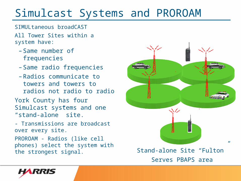
Simulcast Systems and PROROAMSIMULtaneous broadCAST
All Tower Sites within a system have:
– Same number of frequencies
– Same radio frequencies
– Radios communicate to towers and towers to radios not radio to radio
York County has four Simulcast systems and one “stand-alone” site.- Transmissions are broadcast over every site.
PROROAM - Radios (like cell phones) select the system with the strongest signal.
Stand-alone Site “Fulton”
Serves PBAPS area
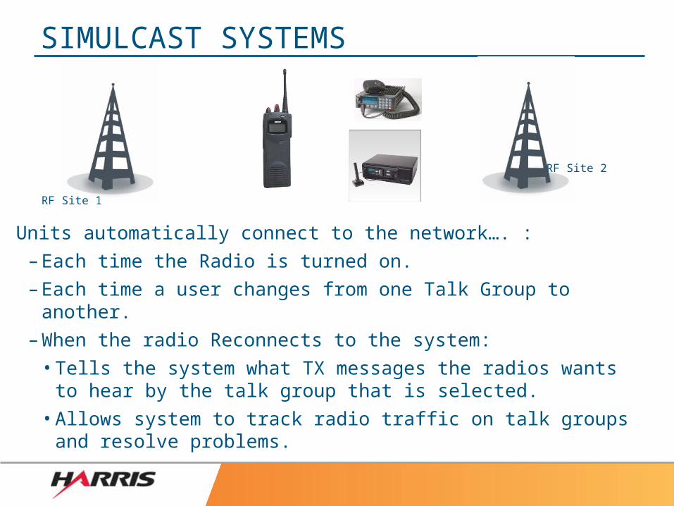
Units automatically connect to the network…. :– Each time the Radio is turned on.
– Each time a user changes from one Talk Group to another.
– When the radio Reconnects to the system:
• Tells the system what TX messages the radios wants to hear by the talk group that is selected.
• Allows system to track radio traffic on talk groups and resolve problems.
SIMULCAST SYSTEMS
RF Site 1
RF Site 2
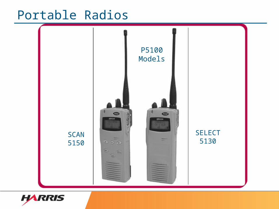
Portable Radios
P5100Models
SCAN5150
SELECT5130
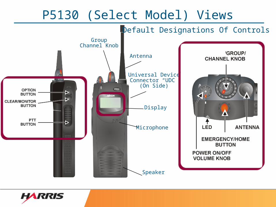
P5130 (Select Model) Views
Antenna
GroupChannel Knob
Display
Universal DeviceConnector “UDC”
(On Side)
Speaker
Microphone
Default Designations Of Controls
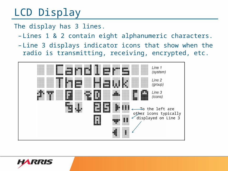
LCD DisplayThe display has 3 lines.
– Lines 1 & 2 contain eight alphanumeric characters.– Line 3 displays indicator icons that show when the radio is
transmitting, receiving, encrypted, etc.
To the left areother icons typically displayed on Line 3
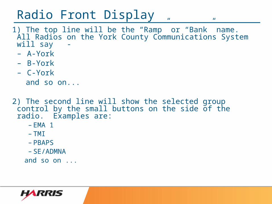
Radio Front Display1) The top line will be the “Ramp” or “Bank” name. All Radios on the York County Communications System will say -– A-York– B-York– C-York
and so on...
2) The second line will show the selected group control by the small buttons on the side of the radio. Examples are:
– EMA 1– TMI– PBAPS– SE/ADMNA
and so on ...
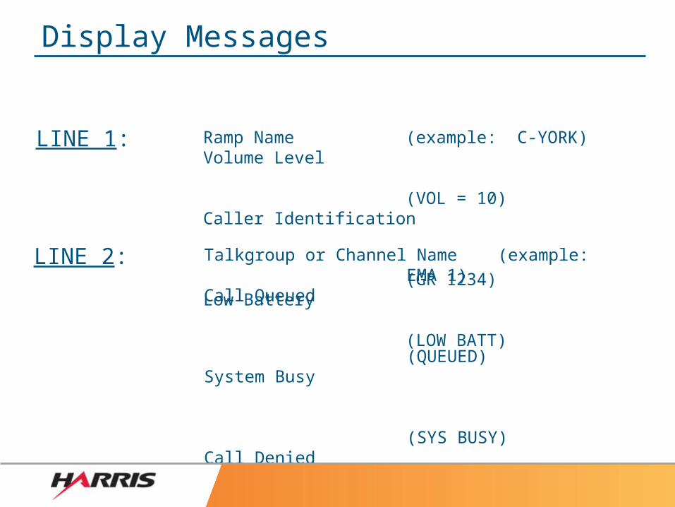
Talkgroup or Channel Name (example: EMA 1)Call Queued
(QUEUED)System Busy
(SYS BUSY)Call Denied
(DENIED)Control Channel Scan
(CC SCAN)Receive Emergency
(*RXEMER*)Transmit Emergency
(*TXEMER*)
Ramp Name (example: C-YORK)Volume Level
(VOL = 10)Caller Identification
(GR 1234)Low Battery
(LOW BATT)
LINE 1:
LINE 2:
Display Messages
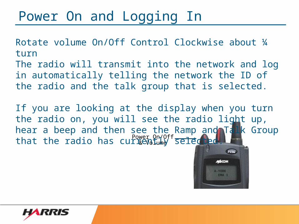
Power On and Logging In
Power On/Off& Volume
A-YORK EMA 1
Rotate volume On/Off Control Clockwise about ¼ turnThe radio will transmit into the network and log in automatically telling the network the ID of the radio and the talk group that is selected.
If you are looking at the display when you turn the radio on, you will see the radio light up, hear a beep and then see the Ramp and Talk Group that the radio has currently selected.
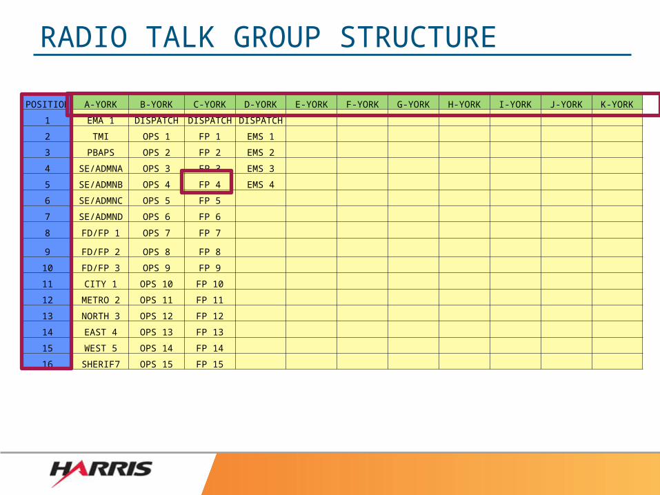
RADIO TALK GROUP STRUCTURE
POSITION A-YORK B-YORK C-YORK D-YORK E-YORK F-YORK G-YORK H-YORK I-YORK J-YORK K-YORK
1 EMA 1 DISPATCH DISPATCH DISPATCH
2 TMI OPS 1 FP 1 EMS 1
3 PBAPS OPS 2 FP 2 EMS 2
4 SE/ADMNA OPS 3 FP 3 EMS 3
5 SE/ADMNB OPS 4 FP 4 EMS 4
6 SE/ADMNC OPS 5 FP 5
7 SE/ADMND OPS 6 FP 6
8 FD/FP 1 OPS 7 FP 7
9 FD/FP 2 OPS 8 FP 8
10 FD/FP 3 OPS 9 FP 9
11 CITY 1 OPS 10 FP 10
12 METRO 2 OPS 11 FP 11
13 NORTH 3 OPS 12 FP 12
14 EAST 4 OPS 13 FP 13
15 WEST 5 OPS 14 FP 14
16 SHERIF7 OPS 15 FP 15
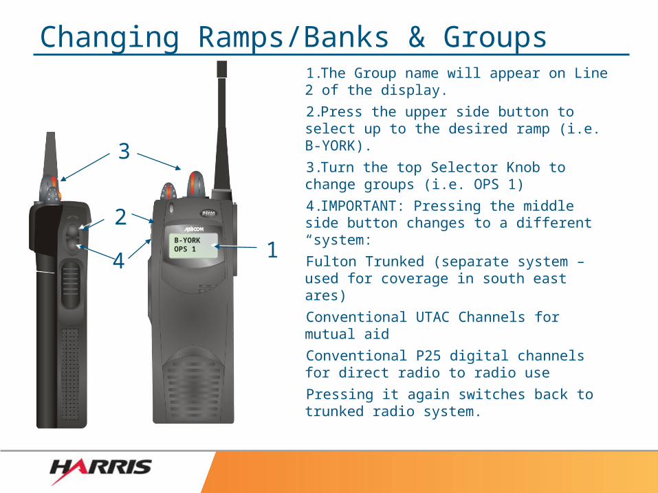
B-YORKOPS 1
22
Changing Ramps/Banks & Groups1.The Group name will appear on Line 2 of the display.
2.Press the upper side button to select up to the desired ramp (i.e. B-YORK).
3.Turn the top Selector Knob to change groups (i.e. OPS 1)
4.IMPORTANT: Pressing the middle side button changes to a different “system:
Fulton Trunked (separate system – used for coverage in south east ares)
Conventional UTAC Channels for mutual aid
Conventional P25 digital channels for direct radio to radio use
Pressing it again switches back to trunked radio system.
1144
33
A-YORK SE/ADMB 4
1
2
3
5
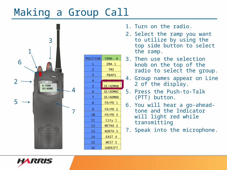
Making a Group Call1. Turn on the radio.2. Select the ramp you want to
utilize by using the top side button to select the ramp.
3. Then use the selection knob on the top of the radio to select the group.
4. Group names appear on Line 2 of the display.
5. Press the Push-to-Talk (PTT) button.
6. You will hear a go-ahead-tone and the Indicator will light red while transmitting
7. Speak into the microphone.
6
7
POSITION YORK- A
1 EMA 1
2 TMI
3 PBAPS
4 SE/ADMNA
5 SE/ADMNB
6 SE/ADMNC
7 SE/ADMND
8 FD/PD 1
9 FD/PD 2
10 FD/PD 3
11 City 1
12 METRO 2
13 NORTH 3
14 EAST 4
15 WEST 5
16 SHERIF7
12345 EMA 1
22
11
33
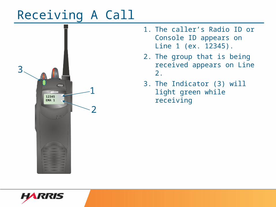
Receiving A Call1. The caller’s Radio ID or
Console ID appears on Line 1 (ex. 12345).
2. The group that is being received appears on Line 2.
3. The Indicator (3) will light green while receiving
A YORK*TXEMER*
1
Top ViewTop View
2233
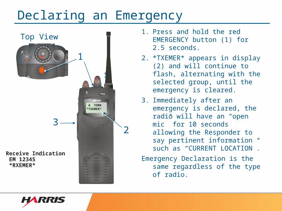
Declaring an Emergency1. Press and hold the red
EMERGENCY button (1) for 2.5 seconds.
2. *TXEMER* appears in display (2) and will continue to flash, alternating with the selected group, until the emergency is cleared.
3. Immediately after an emergency is declared, the radio will have an “open mic” for 10 seconds allowing the Responder to say pertinent information such as “CURRENT LOCATION”.
Emergency Declaration is the same regardless of the type of radio.
11
Receive Indication EM 12345 *RXEMER*
B-YORK OPS 6
1
Top ViewTop View
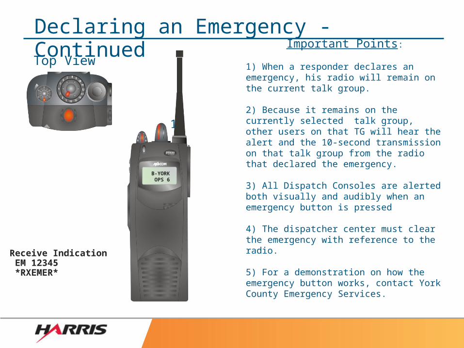
Declaring an Emergency - Continued
Receive Indication EM 12345 *RXEMER*
Important Points:
1) When a responder declares an emergency, his radio will remain on the current talk group.
2) Because it remains on the currently selected talk group, other users on that TG will hear the alert and the 10-second transmission on that talk group from the radio that declared the emergency.
3) All Dispatch Consoles are alerted both visually and audibly when an emergency button is pressed
4) The dispatcher center must clear the emergency with reference to the radio.
5) For a demonstration on how the emergency button works, contact York County Emergency Services.
HOW ARE YOU DOING SO FAR?
True or False:
1) A Simulcast Trunked System communicates from radio to radio directly?– FALSE
2) When a responder presses the emergency button for 2.5 seconds, all other radios in the vicinity make noise to alert them about the emergency?– True
3) In the select radio, pressing the top side button of the radio moves your through the “Banks” or “Ramps” on the radio.– TRUE
Conventional/UTAC Usage
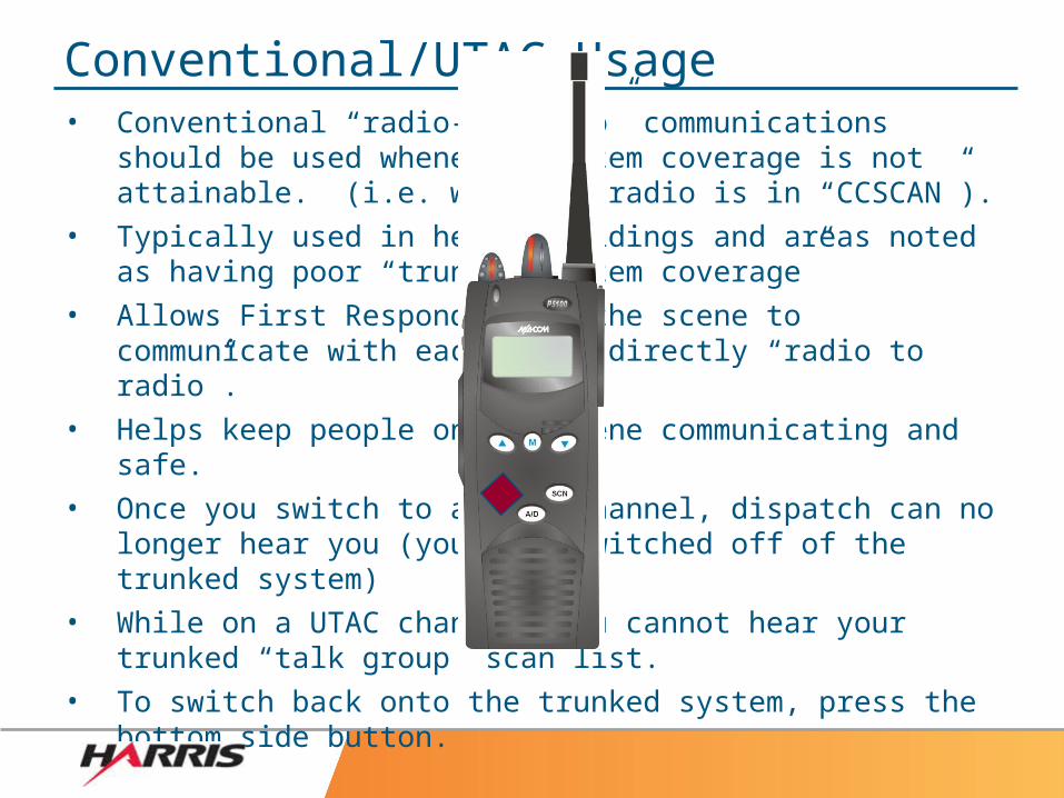
• Conventional “radio-to-radio” communications should be used whenever system coverage is not attainable. (i.e. when the radio is in “CCSCAN”).
• Typically used in heavy buildings and areas noted as having poor “trunked system coverage”
• Allows First Responders on the scene to communicate with each other directly “radio to radio”.
• Helps keep people on the scene communicating and safe.• Once you switch to a UTAC or P25 simplex channel,
dispatch can no longer hear you (you have switched off of the trunked system)
• While on a UTAC channel, you cannot hear your trunked “talk group” scan list.
• To switch back onto the trunked system, press the bottom side button to step back to the main system.
IMPORTANT CONSIDERATIONS
York County uses an all Digital Simulcast System. As a result, there are several things to keep in mind while using the radios.
1) When in an area of weak signal strength, the radio may sound digitally garbled (also described as an “R2D2” sound)
2) When transmitting on one radio while listening to another (or on a scanner) there will be an audio delay. This does two things:– It causes an echo sound that can be xmitted over the radios and
make your audio difficult to understand by other people.
– It can also be confusing to the Responder trying to listen to himself on a scanner or a radio with the delay.
IMPORTANT CONSIDERATIONS
3) The radio microphones perform optimally when the user is speaking in a normal tone, directly into and approx, 4” from the microphone face.
4) Users must wait for the “go ahead tone” before speaking on the radio.
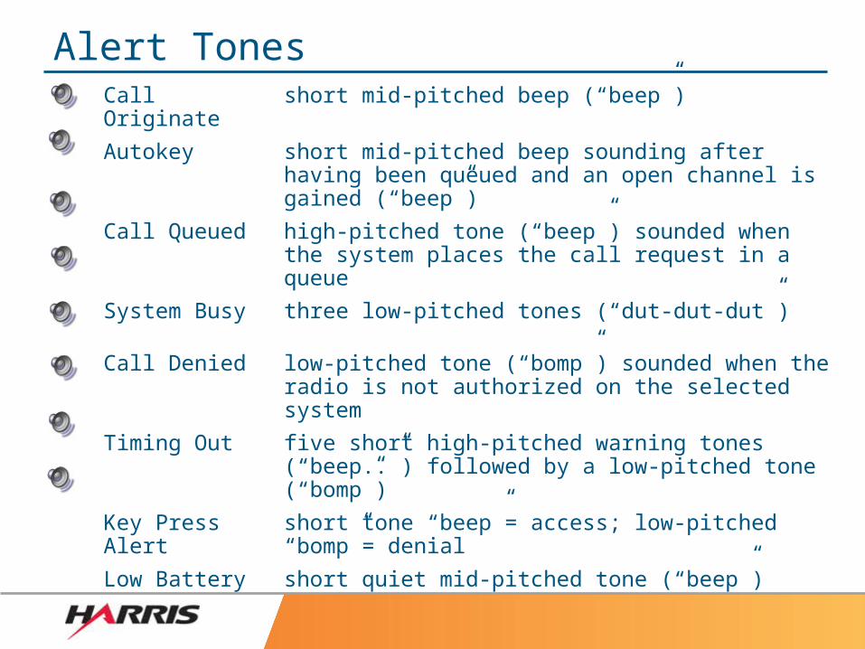
Alert TonesCall Originate short mid-pitched beep (“beep”)
Autokey short mid-pitched beep sounding after having been queued and an open channel is gained (“beep”)
Call Queued high-pitched tone (“beep”) sounded when the system places the call request in a queue
System Busy three low-pitched tones (“dut-dut-dut”)
Call Denied low-pitched tone (“bomp”) sounded when the radio is not authorized on the selected system
Timing Out five short high-pitched warning tones (“beep..”) followed by a low-pitched tone (“bomp”)
Key Press Alert short tone “beep”= access; low-pitched “bomp”= denial
Low Battery short quiet mid-pitched tone (“beep”)
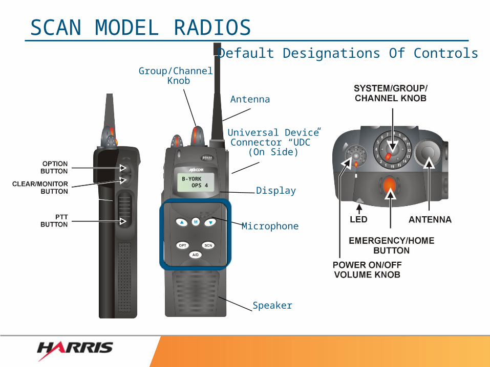
SCAN MODEL RADIOS
Antenna
Group/Channel Knob
Display
Universal DeviceConnector “UDC”
(On Side)
Speaker
Microphone
Default Designations Of Controls
B-YORK OPS 4
LOCKED OPS 4
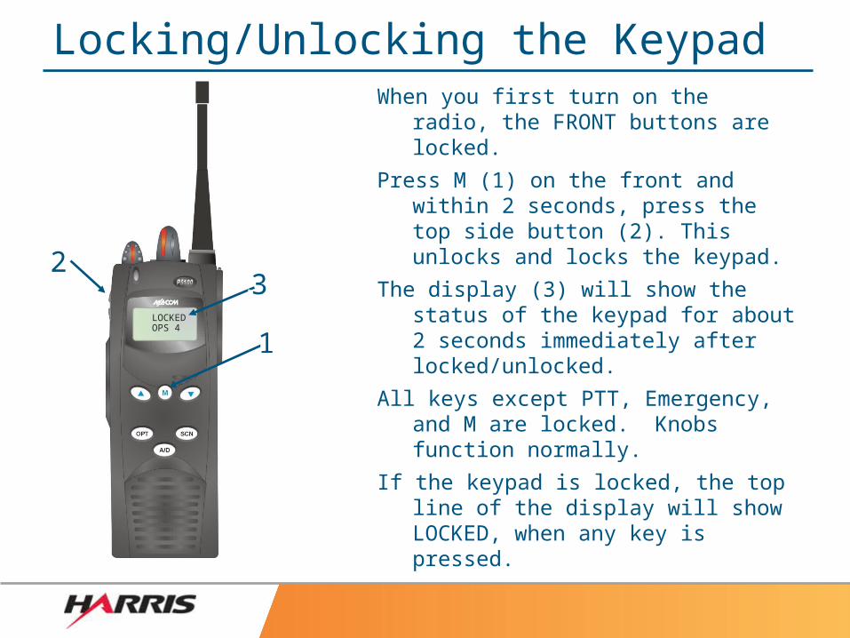
Locking/Unlocking the KeypadWhen you first turn on the radio, the
FRONT buttons are locked.
Press M (1) on the front and within 2 seconds, press the top side button (2). This unlocks and locks the keypad.
The display (3) will show the status of the keypad for about 2 seconds immediately after locked/unlocked.
All keys except PTT, Emergency, and M are locked. Knobs function normally.
If the keypad is locked, the top line of the display will show LOCKED, when any key is pressed.
11
2233
1,3,51,3,5
2,42,4
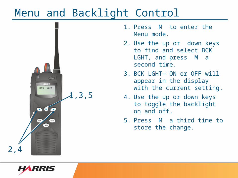
Menu and Backlight Control1. Press M to enter the Menu
mode.
2. Use the up or down keys to find and select BCK LGHT, and press M a second time.
3. BCK LGHT= ON or OFF will appear in the display with the current setting.
4. Use the up or down keys to toggle the backlight on and off.
5. Press M a third time to store the change.
>BCK LGHT
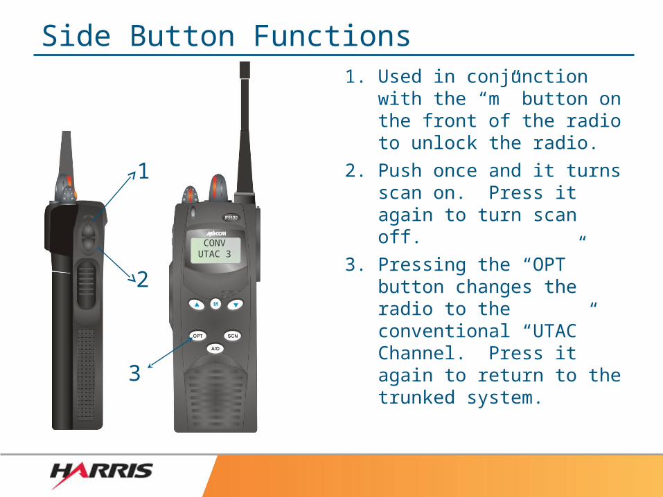
Side Button Functions1. Used in conjunction with
the “m” button on the front of the radio to unlock the radio.
2. Push once and it turns scan on. Press it again to turn scan off.
3. Pressing the “OPT” button changes the radio to the conventional “UTAC” Channel. Press it again to return to the trunked system.
1
2
CONVUTAC 3
3
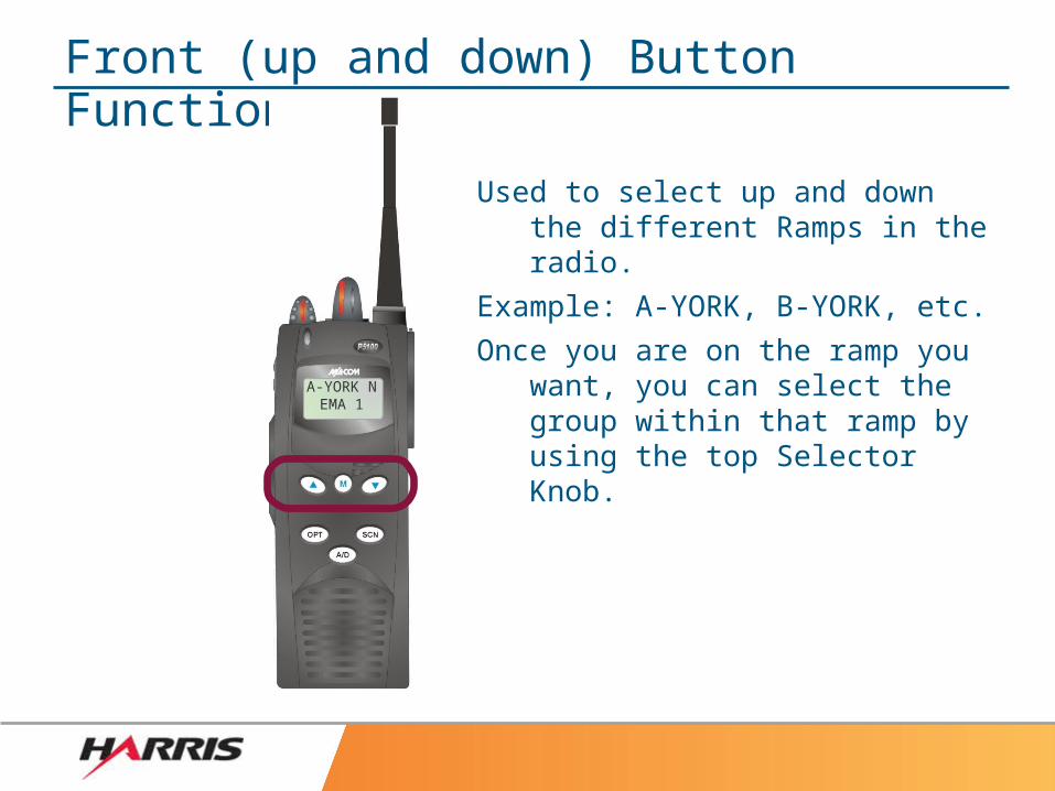
Front (up and down) Button Functions
Used to select up and down the different Ramps in the radio.
Example: A-YORK, B-YORK, etc.
Once you are on the ramp you want, you can select the group within that ramp by using the top Selector Knob.
A-YORK NEMA 1
Conventional/UTAC Usage• Conventional “radio-to-radio” communications should be
used whenever system coverage is not attainable. (i.e. when the radio is in “CCSCAN”).
• Typically used in heavy buildings and areas noted as having poor “trunked system coverage”
• Allows First Responders on the scene to communicate with each other directly “radio to radio”.
• Helps keep people on the scene communicating and safe.• Once you switch to a UTAC channel, dispatch can no longer
hear you (you have switched off of the trunked system)• While on a UTAC channel, you cannot hear your trunked
“talk group” scan list.• To switch back onto the trunked system, press the bottom
side button.
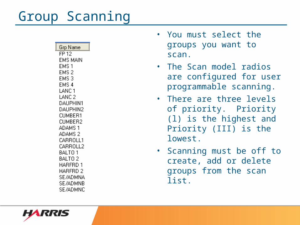
Group Scanning• You must select the groups
you want to scan.• The Scan model radios are
configured for user programmable scanning.
• There are three levels of priority. Priority (l) is the highest and Priority (III) is the lowest.
• Scanning must be off to create, add or delete groups from the scan list.
B-YORK C OPS 2
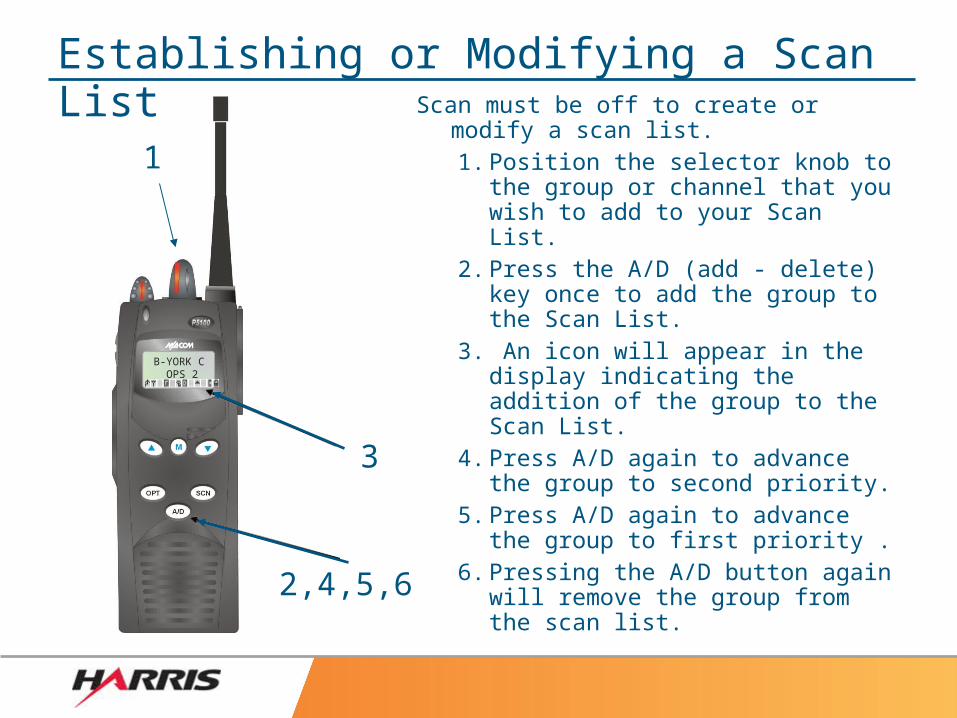
Establishing or Modifying a Scan List Scan must be off to create or
modify a scan list.1. Position the selector knob to the
group or channel that you wish to add to your Scan List.
2. Press the A/D (add - delete) key once to add the group to the Scan List.
3. An icon will appear in the display indicating the addition of the group to the Scan List.
4. Press A/D again to advance the group to second priority.
5. Press A/D again to advance the group to first priority .
6. Pressing the A/D button again will remove the group from the scan list.
1
3
2,4,5,6
C-YORK FP 3
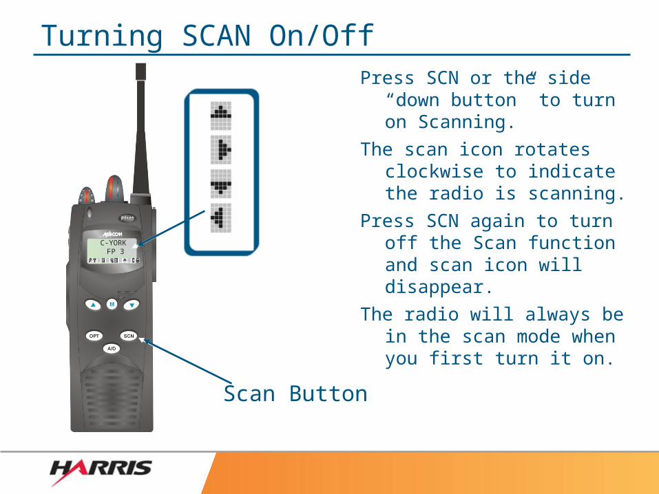
Turning SCAN On/OffPress SCN or the side “down
button” to turn on Scanning.
The scan icon rotates clockwise to indicate the radio is scanning.
Press SCN again to turn off the Scan function and scan icon will disappear.
The radio will always be in the scan mode when you first turn it on.
Scan ButtonScan Button
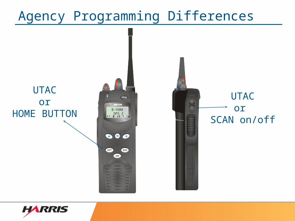
Agency Programming Differences
B-YORK OPS 2
UTACor
SCAN on/off
UTACor
HOME BUTTON
HOW ARE YOU DOING SO FAR:The following questions pertain only to Scan Model Radios:
1) When you turn the radios on they are in the scan mode?• TRUE - Radios are automatically scanning when you turn them
on.
2) The buttons on the face of the radio are “unlocked” by default when you turn the radio on?
• FALSE - The radios face buttons are locked to keep from accidently pressing them.
3) By default, the radio will scan all talk groups?• FALSE - The Responder must select the talk groups he wants to
scan.
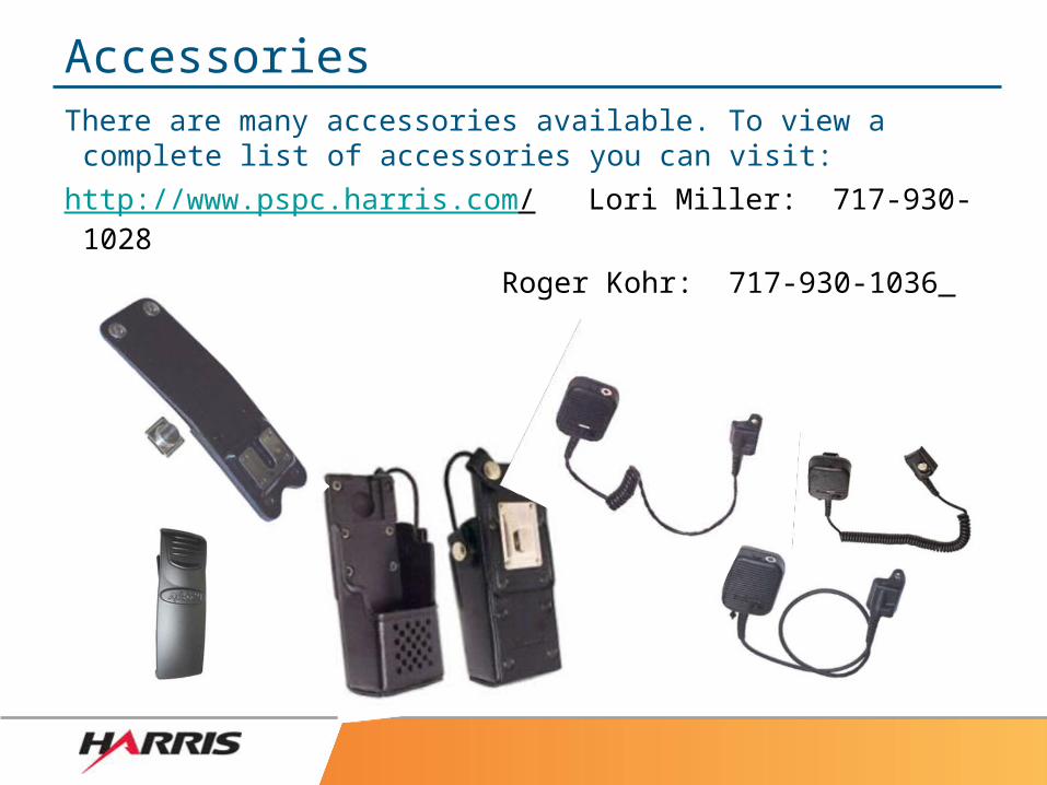
AccessoriesThere are many accessories available. To view a complete list of accessories you can visit:
http://www.pspc.harris.com/ Lori Miller: 717-930-1028
Roger Kohr: 717-930-1036
HOW TO REPORT PROBLEMS
EQUIPMENT PROBLEMS
– Radio hardware issues
– Installation issues
– Equipment warranty issues
– CALL HARRIS DIRECT 1-800-806-0949
COMMUNICATIONS/DISPATCH ISSUES– Issues with communicating on the radios
– Dispatch personnel issues
– CALL YORK COUNTY DISPATCH SUPV. - 1-717-840-2955
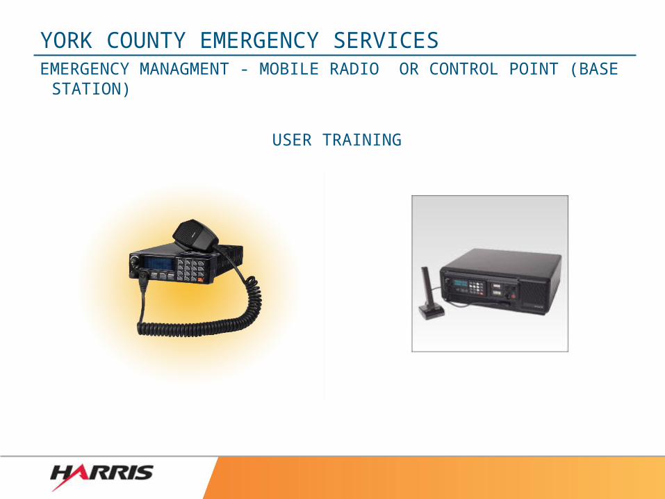
YORK COUNTY EMERGENCY SERVICESEMERGENCY MANAGMENT - MOBILE RADIO OR CONTROL POINT
(BASE STATION)
USER TRAINING
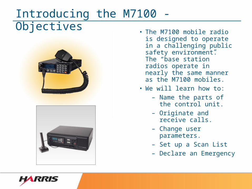
Introducing the M7100 - Objectives
• The M7100 mobile radio is designed to operate in a challenging public safety environment. The “base station” radios operate in nearly the same manner as the M7100 mobiles.
• We will learn how to:– Name the parts of the
control unit.– Originate and receive calls.– Change user parameters.– Set up a Scan List– Declare an Emergency
OPT
CLR
MENU
PHN 0 INDSCAN
A-YORKEMA 1
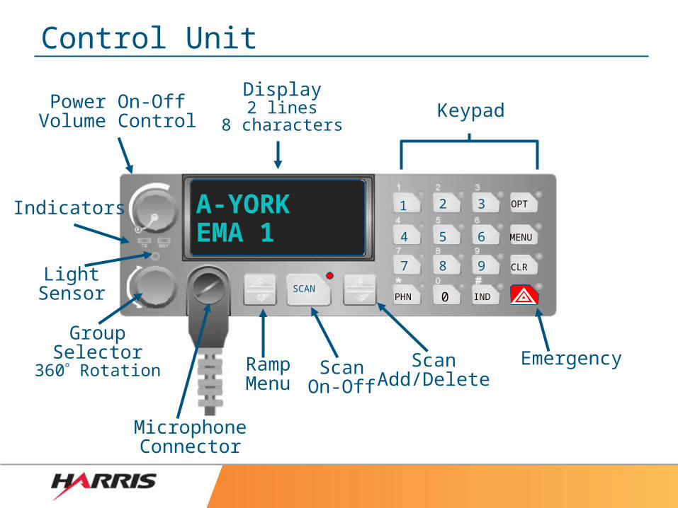
Control Unit
Power On-OffVolume Control
Display2 lines
8 charactersKeypad
LightSensor
GroupSelector
360 Rotation
MicrophoneConnector
RampMenu
ScanOn-Off
ScanAdd/Delete
Indicators
Emergency
1 2 3
4 5 6
7 8 9
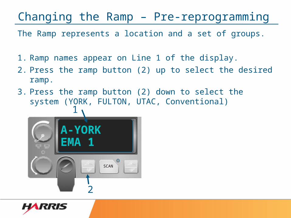
Changing the Ramp – Pre-reprogrammingThe Ramp represents a location and a set of groups.
1. Ramp names appear on Line 1 of the display.
2. Press the ramp button (2) up to select the desired ramp.
3. Press the ramp button (2) down to select the system (YORK, FULTON, UTAC, Conventional)
SCAN
A-YORKEMA 1
2
1
OPT
CLR
MENU
PHN 0 INDSCAN
A-YORKEMA 1
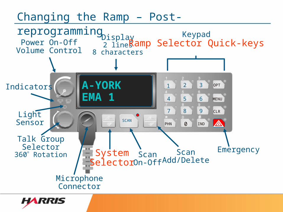
Changing the Ramp – Post-reprogramming
Power On-OffVolume Control
Display2 lines
8 characters
KeypadRamp Selector Quick-keys
LightSensor
Talk GroupSelector
360 Rotation
MicrophoneConnector
SystemSelector
ScanOn-Off
ScanAdd/Delete
Indicators
Emergency
1 2 3
4 5 6
7 8 9
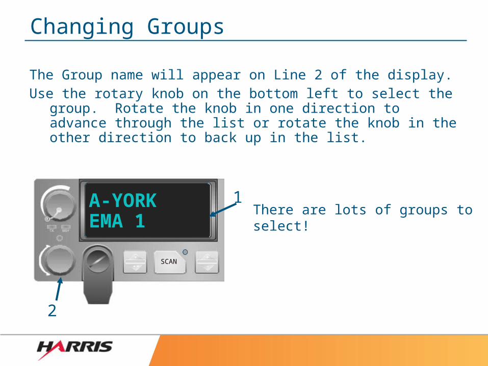
Changing Groups
The Group name will appear on Line 2 of the display.Use the rotary knob on the bottom left to select the group.
Rotate the knob in one direction to advance through the list or rotate the knob in the other direction to back up in the list.
There are lots of groups to select!
SCAN
A-YORKEMA 1
1
2
SCAN
A-YORKEMA 1
4
1
2
35
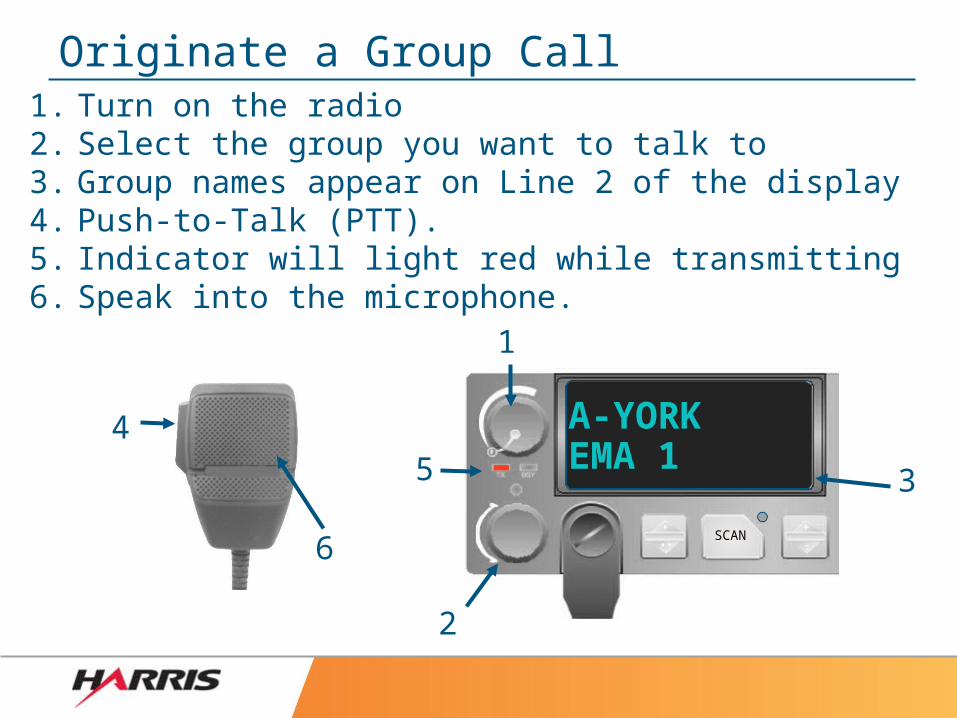
Originate a Group Call
6
1. Turn on the radio2. Select the group you want to talk to3. Group names appear on Line 2 of the display4. Push-to-Talk (PTT).5. Indicator will light red while transmitting6. Speak into the microphone.
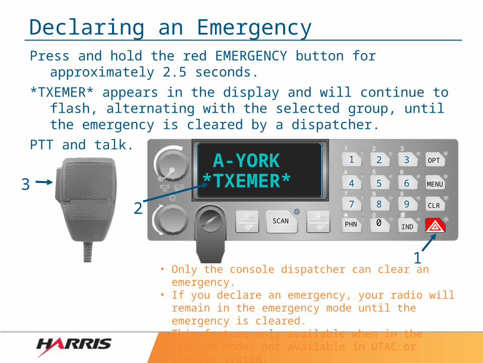
Declaring an EmergencyPress and hold the red EMERGENCY button for approximately
2.5 seconds.
*TXEMER* appears in the display and will continue to flash, alternating with the selected group, until the emergency is cleared by a dispatcher.
PTT and talk.
• Only the console dispatcher can clear an emergency.• If you declare an emergency, your radio will remain in
the emergency mode until the emergency is cleared.• This feature only available when in the trunked mode,
not available in UTAC or simplex system.
OPT
CLR
MENU
PHN 0 INDSCAN
A-YORK*TXEMER*3
1
2
1 2 3
4 5 6
7 8 9
PHN 0 INDSCAN
A-YORK EMA 1
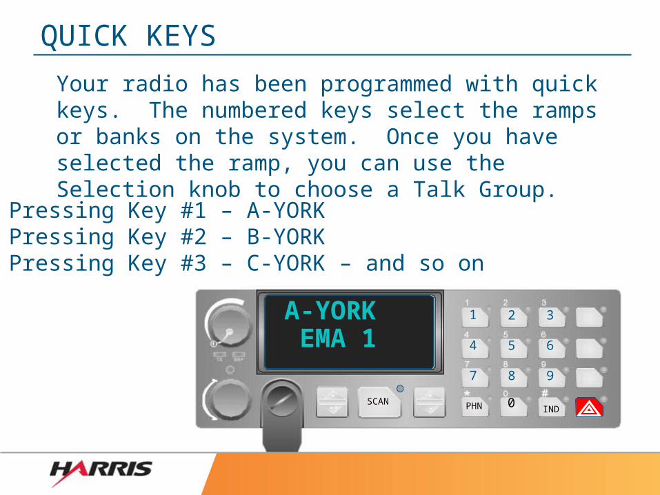
QUICK KEYS
1 2 3
4 5 6
7 8 9
Your radio has been programmed with quick keys. The numbered keys select the ramps or banks on the system. Once you have selected the ramp, you can use the Selection knob to choose a Talk Group.
Pressing Key #1 – A-YORKPressing Key #2 – B-YORKPressing Key #3 – C-YORK – and so on
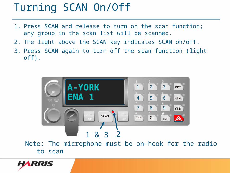
Turning SCAN On/Off
1. Press SCAN and release to turn on the scan function; any group in the scan list will be scanned.
2. The light above the SCAN key indicates SCAN on/off.
3. Press SCAN again to turn off the scan function (light off).
OPT
CLR
MENU
PHN 0 INDSCAN
A-YORKEMA 1
Note: The microphone must be on-hook for the radio to scan
1 & 3 2
1 2 3
4 5 6
7 8 9
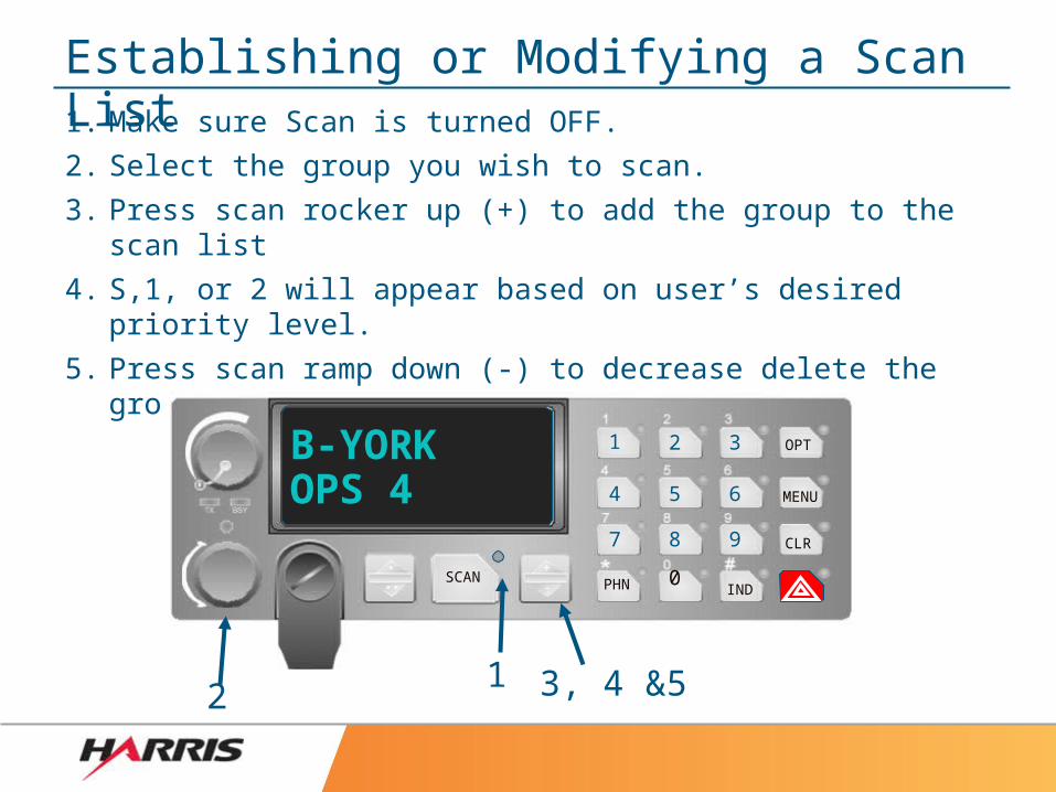
Establishing or Modifying a Scan List1. Make sure Scan is turned OFF.
2. Select the group you wish to scan.
3. Press scan rocker up (+) to add the group to the scan list
4. S,1, or 2 will appear based on user’s desired priority level.
5. Press scan ramp down (-) to decrease delete the group from the Scan List.
OPT
CLR
MENU
PHN 0IND
SCAN
B-YORKOPS 4
21 3, 4 &5
1 2 3
4 5 6
7 8 9
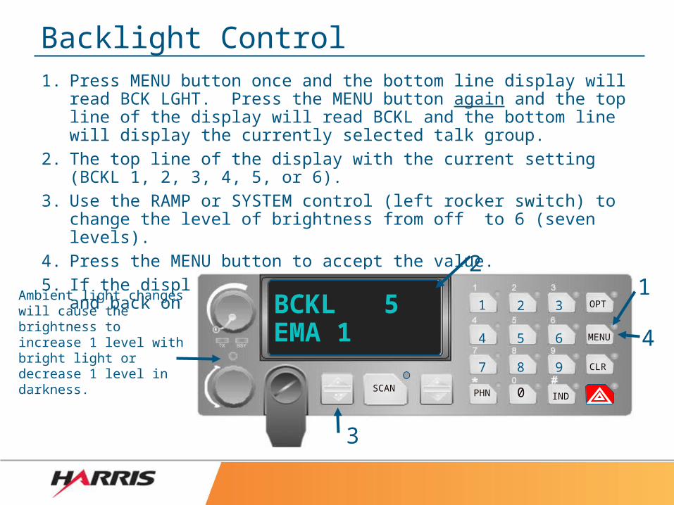
Backlight Control1. Press MENU button once and the bottom line display will read BCK
LGHT. Press the MENU button again and the top line of the display will read BCKL and the bottom line will display the currently selected talk group.
2. The top line of the display with the current setting (BCKL 1, 2, 3, 4, 5, or 6).
3. Use the RAMP or SYSTEM control (left rocker switch) to change the level of brightness from off to 6 (seven levels).
4. Press the MENU button to accept the value.5. If the display is set to off, powering the radio off and back on will
power up the radio to display of 1.OPT
CLR
MENU
PHN 0 INDSCAN
BCKL 5EMA 1
3
1
4
2Ambient light changes will cause the brightness to increase 1 level with bright light or decrease 1 level in darkness.
1 2 3
4 5 6
7 8 9
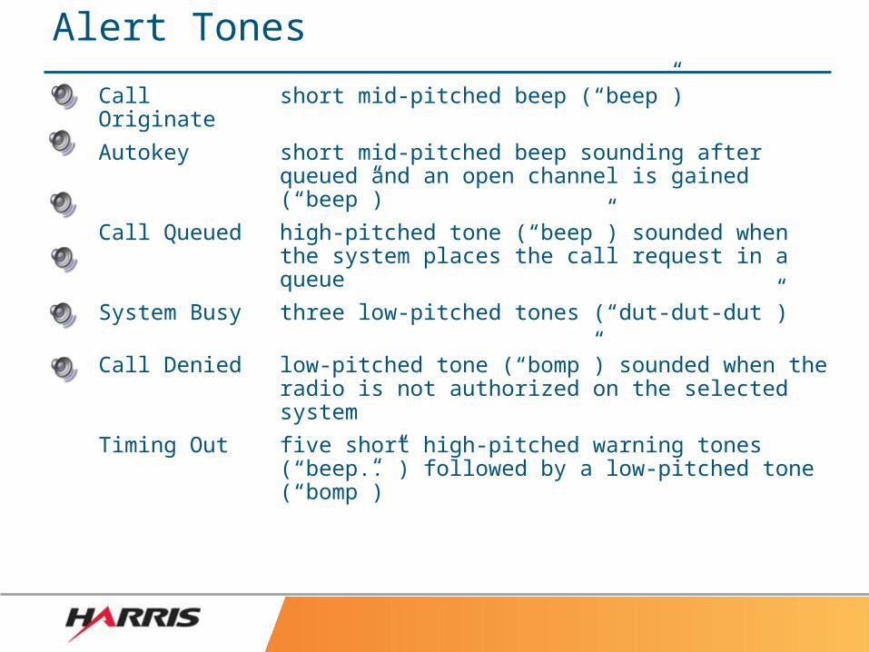
Alert Tones
Call Originate short mid-pitched beep (“beep”)
Autokey short mid-pitched beep sounding after queued and an open channel is gained (“beep”)
Call Queued high-pitched tone (“beep”) sounded when the system places the call request in a queue
System Busy three low-pitched tones (“dut-dut-dut”)
Call Denied low-pitched tone (“bomp”) sounded when the radio is not authorized on the selected system
Timing Out five short high-pitched warning tones (“beep..”) followed by a low-pitched tone (“bomp”)
QUESTIONS
If you have questions please contact:
Bill James: 717-840-2914 [email protected]
OR
Nate Kirschman: 717-434-5842 or 717-840-2925 [email protected]


