34
Group Members: Saad Asghar Junaid Akbar Ziafat Ali
| Date post: | 18-Nov-2014 |
| Category: |
Documents |
| Upload: | engr-syed-ziafat-ali |
| View: | 122 times |
| Download: | 3 times |
Group Members:
Saad Asghar
Junaid Akbar
Ziafat Ali

Introduction to radio wave propagation. Types of propagation. Line of sight & Tropospheric
communication. Polarization for different kinds of
propagation. Attenuation in wave propagation.
Topics

Introduction to Radio Wave Propagation
Radio waves are also called EM waves. An EM wave radiated by transmitting antenna is a transverse wave. A transverse wave is also called traveling wave.
Radio waves propagate in a straight line in several directions at once. In a vacuum, radio waves propagate at 3*10^8 m/s.


Types of propagation.
Ground wave or surface wave. Space wave or tropospheric
wave. Sky wave or ionospheric wave

Ground-Wave Propagation (Surface wave):
A part of wave travels along or near the surface of the earth.
Useful at low frequencies.
Useful for communication at VLF,LF and MF.
Vertically polarized because lesser energy is absorbed in it.
As the wave travels, level becomes lesser due to attenuation.
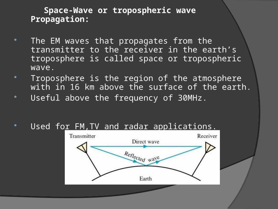
Space-Wave or tropospheric wave Propagation:
The EM waves that propagates from the transmitter to the receiver in the earth’s troposphere is called space or tropospheric wave.
Troposphere is the region of the atmosphere with in 16 km above the surface of the earth.
Useful above the frequency of 30MHz.
Used for FM,TV and radar applications.
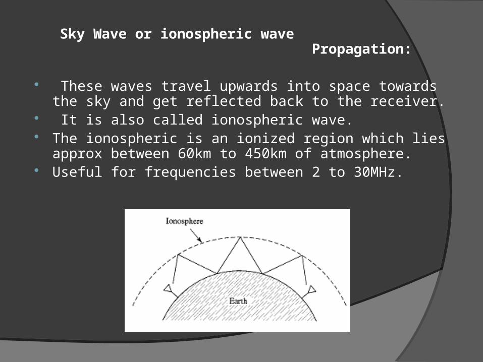
Sky Wave or ionospheric wave Propagation:
These waves travel upwards into space towards the sky and get reflected back to the receiver.
It is also called ionospheric wave. The ionospheric is an ionized region which lies approx
between 60km to 450km of atmosphere. Useful for frequencies between 2 to 30MHz.
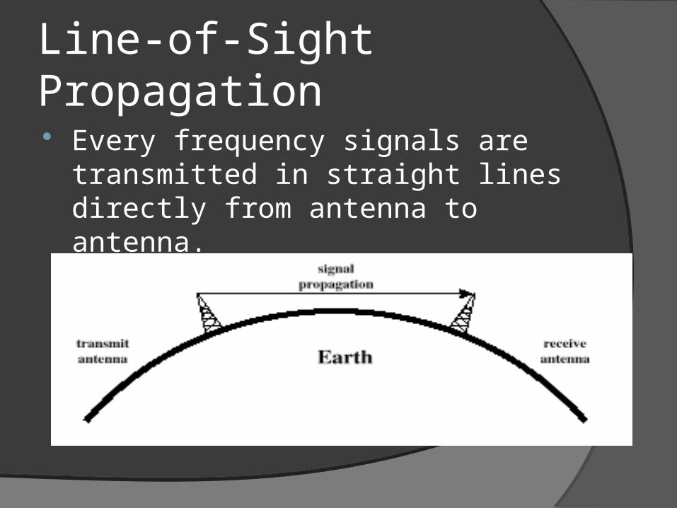
Line-of-Sight Propagation
Every frequency signals are transmitted in straight lines directly from antenna to antenna.

Line-of-Sight Propagation
It was difficult to install cable in rocky hills and across rivers and lakes.
To communicate by line of sight mode, you must be able to see the other station from your antenna
Line-of-Sight Propagation That means the higher the antennas, the
longer the distance that can be reached. Line of sight propagation works at almost
any frequency, it is of importance at VHF, UHF and microwave frequencies
On the HF frequencies, it really isn’t very useful, since we are generally interested in communicating over much great distances.

Line-of-Sight Propagation
Optical line of sight
Effective, or radio, line of sight
○ d = distance between antenna and horizon (km)○ h = antenna height (m)○ K = adjustment factor to account for refraction, rule of
thumb K = 4/3
hd 57.3
hd 57.3
Line-of-Sight Propagation
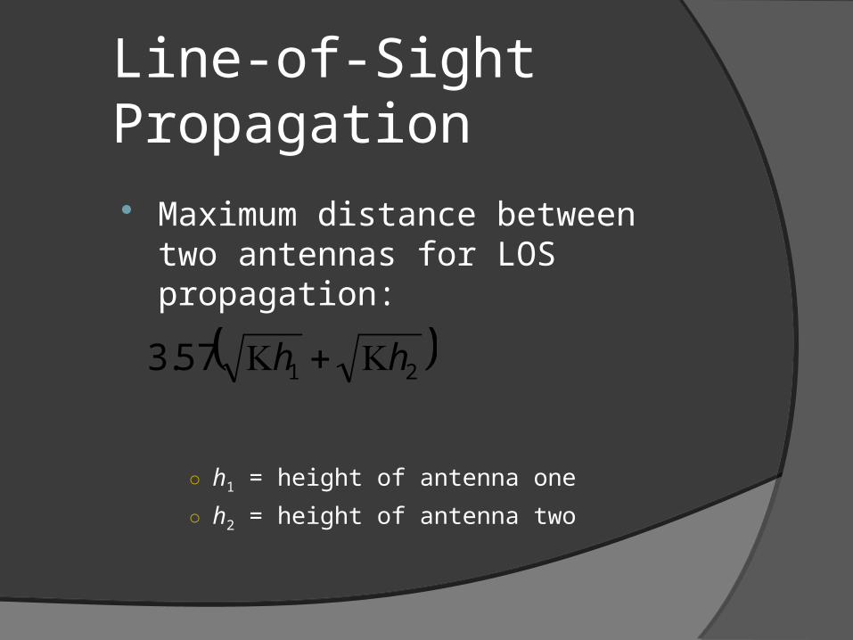
Maximum distance between two antennas for LOS propagation:
○ h1 = height of antenna one
○ h2 = height of antenna two
2157.3 hh
TROPOSPHERIC PROPAGATION
The troposphere extends from the Earth's lowest region of the Earth's atmosphere surface to a height of slightly over 7 miles.
All weather phenomena occur in this region.
Conti…….
Troposphere is characterized by a steady decrease in both temperature and pressure as height is increased.
Changes in weather phenomena cause variations in humidity and an uneven heating of the Earth's surface

Conti…..
The air in the troposphere is in constant motion.
This motion causes small turbulences, to be formed,
The bouncing of aircraft entering turbulent areas of the atmosphere
.

Conti….
Radio waves are affected very little by the turbulences
These turbulences are most intense near the Earth's surface and gradually diminish with height.
They have a refractive quality that permits the refracting or scattering of radio waves with short wavelengths.

Conti….. This scattering provides better
communications at higher frequencies. The relationship between frequency and
wavelength are inversely proportional. Radio waves of frequencies below 30
megahertz normally have wavelengths longer than the size of weather turbulences.

Conti…..
The frequency increases into the VHF range and above, the wavelengths decrease in size, To the point that they become subject to tropospheric scattering.
frequency range 100 megahertz to 10 gigahertz.

Conti……..
The total received signal is an accumulation of the energy received from each of the turbulences
APPLICATION OF TROPOSPHERIC SCATTERING Tropospheric scatter propagation is used for
point-to-point communications. A correctly designed tropospheric scatter
circuit will provide highly reliable service for distances ranging from 50 miles to 500 miles.
Polarization
Polarization (also polarisation) is a property of waves that describes the orientation of their oscillations. Electromagnetic wave such as light, along with other types of wave, exhibit polarization. The plane of polarization of a radio wave is the plane in which the E field propagates with respect to the Earth.
Polarization types
Horizontal Polarization
If the E field propagates in a plane parallel to the Earth's surface (horizontal), the radiation is said to
be horizontally polarized. Vertical Polarization
If the E field component of the radiated wave travels in a plane perpendicular to the Earth's surface (vertical), the radiation is said to be vertically polarized.
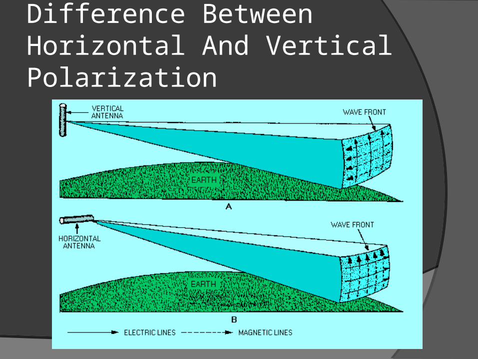
Difference Between Horizontal And Vertical Polarization

Polarization For Different types of Propagation Propagation Ground-wave -Are at medium and low frequencies.
-Horizontal polarization cannot be used 1. Earth acts as a fairly good conductor . 2. Electric lines of force would become parallel to Earth. Propagation Sky-wave -Are at high frequencies -Either horizontally or vertically polarized 1. Sky-waves are elliptically polarized.
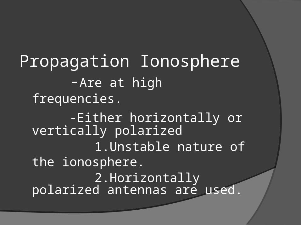
2. Travel obliquely through the Earth's magnetic field. Propagation Ionosphere -Are at high frequencies. -Either horizontally or vertically polarized
1.Unstable nature of the ionosphere. 2.Horizontally polarized antennas are used.

Propagation Ground-wave -Are at medium and low frequencies.
-Horizontal polarization cannot be used 1. Earth acts as a fairly good
conductor . 2. Electric lines of force would
become parallel to Earth.

Propagation Sky-wave -Are at high frequencies -Either horizontally or vertically
polarized 1. Sky-waves are elliptically
polarized. 2. Travel obliquely through the
Earth's magnetic field.
Propagation Ionosphere -Are at high frequencies. -Either horizontally or vertically
polarized
1.Unstable nature of the ionosphere. 2.Horizontally polarized antennas
are used.
Advantages of Horizontal Polarization
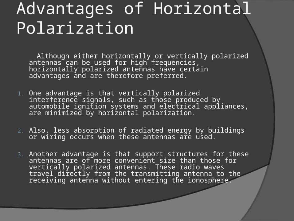
Although either horizontally or vertically polarized antennas can be used for high frequencies, horizontally polarized antennas have certain advantages and are therefore preferred.
1. One advantage is that vertically polarized interference signals, such as those produced by automobile ignition systems and electrical appliances, are minimized by horizontal polarization.
2. Also, less absorption of radiated energy by buildings or wiring occurs when these antennas are used.
3. Another advantage is that support structures for these antennas are of more convenient size than those for vertically polarized antennas. These radio waves travel directly from the transmitting antenna to the receiving antenna without entering the ionosphere.
Advantages of Vertical Polarization
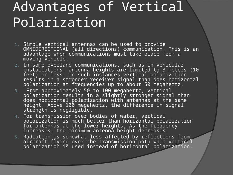
1. Simple vertical antennas can be used to provide OMNIDIRECTIONAL (all directions) communication. This is an advantage when communications must take place from a moving vehicle.
2. In some overland communications, such as in vehicular installations, antenna heights are limited to 3 meters (10 feet) or less. In such instances vertical polarization results in a stronger receiver signal than does horizontal polarization at frequencies up to about 50 megahertz.
3. From approximately 50 to 100 megahertz, vertical polarization results in a slightly stronger signal than does horizontal polarization with antennas at the same height. Above 100 megahertz, the difference in signal strength is negligible.
4. For transmission over bodies of water, vertical polarization is much better than horizontal polarization for antennas at the lower heights. As the frequency increases, the minimum antenna height decreases.
5. Radiation is somewhat less affected by reflections from aircraft flying over the transmission path when vertical polarization is used instead of horizontal polarization.

Attenuation Attenuation indicates the rate at which the
wave amplitude reduces as it propagates from one point to another.
Radio waves don't travel the same distance in all directions. Walls, doors, elevator shafts, people, and other obstacles offer varying degrees of attenuation, which cause the Radio Frequency (RF) radiation pattern to be irregular and unpredictable.

Continued… Attenuation is simply a reduction of signal strength
during transmission.
Attenuation is registered in decibels (dB), which is twenty times the logarithm of the signal power at a particular input divided by the signal power at an output of a specified medium.
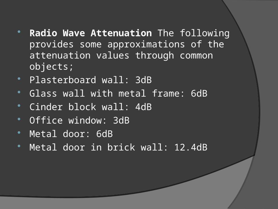
Radio Wave Attenuation The following provides some approximations of the attenuation values through common objects;
Plasterboard wall: 3dB Glass wall with metal frame: 6dB Cinder block wall: 4dB Office window: 3dB Metal door: 6dB Metal door in brick wall: 12.4dB

THANK YOU


