Radioactive Ion Beams at the HRIBF Present Status and Future Development Plans HRIBF Workshop - Near and Sub-barrier Fusion of Radioactive Ions with Medium and Heavy Targets December 2-3, 2005 Oak Ridge, TN Dan Stracener Physics Division, ORNL 1 OAK RIDGE NATIONAL LABORATORY U.S. DEPARTMENT OF ENERGY
Transcript
Radioactive Ion Beams at the HRIBFPresent Status and Future Development Plans
HRIBF Workshop - Near and Sub-barrier Fusion of Radioactive Ions with Medium and Heavy Targets
December 2-3, 2005Oak Ridge, TN
Dan StracenerPhysics Division, ORNL
1
OAK RIDGE NATIONAL LABORATORYU.S. DEPARTMENT OF ENERGY
2
OAK RIDGE NATIONAL LABORATORYU.S. DEPARTMENT OF ENERGY
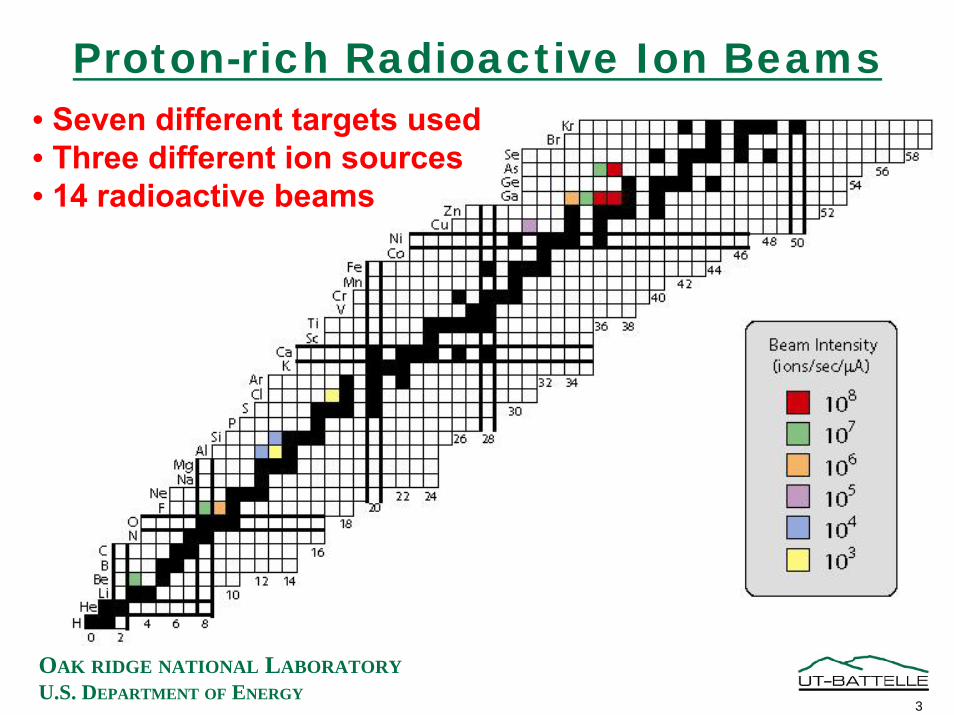
Proton-rich Radioactive Ion Beams• Seven different targets used• Three different ion sources• 14 radioactive beams
3
OAK RIDGE NATIONAL LABORATORYU.S. DEPARTMENT OF ENERGY
Accelerated Proton-richRadioactive Ion Beams
RIB Energy Range Highest Intensity ORIC Current Purity(MeV) (pps on target) (µA on target)
7Be 4 - 100 2.0 x 10⁷ n/a 1003
1.555
0.01
(%)
17F 10-170 1.0 x 10⁷ 10018F 10-108 6.0 x 10⁵ 100
67Ga 160 2.5 x 10⁵ > 9069As 160 2.0 x 10⁶ ~ 10
70As* 140 2.0 x 10³ < 10-6
* This beam was used for commissioning of the RIB Injector
4
OAK RIDGE NATIONAL LABORATORYU.S. DEPARTMENT OF ENERGY
Available Neutron-rich Radioactive Ion Beams(over 110 beams with intensities ≥103 ions/sec)
E/A = 3 MeV/amuE/A = 3 MeV/amu
5
OAK RIDGE NATIONAL LABORATORYU.S. DEPARTMENT OF ENERGY
OAK RIDGE NATIONAL LABORATORYU.S. DEPARTMENT OF ENERGY
Accelerated n-rich RIBs (A>100 amu)RIB Energy Range (MeV) Highest Intensity (pps) Purity (%)
117Ag 460 1.2 x 10⁶ 95118Ag 236 – 455 1.7 x 10⁶ 90
131Sn 550 2.5 x 10⁵ > 99
136Sn 400 3 0.2129Sb 400 2.9 x 10⁷ 49
126Sn 378 1.0 x 10⁷ 50128Sn 384 3.0 x 10⁶ > 99130Sn 391 – 550 5.0 x 10⁵ > 99
132Sn 316 8.6 x 10⁵ 96132Sn 453 – 620 1.5 x 10⁵ 96133Sn 316 1.7 x 10⁴ 33134Sn 316 – 560 2.8 x 10³ 38
132Te 350 – 396 3.0 x 10⁷ 87
136Te 396 – 470 5.0 x 10⁵ 80
134Te 396 – 565 2.4 x 10⁶ 95
7
OAK RIDGE NATIONAL LABORATORYU.S. DEPARTMENT OF ENERGY
Beams Available at the HRIBF
8
OAK RIDGE NATIONAL LABORATORYU.S. DEPARTMENT OF ENERGY
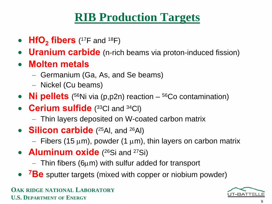
RIB Production Targets
• HfO2 fibers (17F and 18F)• Uranium carbide (n-rich beams via proton-induced fission)• Molten metals
− Germanium (Ga, As, and Se beams)− Nickel (Cu beams)
• Ni pellets (56Ni via (p,p2n) reaction – 56Co contamination)• Cerium sulfide (33Cl and 34Cl)
− Thin layers deposited on W-coated carbon matrix• Silicon carbide (25Al, and 26Al)
− Fibers (15 µm), powder (1 µm), thin layers on carbon matrix• Aluminum oxide (26Si and 27Si)
− Thin fibers (6µm) with sulfur added for transport• 7Be sputter targets (mixed with copper or niobium powder)
9
OAK RIDGE NATIONAL LABORATORYU.S. DEPARTMENT OF ENERGY
• 300 kV (design) platform• 2-stage mass separation
− M/∆M ~ 1000− M/∆M ~ 20000
• Robotic handling of activated targets and ion sources
Radioactive Ion BeamInjector System
10
OAK RIDGE NATIONAL LABORATORYU.S. DEPARTMENT OF ENERGY
RIB Development and Testing Facilities
• Ion Source Test Facility I (ISTF-1)− characterize ion sources (efficiency, longevity, emittance, energy
spread, effusion)− some target tests (e.g. effusion through matrix)− ion cooler for negative ions (gas-filled RFQ)
• Ion Source Test Facility II (ISTF-2)− laser ion source− ECR ion source
• On-Line Test Facility (OLTF)− low intensity tests of target and ion source performance− compatible with the RIB Injector and results are scaleable
• High Power Target Laboratory (HPTL)− NOW available for target tests using high power beams from ORIC
11
OAK RIDGE NATIONAL LABORATORYU.S. DEPARTMENT OF ENERGY
Ion Source Test Facility I (ISTF-1)
12
OAK RIDGE NATIONAL LABORATORYU.S. DEPARTMENT OF ENERGY
Laser-induced Photodetachment of Ni¯ and Co¯in a He-filled RFQ Ion Cooler
0
20
40
60
80
100
0 10 20 30 40 50 60
t (s)
Ion
Cur
rent
(%)
59Co-58Ni-
Laser off
Laser on
Laser on
Neutralization: Co¯: ~95%Ni ¯: ~10%
• Laser: Nd:YAG, 5 W, CW, 1064 nm• About 50% of laser beam passed through the RFQ (40 cm long)• The energy of the negative ions was reduced from 5 keV to <50 eV in the cooler• Laser interaction time in the RFQ cooler is on the order of 1 ms
13
OAK RIDGE NATIONAL LABORATORYU.S. DEPARTMENT OF ENERGY
Ion Source Test Facility II (ISTF-2)
Ion SourceEinzel Lens
Emittance Measurement Device
Faraday Cup
Faraday Cup
Mass Analyzing Magnet
High Voltage Insulator
High Voltage Platform
Motor Generator
Fence
High-Voltage Interlocked Sliding Door
14
OAK RIDGE NATIONAL LABORATORYU.S. DEPARTMENT OF ENERGY
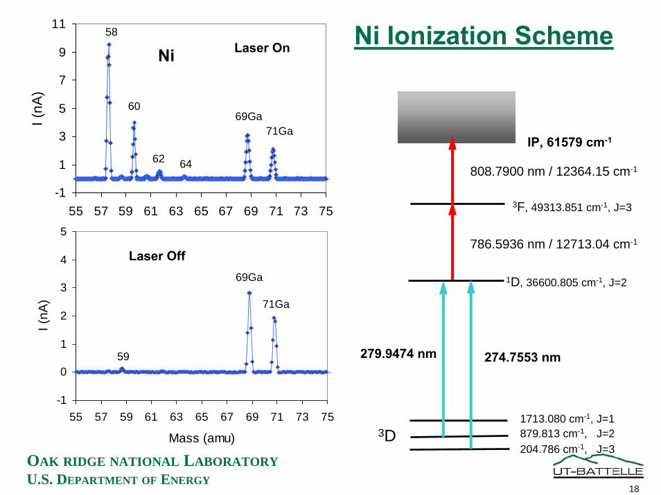
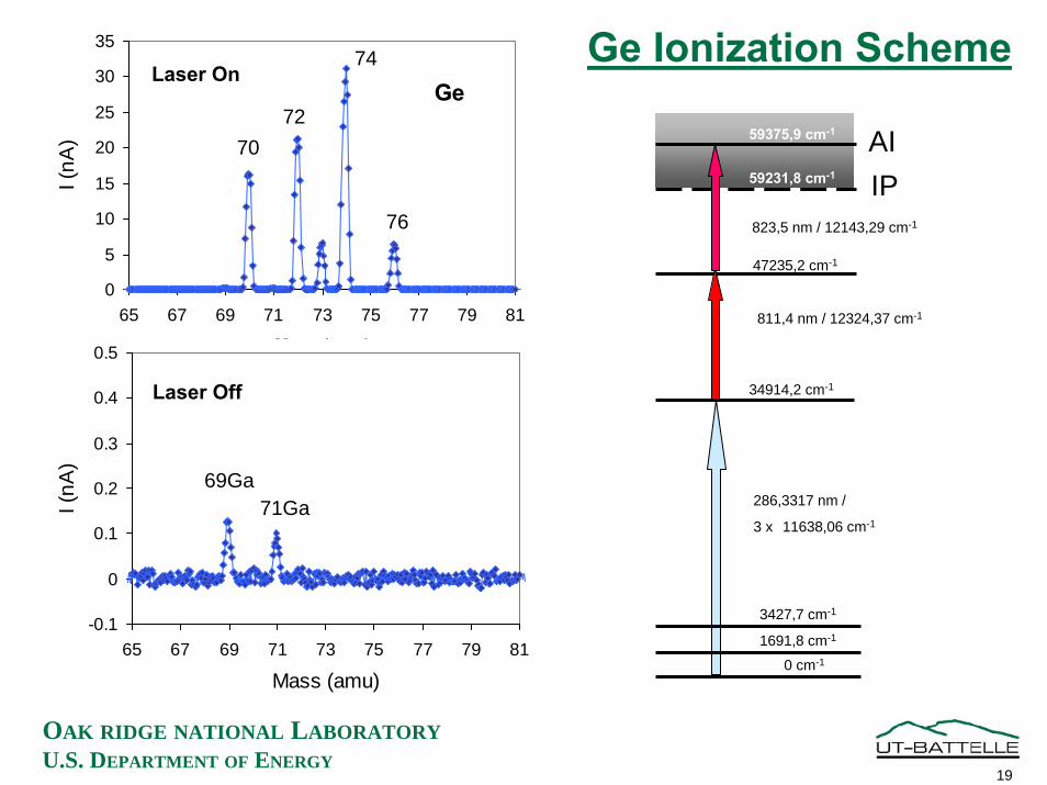
Laser Ion Source Experiments (8/31/04 – 9/23/04)
• Laser ion source set up and operated at HRIBF in collaboration with a group from Mainz (Klaus Wendt and students)
• Three-step ionization of Sn, Ge, and Ni obtained• Last ionization step:
− autoionization state for Sn and Ge• No surface ionized Sn, Ge, and Ni ions observed
OAK RIDGE NATIONAL LABORATORYU.S. DEPARTMENT OF ENERGY
20
OAK RIDGE NATIONAL LABORATORYU.S. DEPARTMENT OF ENERGY
Beam from Tandem Accelerator
Beam Diagnostics
Dipole MagnetM/∆M = 2000
Charge ExchangeMeasurement System
Moving Tape Systemand γ-ray Detector
Target / Ion Source
On-Line Target and Ion Source Testing Facility
TIS Fabrication Area
Mass Measurements
HfO2 Fiber Target for Production of 17,18F Beams
• Thin Fibers (5 µm) - fast diffusion• High porosity (density is 1.15 g/cm3)• Refractory (m.p. is 2770 C)• Free of volatile impurities• 4 rolls of HfO2 cloth used for target
− 1.5 cm diameter x 1 cm thick each• Al2O3 felt sheath
− Provides aluminum vapor− Fluorine is transported as AlF molecule
• HfO2 cloth sheath− Keeps alumina away from the Ta wall Beam
HfO2
Al2O3
21
OAK RIDGE NATIONAL LABORATORYU.S. DEPARTMENT OF ENERGY
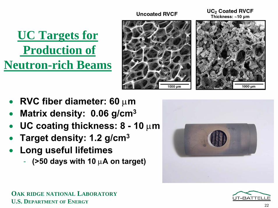
• Long useful lifetimes- (>50 days with 10 µA on target)
22
OAK RIDGE NATIONAL LABORATORYU.S. DEPARTMENT OF ENERGY
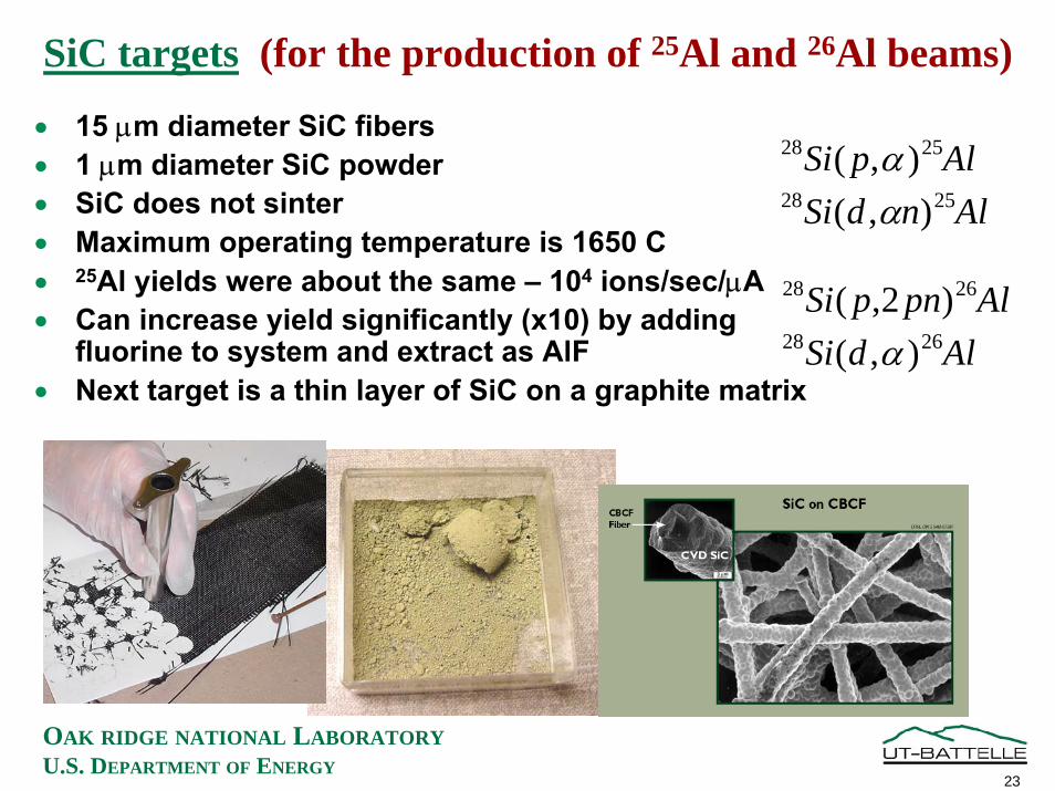
SiC targets (for the production of 25Al and 26Al beams)
• 15 µm diameter SiC fibers• 1 µm diameter SiC powder• SiC does not sinter• Maximum operating temperature is 1650 C• 25Al yields were about the same – 104 ions/sec/µA• Can increase yield significantly (x10) by adding
fluorine to system and extract as AlF• Next target is a thin layer of SiC on a graphite matrix
AlpSi 2528 ),( αAlndSi 2528 ),( α
AlpnpSi 2628 )2,(AldSi 2628 ),( α
23
OAK RIDGE NATIONAL LABORATORYU.S. DEPARTMENT OF ENERGY
Production Rates for Sn, Sb, Te, and I isotopes in a UC target
Production Rate from proton-induced fission in uranium(using 40 MeV protons)
OAK RIDGE NATIONAL LABORATORYU.S. DEPARTMENT OF ENERGY
Intensities for Sn, Sb, and Te Isotopes
A=132
A=133
A=134
Sn
Sb
Te
− Measured with Bragg detector (gas chamber)
− Beam energy is 316 MeV− 132Sn beam intensity is 8.6x10⁵
pps (96% of total)− 133Sn beam intensity is 1.5x10⁴
pps (33% of total)− 134Sn beam intensity is 2.8x10³
pps (38% of total)− These beams were extracted
as sulfide molecules from the ion source
− The percentages of Sn in the atomic ion beams are <1%
− The 134Sb/133Sb ratio is small due to a much shorter half-life
Cou
nts
Range
26
OAK RIDGE NATIONAL LABORATORYU.S. DEPARTMENT OF ENERGY
Production Rates for Ge, As, and Se isotopes in a UC target
Production Rates from proton-induced fission of uranium(using 40 MeV protons)
1E+00
1E+01
1E+02
1E+03
1E+04
1E+05
1E+06
1E+07
1E+08
1E+09
66 68 70 72 74 76 78 80 82 84 86 88 90 92 94 96
Mass Number (amu)
Cum
ulat
ive
Prod
uctio
n R
ate
(n
ucle
i/sec
ond/
mic
roA
mp)
SeAsGe
27
OAK RIDGE NATIONAL LABORATORYU.S. DEPARTMENT OF ENERGY
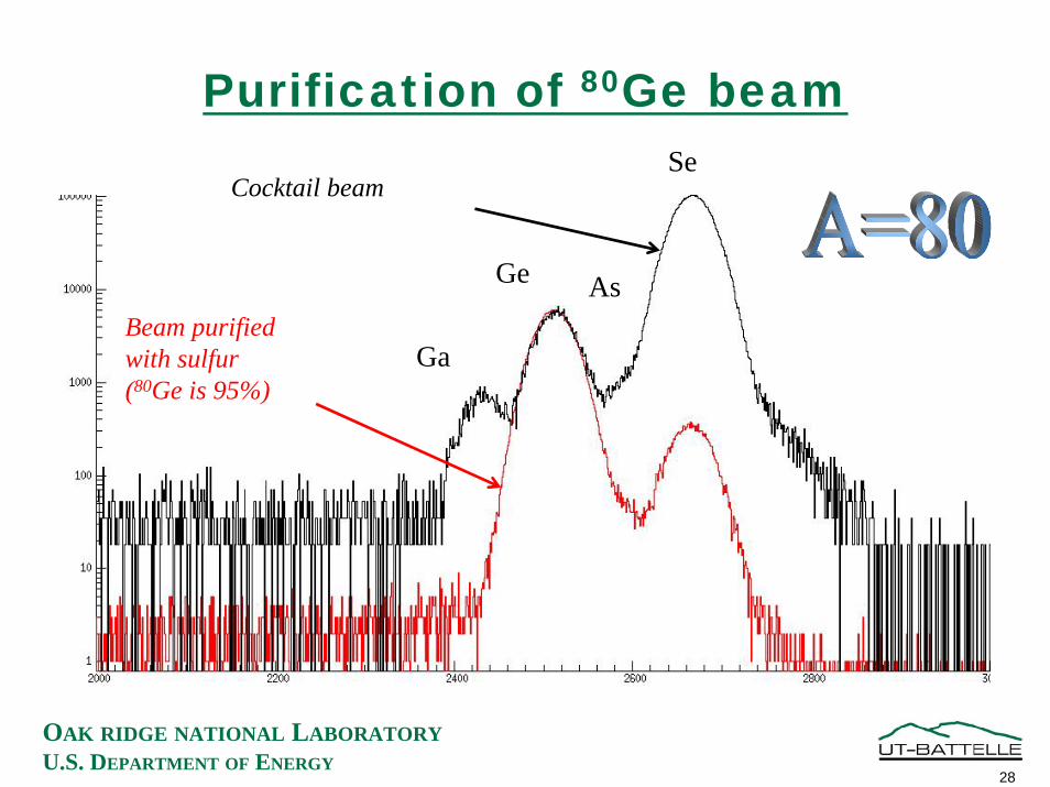
Purification of 80Ge beam
Ga
Ge As
SeCocktail beam
Beam purifiedwith sulfur(80Ge is 95%)
28
OAK RIDGE NATIONAL LABORATORYU.S. DEPARTMENT OF ENERGY
Elevation View of HPTL
29
OAK RIDGE NATIONAL LABORATORYU.S. DEPARTMENT OF ENERGY
RIB Analysis Beam Line
Object Slits& Diagnostics Image Slits
& Diagnostics
Target/Ion Source
Quad 2
Quad 1
Beam Diagnostics
90° Magnet
Diagnostic End Station
30
OAK RIDGE NATIONAL LABORATORYU.S. DEPARTMENT OF ENERGY
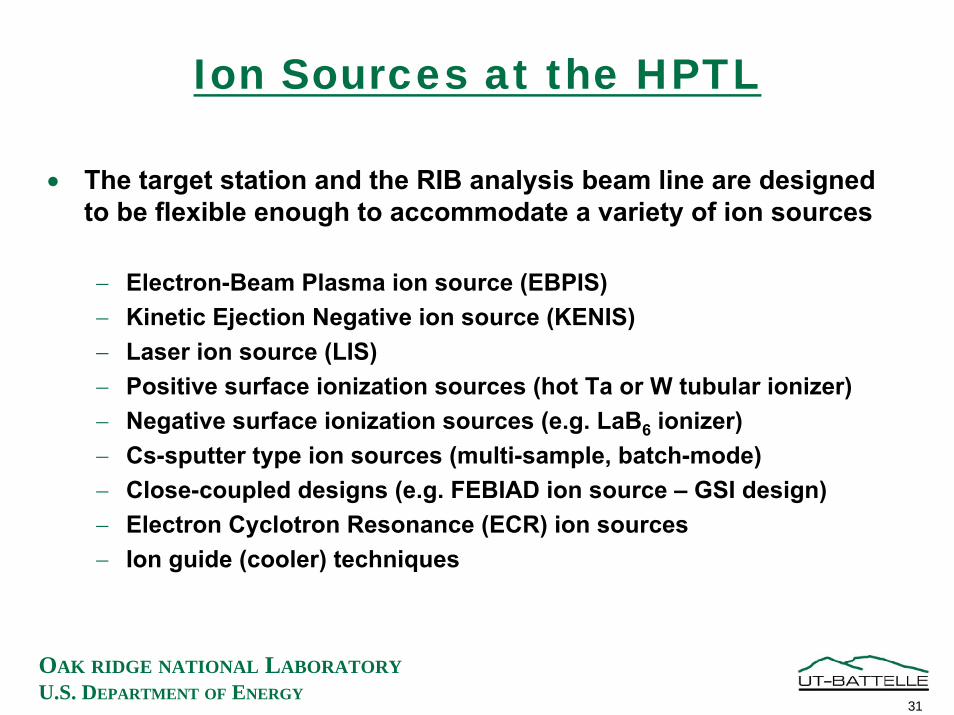
Ion Sources at the HPTL
• The target station and the RIB analysis beam line are designed to be flexible enough to accommodate a variety of ion sources
− Electron-Beam Plasma ion source (EBPIS)− Kinetic Ejection Negative ion source (KENIS)− Laser ion source (LIS)− Positive surface ionization sources (hot Ta or W tubular ionizer)− Negative surface ionization sources (e.g. LaB6 ionizer)− Cs-sputter type ion sources (multi-sample, batch-mode)− Close-coupled designs (e.g. FEBIAD ion source – GSI design)− Electron Cyclotron Resonance (ECR) ion sources− Ion guide (cooler) techniques
31
OAK RIDGE NATIONAL LABORATORYU.S. DEPARTMENT OF ENERGY
Plans for Target Development at the HPTL
• Materials tests with high power (54 MeV protons, up to 20 µA)− SiC, M5Si3 (M = Zr, Ta, W, Nb, …) for 25Al and 26mAl beams− CeS for 33Cl and 34Cl beams
• UC target tests− Proton-induced fission vs. deuteron-induced fission (direct)− Investigate 2-step targets (larger volumes)− Higher density UC targets
• Measure release efficiency for short-lived isotopes• Lifetime of target with high power density
• Thin target geometries− Liquid targets
• As and Se from liquid germanium• Cu from liquid nickel
− Irradiation with 3He and 4He beams (Al2O3 → P, SiC → S, C → 15O)• Production beam manipulation (rastering)
− HfO2 target for increased 17F beam intensity• Ion sources
− LaB6 ion source to make pure Br and I beams (investigate long-term poisoning with high intensity production beams)
− Close-coupled target to reduce effusion times
32
OAK RIDGE NATIONAL LABORATORYU.S. DEPARTMENT OF ENERGY