T1 Post. Inf.- S1 Post. Inf. 0 mm 19.7 mm 19.7 mmARA = Absolute Rotational Angle of MeasurementDirection of measured displacements are indicated using the right-hand Cartesian coordinate system method in biomechanics. Consequently a "-"negative sign preceding a measured value indicates posterior translation for linear movements; and a "-" preceding angular measurements indicaterelative segmental or global extension rotational movement.
Tip of the Dens offset to Sella Turcica n/a 8.4 mm n/a
Sella Turcica horiz.offset to Manubrium n/a 48.0 mm n/a
C0-C1 Chamberlain's to APL n/a 10.4º n/a
C2 Pos. body of C2 relative to APL n/a 58.6º n/a
T1 Centroid horiz offset to manubrium n/a 53.1 mm n/a
T1 Centroid vertical offset to manubrium n/a 41.8 mm n/a
T1 Endplate line to horizontal n/a 16.4º n/a
Thoracic Inlet Incidence Angle n/a 62.2º n/aAPL = Atlas Plane LineDirection of measured displacements are indicated using the right-hand Cartesian coordinate system method in biomechanics. Consequently a "-"negative sign preceding a measured value indicates posterior translation for linear movements; and a "-" preceding angular measurements indicaterelative segmental or global extension rotational movement.
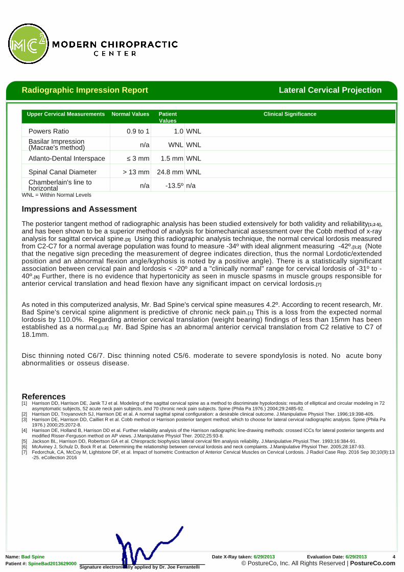
Upper Cervical Measurements Normal Values PatientValues
Clinical Significance
Powers Ratio 0.9 to 1 1.0 WNL
Basilar Impression(Macrae's method) n/a WNL WNL
Atlanto-Dental Interspace ≤ 3 mm 1.5 mm WNL
Spinal Canal Diameter > 13 mm 24.8 mm WNL
Chamberlain's line tohorizontal n/a -13.5º n/a
WNL = Within Normal Levels
Impressions and Assessment
The posterior tangent method of radiographic analysis has been studied extensively for both validity and reliability[1;2-5],and has been shown to be a superior method of analysis for biomechanical assessment over the Cobb method of x-rayanalysis for sagittal cervical spine.[3] Using this radiographic analysis technique, the normal cervical lordosis measuredfrom C2-C7 for a normal average population was found to measure -34º with ideal alignment measuring -42º.[1;2] (Notethat the negative sign preceding the measurement of degree indicates direction, thus the normal Lordotic/extendedposition and an abnormal flexion angle/kyphosis is noted by a positive angle). There is a statistically significantassociation between cervical pain and lordosis < -20º and a "clinically normal" range for cervical lordosis of -31º to -40º.[6] Further, there is no evidence that hypertonicity as seen in muscle spasms in muscle groups responsible foranterior cervical translation and head flexion have any significant impact on cervical lordosis.[7]
As noted in this computerized analysis, Mr. Bad Spine's cervical spine measures 4.2º. According to recent research, Mr.Bad Spine's cervical spine alignment is predictive of chronic neck pain.[1] This is a loss from the expected normallordosis by 110.0%. Regarding anterior cervical translation (weight bearing) findings of less than 15mm has beenestablished as a normal.[1;2] Mr. Bad Spine has an abnormal anterior cervical translation from C2 relative to C7 of18.1mm.
Disc thinning noted C6/7. Disc thinning noted C5/6. moderate to severe spondylosis is noted. No acute bonyabnormalities or osseus disease.
References[1] Harrison DD, Harrison DE, Janik TJ et al. Modeling of the sagittal cervical spine as a method to discriminate hypolordosis: results of elliptical and circular modeling in 72
asymptomatic subjects, 52 acute neck pain subjects, and 70 chronic neck pain subjects. Spine (Phila Pa 1976.) 2004;29:2485-92.[2] Harrison DD, Troyanovich SJ, Harrison DE et al. A normal sagittal spinal configuration: a desirable clinical outcome. J.Manipulative Physiol Ther. 1996;19:398-405.[3] Harrison DE, Harrison DD, Cailliet R et al. Cobb method or Harrison posterior tangent method: which to choose for lateral cervical radiographic analysis. Spine (Phila Pa
1976.) 2000;25:2072-8.[4] Harrison DE, Holland B, Harrison DD et al. Further reliability analysis of the Harrison radiographic line-drawing methods: crossed ICCs for lateral posterior tangents and
modified Risser-Ferguson method on AP views. J.Manipulative Physiol Ther. 2002;25:93-8.[5] Jackson BL, Harrison DD, Robertson GA et al. Chiropractic biophysics lateral cervical film analysis reliability. J.Manipulative.Physiol.Ther. 1993;16:384-91.[6] McAviney J, Schulz D, Bock R et al. Determining the relationship between cervical lordosis and neck complaints. J.Manipulative Physiol Ther. 2005;28:187-93.[7] Fedorchuk, CA, McCoy M, Lightstone DF, et al. Impact of Isometric Contraction of Anterior Cervical Muscles on Cervical Lordosis. J Radiol Case Rep. 2016 Sep 30;10(9):13
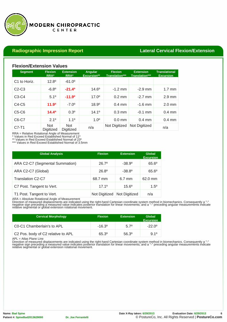
RRA = Relative Rotational Angle of Measurement* Values in Red Exceed Established Normal of 11º** Values in Red Exceed Established Normal of 23º*** Values in Red Exceed Established Normal of 3.5mm
Global Analysis Flexion Extension GlobalExcursion
ARA C2-C7 (Segmental Summation) 26.7º -38.9º 65.6º
ARA C2-C7 (Global) 26.8º -38.8º 65.6º
Translation C2-C7 68.7 mm 6.7 mm 62.0 mm
C7 Post. Tangent to Vert. 17.1º 15.6º 1.5º
T1 Post. Tangent to Vert. Not Digitized Not Digitized n/aARA = Absolute Rotational Angle of MeasurementDirection of measured displacements are indicated using the right-hand Cartesian coordinate system method in biomechanics. Consequently a "-"negative sign preceding a measured value indicates posterior translation for linear movements; and a "-" preceding angular measurements indicaterelative segmental or global extension rotational movement.
C2 Pos. body of C2 relative to APL 65.3º 56.3º 9.1ºAPL = Atlas Plane LineDirection of measured displacements are indicated using the right-hand Cartesian coordinate system method in biomechanics. Consequently a "-"negative sign preceding a measured value indicates posterior translation for linear movements; and a "-" preceding angular measurements indicaterelative segmental or global extension rotational movement.
The posterior tangent method of radiographic analysis has been studied extensively for both validity and reliability[4-8],
and has been shown to be a superior method of analysis for biomechanical assessment over the Cobb method of x-ray
analysis for sagittal cervical spine.[6] Normal values for intersegmental motion should not exceed more than 10-11º of
angular motion.[9] Using the posterior tangent method of radiographic analysis, motion that exceeds 10º has been
shown to predict and discriminate minor ligamentous injuries from those patients with true whiplash type ligamentous
injuries.[3] Corroborating these findings using another method of analysis (inferior endplate assessment), an alteration
of motion segment integrity (AOMSI) has been defined as motion at the level in question that is more than 11º greater
than at either adjacent level.[1] Regarding segmental translational movements, authors have noted that subluxation
should be noted with a range of 1.0-3.0mm[2] of intersegmental movement with absolute clinical cutoff threshold value of
3.5mm.[1;9] Of additional importance, improvement in neutral lateral cervical lordosis has been shown to be associated
with significant improvement in the translational and rotational motions of the lower cervical spine. Flexion/extension
kinematics are partially dependent on the posture and sagittal curve orientation.[10]
There is possible significant damage to the posterior longitudinal ligament and/or posterior intervertebral disc and/or
interspinous ligament which is indicated by an increased widening of the posterior intervertebral disc space angulation
and increased separation of spinous processes at the following levels: C4-C5, C5-C6.
There is anterior widening of the intervertebral disc space at C2-C3, C3-C4 levels evidenced by excessive segmental
extension, which indicates possible damage to the anterior longitudinal ligament and/or intervertebral disc at said level.
Segmental flexion instability is noted at the following segments: C4-C5 of 11.9º, C5-C6 of 14.4º.
Segmental extension instability is noted at the following segments: C2-C3 of -21.4º, C3-C4 of -11.9º.
Segmental angular excursion instability is noted at the following segments: none
Segmental subluxation for flexion is noted at the following segments: C2-C3 with -1.2 mm.
Segmental subluxation for extension is noted at the following segments: C2-C3 with -2.9 mm, C3-C4 with -2.7 mm,
C4-C5 with -1.6 mm.
Segmental translational instability for flexion is noted at the following segments: none
Segmental translational instability for extension is noted at the following segments: none
Flexion View Impressions: Very limited global ROM is noted with associated spinal coupling. No acute bonyabnormalities or osseus disease.
Extension View Impressions: Very limited global ROM is noted with associated spinal coupling most noted mid tolower cervical spine. I suspect delayed instability will appear once more normal global ROM is achieved.
References[1] Guides to the Evaluation of Permanent Impairment, Fifth Edition.American Medical Association, 2000.[2] Green JD, Harle TS, Harris JH, Jr. Anterior subluxation of the cervical spine: hyperflexion sprain. AJNR Am.J.Neuroradiol. 1981;2:243-50.[3] Griffiths HJ, Olson PN, Everson LI et al. Hyperextension strain or "whiplash" injuries to the cervical spine. Skeletal Radiol. 1995;24:263-6.[4] Harrison DD, Harrison DE, Janik TJ et al. Modeling of the sagittal cervical spine as a method to discriminate hypolordosis: results of elliptical and circular modeling in 72
asymptomatic subjects, 52 acute neck pain subjects, and 70 chronic neck pain subjects. Spine (Phila Pa 1976.) 2004;29:2485-92.[5] Harrison DD, Troyanovich SJ, Harrison DE et al. A normal sagittal spinal configuration: a desirable clinical outcome. J.Manipulative Physiol Ther. 1996;19:398-405.[6] Harrison DE, Harrison DD, Cailliet R et al. Cobb method or Harrison posterior tangent method: which to choose for lateral cervical radiographic analysis. Spine (Phila Pa
1976.) 2000;25:2072-8.[7] Harrison DE, Holland B, Harrison DD et al. Further reliability analysis of the Harrison radiographic line-drawing methods: crossed ICCs for lateral posterior tangents and
modified Risser-Ferguson method on AP views. J.Manipulative Physiol Ther. 2002;25:93-8.[8] Jackson BL, Harrison DD, Robertson GA et al. Chiropractic biophysics lateral cervical film analysis reliability. J.Manipulative.Physiol.Ther. 1993;16:384-91.[9] White AA, III, Johnson RM, Panjabi MM et al. Biomechanical analysis of clinical stability in the cervical spine. Clin.Orthop. 1975;85-96.[10] Moustafa IM, et al. Does rehabilitation of cervical lordosis influence sagittal cervical spine flexion extension kinematics in cervical spondylotic radiculopathy subjects? J Back
Musculoskelet Rehabil. 2016 Mar 27. doi: 10.3233/BMR-150464.
Signature electronically applied by Dr. Joe Ferrantelli
Radiographic Impression Report AP Open Mouth
Name: Bad Spine X-Ray was obtained: 6/29/2013 Date of Digitization: 6/29/2013Date of Birth: 8/7/1954
Mr. Bad Spine’s x-rays were analyzed utilizing the PostureRay® computerized X-ray digitizing system with impressions interpreted by Dr. Joe
Ferrantelli. X-Ray digitization for spinal biomechanics has been shown to be valid when compared to standard hand drawn methods. The patient’s
findings were then compared to established normals at each level and then globally. The X-Ray mensuration method used in analyzing this patient
have been studied for reliability and validity and these results are as follows:
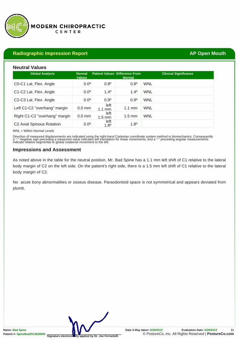
Right Left
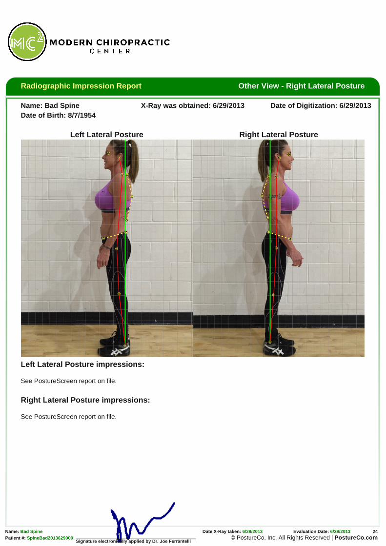
The horizontal green line represents the normal atlas position. The vertical green line is a plumb line, also indicatingnormal vertical spinal alignment.
The horizontal red line represents the patient’s Atlas vertebrae position. Ideally this should superimpose the greennormal horizontal line. The red vertically oriented line should superimpose the true green vertical plumb line in spineswith normal alignment.
Direction of measured displacements are indicated using the right-hand Cartesian coordinate system method in biomechanics. Consequentlya "-" negative sign preceding a measured value indicates left translation for linear movements; and a "-" preceding angular measurementsindicate relative segmental or global rotational movement to the left.
Impressions and Assessment
As noted above in the table for the neutral position, Mr. Bad Spine has a 1.1 mm left shift of C1 relative to the lateral
body margin of C2 on the left side. On the patient's right side, there is a 1.5 mm left shift of C1 relative to the lateral
Signature electronically applied by Dr. Joe Ferrantelli
No acute bony abnormalities or osseus disease. Paraodontoid space is not symmetrical and appears deviated from
plumb.
Radiographic Impression Report AP Cervical Projection
Name: Bad Spine X-Ray was obtained: 6/29/2013 Date of Digitization: 6/29/2013Date of Birth: 8/7/1954
Mr. Bad Spine’s x-rays were analyzed utilizing the PostureRay® computerized X-ray digitizing system with impressions interpreted by Dr. Joe
Ferrantelli. X-Ray digitization for spinal biomechanics has been shown to be valid when compared to standard hand drawn methods. The patient’s
findings were then compared to established normals at each level and then globally. The X-Ray mensuration method used in analyzing this patient
have been studied for reliability and validity and these results are as follows:
Right Left
This green line represents normal spinal position.
This red line represents the patient’s alignment and theprojected centers of mass of the spine.
Spinal Biomechanics Compared to Normal
Global Analysis Normal Values Patient Values Difference FromNormal
RZA T5 0º -3.3º 3.3º
CDA C2-T5 0º 0.8º 0.8º
Translation C2-T5 0 mm 9.8 mm 9.8 mm
CDA = Cervico-dorsal Angle and is a measure of the mid cervical angleRZA = Rotation Angle relative to true vertical of the lower cervical and upperthoracic spine
Impressions and Assessment
The x-ray analysis performed on this AP cervico-thoracic view has
been studied for reliability and demonstrated both intraexaminaer
and interexaminer reliability.[1] As noted above in the table, Mr. Bad
Spine’s cervical spine is translated (listed) from plumb by 9.8 mm to
the left. Of importance is that the patient has a mid neck abnormal
angle of 0.8 degrees to the right. The patient has an angular
displacement from normal (plumb) of the lower cervical and upper
thoracic spine of 3.3 degrees to the left.
No acute bony abnormalities or osseus disease. Mild to moderate
diffuse degenerative changes noted.
References[1] Troyanovich SJ, Harrison DE, et al. Chiropractic Biophysics Digitized Radiographic Mensuration Analysis of the Anteroposterior Cervicothoracic View: A Reliability Study.
Name: Bad Spine X-Ray was obtained: 6/29/2013 Date of Digitization: 6/29/2013Date of Birth: 8/7/1954
Mr. Bad Spine’s x-rays were analyzed utilizing the PostureRay® computerized X-ray digitizing system with impressions interpreted by Dr. Joe
Ferrantelli. X-Ray digitization for spinal biomechanics has been shown to be valid when compared to standard hand drawn methods. The patient’s
findings were then compared to established normals at each level and then globally. The X-Ray mensuration method used in analyzing this patient
have been studied for reliability and validity and these results are as follows:
Anterior Posterior
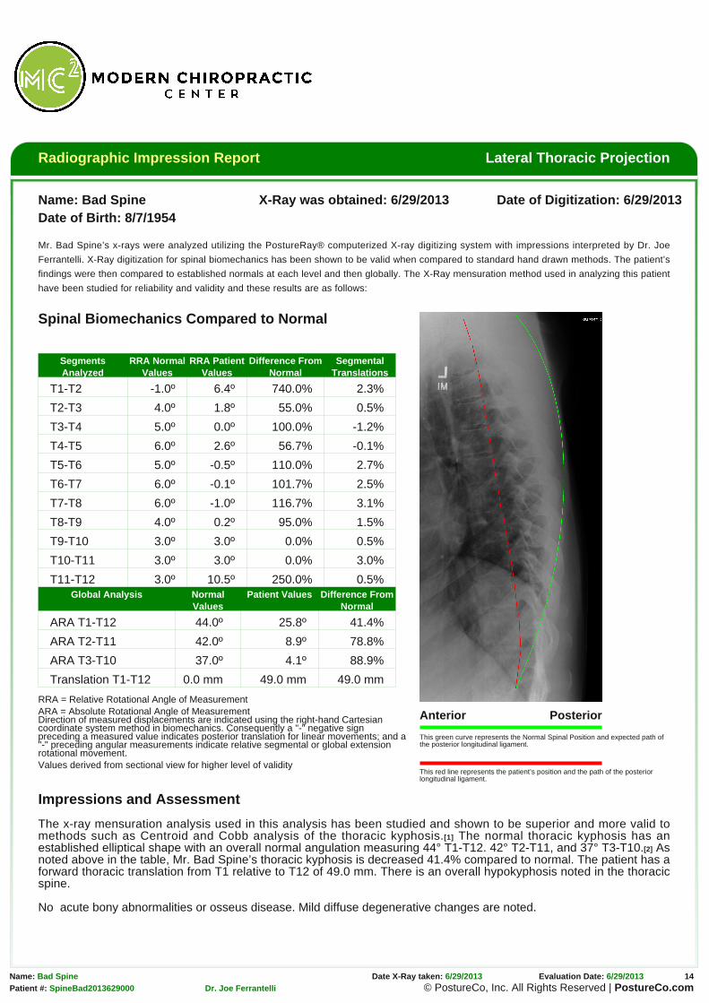
This green curve represents the Normal Spinal Position and expected path ofthe posterior longitudinal ligament.
This red line represents the patient’s position and the path of the posteriorlongitudinal ligament.
Spinal Biomechanics Compared to Normal
SegmentsAnalyzed
RRA NormalValues
RRA PatientValues
Difference FromNormal
SegmentalTranslations
T1-T2 -1.0º 6.4º 740.0% 2.3%
T2-T3 4.0º 1.8º 55.0% 0.5%
T3-T4 5.0º 0.0º 100.0% -1.2%
T4-T5 6.0º 2.6º 56.7% -0.1%
T5-T6 5.0º -0.5º 110.0% 2.7%
T6-T7 6.0º -0.1º 101.7% 2.5%
T7-T8 6.0º -1.0º 116.7% 3.1%
T8-T9 4.0º 0.2º 95.0% 1.5%
T9-T10 3.0º 3.0º 0.0% 0.5%
T10-T11 3.0º 3.0º 0.0% 3.0%
T11-T12 3.0º 10.5º 250.0% 0.5%Global Analysis Normal
ValuesPatient Values Difference From
Normal
ARA T1-T12 44.0º 25.8º 41.4%
ARA T2-T11 42.0º 8.9º 78.8%
ARA T3-T10 37.0º 4.1º 88.9%
Translation T1-T12 0.0 mm 49.0 mm 49.0 mm
RRA = Relative Rotational Angle of MeasurementARA = Absolute Rotational Angle of MeasurementDirection of measured displacements are indicated using the right-hand Cartesiancoordinate system method in biomechanics. Consequently a "-" negative signpreceding a measured value indicates posterior translation for linear movements; and a"-" preceding angular measurements indicate relative segmental or global extensionrotational movement.Values derived from sectional view for higher level of validity
Impressions and Assessment
The x-ray mensuration analysis used in this analysis has been studied and shown to be superior and more valid tomethods such as Centroid and Cobb analysis of the thoracic kyphosis.[1] The normal thoracic kyphosis has anestablished elliptical shape with an overall normal angulation measuring 44° T1-T12. 42° T2-T11, and 37° T3-T10.[2] Asnoted above in the table, Mr. Bad Spine’s thoracic kyphosis is decreased 41.4% compared to normal. The patient has aforward thoracic translation from T1 relative to T12 of 49.0 mm. There is an overall hypokyphosis noted in the thoracicspine.
No acute bony abnormalities or osseus disease. Mild diffuse degenerative changes are noted.
References[1] Harrison DE, Cailliet R, Harrison DD et al. Reliability of Centroid, Cobb, and Harrison Posterior Tangent Methods: Which to Choose for Analysis of Thoracic Kyphosis JMPT
2000 Sep Vol. 23, Num 7: 476-482.[2] Harrison DE, Janik T, Harrison DD, et al. Can the Thoracic Kyphosis be Modeled with a Simple Geometric Shape? The Results of Circular and Elliptical Modeling in 80
Signature electronically applied by Dr. Joe Ferrantelli
Radiographic Impression Report AP Thoracic Scoliosis Projection
Name: Bad Spine X-Ray was obtained: 6/29/2013 Date of Digitization: 6/29/2013Date of Birth: 8/7/1954
Mr. Bad Spine’s x-rays were analyzed utilizing the PostureRay® computerized X-ray digitizing system with impressions interpreted by Dr. Joe
Ferrantelli. X-Ray digitization for spinal biomechanics has been shown to be valid when compared to standard hand drawn methods. The patient’s
findings were then compared to established normals at each level and then globally. The X-Ray mensuration method used in analyzing this patient
have been studied for reliability and validity and these results are as follows:
Right Left
This green line represents normal spinal position.
This red line represents the patient’s alignment and the projected centers of mass of the spine.R-F: Risser-Ferguson Method of analysisCobb: Cobb Method of analysis
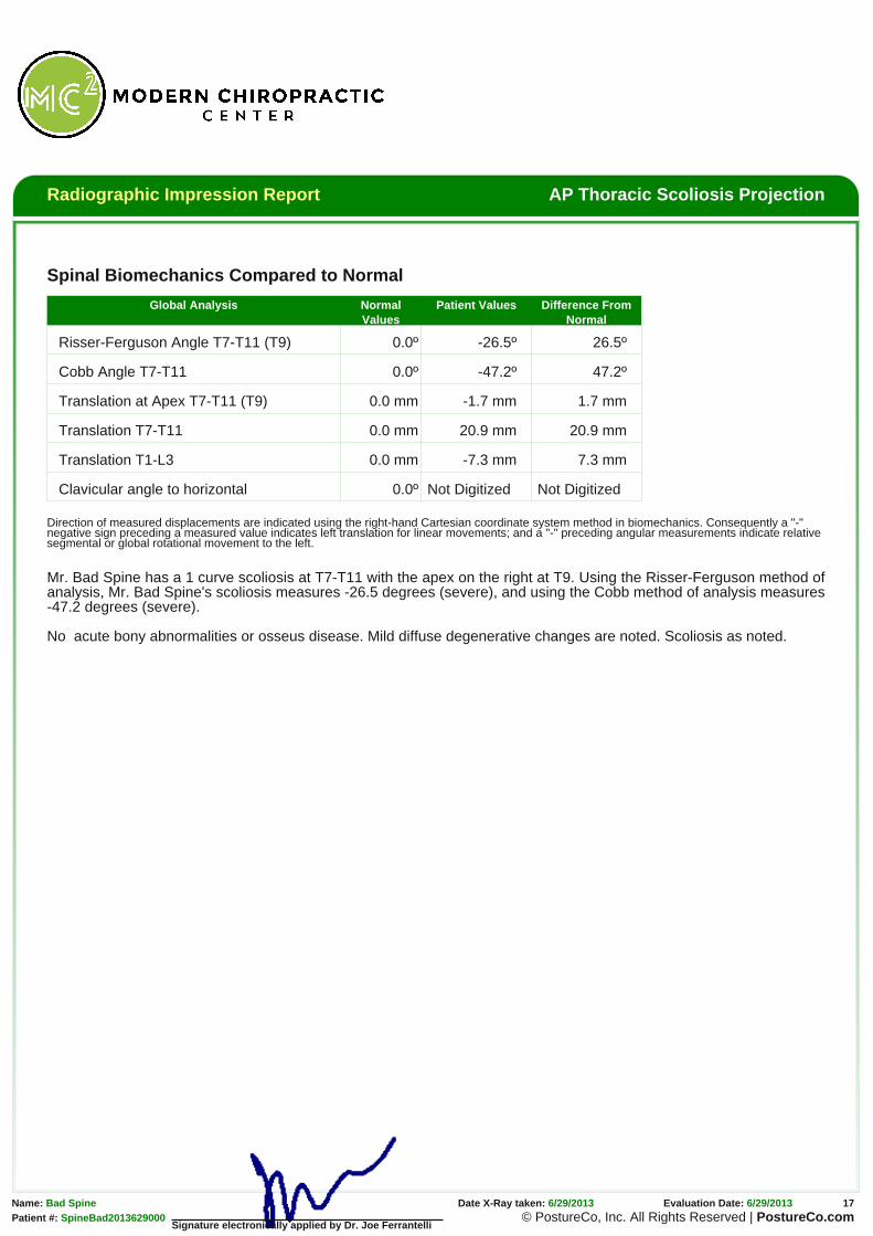
Translation at Apex T7-T11 (T9) 0.0 mm -1.7 mm 1.7 mm
Translation T7-T11 0.0 mm 20.9 mm 20.9 mm
Translation T1-L3 0.0 mm -7.3 mm 7.3 mm
Clavicular angle to horizontal 0.0º Not Digitized Not Digitized
Direction of measured displacements are indicated using the right-hand Cartesian coordinate system method in biomechanics. Consequently a "-"negative sign preceding a measured value indicates left translation for linear movements; and a "-" preceding angular measurements indicate relativesegmental or global rotational movement to the left.
Mr. Bad Spine has a 1 curve scoliosis at T7-T11 with the apex on the right at T9. Using the Risser-Ferguson method ofanalysis, Mr. Bad Spine's scoliosis measures -26.5 degrees (severe), and using the Cobb method of analysis measures-47.2 degrees (severe).
Name: Bad Spine X-Ray was obtained: 6/29/2013 Date of Digitization: 6/29/2013Date of Birth: 8/7/1954
Mr. Bad Spine’s x-rays were analyzed utilizing the PostureRay® computerized X-ray digitizing system with impressions interpreted by Dr. Joe
Ferrantelli. X-Ray digitization for spinal biomechanics has been shown to be valid when compared to standard hand drawn methods. The patient’s
findings were then compared to established normals at each level and then globally. The X-Ray mensuration method used in analyzing this patient
have been studied for reliability and validity and these results are as follows:
Anterior Posterior
This green line represents the Normal Spinal Position and expected path of theposterior longitudinal ligament.
This red line represents the patient’s position and the path of the posteriorlongitudinal ligament.
Spinal Biomechanics Compared to Normal
SegmentsAnalyzed
RRA NormalValues
RRA PatientValues
Difference FromNormal
SegmentalTranslations
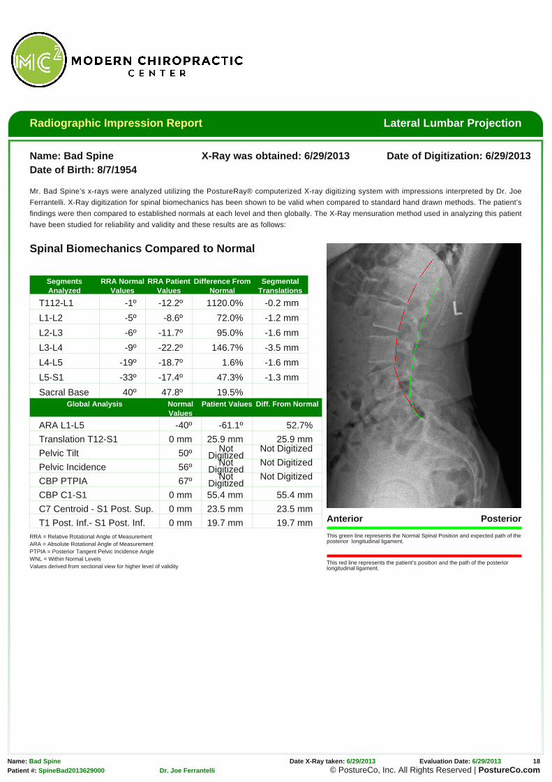
T112-L1 -1º -12.2º 1120.0% -0.2 mm
L1-L2 -5º -8.6º 72.0% -1.2 mm
L2-L3 -6º -11.7º 95.0% -1.6 mm
L3-L4 -9º -22.2º 146.7% -3.5 mm
L4-L5 -19º -18.7º 1.6% -1.6 mm
L5-S1 -33º -17.4º 47.3% -1.3 mm
Sacral Base 40º 47.8º 19.5%Global Analysis Normal
ValuesPatient Values Diff. From Normal
ARA L1-L5 -40º -61.1º 52.7%
Translation T12-S1 0 mm 25.9 mm 25.9 mm
Pelvic Tilt 50º NotDigitized
Not Digitized
Pelvic Incidence 56º NotDigitized
Not Digitized
CBP PTPIA 67º NotDigitized
Not Digitized
CBP C1-S1 0 mm 55.4 mm 55.4 mm
C7 Centroid - S1 Post. Sup. 0 mm 23.5 mm 23.5 mm
T1 Post. Inf.- S1 Post. Inf. 0 mm 19.7 mm 19.7 mmRRA = Relative Rotational Angle of MeasurementARA = Absolute Rotational Angle of MeasurementPTPIA = Posterior Tangent Pelvic Incidence AngleWNL = Within Normal LevelsValues derived from sectional view for higher level of validity
The x-ray mensuration utilized in this assessment has been studied and noted to have high inter- and intra-examiner
reliability[1] and also to be preferred method of analysis when compared to Cobb and Centroid, and Trall analysis
especially when the angle of lordosis is to be measured.[2] Normal lordosis for the lumbar spine has been demonstrated
and for individuals with normal morphology, it has been found that those with a hyperlordosis were associated with
acute lumbar pain, compared to those with chronic lumbar pain demonstrating a hypolordosis. Thus altered
configurations of the normal elliptical anthropometric model of the lumbar lordosis may clinically correlate with the
development of degenerative changes in the spinal tissues and production of low back pain syndromes.[3]
As noted above in the table, Mr. Bad Spine has an overall increase from normal lordosis by 52.8%. The patient has a
anterior translation from T12 relative to S1 of 25.9 mm.
No acute bony abnormalities or osseus disease.
References[1] Troyanovich SJ, Robertson GA, Harrison DD, Holland B. Intra- and interexaminer reliability of the chiropractic biophysics lateral lumbar radiographic mensuration procedure.
J Manipulative Physiol Ther. 1995 Oct;18(8):519-24.[2] Harrison DE, Harrison DD, et al. Radiographic Analysis of Lumbar Lordosis, Centroid, Cobb, TRALL, and Harrison Posterior Tangent Methods. Spine (Phila Pa 1976). 2001
Jun 1;26(11):E235-42.[3] (3)Harrison DD, Cailliet R et al. Elliptical modeling of the sagittal lumbar lordosis and segmental rotation angles as a method to discriminate between normal and low back
Signature electronically applied by Dr. Joe Ferrantelli
Radiographic Impression Report AP Lumbar Scoliosis Projection
Name: Bad Spine X-Ray was obtained: 6/29/2013 Date of Digitization: 6/29/2013Date of Birth: 8/7/1954
Mr. Bad Spine’s x-rays were analyzed utilizing the PostureRay® computerized X-ray digitizing system with impressions interpreted by Dr. Joe
Ferrantelli. X-Ray digitization for spinal biomechanics has been shown to be valid when compared to standard hand drawn methods. The patient’s
findings were then compared to established normals at each level and then globally. The X-Ray mensuration method used in analyzing this patient
have been studied for reliability and validity and these results are as follows:
Right Left
This green line represents normal spinal position.
This red line represents the patient’s alignment and the projected centers of mass of the spine.R-F: Risser-Ferguson Method of analysisCobb: Cobb Method of analysis
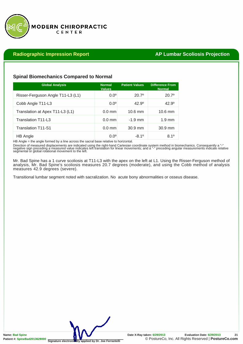
Translation at Apex T11-L3 (L1) 0.0 mm 10.6 mm 10.6 mm
Translation T11-L3 0.0 mm -1.9 mm 1.9 mm
Translation T11-S1 0.0 mm 30.9 mm 30.9 mm
HB Angle 0.0º -8.1º 8.1ºHB Angle = the angle formed by a line across the sacral base relative to horizontal.Direction of measured displacements are indicated using the right-hand Cartesian coordinate system method in biomechanics. Consequently a "-"negative sign preceding a measured value indicates left translation for linear movements; and a "-" preceding angular measurements indicate relativesegmental or global rotational movement to the left.
Mr. Bad Spine has a 1 curve scoliosis at T11-L3 with the apex on the left at L1. Using the Risser-Ferguson method ofanalysis, Mr. Bad Spine's scoliosis measures 20.7 degrees (moderate), and using the Cobb method of analysismeasures 42.9 degrees (severe).
Signature electronically applied by Dr. Joe Ferrantelli
Transitional lumbar segment noted with sacralization. No acute bony abnormalities or osseus disease.
Radiographic Impression Report AP Modified Ferguson View(Sacral Base)
Name: Bad Spine X-Ray was obtained: 6/29/2013 Date of Digitization: 6/29/2013Date of Birth: 8/7/1954
Mr. Bad Spine’s x-rays were analyzed utilizing the PostureRay® computerized X-ray digitizing system with impressions interpreted by Dr. Joe
Ferrantelli. X-Ray digitization for spinal biomechanics has been shown to be valid when compared to standard hand drawn methods. The patient’s
findings were then compared to established normals at each level and then globally. The X-Ray mensuration method used in analyzing this patient
have been studied for reliability and validity and these results are as follows:
Right Left
This green line represents normal spinal position.
This red line represents the patient’s alignment and theprojected centers of mass of the spine.
Spinal Biomechanics Compared to Normal
Global Analysis NormalValues
Patient Values Difference FromNormal
Femur Unleveling* 0 mmright
2.8 mm 2.8 mm
Sacral Base Unleveling* 0 mmleft
10.5 mm 10.5 mm
Pubic Symphysis to S2 0 mmright
-3.0 mm 3.0 mm
HB Angle 0º -3.4º 3.4º
LS Angle T12-L5 (L2 apex) 90º -89.1º 0.9º
LD Angle T12-L5 0º 8.4º 8.4º
Translation T12-S1 0 mm 5.6 mm 5.6 mm
* Accounting for magnificationHB Angle = the angle formed by a line across the sacral base relative to horizontal.LS Angle = Lumbo-sacral angleLD Angle = Lumbar-Dorsal angle
Impressions and Assessment
As noted above in the table, the left side of the sacrum is deficientby 14.1mm accounting for magnification, it measures 10.5mm. TheFemur offset is 3.7mm short on the right side which approximates2.8mm, when accounting for magnification. As for the PubicSymphysis offset to S2, it measures -3.0mm to the right.
There are sufficient visible vertebrae to measure that Mr. BadSpine’s upper lumbar spine is translated (listed) from plumb by 5.6mm to the left. The patient has a mid lumbar curve of 8.4 degrees.The patient’s sacral base is offset and inferior on the left.