—Radiometrics, Inc. STAR FIELD SIMULATOR FINAL REPORT A02/M? 101 October 31, 1985 ric £ , IBC.) 24 03A N86-1S268 Ucclas G3/89 03663 Prepared For George C. Marshall Space Flight Center National Aeronautics and Space Administration Marshall Space Flight Center, Alabama 35812 1 2O21 South Memorial Parkway • Huntsville, Alabarna 35£J03 Phone: (205) 881-1272 • 881-1273
Transcript
—Radiometrics, Inc.
STAR FIELD SIMULATOR
FINAL REPORT
A02/M? 101
October 31, 1985
ric£, IBC.) 24
03A
N86-1S268
UcclasG3/89 03663
Prepared ForGeorge C. Marshall Space Flight Center
National Aeronautics and Space AdministrationMarshall Space Flight Center, Alabama 35812
1 2O21 South Memorial Parkway • Huntsville, Alabarna 35£J03
Phone: (205) 881-1272 • 881-1273
STAR FIELD SIMULATOR
FINAL REPORT
Contract No.
NAS8-35830
October 31, 1985
Prepared For
George C. Marshall Space Flight CenterNational Aeronautics and Space AdministrationMarshall Space Flight Center, Alabama 35812
ByRadiometrics, Inc.
12021 South Memorial ParkwayHuntsville, Alabama 35803
5 CONCLUSIONS AND RECOMMENDATIONS 176 EQUIPMENT PARTS LIST ' 1 9
LIST OF ILLUSTRATIONS
Figure Title Page
1 Star Field Simulator Control Unit 4
2 Schematic Diagram of Simulator 6
3 Electrical Schematic Diagram 9
4 Photopic Calibration of Radiometer 12
5 Collimator Output Calibration . 14
n
LIST OF TABLES
Table. Title Page
1 Source A Calibration Data 8
2 Source B Calibration Data 8
3 Source C Calibration Data 8
4 Major Component Parts List 18
1 INTRODUCTION
This report.covers the efforts of Radiometrics, Inc. for the
National Aeronautics and Space Administration (NASA) under
Contract Number NAS8-35803 in providing a Star Field Simulator to
serve as a source of radiation for the ASTRO Star Tracker.
1.1- Background
The star tracker and simulator are components of a motion
compensation test facility located at Marshall Space Flight
Center in Huntsville, Alabama. Preflight tests and simulations
using various levels of guide stars will be performed in the test
facility to establish performance of the motion compensation
system before being used in a flight environment.
The ASTRO Star Tracker operates over a wide dynamic range of
irradiance corresponding to visual stellar magnitudes of -0.8 to
8. A minimum of three simulated guide stars with variable
magnitudes are needed to fully test the Star Tracker performance
under simulated mission conditions.
- 1 -
1.2 Objectives
The objectives of this effort were to design and build a star
field simulator that would:
Provide sources of collimated light to simulate natural
guide stars
Provide three simulated stars arranged in a triangular
pattern within the field of view of the tracker with angular
separations of approximately 30 arc seconds
Provide independent magnitude adjustment for each star from
-0.8 to 8 visual magnitude
Provide separate monitors for each simulated star's
brightness that can be calibrated in visual stellar
magnitude
Provide a collimated beam approximately 8 inches in diameter
with a beam divergence of 4 microradian
Have the light sources and collimator mounted in separate
packages with fiber optics cables connecting the sources to
the collimator.
- 2 -
2 DESCRIPTION
2.1 Light Source
The Star Field Simulator has three independent light sources
mounted in an enclosure separated mechanically from the
collimator unit to divide the mass of the equipment and remove
the heating effects from the area of the collimator optics.
Figure 1 is a photograph of the Control Unit. The power supply
and lamps are contained in this package.
Each source consists of a tungsten lamp, color temperature
correcting filter, condenser lens, LCD display and a neutral
density filter wheel. Lamp voltage is varied with a multi-turn
control mounted on the front panel. The electrical control
provides a range of adjustment equivalent to approximately a 10
to 1 change in brightness of the simulated stars. Three neutral
density attenuating filters and one open position are provided by
the manually operated filter wheels. The filter wheels provide
transmittances of 0.001, 0.01, 0.1 and 1. The combined effects of
the electrical adjustment and the attenuating filters produce an
output adjustment corresponding to visual star magnitudes of -0.8
to 8.
- 3 -
Radiometrics, Inc.:
ORIGINAL PAGE 13OF POOR QUALITY
OUTPUTCONTROL (3)
POWERSWITCH
NEUTRAL DENSITYFILTER WHEEL (3)
LIGHT-SOURCEOUTPUT(3)
FIGURE 1. STAR FIELD SIMULATOR CONTROL UNIT
-4-
The lamps, condenser lenses, attenuating filters and displays are
mounted in a common enclosure along with the dc power supply.
The enclosure is light tight to prevent stray light from escaping
into the room.
2.2 Collimator
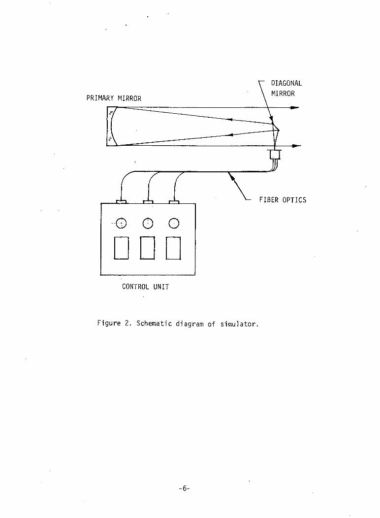
Figure '2 is a schematic diagram of the light source and
collimator optics. The collimator is a Newtonian configuration
with a plane diagonal secondary and an f/6 paraboloid primary.
The simulated stars are pinholes 5 microns in diameter located in
the focal plane of the collimator. One pinhole is on the optical
axis, two more are located off axis to form a triangular
pattern. The angular separation is approximately 30 arc seconds
between pinholes.
2.3 Fiber Optics
Each light source is coupled to the collimator by a fiber optics
cable approximately four feet long. The fiber cable has a single
fused quartz core 50 microns in diameter. The output end of the
fiber is mounted directly behind the pinhole to provide uniform
illumination of the 8-inch primary mirror. The fiber cables are
terminated at the input end with Amphenol screw-on connectors for
convenient attachment to the light source module.
- 5 -
PRIMARY MIRROR
o o o
DIAGONALMIRROR
FIBER OPTICS
CONTROL UNIT
Figure 2. Schematic diagram of simulator.
-6-
2.4 Output Control
Star magnitude adjustment is provided by multi-turn controls
located on the Control Unit. Each lamp has a separate control and
LCD display that permits precise settings of the collimator light
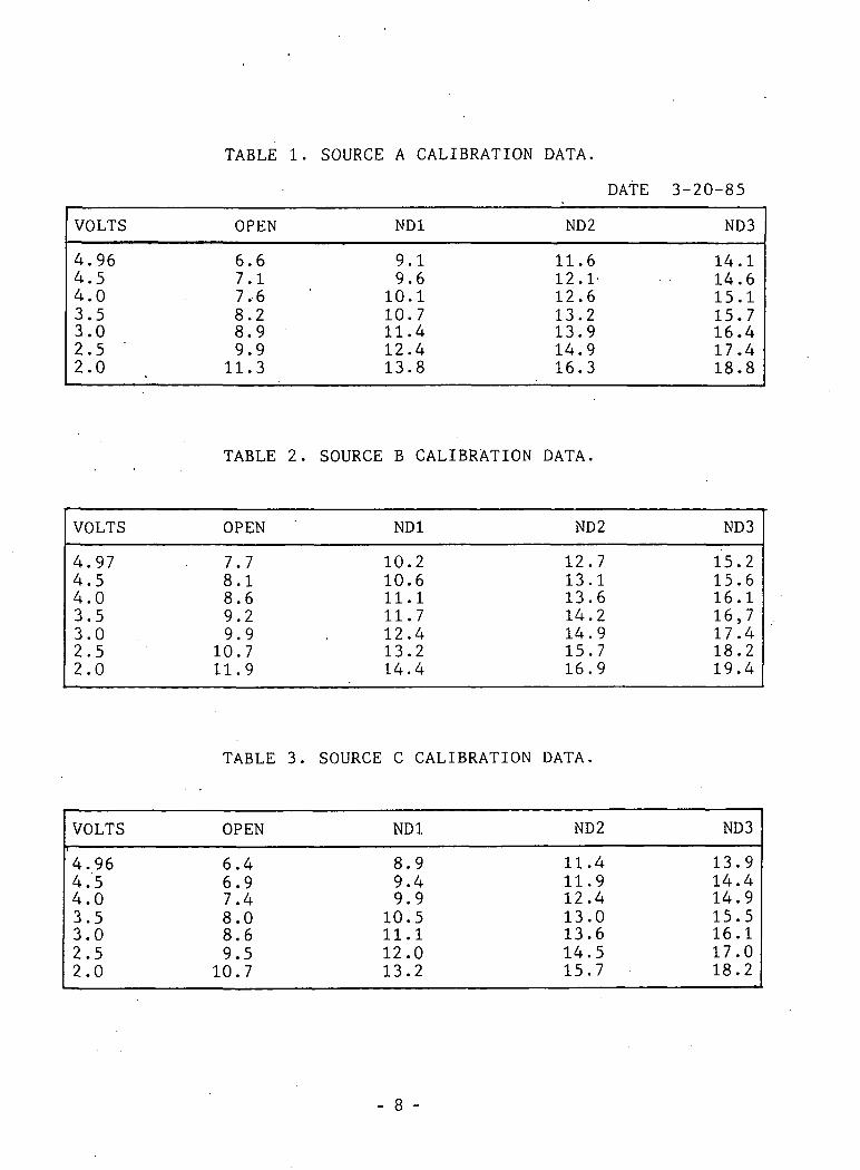
output. Calibration data consisting of simulated star magnitude,
versus display reading is provided with the simulator. Tables 1
through 3 contain the calibration data supplied with the
instrument.
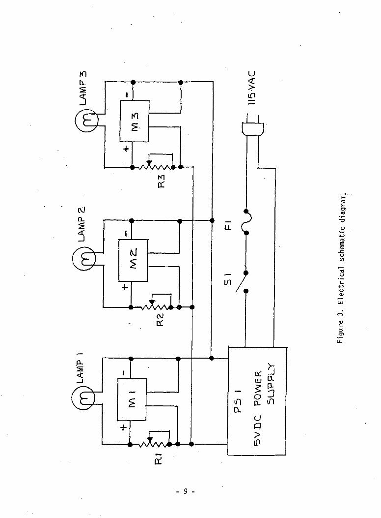
Figure '3 is an electrical schematic of the simulator showing the
lamps, dc power supply, multi-turn controls and the digital
voltmeter modules. All the electrical components are located in
the light source unit.
3 TECHNICAL DISCUSSION '
3.1 Initial Requirements
Initially the Star Field Simulator was designed to produce a
collimated beam of light with an angular divergence of one
milliradian or less. The simulator's objective was an f/2.2
achromat 110 millimeters in diameter. The polished ends of the
fiber optics interconnecting cables were positioned in the focal
plane of the objective lens to provide the simulated star
illumination. The fiber optics cables were single fiber fused
TABLE 1. SOURCE A CALIBRATION DATA.
DATE 3-20-85
VOLTS
4.964.54.03.53.02.52.0
OPEN
6.67.17.68.28.99.911.3
ND1
9.19.610.110.711.412.413.8
ND2
11.612.1-12.613.213.914.916.3
ND3
14.114.615.115.716.417.418.8
TABLE 2. SOURCE B CALIBRATION DATA.
VOLTS
4.974.54.03.53.02.52.0
OPEN
7.78.18.69.29.9
10.711.9
ND1
10.210.611.111.712.413.214.4
ND2
12.713.113.614.214.915.716.9
ND3
15.215.616.116,717.418.219.4
TABLE 3. SOURCE C CALIBRATION DATA.
VOLTS
4.964.54.03.53.02.52.0
OPEN
6.46.97.48.08.69.5
10.7
ND1
8.99.49.9
10.511.112.013.2
ND2
11.411.912.413.013.614.515.7
ND3
13.914.414.915.516.117.018.2
- 8 -
S_cn
-oo
O
roO
<JO)
CO
OJ
- 9 -
quartz cores 50 microns in diameter. The core diameter and the
objective lens produced a theoretical beam divergence of
approximately 0.2 milliradian. This configuration was assembled,
tested and delivered to MSFC for evaluation and check out with
the star tracker. After receiving the simulator MSFC learned
that the ASTRO Star Tracker was extremely sensitive to image spot
diameters and the simulator's image of 0.2 milliradian was much
too large to serve as guide stars if maximum performance was
required of the star tracker.
A new specification was generated by MSFC that called for an
8-inch diameter collimator with a beam divergence of 0.85 arc
second for the simulated stars. The Contract with Radiometrics
was modified to include these specifications plus the addition of
color temperature correcting filters to simulate source
temperatures between 5000 and 7000 degrees Kelvin.
3.2 Final Configuration
The original refractive collimator was replaced with an 8-inch
diameter reflective system consisting of a plane mirror and a
paraboloid arranged in a Newtonian telescope configuration. The
light sources in the focal plane of the collimator were changed
from the output ends of single 50 micron fibers to 5 micron
pinholes illuminated by the fibers. Each lamp assembly required
a condensing lens to concentrate more light onto the fiber optics
. - 10 -
cable. To shift the lamp's spectrum toward blue wavelengths,
color temperature correcting filters were used between the lamps
and the fiber optics cable.
4 CALIBRATION
4.1 Equipment and Facilities Required
The following equipment is needed to calibrate the the Star Field
Simulator. Calibration should be performed in a room where
ambient lighting can be reduced to near darkness to reduce the
background light contribution to the readings.
1. One tungsten lamp, 12 watt, 12 volts or equivalent withelectrical socket and mount.
2. One regulated AC or DC power supply capable of producing 1ampere at 12 volts.
3. One positive lens with a focal length of approximately250mm. (f-number not critical).
4. One lens holder to accommodate the lens selected.
5. One iris diaphram or aperture with an opening of 3 to 6millimeters in diameter.
6. One calibrated photopic detector, UDT, PIN-10AP orequivalent.
7. One 2.2 megohm resistor.
8. One digital voltmeter, Beckman, Model 3030 or equivalent.
9. One high sensitivity photometer, EG&G Model 585 withphotopic filter or equivalent.
10. One neutral density filter with optical density of 2.0.
- 11 -
11. One workbench or table approximately 8 feet long.
12. A source of 115 vac, 60 Hz power with at least four 3-wirereceptacles.
13. One 6-foot tape measure.
4.2 Procedure
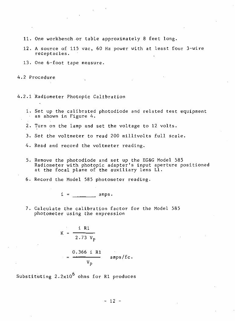
4.2.1 Radiometer Photopic Calibration
1. Set up the calibrated photodiode and related test equipmentas shown in Figure 4.
2. Turn on the lamp and set the voltage to 12 volts.
3. Set the voltmeter to read 200 millivolts full scale.
4. Read and record the voltmeter reading.
5. Remove the photodiode and set up the EG&G Model 585Radiometer with photopic adapter's input aperture positionedat the focal plane of the auxiliary lens Ll.
6. Record the Model 585 photometer reading.
i = amps.
7. Calculate the calibration factor for the Model 585photometer using the expression
i RlK =
2.73 Vp
0.366 i Rl= amps/fc.
VP
Substituting 2.2x10 ohms for Rl produces
- 12 -
LI
250mm F.L.
LAMP
REGULATED
POWER SUPPLY
APERTURE
CALIBRATEDDETECTOR
2.2M
DIGITAL
VOLTMETER
MODEL 585RADIOMETER
PHOTOPICADAPTER
Figure 4. Photopic calibration of radiometer.
- 13 -
8.05xl05 iK = amps/fc.
VP
Illuminance is related to the Model 585 current reading, i.. by
the expression
Ll 2E,. = lumen/ftK
or equivalently
10.76 i.i / 2lumen/m .
K
Express Ey in visual stellar magnitude by using a zero
magnitude star having an illuminance £„„ of 2.65x10²
lumen/m as a reference. (Ref. RCA Electro Optics
Handbook, p66). Illuminance produced by the collimator can be
expressed in terms of visual stellar magnitude using the
expression
17Jvm = -2.5 logEvo
where m is the visual magnitude corresponding to £„.
8. Set up the equipment as shown in Figure 5. Use a diagonalmirror and an 8-inch or larger primary mirror with knownreflectivities.
9. Turn on the Control Unit and radiometer and allow 5 to 10minutes for the equipment to stabilize.
10. Set the Source A ND filter wheel to the OPEN position.
11. Set the Source A electrical control to maximum.
- 14 -
DIAGONAL MIRROR
PHOTOPIC
ADAPTER
585 RADIOMETER
8-INCH
MIRROR
INDICATORUNIT
Figure 5. Collimator output calibration.
- 15 -
12. Record the digital display and Model 585 radiometerreadings.
13. Using the electrical control reduce the display reading to4.50 and record the radiometer and display readings.
14. Continue to reduce the display reading in 0.5 volt stepsuntil the display reads 2.00. Record the display andradiometer readings at each step.
15. Repeat Steps 10 through 14 using Sources B and C.
4.2.2 Neutral Density Filter Calibration
1. Using the equipment setup in Figure 5, set the filterwheel.of Source A to OPEN.
2. Record the radiometer reading, !,->.
3. Set the ND filter wheel of Source A to 1.0 and record theradiometer reading, i.. Q.
4. Calculate the optical transmittance of the ND 1.0 filter byusing the expression
'1.0
5. Set the ND filter wheel to 2.0 and record the radiometerreading, i2 Q- Calculate the optical transmittance ofthe ND 2.0 filter by the same method used in Step 4.
6. Set the ND filter wheel to 3.0 and record the radiometerreading. Calculate the optical transmittance of the ND3.0 filter as in Steps 4 and 5.
7. Set the Source A electrical control for a minimum readingon the display.
8. Repeat Steps 1 through 7 using Sources B and C.
- 16 -
5 CONCLUSIONS AND RECOMMENDATIONS
The Star Field Simulator in its final configuration met all the
design objectives, except for the maximum brightness of -0.8
visual magnitude. When the collimator diameter was increased to
8 inches and the beam divergence reduced from 0.2 milliradian to
4 microradian, the losses associated with transferring light from
the lamp to the collimator were too great to reach the desired
upp'er limit of brightness. By using the most powerful lamps
available, within the current capacity of the power supply, and
adding condenser lenses to the light sources, the goal of -0.8
visual magnitude was still not achieved.
Two approaches are available for a relatively simple solution to
this problem.
1. Replace the present power supply with one that has a higher
current capacity. With more power available the lamps may
be changed to increase light output. This is straight
forward, but the result is more heat dissipated inside the
Control Unit.
2. Replace the lamps with a commercially available point
source assembly supplied buy Oriel Corporation which has
the lamp, condenser optics and a focusing lens included in
- 17 -
a small package. The point source produces a concentrated
spot of light with high brightness that can be .efficiently
coupled to the fiber optics cable. The present power
supply capacity is adequate to operate three point
sources. The present lamp and condenser assembly would
need to be replaced with the point source assembly.
The second approach is preferable because light transfer to the
fiber cables is efficient and the heat dissipated by the power
supply and lamps within the Control Unit is held to present


![divya.gopinath@nasa.gov arXiv:1912.00289v1 [cs.CV] 1 Dec 2019 · Gopinath, Divya SGT Inc, NASA AMES divya.gopinath@nasa.gov Corina Pasareanu NASA AMES, Carnegie Mellon University](https://static.documents.pub/doc/80x56/5fc142313399b519b35b4a72/divyagopinathnasagov-arxiv191200289v1-cscv-1-dec-2019-gopinath-divya-sgt.jpg)
