RAFT RAFT Radar Fence Transponder Radar Fence Transponder Phase 0/1 Safety Review 16 Phase 0/1 Safety Review 16 Dec 04 Dec 04 Bob Bruninga, PE Bob Bruninga, PE MIDN 1/C Eric Kinzbrunner MIDN 1/C Eric Kinzbrunner MIDN 1/C Ben Orloff MIDN 1/C Ben Orloff MIDN 1/C JoEllen Rose MIDN 1/C JoEllen Rose
Phase 0/1 Safety Review 16 Phase 0/1 Safety Review 16 Dec 04Dec 04Bob Bruninga, PEBob Bruninga, PE
MIDN 1/C Eric Kinzbrunner MIDN 1/C Eric Kinzbrunner MIDN 1/C Ben OrloffMIDN 1/C Ben Orloff
MIDN 1/C JoEllen RoseMIDN 1/C JoEllen Rose
RAFT TeamRAFT Team Spacecraft (US Naval Academy)Spacecraft (US Naval Academy)
• Bob Bruninga (PI)Bob Bruninga (PI)• MIDN 1/C Eric Kinzbrunner , MIDN 1/C Ben Orloff, MIDN 1/C JoEllen RoseMIDN 1/C Eric Kinzbrunner , MIDN 1/C Ben Orloff, MIDN 1/C JoEllen Rose
Launch Integration (Space Test Program)Launch Integration (Space Test Program)• Chief Of Integration & Ops: Capt Yvonne Fedee Chief Of Integration & Ops: Capt Yvonne Fedee • Payload Manager: Mr Perry BallardPayload Manager: Mr Perry Ballard• Back Up Payload Manager: Lt Reann CaldwellBack Up Payload Manager: Lt Reann Caldwell• Payload Integration Engineer(PIE): Mr Carson TaylorPayload Integration Engineer(PIE): Mr Carson Taylor• Launcher & Back Up PIE: Mr Scott RitterhouseLauncher & Back Up PIE: Mr Scott Ritterhouse• Safety Engineer (SE): Ms. Theresa ShafferSafety Engineer (SE): Ms. Theresa Shaffer• Launcher & Back up SE: Mr Darren BromwellLauncher & Back up SE: Mr Darren Bromwell
Assumption: Launch NET February 2006Assumption: Launch NET February 2006
RAFT KickoffRAFT Kickoff Apr 04 Apr 04 RAFT USNA SRRRAFT USNA SRR Sep 04 Sep 04 RAFT PDRRAFT PDR 19 Nov 0419 Nov 04 Launcher CDR Launcher CDR Nov 04 Nov 04 RAFT Phase 0/1 SafetyRAFT Phase 0/1 Safety 16 Dec 0416 Dec 04 RAFT CDRRAFT CDR Feb 05 Feb 05 RAFT Phase 2 SafetyRAFT Phase 2 Safety Feb 05 Feb 05 RAFT Flight Unit TestingRAFT Flight Unit Testing May 05 May 05 RAFT Phase 3 SafetyRAFT Phase 3 Safety Aug 05 Aug 05 RAFT Delivery/InstallRAFT Delivery/Install Oct 05 Oct 05 RAFT Flight (STS-116)RAFT Flight (STS-116) 09 Feb 06 09 Feb 06
Key Milestones: ScheduleKey Milestones: Schedule
So Many CUBEsatsSo Many CUBEsats30 to 50 in Construction30 to 50 in Construction
AIAA/USUSmall Sat Conference
30% of papers were for PICO, NANO and CUBEsats
All smaller than 10 cm
How to Track them???
Mission StatementMission StatementThe mission of RAFT is:The mission of RAFT is:
To provide the Navy Space Surveillance (NSSS) radar fence To provide the Navy Space Surveillance (NSSS) radar fence with a with a means to determine the boundsmeans to determine the bounds of a constellation of of a constellation of PicoSats otherwise undetectable by the radar fencePicoSats otherwise undetectable by the radar fence
To enable NSSS to independently To enable NSSS to independently calibrate their transmit and calibrate their transmit and
receive beamsreceive beams using signals from RAFT. using signals from RAFT.
This must be accomplished with This must be accomplished with two PicoSatstwo PicoSats, one that will , one that will actively transmit and receive, and one with a passively actively transmit and receive, and one with a passively augmented radar cross-section.augmented radar cross-section.
Additionally, RAFT will provide experimental Additionally, RAFT will provide experimental communications communications transponderstransponders for the Navy Military Affiliate Radio System, the for the Navy Military Affiliate Radio System, the United States Naval Academy’s Yard Patrol crafts, and the United States Naval Academy’s Yard Patrol crafts, and the Amateur Satellite Service.Amateur Satellite Service.
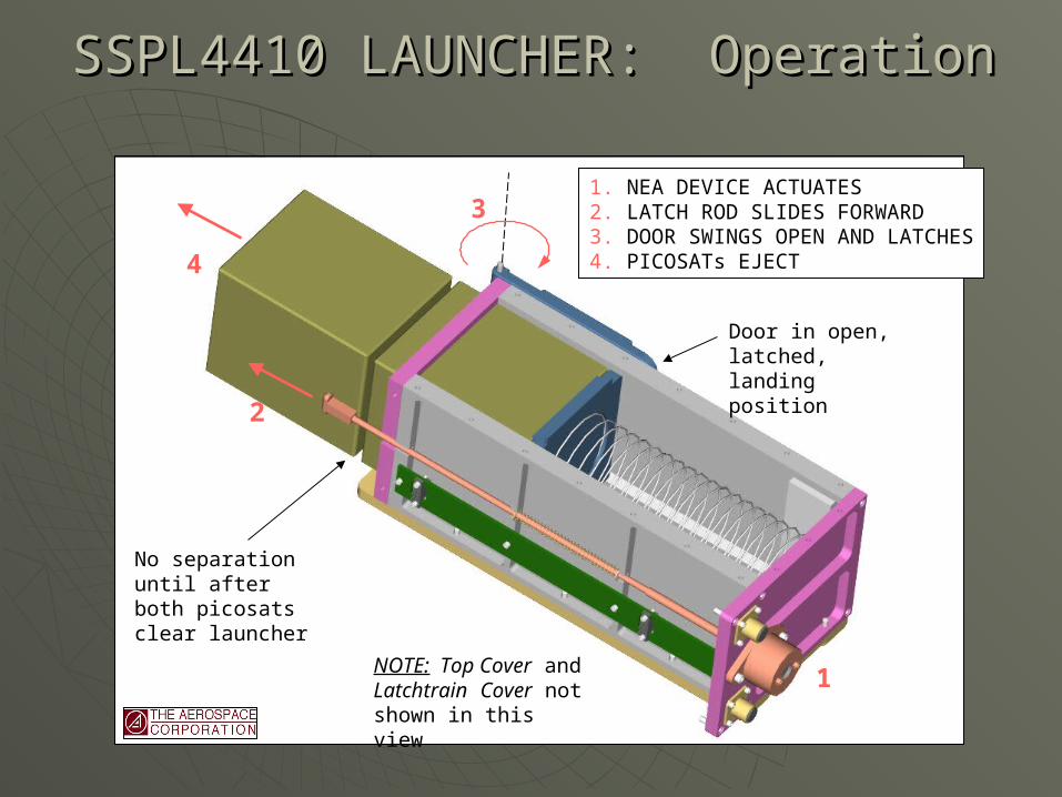
NOTE: Top Cover and Latchtrain Cover not shown in this view
No separation until after both picosats clear launcher
RAFTRAFTDeploymentDeployment
Velocity of CM:
1.00 m/s
Velocity of RAFT:
0.57 m/s
Velocity of MARScom:
1.57 m/s
Air Track Separation TestAir Track Separation Test
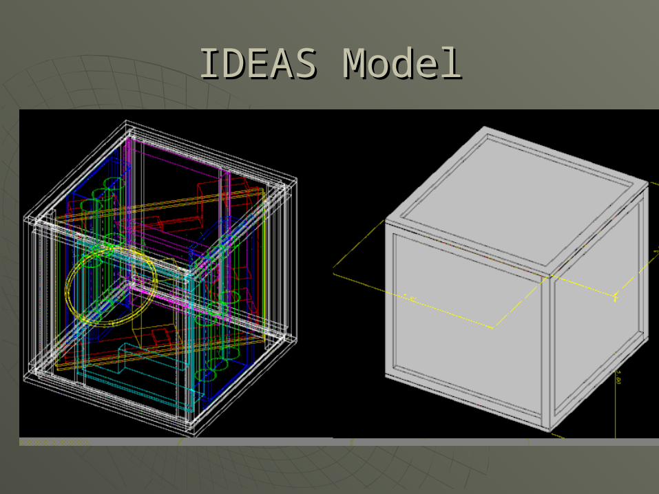
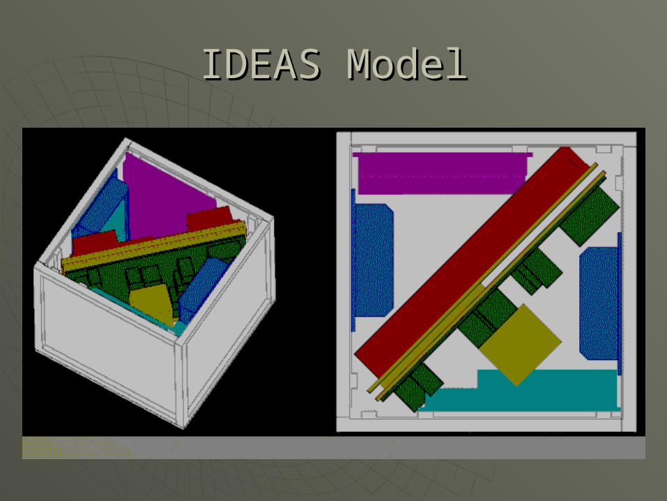
IDEAS ModelIDEAS Model
IDEAS ModelIDEAS Model
AssemblyAssembly
Solar Panel DesignSolar Panel Design
COTS Silicon Cells on PCB panel
Covered with Clear Teflon Coating
1.5 Watt panel
Mechanically rugged for rain/hail/birds
PCsat Flight Heritage
Top PanelTop Panel
VHF Antenna holes
HF whip hole
Antenna pockets for other satellite
RAFT1 RAFT1 Internal Internal DiagramDiagram
TopTopViewView
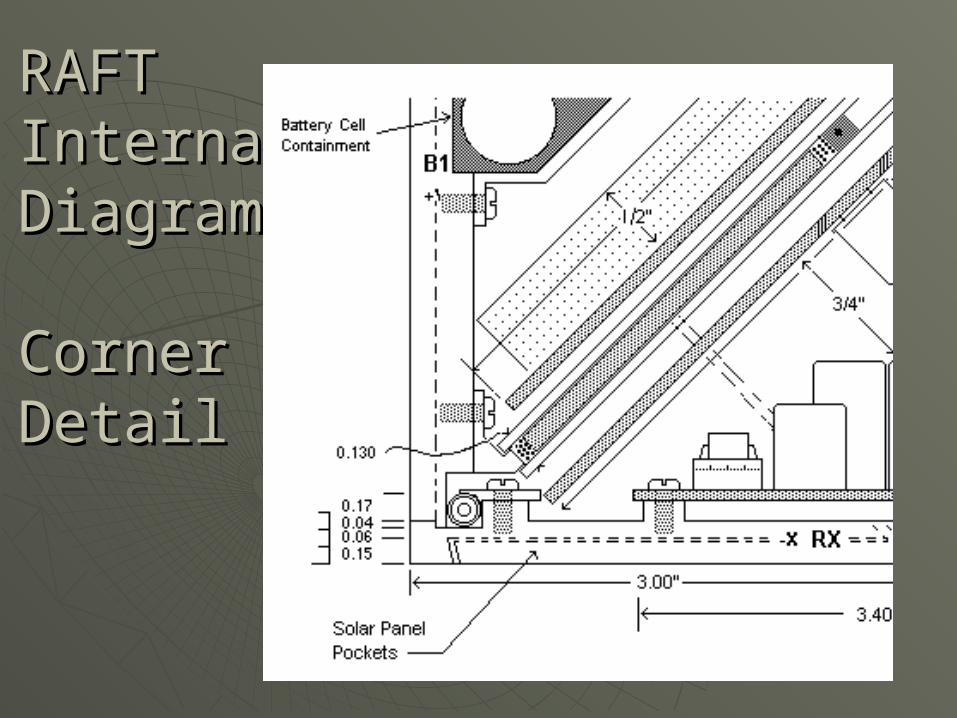
RAFT RAFT Internal Internal DiagramDiagram
CornerCornerDetailDetail
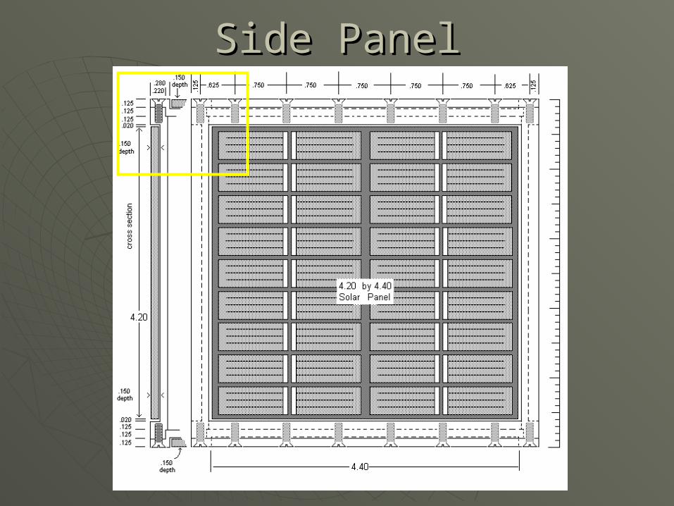
Side PanelSide Panel
Side Panel DetailSide Panel Detail
Loaded Side
.25” thick
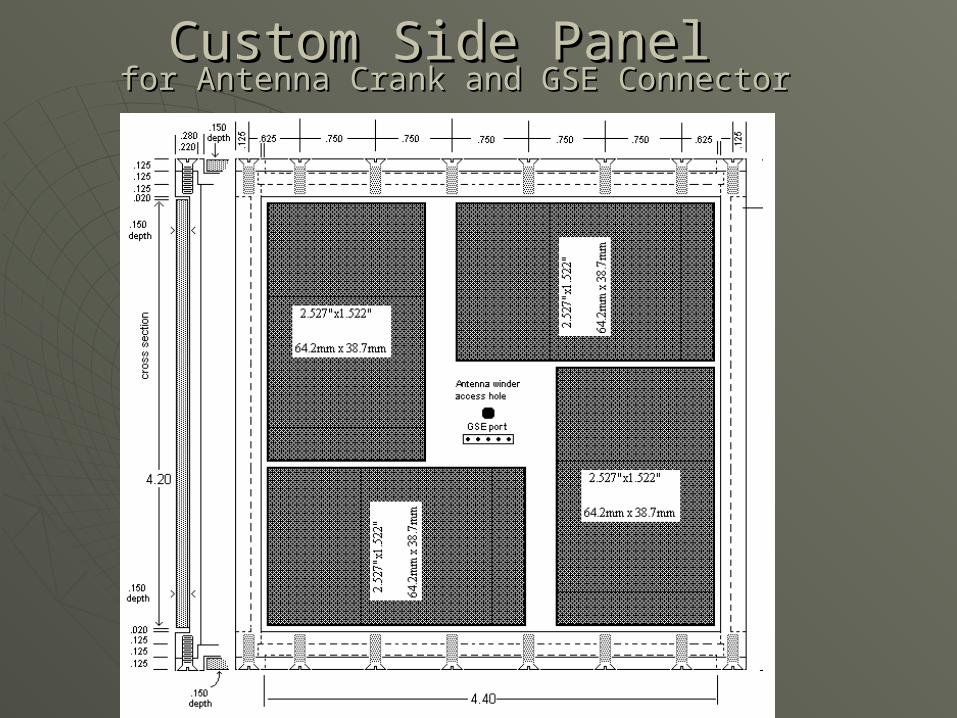
Custom Side Panel Custom Side Panel for Antenna Crank and GSE Connectorfor Antenna Crank and GSE Connector
ITEM QTY DESCRIPTION
5 1 DOOR
PICOSAT
PUSHER
MAINSPRING
PRELOAD BLOCK
24
2 1
13
1 2
PARTS LIST
1
2
45
8
6
9
3
6
8
7
9 NEA DEVICE
BACK COVER
LATCH
LATCHROD
1
1
1
1
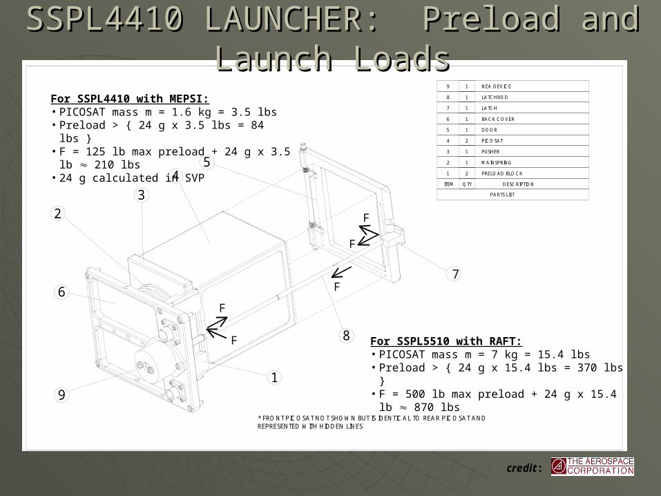
* FRONT PICOSAT NOT SHOWN BUT IS IDENTICAL TO REAR PICOSAT AND REPRESENTED WITH HIDDEN LINES
F
F
F
F
F7
ITEM QTY DESCRIPTION
5 1 DOOR
PICOSAT
PUSHER
MAINSPRING
PRELOAD BLOCK
24
2 1
13
1 2
PARTS LIST
1
2
45
8
6
9
3
6
8
7
9 NEA DEVICE
BACK COVER
LATCH
LATCHROD
1
1
1
1
* FRONT PICOSAT NOT SHOWN BUT IS IDENTICAL TO REAR PICOSAT AND REPRESENTED WITH HIDDEN LINES
F
F
F
F
F7
For SSPL4410 with MEPSI:• PICOSAT mass m = 1.6 kg = 3.5 lbs• Preload > { 24 g x 3.5 lbs = 84 lbs } • F = 125 lb max preload + 24 g x 3.5 lb 210 lbs• 24 g calculated in SVP
For SSPL5510 with RAFT:• PICOSAT mass m = 7 kg = 15.4 lbs• Preload > { 24 g x 15.4 lbs = 370 lbs }• F = 500 lb max preload + 24 g x 15.4 lb 870 lbs
SSPL4410 LAUNCHER: Preload and SSPL4410 LAUNCHER: Preload and Launch LoadsLaunch Loads
EPS and Solar Power EPS and Solar Power BudgetBudget
Computing average solar power for a cube satellite taking weighted average of all 26 possible orientations.
This analysis is for an ISS orbit with a maximum eclipse of 39% with a 25% efficient solar cell.
Raft1 Block DiagramRaft1 Block Diagram
Solar Power BudgetSolar Power Budget
Conclusion: The PCsat panels per side of the satellite and a 39% eclipse time, an average available bus load of 0.96 watts will be available to the spacecraft.
SCef f =Solar Cell Efficiency
Id=Elements of Inherent Degradation
a=Sun Angle
n=number of exposed cells
A=area of one cell
t=exposure multiple
ttotal=total number of exposures
Td=Time in Daylight
Te=Time in EclipseXd=Daylight path efficiency
SCef f (%) 25 25 25
Id 0.77 0.77 0.77
SolarConstant 1367 1367 1367
PBOL (W/m2) 263.15 263.15 263.15
a (deg) 90 45 33
P (W/m2) 263.15 186.07 143.32n 4 8 12
A (m2) 0.0028 0.0028 0.0028
P total (W) 2.95 4.17 4.82
t 6 12 8
ttotal 26 26 26
x 1/4 1/2 1/3Pav g (W) 0.6801 1.9237 1.4817
P totalav g (W) 2.08
Td 0.61
Te 0.39
Xe 0.65
Xd 0.85
L (W) 0.96
Xe=Eclipse path efficiency
L=BusLoad
PBOL=SCef f *Id*SolarConstant
P=PBOL*sin(a)
L=(P totalav g*Xe*Xd*Td)/(Te*Xd+Td*Xe)
P totalav g=Pav g1+Pavg2+Pav g3
P total=P*n*A
x=t/ttotal
Pav g=P total*x
RAFT1 Required Power RAFT1 Required Power BudgetBudget
Current (mA) Normal Avrg (mA) PSK-31 Avrg (mA) STBY Avrg (mA)VHF FM TX 500.00 2% 10.00 10% 50.00 1% 5.00UHF FM RX 30.00 100% 30.00 100% 30.00 100% 30.00
MARScom Required Power MARScom Required Power BudgetBudget
Current (mA) Normal Current (mA) YPSATCOM Current (mA)VHF FM RX 30.00 100% 30.00 100% 30.00UHF AM RX 30.00 0% 0.00 100% 30.00SSB Exciter 50.00 8.34% 4.17 8.34% 4.17
1W Linear PA 100.00 8.34% 8.34 8.34% 8.34Decoder 10.00 100% 10.00 100% 10.00
20% Reserve 8.00 8.00 8.00Avrg (mA) 60.51 90.51
Normal Use YPSATCOM AvalibleAvrg (mA) 60.51 90.51 114.2857143
System (Volts) 8.40 8.40 8.4Avrg (Watts) 0.51 0.76 0.96
Power SystemPower System
Simplified Power SystemSimplified Power System
Charge in Parallel
Transmit in Series
Duty cycle 4%
Operations Safety FeaturesOperations Safety Features
All Transmitter circuits time-out to OFF
Post Cold Test Battery Post Cold Test Battery ConditionCondition
(No Leakage)(No Leakage)
Battery Cold Test Time LineBattery Cold Test Time Line
-60 °C Battery Tests-60 °C Battery Tests
Triple walled chamber
Sealed for condensation
Adding
Dry Ice
30 Hour test @ -60C
-60 °C Battery Test: Thermal -60 °C Battery Test: Thermal ConditionsConditions
Thermal Battery Test
-100
-80
-60
-40
-20
0
20
40
0 5 10 15 20 25 30 35 40 45 50
Time (hrs)
Tem
per
atu
re (
°C)
Batteries
Can
Ice
Post -60 °C Charge Temp in Post -60 °C Charge Temp in VacuumVacuum
0
5
10
15
20
25
30
35
0.00 5.00 10.00 15.00 20.00 25.00
Time (hr)
Te
mp
°C
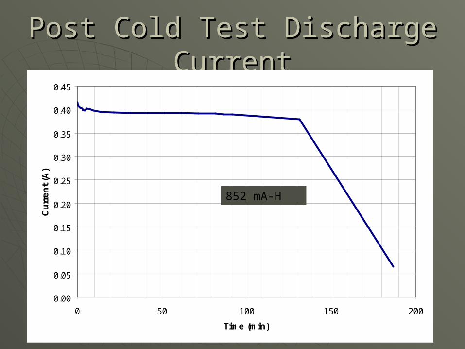
Post Cold Test Discharge Post Cold Test Discharge CurrentCurrent
0.00
0.05
0.10
0.15
0.20
0.25
0.30
0.35
0.40
0.45
0 50 100 150 200
Time (min)
Cu
rre
nt
(A)
852 mA-H
PCsat Solar Panel I-V CurvePCsat Solar Panel I-V CurveVoltage vs. Current
0
0.01
0.02
0.03
0.04
0.05
0.06
0.07
0.08
0 1 2 3 4 5 6 7 8 9 10 11
Volts
Am
ps
Amps @ 0
Amps @ 20
Amps @ 30
Amps @ 40
Amps @ 50
Amps @ 60
discharged
Full charge
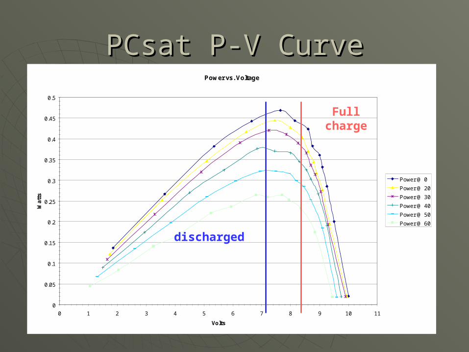
PCsat P-V CurvePCsat P-V CurvePower vs. Voltage
0
0.05
0.1
0.15
0.2
0.25
0.3
0.35
0.4
0.45
0.5
0 1 2 3 4 5 6 7 8 9 10 11
Volts
Wa
tts
Power @ 0
Power @ 20
Power @ 30
Power @ 40
Power @ 50
Power @ 60
discharged
Full charge
Dead Battery Charge Dead Battery Charge EfficiencyEfficiency
Dead Battery Recovery TestDead Battery Recovery Test
CommunicationCommunication RAFT1 ITU Request Form submitted.RAFT1 ITU Request Form submitted.
Fracture Control Plan Fracture Control Plan Captive & RedundantCaptive & Redundant Fastener integrity Fastener integrity Captive & RedundantCaptive & Redundant Structural model of RAFTStructural model of RAFT Ideas model, Ideas model,
BucklingBuckling Venting analysisVenting analysis Done. 0.04 “Done. 0.04 “ Simple mechanismsSimple mechanisms AntennasAntennas Materials / OutgassingMaterials / Outgassing COTS, ReplaceCOTS, Replace Conformal coat PC boardsConformal coat PC boards YesYes Wire sizing and fusingWire sizing and fusing #24, fuse 1 amp#24, fuse 1 amp Radiation hazardRadiation hazard Below 0.1v/mBelow 0.1v/m Battery safetyBattery safety YesYes Shock and vibrationShock and vibration YesYes
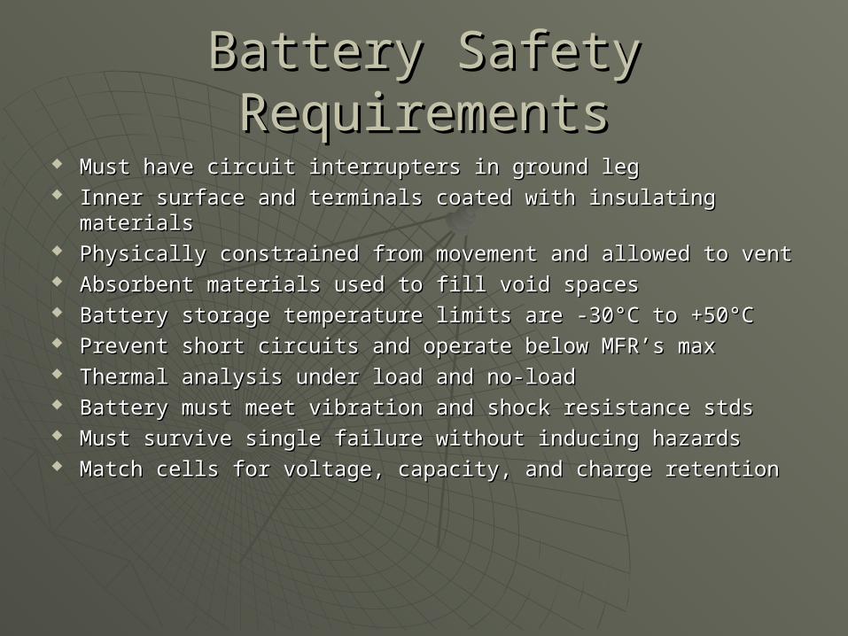
Must have circuit interrupters in ground legMust have circuit interrupters in ground leg Inner surface and terminals coated with insulating materialsInner surface and terminals coated with insulating materials Physically constrained from movement and allowed to ventPhysically constrained from movement and allowed to vent Absorbent materials used to fill void spacesAbsorbent materials used to fill void spaces Battery storage temperature limits are -30°C to +50°CBattery storage temperature limits are -30°C to +50°C Prevent short circuits and operate below MFR’s maxPrevent short circuits and operate below MFR’s max Thermal analysis under load and no-loadThermal analysis under load and no-load Battery must meet vibration and shock resistance stdsBattery must meet vibration and shock resistance stds Must survive single failure without inducing hazardsMust survive single failure without inducing hazards Match cells for voltage, capacity, and charge retentionMatch cells for voltage, capacity, and charge retention
Assumption: Launch NET February 2006Assumption: Launch NET February 2006
RAFT KickoffRAFT Kickoff Apr 04 Apr 04 RAFT USNA SRRRAFT USNA SRR Sep 04 Sep 04 RAFT PDRRAFT PDR 19 Nov 0419 Nov 04 Launcher CDR Launcher CDR Nov 04 Nov 04 RAFT Phase 0/1 SafetyRAFT Phase 0/1 Safety 16 Dec 0416 Dec 04 RAFT CDRRAFT CDR Feb 05 Feb 05 RAFT Phase 2 SafetyRAFT Phase 2 Safety Feb 05 Feb 05 RAFT Flight Unit TestingRAFT Flight Unit Testing May 05 May 05 RAFT Phase 3 SafetyRAFT Phase 3 Safety Aug 05 Aug 05 RAFT Delivery/InstallRAFT Delivery/Install Oct 05 Oct 05 RAFT Flight (STS-116)RAFT Flight (STS-116) 09 Feb 06 09 Feb 06