88
RAILROAD COMMISSION OF TEXAS Directional Surveys and Associated Issues Keith May Technical Permitting Engineering Unit

RAILROAD COMMISSION OF TEXAS
Directional Surveys and Associated Issues
Keith May Technical Permitting
Engineering Unit
Presentation Overview
Introduction Survey Requirements
Submission Procedures Engineering Review

Presentation Overview
Introduction Survey Requirements
Submission Procedures Engineering Review

Directional Drilling
Thanks to advancements in drilling technology, drillers have incredible control and precision over
their drilling operations.
http://tntenergy.ca/directional-drilling

Directional Drilling
Measurement while drilling or MWD tools allow the driller to “steer” the drill bit. After each joint of pipe is added positional data is transmitted up the wellbore. What we end up with is X, Y and Z coordinates of the wellbore.

Vertical Well
6
10’
10’
70’
90’
Even vertical wells can have substantial drifts from their intended direction.

An Example Drilling a 5280’ horizontal with 3 degree error in a particular direction would result in offset of 276’ in that direction!
Permitted Location
Lease Line
276’
Only 3°!

An Example Drilling a 5280’ horizontal with 3 degree error in a particular direction would result in offset of 276’ in that direction!
• Typical horizontals in Eagle Ford are thousands of feet in length.
• Typical lease line spacing is 330’.
• Must be in compliance with spacing rules.

The RRC has a job to do Why must surveys and inclination reports be submitted? • To insure lease line and wellbore spacing
rules are being followed. • Protection of oil and gas reservoirs

10
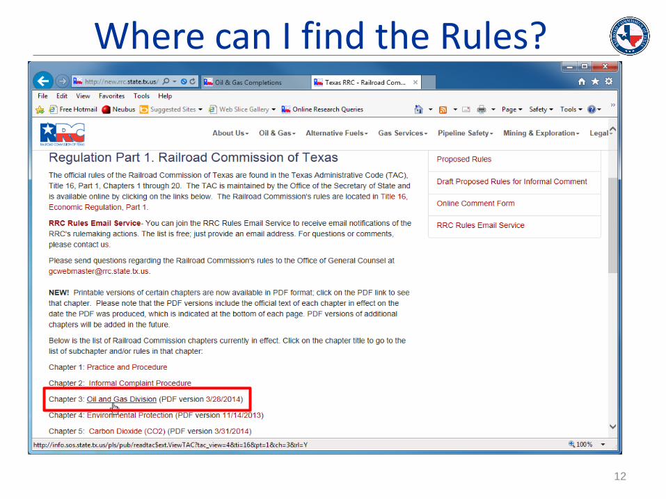
Where can I find the Rules?

11
Where can I find the Rules?
12
Where can I find the Rules?

13
Where can I find the Rules?

Presentation Overview
Introduction Survey Requirements
Submission Procedures Engineering Review

Presentation Overview
Introduction Survey Requirements
Submission Procedures Engineering Review

Statewide Rule 3.11 (SWR 11)
SWR11 outlines the requirements for inclination and directional surveys
Purpose: to accurately confine well location in 3-
D space (X, Y, Z)
*Different survey combinations required depending on wellbore profile*

Survey Types Inclination surveys
Inclination and offset data only (Form W-12) No coordinates or directional data
Directional surveys
Gyroscopic borehole survey (GYRO) Measurement while drilling (MWD) Provide coordinate data (X, Y, and Z)
Each survey type has different data and certification requirements. It pays to get it right the first time.

Statewide Rule 3.11 (SWR 11)
INCLINATION SURVEYS
Required of any well drilled/deepened with
rotary tools
First data point shall not exceed 500’ deep
Data points not to exceed 1000’ apart
Outlines several exceptions to the rule based
on depth and spacing to lease lines

Statewide Rule 3.11 (SWR 11)
INCLINATION SURVEYS
Submitted on form W-12 by operator
Performed by drilling company
Certified by drilling company and operator
Report horizontal offset without direction, so
offset direction assumed to be toward nearest
lease line

20
Form W-12

21
Shot points must begin within 500’ of the surface
shall not exceed 1000’ apart.
Shows cumulative displacement from vertical.
Must not exceed distance to nearest lease line
Form W-12

Accumulative displacement is given without a
compass direction, must not exceed distance to
nearest lease line.
Drilling company representative certifies accuracy
of the data
Operator certifies that the well was not intentionally
deviated from vertical.
22
Form W-12
23
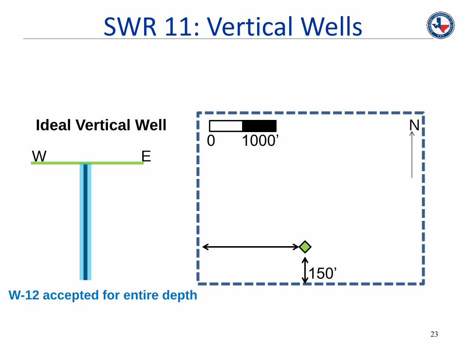
N 0 1000’
150’
W E
Ideal Vertical Well
W-12 accepted for entire depth
SWR 11: Vertical Wells

24
N
150’
Actual Well
SWR 11: Vertical Wells
W E 0 1000’
155’
75’
65’
10’
Cumulative total displacement: 75’+65’+10’=155’
Actual displacement: 10’

25
DIRECTIONAL SURVEYS
Required for any intentionally-deviated well
Data points no more than 200’ apart, *beginning within 200’ of the surface
May begin immediately below surface casing depth (W-12 required in this case)
SWR 11: Directional Surveys
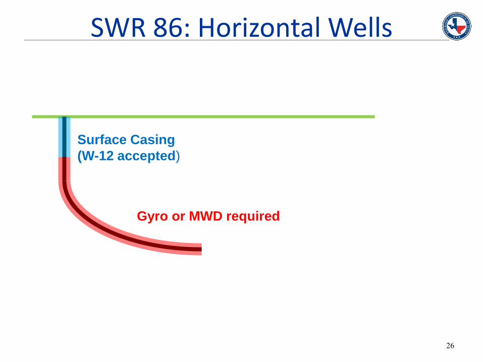
26
Surface Casing
(W-12 accepted)
Gyro or MWD required
SWR 86: Horizontal Wells
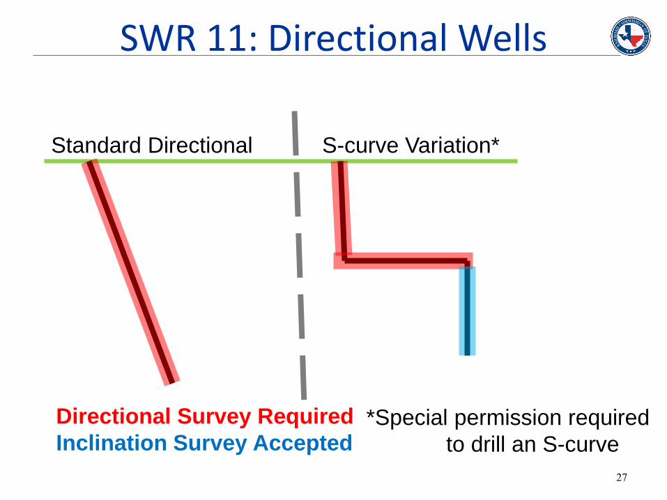
27
Standard Directional S-curve Variation*
Directional Survey Required
Inclination Survey Accepted *Special permission required
to drill an S-curve
SWR 11: Directional Wells
Statewide Rule 3.86 (SWR 86)
SWR 86 outlines requirements for Horizontal Drainhole Wells
Purpose: to establish standard requirements for
horizontal wells
*Directional surveys required*

29
SWRs 11 & 86: Surveys • Common mistakes:
— WRONG SURVEYS for wellbore profile — Surveys missing completely — Surveys lacking certification — Surveys don’t tie-in — Surveys attached for wrong well
• Solution: ― Survey company must correct and resubmit

30
Outlines requirements for Submission and Certification of Directional Surveys:
• Survey Company Name
• Name and title of individual performing survey
• Date survey was performed
• Type of survey conducted
• Complete well identification
• Depths surveyed
• Drilling permit plat with bottom hole location.
Statewide Rule 3.12 (SWR 12)

31
I, name, an authorized employee of THE SURVEY
COMPANY, have verified the GYRO/MWD survey
performed on 04/01/2013 to 04/02/2013, from 200’ to
15000’. The data are true, correct, complete and within
the limitations of the tool. This survey was conducted at
the request of OPERATOR for LEASE WELL# (API#)
drilled in TRAVIS COUNTY, Texas.
SWR 12: Proper Certification

32
Directional Surveys must be submitted and certified by the company that performed the
survey.
They cannot be accepted directly from the operator.
SWR 12: Directional Surveys

33
• Common mistakes:
– Uploading cover letter instead
– Double-certifying another company’s interval
– Certification completely missing
• Solution:
– Survey company must correct and resubmit
SWR 12: Proper Certification

Presentation Overview
Introduction Survey Requirements
Submission Procedures Engineering Review

Presentation Overview
Introduction Survey Requirements
Submission Procedures Engineering Review

36
Submission of Directional surveys is the responsibility of the survey company.
Survey companies:
• Must appear on list of approved survey companies*
• Must have active P-5 (Organization Report)
• Must upload certification letter as a separate file
Submission Procedures

37
Surveys can be submitted hardcopy through the mail or through the RRC online system.
• Submitted hard copy takes at least two (2) weeks.
• Surveys submitted online are immediately available for review.
Submission Procedures
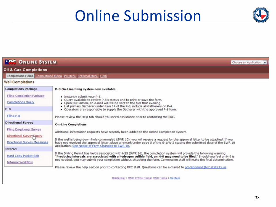
38
Online Submission

39
Online Submission

40
Online Query

41
Search online by API number to verify submission
Online Query

Presentation Overview
Introduction Survey Requirements
Submission Procedures Engineering Review

Presentation Overview
Introduction Survey Requirements
Submission Procedures Engineering Review

44
• Survey completeness
• Tie-ins
• Certification
• Well construction
• Wellbore profile
• Abandoned wellbore
• Required plugs and cementing
• Spacing
• Lease line spacing
• Between-well spacing
• Permitted location
• NPZs
Engineering Review

45
• RRC will accept specific combinations of surveys that represent a complete picture of the entire wellbore.
• All surveys must tie in at given depths with identical X,Y, and Z coordinates.
Survey Completeness: Tie ins

46
Depth Incl. Azimuth +N/-S +E/-W Tool
600’ 2.3 270° 5 20 GYRO
800’ 3.3 268° 9 -80 GYRO
Depth Incl. Azimuth N-S E-W Tool
800’ 3.3 268° 9 N 80 W GYRO
1000 10 272° 15 N 120 W MWD
Survey A (GYRO)
Survey B (MWD)
We will contact you if the tie-in data are missing.
Tie-in point
Eng Review: Tie-Ins

47
Attachments page of the G-1 or W-2
Eng Review: Certification

48
Wellbore Construction:
• Compiled from inclination and directional surveys
– SWR 11 requires ALL directional surveys
• Well location projected onto Permit Plat
• Permit and As-drilled plat requirements follow
Engineering Review

49
Plat Requirements
(SL)
(PP)
(FTP)
(LTP)
(BHL)
N 0 1000’
Lease boundary
Scale bar
North Arrow
Surface Location (SL)
Penetration Point (PP)
First Take Point (FTP)
Last Take Point (LTP)
Terminus/Bottom Hole
Location (BHL)
Distance to Lease Lines
Eng Review: Construction

50
Permit Location
N 0 1000’
Permit Location As-drilled Location
Eng Review: Construction

51
Wellbore construction
(SL)
(PP)
(FTP) (LTP) (BHL)
Eng Review: Construction

District Offices don’t necessarily review directional surveys, so it is crucial to communicate any intentions to abandon portions of the wellbore with the District Offices directly and in advance.
Sometimes directional surveys indicate abandoned sections of wellbore (pilot holes or sidetracks) that must be plugged.
Eng Review: Construction

53
Wellbore construction
Penetration Point (PP)
Eng Review: Construction

54
Wellbore construction
Penetration Point (PP) Kick-off Point (KOP)
Eng Review: Construction
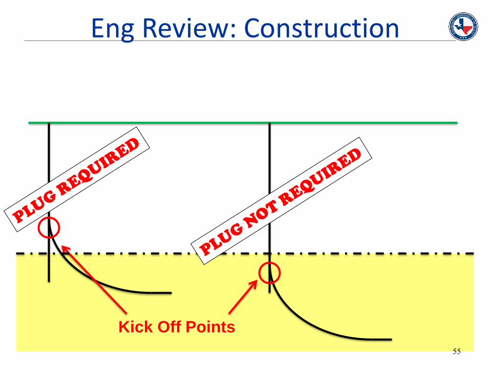
Kick Off Points
55
Eng Review: Construction

Outlines Cementing and Plugging Requirements
Purpose: To isolate and protect usable water and productive formations from migration and
contamination
*Minimum plug dimensions*:
•100’ thick, centered on penetration point
•Additional 10’ required for each 1000’ TVD.
56
Statewide Rule 3.14 (SWR 14)

Form: W-15
• Plugging record on page 2
• Used to calculate plug thickness
57
Eng Review: Construction
The MWD directional survey from _____ indicates an abandoned section of sidetrack 0 below the KOP of
sidetrack 1. The section of abandoned wellbore must comply with section (d)(7) and section (k) of SWR 14.
The operator must provide documentation that it complied with the district office's instructions
concerning plugging the abandoned wellbore prior to sidetracking, as per section (d)(7) of SWR 14.
58
Eng Review: Abandoned Sections

SWR 14
(j) “The district director or the director's delegate shall review and approve the notification of intention to plug in a manner so as to accomplish the purposes of this section.”
• Exceptions may be granted by district offices, not Austin
• Note Job# of communication/notification with District in the remarks section of W-2/G-1
59
Eng Review: Construction

1. Contact District Office:
Acknowledge/advise of SWR 14 violation
Explain circumstances of violation
Make a case for adequate isolation
Formally request an exception to the rule
2. Forward District Office response to Engineering
! Letter from operator to District may not resolve issue
Repeat violations may result in recommendation for administrative penalty action
60
SWR 14 Exceptions

Oil and Gas Division
District Offices:
Abilene
Corpus Christi
Houston
Kilgore
Midland
Pampa
San Angelo
San Antonio
Wichita Falls
10
8A
8
9
7B
7C
5 6
3
2
1
4
61
SWR 14 Exceptions

62
District Office Contact Info

63
District Office Contact Info

64
District Office Contact Info

65
Spacing concerns
N 0 1000’
Lease Line Spacing
Between-well
spacing (horizontal
wells)
Between-well
spacing (vertical
wells)
Eng Review: Spacing
66
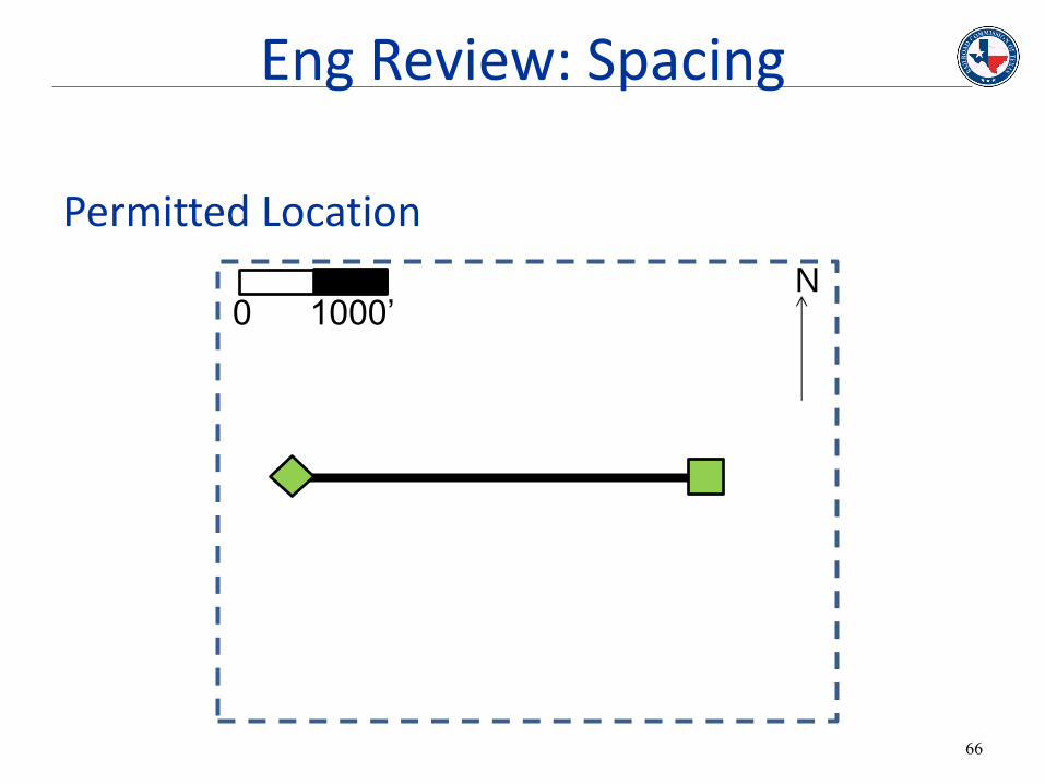
Permitted Location
N 0 1000’
Eng Review: Spacing

67
Permitted As-Drilled Location
N 0 1000’
If the as-drilled location does not match the permit location, the permit may need to be revised.
Eng Review: Spacing

68
Permitted As-Drilled Location
0 1000’
If the as-drilled location does not match the permit location, the permit may need to be revised. However, this may be the result of an inaccurate North arrow.
Eng Review: Spacing

69
Permitted As-Drilled Location
0 1000’
Eng Review: Spacing

70
Permitted Location
N 0 1000’
Eng Review: Spacing

71
Permitted Location
N 0 500’
If the scale bar is inaccurate, lease line spacing will be unreliable.
Eng Review: Spacing

72
Online messages • Attached if an issue arises
• Dispatched at the end of the day
• No notification is sent when an operator responds, email to notify us directly for rapid response
• Otherwise, we go through all old messages periodically, takes a few days depending on reviewer.
Engineering Review

73
Special Field rules are tailor made rules approved by the Commission for various fields.
There are a couple common rules that are seen in various fields. Here are a few:
• Lease Line spacing
• Well Spacing
• Off lease penetration points
• Box rule
• Heel & Toe Provisions
Special Field Rules

74
Special Field Rules

75
Special Field Rules

76
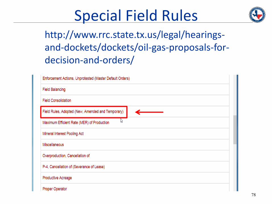
Special Field Rules
This search function shows the key information about the field rules as well as a link to the docket

77
http://www.rrc.texas.gov/legal/hearings-and-dockets/dockets/oil-gas-proposals-for-decision-and-orders/
Special Field Rules
78
http://www.rrc.state.tx.us/legal/hearings-and-dockets/dockets/oil-gas-proposals-for-decision-and-orders/
Special Field Rules
79
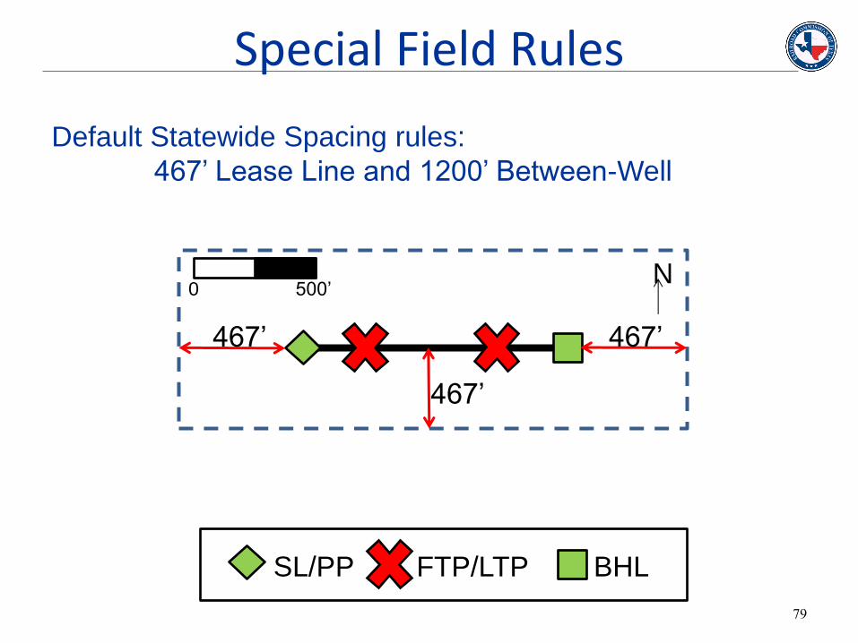
N 0 500’
Default Statewide Spacing rules:
467’ Lease Line and 1200’ Between-Well
467’
467’
467’
SL/PP FTP/LTP BHL
Special Field Rules

80
Take-Point Provisions allow longer drainhole length. Spacing is measured to the take points instead of the SHL and terminus
N 0 500’
467’ 467’ 467’
Take-Point Provisions
SL/PP FTP/LTP BHL

81
N 0 500’
Off-lease penetration points enable operator to have
surface-hole and penetration points outside of lease
467’ 467’ 467’
Off-lease Penetration Points
SL/PP FTP/LTP BHL

82
N 0 500’
Heel and Toe Provisions reduce spacing requirements
measured from take points, parallel to the drainhole
200’ 467’
200’
Heel and Toe Provisions
SL/PP FTP/LTP BHL

83
N 0 500’
Gives operators extra leeway in drilling wellbores. A box is created
around the proposed FTP and LTP, widths depend on the specific
field rules.
As long as the wellbore stays in the box, it is compliant.
467’ 467’
Box/Rectangle Rule
SL/PP FTP/LTP BHL

Plat Incomplete
Directional survey(s) lacking
Directional survey(s) missing
Wrong Directional Survey
Invalid tie-in points
Certification lacking
Double-certification
SWR 14 violation
Off-lease Terminus
Lease-Line Violation
Between-well Spacing violation
Well location doesn’t match Plat
84
Common Online Messages Problem Solution
Check scale bar and North arrow (on plat), amend permit if necessary
Contact District Office
Have surveyor correct cert. letter
Search online query, contact
surveyor
Correct and resubmit

85
Know your required surveys.
Certify and Submit accordingly.
Remarks are helpful.
Special Field Rules are your friend.
Take-Point Provisions
Off-Lease Penetration
Heel/Toe Provisions
Rectangle Rules
As-Drilled Plat requirements
For best results: contact your Engineering Specialist directly in addition to responding to Online Messages.
In Summation
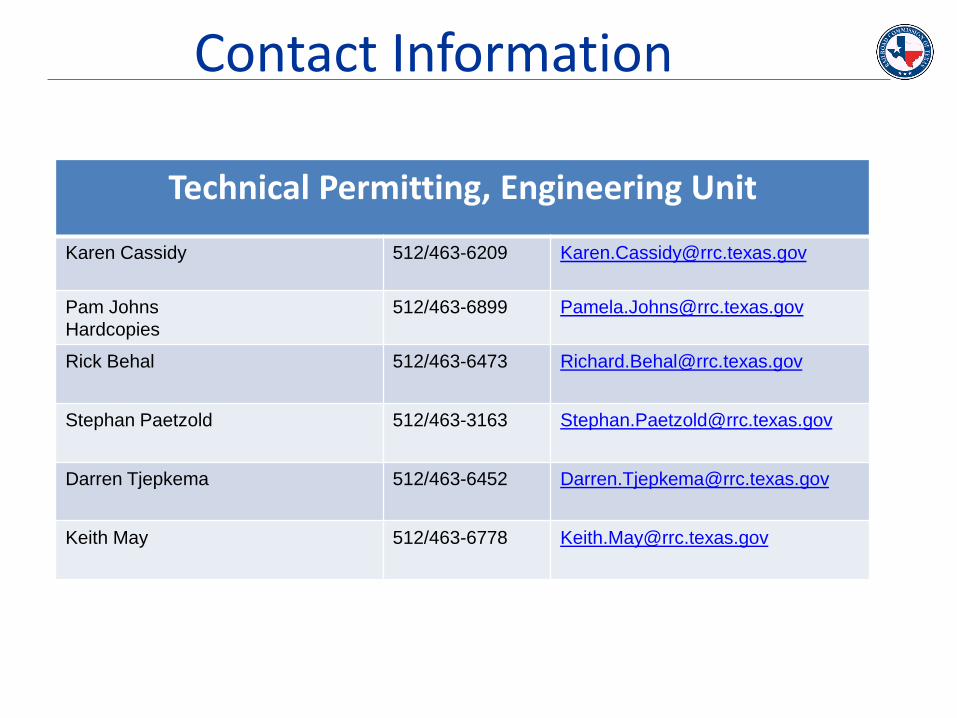
Contact Information
Technical Permitting, Engineering Unit
Karen Cassidy 512/463-6209 [email protected]
Pam Johns
Hardcopies
512/463-6899 [email protected]
Rick Behal
512/463-6473 [email protected]
Stephan Paetzold 512/463-3163 [email protected]
Darren Tjepkema 512/463-6452 [email protected]
Keith May 512/463-6778 [email protected]

Questions?

88
Q: In the vertical section of a horizontal well, what is the directional survey shot point spacing?
A: The shot point spacing is always 200 feet or less for all directional survey in all cases.
Q: If the “correlative interval” is penetrated off-lease but the well is only perfed at a legal location, what does the operator need to do?
A: By statewide default rules, the well is not allowed to penetrate the correlative interval off-lease. However, in some fields special field rules do allow for off-lease POP. Operator is required to serve 21-day notice to the offset mineral owner. (check special field rules)
Q: If special field rules authorize an off-lease penetration point, can the terminus be drilled off-lease?
A: This provision does not allow the terminus to be off-lease.
FAQs


![Welcome [] · 2019. 2. 16. · Speaker Bio Introduction –Noralis, Inc. –12 Years of Experience in Measurement While Drilling (MWD) • 3-years MWD Field Engineer (domestic + international)](https://static.documents.pub/doc/80x56/60f124f872b5ea2768418a17/welcome-2019-2-16-speaker-bio-introduction-anoralis-inc-a12-years.jpg)


