Railway Arch Bridge over the Tajo River in the Alcántara Reservoir Javier MANTEROLA Pr. Dr. Civil Engineer Carlos Fernández Casado,S.L. Madrid, SPAIN [email protected]Antonio MARTÍNEZ Dr. Civil Engineer Carlos Fernández Casado,S.L. Madrid, SPAIN [email protected]Borja MARTÍN Civil Engineer Carlos Fernández Casado,S.L. Madrid, SPAIN [email protected]Miguel Ángel GIL Civil Engineer Carlos Fernández Casado,S.L. Madrid, SPAIN [email protected]Silvia FUENTE Civil Engineer Carlos Fernández Casado,S.L. Madrid, SPAIN [email protected]Lucía BLANCO Civil Engineer Carlos Fernández Casado,S.L. Madrid, SPAIN [email protected]Summary Placed in the High-Speed Railway Line Madrid-Extremadura, the bridge has a total length of 1488m. The span distribution is influenced by the crossing of the Tajo River, which takes place with an arch, 324m long, and dividing the deck over it in six spans of 54m each one. The approach spans are 60m long, inserting two transition spans of 57m. The emblematic element of the bridge is aforementioned arch. With curve directrix, it is formed by a hollow variable section between (4.00m – 3.50m wide; 12.00m – 6.00m high). With its man span length of 324m, it will surpass the bridge over the Contreras Reservoir, currently the largest railway arch bridge executed in Spain. Keywords: Arch bridge, concrete, high-speed railway, cable-stayed, cantilever launching, 1. General description The bridge is placed in the P.K. 4+061.00, and has a total length of 1488m, with a span distribution of 45 + 9x60 + 57 + 324 + 57 + 7x60 + 45m. 1.1. Deck The deck consists on a hollow prestressed concrete section with a height of 4.00m. This slenderness allows the structure to save appropriately the 60m approach spans, and so the 54m spans over the arch which, due to its flexibility, causes complementary bendings. The lower slab is 5.00m wide, and 6.50m the upper one, completed with cantilevers to reach a total width of 14.00m. The web thickness is 0.50m. Concrete HP-50 is used in the approach spans. Concrete HP-70 is necessary in the track over the arch. Fig 1. General definition
Transcript
Railway Arch Bridge over the Tajo River in the Alcántara Reservoir
Javier MANTEROLA Pr. Dr. Civil Engineer Carlos Fernández Casado,S.L. Madrid, SPAIN [email protected]
Javier Manterola, born 1936, received his civil engineering degree from the Technical Univ. of Madrid
Antonio MARTÍNEZ Dr. Civil Engineer Carlos Fernández Casado,S.L. Madrid, SPAIN [email protected]
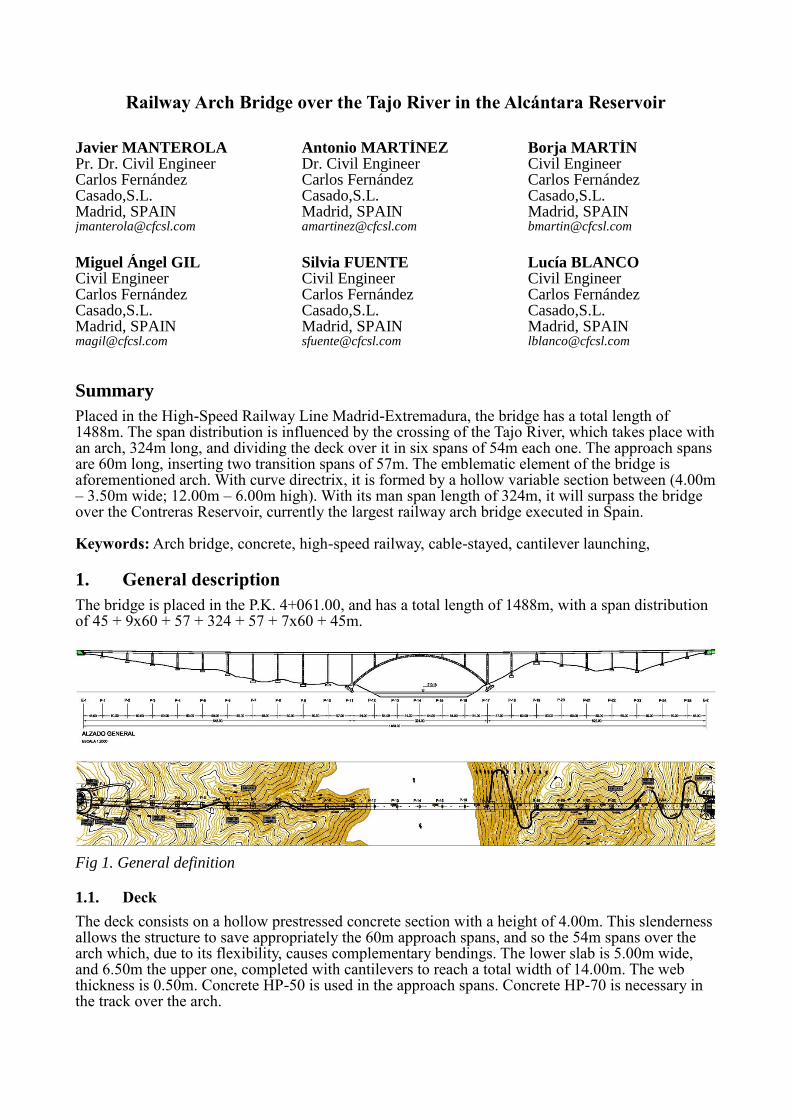
Placed in the High-Speed Railway Line Madrid-Extremadura, the bridge has a total length of 1488m. The span distribution is influenced by the crossing of the Tajo River, which takes place with an arch, 324m long, and dividing the deck over it in six spans of 54m each one. The approach spans are 60m long, inserting two transition spans of 57m. The emblematic element of the bridge is aforementioned arch. With curve directrix, it is formed by a hollow variable section between (4.00m – 3.50m wide; 12.00m – 6.00m high). With its man span length of 324m, it will surpass the bridge over the Contreras Reservoir, currently the largest railway arch bridge executed in Spain.
The bridge is placed in the P.K. 4+061.00, and has a total length of 1488m, with a span distribution of 45 + 9x60 + 57 + 324 + 57 + 7x60 + 45m.
1.1. Deck
The deck consists on a hollow prestressed concrete section with a height of 4.00m. This slenderness allows the structure to save appropriately the 60m approach spans, and so the 54m spans over the arch which, due to its flexibility, causes complementary bendings. The lower slab is 5.00m wide, and 6.50m the upper one, completed with cantilevers to reach a total width of 14.00m. The web thickness is 0.50m. Concrete HP-50 is used in the approach spans. Concrete HP-70 is necessary in the track over the arch.
Fig 1. General definition
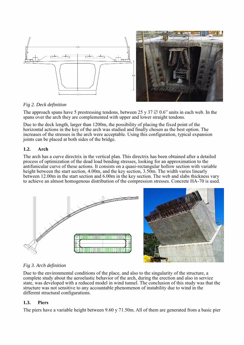
The approach spans have 5 prestressing tendons, between 25 y 37 0.6” units in each web. In the spans over the arch they are complemented with upper and lower straight tendons.
Due to the deck length, larger than 1200m, the possibility of placing the fixed point of the horizontal actions in the key of the arch was studied and finally chosen as the best option. The increases of the stresses in the arch were acceptable. Using this configuration, typical expansion joints can be placed at both sides of the bridge.
1.2. Arch
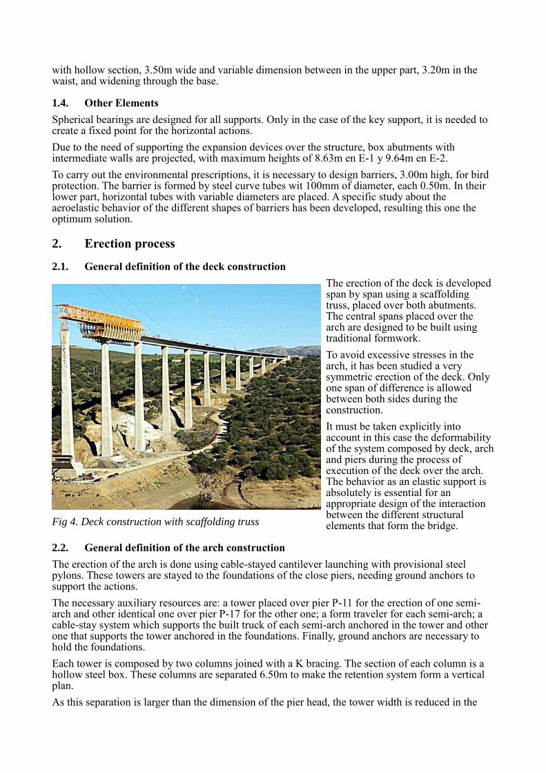
The arch has a curve directrix in the vertical plan. This directrix has been obtained after a detailed process of optimization of the dead load bending stresses, looking for an approximation to the antifunicular curve of these actions. It consists on a quasi-rectangular hollow section with variable height between the start section, 4.00m, and the key section, 3.50m. The width varies linearly between 12.00m in the start section and 6.00m in the key section. The web and slabs thickness vary to achieve an almost homogenous distribution of the compression stresses. Concrete HA-70 is used.
Due to the environmental conditions of the place, and also to the singularity of the structure, a complete study about the aeroelastic behavior of the arch, during the erection and also in service state, was developed with a reduced model in wind tunnel. The conclusion of this study was that the structure was not sensitive to any accountable phenomenon of instability due to wind in the different structural configurations.
1.3. Piers
The piers have a variable height between 9.60 y 71.50m. All of them are generated from a basic pier
Fig 2. Deck definition
Fig 3. Arch definition
with hollow section, 3.50m wide and variable dimension between in the upper part, 3.20m in the waist, and widening through the base.
1.4. Other Elements
Spherical bearings are designed for all supports. Only in the case of the key support, it is needed to create a fixed point for the horizontal actions.
Due to the need of supporting the expansion devices over the structure, box abutments with intermediate walls are projected, with maximum heights of 8.63m en E-1 y 9.64m en E-2.
To carry out the environmental prescriptions, it is necessary to design barriers, 3.00m high, for bird protection. The barrier is formed by steel curve tubes wit 100mm of diameter, each 0.50m. In their lower part, horizontal tubes with variable diameters are placed. A specific study about the aeroelastic behavior of the different shapes of barriers has been developed, resulting this one the optimum solution.
2. Erection process
2.1. General definition of the deck construction
The erection of the deck is developed span by span using a scaffolding truss, placed over both abutments. The central spans placed over the arch are designed to be built using traditional formwork.
To avoid excessive stresses in the arch, it has been studied a very symmetric erection of the deck. Only one span of difference is allowed between both sides during the construction.
It must be taken explicitly into account in this case the deformability of the system composed by deck, arch and piers during the process of execution of the deck over the arch. The behavior as an elastic support is absolutely is essential for an appropriate design of the interaction between the different structural elements that form the bridge.
2.2. General definition of the arch construction
The erection of the arch is done using cable-stayed cantilever launching with provisional steel pylons. These towers are stayed to the foundations of the close piers, needing ground anchors to support the actions.
The necessary auxiliary resources are: a tower placed over pier P-11 for the erection of one semi-arch and other identical one over pier P-17 for the other one; a form traveler for each semi-arch; a cable-stay system which supports the built truck of each semi-arch anchored in the tower and other one that supports the tower anchored in the foundations. Finally, ground anchors are necessary to hold the foundations.
Each tower is composed by two columns joined with a K bracing. The section of each column is a hollow steel box. These columns are separated 6.50m to make the retention system form a vertical plan.
As this separation is larger than the dimension of the pier head, the tower width is reduced in the
Fig 4. Deck construction with scaffolding truss
joint between both elements. The K bracing is composed of horizontal beams placed each 4.00m and diagonal elements. Both of them are steel double T rolled profiles.
The form traveler is a steel auxiliary structure designed to support the formwork of each arch segment and allowing the cast in situ of that segment. The form traveler is supported in the area of the arch that has been recently erected, to prepare the casting of the next segment. These segments are about 3.80m long, taking into account a form traveler with a total weight of 95Tons.
The process has been conceived using 15 couples of stays supporting each semi-arch, and another 15 couples that hold each tower. There is a couple of stays anchored in the arch each three segments. The typical separation of the cables in the tower is 2.00m. Only the first couple needs more separation, because they are almost vertical
2.3. Optimization of the construction process of the arch
Due to the technical constraints of this structure, and looking for the optimization of the use of the auxiliary resources and the reduction of the execution period, during the development of the works a number of modifications were studied, always trying to optimize the system.
The procedure is based in the possibility of arriving early in the beginning of the erection of the arch, making the first cable supports of the arch segments directly through the concrete pier placed over the arch foundation.
According to the structural design, the main constraint of this proposal is the loss of height when the stays part from the concrete pier, which makes the system less efficient. The cables are more horizontal, losing an important part of the component
needed to support the weight of the arch. Something similar happens in the case of the stays anchored in the foundations.
It is clear then that this involves an increase of the horizontal load that must be balanced out in the
Fig 5. Provisional tower
Fig 6. Form traveler
foundations. So the scope of this solution should be conditioned just to a maximum number of segments, so there is not an excessive penalization in the necessary ground anchors due to this effect.
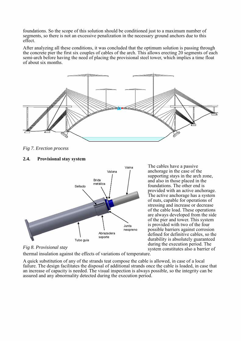
After analyzing all these conditions, it was concluded that the optimum solution is passing through the concrete pier the first six couples of cables of the arch. This allows erecting 20 segments of each semi-arch before having the need of placing the provisional steel tower, which implies a time float of about six months.
2.4. Provisional stay system
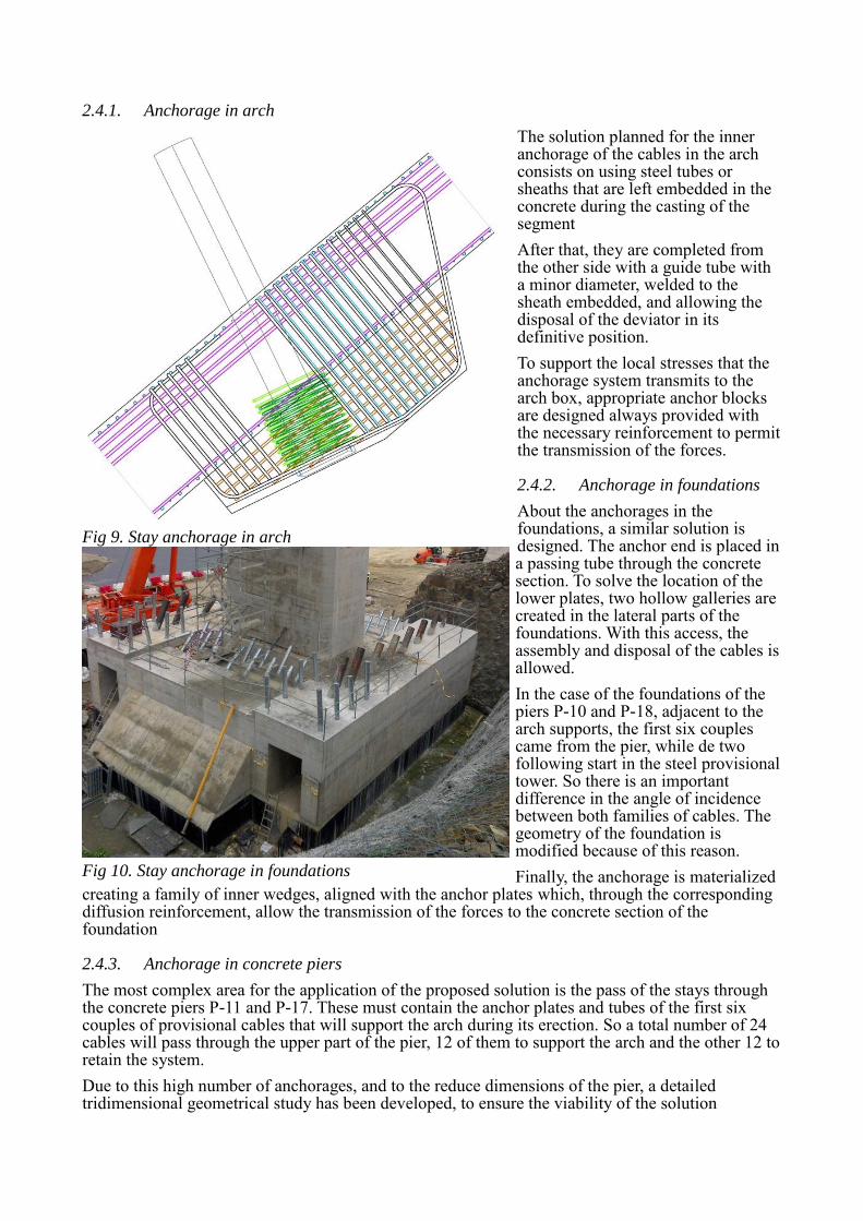
The cables have a passive anchorage in the case of the supporting stays in the arch zone, and also in those placed in the foundations. The other end is provided with an active anchorage. The active anchorage has a system of nuts, capable for operations of stressing and increase or decrease of the cable load. These operations are always developed from the side of the pier and tower. This system is provided with two of the four possible barriers against corrosion defined for definitive cables, so the durability is absolutely guaranteed during the execution period. The system constitutes also a barrier of
thermal insulation against the effects of variations of temperature.
A quick substitution of any of the strands teat compose the cable is allowed, in case of a local failure. The design facilitates the disposal of additional strands once the cable is loaded, in case that an increase of capacity is needed. The visual inspection is always possible, so the integrity can be assured and any abnormality detected during the execution period.
Fig 7. Erection process
Fig 8. Provisional stay
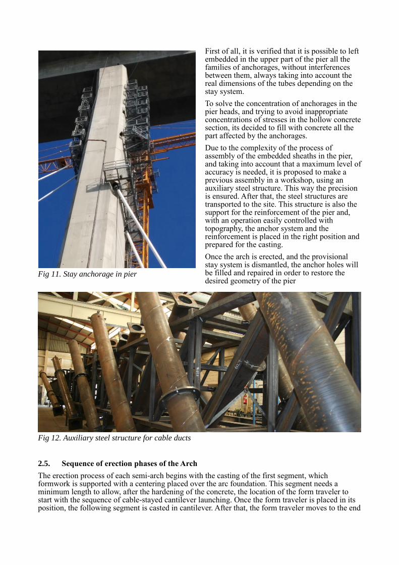
2.4.1. Anchorage in arch
The solution planned for the inner anchorage of the cables in the arch consists on using steel tubes or sheaths that are left embedded in the concrete during the casting of the segment
After that, they are completed from the other side with a guide tube with a minor diameter, welded to the sheath embedded, and allowing the disposal of the deviator in its definitive position.
To support the local stresses that the anchorage system transmits to the arch box, appropriate anchor blocks are designed always provided with the necessary reinforcement to permit the transmission of the forces.
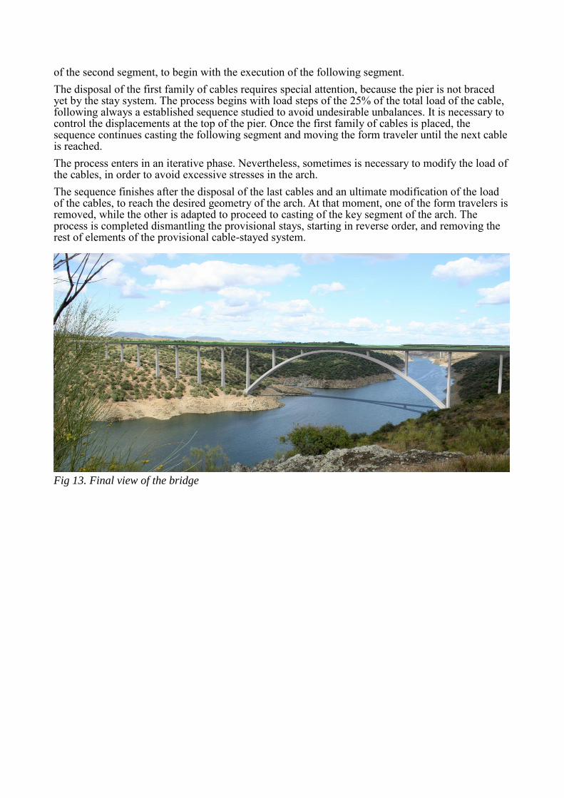
2.4.2. Anchorage in foundations
About the anchorages in the foundations, a similar solution is designed. The anchor end is placed in a passing tube through the concrete section. To solve the location of the lower plates, two hollow galleries are created in the lateral parts of the foundations. With this access, the assembly and disposal of the cables is allowed.
In the case of the foundations of the piers P-10 and P-18, adjacent to the arch supports, the first six couples came from the pier, while de two following start in the steel provisional tower. So there is an important difference in the angle of incidence between both families of cables. The geometry of the foundation is modified because of this reason.
Finally, the anchorage is materialized creating a family of inner wedges, aligned with the anchor plates which, through the corresponding diffusion reinforcement, allow the transmission of the forces to the concrete section of the foundation
2.4.3. Anchorage in concrete piers
The most complex area for the application of the proposed solution is the pass of the stays through the concrete piers P-11 and P-17. These must contain the anchor plates and tubes of the first six couples of provisional cables that will support the arch during its erection. So a total number of 24 cables will pass through the upper part of the pier, 12 of them to support the arch and the other 12 to retain the system.
Due to this high number of anchorages, and to the reduce dimensions of the pier, a detailed tridimensional geometrical study has been developed, to ensure the viability of the solution
Fig 9. Stay anchorage in arch
Fig 10. Stay anchorage in foundations
First of all, it is verified that it is possible to left embedded in the upper part of the pier all the families of anchorages, without interferences between them, always taking into account the real dimensions of the tubes depending on the stay system.
To solve the concentration of anchorages in the pier heads, and trying to avoid inappropriate concentrations of stresses in the hollow concrete section, its decided to fill with concrete all the part affected by the anchorages.
Due to the complexity of the process of assembly of the embedded sheaths in the pier, and taking into account that a maximum level of accuracy is needed, it is proposed to make a previous assembly in a workshop, using an auxiliary steel structure. This way the precision is ensured. After that, the steel structures are transported to the site. This structure is also the support for the reinforcement of the pier and, with an operation easily controlled with topography, the anchor system and the reinforcement is placed in the right position and prepared for the casting.
Once the arch is erected, and the provisional stay system is dismantled, the anchor holes will be filled and repaired in order to restore the desired geometry of the pier
2.5. Sequence of erection phases of the Arch
The erection process of each semi-arch begins with the casting of the first segment, which formwork is supported with a centering placed over the arc foundation. This segment needs a minimum length to allow, after the hardening of the concrete, the location of the form traveler to start with the sequence of cable-stayed cantilever launching. Once the form traveler is placed in its position, the following segment is casted in cantilever. After that, the form traveler moves to the end
Fig 11. Stay anchorage in pier
Fig 12. Auxiliary steel structure for cable ducts
of the second segment, to begin with the execution of the following segment.
The disposal of the first family of cables requires special attention, because the pier is not braced yet by the stay system. The process begins with load steps of the 25% of the total load of the cable, following always a established sequence studied to avoid undesirable unbalances. It is necessary to control the displacements at the top of the pier. Once the first family of cables is placed, the sequence continues casting the following segment and moving the form traveler until the next cable is reached.
The process enters in an iterative phase. Nevertheless, sometimes is necessary to modify the load of the cables, in order to avoid excessive stresses in the arch.
The sequence finishes after the disposal of the last cables and an ultimate modification of the load of the cables, to reach the desired geometry of the arch. At that moment, one of the form travelers is removed, while the other is adapted to proceed to casting of the key segment of the arch. The process is completed dismantling the provisional stays, starting in reverse order, and removing the rest of elements of the provisional cable-stayed system.


![[OpenStack Day in Korea 2015] Track 2-6 - Apache Tajo on Swift](https://static.documents.pub/doc/80x56/55c36f50bb61eb31328b45a7/openstack-day-in-korea-2015-track-2-6-apache-tajo-on-swift.jpg)


