233
CRBIM1002-2015 Railway BIM Data Standard (Version 1.0) Issued on: 2015-12-29 Implemented on: 2016-01-01 China Railway BIM Alliance CRBIM

CRBIM1002-2015
Railway BIM Data Standard
(Version 1.0)
Issued on: 2015-12-29 Implemented on: 2016-01-01
China Railway BIM Alliance CRBIM
Foreword
In order to share information in different application platforms, different participants and
different engineering stages, and to deliver open-format based BIM outcomes to the owners and
industry regulators, this standard is developed. This standard is an extension of IFC4x1 in railway
engineering domain.
This standard covers the following disciplines in railway engineering: alignment, track,
subgrade, bridge, tunnel, station, drainage and geology.
The China Railway BIM Alliance is responsible for the interpretation of this standard. Any
feedback of modification and supplement requirements is welcomed by the China Railway BIM
Alliance.
Editors in chief:
The Third Railway Survey and Design Institute Group Corporation (The 3rd Design
Institute): Sun Shuli, Li Hualiang, Yang Xukun, Yao Fengfeng, Su Lin, Mao Ning, Ai
Shanding, Feng Pei, Feng Shanqun, Yan Dongxu, Fan Dengke, Han Zujie, Qi Chunyu,
Zhao Feifei, Zhang Chen, Wei Yinghong, Zhu Tianhua, Zhu Qingqing, Yu Xingliang, Sun
Haifu, Li Ronghua, Kong Guoliang, Wang KaiJun, Li Zhiji, Chang Cheng, Wu Weifan,
Su Wei, Song Shufeng, Qi Chenglong, Miao Yongkang, Wang Shiqing, Meng Qingyu,
Guo Jianyong, Ma Yongchang, Wang Hao, Liu Zhongjie, Chen Zelian
Tsinghua University: Gu Ming, Liu Yushen, Gao Ge, Zhu Mingjuan, Wu Jiaxing, Lin
Pengpeng, Wu Pengfei
Editors:
China Railway Engineering Management Center: Li Zhiyi, Sheng Liming, Shen
Dongsheng, Liu Yanhong, Wang Wanqi, Chen Liang, Chen Yun, Wang Jiang, Suo Ning,
Li Hui
China Railway First Survey & Design Institute Group CO., LTD. (The 1st Design Institute):
Wen Zhouquan, Li Zhibiao, Wang Wei, Ni Wei, Meng Cunxi, Liu Xingang, Wei Fanghua,
Wang Peng, Zhang YanSheng, Yu Peng, Zhou Fujun, Zheng Liangliang, Xu Xingwang,
Jin Meng, Liu Yanming, Sha Peizhou, Xu Bo, Cheng Fanghui, Zhou Haibo, Liu Lei, Zhu
Tieshuan, Yu Feng, Yang Changhui, Wang Zhaocun, Yan Peng, Wu Wenbin, Luo Wen,
Yang Yuxiu
China Railway Eryuan Engineering Group CO.LTD. (The 2nd Design Institute): Zhang
Xuecai, Zhou Jian, Dong Fengxiang, Zhang Yi, Liu Houqiang, Li Junsong, Ye Mingzhu,
Yang Yongyi, Shao Yan, Chen Gang, Zhu Yongbiao, Wang Yanzhe, Xu Jun, Zheng Yi,
Wu Hualin, Li Liangwei, Liu Dayuan, Zhao Liangliang, Yi Fengfeng, Jin Yongle, Lin
Shaoping, Wang Yiping, Hu Guangchang, Mao Ling, Wang Yimin, Zhang Yao
China Railway SIYUAN Survey & Design Group Co., Ltd. (The 4th Design Institute): Xu
Yonghong, Cao Feng, Peng Xianbao, Han Yuanli, Han Song, Ma Huan, Quan Shunxi, Fu
Jie, Yu Xingsheng, Zhang Jian, Zhao Yueyue, Dai Linfabao, Li Pei, Zhang Xiechong, Xie
Hao, Jiang Daojun, Shi Bibo
China Academy of Railway Sciences: Wang Tongjun, Zhao Youming, Ye YAngsheng,
Luo Qingzhog, Shi Weifeng, Yu Xin, Wang Weidong, Shi Tianyun, Zhang Weijiao, Lu
Wenlong, Cai Degou, Xie Yalong, Zhang Jinchao, Guo Ge, Niu Hongrui, Wang Chao,
CRBIM

Liang Ce, Hao Rui, Wang Tong, Wang Huilin, Shen Haiyan, Feng Yunmei, Zhao Xinxin,
Pan Yongjie, Bai Ping
China Tiesiju Civil Engineering Group Co., Ltd.: Wu Jun, Wang Qinghe, Wang Guoming,
Hu Lei, Wang Buyun
China Construction Communications Engrg. Group Corp. LTD: Wang Yongyi, Liu Wei,
Wen Guowei, Ma Chunquan, Xie Zhongyuan, Sun Xiliang
CRBIM
Contents
Railway BIM Data Standard (Version 1.0) ................................................................................... 1
1.Introduction ....................................................................................................................... 1
1.1 Principle ..................................................................................................................... 1
1.2 Scope ........................................................................................................................... 1
1.3 Purpose ....................................................................................................................... 1
1.4 Normative References ............................................................................................... 1
2.Terms, definitions and abbreviations .............................................................................. 2
2.1 Terms and definitions ................................................................................................ 2
2.2 Abbreviations ............................................................................................................. 2
3.Framework ........................................................................................................................ 2
3.1 Architecture ............................................................................................................... 3
3.2 Railway Engineering Spatial Composition ............................................................. 3
4.Shared Railway Element Schemas ................................................................................... 4
4.1 Shared Types .............................................................................................................. 4
4.1.1 IfcGeoElementComponentTypeEnum ......................................................... 4
4.2 Shared Spatial Structure Elements .......................................................................... 5
4.2.1 IfcCivilStructureElement .............................................................................. 5
4.2.2 IfcRailwayStructureElement ......................................................................... 6
4.2.3 IfcRailway ....................................................................................................... 6
4.3 Shared Components .................................................................................................. 7
4.3.1 IfcCivilElementComponent ........................................................................... 7
4.3.2 IfcRailwayElementComponent ..................................................................... 7
4.3.3 IfcGeoElementComponent ............................................................................ 8
4.4 Shared Property Sets ................................................................................................ 8
4.4.1 Pset_RailwayProject ...................................................................................... 8
4.4.2 Pset_MainTechnicalStandardOfRailway ..................................................... 9
4.4.3 Pset_ConcreteElementGeneral ................................................................... 10
4.4.4 Pset_PrecastConcreteElementFabrication ................................................. 11
4.4.5 Pset_PrecastConcreteElementGeneral ....................................................... 12
4.4.6 Pset_GeologicalCondition ............................................................................ 14
4.4.7 Pset_StandardDrawingNumber .................................................................. 15
4.4.8 Pset_RailwayElementCommon ................................................................... 15
4.4.9 Pset_ANCHOREDBOLT ............................................................................. 16
5. Alignment Schema ............................................................................................................. 16
5.1 Schema Definition ................................................................................................... 16
5.2 Type Definition ........................................................................................................ 19
5.2.1 IfcAlignmentTypeEnum .............................................................................. 19
5.2.2 IfcTransitionCurveTypeEnum .................................................................... 19
5.3 Entity Definition ...................................................................................................... 20
5.3.1 IfcAlignment ................................................................................................. 20
5.3.1.1 Entity definition ................................................................................. 20
5.3.1.2 Attribute definitions .......................................................................... 20
5.3.1.3 EXPRESS specification ..................................................................... 20
CRBIM
5.3.2 IfcAlignment2DHorizontal .......................................................................... 21
5.3.2.1 Entity definition ................................................................................. 21
5.3.2.2 Attribute definitions .......................................................................... 21
5.3.2.3 EXPRESS specification ..................................................................... 22
5.3.3 IfcAlignment2DVertical ............................................................................... 22
5.3.3.1 Entity definition ................................................................................. 22
5.3.3.2 Attribute definitions .......................................................................... 22
5.3.3.3 EXPRESS specification ..................................................................... 22
5.3.4 IfcAlignment2DSegment .............................................................................. 22
5.3.4.1 Entity definition ................................................................................. 22
5.3.4.2 Attribute definitions .......................................................................... 23
5.3.4.3 EXPRESS specification ..................................................................... 23
5.3.5 IfcAlignment2DHorizontalSegment ........................................................... 23
5.3.5.1 Entity definition ................................................................................. 23
5.3.5.2 Attribute definitions .......................................................................... 23
5.3.5.3 EXPRESS specification ..................................................................... 24
5.3.6 IfcAlignment2DVerticalSegment ................................................................ 24
5.3.6.1 Entity definition ................................................................................. 24
5.3.6.2 Attribute definitions .......................................................................... 24
5.3.6.3 EXPRESS specification ..................................................................... 24
5.3.7 IfcCurveSegment2D ..................................................................................... 25
5.3.7.1 Entity definition ................................................................................. 25
5.3.7.2 Attribute definitions .......................................................................... 25
5.3.7.3 EXPRESS specification ..................................................................... 25
5.3.8 IfcLineSegment2D ........................................................................................ 25
5.3.8.1 Entity definition ................................................................................. 25
5.3.8.2 Attribute definitions .......................................................................... 25
5.3.8.3 EXPRESS specification ..................................................................... 25
5.3.9 IfcCircularArcSegment2D ........................................................................... 26
5.3.9.1 Entity definition ................................................................................. 26
5.3.9.2 Attribute definitions .......................................................................... 26
5.3.9.3 EXPRESS specification ..................................................................... 26
5.3.10 IfcTransitionCurve2D ................................................................................ 26
5.3.10.1 Entity definition ............................................................................... 26
5.3.10.2 Attribute definitions ........................................................................ 26
5.3.10.3 EXPRESS specification ................................................................... 27
5.3.11 IfcAlignment2DVerSegLine ....................................................................... 27
5.3.11.1 Entity definition ............................................................................... 27
5.3.11.2 Attribute definitions ........................................................................ 27
5.3.11.3 EXPRESS specification ................................................................... 27
5.3.12 IfcAlignment2DVerSegCircularArc ......................................................... 27
5.3.12.1 Entity definition ............................................................................... 27
5.3.12.2 Attribute definitions ........................................................................ 27
5.3.12.3 EXPRESS specification ................................................................... 27
CRBIM
5.3.13 IfcAlignment2DVerSegParabolicArc ........................................................ 28
5.3.13.1 Entity definition ............................................................................... 28
5.3.13.2 Attribute definitions ........................................................................ 28
5.3.13.3 EXPRESS specification ................................................................... 28
5.3.14 IfcChainageSystem ..................................................................................... 28
5.3.14.1 Entity definition ............................................................................... 29
5.3.14.2 Attribute definitions ........................................................................ 29
5.3.14.3 EXPRESS specification ................................................................... 29
5.3.15 IfcChainageSystemSegment ...................................................................... 29
5.3.15.1 Entity definition ............................................................................... 29
5.3.15.2 Attribute definitions ........................................................................ 30
5.3.15.3 EXPRESS specification ................................................................... 30
5.4 Property Set Definition ........................................................................................... 31
5.4.1 Pset_Alignment ............................................................................................. 31
6.Terrain Schema ............................................................................................................... 31
7.Geology Schema .............................................................................................................. 31
7.1 Schema Definition ................................................................................................... 31
7.1.1 Spatial Structure Elements of Geology....................................................... 32
7.1.2 Physical Elements of Geology ...................................................................... 32
7.2 Type Definition ........................................................................................................ 33
7.2.1 IfcGeologyPartTypeEnum ........................................................................... 33
7.2.2 IfcGeologyTypeEnum .................................................................................. 34
7.2.3 IfcSpecialGeologyTypeEnum ...................................................................... 34
7.2.4 IfcGeologyDisasterTypeEnum .................................................................... 35
7.3 Entity Definition ...................................................................................................... 36
7.3.1 IfcGeologyPart .............................................................................................. 36
7.3.2 IfcGeologyElement ....................................................................................... 36
7.3.3 IfcRockSoilMass ........................................................................................... 36
7.3.4 IfcDrillHole ................................................................................................... 37
7.3.5 IfcDrillHoleLayer ......................................................................................... 37
7.4 Property Set Definition ........................................................................................... 38
7.4.1 Pset_GeologyPart ......................................................................................... 38
7.4.2 Pset_RockSoilMassCommon ....................................................................... 38
7.4.3 Pset_DrillHole ............................................................................................... 39
7.4.4 Pset_RockSoilMassProperty ....................................................................... 39
7.4.5 Pset_SpecialGeology_COLLAPSIBLESOIL ............................................. 39
7.4.6 Pset_SpecialGeology_EXPANSIVESOIL .................................................. 40
7.4.7 Pset_SpecialGeology_FROST ..................................................................... 40
7.4.8 Pset_SpecialGeology_HALOMORPHICSOIL .......................................... 40
7.4.9 Pset_SpecialGeology_POLLUTIONSOIL ................................................. 41
7.4.10 Pset_GeologyDisaster_LANDSLIDE ........................................................ 41
7.4.11 Pset_GeologyDisaster_DEBRISFLOW .................................................... 41
7.4.12 Pset_GeologyDisaster_KARST ................................................................. 41
7.4.13 Pset_GeologyDisaster_GOB ...................................................................... 41
CRBIM
7.4.14 Pset_GeologyDisaster_RADIOACTIVE .................................................. 42
7.4.15 Pset_GeologyDisaster_SANDSTORM ..................................................... 42
7.4.16 Pset_TestParameter.................................................................................... 42
8.Subgrade Schema ............................................................................................................ 43
8.1 Schema Definition ................................................................................................... 43
8.1.1 Spatial Structure Elements of Subgrade .................................................... 45
8.1.2 Physical Elements of Subgrade ................................................................... 47
8.1.3 Element Assemblies of Subgrade ................................................................ 48
8.2 Type Definition ........................................................................................................ 49
8.2.1 IfcSubgradeStructureTypeEnum ................................................................ 49
8.2.2 IfcSubgradeFunctionTypeEnum ................................................................. 49
8.2.3 IfcSubgradeStructurePartTypeEnum ........................................................ 49
8.2.4 IfcSubgradeSlopeProtectionTypeEnum ..................................................... 50
8.2.5 IfcSubgradeRetainingStructureTypeEnum ............................................... 50
8.2.6 IfcSubgradeSubsoilTreatmentTypeEnum .................................................. 51
8.2.7 IfcSubgradeTransitionSectionStructureTypeEnum .................................. 52
8.2.8 IfcSubgradeRetainingElementTypeEnum ................................................. 52
8.2.9 IfcSubgradeFillingWorksTypeEnum .......................................................... 53
8.2.10 IfcSubgradeSlopeProtectionSectionElementTypeEnum ......................... 54
8.2.11 IfcSubgradeSubsoilReinforcementPileElementTypeEnum .................... 55
8.2.12 IfcSubgradeOriginalSubgradeSubsoilReinforcementTypeEnum .......... 55
8.2.13 IfcSubgradeTransitionSectionElementTypeEnum .................................. 56
8.2.14 IfcSubgradeRetainingStructureSectionAssemblyTypeEnum ................ 56
8.2.15 IfcSubgradeSubsoilReinforcementPileAssemblyTypeEnum .................. 57
8.3 Entity Definition ...................................................................................................... 58
8.3.1 IfcSubgradeStructureElement .................................................................... 58
8.3.2 IfcSubgrade ................................................................................................... 58
8.3.3 IfcSubgradeStructurePartElement ............................................................. 59
8.3.4 IfcSubgradeSlopeProtectionElement .......................................................... 60
8.3.5 IfcSubgradeRetainingStructureElement .................................................... 60
8.3.6 IfcSubgradeSubsoilTreatmentElement ...................................................... 62
8.3.7 IfcSubgradeTransitionSectionStructureElement ...................................... 63
8.3.8 IfcSubgradeElement .................................................................................... 63
8.3.9 IfcSubgradeRetainingElement .................................................................... 63
8.3.10 IfcSubgradeFillingWorks .......................................................................... 64
8.3.11 IfcSubgradeSlopeProtectionSectionElement ........................................... 65
8.3.12 IfcSubgradeSubsoilReinforcementPileElement ....................................... 65
8.3.13 IfcOriginalSubgradeSubsoilReinforcement ............................................. 66
8.3.14 IfcSubgradeTransitionSectionElement..................................................... 66
8.3.15 IfcSubgradeElementAssembly .................................................................. 67
8.3.16 IfcSubgradeRetainingStructureSectionAssembly ................................... 67
8.3.17 IfcSubgradeSubsoilReinforcementPileAssembly .................................... 68
8.4 Property Set Definition ........................................................................................... 68
8.4.1 Pset_SubgradeStructurePartElementCommon ......................................... 68
CRBIM
8.4.2 Pset_SubgradeSlopeProtectionElementCommon ..................................... 69
8.4.3 Pset_SubgradeRetainingStructureElementCommon................................ 69
8.4.4 Pset_SubgradeSubsoilTreatmentElementCommon .................................. 69
8.4.5 Pset_REICONRETWALL ........................................................................... 70
8.4.6 Pset_ANCBOLTRETWALL ....................................................................... 70
8.4.7 Pset_EMBANKMENTCUTTING .............................................................. 70
8.4.8 Pset_SubgradeFillingWorksCommon ........................................................ 71
8.4.9 Pset_SubgradeSlopeProtectionSectionElementCommon ......................... 71
8.4.10 Pset_SubgradeSubsoilReinforcementPileElementCommon .................. 71
8.4.11 Pset_OriginalSubgradeSubsoilReinforcementCommon ......................... 72
8.4.12 Pset_GRARETBODY ................................................................................ 72
8.4.13 Pset_BALWEIRETBODY ......................................................................... 72
8.4.14 Pset_CANRETBODY ................................................................................ 73
8.4.15 Pset_COURETBODY ................................................................................ 73
8.4.16 Pset_ANCHORAGEPILE ......................................................................... 73
8.4.17 Pset_RETAININGPLATE ......................................................................... 73
8.4.18 Pset_RIBBEDCOLUMN ........................................................................... 74
8.4.19 Pset_PANEL ............................................................................................... 74
8.4.20 Pset_REIEARRETBODY ......................................................................... 74
8.4.21 Pset_PRECABLEBODY ........................................................................... 75
8.4.22 Pset_REPSUBBASE .................................................................................. 75
8.4.23 Pset_PILECAP ........................................................................................... 75
8.4.24 Pset_PILEBODY ........................................................................................ 75
8.4.25 Pset_COMPACTION ................................................................................. 76
8.4.26 Pset_RAMMED .......................................................................................... 76
8.4.27 Pset_GROUTING ...................................................................................... 76
8.4.28 Pset_TRANSITIONCONE ........................................................................ 77
8.4.29 Pset_FOUNDATIONBACKFILLINGSOIL ............................................ 77
8.4.30 Pset_NONSANDCONPERPLATE ........................................................... 77
8.4.31 Pset_REPLACEMENTSOIL .................................................................... 77
9.Bridge Schema ................................................................................................................. 78
9.1 Schema Definition ................................................................................................... 78
9.1.1 Spatial Structure Elements of Bridge ......................................................... 80
9.1.2 Physical Elements of Bridge ........................................................................ 81
9.1.3 Element Assemblies of Bridge ..................................................................... 84
9.1.4 Others ............................................................................................................ 85
9.2 Type Definition ........................................................................................................ 86
9.2.1 IfcBridgeStructureTypeEnum..................................................................... 86
9.2.2 IfcBridgeStructurePartTypeEnum ............................................................. 86
9.2.3 IfcBridgeMemberTypeEnum ...................................................................... 87
9.2.4 IfcBridgeStiffeningRibTypeEnum .............................................................. 87
9.2.5 IfcBridgeSlabTypeEnum ............................................................................. 88
9.2.6 IfcBridgeGirderSegmentTypeEnum........................................................... 88
9.2.7 IfcBridgeGearBlockTypeEnum .................................................................. 88
CRBIM

9.2.8 IfcBridgeBedStoneTypeEnum ..................................................................... 89
9.2.9 IfcBridgePierSegmentTypeEnum ............................................................... 89
9.2.10 IfcBridgeAbutmentSegmentTypeEnum ................................................... 89
9.2.11 IfcBridgePylonSegmentTypeEnum ........................................................... 90
9.2.12 IfcBridgeArchSegmentTypeEnum ............................................................ 90
9.2.13 IfcBridgeArchfootTypeEnum .................................................................... 91
9.2.14 IfcBridgeStandColumnTypeEnum ........................................................... 91
9.2.15 IfcBridgeSuspenderTypeEnum ................................................................. 91
9.2.16 IfcBridgeCableTypeEnum ......................................................................... 91
9.2.17 IfcBridgeSuspendedTendonTypeEnum .................................................... 92
9.2.18 IfcBridgeBearingTypeEnum ..................................................................... 92
9.2.19 IfcBridgeExpansionInstallationTypeEnum ............................................. 92
9.2.20 IfcBridgeProtectingWallTypeEnum ......................................................... 93
9.2.21 IfcBridgeFrameSegmentTypeEnum ......................................................... 93
9.2.22 IfcBridgeWingWallTypeEnum .................................................................. 93
9.2.23 IfcBridgeCulvertSegmentTypeEnum ....................................................... 94
9.2.24 IfcBridgeHatStoneTypeEnum ................................................................... 94
9.2.25 IfcBridgeCopingTypeEnum ...................................................................... 94
9.2.26 IfcBridgeEmbeddedPartsFoundationTypeEnum .................................... 94
9.2.27 IfcBridgeRefugePlatformTypeEnum ........................................................ 95
9.2.28 IfcBridgeTrussTypeEnum ......................................................................... 95
9.2.29 IfcBridgeJointTypeEnum .......................................................................... 95
9.2.30 IfcBeamFallingPreventionDeviceTypeEnum ........................................... 96
9.2.31 IfcCrossBraceTypeEnum ........................................................................... 96
9.3 Entity Definition ...................................................................................................... 97
9.3.1 IfcBridgeStructureElement ......................................................................... 97
9.3.2 IfcBridge ....................................................................................................... 97
9.3.3 IfcBridgePart .............................................................................................. 101
9.3.4 IfcBridgeElement ....................................................................................... 103
9.3.5 IfcBridgeMember ....................................................................................... 103
9.3.6 IfcBridgeStiffeningRib ............................................................................... 104
9.3.7 IfcBridgeSlab .............................................................................................. 104
9.3.8 IfcBridgeGirderSegment ........................................................................... 105
9.3.9 IfcBridgeGearBlock ................................................................................... 105
9.3.10 IfcBridgeBedstone .................................................................................... 106
9.3.11 IfcBridgePierSegment .............................................................................. 106
9.3.12 IfcBridgeAbutmentSegment .................................................................... 106
9.3.13 IfcBridgePylonSegment ........................................................................... 107
9.3.14 IfcBridgeArchSegment ............................................................................ 107
9.3.15 IfcBridgeArchFoot ................................................................................... 107
9.3.16 IfcBridgeStandColumn ............................................................................ 108
9.3.17 IfcBridgeSuspender .................................................................................. 108
9.3.18 IfcBridgeCable .......................................................................................... 109
9.3.19 IfcBridgeSuspendedTendon .................................................................... 109
CRBIM
9.3.20 IfcBridgeBearing ...................................................................................... 109
9.3.21 IfcBridgeExpansionInstallation .............................................................. 110
9.3.22 IfcBridgeProtectingWall .......................................................................... 110
9.3.23 IfcFrameSegment ..................................................................................... 111
9.3.24 IfcBridgeWingWall .................................................................................. 111
9.3.25 IfcBridgeCulvertSegment ........................................................................ 111
9.3.26 IfcBridgeHatStone .................................................................................... 112
9.3.27 IfcBridgeCoping ....................................................................................... 112
9.3.28 IfcBridgeEmbeddedPartsFoundation .................................................... 112
9.3.29 IfcBridgeRefugePlatform ........................................................................ 113
9.3.30 IfcBridgeElementAssembly ..................................................................... 113
9.3.31 IfcBridgeTruss .......................................................................................... 113
9.3.32 IfcBridgeJoint ........................................................................................... 114
9.3.33 IfcBeamFallingPreventionDevice ............................................................ 115
9.3.34 IfcCrossBrace ........................................................................................... 115
9.4 Property Set Definition ......................................................................................... 116
9.4.1 Pset_BridgeCommon ................................................................................. 116
9.4.2 Pset_TechnicalStandard ............................................................................ 116
9.4.3 Pset_TechnicalIndex ................................................................................... 117
9.4.4 Pset_Bellow ................................................................................................. 118
9.4.5 Pset_BridgeCable ....................................................................................... 118
9.4.6 Pset_ArchBridge......................................................................................... 118
9.4.7 Pset_RigidBridge ........................................................................................ 119
9.4.8 Pset_Gird .................................................................................................... 119
9.4.9 Pset_BridgePier .......................................................................................... 120
9.4.10 Pset_PileCommon .................................................................................... 120
9.4.11 Pset_Abutment .......................................................................................... 120
9.4.12 Pset_Culvert.............................................................................................. 120
9.4.13 Pset_BridgeBearing .................................................................................. 121
9.4.14 Pset_BridgeExpansionInstallation .......................................................... 121
10.Tunnel Schema ............................................................................................................ 122
10.1 Schema Definition ............................................................................................... 122
10.1.1 Spatial Structure Elements of Tunnel ..................................................... 123
10.1.2 Physical Elements of Tunnel .................................................................... 124
10.2 Type Definition .................................................................................................... 126
10.2.1 IfcTunnelTypeEnum ................................................................................ 126
10.2.2 IfcTunnelFunctionTypeEnum ................................................................. 127
10.2.3 IfcTunnelPartTypeEnum ......................................................................... 128
10.2.4 IfcAdvanceSupportTypeEnum................................................................ 128
10.2.5 IfcPrimarySupportTypeEnum ................................................................ 129
10.2.6 IfcSystemAncherBoltTypeEnum ............................................................ 129
10.2.7 IfcSystemSteelFrameTypeEnum ............................................................. 129
10.2.8 IfcInitialSupportShotcreteTypeEnum .................................................... 129
10.2.9 IfcTunnelLiningTypeEnum ..................................................................... 130
CRBIM
10.2.10 IfcPortalStructureTypeEnum ............................................................... 130
10.2.11 IfcInvertFillingTypeEnum ..................................................................... 131
10.2.12 IfcWaterproofLayerTypeEnum ............................................................ 131
10.2.13 IfcLevelingBlanketTypeEnum .............................................................. 131
10.2.14 IfcProtectiveLayerTypeEnum ............................................................... 132
10.2.15 IfcProtectiveArchTypeEnum ................................................................. 132
10.2.16 IfcTemporarySupportTypeEnum ......................................................... 132
10.3 Entity Definition .................................................................................................. 133
10.3.1 IfcTunnelStructureElement ..................................................................... 133
10.3.2 IfcTunnel ................................................................................................... 133
10.3.3 IfcTunnelPart ............................................................................................ 134
10.3.4 IfcTunnelElement ..................................................................................... 135
10.3.5 IfcTunnelAdvanceSupport ...................................................................... 136
10.3.6 IfcTunnelPrimarySupport ....................................................................... 136
10.3.7 IfcSystemAncherBolt ............................................................................... 137
10.3.8 IfcSystemSteelFrame ............................................................................... 137
10.3.9 IfcInitialSupportShotcrete ....................................................................... 138
10.3.10 IfcTunnelLiningStructure ...................................................................... 138
10.3.11 IfcTunnelPortalStructure ....................................................................... 139
10.3.12 IfcTunnelInvertFilling............................................................................ 140
10.3.13 IfcWaterproofLayer ............................................................................... 140
10.3.14 IfcLevelingBlanket ................................................................................. 141
10.3.15 IfcProtectiveLayer .................................................................................. 141
10.3.16 IfcTemporarySupport ............................................................................ 142
10.3.17 IfcProtectiveArch ................................................................................... 142
10.4 Property Set Definition ....................................................................................... 143
10.4.1 Pset_TunnelCommon ............................................................................... 143
10.4.2 Pset_PortalCommon ................................................................................ 143
10.4.3 Pset_Open-cutTunnelCommon ............................................................... 144
10.4.4 Pset_Under-cutTunnelCommon .............................................................. 144
10.4.5 Pset_TunnelChamberCommon ............................................................... 144
10.4.6 Pset_ShedTunnelCommon ....................................................................... 145
10.4.7 Pset_TunnelAdvanceSupportCommon .................................................. 145
10.4.8 Pset_TunnelPrimarySupportCommon ................................................... 146
10.4.9 Pset_SystemAncherBoltCommon ........................................................... 146
10.4.10 Pset_SystemSteelArchCommon ............................................................ 147
10.4.11 Pset_InitialSupportShotcreteCommon ................................................. 147
10.4.12 Pset_TunnelLiningCommon .................................................................. 147
10.4.13 Pset_WaterproofLayerCommon ........................................................... 148
10.4.14 Pset_LevelingBlanketCommon ............................................................. 148
10.4.15 Pset_ProtectiveLayerCommon .............................................................. 148
11.Drainage Schema ......................................................................................................... 149
11.1 Schema Definition................................................................................................ 149
11.2 Distribution System Definition ........................................................................... 149
CRBIM
11.3 Drainage Segment Definition.............................................................................. 150
11.4 Chamber Facility ................................................................................................. 151
12.Track Schema .............................................................................................................. 151
12.1 Schema Definition ............................................................................................... 151
12.1.1 Spatial Structure Elements of Track ...................................................... 152
12.1.2 Physical Elements of Track ..................................................................... 153
12.1.3 Element Assemblies of Track ................................................................... 156
12.1.4 Element Components of Track ................................................................ 156
12.1.5 Other Element Components .................................................................... 157
12.2 Type Definition .................................................................................................... 158
12.2.1 IfcTrackTypeEnum .................................................................................. 158
12.2.2 IfcTrackRouteDirectionTypeEnum ........................................................ 159
12.2.3 IfcTrackRouteFunctionTypeEnum ......................................................... 159
12.2.4 IfcTrackPartStructureTypeEnum .......................................................... 160
12.2.5 IfcTrackPartFunctionTypeEnum ........................................................... 160
12.2.6 IfcTrackRailTypeEnum ........................................................................... 161
12.2.7 IfcTrackFasteningElasticityTypeEnum .................................................. 161
12.2.8 IfcTrackFasteningStructureTypeEnum ................................................. 161
12.2.9 IfcTrackSleeperTypeEnum ...................................................................... 162
12.2.10 IfcTrackSlabTypeEnum ......................................................................... 163
12.2.11 IfcTrackConcreteSlabTypeEnum.......................................................... 163
12.2.12 IfcTrackIsolationLayerTypeEnum ....................................................... 163
12.2.13 IfcTrackElasticCushionTypeEnum ....................................................... 164
12.2.14 IfcTrackAdjustmentlayerTypeEnum ................................................... 164
12.2.15 IfcTrackBaseTypeEnum ........................................................................ 164
12.2.16 IfcTrackTurnoutTypeEnum .................................................................. 165
12.2.17 IfcTrackBallastLayerTypeEnum .......................................................... 165
12.2.18 IfcTrackExpansionJointTypeEnum ...................................................... 166
12.2.19 IfcBallastBedTypeEnum ........................................................................ 166
12.2.20 IfcTrackPanelTypeEnum ....................................................................... 166
12.2.21 IfcTrackRailJointTypeEnum................................................................. 167
12.2.22 IfcTrackStrengtheningEquipmentTypeEnum ..................................... 167
12.2.23 IfcTrackAccessoryEquipmentTypeEnum ............................................ 168
12.2.24 IfcEarthingTerminalTypeEnum ........................................................... 168
12.3 Entity Definition .................................................................................................. 169
12.3.1 IfcTrack ..................................................................................................... 169
12.3.2 IfcTrackPart ............................................................................................. 170
12.3.3 IfcTrackElement ....................................................................................... 171
12.3.4 IfcTrackRail .............................................................................................. 171
12.3.5 IfcTrackFastening .................................................................................... 172
12.3.6 IfcTrackSleeper ........................................................................................ 172
12.3.7 IfcTrackSlab ............................................................................................. 173
12.3.8 IfcTrackConcreteSlab .............................................................................. 174
12.3.9 IfcTrackIsolationLayer ............................................................................ 174
CRBIM
12.3.10 IfcTrackElasticCushion ......................................................................... 175
12.3.11 IfcTrackAdjustmentLayer ..................................................................... 175
12.3.12 IfcTrackBase ........................................................................................... 176
12.3.13 IfcTrackTurnout ..................................................................................... 176
12.3.14 IfcTrackBallastLayer ............................................................................. 177
12.3.15 IfcTrackExpansionJoint ........................................................................ 177
12.3.16 IfcRailwayAssembly ............................................................................... 178
12.3.17 IfcBallastBed ........................................................................................... 178
12.3.18 IfcTrackPanel ......................................................................................... 178
12.3.19 IfcTrackElementComponent ................................................................. 179
12.3.20 IfcTrackRailJoint ................................................................................... 179
12.3.21 IfcTrackStrengtheningEquipment ........................................................ 180
12.3.22 IfcTrackAccessoryEquipment ............................................................... 180
12.3.23 IfcEarthingTerminal .............................................................................. 181
12.4 Property Set Definition ....................................................................................... 181
12.4.1 Pset_TrackCommon ................................................................................. 181
12.4.2 Pset_TrackPartCommon ......................................................................... 182
12.4.3 Pset_RailCommon .................................................................................... 183
12.4.4 Pset_TrackFasteningCommon ................................................................ 184
12.4.5 Pset_TrackSleeperCommon .................................................................... 185
12.4.6 Pset_TrackSlabCommon ......................................................................... 185
12.4.7 Pset_TrackIsolationLayerCommon ........................................................ 186
12.4.8 Pset_TrackElasticCushionCommon ....................................................... 186
12.4.9 Pset_TrackAdjustmentlayerCommon .................................................... 187
12.4.10 Pset_TrackBaseCommon ....................................................................... 187
12.4.11 Pset_TrackBallastLayerCommon ......................................................... 188
12.4.12 Pset_TrackExpansionJointCommon .................................................... 188
12.4.13 Pset_TrackPanelCommon ..................................................................... 189
12.4.14 Pset_TurnoutCommon ........................................................................... 189
12.4.15 Pset_RailJointFasteningCommon ......................................................... 191
12.4.16 Pset_RailCompromisingJointCommon ................................................ 191
12.4.17 Pset_RailInsulatedJointCommon ......................................................... 191
12.4.18 Pset_RailWeldedJointCommon ............................................................ 192
12.4.19 Pset_RailConductiveJointCommon ...................................................... 192
12.4.20 Pset_RailUnchangeableJointCommon ................................................. 193
12.4.21 Pset_TrackStrengtheningEquipmentCommon .................................... 193
12.4.22 Pset_TrackAccessoryEquipmentCommon ........................................... 194
12.4.23 Pset_EarthingTerminalCommon .......................................................... 194
13.Station Schema ............................................................................................................ 194
13.1 Schema Definition ............................................................................................... 194
13.1.1 Spatial Structure Elements of Station .................................................... 195
13.1.2 Physical Elements in Station Schema ..................................................... 196
13.2 Type Definition .................................................................................................... 197
13.2.1 IfcRailwayTerminalTypeEnum ............................................................... 197
CRBIM
13.2.2 IfcRailwayTerminalFeatureTypeEnum .................................................. 198
13.2.3 IfcRailwayStationTypeEnum .................................................................. 199
13.2.4 IfcRailwayStationFeatureTypeEnum ..................................................... 199
13.2.5 IfcRailwayStationFormTypeEnum ......................................................... 200
13.2.6 IfcRailwayStationGradeTypeEnum ....................................................... 200
13.2.7 IfcRailwayPlatformTypeEnum ............................................................... 201
13.2.8 IfcRailwayPlatformPositionTypeEnum ................................................. 201
13.2.9 IfcRailwaySignalTypeEnum .................................................................... 202
13.2.10 IfcRailwayClearancePostTypeEnum .................................................... 203
13.2.11 IfcRailwaySpeedReducerTypeEnum .................................................... 203
13.2.12 IfcRailwayRetarderTypeEnum ............................................................. 203
13.2.13 IfcRailwayDenoterTypeEnum ............................................................... 204
13.2.14 IfcRailwayCarBumperTypeEnum ........................................................ 205
13.2.15 IfcRailwayCarStopperTypeEnum ........................................................ 205
13.2.16 IfcRailwayCarStopperPostionTypeEnum ............................................ 205
13.2.17 IfcRailwayPlatformWallTypeEnum ..................................................... 206
13.2.18 IfcRailwayFlatAisleTypeEnum ............................................................. 206
13.2.19 IfcRailwayWagonScaleTypeEnum ........................................................ 207
13.2.20 IfcRailwayDeflectionInstrumentTypeEnum ........................................ 207
13.2.21 IfcRailwayIronShoeRemovingTypeEnum ........................................... 207
13.2.22 IfcRailwayStopDeviceTypeEnum ......................................................... 208
13.2.23 IfcRailwayStopRetarderTypeEnum ..................................................... 208
13.2.24 IfcRailwayIronShoeTypeEnum ............................................................. 208
13.3 Entity Definition .................................................................................................. 209
13.3.1 IfcRailwayTerminal.................................................................................. 209
13.3.2 IfcRailwayStation ..................................................................................... 209
13.3.3 IfcRailwayPlatform .................................................................................. 210
13.3.4 IfcRailwaySignalDevice ........................................................................... 211
13.3.5 IfcRailwaySignal ...................................................................................... 211
13.3.6 IfcRailwayClearancePost ......................................................................... 211
13.3.7 IfcRailwaySpeedControlDevice .............................................................. 212
13.3.8 IfcRailwaySpeedReducer ......................................................................... 212
13.3.9 IfcRailwayRetarder .................................................................................. 212
13.3.10 IfcRailwayDenoterDevice ...................................................................... 212
13.3.11 IfcRailwaySafetyDevice ......................................................................... 213
13.3.12 IfcRailwayCarBumper ........................................................................... 213
13.3.13 IfcRailwayCarStopper ........................................................................... 213
13.3.14 IfcRailwayIronShoe ............................................................................... 214
13.3.15 IfcRailwayStopRetarde .......................................................................... 214
13.3.16 IfcRailwayStopDevice ............................................................................ 214
13.3.17 IfcRailwayIronShoeRemoving .............................................................. 214
13.3.18 IfcRailwayPlatformWall ........................................................................ 215
13.3.19 IfcRailwayFlatAisle ................................................................................ 215
13.3.20 IfcRailwayMechanicalEquipment ........................................................ 215
CRBIM

13.3.21 IfcRailwayWagonScale .......................................................................... 216
13.3.22 IfcRailwayTruckScale ............................................................................ 216
13.3.23 IfcRailwayDeflectionInstrument ........................................................... 216
13.4 Property Set Definition ....................................................................................... 217
13.4.1 Pset_StationCommon ............................................................................... 217
13.4.2 Pset_FlatAisleCommon ............................................................................ 217
13.4.3 Pset_SignalCommon ................................................................................ 217
14.Others ........................................................................................................................... 218
14. 1 Cable Slot ............................................................................................................ 218
CRBIM

1
Railway BIM Data Standard
(Version 1.0)
1.Introduction
1.1 Principle
The development of the standard follows the following principles:
1) "Compatible principle". To achieve the highest compatibility with existing
buildingSMART IFC (Industry Foundation Classes) standards and its ongoing extension work.
2) "Portable principle". The proposed standard only stipulates the basic data model of the
railway domain. The elements in the model can be used in a variety of technical platforms with
multiple coding ways.
3) "Abstract principle". To define the minimum entity set which are most widely understood
and used.
4) "Extendable principle". The specific information about the railway engineering can be
defined in various information classification standard of different country, regions respectively.
5) "Selectivity principle". Any element defined in this standard is optional to be used in
information exchange and storage.
6) "Repeatable principle". Any element defined in this standard is repeatable to be used in
data exchange and storage.
7) "Usability principle". The proposed standard is usable for both the human readability and
machine readability to achieve the interoperability between software tools.
1.2 Scope
This standard currently covers the following disciplines in railway engineering: alignment,
track, subgrade, bridge, tunnel, station, drainage and geology.
1.3 Purpose
This standard applies to the development of Railway BIM Implementation Standard, the
development of Railway BIM software and related Railway BIM research.
1.4 Normative References
The following referenced documents are indispensable for the application of this document.
1) GB/T 16656.1-2008, Industrial automation systems and integration - Product data
representation and exchange - Part 1: Overview and fundamental principles. (ISO 10303-1: 1994)
2) GB/T 16656.11-2010, Industrial automation systems and integration - Product data
representation and exchange - Part 11: Description methods: The EXPRESS language reference
manual. (ISO 10303-11: 2004)
3) GB/T 16656.21-2008, Industrial automation systems and integration - Product data
CRBIM

2
representation and exchange - Part 21: Implementation methods: Clear text encoding of the
exchange structure. (ISO 10303-21: 2002)
4) GB/T 25507-2010, Industry foundation classes platform. (ISO 16739: 2013)
5) buildingSMART Industry Foundation Classes IFC4x1
6) buildingSMART Industry Foundation Classes IFC4x1 Alignment Extension
2.Terms, definitions and abbreviations
2.1 Terms and definitions
Entity: class of information defined by common attributes and constraints
Attribute: unit of information within an entity, defined by a particular type or reference to a
particular entity
Direct attribute: unit of information directly describing entity characteristics
Inverse attribute: unit of information defining queries for obtaining related data and enforcing
referential integrity
Derived attribute: unit of information computed from other values using an expression defined
in this schema
Property set: unit of information containing a set of properties
Schema: the definition of the structure to organize data for storage, exchange and sharing, using
a formal language
Information model: an abstract semantic representation of concepts and relationships in a
certain domain
Spatial structure element: the generalization of all spatial elements that might be used to define
a spatial structure
Spatial composition: the composition relationship between the part and the whole of the spatial
structure elements
Spatial decomposition: the decomposition relationship between the whole and the parts of the
spatial structure elements.
Spatial containment: the relationship of a spatial structure element containing the physical
elements
Contained in spatial structure: the relationship of physical elements being contained within a
spatial structure element.
Entity composition: an aggregation relationship where the element is part of another composite
element
EXPRESS-G: a graphical modeling notation, used to identify classes, the data attributes of
classes and the relationships that exist between classes
2.2 Abbreviations
AEC/FM Architecture, Engineering, Construction and Facilities Management
BIM Building Information Modeling
IFC Industry Foundation Classes
HVAC Heating, Ventilation and Air Conditioning
XML Extensible Markup Language
3.Framework
CRBIM
3
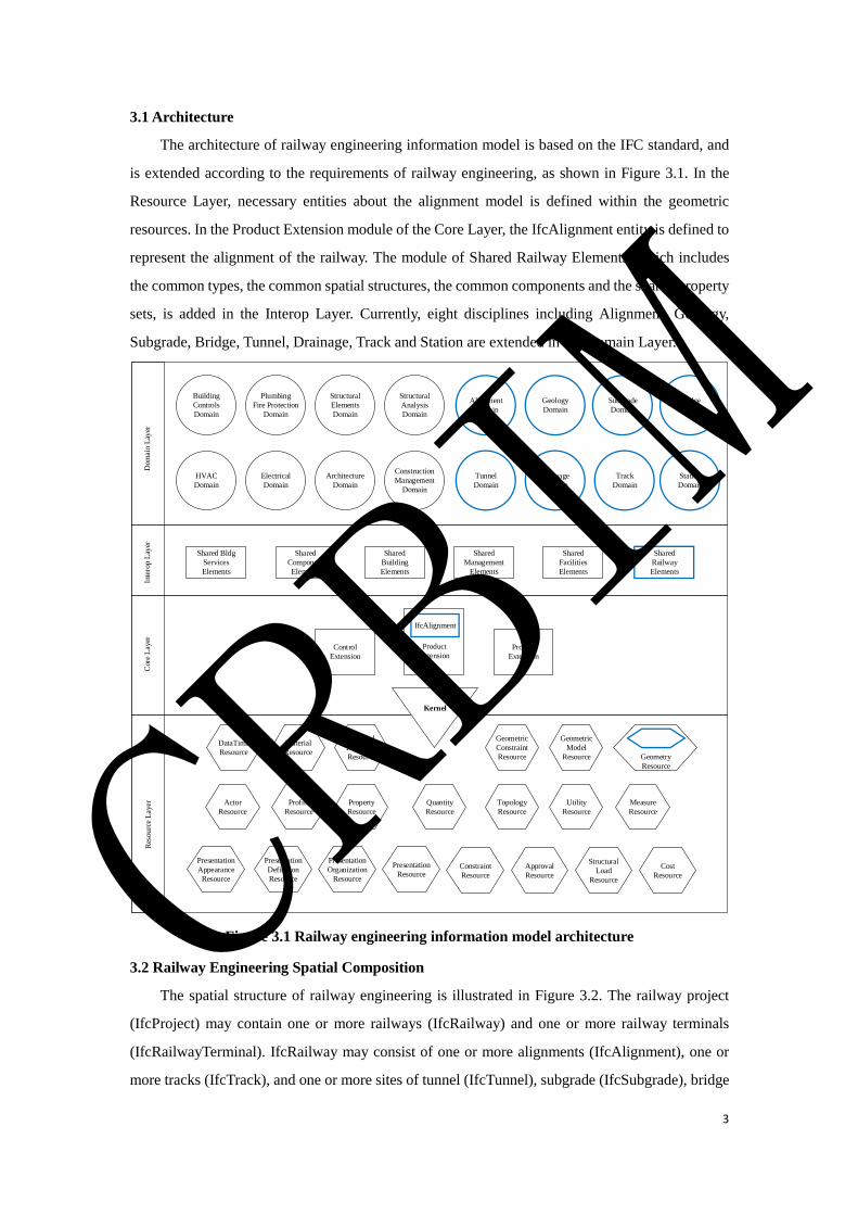
3.1 Architecture
The architecture of railway engineering information model is based on the IFC standard, and
is extended according to the requirements of railway engineering, as shown in Figure 3.1. In the
Resource Layer, necessary entities about the alignment model is defined within the geometric
resources. In the Product Extension module of the Core Layer, the IfcAlignment entity is defined to
represent the alignment of the railway. The module of Shared Railway Elements, which includes
the common types, the common spatial structures, the common components and the shared property
sets, is added in the Interop Layer. Currently, eight disciplines including Alignment, Geology,
Subgrade, Bridge, Tunnel, Drainage, Track and Station are extended in the Domain Layer.
Alignment
Domain
Geology
Domain
Subgrade
Domain
Tunnel
Domain
Drainage
Domain
Track
Domain
Dom
ain
Lay
erIn
tero
p L
ayer
Core
Layer
Res
ou
rce L
ayer
Shared
Component
Elements
Shared
Building
Elements
Shared
Management
Elements
Shared Bldg
Services
Elements
DataTime
Resource
Material
Resource
External
Reference
Resource
Geometric
Constraint
Resource
Profile
Resource
Property
Resource
Quantity
Resource
Topology
Resource
Geometric
Model
Resource
Utility
Resource
Geometry
Resource
Measure
Resource
Actor
Resource
Presentation
Appearance
Resource
Presentation
Definition
Resource
Presentation
Organization
Resource
Presentation
ResourceConstraint
Resource
Approval
Resource
Structural
Load
Resource
Cost
Resource
Kernel
Control
Extension
Product
ExtensionProcess
Extension
Shared
Facilities
Elements
Building
Controls
Domain
Plumbing
Fire Protection
Domain
Structural
Elements
Domain
Structural
Analysis
Domain
HVAC
Domain
Electrical
Domain
Architecture
Domain
Construction
Management
Domain
Shared
Railway
Elements
IfcAlignment
Bridge
Domain
Station
Domain
Figure 3.1 Railway engineering information model architecture
3.2 Railway Engineering Spatial Composition
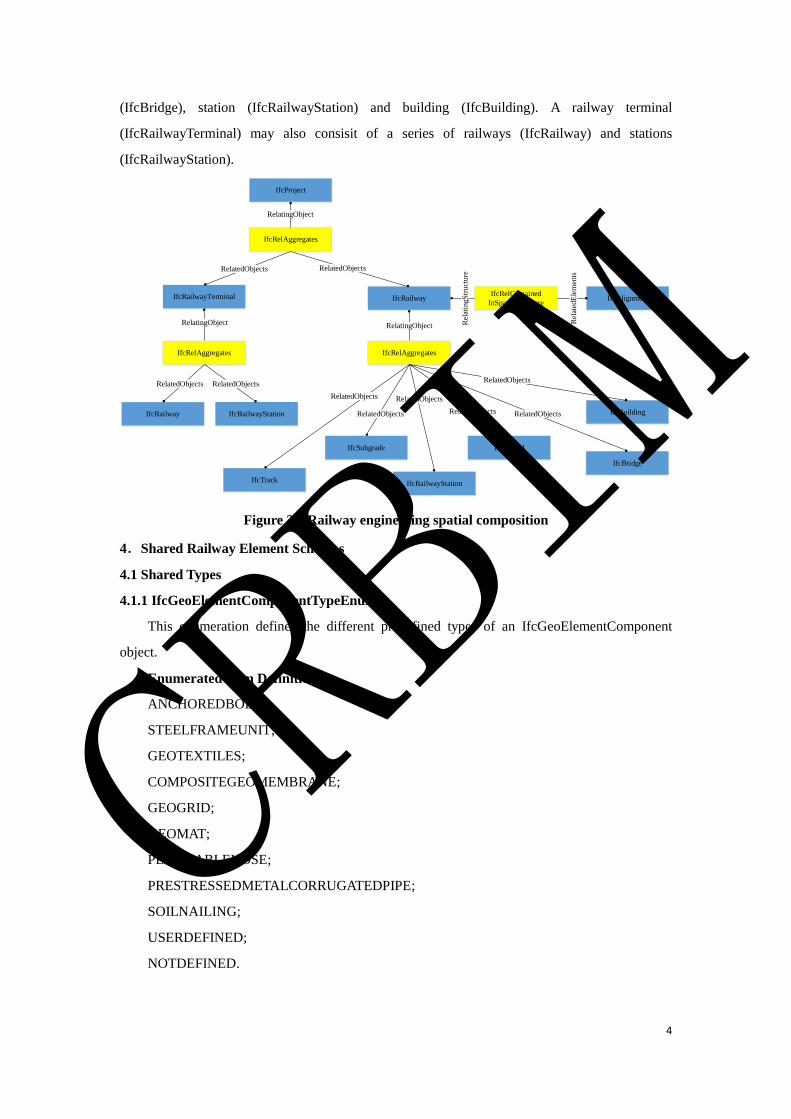
The spatial structure of railway engineering is illustrated in Figure 3.2. The railway project
(IfcProject) may contain one or more railways (IfcRailway) and one or more railway terminals
(IfcRailwayTerminal). IfcRailway may consist of one or more alignments (IfcAlignment), one or
more tracks (IfcTrack), and one or more sites of tunnel (IfcTunnel), subgrade (IfcSubgrade), bridge
CRBIM
4
(IfcBridge), station (IfcRailwayStation) and building (IfcBuilding). A railway terminal
(IfcRailwayTerminal) may also consisit of a series of railways (IfcRailway) and stations
(IfcRailwayStation).
Figure 3.2 Railway engineering spatial composition
4.Shared Railway Element Schemas
4.1 Shared Types
4.1.1 IfcGeoElementComponentTypeEnum
This enumeration defines the different predefined types of an IfcGeoElementComponent
object.
Enumerated Item Definitions:
ANCHOREDBOLT;
STEELFRAMEUNIT;
GEOTEXTILES;
COMPOSITEGEOMEMBRANE;
GEOGRID;
GEOMAT;
PERMEABLEHOSE;
PRESTRESSEDMETALCORRUGATEDPIPE;
SOILNAILING;
USERDEFINED;
NOTDEFINED.
IfcRailway
IfcRailwayTerminal
IfcBridge
IfcProject
IfcRailway
IfcRelAggregates
RelatingObject
RelatedObjects
IfcAlignment
RelatingObject
IfcRelAggregates
IfcRelContained
InSpatialStructure
IfcRailwayStationIfcTrack
IfcTunnel
RelatedObjects
IfcSubgrade
RelatedObjects
Rel
atin
gS
tru
cture
Rel
ated
Ele
men
ts
IfcRailwayStation
RelatedObjects
IfcRelAggregates
RelatedObjects
RelatingObject
RelatedObjects
RelatedObjects
RelatedObjects
IfcBuildingRelatedObjects
RelatedObjects
CRBIM
5
EXPRESS Specification:
TYPE IfcGeoElementComponentTypeEnum = ENUMERATION OF
(ANCHOREDBOLT
,STEELFRAMEUNIT
,GEOTEXTILES
,COMPOSITEGEOMEMBRANE
,GEOGRID
,GEOMAT
,PERMEABLEHOSE
,PRESTRESSEDMETALCORRUGATEDPIPE
,SOILNAILING
,USERDEFINED
,NOTDEFINED);
END_TYPE;
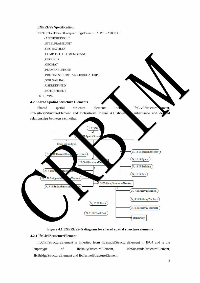
4.2 Shared Spatial Structure Elements
Shared spatial structure elements include IfcCivilStructureElement,
IfcRailwayStructureElement and IfcRailway. Figure 4.1 shows the inheritance and derived
relationships between each other.
Figure 4.1 EXPRESS-G diagram for shared spatial structure elements
4.2.1 IfcCivilStructureElement
IfcCivilStructureElement is inherited from IfcSpatialStructureElement in IFC4 and is the
supertype of IfcRailyStructureElement, IfcSubgradeStructureElement,
IfcBridgeStructureElement and IfcTunnelStructureElement.
CRBIM
6
EXPRESS Specification:
ENTITY IfcCivilStructureElement
SUPERTYPE OF (ONEOF
(IfcRailwayStructureElement
,IfcSubgradeStructureElement
,IfcBridgeStructureElement
,IfcTunnelStructureElement))
SUBTYPE OF (IfcSpatialStructureElement);
END_ENTITY;
4.2.2 IfcRailwayStructureElement
IfcRailwayStructureElement is inherited from IfcCivilStructureElement and is the supertype
of IfcRailway, IfcTrack, IfcTrackPart, IfcRailwayTerminal, IfcRailwayStation and
IfcRailwayPlatform.
EXPRESS Specification:
ENTITY IfcRailwayStructureElement
SUPERTYPE OF (ONEOF
(IfcRailway, IfcTrack, IfcTrackPart,
IfcRailwayTerminal, IfcRailwayStation, IfcRailwayPlatform))
SUBTYPE OF (IfcCivilStructureElement);
END_ENTITY;
4.2.3 IfcRailway
IfcRailway is used to define one railway line. Usually, the railway line, which is named
independently, non-parallel and requires independent engineering quantity statistics, is appropriate
to be defined as an IfcRailway object. An IfcRailway object may contain one, two or more center
lines of railway and multiple IfcTrack objects, IfcSubgrade objects, IfcBridge objects, IfcTunnel
objects, IfcRailwayStation objects and IfcBuilding objects.
Table 4.1 IfcRailway spatial decomposition
Spatial Parts Description
IfcTrack An IfcRailway object may contain multiple IfcTrack objects.
IfcSubgrade An IfcRailway object may contain multiple IfcSubgrade objects.
IfcBridge An IfcRailway object may contain multiple IfcBridge objects.
IfcTunnel An IfcRailway object may contain multiple IfcTunnel objects.
IfcRailwayStation An IfcRailway object may contain multiple IfcRailwayStation objects.
IfcBuilding An IfcRailway object may contain multiple IfcBuilding objects.
Table 4.2 IfcRailway spatial containment
Contained Entities Description
IfcElement Physical elements can be contained in IfcRailway, but generally should
be firstly contained in spatial structure such as IfcBuilding, IfcBridge.
CRBIM
7
IfcAlignment An IfcRailway object may contain multiple IfcAlignment objects.
Table 4.3 Property sets for IfcRailway
PredefinedType Name
Pset_RailwayProject
Pset_MainTechnicalStandardOfRailway
EXPRESS Specification:
ENTITY IfcRailway
SUBTYPE OF (IfcRaliwayStructureElement);
END_ENTITY;
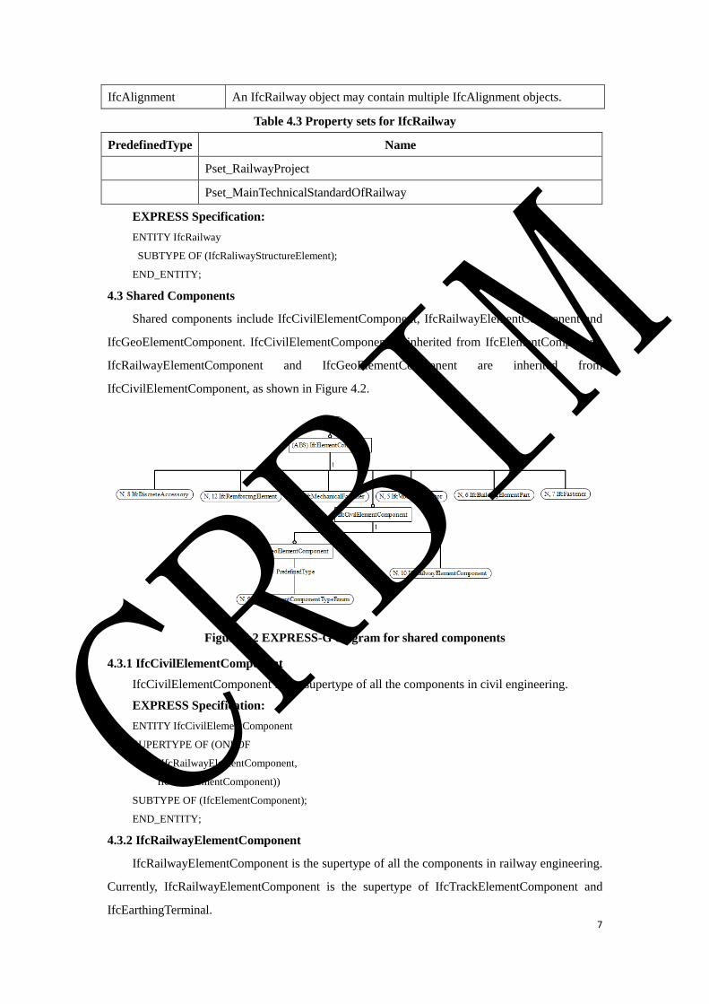
4.3 Shared Components
Shared components include IfcCivilElementComponent, IfcRailwayElementComponent and
IfcGeoElementComponent. IfcCivilElementComponent is inherited from IfcElementComponent.
IfcRailwayElementComponent and IfcGeoElementComponent are inherited from
IfcCivilElementComponent, as shown in Figure 4.2.
Figure 4.2 EXPRESS-G diagram for shared components
4.3.1 IfcCivilElementComponent
IfcCivilElementComponent is the supertype of all the components in civil engineering.
EXPRESS Specification:
ENTITY IfcCivilElementComponent
SUPERTYPE OF (ONEOF
(IfcRailwayElementComponent,
IfcGeoElementComponent))
SUBTYPE OF (IfcElementComponent);
END_ENTITY;
4.3.2 IfcRailwayElementComponent
IfcRailwayElementComponent is the supertype of all the components in railway engineering.
Currently, IfcRailwayElementComponent is the supertype of IfcTrackElementComponent and
IfcEarthingTerminal.
CRBIM
8
EXPRESS Specification:
ENTITY IfcRailwayElementComponent
SUPERTYPE OF (ONEOF
(IfcTrackElementComponent,
IfcEarthingTerminal))
SUBTYPE OF (IfcCivilElementComponent);
END_ENTITY;
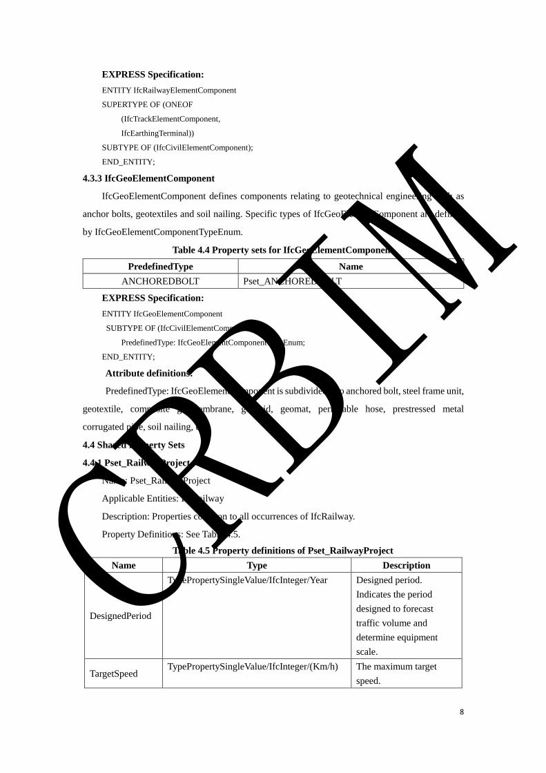
4.3.3 IfcGeoElementComponent
IfcGeoElementComponent defines components relating to geotechnical engineering such as
anchor bolts, geotextiles and soil nailing. Specific types of IfcGeoElementComponent are defined
by IfcGeoElementComponentTypeEnum.
Table 4.4 Property sets for IfcGeoElementComponent
PredefinedType Name
ANCHOREDBOLT Pset_ANCHOREDBOLT
EXPRESS Specification:
ENTITY IfcGeoElementComponent
SUBTYPE OF (IfcCivilElementComponent);
PredefinedType: IfcGeoElementComponentTypeEnum;
END_ENTITY;
Attribute definitions:
PredefinedType: IfcGeoElementComponent is subdivided into anchored bolt, steel frame unit,
geotextile, composite geomembrane, geogrid, geomat, permeable hose, prestressed metal
corrugated pipe, soil nailing, etc.
4.4 Shared Property Sets
4.4.1 Pset_RailwayProject
Name: Pset_RailwayProject
Applicable Entities: IfcRailway
Description: Properties common to all occurrences of IfcRailway.
Property Definitions: See Table 4.5.
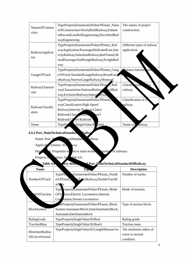
Table 4.5 Property definitions of Pset_RailwayProject
Name Type Description
DesignedPeriod
TypePropertySingleValue/IfcInteger/Year Designed period.
Indicates the period
designed to forecast
traffic volume and
determine equipment
scale.
TargetSpeed TypePropertySingleValue/IfcInteger/(Km/h) The maximum target
speed.
CRBIM
9
NatureOfConstru
ction
TypePropertyEnumeratedValue/PEnum_Natur
eOfConstruction:NewlyBuiltRailway,Enhanc
edSecondLineRailEngineering,ElectrifiedRail
wayEngineering
The nature of project
construction.
RailwayApplicat
ion
TypePropertyEnumeratedValue/PEnum_Rail
wayApplication:PassengerDedicatedLine,Inte
rcityRailway,SuburbanRailway,RailTransit,M
ixedPassengerAndFreightRailway,FreightRail
way
Different types of railway
application.
GaugeOfTrack
TypePropertyEnumeratedValue/PEnum_Gaug
eOfTrack:StandardGaugeRailway,BroadGaug
eRailway,NarrowGaugeRailway,Monorail
Distance between two
rails.
RailwayCharacte
rion
TypePropertyEnumeratedValue/PEnum_Rail
wayCharacterion:NationalRailway,LocalRail
way,ExclusiveRailway,IndustrialSiding
Characterization of a
railway.
RailwayClassific
ation
TypePropertyEnumeratedValue/PEnum_Rail
wayClassification:High-Speed
Railway,Intercity Railway,Class1
Railroad,Class2 Railroad,Class3
Railroad,Class4 Railroad
Classification of a
railway.
Name TypePropertySingleValue/IfcLabel Name of a railway.
4.4.2 Pset_MainTechnicalStandardOfRailway
Name: Pset_MainTechnicalStandardOfRailway
Applicable Entities: IfcRailway
Description: Properties related to main technical standard of railways.
Property Definitions: See Table 4.6.
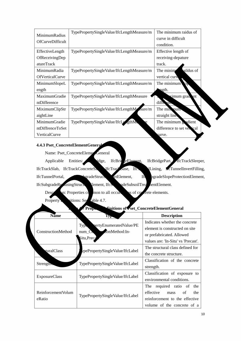
Table 4.6 Property definitions of Pset_MainTechnicalStandardOfRailway
Name Type Description
NumberOfTrack
TypePropertyEnumeratedValue/PEnum_Numb
erOfTrack:SingleTrackRailway,DoubleTrackR
ailway
Number of tracks.
ModeOfTraction
TypePropertyEnumeratedValue/PEnum_Mode
OfTraction:Electric Locomotive,Internal
Combustion,Stream Locomotive
Mode of traction.
BlockSystem
TypePropertyEnumeratedValue/PEnum_Block
System:AutomaticBlock,SemiAutomaticBlock,
AutomaticInterStationblock
Type of section block.
RulingGrade TypePropertySingleValue/IfcReal Ruling grade.
TractionMass TypePropertySingleValue/IfcReal/t Traction mass.
MinimumRadius
OfCurveNormal
TypePropertySingleValue/IfcLengthMeasure/m The minimum radius of
curve in normal
condition.
CRBIM
10
MinimumRadius
OfCurveDifficult
TypePropertySingleValue/IfcLengthMeasure/m The minimum raidus of
curve in difficult
condition.
EffectiveLength
OfReceivingDep
atureTrack
TypePropertySingleValue/IfcLengthMeasure/m Effective length of
receiving-depature
track.
MinimumRadia
OfVerticalCurve
TypePropertySingleValue/IfcLengthMeasure/m The minimum raildus of
vertical curve.
MinimumSlopeL
ength
TypePropertySingleValue/IfcLengthMeasure/m The minimum slope
length.
MaximumGradie
ntDifference
TypePropertySingleValue/IfcLengthMeasure The maximum gradient
difference.
MiximumClipStr
aightLine
TypePropertySingleValue/IfcLengthMeasure/m The minimum clip
straight line.
MinimumGradie
ntDiffrenceToSet
VerticalCurve
TypePropertySingleValue/IfcLengthMeasure The minimum gradient
difference to set vertical
curve.
4.4.3 Pset_ConcreteElementGeneral
Name: Pset_ConcreteElementGeneral
Applicable Entities: IfcBridge, IfcBridgeElement, IfcBridgePart, IfcTrackSleeper,
IfcTrackSlab, IfcTrackConcreteSlab, IfcTrackBase, IfcTunnelLining, IfcTunnelInvertFilling,
IfcTunnelPortal, IfcSubgradeStructurePartElement, IfcSubgradeSlopeProtectionElement,
IfcSubgradeRetainingStructureElement, IfcSubgradeSubsoilTreatmentElement.
Description: Properties common to all occurrences of concrete elements.
Property Definitions: See Table 4.7.
Table 4.7 Property definitions of Pset_ConcreteElementGeneral
Name Type Description
ConstructionMethod
TypePropertyEnumeratedValue/PE
num_ConstructionMethod:In-
Situ,Precast
Indicates whether the concrete
element is constructed on site
or prefabricated. Allowed
values are: 'In-Situ' vs 'Precast'.
StructuralClass TypePropertySingleValue/IfcLabel The structural class defined for
the concrete structure.
StrengthClass TypePropertySingleValue/IfcLabel Classification of the concrete
strength.
ExposureClass TypePropertySingleValue/IfcLabel Classification of exposure to
environmental conditions.
ReinforcementVolum
eRatio TypePropertySingleValue/IfcLabel
The required ratio of the
effective mass of the
reinforcement to the effective
volume of the concrete of a
CRBIM

11
reinforced concrete structural
element.
ReinforcementAreaR
atio TypePropertySingleValue/IfcLabel
The required ratio of the
effective area of the
reinforcement to the effective
area of the concrete At any
section of a reinforced concrete
structural element.
DimensionalAccurac
yClass TypePropertySingleValue/IfcLabel
Classification designation of
the dimensional accuracy
requirement according to local
standards.
ConstructionToleranc
eClass TypePropertySingleValue/IfcLabel
Classification designation of
the on-site construction
tolerances according to local
standards.
ConcreteCover TypePropertySingleValue/IfcLengt
hMeasure/m
The protective concrete cover at
the reinforcing bars according
to local building regulations.
ConcreteCoverAtMai
nBars
TypePropertySingleValue/IfcLengt
hMeasure/m
The protective concrete cover at
the main reinforcing bars
according to local building
regulations.
ConcreteCoverAtLin
ks
TypePropertySingleValue/IfcLengt
hMeasure/m
The protective concrete cover at
the reinforcement links
according to local building
regulations.
ReinforcementStrengt
hClass TypePropertySingleValue/IfcLabel
Classification of the
reinforcement strength.
ConcreteAge TypePropertySingleValue/IfcTime/
d
Age of the concrete.
CrackWidth TypePropertySingleValue/IfcLengt
hMeasure/m
Width of the crack.
NetConcreteCover TypePropertySingleValue/IfcLengt
hMeasure/m
Net concrete cover.
degree of prestressing TypePropertySingleValue/IfcLabel Degree of prestressing.
effective prestress TypePropertySingleValue/IfcPressu
reMeasure/Pa
Effective prestress.
4.4.4 Pset_PrecastConcreteElementFabrication
Name: Pset_PrecastConcreteElementFabrication
Applicable Entities: IfcBridgePart, IfcTrackSleeper, IfcTrackSlab
Description: Properties related to precast concrete fabrication.
CRBIM
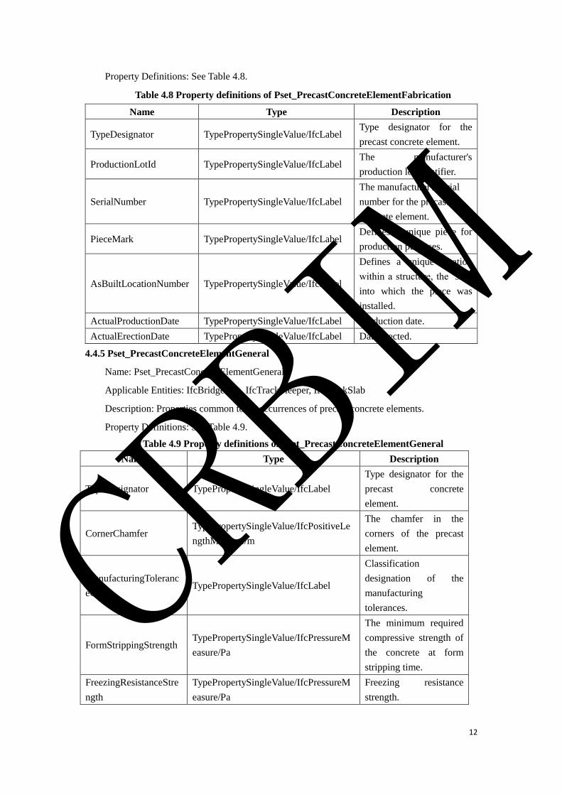
12
Property Definitions: See Table 4.8.
Table 4.8 Property definitions of Pset_PrecastConcreteElementFabrication
Name Type Description
TypeDesignator TypePropertySingleValue/IfcLabel Type designator for the
precast concrete element.
ProductionLotId TypePropertySingleValue/IfcLabel The manufacturer's
production lot identifier.
SerialNumber TypePropertySingleValue/IfcLabel
The manufacturer's serial
number for the precast
concrete element.
PieceMark TypePropertySingleValue/IfcLabel Defines a unique piece for
production purposes.
AsBuiltLocationNumber TypePropertySingleValue/IfcLabel
Defines a unique location
within a structure, the ‘slot’
into which the piece was
installed.
ActualProductionDate TypePropertySingleValue/IfcLabel Production date.
ActualErectionDate TypePropertySingleValue/IfcLabel Date erected.
4.4.5 Pset_PrecastConcreteElementGeneral
Name: Pset_PrecastConcreteElementGeneral
Applicable Entities: IfcBridgePart, IfcTrackSleeper, IfcTrackSlab
Description: Properties common to all occurrences of precast concrete elements.
Property Definitions: See Table 4.9.
Table 4.9 Property definitions of Pset_PrecastConcreteElementGeneral
Name Type Description
TypeDesignator TypePropertySingleValue/IfcLabel
Type designator for the
precast concrete
element.
CornerChamfer TypePropertySingleValue/IfcPositiveLe
ngthMeasure/m
The chamfer in the
corners of the precast
element.
ManufacturingToleranc
eClass TypePropertySingleValue/IfcLabel
Classification
designation of the
manufacturing
tolerances.
FormStrippingStrength TypePropertySingleValue/IfcPressureM
easure/Pa
The minimum required
compressive strength of
the concrete at form
stripping time.
FreezingResistanceStre
ngth
TypePropertySingleValue/IfcPressureM
easure/Pa
Freezing resistance
strength.
CRBIM
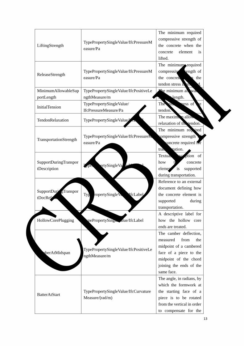
13
LiftingStrength TypePropertySingleValue/IfcPressureM
easure/Pa
The minimum required
compressive strength of
the concrete when the
concrete element is
lifted.
ReleaseStrength TypePropertySingleValue/IfcPressureM
easure/Pa
The minimum required
compressive strength of
the concrete when the
tendon stress is released.
MinimumAllowableSup
portLength
TypePropertySingleValue/IfcPositiveLe
ngthMeasure/m
The minimum allowable
support length.
InitialTension TypePropertySingleValue/
IfcPressureMeasure/Pa
The initial stress of the
tendon.
TendonRelaxation TypePropertySingleValue/IfcLabel The maximum allowable
relaxation of the tendon.
TransportationStrength TypePropertySingleValue/IfcPressureM
easure/Pa
The minimum required
compressive strength of
the concrete required for
transportation.
SupportDuringTranspor
tDescription TypePropertySingleValue/IfcLabel
Textual description of
how the concrete
element is supported
during transportation.
SupportDuringTranspor
tDocReference TypePropertySingleValue/IfcLabel
Reference to an external
document defining how
the concrete element is
supported during
transportation.
HollowCorePlugging TypePropertySingleValue/IfcLabel
A descriptive label for
how the hollow core
ends are treated.
CamberAtMidspan TypePropertySingleValue/IfcPositiveLe
ngthMeasure/m
The camber deflection,
measured from the
midpoint of a cambered
face of a piece to the
midpoint of the chord
joining the ends of the
same face.
BatterAtStart TypePropertySingleValue/IfcCurvature
Measure/(rad/m)
The angle, in radians, by
which the formwork at
the starting face of a
piece is to be rotated
from the vertical in order
to compensate for the
CRBIM
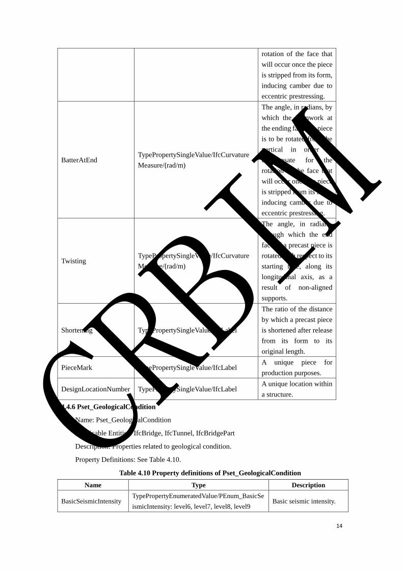
14
rotation of the face that
will occur once the piece
is stripped from its form,
inducing camber due to
eccentric prestressing.
BatterAtEnd TypePropertySingleValue/IfcCurvature
Measure/(rad/m)
The angle, in radians, by
which the formwork at
the ending face of a piece
is to be rotated from the
vertical in order to
compensate for the
rotation of the face that
will occur once the piece
is stripped from its form,
inducing camber due to
eccentric prestressing.
Twisting TypePropertySingleValue/IfcCurvature
Measure/(rad/m)
The angle, in radians,
through which the end
face of a precast piece is
rotated with respect to its
starting face, along its
longitudinal axis, as a
result of non-aligned
supports.
Shortening TypePropertySingleValue/IfcLabel
The ratio of the distance
by which a precast piece
is shortened after release
from its form to its
original length.
PieceMark TypePropertySingleValue/IfcLabel A unique piece for
production purposes.
DesignLocationNumber TypePropertySingleValue/IfcLabel A unique location within
a structure.
4.4.6 Pset_GeologicalCondition
Name: Pset_GeologicalCondition
Applicable Entities: IfcBridge, IfcTunnel, IfcBridgePart
Description: Properties related to geological condition.
Property Definitions: See Table 4.10.
Table 4.10 Property definitions of Pset_GeologicalCondition
Name Type Description
BasicSeismicIntensity TypePropertyEnumeratedValue/PEnum_BasicSe
ismicIntensity: level6, level7, level8, level9 Basic seismic intensity.
CRBIM

15
SeismicPeakGroundAc
celeration
TypePropertySingleValue/IfcAccelerationMeasu
re/(m/s2)
Seismic peak ground
acceleration.
SeismicGroundMotion
ParameterZonation
TypePropertyEnumeratedValue/PEnum_Seismic
GroundMotionParameterZonation:Region1,
Region2, Region3
Seismic ground motion
parameter zonation.
CharacteristicPeriodOf
TheSeismicResponseS
pectrum
TypePropertyEnumeratedValue/PEnum_Charact
eristicPeriodOfTheSeismicResponseSpectrum:
0.25, 0.3, 0.35, 0.4, 0.45, 0.55, 0.65, 0.75, 0.9
Characteristic period of
the seismic response
spectrum.
SiteCategory TypePropertyEnumeratedValue/PEnum_SiteCat
egory:Ⅰ,Ⅱ, Ⅲ, Ⅳ Site category.
Classification of
Surrounding Rock
TypePropertyEnumeratedValue/PEnum_classfic
ation of surrounding rock: Ⅱ, Ⅲ,Ⅳ,Ⅴ, Ⅵ
Classification of
surrounding rock.
Groundwater
Corrosion TypePropertySingleValue/IfcLabel Groundwater corrosion.
Coldest Month of The
Average Temperature
TypePropertySingleValue/IfcThermodynamicTe
mperatureMeasure/ºC
The coldest month of the
average temperature.
Frozen Depth of Soil TypePropertySingleValue/IfcLengthMeasure/m The frozen depth of soil.
4.4.7 Pset_StandardDrawingNumber
Name: Pset_StandardDrawingNumber
Applicable Entities: IfcBridge, IfcBridgePart, IfcBridgeBearing, IfcExpansionInstallation,
IfcPipe
Description: The number of standard drawing.
Property Definitions: See Table 4.11.
Table 4.11 Property definitions of Pset_StandardDrawingNumber
Name Type Description
StandardDrawingNumberT
ype
TypePropertyEnumeratedValue/IfcLabel/PEnu
m_StandardDrawingNumberType:MinisterialL
evelStandardDrawing,EnterpriseLevelStandard
Drawing,ProjectLevelStandardDrawing,Others
Type of the
standard drawing.
StandardDrawingNumber TypePropertySingleValue/IfcLabel Number of the
standard drawing.
4.4.8 Pset_RailwayElementCommon
Name: Pset_RailwayElementCommon
Applicable Entities: IfcCivilElement, IfcCivilStructureElement, IfcPipeSegment
Description: Common properties of all occurrences of railway.
Property Definitions: See Table 4.12.
Table 4.12 Property definitions of Pset_RailwayElementCommon
Name Type Description
Reference TypePropertySingleValue/IfcIdentifier Reference.
Status TypePropertyEnumeratedValue/IfcLabel/PEnum
_RailwayElementStatus:NEW,EXISTING,DEM
The status of railway
elements.
CRBIM
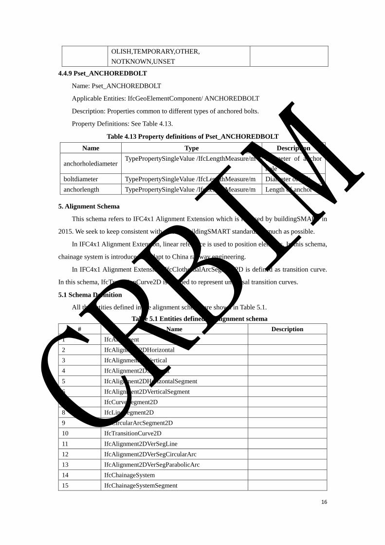
16
OLISH,TEMPORARY,OTHER,
NOTKNOWN,UNSET
4.4.9 Pset_ANCHOREDBOLT
Name: Pset_ANCHOREDBOLT
Applicable Entities: IfcGeoElementComponent/ ANCHOREDBOLT
Description: Properties common to different types of anchored bolts.
Property Definitions: See Table 4.13.
Table 4.13 Property definitions of Pset_ANCHOREDBOLT
Name Type Description
anchorholediameter TypePropertySingleValue /IfcLengthMeasure/m Diameter of anchor
hole
boltdiameter TypePropertySingleValue /IfcLengthMeasure/m Diameter of bolt
anchorlength TypePropertySingleValue /IfcLengthMeasure/m Length of anchor
5. Alignment Schema
This schema refers to IFC4x1 Alignment Extension which is released by buildingSMART in
2015. We seek to keep consistent with existed buildingSMART standards as much as possible.
In IFC4x1 Alignment Extension, linear reference is used to position elements. In this schema,
chainage system is introduced to adapt to China railway engineering.
In IFC4x1 Alignment Extension, IfcClothoidalArcSegment2D is defined as transition curve.
In this schema, IfcTransitionCurve2D is defined to represent universal transition curves.
5.1 Schema Definition
All the entities defined in the alignment schema are shown in Table 5.1.
Table 5.1 Entities defined in Alignment schema
# Name Description
1 IfcAlignment
2 IfcAlignment2DHorizontal
3 IfcAlignment2DVertical
4 IfcAlignment2DSegment
5 IfcAlignment2DHorizontalSegment
6 IfcAlignment2DVerticalSegment
7 IfcCurveSegment2D
8 IfcLineSegment2D
9 IfcCircularArcSegment2D
10 IfcTransitionCurve2D
11 IfcAlignment2DVerSegLine
12 IfcAlignment2DVerSegCircularArc
13 IfcAlignment2DVerSegParabolicArc
14 IfcChainageSystem
15 IfcChainageSystemSegment
CRBIM

17
IfcAlignment is used to define a reference system to position elements mainly for linear
construction works, such as roads, rails, etc. IfcAlignment is composed of
IfcAlignment2DHorizontal, IfcAlignment2DVertical and IfcChainageSystem. The alignment in 3D
space is combined by IfcAlignment2DHorizontal and IfcAlignment2DVertical.
An IfcAlignment2DHorizontal is a linear reference projected onto the horizontal x/y plane,
which is composed of a group of consecutively connected IfcAlignment2DHorizontalSegments.
Each IfcAlignment2DHorizontalSegment has an IfcCurveSegment2D. IfcCurveSegment2D can be
divided into IfcLineSegment2D, IfcCircularArcSegment2D and IfcTransitionCurve2D. The
adjacent IfcAlignment2DHorizontalSegments may have tangential continuity or point continuity.
An IfcAlignment2DVertical is an elevation profile along the horizontal alignment, which is
composed of a group of consecutively connected IfcAlignment2DVerticalSegments.
IfcAlignment2DVertical can be divided into IfcAlignment2DVerSegLine,
IfcAlignment2DVerSegCircularArc and IfcAlignment2DVerSegParabolicArc. The adjacent
IfcAlignment2DVerticalSegments may have tangential continuity or point continuity.
IfcChainageSystem is defined by a group of consecutively connected
IfcChainageSystemSegments.
Figure 5.1 shows the relationships of all the classes in this alignment schema.
CRBIM
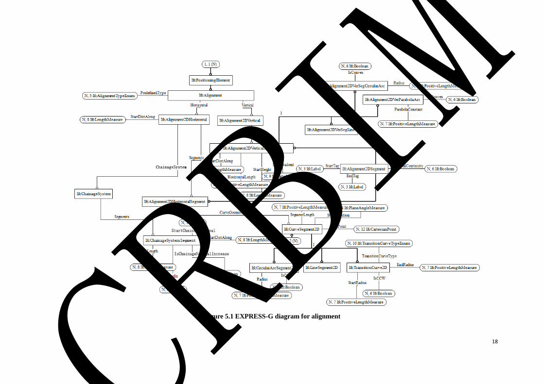
18
Figure 5.1 EXPRESS-G diagram for alignment
CRBIM

19
5.2 Type Definition
5.2.1 IfcAlignmentTypeEnum
IfcAlignmentTypeEnum defines the different types of reference methods to locate by
referencing this alignment.
Enumerated Item Definitions:
ABSOLUTE;
CHAINAGESYSTEM;
USERDEFINED;
NOTDEFINED.
EXPRESS Specification:
TYPE IfcAlignmentTypeEnum =ENUMERATION OF
(ABSOLUTE
,CHAINAGESYSTEM
,USERDEFINED
,NOTDEFINED
);
END_TYPE;
5.2.2 IfcTransitionCurveTypeEnum
IfcTransitionCurveTypeEnum defines the different types of transition curves.
Enumerated Item Definitions:
BLOSSCURVE;
CLOTHOIDCURVE;
SINUSOIDALCURVE;
COSINSOIDALCURVE;
CUBICPARABOLAS;
USERDEFINED;
NOTDEFINED.
EXPRESS Specification:
TYPE IfcTransitionCurveTypeEnum =ENUMERATION OF
(BLOSSCURVE
,CLOTHOIDCURVE
,SINUSOIDALCURVE
,COSINSOIDALCURVE
,CUBICPARABOLAS
,USERDEFINED
,NOTDEFINED
);
CRBIM

20
END_TYPE;
5.3 Entity Definition
5.3.1 IfcAlignment
5.3.1.1 Entity definition
IfcAlignment is used to define a reference system to position elements mainly for linear
construction works, such as roads, rails, etc. IfcAlignment is a subtype of IfcPositioningElement,
which is composed of IfcAlignment2DHorizontal, IfcAlignment2DVertical and IfcChainageSystem.
Usually, the alignment in 3D space is combined by the horizontal and vertical alignment. An
IfcAlignment2DHorizontal is a linear reference projected onto the horizontal x/y plane. An
IfcAlignment2DVertical is an elevation profile along the horizontal alignment. The horizontal
alignment can be shared by several alignments with its own vertical alignments.
Valid representations of IfcAlignment include:
(1) a complete definition including a single horizontal, vertical (represented by their
alignment segments) and a 3D alignment;
(2) a definition including a single horizontal and vertical alignment (represented by their
alignment segments) without a generated 3D alignment;
(3) a definition only including a horizontal alignment (represented by its horizontal
alignment segments) without a vertical and 3D alignment;
(4) a definition only including a horizontal alignment by a simple 2D line representation
without alignment segments (such as in very early planning phases or as a map
representation);
(5) a definition only including a 3D alignment (such as coming from a survey) without
horizontal and vertical alignment segments.
An IfcGroup entity can aggregate corresponding alignments to form an alignment system.
5.3.1.2 Attribute definitions
Table 5.2 Attributes of IfcAlignment
# Attribute Type Cardinality Description
1 PredefinedType IfcAlignmentTypeEnum [0:1] Reference methods, see
definition in 5.2.1.
2 Horizontal IfcAlignment2DHorizontal [0:1] Horizontal alignment.
3 Vertical IfcAlignment2DVertical [0:1] Vertical alignment.
4 LinearRefMethod IfcLabel [0:1] Descriptive names for
the Linear Referencing
Method used to
position items along
the alignment.
5.3.1.3 EXPRESS specification
ENTITY IfcAlignment
CRBIM
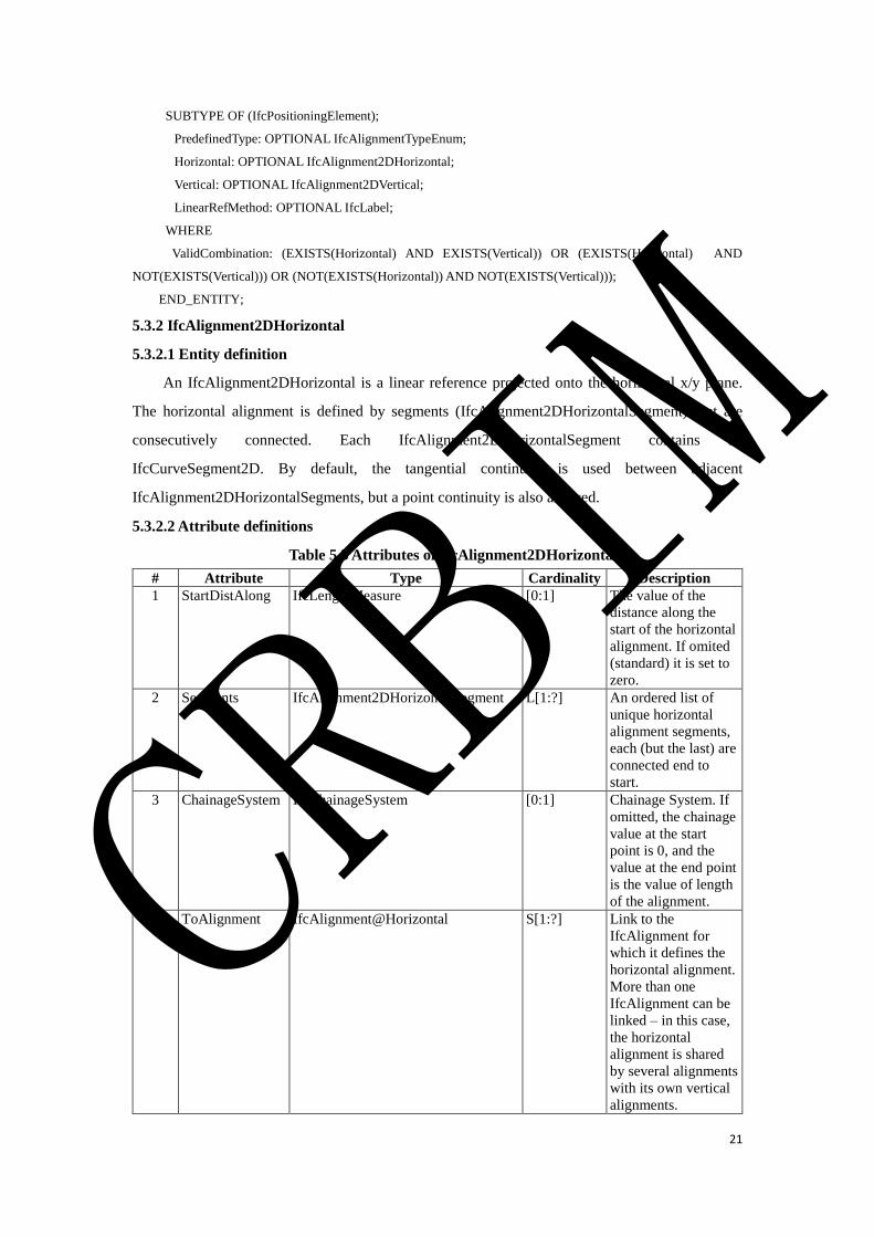
21
SUBTYPE OF (IfcPositioningElement);
PredefinedType: OPTIONAL IfcAlignmentTypeEnum;
Horizontal: OPTIONAL IfcAlignment2DHorizontal;
Vertical: OPTIONAL IfcAlignment2DVertical;
LinearRefMethod: OPTIONAL IfcLabel;
WHERE
ValidCombination: (EXISTS(Horizontal) AND EXISTS(Vertical)) OR (EXISTS(Horizontal) AND
NOT(EXISTS(Vertical))) OR (NOT(EXISTS(Horizontal)) AND NOT(EXISTS(Vertical)));
END_ENTITY;
5.3.2 IfcAlignment2DHorizontal
5.3.2.1 Entity definition
An IfcAlignment2DHorizontal is a linear reference projected onto the horizontal x/y plane.
The horizontal alignment is defined by segments (IfcAlignment2DHorizontalSegment) that are
consecutively connected. Each IfcAlignment2DHorizontalSegment contains an
IfcCurveSegment2D. By default, the tangential continuity is used between adjacent
IfcAlignment2DHorizontalSegments, but a point continuity is also allowed.
5.3.2.2 Attribute definitions
Table 5.3 Attributes of IfcAlignment2DHorizontal
# Attribute Type Cardinality Description
1 StartDistAlong IfcLengthMeasure [0:1] The value of the
distance along the
start of the horizontal
alignment. If omited
(standard) it is set to
zero.
2 Segments IfcAlignment2DHorizontalSegment L[1:?] An ordered list of
unique horizontal
alignment segments,
each (but the last) are
connected end to
start.
3 ChainageSystem IfcChainageSystem [0:1] Chainage System. If
omitted, the chainage
value at the start
point is 0, and the
value at the end point
is the value of length
of the alignment.
4 ToAlignment IfcAlignment@Horizontal S[1:?] Link to the
IfcAlignment for
which it defines the
horizontal alignment.
More than one
IfcAlignment can be
linked – in this case,
the horizontal
alignment is shared
by several alignments
with its own vertical
alignments.
CRBIM
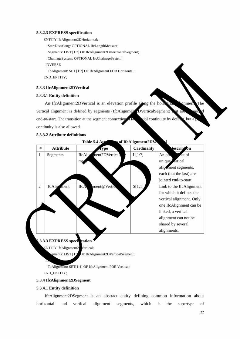
22
5.3.2.3 EXPRESS specification
ENTITY IfcAlignment2DHorizontal;
StartDistAlong: OPTIONAL IfcLengthMeasure;
Segments: LIST [1:?] OF IfcAlignment2DHorizontalSegment;
ChainageSystem: OPTIONAL IfcChainageSystem;
INVERSE
ToAlignment: SET [1:?] OF IfcAlignment FOR Horizontal;
END_ENTITY;
5.3.3 IfcAlignment2DVertical
5.3.3.1 Entity definition
An IfcAlignment2DVertical is an elevation profile along the horizontal alignment. The
vertical alignment is defined by segments (IfcAlignment2DVerticalSegment) that are connected
end-to-start. The transition at the segment connection is tangential continuity by default, but a point
continuity is also allowed.
5.3.3.2 Attribute definitions
Table 5.4 Attributes of IfcAlignment2DVertical
# Attribute Type Cardinality Description
1 Segments IfcAlignment2DVerticalSeg
ment
L[1:?] An ordered list of
unique vertical
alignment segments,
each (but the last) are
jointed end-to-start
2 ToAlignment IfcAlignment@Vertical S[1:1] Link to the IfcAlignment
for which it defines the
vertical alignment. Only
one IfcAlignment can be
linked, a vertical
alignment can not be
shared by several
alignments.
5.3.3.3 EXPRESS specification
ENTITY IfcAlignment2DVertical;
Segments: LIST [1:?] OF IfcAlignment2DVerticalSegment;
INVERSE
ToAlignment: SET[1:1] OF IfcAlignment FOR Vertical;
END_ENTITY;
5.3.4 IfcAlignment2DSegment
5.3.4.1 Entity definition
IfcAlignment2DSegment is an abstract entity defining common information about
horizontal and vertical alignment segments, which is the supertype of
CRBIM
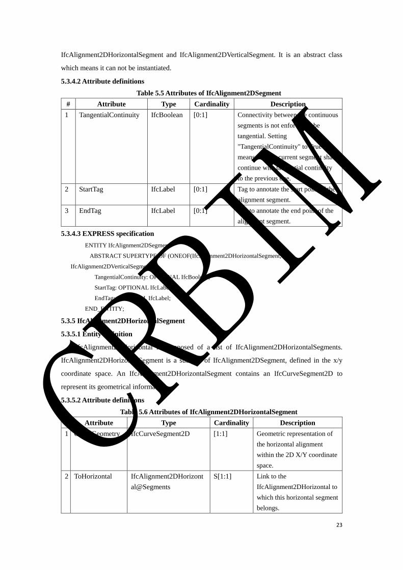
23
IfcAlignment2DHorizontalSegment and IfcAlignment2DVerticalSegment. It is an abstract class
which means it can not be instantiated.
5.3.4.2 Attribute definitions
Table 5.5 Attributes of IfcAlignment2DSegment
# Attribute Type Cardinality Description
1 TangentialContinuity IfcBoolean [0:1] Connectivity between the continuous
segments is not enforced to be
tangential. Setting
"TangentialContinuity" to True
means that the current segment shall
continue with tangential continuity
to the previous one.
2 StartTag IfcLabel [0:1] Tag to annotate the start point of the
alignment segment.
3 EndTag IfcLabel [0:1] Tag to annotate the end point of the
alignment segment.
5.3.4.3 EXPRESS specification
ENTITY IfcAlignment2DSegment
ABSTRACT SUPERTYPE OF (ONEOF(IfcAlignment2DHorizontalSegment,
IfcAlignment2DVerticalSegment));
TangentialContinuity: OPTIONAL IfcBoolean;
StartTag: OPTIONAL IfcLabel;
EndTag: OPTIONAL IfcLabel;
END_ENTITY;
5.3.5 IfcAlignment2DHorizontalSegment
5.3.5.1 Entity definition
IfcAlignment2DHorizontal is composed of a list of IfcAlignment2DHorizontalSegments.
IfcAlignment2DHorizontalSegment is a subtype of IfcAlignment2DSegment, defined in the x/y
coordinate space. An IfcAlignment2DHorizontalSegment contains an IfcCurveSegment2D to
represent its geometrical information.
5.3.5.2 Attribute definitions
Table 5.6 Attributes of IfcAlignment2DHorizontalSegment
# Attribute Type Cardinality Description
1 CurveGeometry IfcCurveSegment2D [1:1] Geometric representation of
the horizontal alignment
within the 2D X/Y coordinate
space.
2 ToHorizontal IfcAlignment2DHorizont
al@Segments
S[1:1] Link to the
IfcAlignment2DHorizontal to
which this horizontal segment
belongs.
CRBIM
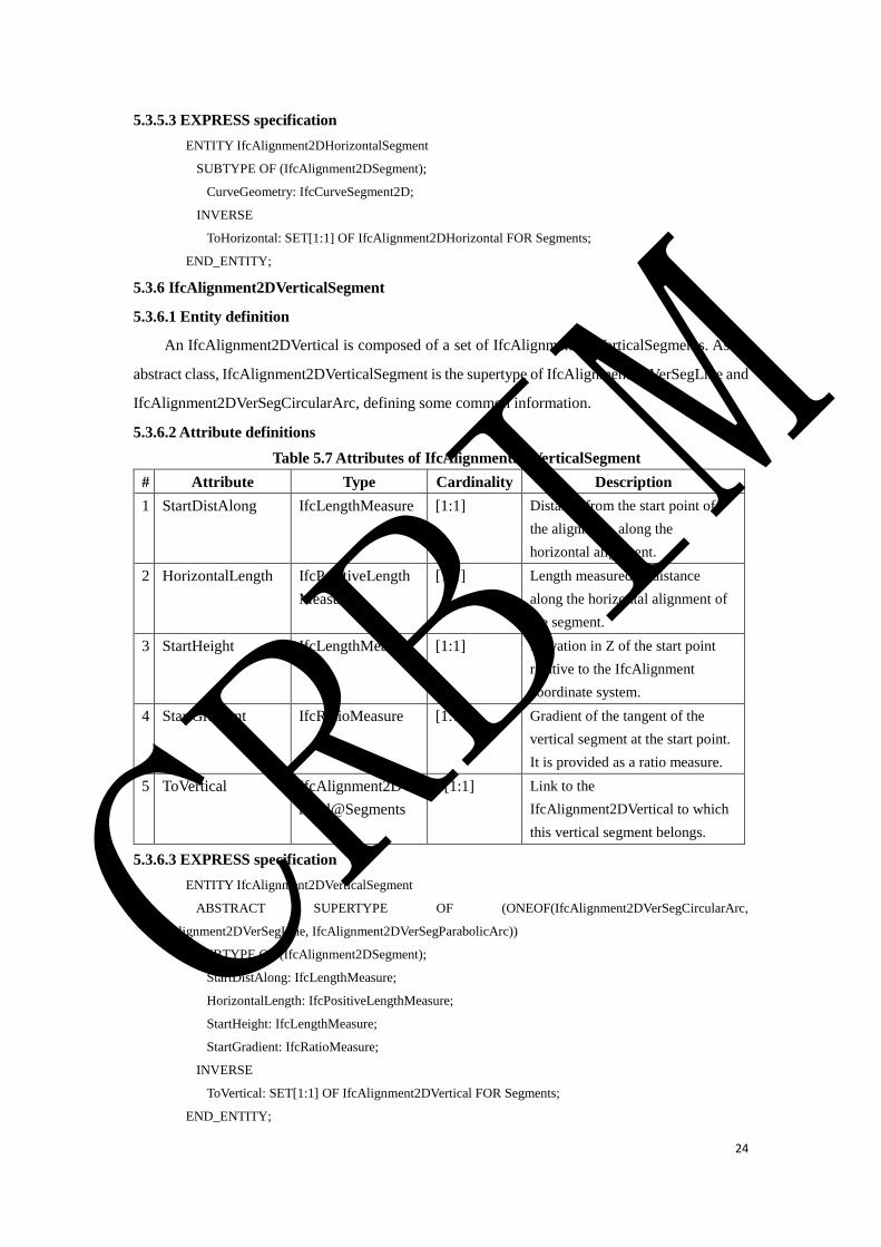
24
5.3.5.3 EXPRESS specification
ENTITY IfcAlignment2DHorizontalSegment
SUBTYPE OF (IfcAlignment2DSegment);
CurveGeometry: IfcCurveSegment2D;
INVERSE
ToHorizontal: SET[1:1] OF IfcAlignment2DHorizontal FOR Segments;
END_ENTITY;
5.3.6 IfcAlignment2DVerticalSegment
5.3.6.1 Entity definition
An IfcAlignment2DVertical is composed of a set of IfcAlignment2DVerticalSegments. As an
abstract class, IfcAlignment2DVerticalSegment is the supertype of IfcAlignment2DVerSegLine and
IfcAlignment2DVerSegCircularArc, defining some common information.
5.3.6.2 Attribute definitions
Table 5.7 Attributes of IfcAlignment2DVerticalSegment
# Attribute Type Cardinality Description
1 StartDistAlong IfcLengthMeasure [1:1] Distance from the start point of
the alignment, along the
horizontal alignment.
2 HorizontalLength IfcPositiveLength
Measure
[1:1] Length measured as distance
along the horizontal alignment of
the segment.
3 StartHeight IfcLengthMeasure [1:1] Elevation in Z of the start point
relative to the IfcAlignment
coordinate system.
4 StartGradient IfcRatioMeasure [1:1] Gradient of the tangent of the
vertical segment at the start point.
It is provided as a ratio measure.
5 ToVertical IfcAlignment2DVe
rtical@Segments
S[1:1] Link to the
IfcAlignment2DVertical to which
this vertical segment belongs.
5.3.6.3 EXPRESS specification
ENTITY IfcAlignment2DVerticalSegment
ABSTRACT SUPERTYPE OF (ONEOF(IfcAlignment2DVerSegCircularArc,
IfcAlignment2DVerSegLine, IfcAlignment2DVerSegParabolicArc))
SUBTYPE OF (IfcAlignment2DSegment);
StartDistAlong: IfcLengthMeasure;
HorizontalLength: IfcPositiveLengthMeasure;
StartHeight: IfcLengthMeasure;
StartGradient: IfcRatioMeasure;
INVERSE
ToVertical: SET[1:1] OF IfcAlignment2DVertical FOR Segments;
END_ENTITY;
CRBIM
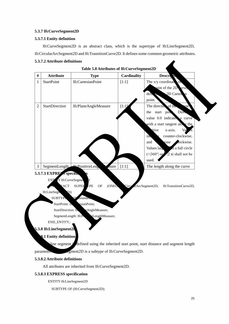
25
5.3.7 IfcCurveSegment2D
5.3.7.1 Entity definition
IfcCurveSegment2D is an abstract class, which is the supertype of IfcLineSegment2D,
IfcCircularArcSegment2D and IfcTransitionCurve2D. It defines some common geometric attributes.
5.3.7.2 Attribute definitions
Table 5.8 Attributes of IfcCurveSegment2D
# Attribute Type Cardinality Description
1 StartPoint IfcCartesianPoint [1:1] The x/y coordinates of the
start point of the 2D curve,
defined by a 2D Cartesian
point.
2 StartDirection IfcPlaneAngleMeasure [1:1] The direction of the tangent at
the start point. Direction
value 0.0 indicates a curve
with a start tangent along the
positive x-axis. Values
increase counter-clockwise,
and decrease clockwise.
Values larger than a full circle
(>|360°| or > |2 π| shall not be
used.
3 SegmentLength IfcPositiveLengthMeasure [1:1] The length along the curve
5.3.7.3 EXPRESS specification
ENTITY IfcCurveSegment2D
ABSTRACT SUPERTYPE OF (ONEOF(IfcCircularArcSegment2D, IfcTransitionCurve2D,
IfcLineSegment2D))
SUBTYPE OF (IfcBoundedCurve);
StartPoint: IfcCartesianPoint;
StartDirection: IfcPlaneAngleMeasure;
SegmentLength: IfcPositiveLengthMeasure;
END_ENTITY;
5.3.8 IfcLineSegment2D
5.3.8.1 Entity definition
The line segment is defined using the inherited start point, start distance and segment length
parameter. IfcLineSegment2D is a subtype of IfcCurveSegment2D.
5.3.8.2 Attribute definitions
All attributes are inherited from IfcCurveSegment2D.
5.3.8.3 EXPRESS specification
ENTITY IfcLineSegment2D
SUBTYPE OF (IfcCurveSegment2D);
CRBIM
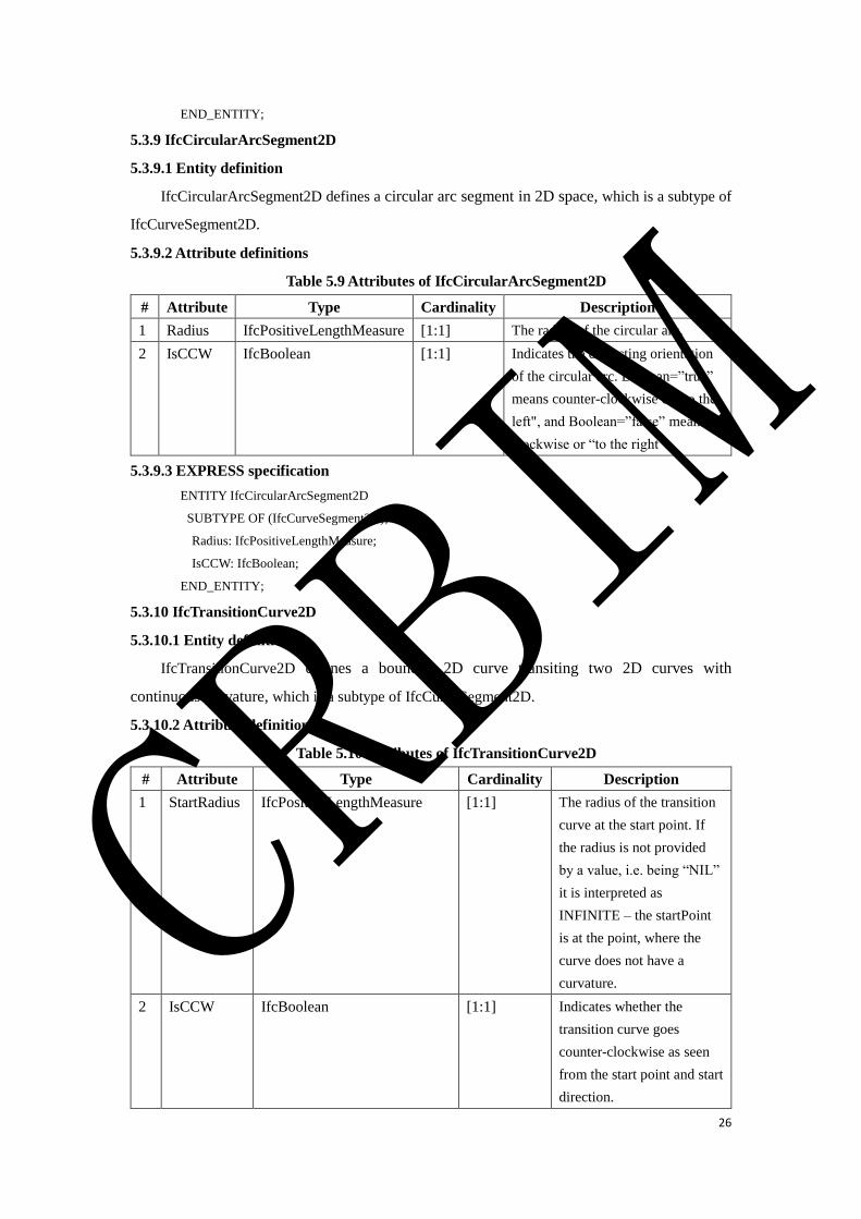
26
END_ENTITY;
5.3.9 IfcCircularArcSegment2D
5.3.9.1 Entity definition
IfcCircularArcSegment2D defines a circular arc segment in 2D space, which is a subtype of
IfcCurveSegment2D.
5.3.9.2 Attribute definitions
Table 5.9 Attributes of IfcCircularArcSegment2D
# Attribute Type Cardinality Description
1 Radius IfcPositiveLengthMeasure [1:1] The radius of the circular arc.
2 IsCCW IfcBoolean [1:1] Indicates the deflecting orientation
of the circular arc. Boolean=”true”
means counter-clockwise or “to the
left", and Boolean=”false” means
clockwise or “to the right”.
5.3.9.3 EXPRESS specification
ENTITY IfcCircularArcSegment2D
SUBTYPE OF (IfcCurveSegment2D);
Radius: IfcPositiveLengthMeasure;
IsCCW: IfcBoolean;
END_ENTITY;
5.3.10 IfcTransitionCurve2D
5.3.10.1 Entity definition
IfcTransitionCurve2D defines a bounded 2D curve transiting two 2D curves with
continuous curvature, which is a subtype of IfcCurveSegment2D.
5.3.10.2 Attribute definitions
Table 5.10 Attributes of IfcTransitionCurve2D
# Attribute Type Cardinality Description
1 StartRadius IfcPositiveLengthMeasure [1:1] The radius of the transition
curve at the start point. If
the radius is not provided
by a value, i.e. being “NIL”
it is interpreted as
INFINITE – the startPoint
is at the point, where the
curve does not have a
curvature.
2 IsCCW IfcBoolean [1:1] Indicates whether the
transition curve goes
counter-clockwise as seen
from the start point and start
direction.
CRBIM
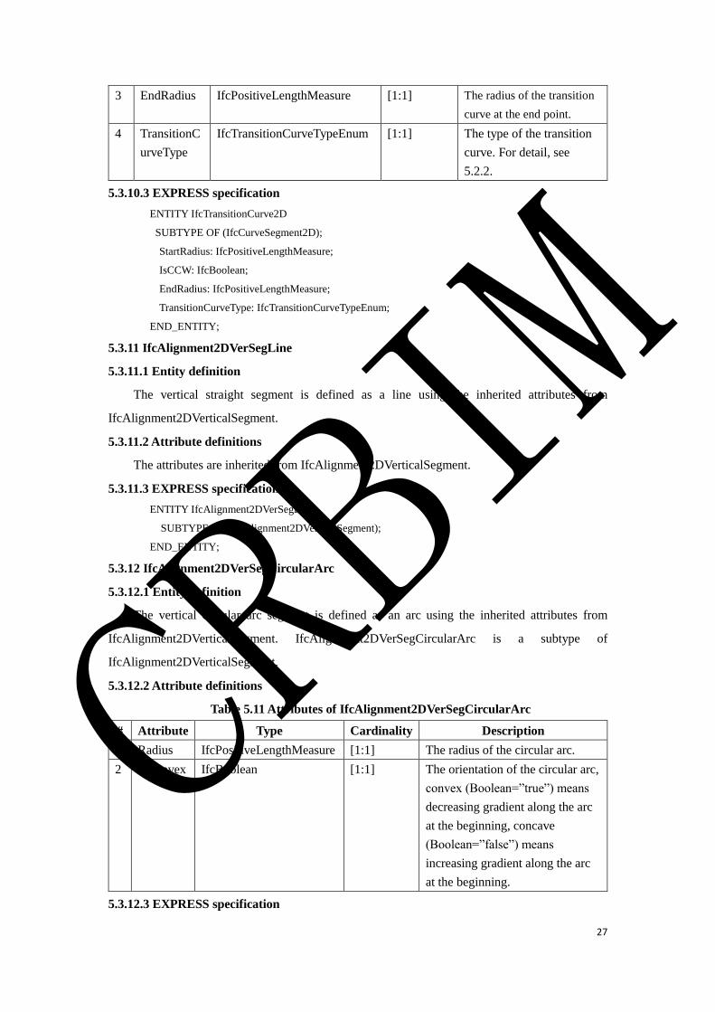
27
3 EndRadius IfcPositiveLengthMeasure [1:1] The radius of the transition
curve at the end point.
4 TransitionC
urveType
IfcTransitionCurveTypeEnum [1:1] The type of the transition
curve. For detail, see
5.2.2.
5.3.10.3 EXPRESS specification
ENTITY IfcTransitionCurve2D
SUBTYPE OF (IfcCurveSegment2D);
StartRadius: IfcPositiveLengthMeasure;
IsCCW: IfcBoolean;
EndRadius: IfcPositiveLengthMeasure;
TransitionCurveType: IfcTransitionCurveTypeEnum;
END_ENTITY;
5.3.11 IfcAlignment2DVerSegLine
5.3.11.1 Entity definition
The vertical straight segment is defined as a line using the inherited attributes from
IfcAlignment2DVerticalSegment.
5.3.11.2 Attribute definitions
The attributes are inherited from IfcAlignment2DVerticalSegment.
5.3.11.3 EXPRESS specification
ENTITY IfcAlignment2DVerSegLine
SUBTYPE OF (IfcAlignment2DVerticalSegment);
END_ENTITY;
5.3.12 IfcAlignment2DVerSegCircularArc
5.3.12.1 Entity definition
The vertical circular arc segment is defined as an arc using the inherited attributes from
IfcAlignment2DVerticalSegment. IfcAlignment2DVerSegCircularArc is a subtype of
IfcAlignment2DVerticalSegment.
5.3.12.2 Attribute definitions
Table 5.11 Attributes of IfcAlignment2DVerSegCircularArc
# Attribute Type Cardinality Description
1 Radius IfcPositiveLengthMeasure [1:1] The radius of the circular arc.
2 IsConvex IfcBoolean [1:1] The orientation of the circular arc,
convex (Boolean=”true”) means
decreasing gradient along the arc
at the beginning, concave
(Boolean=”false”) means
increasing gradient along the arc
at the beginning.
5.3.12.3 EXPRESS specification
CRBIM
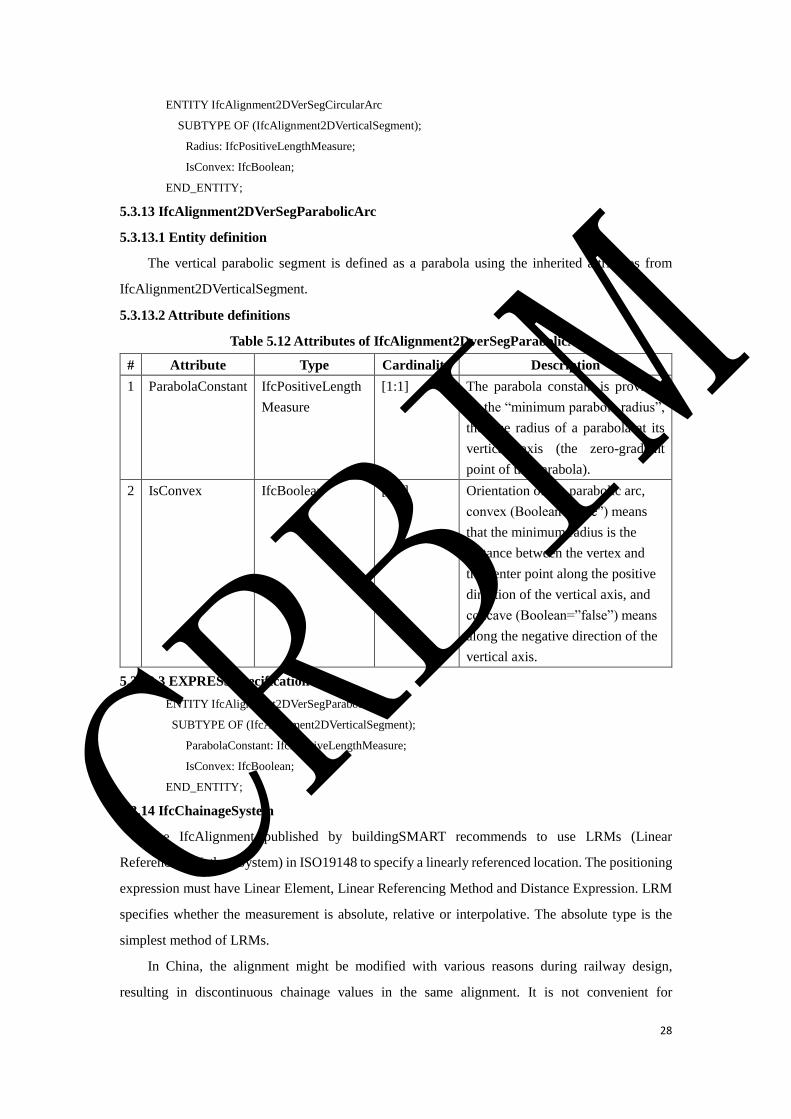
28
ENTITY IfcAlignment2DVerSegCircularArc
SUBTYPE OF (IfcAlignment2DVerticalSegment);
Radius: IfcPositiveLengthMeasure;
IsConvex: IfcBoolean;
END_ENTITY;
5.3.13 IfcAlignment2DVerSegParabolicArc
5.3.13.1 Entity definition
The vertical parabolic segment is defined as a parabola using the inherited attributes from
IfcAlignment2DVerticalSegment.
5.3.13.2 Attribute definitions
Table 5.12 Attributes of IfcAlignment2DverSegParabolicArc
# Attribute Type Cardinality Description
1 ParabolaConstant IfcPositiveLength
Measure
[1:1] The parabola constant is provided
by the “minimum parabola radius”,
the true radius of a parabola at its
vertical axis (the zero-gradient
point of the parabola).
2 IsConvex IfcBoolean [1:1] Orientation of the parabolic arc,
convex (Boolean=”true”) means
that the minimum radius is the
distance between the vertex and
the center point along the positive
direction of the vertical axis, and
concave (Boolean=”false”) means
along the negative direction of the
vertical axis.
5.3.13.3 EXPRESS specification
ENTITY IfcAlignment2DVerSegParabolicArc
SUBTYPE OF (IfcAlignment2DVerticalSegment);
ParabolaConstant: IfcPositiveLengthMeasure;
IsConvex: IfcBoolean;
END_ENTITY;
5.3.14 IfcChainageSystem
The IfcAlignment published by buildingSMART recommends to use LRMs (Linear
Referencing Method System) in ISO19148 to specify a linearly referenced location. The positioning
expression must have Linear Element, Linear Referencing Method and Distance Expression. LRM
specifies whether the measurement is absolute, relative or interpolative. The absolute type is the
simplest method of LRMs.
In China, the alignment might be modified with various reasons during railway design,
resulting in discontinuous chainage values in the same alignment. It is not convenient for
CRBIM
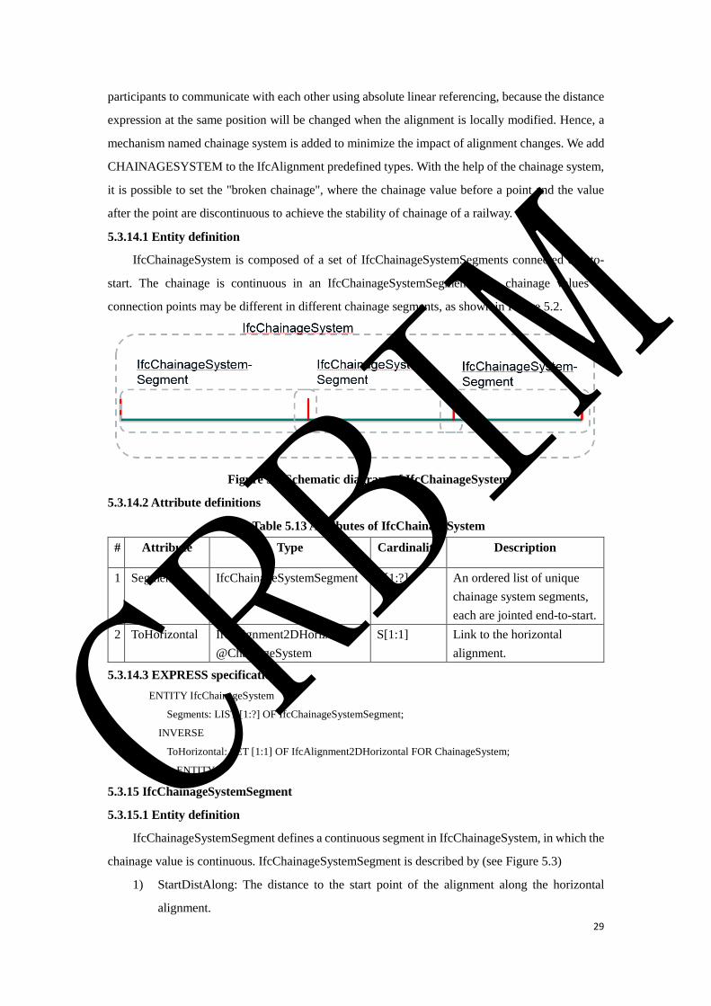
29
participants to communicate with each other using absolute linear referencing, because the distance
expression at the same position will be changed when the alignment is locally modified. Hence, a
mechanism named chainage system is added to minimize the impact of alignment changes. We add
CHAINAGESYSTEM to the IfcAlignment predefined types. With the help of the chainage system,
it is possible to set the "broken chainage", where the chainage value before a point and the value
after the point are discontinuous to achieve the stability of chainage of a railway.
5.3.14.1 Entity definition
IfcChainageSystem is composed of a set of IfcChainageSystemSegments connected end-to-
start. The chainage is continuous in an IfcChainageSystemSegment. The chainage values at
connection points may be different in different chainage segments, as shown in Figure 5.2.
Figure 5.2 Schematic diagram of IfcChainageSystem
5.3.14.2 Attribute definitions
Table 5.13 Attributes of IfcChainageSystem
# Attribute Type Cardinality Description
1 Segments IfcChainageSystemSegment L[1:?] An ordered list of unique
chainage system segments,
each are jointed end-to-start.
2 ToHorizontal IfcAlignment2DHorizontal
@ChainageSystem
S[1:1] Link to the horizontal
alignment.
5.3.14.3 EXPRESS specification
ENTITY IfcChainageSystem
Segments: LIST [1:?] OF IfcChainageSystemSegment;
INVERSE
ToHorizontal: SET [1:1] OF IfcAlignment2DHorizontal FOR ChainageSystem;
END_ENTITY;
5.3.15 IfcChainageSystemSegment
5.3.15.1 Entity definition
IfcChainageSystemSegment defines a continuous segment in IfcChainageSystem, in which the
chainage value is continuous. IfcChainageSystemSegment is described by (see Figure 5.3)
1) StartDistAlong: The distance to the start point of the alignment along the horizontal
alignment.
CRBIM
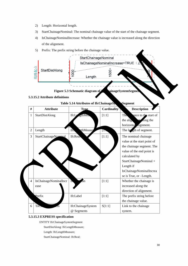
30
2) Length: Horizontal length.
3) StartChainageNominal: The nominal chainage value of the start of the chainage segment.
4) IsChainageNominalIncrease: Whether the chainage value is increased along the direction
of the alignment.
5) Prefix: The prefix string before the chainage value.
Figure 5.3 Schematic diagram of IfcChainageSystemSegment
5.3.15.2 Attribute definitions
Table 5.14 Attributes of IfcChainageSystemSegment
# Attribute Type Cardinality Description
1 StartDistAlong IfcLengthMeasure [1:1] The distance to the start of
the alignment along the
horizontal alignment.
2 Length IfcLengthMeasure [1:1] The length of segment.
3 StartChainageNominal IfcReal [1:1] The nominal chainage
value at the start point of
the chainage segment. The
value of the end point is
calculated by
StartChainageNominal +
Length if
IsChainageNominalIncrea
se is True, or –Length.
4 IsChainageNominalIncr
ease
IfcBoolean [1:1] Whether the chainage is
increased along the
direction of alignment.
5 Prefix IfcLabel [1:1] The prefix string before
the chainage value.
6 ToChinageSystem IfcChainageSystem
@ Segments
S[1:1] Link to the chainage
system.
5.3.15.3 EXPRESS specification
ENTITY IfcChainageSystemSegment
StartDistAlong: IfcLengthMeasure;
Length: IfcLengthMeasure;
StartChainageNominal: IfcReal;
CRBIM
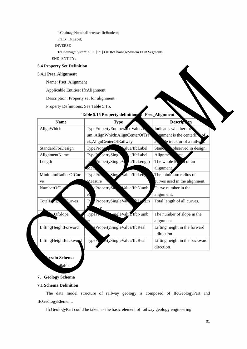
31
IsChainageNominalIncrease: IfcBoolean;
Prefix: IfcLabel;
INVERSE
ToChainageSystem: SET [1:1] OF IfcChainageSystem FOR Segments;
END_ENTITY;
5.4 Property Set Definition
5.4.1 Pset_Alignment
Name: Pset_Alignment
Applicable Entities: IfcAlignment
Description: Property set for alignment.
Property Definitions: See Table 5.15.
Table 5.15 Property definitions of Pset_Alignment
Name Type Description
AlignWhich TypePropertyEnumeratedValue/PEn
um_AlignWhich:AlignCenterOfTra
ck,AlignCenterOfRailway
Indicates whether the
alignment is the centerline of
a single track or of a railway.
StandardForDesign TypePropertySingleValue/IfcLabel Standards observed in design.
AlignmentName TypePropertySingleValue/IfcLabel Alignment name.
Length TypePropertySingleValue/IfcLength
Measure
The whole length of an
alignment.
MinimumRadiusOfCur
ve
TypePropertySingleValue/IfcLength
Measure
The minimum radius of
curves used in the alignment.
NumberOfCurve TypePropertySingleValue/IfcNumb
er
Curve number in the
alignment.
TotalLenghtOfCurves TypePropertySingleValue/IfcLength
Measure
Total length of all curves.
NumberOfSlope TypePropertySingleValue/IfcNumb
er
The number of slope in the
alignment
LiftingHeightForword TypePropertySingleValue/IfcReal Lifting height in the forward
direction.
LiftingHeightBackword TypePropertySingleValue/IfcReal Lifting height in the backward
direction.
6.Terrain Schema
Not available.
7.Geology Schema
7.1 Schema Definition
The data model structure of railway geology is composed of IfcGeologyPart and
IfcGeologyElement.
IfcGeologyPart could be taken as the basic element of railway geology engineering.
CRBIM
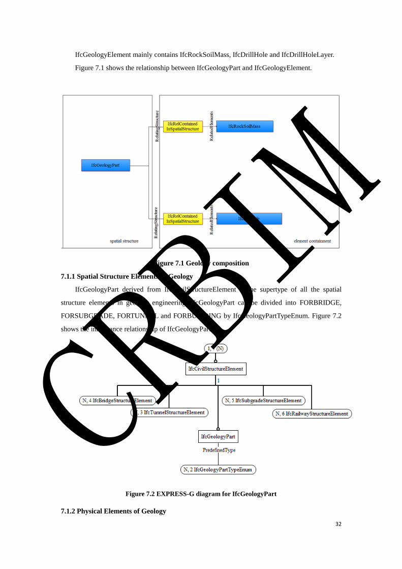
32
IfcGeologyElement mainly contains IfcRockSoilMass, IfcDrillHole and IfcDrillHoleLayer.
Figure 7.1 shows the relationship between IfcGeologyPart and IfcGeologyElement.
Figure 7.1 Geology composition
7.1.1 Spatial Structure Elements of Geology
IfcGeologyPart derived from IfcCivilStructureElement is the supertype of all the spatial
structure elements in geology engineering. IfcGeologyPart can be divided into FORBRIDGE,
FORSUBGRADE, FORTUNNEL and FORBUILDING by IfcGeologyPartTypeEnum. Figure 7.2
shows the inheritance relationship of IfcGeologyPart.
Figure 7.2 EXPRESS-G diagram for IfcGeologyPart
7.1.2 Physical Elements of Geology
CRBIM
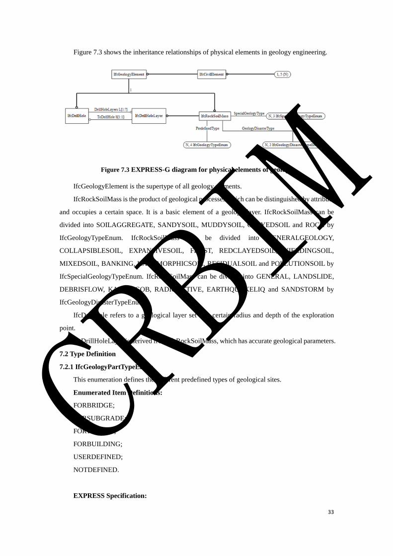
33
Figure 7.3 shows the inheritance relationships of physical elements in geology engineering.
Figure 7.3 EXPRESS-G diagram for physical elements of geology
IfcGeologyElement is the supertype of all geology elements.
IfcRockSoilMass is the product of geological processes which can be distinguished by attribute
and occupies a certain space. It is a basic element of a geology layer. IfcRockSoilMass can be
divided into SOILAGGREGATE, SANDYSOIL, MUDDYSOIL, CLAYEDSOIL and ROCK by
IfcGeologyTypeEnum. IfcRockSoilMass can be divided into GENERALGEOLOGY,
COLLAPSIBLESOIL, EXPANSIVESOIL, FROST, REDCLAYEDSOIL, YIELDINGSOIL,
MIXEDSOIL, BANKING, HALOMORPHICSOIL, RESIDUALSOIL and POLLUTIONSOIL by
IfcSpecialGeologyTypeEnum. IfcRockSoilMass can be divided into GENERAL, LANDSLIDE,
DEBRISFLOW, KARST, GOB, RADIOACTIVE, EARTHQUAKELIQ and SANDSTORM by
IfcGeologyDisasterTypeEnum.
IfcDrillHole refers to a geological layer set in a certain radius and depth of the exploration
point.
IfcDrillHoleLayer is derived from IfcRockSoilMass, which has accurate geological parameters.
7.2 Type Definition
7.2.1 IfcGeologyPartTypeEnum
This enumeration defines the different predefined types of geological sites.
Enumerated Item Definitions:
FORBRIDGE;
FORSUBGRADE;
FORTUNNEL;
FORBUILDING;
USERDEFINED;
NOTDEFINED.
EXPRESS Specification:
CRBIM
34
TYPE IfcGeologyPartTypeEnum= ENUMERATION OF
(FORBRIDGE
, FORSUBGRADE
, FORTUNNEL
, FORBUILDING
, USERDEFINED
, NOTDEFINED
);
END_TYPE;
7.2.2 IfcGeologyTypeEnum
This enumeration defines the different predefined types of geology.
Enumerated Item Definitions:
SOILAGGREGATE;
SANDYSOIL;
MUDDYSOIL;
CLAYEDSOIL;
ROCK;
USERDEFINED;
NOTDEFINED.
EXPRESS Specification:
TYPE IfcGeologyTypeEnum= ENUMERATION OF
(SOILAGGREGATE
, SANDYSOIL
, MUDDYSOIL
, CLAYEDSOIL
, ROCK
, USERDEFINED
, NOTDEFINED
);
END_TYPE;
7.2.3 IfcSpecialGeologyTypeEnum
This enumeration defines the different types of special geology.
Enumerated Item Definitions:
GENERALGEOLOGY;
COLLAPSIBLESOIL;
EXPANSIVESOIL;
FROST;
REDCLAYEDSOIL;
CRBIM

35
YIELDINGSOIL;
MIXEDSOIL;
BANKING;
HALOMORPHICSOIL;
RESIDUALSOIL;
POLLUTIONSOIL;
USERDEFINED;
NOTDEFINED.
EXPRESS Specification:
TYPE IfcSpecialGeologyTypeEnum= ENUMERATION OF
(GENERALGEOLOGY
, COLLAPSIBLESOIL
, EXPANSIVESOIL
, FROST
, REDCLAYEDSOIL
, YIELDINGSOIL
, MIXEDSOIL
, BANKING
, HALOMORPHICSOIL
,RESIDUALSOIL
,POLLUTIONSOIL
,USERDEFINED
, NOTDEFINED
);
END_TYPE;
7.2.4 IfcGeologyDisasterTypeEnum
This enumeration defines the different types of geology disaster.
Enumerated Item Definitions:
GENERAL;
LANDSLIDE;
DEBRISFLOW;
KARST;
GOB;
RADIOACTIVE;
EARTHQUAKELIQ;
SANDSTORM;
USERDEFINED;
NOTDEFINED.
CRBIM
36
EXPRESS Specification:
TYPE IfcGeologyDisasterTypeEnum= ENUMERATION OF
(GENERAL
,LANDSLIDE
,DEBRISFLOW
,KARST
,GOB
,RADIOACTIVE
,EARTHQUAKELIQ
,SANDSTORM
,USERDEFINED
, NOTDEFINED
);
END_TYPE;
7.3 Entity Definition
7.3.1 IfcGeologyPart
IfcGeologyPart is a basic geological engineering unit.
EXPRESS Specification:
ENTITY IfcGeologyPart
SUBTYPE OF (IfcCivilStructureElement);
PredefinedType: IfcGeologyPartTypeEnum;
END_ENTITY;
7.3.2 IfcGeologyElement
IfcGeologyElement is the supertype of all the physical elements in geology engineering.
EXPRESS Specification:
ENTITY IfcGeologyElement
SUPERTYPE OF (ONEOF (IfcRockSoilMass, IfcDrillHole));
SUBTYPE OF (IfcCivilElement);
END_ENTITY;
7.3.3 IfcRockSoilMass
IfcRockSoilMass is defined as a basic element of a geological body. Some rock soil mass
compose the geology of an area.
Table 7.1 Property sets for IfcRockSoilMass
PredefinedType Name
Pset_RockSoilMassCommon
Pset_RockSoilMassProperty
Table 7.2 Property sets for IfcRockSoilMass
SpecialGeologyType Name
CRBIM
37
COLLAPSIBLESOIL Pset_SpecialGeology_COLLAPSIBLESOI
EXPANSIVESOIL Pset_SpecialGeology_EXPANSIVESOIL
FROST Pset_SpecialGeology_FROST
HALOMORPHICSOIL Pset_SpecialGeology_HALOMORPHICSOIL
POLLUTIONSOIL Pset_SpecialGeology_POLLUTIONSOIL
Table 7.3 Property sets for IfcRockSoilMass
GeologyDisasterType Name
LANDSLIDE Pset_GeologyDisaster_LANDSLIDE
DEBRISFLOW Pset_GeologyDisaster_DEBRISFLOW
KARST Pset_GeologyDisaster_KARST
GOB Pset_GeologyDisaster_GOB
RADIOACTIVE Pset_GeologyDisaster_RADIOACTIVE
SANDSTORM Pset_GeologyDisaster_SANDSTORM
EXPRESS Specification:
ENTITY IfcRockSoilMass
SUBTYPE OF (IfcGeologyElement);
PredefinedType: IfcGeologyTypeEnum;
SpecialGeologyType: IfcSpecialGeologyTypeEnum;
GeologyDisasterType: IfcGeologyDisasterTypeEnum;
END_ENTITY;
Attribute definitions:
PreDefinedType: It contains Soilaggregate, Sandysoil, Muddysoil, Clayedsoil and Rock.
SpecialGeologyType: It contains General Geology, Collapsible Soil, Expansive Soil, Frost,
Red Clayed Soil, Yielding Soil, Mixed Soil, Banking, Halomorphic Soil, Residual Soil and Pollution
Soil.
GeologyDisasterType: It contains General, Landslide, Debris Flow, Karst, Gob, Radioactive,
Earthquake Liquid and Sand Storm.
7.3.4 IfcDrillHole
IfcDrillHole is defined as a geological layer set in a certain radius and depth of the exploration
point.
Table 7.4 Property sets for IfcDrillHole
PredefinedType Name
Pset_DrillHole
EXPRESS Specification:
ENTITY IfcDrillHole
SUBTYPE OF (IfcGeologyElement);
DrillHoleLayers: LIST [1:?] OF IfcDrillHoleLayer;
END_ENTITY;
7.3.5 IfcDrillHoleLayer
IfcDrillHoleLayer is a geological layer in a certain radius and depth of the exploration point.
CRBIM
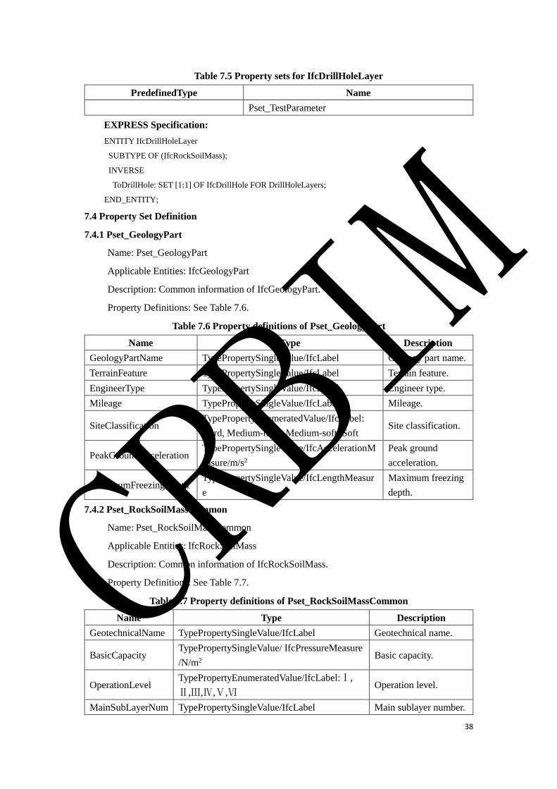
38
Table 7.5 Property sets for IfcDrillHoleLayer
PredefinedType Name
Pset_TestParameter
EXPRESS Specification:
ENTITY IfcDrillHoleLayer
SUBTYPE OF (IfcRockSoilMass);
INVERSE
ToDrillHole: SET [1:1] OF IfcDrillHole FOR DrillHoleLayers;
END_ENTITY;
7.4 Property Set Definition
7.4.1 Pset_GeologyPart
Name: Pset_GeologyPart
Applicable Entities: IfcGeologyPart
Description: Common information of IfcGeologyPart.
Property Definitions: See Table 7.6.
Table 7.6 Property definitions of Pset_GeologyPart
Name Type Description
GeologyPartName TypePropertySingleValue/IfcLabel Geology part name.
TerrainFeature TypePropertySingleValue/IfcLabel Terrain feature.
EngineerType TypePropertySingleValue/IfcLabel Engineer type.
Mileage TypePropertySingleValue/IfcLabel Mileage.
SiteClassification TypePropertyEnumeratedValue/IfcLabel:
Hard, Medium-hard, Medium-soft, Soft Site classification.
PeakGroundAcceleration TypePropertySingleValue/IfcAccelerationM
easure/m/s2
Peak ground
acceleration.
MaximumFreezingDepth TypePropertySingleValue/IfcLengthMeasur
e
Maximum freezing
depth.
7.4.2 Pset_RockSoilMassCommon
Name: Pset_RockSoilMassCommon
Applicable Entities: IfcRockSoilMass
Description: Common information of IfcRockSoilMass.
Property Definitions: See Table 7.7.
Table 7.7 Property definitions of Pset_RockSoilMassCommon
Name Type Description
GeotechnicalName TypePropertySingleValue/IfcLabel Geotechnical name.
BasicCapacity TypePropertySingleValue/ IfcPressureMeasure
/N/m2 Basic capacity.
OperationLevel TypePropertyEnumeratedValue/IfcLabel:Ⅰ,
Ⅱ,Ⅲ,Ⅳ,Ⅴ,Ⅵ Operation level.
MainSubLayerNum TypePropertySingleValue/IfcLabel Main sublayer number.
CRBIM
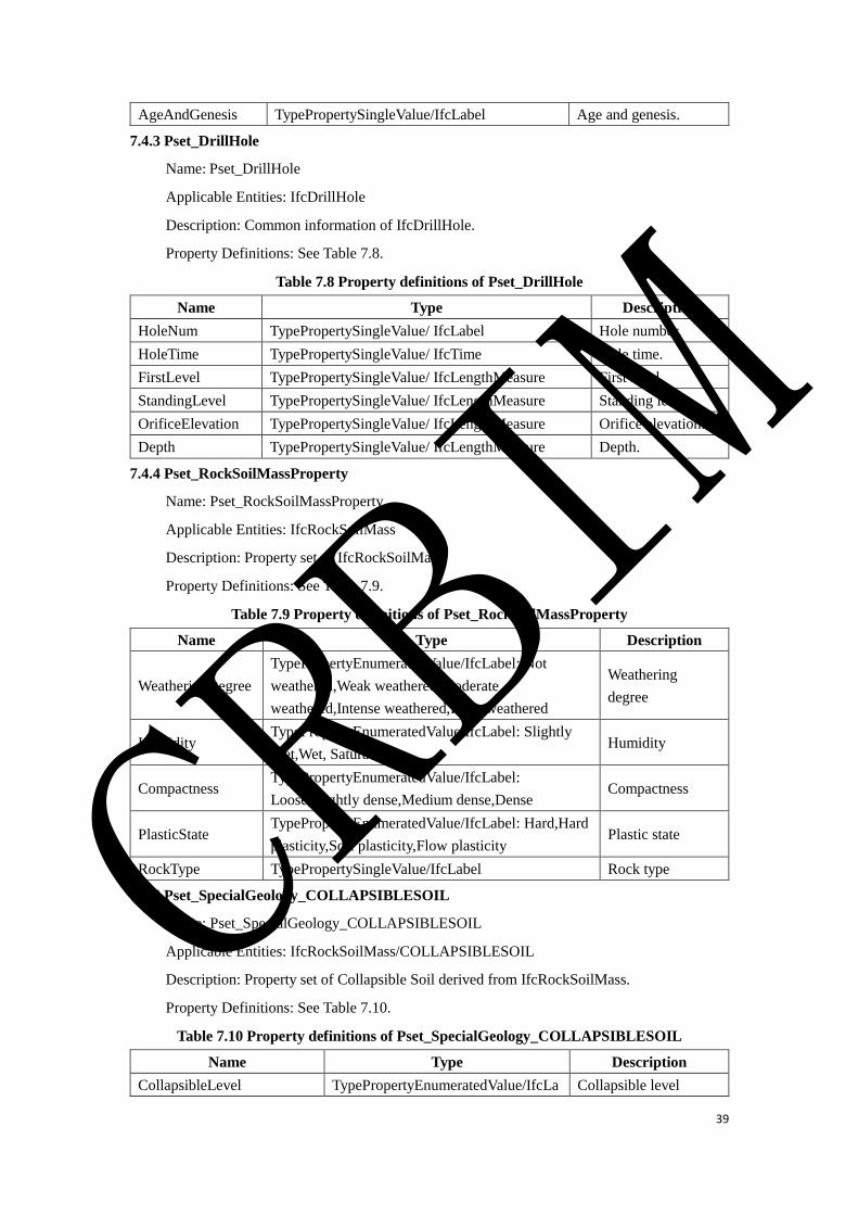
39
AgeAndGenesis TypePropertySingleValue/IfcLabel Age and genesis.
7.4.3 Pset_DrillHole
Name: Pset_DrillHole
Applicable Entities: IfcDrillHole
Description: Common information of IfcDrillHole.
Property Definitions: See Table 7.8.
Table 7.8 Property definitions of Pset_DrillHole
Name Type Description
HoleNum TypePropertySingleValue/ IfcLabel Hole number.
HoleTime TypePropertySingleValue/ IfcTime Hole time.
FirstLevel TypePropertySingleValue/ IfcLengthMeasure First level.
StandingLevel TypePropertySingleValue/ IfcLengthMeasure Standing level.
OrificeElevation TypePropertySingleValue/ IfcLengthMeasure Orifice elevation.
Depth TypePropertySingleValue/ IfcLengthMeasure Depth.
7.4.4 Pset_RockSoilMassProperty
Name: Pset_RockSoilMassProperty
Applicable Entities: IfcRockSoilMass
Description: Property set of IfcRockSoilMass.
Property Definitions: See Table 7.9.
Table 7.9 Property definitions of Pset_RockSoilMassProperty
Name Type Description
WeatheringDegree
TypePropertyEnumeratedValue/IfcLabel: Not
weathered,Weak weathered,Moderate
weathered,Intense weathered,Fully weathered
Weathering
degree
Humidity TypePropertyEnumeratedValue/IfcLabel: Slightly
Wet,Wet, Saturated Humidity
Compactness TypePropertyEnumeratedValue/IfcLabel:
Loose,Slightly dense,Medium dense,Dense Compactness
PlasticState TypePropertyEnumeratedValue/IfcLabel: Hard,Hard
plasticity,Soft plasticity,Flow plasticity Plastic state
RockType TypePropertySingleValue/IfcLabel Rock type
7.4.5 Pset_SpecialGeology_COLLAPSIBLESOIL
Name: Pset_SpecialGeology_COLLAPSIBLESOIL
Applicable Entities: IfcRockSoilMass/COLLAPSIBLESOIL
Description: Property set of Collapsible Soil derived from IfcRockSoilMass.
Property Definitions: See Table 7.10.
Table 7.10 Property definitions of Pset_SpecialGeology_COLLAPSIBLESOIL
Name Type Description
CollapsibleLevel TypePropertyEnumeratedValue/IfcLa Collapsible level
CRBIM
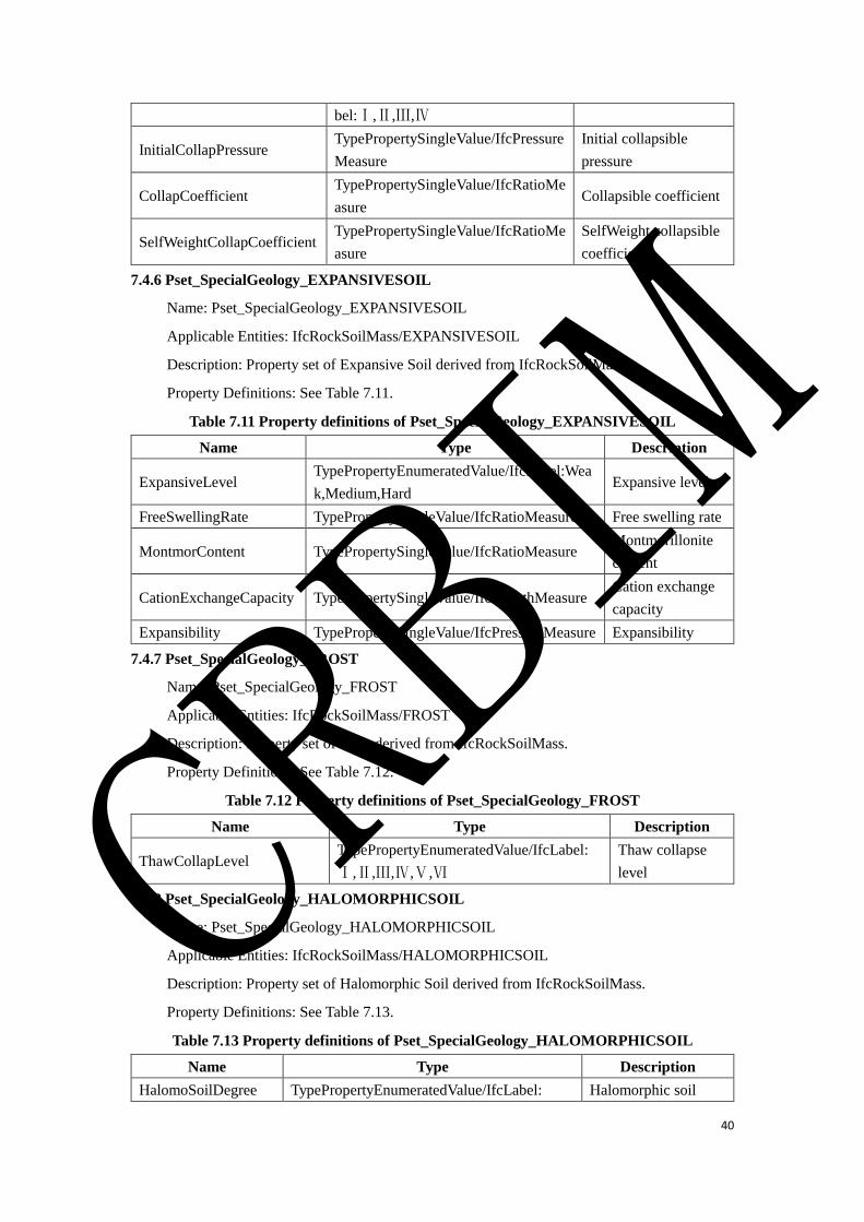
40
bel:Ⅰ,Ⅱ,Ⅲ,Ⅳ
InitialCollapPressure TypePropertySingleValue/IfcPressure
Measure
Initial collapsible
pressure
CollapCoefficient TypePropertySingleValue/IfcRatioMe
asure Collapsible coefficient
SelfWeightCollapCoefficient TypePropertySingleValue/IfcRatioMe
asure
SelfWeight collapsible
coefficient
7.4.6 Pset_SpecialGeology_EXPANSIVESOIL
Name: Pset_SpecialGeology_EXPANSIVESOIL
Applicable Entities: IfcRockSoilMass/EXPANSIVESOIL
Description: Property set of Expansive Soil derived from IfcRockSoilMass.
Property Definitions: See Table 7.11.
Table 7.11 Property definitions of Pset_SpecialGeology_EXPANSIVESOIL
Name Type Description
ExpansiveLevel TypePropertyEnumeratedValue/IfcLabel:Wea
k,Medium,Hard Expansive level
FreeSwellingRate TypePropertySingleValue/IfcRatioMeasure Free swelling rate
MontmorContent TypePropertySingleValue/IfcRatioMeasure Montmorillonite
content
CationExchangeCapacity TypePropertySingleValue/IfcLengthMeasure Cation exchange
capacity
Expansibility TypePropertySingleValue/IfcPressureMeasure Expansibility
7.4.7 Pset_SpecialGeology_FROST
Name: Pset_SpecialGeology_FROST
Applicable Entities: IfcRockSoilMass/FROST
Description: Property set of Frost derived from IfcRockSoilMass.
Property Definitions: See Table 7.12.
Table 7.12 Property definitions of Pset_SpecialGeology_FROST
Name Type Description
ThawCollapLevel TypePropertyEnumeratedValue/IfcLabel:
Ⅰ,Ⅱ,Ⅲ,Ⅳ,Ⅴ,Ⅵ
Thaw collapse
level
7.4.8 Pset_SpecialGeology_HALOMORPHICSOIL
Name: Pset_SpecialGeology_HALOMORPHICSOIL
Applicable Entities: IfcRockSoilMass/HALOMORPHICSOIL
Description: Property set of Halomorphic Soil derived from IfcRockSoilMass.
Property Definitions: See Table 7.13.
Table 7.13 Property definitions of Pset_SpecialGeology_HALOMORPHICSOIL
Name Type Description
HalomoSoilDegree TypePropertyEnumeratedValue/IfcLabel: Halomorphic soil
CRBIM

41
Weak,Medium,Hard,Super degree
7.4.9 Pset_SpecialGeology_POLLUTIONSOIL
Name: Pset_SpecialGeology_POLLUTIONSOIL
Applicable Entities: IfcRockSoilMass/ POLLUTIONSOIL
Description: Property set of Pollution Soil derived from IfcRockSoilMass.
Property Definitions: See Table 7.14.
Table 7.14 Property definitions of Pset_SpecialGeology_POLLUTIONSOIL
Name Type Description
ImpactLevel TypePropertyEnumeratedValue/IfcLabel Impact level.
7.4.10 Pset_GeologyDisaster_LANDSLIDE
Name: Pset_GeologyDisaster_LANDSLIDE
Applicable Entities: IfcRockSoilMass/LANDSLIDE
Description: Property set of Landslide derived from IfcRockSoilMass.
Property Definitions: See Table 7.15.
Table 7.15 Property definitions of Pset_GeologyDisaster_LANDSLIDE
Name Type Description
LandslideScale TypePropertyEnumeratedValue/IfcLabel: Small Scale,
Medium Scale, Big Scale, Super Scale Landslide scale.
7.4.11 Pset_GeologyDisaster_DEBRISFLOW
Name: Pset_GeologyDisaster_DEBRISFLOW
Applicable Entities: IfcRockSoilMass/DEBRISFLOW
Description: Property set of debris flow derived from IfcRockSoilMass.
Property Definitions: See Table 7.16.
Table 7.16 Property definitions of Pset_GeologyDisaster_DEBRISFLOW
Name Type Description
DebrisFlowScale TypePropertyEnumeratedValue/IfcLabel: Small
Scale, Medium Scale, Big Scale, Super Scale Debrisflow scale.
7.4.12 Pset_GeologyDisaster_KARST
Name: Pset_GeologyDisaster_KARST
Applicable Entities: IfcRockSoilMass/KARST
Description: Property set of karst derived from IfcRockSoilMass.
Property Definitions: See Table 7.17.
Table 7.17 Property definitions of Pset_GeologyDisaster_KARST
Name Type Description
KarstLevel TypePropertyEnumeratedValue/IfcLabel: Strong Development,
Medium Devlopment, Weak Development, Tiny Development Karst level.
7.4.13 Pset_GeologyDisaster_GOB
Name: Pset_GeologyDisaster_GOB
CRBIM
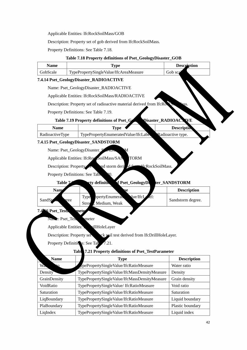
42
Applicable Entities: IfcRockSoilMass/GOB
Description: Property set of gob derived from IfcRockSoilMass.
Property Definitions: See Table 7.18.
Table 7.18 Property definitions of Pset_GeologyDisaster_GOB
Name Type Description
GobScale TypePropertySingleValue/IfcAreaMeasure Gob scale.
7.4.14 Pset_GeologyDisaster_RADIOACTIVE
Name: Pset_GeologyDisaster_RADIOACTIVE
Applicable Entities: IfcRockSoilMass/RADIOACTIVE
Description: Property set of radioactive material derived from IfcRockSoilMass.
Property Definitions: See Table 7.19.
Table 7.19 Property definitions of Pset_GeologyDisaster_RADIOACTIVE
Name Type Description
RadioactiveType TypePropertyEnumeratedValue/IfcLabel Radioactive type.
7.4.15 Pset_GeologyDisaster_SANDSTORM
Name: Pset_GeologyDisaster_SANDSTORM
Applicable Entities: IfcRockSoilMass/SANDSTORM
Description: Property set of sand storm derived from IfcRockSoilMass.
Property Definitions: See Table 7.20.
Table 7.20 Property definitions of Pset_GeologyDisaster_SANDSTORM
Name Type Description
SandStormDegree TypePropertyEnumeratedValue/IfcLabel:
Strong, Medium, Weak Sandstorm degree.
7.4.16 Pset_TestParameter
Name: Pset_TestParameter
Applicable Entities: IfcDrillHoleLayer
Description: Property set of rock soil test derived from IfcDrillHoleLayer.
Property Definitions: See Table 7.21.
Table 7.21 Property definitions of Pset_TestParameter
Name Type Description
WaterRatio TypePropertySingleValue/IfcRatioMeasure Water ratio
Density TypePropertySingleValue/IfcMassDensityMeasure Density
GrainDensity TypePropertySingleValue/IfcMassDensityMeasure Grain density
VoidRatio TypePropertySingleValue/ IfcRatioMeasure Void ratio
Saturation TypePropertySingleValue/IfcRatioMeasure Saturation
LiqBoundary TypePropertySingleValue/IfcRatioMeasure Liquid boundary
PlaBoundary TypePropertySingleValue/IfcRatioMeasure Plastic boundary
LiqIndex TypePropertySingleValue/IfcRatioMeasure Liquid index
CRBIM

43
PlaIndex TypePropertySingleValue/IfcRatioMeasure Plastic index
CompreCoefficient TypePropertySingleValue/IfcLengthMeasure Coefficient of
compressibility
PreModulus TypePropertySingleValue/IfcPressureMeasure Compression
modulus
InterFricAngle TypePropertySingleValue/ IfcPlaneAngleMeasure Interfriction Angle
Cohesion TypePropertySingleValue/ IfcPressureMeasure Cohesion
AntiPressStren TypePropertySingleValue/ IfcPressureMeasure Anti press strength
8.Subgrade Schema
8.1 Schema Definition
The data model architecture of railway subgrade is composed of IfcSubgradeStructureElement,
IfcSubgradeElementAssembly and IfcSubgradeElement.
IfcSubgradeStructureElement mainly includes IfcSubgradeStructurePartElement,
IfcSubgradeSlopeProtectionElement, IfcSubgradeRetainingStructureElement,
IfcSubgradeSubsoilTreatmentElement and IfcSubgradeTransitionSectionStructureElement.
IfcSubgradeElementAssembly mainly includes
IfcSubgradeRetainingStructureSectionAssembly and
IfcSubgradeSubsoilReinforcementPileAssembly.
IfcSubgradeElement mainly includes IfcSubgradeRetainingElement,
IfcSubgradeFillingWorks, IfcSubgradeSlopeProtectionSectionElement,
IfcSubgradeSubsoilReinforcementPileElement, IfcOriginalSubgradeSubsoilReinforcement and
IfcSubgradeTransitionSectionElement.
Figure 8.1 shows the relationship between IfcSubgradeStructureElement,
IfcSubgradeElementAssembly and IfcSubgradeElement.
CRBIM
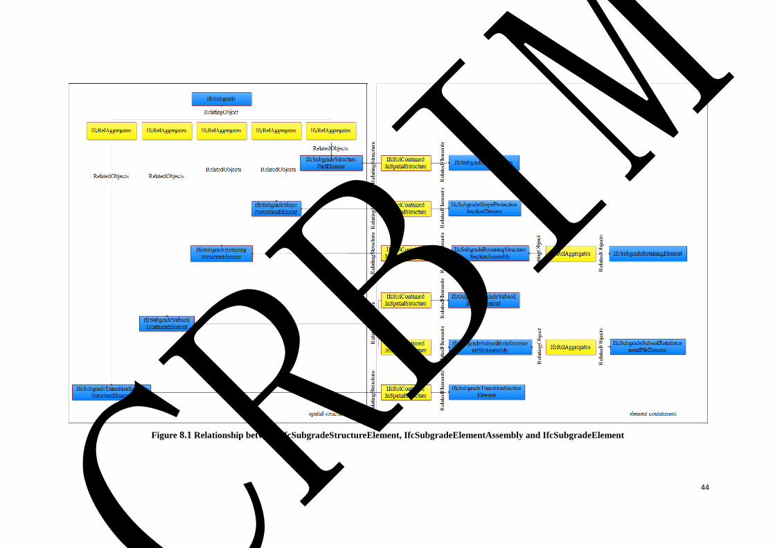
44
Figure 8.1 Relationship between IfcSubgradeStructureElement, IfcSubgradeElementAssembly and IfcSubgradeElement
CRBIM
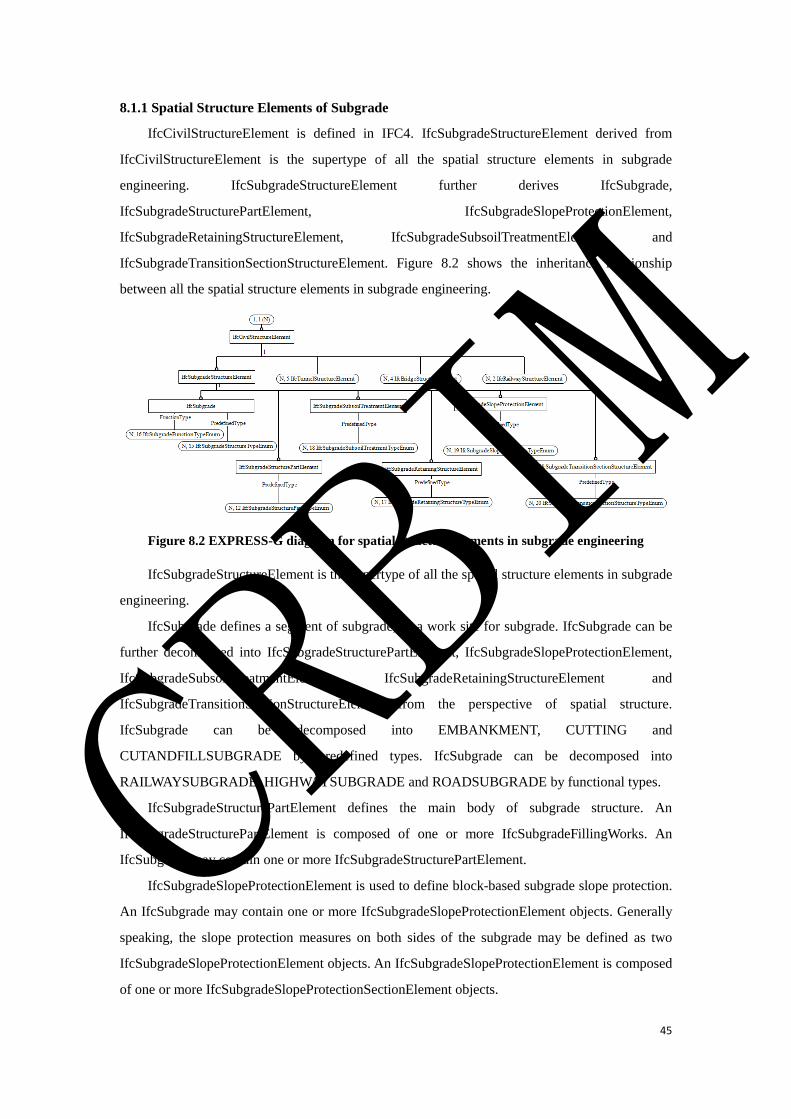
45
8.1.1 Spatial Structure Elements of Subgrade
IfcCivilStructureElement is defined in IFC4. IfcSubgradeStructureElement derived from
IfcCivilStructureElement is the supertype of all the spatial structure elements in subgrade
engineering. IfcSubgradeStructureElement further derives IfcSubgrade,
IfcSubgradeStructurePartElement, IfcSubgradeSlopeProtectionElement,
IfcSubgradeRetainingStructureElement, IfcSubgradeSubsoilTreatmentElement and
IfcSubgradeTransitionSectionStructureElement. Figure 8.2 shows the inheritance relationship
between all the spatial structure elements in subgrade engineering.
Figure 8.2 EXPRESS-G diagram for spatial structure elements in subgrade engineering
IfcSubgradeStructureElement is the supertype of all the spatial structure elements in subgrade
engineering.
IfcSubgrade defines a segment of subgrade, or a work site for subgrade. IfcSubgrade can be
further decomposed into IfcSubgradeStructurePartElement, IfcSubgradeSlopeProtectionElement,
IfcSubgradeSubsoilTreatmentElement, IfcSubgradeRetainingStructureElement and
IfcSubgradeTransitionSectionStructureElement from the perspective of spatial structure.
IfcSubgrade can be decomposed into EMBANKMENT, CUTTING and
CUTANDFILLSUBGRADE by predefined types. IfcSubgrade can be decomposed into
RAILWAYSUBGRADE, HIGHWAYSUBGRADE and ROADSUBGRADE by functional types.
IfcSubgradeStructurePartElement defines the main body of subgrade structure. An
IfcSubgradeStructurePartElement is composed of one or more IfcSubgradeFillingWorks. An
IfcSubgrade may contain one or more IfcSubgradeStructurePartElement.
IfcSubgradeSlopeProtectionElement is used to define block-based subgrade slope protection.
An IfcSubgrade may contain one or more IfcSubgradeSlopeProtectionElement objects. Generally
speaking, the slope protection measures on both sides of the subgrade may be defined as two
IfcSubgradeSlopeProtectionElement objects. An IfcSubgradeSlopeProtectionElement is composed
of one or more IfcSubgradeSlopeProtectionSectionElement objects.
CRBIM
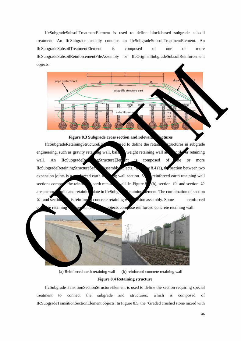
46
IfcSubgradeSubsoilTreatmentElement is used to define block-based subgrade subsoil
treatment. An IfcSubgrade usually contains an IfcSubgradeSubsoilTreatmentElement. An
IfcSubgradeSubsoilTreatmentElement is composed of one or more
IfcSubgradeSubsoilReinforcementPileAssembly or IfcOriginalSubgradeSubsoilReinforcement
objects.
Figure 8.3 Subgrade cross section and relevant structures
IfcSubgradeRetainingStructureElement is used to define the retaining structures in subgrade
engineering, such as gravity retaining wall, balance weight retaining wall and cantilever retaining
wall. An IfcSubgradeRetainingStructureElement is composed of one or more
IfcSubgradeRetainingStructureSectionAssembly objects. In Figure 8.4 (a), the section between two
expansion joints is a reinforced earth retaining wall section. Some reinforced earth retaining wall
sections compose the reinforced earth retaining wall. In Figure 8.4 (b), section ○1 and section ○2
are anchorage pile and retaining plate in IfcSubgradeRetainingElement. The combination of section
○1 and section ○2 is reinforced concrete retaining wall section assembly. Some reinforced
concrete retaining wall section assembly objects compose reinforced concrete retaining wall.
(a) Reinforced earth retaining wall (b) reinforced concrete retaining wall
Figure 8.4 Retaining structure
IfcSubgradeTransitionSectionStructureElement is used to define the section requiring special
treatment to connect the subgrade and structures, which is composed of
IfcSubgradeTransitionSectionElement objects. In Figure 8.5, the "Graded crushed stone mixed with
slope protection 1
subgrade structure part
slope protection 2
subsoil treatment
① ② CRBIM
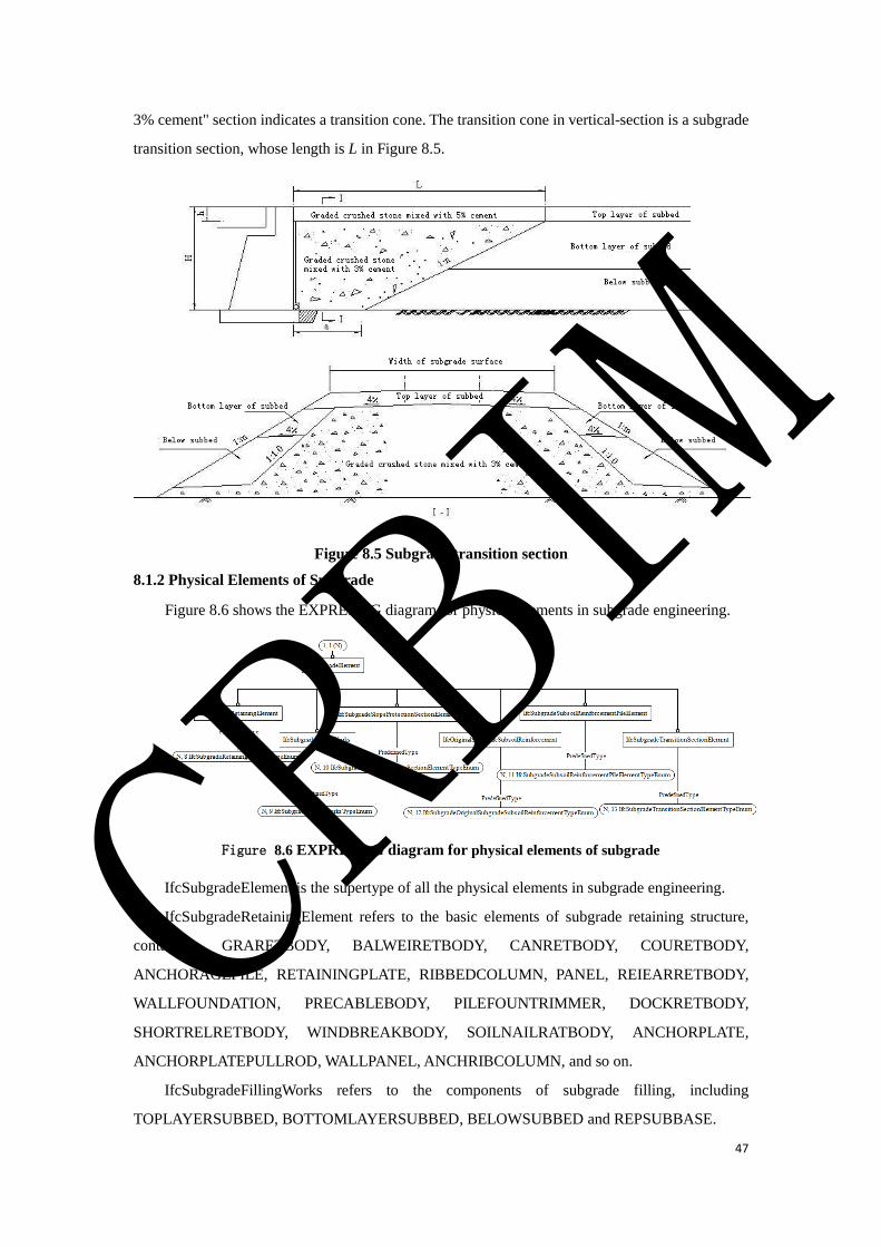
47
3% cement" section indicates a transition cone. The transition cone in vertical-section is a subgrade
transition section, whose length is L in Figure 8.5.
Figure 8.5 Subgrade transition section
8.1.2 Physical Elements of Subgrade
Figure 8.6 shows the EXPRESS-G diagram for physical elements in subgrade engineering.
Figure 8.6 EXPRESS-G diagram for physical elements of subgrade
IfcSubgradeElement is the supertype of all the physical elements in subgrade engineering.
IfcSubgradeRetainingElement refers to the basic elements of subgrade retaining structure,
containing GRARETBODY, BALWEIRETBODY, CANRETBODY, COURETBODY,
ANCHORAGEPILE, RETAININGPLATE, RIBBEDCOLUMN, PANEL, REIEARRETBODY,
WALLFOUNDATION, PRECABLEBODY, PILEFOUNTRIMMER, DOCKRETBODY,
SHORTRELRETBODY, WINDBREAKBODY, SOILNAILRATBODY, ANCHORPLATE,
ANCHORPLATEPULLROD, WALLPANEL, ANCHRIBCOLUMN, and so on.
IfcSubgradeFillingWorks refers to the components of subgrade filling, including
TOPLAYERSUBBED, BOTTOMLAYERSUBBED, BELOWSUBBED and REPSUBBASE.
CRBIM
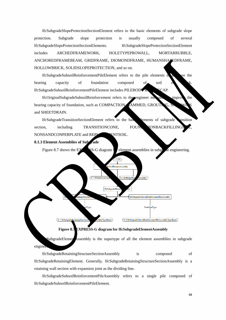
48
IfcSubgradeSlopeProtectionSectionElement refers to the basic elements of subgrade slope
protection. Subgrade slope protection is usually composed of several
IfcSubgradeSlopeProtectionSectionElements. IfcSubgradeSlopeProtectionSectionElement
includes ARCHEDFRAMEWORK, HOLETYPEPROWALL, MORTARRUBBLE,
ANCHOREDFRAMEBEAM, GRIDFRAME, DIOMONDFRAME, HUMANSHAPEDFRAME,
HOLLOWBRICK, SOLIDSLOPEPROTECTION, and so on.
IfcSubgradeSubsoilReinforcementPileElement refers to the pile elements to improve the
bearing capacity of foundation composed of soil or rock.
IfcSubgradeSubsoilReinforcementPileElement includes PILEBODY and PILECAP.
IfcOriginalSubgradeSubsoilReinforcement refers to the engineer measures to improve the
bearing capacity of foundation, such as COMPACTION, RAMMED, GROUTING, SANDWICK
and SHEETDRAIN.
IfcSubgradeTransitionSectionElement refers to the basic elements of subgrade transition
section, including TRANSITIONCONE, FOUNDATIONBACKFILLINGSOIL,
NONSANDCONPERPLATE and REPLACEMENTSOIL.
8.1.3 Element Assemblies of Subgrade
Figure 8.7 shows the EXPRESS-G diagram for element assemblies in subgrade engineering.
Figure 8.7 EXPRESS-G diagram for IfcSubgradeElementAssembly
IfcSubgradeElementAssembly is the supertype of all the element assemblies in subgrade
engineering.
IfcSubgradeRetainingStructureSectionAssembly is composed of
IfcSubgradeRetainingElement. Generally, IfcSubgradeRetainingStructureSectionAssembly is a
retaining wall section with expansion joint as the dividing line.
IfcSubgradeSubsoilReinforcementPileAssembly refers to a single pile composed of
IfcSubgradeSubsoilReinforcementPileElement.
CRBIM

49
8.2 Type Definition
8.2.1 IfcSubgradeStructureTypeEnum
This enumeration defines the different predefined types of subgrade from the perspective of
form.
Enumerated Item Definitions:
EMBANKMENT;
CUTTING;
CUTANDFILLSUBGRADE;
USERDEFINED;
NOTDEFINED.
EXPRESS Specification:
TYPE IfcSubgradeStructureTypeEnum = ENUMERATION OF
(EMBANKMENT
, CUTTING
, CUTANDFILLSUBGRADE
, USERDEFINED
, NOTDEFINED
);
END_TYPE;
8.2.2 IfcSubgradeFunctionTypeEnum
This enumeration defines the different functional types of subgrade.
Enumerated Item Definitions:
RAILWAYSUBGRADE;
HIGHWAYSUBGRADE;
ROADSUBGRADE;
USERDEFINED;
NOTDEFINED.
EXPRESS Specification:
TYPE IfcSubgradeFunctionTypeEnum = ENUMERATION OF
(RAILWAYSUBGRADE
, HIGHWAYSUBGRADE
, ROADSUBGRADE
, USERDEFINED
, NOTDEFINED
);
END_TYPE;
8.2.3 IfcSubgradeStructurePartTypeEnum
CRBIM

50
This enumeration defines the different predefined types of an
IfcSubgradeStructurePartElement.
Enumerated Item Definitions:
USERDEFINED;
NOTDEFINED.
EXPRESS Specification:
TYPE IfcSubgradeStructurePartTypeEnum = ENUMERATION OF
( USERDEFINED
, NOTDEFINED
);
END_TYPE;
8.2.4 IfcSubgradeSlopeProtectionTypeEnum
This enumeration defines the different predefined types of an
IfcSubgradeSlopeProtectionElement.
Enumerated Item Definitions:
USERDEFINED;
NOTDEFINED.
EXPRESS Specification:
TYPE IfcSubgradeSlopeProtectionTypeEnum = ENUMERATION OF
( USERDEFINED
, NOTDEFINED
);
END_TYPE;
8.2.5 IfcSubgradeRetainingStructureTypeEnum
This enumeration defines the different predefined types of an
IfcSubgradeRetainingStructureElement.
Enumerated Item Definitions:
GRARETWALL;
BALWEIRETWALL;
CANRETWALL;
COURETWALL;
REICONRETWALL;
ANCBOLTRETWALL;
REIEARRETWALL;
PRECABLE;
CRBIM

51
PILEFOUNRETWALL;
DOCKRETWALL;
SHORTRELRETWALL;
WINDBREAKWALL;
SOILNAILRATWALL;
ANCPLARETWALL;
USERDEFINED;
NOTDEFINED.
EXPRESS Specification:
TYPE IfcSubgradeRetainingStructureTypeEnum = ENUMERATION OF
(GRARETWALL
,BALWEIRETWALL
,CANRETWALL
,COURETWALL
,REICONRETWALL
,ANCBOLTRETWALL
,REIEARRETWALL
,PRECABLE
,PILEFOUNRETWALL
,DOCKRETWALL
,SHORTRELRETWALL
,WINDBREAKWALL
,SOILNAILRATWALL
,ANCPLARETWALL
,USERDEFINED
,NOTDEFINED
);
END_TYPE;
8.2.6 IfcSubgradeSubsoilTreatmentTypeEnum
This enumeration defines the different predefined types of an
IfcSubgradeSubsoilTreatmentElement.
Enumerated Item Definitions:
USERDEFINED;
NOTDEFINED.
EXPRESS Specification:
TYPE IfcSubgradeSubsoilTreatmentTypeEnum = ENUMERATION OF
( USERDEFINED
, NOTDEFINED
CRBIM

52
);
END_TYPE;
8.2.7 IfcSubgradeTransitionSectionStructureTypeEnum
This enumeration defines the different predefined types of an
IfcSubgradeTransitionSectionStructureElement.
Enumerated Item Definitions:
EMBANKMENTABUTMENT;
MBANKMENTLATERALSTRUCTURE; EMBANKMENTCUTTING;
CUTTINGABUTMENT;
CUTTINGTUNNEL;
USERDEFINED;
NOTDEFINED.
EXPRESS Specification:
TYPE IfcSubgradeTransitionSectionStructureTypeEnum = ENUMERATION OF
(EMBANKMENTABUTMENT
,EMBANKMENTLATERALSTRUCTURE
,EMBANKMENTCUTTING
,CUTTINGABUTMENT
,CUTTINGTUNNEL
,USERDEFINED
, NOTDEFINED
);
END_TYPE;
8.2.8 IfcSubgradeRetainingElementTypeEnum
This enumeration defines the different predefined types of an IfcSubgradeRetainingElement.
Enumerated Item Definitions:
GRARETBODY;
BALWEIRETBODY;
CANRETBODY;
COURETBODY;
ANCHORAGEPILE;
RETAININGPLATE;
RIBBEDCOLUMN;
PANEL;
REIEARRETBODY;
WALLFOUNDATION;
PRECABLEBODY;
CRBIM

53
PILEFOUNTRIMMER;
DOCKRETBODY;
SHORTRELRETBODY;
WINDBREAKBODY;
SOILNAILRATBODY;
ANCHORPLATE;
ANCHORPLATEPULLROD;
WALLPANEL;
ANCHRIBCOLUMN;
USERDEFINED;
NOTDEFINED.
EXPRESS Specification:
TYPE IfcSubgradeRetainingElementTypeEnum = ENUMERATION OF
(GRARETBODY
,BALWEIRETBODY
,CANRETBODY
,COURETBODY
,ANCHORAGEPILE
,RETAININGPLATE
,RIBBEDCOLUMN
,PANEL
,REIEARRETBODY
,WALLFOUNDATION
,PRECABLEBODY
,PILEFOUNTRIMMER
,DOCKRETBODY
,SHORTRELRETBODY
,WINDBREAKBODY
,SOILNAILRATBODY
,ANCHORPLATE
,ANCHORPLATEPULLROD
,WALLPANEL
,ANCHRIBCOLUMN
,USERDEFINED
, NOTDEFINED
);
END_TYPE;
8.2.9 IfcSubgradeFillingWorksTypeEnum
This enumeration defines the different predefined types of an IfcSubgradeFillingWorks.
CRBIM

54
Enumerated Item Definitions:
TOPLAYERSUBBED;
BOTTOMLAYERSUBBED;
BELOWSUBBED;
REPSUBBASE;
USERDEFINED;
NOTDEFINED.
EXPRESS Specification:
TYPE IfcSubgradeFillingWorksTypeEnum = ENUMERATION OF
(TOPLAYERSUBBED
,BOTTOMLAYERSUBBED
,BELOWSUBBED
,REPSUBBASE
,USERDEFINED
, NOTDEFINED
);
END_TYPE;
8.2.10 IfcSubgradeSlopeProtectionSectionElementTypeEnum
This enumeration defines the different predefined types of an
IfcSubgradeSlopeProtectionSectionElement.
Enumerated Item Definitions:
ARCHEDFRAMEWORK;
HOLETYPEPROWALL;
MORTARRUBBLE;
ANCHOREDFRAMEBEAM;
GRIDFRAME;
DIOMONDFRAME;
HUMANSHAPEDFRAME;
HOLLOWBRICK;
SOLIDSLOPEPROTECTION;;
USERDEFINED;
NOTDEFINED.
EXPRESS Specification:
TYPE IfcSubgradeSlopeProtectionSectionElementTypeEnum = ENUMERATION OF
(ARCHEDFRAMEWORK
,HOLETYPEPROWALL
CRBIM
55
,MORTARRUBBLE
,ANCHOREDFRAMEBEAM
,GRIDFRAME
,DIOMONDFRAME
,HUMANSHAPEDFRAME
,HOLLOWBRICK
,SOLIDSLOPEPROTECTION
,USERDEFINED
,NOTDEFINED
);
END_TYPE;
8.2.11 IfcSubgradeSubsoilReinforcementPileElementTypeEnum
This enumeration defines the different predefined types of an
IfcSubgradeSubsoilReinforcementPileElement.
Enumerated Item Definitions:
PILECAP;
PILEBODY;
USERDEFINED;
NOTDEFINED.
EXPRESS Specification:
TYPE IfcSubgradeSubsoilReinforcementPileElementTypeEnum = ENUMERATION OF
(PILECAP
,PILEBODY
,USERDEFINED
, NOTDEFINED
);
END_TYPE;
8.2.12 IfcSubgradeOriginalSubgradeSubsoilReinforcementTypeEnum
This enumeration defines the different predefined types of an
IfcSubgradeOriginalSubgradeSubsoilReinforcement.
Enumerated Item Definitions:
COMPACTION;
RAMMED;
GROUTING;
SANDWICK;
SHEETDRAIN;
USERDEFINED;
NOTDEFINED.
CRBIM

56
EXPRESS Specification:
TYPE IfcSubgradeOriginalSubgradeSubsoilReinforcementTypeEnum = ENUMERATION OF
(COMPACTION
,RAMMED
,GROUTING
,SANDWICK
,SHEETDRAIN
,USERDEFINED
, NOTDEFINED
);
END_TYPE;
8.2.13 IfcSubgradeTransitionSectionElementTypeEnum
This enumeration defines the different predefined types of an
IfcSubgradeTransitionSectionElement.
Enumerated Item Definitions:
TRANSITIONCONE;
FOUNDATIONBACKFILLINGSOIL;
NONSANDCONPERPLATE;
REPLACEMENTSOIL;
USERDEFINED;
NOTDEFINED.
EXPRESS Specification:
TYPE IfcSubgradeTransitionSectionElementTypeEnum= ENUMERATION OF
(TRANSITIONCONE
,FOUNDATIONBACKFILLINGSOIL
,NONSANDCONPERPLATE
,REPLACEMENTSOIL
,USERDEFINED
, NOTDEFINED
);
END_TYPE;
8.2.14 IfcSubgradeRetainingStructureSectionAssemblyTypeEnum
This enumeration defines the different predefined types of an
IfcSubgradeRetainingStructureSectionAssembly.
Enumerated Item Definitions:
GRARETSECTION;
BALWEIRETSECTION;
CRBIM

57
CANRETSECTION;
COURETSECTION;
REICONRETSECTION;
ANCBOLTRETSECTION;
REIEARRETSECTION;
PRECABLESECTION;
PILEFOUNRETSECTION;
DOCKRETSECTION;
SHORTRELRETSECTION;
WINDBREAKSECTION;
SOILNAILRATSECTION;
ANCPLARETSECTION;
USERDEFINED;
NOTDEFINED.
EXPRESS Specification:
TYPE IfcSubgradeRetainingStructureSectionAssemblyTypeEnum= ENUMERATION OF
(GRARETSECTION
,BALWEIRETSECTION
,CANRETSECTION
,COURETSECTION
,REICONRETSECTION
,ANCBOLTRETSECTION
,REIEARRETSECTION
,PRECABLESECTION
,PILEFOUNRETSECTION
,DOCKRETSECTION
,SHORTRELRETSECTION
,WINDBREAKSECTION
,SOILNAILRATSECTION
,ANCPLARETSECTION
,USERDEFINED
,NOTDEFINED
);
END_TYPE;
8.2.15 IfcSubgradeSubsoilReinforcementPileAssemblyTypeEnum
This enumeration defines the different predefined types of an
IfcSubgradeSubsoilReinforcementPileAssembly.
Enumerated Item Definitions:
CRBIM
58
CEMENTMIXINGPILE;
LIMESOILCOMPILE;
CEMFLYGRAPILE;
CHEMICALCHURNINGPILE;
COLUMNHAMEXPPILE;
CEMSOILCOMPPILE;
USERDEFINED;
NOTDEFINED.
EXPRESS Specification:
TYPE IfcSubgradeSubsoilReinforcementPileAssemblyTypeEnum= ENUMERATION OF
(CEMENTMIXINGPILE
,LIMESOILCOMPILE
,CEMFLYGRAPILE
,CHEMICALCHURNINGPILE
,COLUMNHAMEXPPILE
,CEMSOILCOMPPILE
,USERDEFINED
,NOTDEFINED
);
END_TYPE;
8.3 Entity Definition
8.3.1 IfcSubgradeStructureElement
IfcSubgradeStructureElement is the supertype of all the spatial structure elements in subgrade
engineering.
EXPRESS Specification:
ENTITY IfcSubgradeStructureElement
SUPERTYPE OF (ONEOF
(IfcSubgrade,IfcSubgradeStructurePartElement,IfcSubgradeSlopeProtectionElement,IfcSubgradeRetai
ningStructureElement,IfcSubgradeSubsoilTreatmentElement,IfcSubgradeTransitionSectionStructureElement)
SUBTYPE OF (IfcCivilStructureElement);
END_ENTITY;
8.3.2 IfcSubgrade
IfcSubgrade refers to a segment of subgrade with certain functions, clear start point and end
point.
Table 8.1 IfcSubgrade spatial composition
Spatial Composite Description
IfcRailway IfcSubgrade can be a component of IfcRailway.
IfcRailwayStation IfcSubgrade can be a component of IfcRailwayStation.
CRBIM
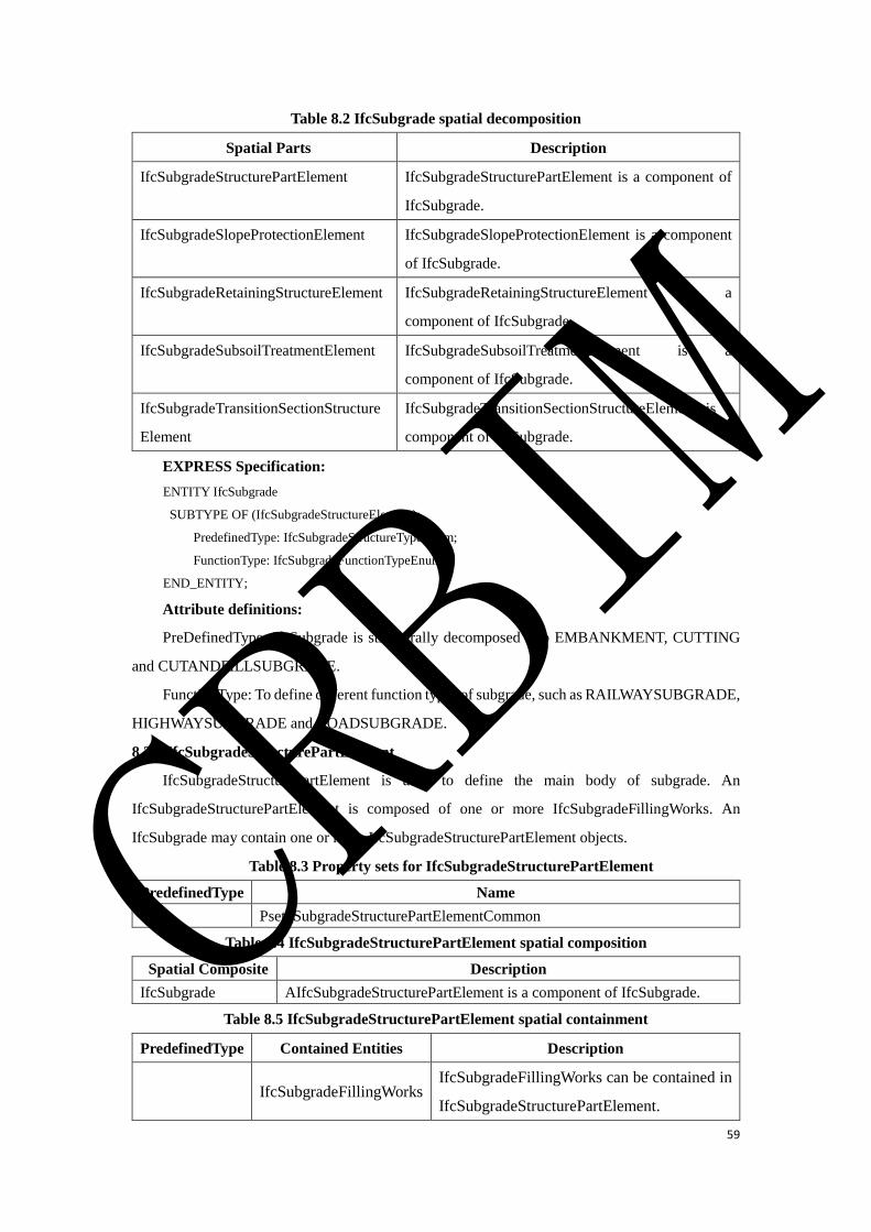
59
Table 8.2 IfcSubgrade spatial decomposition
Spatial Parts Description
IfcSubgradeStructurePartElement IfcSubgradeStructurePartElement is a component of
IfcSubgrade.
IfcSubgradeSlopeProtectionElement IfcSubgradeSlopeProtectionElement is a component
of IfcSubgrade.
IfcSubgradeRetainingStructureElement IfcSubgradeRetainingStructureElement is a
component of IfcSubgrade.
IfcSubgradeSubsoilTreatmentElement IfcSubgradeSubsoilTreatmentElement is a
component of IfcSubgrade.
IfcSubgradeTransitionSectionStructure
Element
IfcSubgradeTransitionSectionStructureElement is a
component of IfcSubgrade.
EXPRESS Specification:
ENTITY IfcSubgrade
SUBTYPE OF (IfcSubgradeStructureElement);
PredefinedType: IfcSubgradeStructureTypeEnum;
FunctionType: IfcSubgradeFunctionTypeEnum;
END_ENTITY;
Attribute definitions:
PreDefinedType: IfcSubgrade is structurally decomposed into EMBANKMENT, CUTTING
and CUTANDFILLSUBGRADE.
FunctionType: To define different function types of subgrade, such as RAILWAYSUBGRADE,
HIGHWAYSUBGRADE and ROADSUBGRADE.
8.3.3 IfcSubgradeStructurePartElement
IfcSubgradeStructurePartElement is used to define the main body of subgrade. An
IfcSubgradeStructurePartElement is composed of one or more IfcSubgradeFillingWorks. An
IfcSubgrade may contain one or more IfcSubgradeStructurePartElement objects.
Table 8.3 Property sets for IfcSubgradeStructurePartElement
PredefinedType Name
Pset_SubgradeStructurePartElementCommon
Table 8.4 IfcSubgradeStructurePartElement spatial composition
Spatial Composite Description
IfcSubgrade AIfcSubgradeStructurePartElement is a component of IfcSubgrade.
Table 8.5 IfcSubgradeStructurePartElement spatial containment
PredefinedType Contained Entities Description
IfcSubgradeFillingWorks
IfcSubgradeFillingWorks can be contained in
IfcSubgradeStructurePartElement.
CRBIM
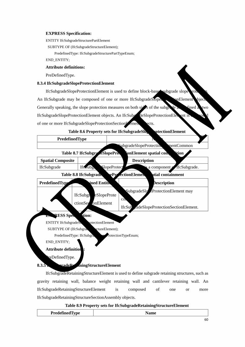
60
EXPRESS Specification:
ENTITY IfcSubgradeStructurePartElement
SUBTYPE OF (IfcSubgradeStructureElement);
PredefinedType: IfcSubgradeStructurePartTypeEnum;
END_ENTITY;
Attribute definitions:
PreDefinedType.
8.3.4 IfcSubgradeSlopeProtectionElement
IfcSubgradeSlopeProtectionElement is used to define block-based subgrade slope protection.
An IfcSubgrade may be composed of one or more IfcSubgradeSlopeProtectionElement objects.
Generally speaking, the slope protection measures on both sides of the subgrade are defined as two
IfcSubgradeSlopeProtectionElement objects. An IfcSubgradeSlopeProtectionElement is composed
of one or more IfcSubgradeSlopeProtectionSectionElement objects.
Table 8.6 Property sets for IfcSubgradeSlopeProtectionElement
PredefinedType Name
Pset_SubgradeSlopeProtectionElementCommon
Table 8.7 IfcSubgradeSlopeProtectionElement spatial composition
Spatial Composite Description
IfcSubgrade IfcSubgradeSlopeProtectionElement is a component of IfcSubgrade.
Table 8.8 IfcSubgradeSlopeProtectionElement spatial containment
PredefinedType Contained Entities Description
IfcSubgradeSlopeProte
ctionSectionElement
IfcSubgradeSlopeProtectionElement may
contain
IfcSubgradeSlopeProtectionSectionElement.
EXPRESS Specification:
ENTITY IfcSubgradeSlopeProtectionElement
SUBTYPE OF (IfcSubgradeStructureElement);
PredefinedType: IfcSubgradeSlopeProtectionTypeEnum;
END_ENTITY;
Attribute definitions:
PreDefinedType.
8.3.5 IfcSubgradeRetainingStructureElement
IfcSubgradeRetainingStructureElement is used to define subgrade retaining structures, such as
gravity retaining wall, balance weight retaining wall and cantilever retaining wall. An
IfcSubgradeRetainingStructureElement is composed of one or more
IfcSubgradeRetainingStructureSectionAssembly objects.
Table 8.9 Property sets for IfcSubgradeRetainingStructureElement
PredefinedType Name
CRBIM
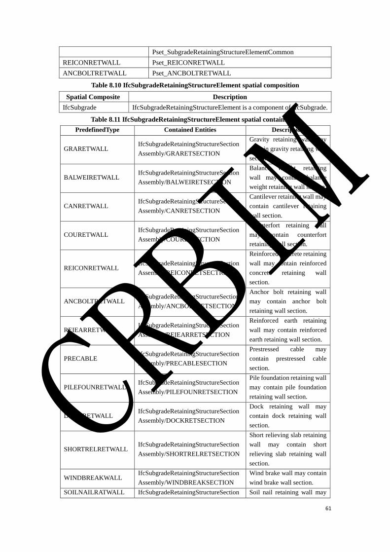
61
Pset_SubgradeRetainingStructureElementCommon
REICONRETWALL Pset_REICONRETWALL
ANCBOLTRETWALL Pset_ANCBOLTRETWALL
Table 8.10 IfcSubgradeRetainingStructureElement spatial composition
Spatial Composite Description
IfcSubgrade IfcSubgradeRetainingStructureElement is a component of IfcSubgrade.
Table 8.11 IfcSubgradeRetainingStructureElement spatial containment
PredefinedType Contained Entities Description
GRARETWALL IfcSubgradeRetainingStructureSection
Assembly/GRARETSECTION
Gravity retaining wall may
contain gravity retaining wall
section.
BALWEIRETWALL IfcSubgradeRetainingStructureSection
Assembly/BALWEIRETSECTION
Balance weight retaining
wall may contain balance
weight retaining wall section.
CANRETWALL IfcSubgradeRetainingStructureSection
Assembly/CANRETSECTION
Cantilever retaining wall may
contain cantilever retaining
wall section.
COURETWALL IfcSubgradeRetainingStructureSection
Assembly/COURETSECTION
Counterfort retaining wall
may contain counterfort
retaining wall section.
REICONRETWALL IfcSubgradeRetainingStructureSection
Assembly/REICONRETSECTION
Reinforced concrete retaining
wall may contain reinforced
concrete retaining wall
section.
ANCBOLTRETWALL IfcSubgradeRetainingStructureSection
Assembly/ANCBOLTRETSECTION
Anchor bolt retaining wall
may contain anchor bolt
retaining wall section.
REIEARRETWALL IfcSubgradeRetainingStructureSection
Assembly/REIEARRETSECTION
Reinforced earth retaining
wall may contain reinforced
earth retaining wall section.
PRECABLE IfcSubgradeRetainingStructureSection
Assembly/PRECABLESECTION
Prestressed cable may
contain prestressed cable
section.
PILEFOUNRETWALL IfcSubgradeRetainingStructureSection
Assembly/PILEFOUNRETSECTION
Pile foundation retaining wall
may contain pile foundation
retaining wall section.
DOCKRETWALL IfcSubgradeRetainingStructureSection
Assembly/DOCKRETSECTION
Dock retaining wall may
contain dock retaining wall
section.
SHORTRELRETWALL IfcSubgradeRetainingStructureSection
Assembly/SHORTRELRETSECTION
Short relieving slab retaining
wall may contain short
relieving slab retaining wall
section.
WINDBREAKWALL IfcSubgradeRetainingStructureSection
Assembly/WINDBREAKSECTION
Wind brake wall may contain
wind brake wall section.
SOILNAILRATWALL IfcSubgradeRetainingStructureSection Soil nail retaining wall may
CRBIM
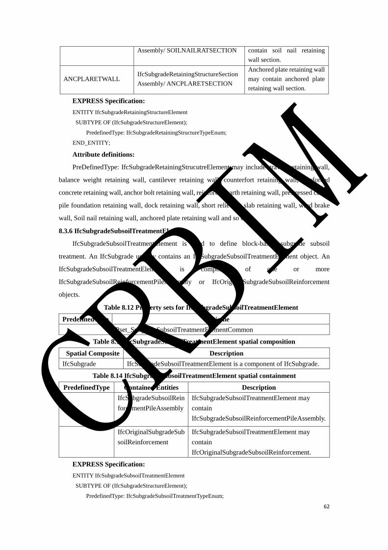
62
Assembly/ SOILNAILRATSECTION contain soil nail retaining
wall section.
ANCPLARETWALL IfcSubgradeRetainingStructureSection
Assembly/ ANCPLARETSECTION
Anchored plate retaining wall
may contain anchored plate
retaining wall section.
EXPRESS Specification:
ENTITY IfcSubgradeRetainingStructureElement
SUBTYPE OF (IfcSubgradeStructureElement);
PredefinedType: IfcSubgradeRetainingStructureTypeEnum;
END_ENTITY;
Attribute definitions:
PreDefinedType: IfcSubgradeRetainingStrucutreElement may include gravity retaining wall,
balance weight retaining wall, cantilever retaining wall, counterfort retaining wall, reinforced
concrete retaining wall, anchor bolt retaining wall, reinforced earth retaining wall, prestressed cable,
pile foundation retaining wall, dock retaining wall, short relieving slab retaining wall, wind brake
wall, Soil nail retaining wall, anchored plate retaining wall and so on.
8.3.6 IfcSubgradeSubsoilTreatmentElement
IfcSubgradeSubsoilTreatmentElement is used to define block-based subgrade subsoil
treatment. An IfcSubgrade usually contains an IfcSubgradeSubsoilTreatmentElement object. An
IfcSubgradeSubsoilTreatmentElement is composed of one or more
IfcSubgradeSubsoilReinforcementPileAssembly or IfcOriginalSubgradeSubsoilReinforcement
objects.
Table 8.12 Property sets for IfcSubgradeSubsoilTreatmentElement
PredefinedType Name
Pset_SubgradeSubsoilTreatmentElementCommon
Table 8.13 IfcSubgradeSubsoilTreatmentElement spatial composition
Spatial Composite Description
IfcSubgrade IfcSubgradeSubsoilTreatmentElement is a component of IfcSubgrade.
Table 8.14 IfcSubgradeSubsoilTreatmentElement spatial containment
PredefinedType Contained Entities Description
IfcSubgradeSubsoilRein
forcementPileAssembly
IfcSubgradeSubsoilTreatmentElement may
contain
IfcSubgradeSubsoilReinforcementPileAssembly.
IfcOriginalSubgradeSub
soilReinforcement
IfcSubgradeSubsoilTreatmentElement may
contain
IfcOriginalSubgradeSubsoilReinforcement.
EXPRESS Specification:
ENTITY IfcSubgradeSubsoilTreatmentElement
SUBTYPE OF (IfcSubgradeStructureElement);
PredefinedType: IfcSubgradeSubsoilTreatmentTypeEnum;
CRBIM

63
END_ENTITY;
Attribute definitions:
PreDefinedType.
8.3.7 IfcSubgradeTransitionSectionStructureElement
IfcSubgradeTransitionSectionStructureElement is used to define the section requiring special
treatment to connect the subgrade and structures, which is composed of
IfcSubgradeTransitionSectionElement objects.
Table 8.15 Property sets for IfcSubgradeTransitionSectionStructureElement
PredefinedType Name
EMBANKMENTCUTTING Pset_EMBANKMENTCUTTING
Table 8.16 IfcSubgradeTransitionSectionStructureElement spatial composition
Spatial Composite Description
IfcSubgrade IfcSubgradeTransitionSectionStructureElement is a component of
IfcSubgrade.
Table 8.17 IfcSubgradeTransitionSectionStructureElement spatial containment
PredefinedType Contained Entities Description
IfcSubgradeTransition
SectionElement
IfcSubgradeTransitionSectionElement can be
included in
IfcSubgradeTransitionSectionStructureElement.
EXPRESS Specification:
ENTITY IfcSubgradeTransitionSectionStructureElement
SUBTYPE OF (IfcSubgradeStructureElement);
PredefinedType: IfcSubgradeTransitionSectionStructureTypeEnum;
END_ENTITY;
Attribute definitions:
PreDefinedType: It contains embankment and abutment, embankment and lateral structure,
embankment and cutting, cutting and abutment, cutting and tunnel, etc.
8.3.8 IfcSubgradeElement
IfcSubgradeElement is the supertype of all the physical elements in subgrade engineering.
EXPRESS Specification:
ENTITY IfcSubgradeElement
SUPERTYPE OF (ONEOF
(IfcSubgradeRetainingElement,IfcSubgradeFillingWorks,IfcSubgradeSlopeProtectionSectionElement
,IfcSubgradeSubsoilReinforcementPileElement,IfcOriginalSubgradeSubsoilReinforcemen,IfcSubgradeTransitionS
ectionElement)
SUBTYPE OF (IfcCivilElement);
END_ENTITY;
8.3.9 IfcSubgradeRetainingElement
IfcSubgradeRetainingElement refers to the basic elements of subgrade retaining structure.
CRBIM
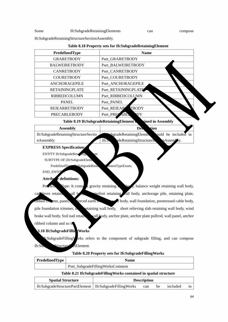
64
Some IfcSubgradeRetainingElements can compose
IfcSubgradeRetainingStructureSectionAssembly.
Table 8.18 Property sets for IfcSubgradeRetainingElement
PredefinedType Name
GRARETBODY Pset_GRARETBODY
BALWEIRETBODY Pset_BALWEIRETBODY
CANRETBODY Pset_CANRETBODY
COURETBODY Pset_COURETBODY
ANCHORAGEPILE Pset_ANCHORAGEPILE
RETAININGPLATE Pset_RETAININGPLATE
RIBBEDCOLUMN Pset_RIBBEDCOLUMN
PANEL Pset_PANEL
REIEARRETBODY Pset_REIEARRETBODY
PRECABLEBODY Pset_PRECABLEBODY
Table 8.19 IfcSubgradeRetainingElement contained in Assembly
Assembly Description
IfcSubgradeRetainingStructureSectio
nAssembly
IfcSubgradeRetainingElement should be included in
IfcSubgradeRetainingStructureSectionAssembly.
EXPRESS Specification:
ENTITY IfcSubgradeRetainingElement
SUBTYPE OF (IfcSubgradeElement);
PredefinedType: IfcSubgradeRetainingElementTypeEnum;
END_ENTITY;
Attribute definitions:
PreDefinedType: It contains gravity retaining wall body, balance weight retaining wall body,
cantilever retaining wall body, counterfort retaining wall body, anchorage pile, retaining plate,
ribbed column, panel, reinforced earth retaining wall body, wall foundation, prestressed cable body,
pile foundation trimmer, dock retaining wall body, short relieving slab retaining wall body, wind
brake wall body, Soil nail retaining wall body, anchor plate, anchor plate pullrod, wall panel, anchor
ribbed column and so on.
8.3.10 IfcSubgradeFillingWorks
IfcSubgradeFillingWorks refers to the component of subgrade filling, and can compose
IfcSubgradeStructurePartElement.
Table 8.20 Property sets for IfcSubgradeFillingWorks
PredefinedType Name
Pset_SubgradeFillingWorksCommon
Table 8.21 IfcSubgradeFillingWorks contained in spatial structure
Spatial Structure Description
IfcSubgradeStructurePartElement IfcSubgradeFillingWorks can be included in
CRBIM

65
IfcSubgradeStructurePartElement.
EXPRESS Specification:
ENTITY IfcSubgradeFillingWorks
SUBTYPE OF (IfcSubgradeElement);
PredefinedType: IfcSubgradeFillingWorksTypeEnum;
END_ENTITY;
Attribute definitions:
PreDefinedType: It contains top layer subbed, bottom layer subbed, below subbed, replace
subbed base and so on.
8.3.11 IfcSubgradeSlopeProtectionSectionElement
IfcSubgradeSlopeProtectionSectionElement refers to the basic elements of subgrade slope
protection, and can compose IfcSubgradeSlopeProtectionElement.
Table 8.22 Property sets for IfcSubgradeSlopeProtectionSectionElement
PredefinedType Name
Pset_SubgradeSlopeProtectionSectionElementCommon
Table 8.23 IfcSubgradeSlopeProtectionSectionElement contained in spatial structure
Spatial Structure Description
IfcSubgradeSlopeProtectionElement IfcSubgradeSlopeProtectionSectionElement can be
included in IfcSubgradeSlopeProtectionElement.
EXPRESS Specification:
ENTITY IfcSubgradeSlopeProtectionSectionElement
SUBTYPE OF (IfcSubgradeElement);
PredefinedType: IfcSubgradeSlopeProtectionSectionElementTypeEnum;
END_ENTITY;
Attribute definitions:
PreDefinedType: It contains arch framework, hole type protective wall, mortar rubble,
anchored frame beam, grid frame, diamond frame, human shaped frame, hollow brick, solid slope
protection, and so on.
8.3.12 IfcSubgradeSubsoilReinforcementPileElement
IfcSubgradeSubsoilReinforcementPileElement refers to the pile foundation to improve the
bearing capacity of foundation composed of soil or rock.
IfcSubgradeSubsoilReinforcementPileElement can compose
IfcSubgradeSubsoilReinforcementPileAssembly.
Table 8.24 Property sets for IfcSubgradeSubsoilReinforcementPileElement
PredefinedType Name
Pset_SubgradeSubsoilReinforcementPileElementCommon
Table 8.25 IfcSubgradeSubsoilReinforcementPileElement contained in Assembly
Assembly Description
IfcSubgradeSubsoilReinforceme IfcSubgradeSubsoilReinforcementPileElement should be
CRBIM

66
ntPileAssembly included in IfcSubgradeSubsoilReinforcementPileAssembly.
EXPRESS Specification:
ENTITY IfcSubgradeSubsoilReinforcementPileElement
SUBTYPE OF (IfcSubgradeElement);
PredefinedType: IfcSubgradeSubsoilReinforcementPileElementTypeEnum;
END_ENTITY;
Attribute definitions:
PreDefinedType: It contains pilebody and pilecap, etc.
8.3.13 IfcOriginalSubgradeSubsoilReinforcement
IfcOriginalSubgradeSubsoilReinforcement refers to the engineering measures such as
compaction, rammed, and grouting to improve the bearing capacity of foundation.
IfcOriginalSubgradeSubsoilReinforcement can compose IfcSubgradeSubsoilTreatmentElement.
Table 8.26 Property sets for IfcOriginalSubgradeSubsoilReinforcement
PredefinedType Name
Pset_OriginalSubgradeSubsoilReinforcementCommon
Table 8.27 IfcOriginalSubgradeSubsoilReinforcemen contained in spatial structure
Spatial Structure Description
IfcSubgradeSubsoilTreatmentElement IfcOriginalSubgradeSubsoilReinforcement can be
included in IfcSubgradeSubsoilTreatmentElement.
EXPRESS Specification:
ENTITY IfcOriginalSubgradeSubsoilReinforcement
SUBTYPE OF (IfcSubgradeElement);
PredefinedType: IfcOriginalSubgradeSubsoilReinforcementTypeEnum;
END_ENTITY;
Attribute definitions:
PreDefinedType: It contains compaction, rammed, grouting, sand wick, sheet drain and so on.
8.3.14 IfcSubgradeTransitionSectionElement
IfcSubgradeTransitionSectionElement refers to the basic elements of subgrade transition
section. IfcSubgradeTransitionSectionElement can compose
IfcSubgradeTransitionSectionStructureElement.
Table 8.28 Property sets for IfcSubgradeTransitionSectionElement
PredefinedType Name
TRANSITIONCONE Pset_TRANSITIONCONE
FOUNDATIONBACKFILLINGSOIL Pset_FOUNDATIONBACKFILLINGSOIL
NONSANDCONPERPLATE Pset_NONSANDCONPERPLATE
REPLACEMENTSOIL Pset_REPLACEMENTSOIL
Table 8.29 IfcSubgradeTransitionSectionElement contained in spatial structure
Spatial Structure Description
IfcSubgradeTransitionSectionStruc AIfcSubgradeTransitionSectionElement can be included
CRBIM

67
tureElement in IfcSubgradeTransitionSectionStructureElement.
EXPRESS Specification:
ENTITY IfcSubgradeTransitionSectionElement
SUBTYPE OF (IfcSubgradeElement);
PredefinedType: IfcSubgradeTransitionSectionElementTypeEnum;
END_ENTITY;
Attribute definitions:
PreDefinedType: It contains transition cone, foundation backfilling soil, non-sand concrete
permeable plate, replacement soil and so on.
8.3.15 IfcSubgradeElementAssembly
IfcSubgradeElementAssembly is the supertype of all the element assemblies in subgrade
engineering.
EXPRESS Specification:
ENTITY IfcSubgradeElementAssembly
SUPERTYPE OF (ONEOF
(IfcSubgradeRetainingStructureSectionAssembly, IfcSubgradeSubsoilReinforcementPileAssembly)
SUBTYPE OF (IfcCivilElementAssembly);
END_ENTITY;
8.3.16 IfcSubgradeRetainingStructureSectionAssembly
IfcSubgradeRetainingStructureSectionAssembly is composed of some
IfcSubgradeRetainingElement objects. Some IfcSubgradeRetainingStructureSectionAssembly
objects can compose IfcSubgradeRetainingStructureElement.
Table 8.30 IfcSubgradeRetainingStructureSectionAssembly contained in spatial structure
Spatial Structure Description
IfcSubgradeRetainingStructureElement IfcSubgradeRetainingStructureSectionAssembly
can be included in
IfcSubgradeRetainingStructureElement.
Table 8.31 IfcSubgradeRetainingStructureSectionAssembly entity composition
PredefinedType Contained Entities Description
IfcSubgradeRetainin
gElement
IfcSubgradeRetainingElement can be included in
IfcSubgradeRetainingStructureSectionAssembly.
EXPRESS Specification:
ENTITY IfcSubgradeRetainingStructureSectionAssembly
SUBTYPE OF (IfcSubgradeElementAssembly);
PredefinedType: IfcSubgradeRetainingStructureSectionAssemblyTypeEnum;
END_ENTITY;
Attribute definitions:
PreDefinedType: It contains gravity retaining wall section, balance weight retaining wall
section, cantilever retaining wall section, counterfort retaining wall section, reinforced concrete
CRBIM

68
retaining wall section, anchor bolt retaining wall section, reinforced earth retaining wall section,
prestressed cable section, pile foundation retaining wall section, dock retaining wall section, short
relieving slab retaining wall section, wind brake wall section, Soil nail retaining wall section,
anchored plate retaining wall section and so on.
8.3.17 IfcSubgradeSubsoilReinforcementPileAssembly
IfcSubgradeSubsoilReinforcementPileAssembly is composed of
IfcSubgradeTransitionSectionElement. Some IfcSubgradeSubsoilReinforcementPileAssembly
objects can compose IfcSubgradeSubsoilTreatmentElement.
Table 8.32 IfcSubgradeSubsoilReinforcementPileAssembly contained in spatial structure
Spatial Structure Description
IfcSubgradeSubsoilTreatmentElement IfcSubgradeSubsoilReinforcementPileAssembly
can be included in
IfcSubgradeSubsoilTreatmentElement.
Table 8.33 IfcSubgradeSubsoilReinforcementPileAssembly entity composition
PredefinedType Contained Entities Description
IfcSubgradeRetaining
Element
IfcSubgradeSubsoilReinforcementPileElement
can be included in
IfcSubgradeSubsoilReinforcementPileAssembly.
EXPRESS Specification:
ENTITY IfcSubgradeSubsoilReinforcementPileAssembly
SUBTYPE OF (IfcSubgradeElementAssembly);
PredefinedType: IfcSubgradeSubsoilReinforcementPileAssemblyTypeEnum;
END_ENTITY;
Attribute definitions:
PreDefinedType: It contains cement mixing pile, lime-soil compaction pile, cement fly-ash
gravel pile, chemical churning pile, column hammer expansion pile, cement soil compaction pile
and so on.
8.4 Property Set Definition
8.4.1 Pset_SubgradeStructurePartElementCommon
Name: Pset_SubgradeStructurePartElementCommon
Applicable Entities: IfcSubgradeStructurePartElement
Description: Properties common to the definition of all occurrences of
IfcSubgradeStructurePartElement.
Property Definitions: See Table 8.34.
Table 8.34 Property definitions of Pset_SubgradeStructurePartElementCommon
Name Type Description
fillingmaximum TypePropertySingleValue/IfcLengthMeasure/m Indicates the maximum
CRBIM
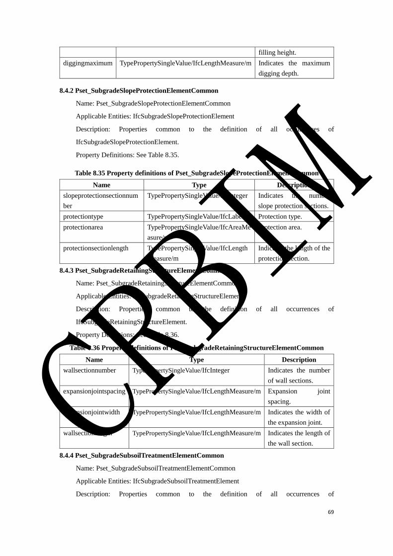
69
filling height.
diggingmaximum TypePropertySingleValue/IfcLengthMeasure/m Indicates the maximum
digging depth.
8.4.2 Pset_SubgradeSlopeProtectionElementCommon
Name: Pset_SubgradeSlopeProtectionElementCommon
Applicable Entities: IfcSubgradeSlopeProtectionElement
Description: Properties common to the definition of all occurrences of
IfcSubgradeSlopeProtectionElement.
Property Definitions: See Table 8.35.
Table 8.35 Property definitions of Pset_SubgradeSlopeProtectionElementCommon
Name Type Description
slopeprotectionsectionnum
ber
TypePropertySingleValue/IfcInteger Indicates the number
slope protection sections.
protectiontype TypePropertySingleValue/IfcLabel Protection type.
protectionarea TypePropertySingleValue/IfcAreaMe
asure/m2
Protection area.
protectionsectionlength TypePropertySingleValue/IfcLength
Measure/m
Indicates the length of the
protection section.
8.4.3 Pset_SubgradeRetainingStructureElementCommon
Name: Pset_SubgradeRetainingStructureElementCommon
Applicable Entities: IfcSubgradeRetainingStructureElement
Description: Properties common to the definition of all occurrences of
IfcSubgradeRetainingStructureElement.
Property Definitions: See Table 8.36.
Table 8.36 Property definitions of Pset_SubgradeRetainingStructureElementCommon
Name Type Description
wallsectionnumber TypePropertySingleValue/IfcInteger Indicates the number
of wall sections.
expansionjointspacing TypePropertySingleValue/IfcLengthMeasure/m Expansion joint
spacing.
expansionjointwidth TypePropertySingleValue/IfcLengthMeasure/m Indicates the width of
the expansion joint.
wallsectionlength TypePropertySingleValue/IfcLengthMeasure/m Indicates the length of
the wall section.
8.4.4 Pset_SubgradeSubsoilTreatmentElementCommon
Name: Pset_SubgradeSubsoilTreatmentElementCommon
Applicable Entities: IfcSubgradeSubsoilTreatmentElement
Description: Properties common to the definition of all occurrences of
CRBIM

70
IfcSubgradeSubsoilTreatmentElement.
Property Definitions: See Table 8.37.
Table 8.37 Property definitions of Pset_SubgradeSubsoilTreatmentElementCommon
Name Type Description
treatmentlength TypePropertySingleValue/IfcLengthMeasure/m Treatment length.
treatmentdepth TypePropertySingleValue/IfcLengthMeasure/m Treatment depth.
treatmentcapacity TypePropertySingleValue/IfcPlanarForceMeasure/Pa Capacity after
treatment.
pilenumber TypePropertySingleValue/IfcInteger Pile number.
leftboundary TypePropertySingleValue/IfcLengthMeasure/m Left boundary.
rightboundary TypePropertySingleValue/IfcLengthMeasure/m Right boundary.
8.4.5 Pset_REICONRETWALL
Name: Pset_REICONRETWALL
Applicable Entities: IfcSubgradeRetainingStructure/REICONRETWALL
Description: A set of properties of reinforced concrete retaining walls.
Property Definitions: See Table 8.38.
Table 8.38 Property definitions of Pset_REICONRETWALL
Name Type Description
anchorpilesnumber TypePropertySingleValue/IfcInteger The number of anchor piles.
retainingplatenumber TypePropertySingleValue/IfcInteger The number of retaining plates.
8.4.6 Pset_ANCBOLTRETWALL
Name: Pset_ANCBOLTRETWALL
Applicable Entities: IfcSubgradeRetainingStructure/ANCBOLTRETWALL
Description: A set of properties of anchor bolt retaining walls.
Property Definitions: See Table 8.39.
Table 8.39 Property definitions of Pset_ANCBOLTRETWALL
Name Type Description
ribbedcolumnnumber TypePropertySingleValue/IfcInteger Ribbed column number.
panelnumber TypePropertySingleValue/IfcInteger Panel number.
anchoredboltnumber TypePropertySingleValue/IfcInteger Anchored bolt number.
8.4.7 Pset_EMBANKMENTCUTTING
Name: Pset_EMBANKMENTCUTTING
Applicable Entities: IfcSubgradeTransitionSectionStructure/EMBANKMENTCUTTING
Description: A set of properties of embankment and cutting.
Property Definitions: See Table 8.40.
Table 8.40 Property definitions of Pset_EMBANKMENTCUTTING
Name Type Description
CRBIM
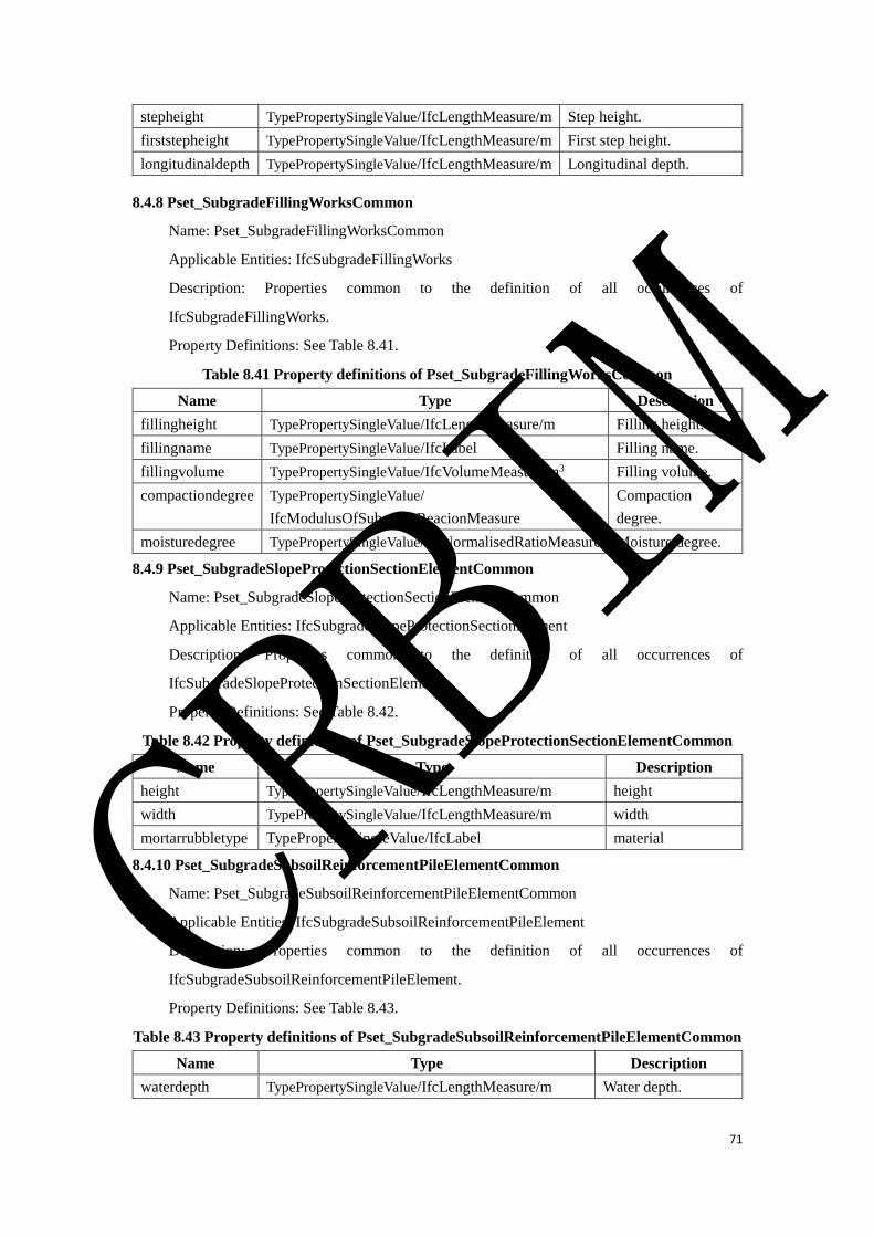
71
stepheight TypePropertySingleValue/IfcLengthMeasure/m Step height.
firststepheight TypePropertySingleValue/IfcLengthMeasure/m First step height.
longitudinaldepth TypePropertySingleValue/IfcLengthMeasure/m Longitudinal depth.
8.4.8 Pset_SubgradeFillingWorksCommon
Name: Pset_SubgradeFillingWorksCommon
Applicable Entities: IfcSubgradeFillingWorks
Description: Properties common to the definition of all occurrences of
IfcSubgradeFillingWorks.
Property Definitions: See Table 8.41.
Table 8.41 Property definitions of Pset_SubgradeFillingWorksCommon
Name Type Description
fillingheight TypePropertySingleValue/IfcLengthMeasure/m Filling height.
fillingname TypePropertySingleValue/IfcLabel Filling name.
fillingvolume TypePropertySingleValue/IfcVolumeMeasure/m3 Filling volume.
compactiondegree TypePropertySingleValue/
IfcModulusOfSubgradeReacionMeasure
Compaction
degree.
moisturedegree TypePropertySingleValue/IfcNormalisedRatioMeasure Moisture degree.
8.4.9 Pset_SubgradeSlopeProtectionSectionElementCommon
Name: Pset_SubgradeSlopeProtectionSectionElementCommon
Applicable Entities: IfcSubgradeSlopeProtectionSectionElement
Description: Properties common to the definition of all occurrences of
IfcSubgradeSlopeProtectionSectionElement.
Property Definitions: See Table 8.42.
Table 8.42 Property definitions of Pset_SubgradeSlopeProtectionSectionElementCommon
Name Type Description
height TypePropertySingleValue/IfcLengthMeasure/m height
width TypePropertySingleValue/IfcLengthMeasure/m width
mortarrubbletype TypePropertySingleValue/IfcLabel material
8.4.10 Pset_SubgradeSubsoilReinforcementPileElementCommon
Name: Pset_SubgradeSubsoilReinforcementPileElementCommon
Applicable Entities: IfcSubgradeSubsoilReinforcementPileElement
Description: Properties common to the definition of all occurrences of
IfcSubgradeSubsoilReinforcementPileElement.
Property Definitions: See Table 8.43.
Table 8.43 Property definitions of Pset_SubgradeSubsoilReinforcementPileElementCommon
Name Type Description
waterdepth TypePropertySingleValue/IfcLengthMeasure/m Water depth.
CRBIM
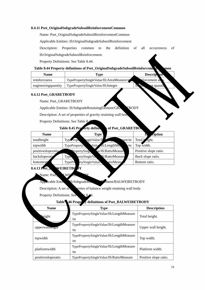
72
8.4.11 Pset_OriginalSubgradeSubsoilReinforcementCommon
Name: Pset_OriginalSubgradeSubsoilReinforcementCommon
Applicable Entities: IfcOriginalSubgradeSubsoilReinforcement
Description: Properties common to the definition of all occurrences of
IfcOriginalSubgradeSubsoilReinforcement.
Property Definitions: See Table 8.44.
Table 8.44 Property definitions of Pset_OriginalSubgradeSubsoilReinforcementCommon
Name Type Description
reinforcearea TypePropertySingleValue/IfcAreaMeasure/m2 Reinforcement area.
engineeringquantity TypePropertySingleValue/IfcInteger Engineering quantity.
8.4.12 Pset_GRARETBODY
Name: Pset_GRARETBODY
Applicable Entities: IfcSubgradeRetainingElement/GRARETBODY
Description: A set of properties of gravity retaining wall body.
Property Definitions: See Table 8.45.
Table 8.45 Property definitions of Pset_GRARETBODY
Name Type Description
totalheight TypePropertySingleValue/IfcLengthMeasure/m Total height.
topwidth TypePropertySingleValue/IfcLengthMeasure/m Top width.
positivesloperatio TypePropertySingleValue/IfcRatioMeasure Positive slope ratio.
backsloperatio TypePropertySingleValue/IfcRatioMeasure Back slope ratio.
bottomratio TypePropertySingleValue/IfcRatioMeasure Bottom ratio.
8.4.13 Pset_BALWEIRETBODY
Name: Pset_BALWEIRETBODY
Applicable Entities: IfcSubgradeRetainingElement/BALWEIRETBODY
Description: A set of properties of balance weight retaining wall body.
Property Definitions: See Table 8.46.
Table 8.46 Property definitions of Pset_BALWEIRETBODY
Name Type Description
totalheight TypePropertySingleValue/IfcLengthMeasure
/m Total height.
upperwallheight TypePropertySingleValue/IfcLengthMeasure
/m Upper wall height.
topwidth TypePropertySingleValue/IfcLengthMeasure
/m Top width.
platformwidth TypePropertySingleValue/IfcLengthMeasure
/m Platform width.
positivesloperatio TypePropertySingleValue/IfcRatioMeasure Positive slope ratio.
CRBIM
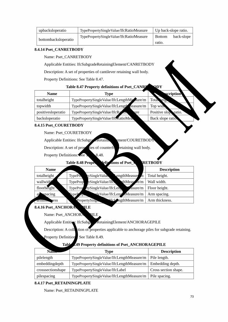
73
upbacksloperatio TypePropertySingleValue/IfcRatioMeasure Up back-slope ratio.
bottombacksloperatio TypePropertySingleValue/IfcRatioMeasure Bottom back-slope
ratio.
8.4.14 Pset_CANRETBODY
Name: Pset_CANRETBODY
Applicable Entities: IfcSubgradeRetainingElement/CANRETBODY
Description: A set of properties of cantilever retaining wall body.
Property Definitions: See Table 8.47.
Table 8.47 Property definitions of Pset_CANRETBODY
Name Type Description
totalheight TypePropertySingleValue/IfcLengthMeasure/m Total height.
topwidth TypePropertySingleValue/IfcLengthMeasure/m Top width.
positivesloperatio TypePropertySingleValue/IfcRatioMeasure Positive slope ratio.
backsloperatio TypePropertySingleValue/IfcRatioMeasure Back slope ratio.
8.4.15 Pset_COURETBODY
Name: Pset_COURETBODY
Applicable Entities: IfcSubgradeRetainingElement/COURETBODY
Description: A set of properties of counterfort retaining wall body.
Property Definitions: See Table 8.48.
Table 8.48 Property definitions of Pset_COURETBODY
Name Type Description
totalheight TypePropertySingleValue/IfcLengthMeasure/m Total height.
wallwidth TypePropertySingleValue/IfcLengthMeasure/m Wall width.
floorheight TypePropertySingleValue/IfcLengthMeasure/m Floor height.
armspacing TypePropertySingleValue/IfcLengthMeasure/m Arm spacing.
armthickness TypePropertySingleValue/IfcLengthMeasure/m Arm thickness.
8.4.16 Pset_ANCHORAGEPILE
Name: Pset_ANCHORAGEPILE
Applicable Entities: IfcSubgradeRetainingElement/ANCHORAGEPILE
Description: A collection of properties applicable to anchorage piles for subgrade retaining.
Property Definitions: See Table 8.49.
Table 8.49 Property definitions of Pset_ANCHORAGEPILE
Name Type Description
pilelength TypePropertySingleValue/IfcLengthMeasure/m Pile length.
embeddingdepth TypePropertySingleValue/IfcLengthMeasure/m Embedding depth.
crosssectionshape TypePropertySingleValue/IfcLabel Cross section shape.
pilespacing TypePropertySingleValue/IfcLengthMeasure/m Pile spacing.
8.4.17 Pset_RETAININGPLATE
Name: Pset_RETAININGPLATE
CRBIM

74
Applicable Entities: IfcSubgradeRetainingElement/RETAININGPLATE
Description: A collection of properties applicable to retaining plates for subgrade retaining.
Property Definitions: See Table 8.50.
Table 8.50 Property definitions of Pset_RETAININGPLATE
Name Type Description
platethickness TypePropertySingleValue/IfcLengthMeasure/m Plate thickness.
platewidth TypePropertySingleValue/IfcLengthMeasure/m Plate width.
8.4.18 Pset_RIBBEDCOLUMN
Name: Pset_RIBBEDCOLUMN
Applicable Entities: IfcSubgradeRetainingElement/RIBBEDCOLUMN
Description: A collection of properties applicable to ribbed columns for subgrade retaining.
Property Definitions: See Table 8.51.
Table 8.51 Property definitions of Pset_RIBBEDCOLUMN
Name Type Description
totalheight TypePropertySingleValue/IfcLengthMeas
ure/m
Total height of the
wall.
wallbottomsupportcondition TypePropertySingleValue/IfcLabel Wall bottom
support condition.
8.4.19 Pset_PANEL
Name: Pset_PANEL
Applicable Entities: IfcSubgradeRetainingElement/PANEL
Description: A collection of properties applicable to panels for subgrade retaining.
Property Definitions: See Table 8.52.
Table 8.52 Property definitions of Pset_PANEL
Name Type Description
retainingplatewidth TypePropertySingleValue/IfcLengthMeasure/m Indicates the width of
the retaining plate.
retainingplatethickness
TypePropertySingleValue/IfcLengthMeasure/m Indicates the
thickness of the
retaining plate.
8.4.20 Pset_REIEARRETBODY
Name: Pset_REIEARRETBODY
Applicable Entities: IfcSubgradeRetainingElement/REIEARRETBODY
Description: A collection of properties applicable to reinforced earth retaining wall body.
Property Definitions: See Table 8.53.
Table 8.53 Property definitions of Pset_REIEARRETBODY
Name Type Description
totalheight TypePropertySingleValue/IfcLengthMeasure/m Total height of the wall.
CRBIM
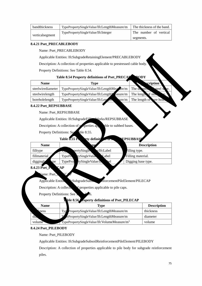
75
bandthickness TypePropertySingleValue/IfcLengthMeasure/m The thickness of the band.
verticalsegment TypePropertySingleValue/IfcInteger The number of vertical
segments.
8.4.21 Pset_PRECABLEBODY
Name: Pset_PRECABLEBODY
Applicable Entities: IfcSubgradeRetainingElement/PRECABLEBODY
Description: A collection of properties applicable to prestressed cable body.
Property Definitions: See Table 8.54.
Table 8.54 Property definitions of Pset_PRECABLEBODY
Name Type Description
steelwirediameter TypePropertySingleValue/IfcLengthMeasure/m The diameter of steel wire.
steelwirelength TypePropertySingleValue/IfcLengthMeasure/m The length of steel wire.
boreholelength TypePropertySingleValue/IfcLengthMeasure/m The length of bore hole.
8.4.22 Pset_REPSUBBASE
Name: Pset_REPSUBBASE
Applicable Entities: IfcSubgradeFillingWorks/REPSUBBASE
Description: A collection of properties applicable to subbed bases.
Property Definitions: See Table 8.55.
Table 8.55 Property definitions of Pset_REPSUBBASE
Name Type Description
filltype TypePropertySingleValue/IfcLabel Filling type.
fillmaterial TypePropertySingleValue/ IfcLabel Filling material.
diggingbasetype TypePropertySingleValue/IfcLabel Digging base type.
8.4.23 Pset_PILECAP
Name: Pset_PILECAP
Applicable Entities: IfcSubgradeSubsoilReinforcementPileElement/PILECAP
Description: A collection of properties applicable to pile caps.
Property Definitions: See Table 8.56.
Table 8.56 Property definitions of Pset_PILECAP
Name Type Description
thickness TypePropertySingleValue/IfcLengthMeasure/m thickness
diameter TypePropertySingleValue/IfcLengthMeasure/m diameter
volume TypePropertySingleValue/IfcVolumeMeasure/m3 volume
8.4.24 Pset_PILEBODY
Name: Pset_PILEBODY
Applicable Entities: IfcSubgradeSubsoilReinforcementPileElement/PILEBODY
Description: A collection of properties applicable to pile body for subgrade reinforcement
piles.
CRBIM
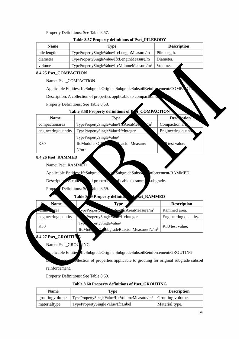
76
Property Definitions: See Table 8.57.
Table 8.57 Property definitions of Pset_PILEBODY
Name Type Description
pile length TypePropertySingleValue/IfcLengthMeasure/m Pile length.
diameter TypePropertySingleValue/IfcLengthMeasure/m Diameter.
volume TypePropertySingleValue/IfcVolumeMeasure/m3 Volume.
8.4.25 Pset_COMPACTION
Name: Pset_COMPACTION
Applicable Entities: IfcSubgradeOriginalSubgradeSubsoilReinforcement/COMPACTION
Description: A collection of properties applicable to compaction subgrade.
Property Definitions: See Table 8.58.
Table 8.58 Property definitions of Pset_COMPACTION
Name Type Description
compactionarea TypePropertySingleValue/IfcAreaMeasure/m2 Compaction area.
engineeringquantity TypePropertySingleValue/IfcInteger Engineering quantity.
K30
TypePropertySingleValue/
IfcModulusOfSubgradeReacionMeasure/
N/m3
K30 test value.
8.4.26 Pset_RAMMED
Name: Pset_RAMMED
Applicable Entities: IfcSubgradeOriginalSubgradeSubsoilReinforcement/RAMMED
Description: A collection of properties applicable to rammed subgrade.
Property Definitions: See Table 8.59.
Table 8.59 Property definitions of Pset_RAMMED
Name Type Description
rammedarea TypePropertySingleValue/IfcAreaMeasure/m2 Rammed area.
engineeringquantity TypePropertySingleValue/IfcInteger Engineering quantity.
K30 TypePropertySingleValue/
IfcModulusOfSubgradeReacionMeasure/ N/m3 K30 test value.
8.4.27 Pset_GROUTING
Name: Pset_GROUTING
Applicable Entities: IfcSubgradeOriginalSubgradeSubsoilReinforcement/GROUTING
Description: A collection of properties applicable to grouting for original subgrade subsoil
reinforcement.
Property Definitions: See Table 8.60.
Table 8.60 Property definitions of Pset_GROUTING
Name Type Description
groutingvolume TypePropertySingleValue/IfcVolumeMeasure/m3 Grouting volume.
materialtype TypePropertySingleValue/IfcLabel Material type.
CRBIM
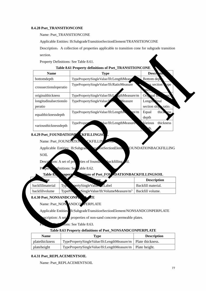
77
8.4.28 Pset_TRANSITIONCONE
Name: Pset_TRANSITIONCONE
Applicable Entities: IfcSubgradeTransitionSectionElement/TRANSITIONCONE
Description:A collection of properties applicable to transition cone for subgrade transition
section.
Property Definitions: See Table 8.61.
Table 8.61 Property definitions of Pset_TRANSITIONCONE
Name Type Description
bottomdepth TypePropertySingleValue/IfcLengthMeasure/m Bottom depth.
crosssectionsloperatio TypePropertySingleValue/IfcRatioMeasure Cross section slope
ratio.
originalthickness TypePropertySingleValue/IfcLengthMeasure/m Original thickness.
longitudinalsectionslo
peratio
TypePropertySingleValue/IfcRatioMeasure Longitudinal
section slope ratio.
equalthicknessdepth TypePropertySingleValue/IfcLengthMeasure/m Equal thickness
depth
variousthicknessdepth TypePropertySingleValue/IfcLengthMeasure/m Various thickness
depth.
8.4.29 Pset_FOUNDATIONBACKFILLINGSOIL
Name: Pset_FOUNDATIONBACKFILLINGSOIL
Applicable Entities: IfcSubgradeTransitionSectionElement/FOUNDATIONBACKFILLING
SOIL
Description: A set of properties of foundation backfilling soil.
Property Definitions: See Table 8.62.
Table 8.62 Property definitions of Pset_FOUNDATIONBACKFILLINGSOIL
Name Type Description
backfillmaterial TypePropertySingleValue/IfcLabel Backfill material.
backfillvolume TypePropertySingleValue/IfcVolumeMeasure/m3 Backfill volume.
8.4.30 Pset_NONSANDCONPERPLATE
Name: Pset_NONSANDCONPERPLATE
Applicable Entities: IfcSubgradeTransitionSectionElement/NONSANDCONPERPLATE
Description: A set of properties of non-sand concrete permeable plates.
Property Definitions: See Table 8.63.
Table 8.63 Property definitions of Pset_NONSANDCONPERPLATE
Name Type Description
platethickness TypePropertySingleValue/IfcLengthMeasure/m Plate thickness.
plateheight TypePropertySingleValue/IfcLengthMeasure/m Plate height.
8.4.31 Pset_REPLACEMENTSOIL
Name: Pset_REPLACEMENTSOIL
CRBIM

78
Applicable Entities: IfcSubgradeTransitionSectionElement/REPLACEMENTSOIL
Description: A set of properties of replacement soil.
Property Definitions: See Table 8.64.
Table 8.64 Property definitions of Pset_REPLACEMENTSOIL
Name Type Description
fillthickness TypePropertySingleValue/IfcLengthMeasure/m Filling thickness.
fillmaterial TypePropertySingleValue/IfcLabel Filling material.
9.Bridge Schema
9.1 Schema Definition
The information model defined in this schema includes beam bridge, arch bridge, rigid frame
bridge, cable-stayed bridge, suspension bridge, frame bridge, culvert and their main components.
The basic data architecture of bridge information model is composed of
IfcBridgeStructureElement, IfcBridgeElementAssembly and IfcBridgeElement.
IfcBridgeStructureElement includes IfcBridge and IfcBridgePart.
IfcBridgeElementAssembly includes IfcBridgeTruss, IfcBridgeJoint,
IfcBeamFallingPreventionDevice and IfcCrossBrace.
IfcBridgeElement includes IfcBridgeMember, IfcStiffeningRib, IfcBridgeSlab,
IfcBridgeGirderSegment, IfcBridgeGearBlocks, IfcBridgeBedstone, IfcBridgePierSegment,
IfcBridgeAbutmentSegment, IfcBridgePylon, IfcBridgeArchrib, IfcBridgeArchfoot,
IfcBridgeStandColumn, IfcBridgeSuspender, IfcBridgeCable, IfcBridgeSuspendedTendon,
IfcBridgeBearing, IfcBridgeExpansionInstallation, IfcBridgeProtectingWall,
IfcBridgeFrameSegment, IfcBridgeWingWall, IfcBridgeCulvertSegment, IfcBridgeHatStone,
IfcBridgeCoping, IfcBridgeEmbeddedPartsFoundation and IfcBridgeRefugePlatform.
The relationship between all the classes in the bridge domain is shown in Figure 9.1.
CRBIM
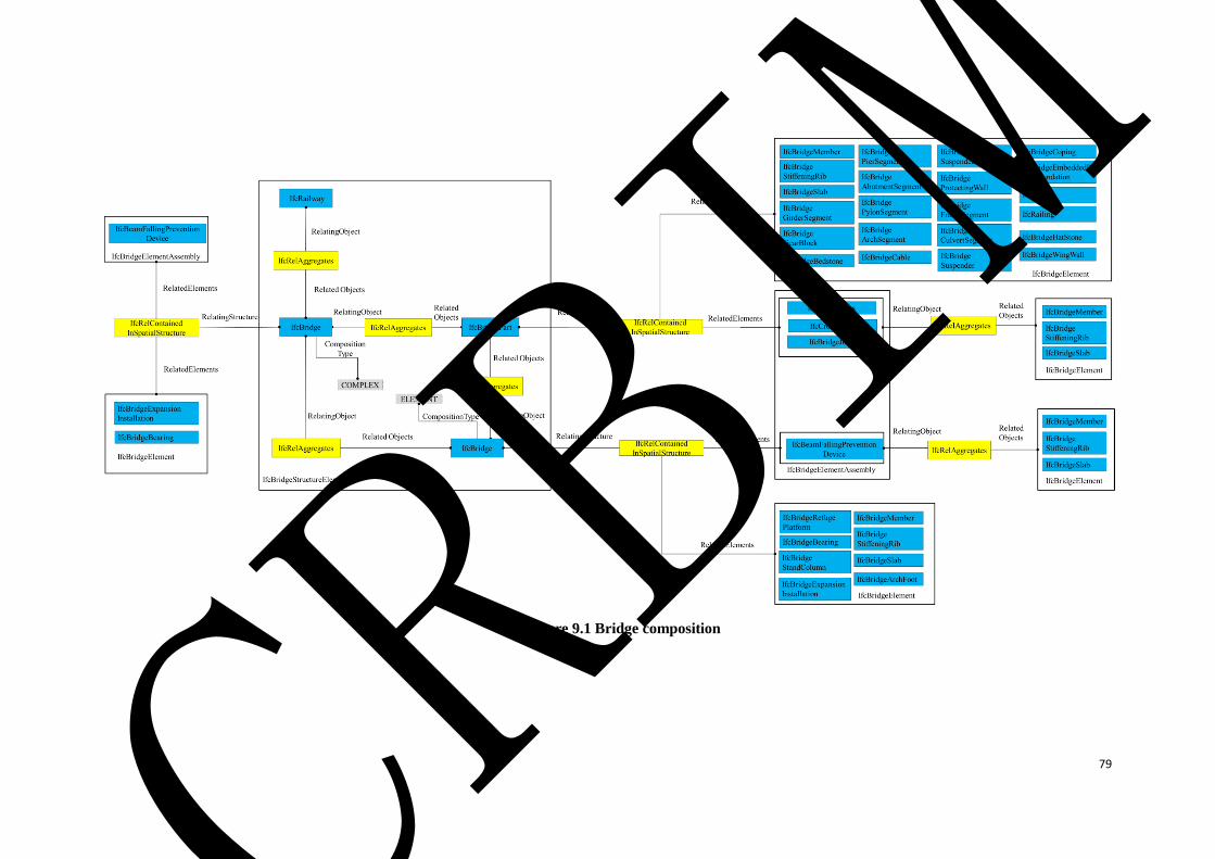
79
Figure 9.1 Bridge composition
CRBIM
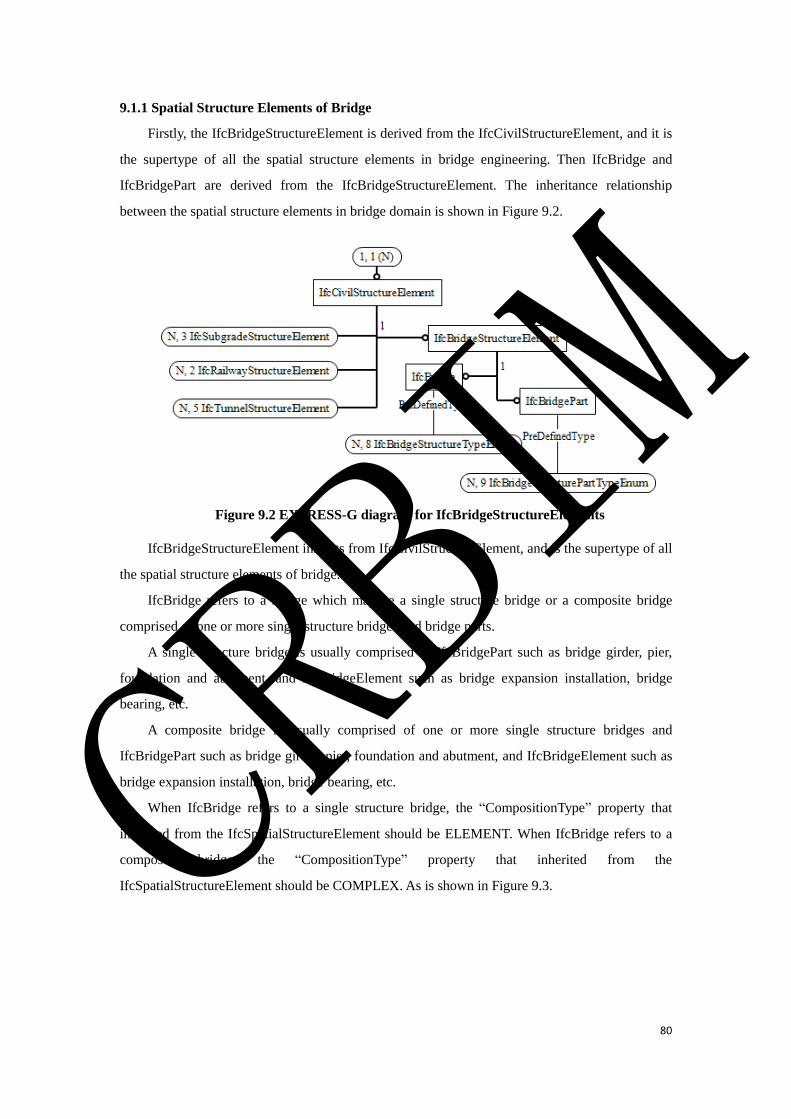
80
9.1.1 Spatial Structure Elements of Bridge
Firstly, the IfcBridgeStructureElement is derived from the IfcCivilStructureElement, and it is
the supertype of all the spatial structure elements in bridge engineering. Then IfcBridge and
IfcBridgePart are derived from the IfcBridgeStructureElement. The inheritance relationship
between the spatial structure elements in bridge domain is shown in Figure 9.2.
Figure 9.2 EXPRESS-G diagram for IfcBridgeStructureElements
IfcBridgeStructureElement inherits from IfcCivilStructureElement, and is the supertype of all
the spatial structure elements of bridge.
IfcBridge refers to a bridge which may be a single structure bridge or a composite bridge
comprised of one or more single structure bridges and bridge parts.
A single structure bridge is usually comprised of IfcBridgePart such as bridge girder, pier,
foundation and abutment, and IfcBridgeElement such as bridge expansion installation, bridge
bearing, etc.
A composite bridge is usually comprised of one or more single structure bridges and
IfcBridgePart such as bridge girder, pier, foundation and abutment, and IfcBridgeElement such as
bridge expansion installation, bridge bearing, etc.
When IfcBridge refers to a single structure bridge, the “CompositionType” property that
inherited from the IfcSpatialStructureElement should be ELEMENT. When IfcBridge refers to a
composite bridge, the “CompositionType” property that inherited from the
IfcSpatialStructureElement should be COMPLEX. As is shown in Figure 9.3. CRBIM
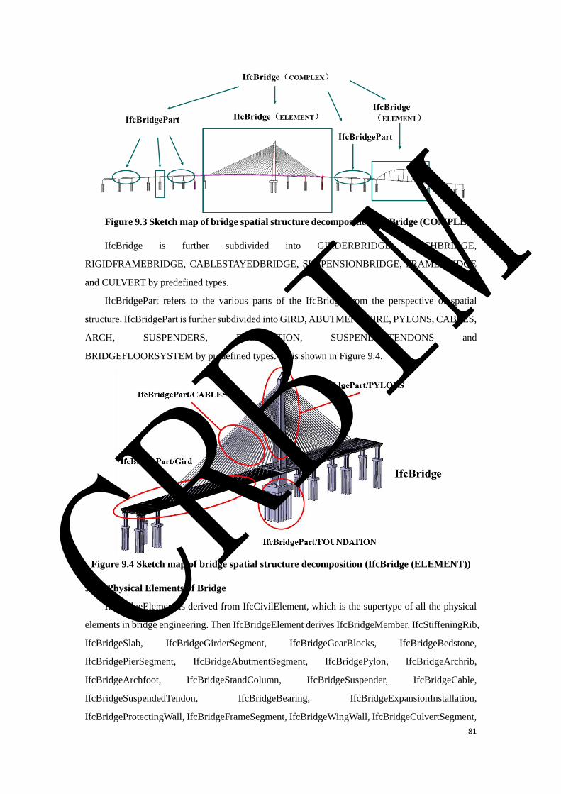
81
Figure 9.3 Sketch map of bridge spatial structure decomposition (IfcBridge (COMPLEX))
IfcBridge is further subdivided into GIRDERBRIDGE, ARCHBRIDGE,
RIGIDFRAMEBRIDGE, CABLESTAYEDBRIDGE, SUSPENSIONBRIDGE, FRAMEBRIDGE
and CULVERT by predefined types.
IfcBridgePart refers to the various parts of the IfcBridge from the perspective of spatial
structure. IfcBridgePart is further subdivided into GIRD, ABUTMENT, PIRE, PYLONS, CABLES,
ARCH, SUSPENDERS, FOUNDATION, SUSPENDEDTENDONS and
BRIDGEFLOORSYSTEM by predefined types. As is shown in Figure 9.4.
Figure 9.4 Sketch map of bridge spatial structure decomposition (IfcBridge (ELEMENT))
9.1.2 Physical Elements of Bridge
IfcBridgeElement is derived from IfcCivilElement, which is the supertype of all the physical
elements in bridge engineering. Then IfcBridgeElement derives IfcBridgeMember, IfcStiffeningRib,
IfcBridgeSlab, IfcBridgeGirderSegment, IfcBridgeGearBlocks, IfcBridgeBedstone,
IfcBridgePierSegment, IfcBridgeAbutmentSegment, IfcBridgePylon, IfcBridgeArchrib,
IfcBridgeArchfoot, IfcBridgeStandColumn, IfcBridgeSuspender, IfcBridgeCable,
IfcBridgeSuspendedTendon, IfcBridgeBearing, IfcBridgeExpansionInstallation,
IfcBridgeProtectingWall, IfcBridgeFrameSegment, IfcBridgeWingWall, IfcBridgeCulvertSegment,
CRBIM
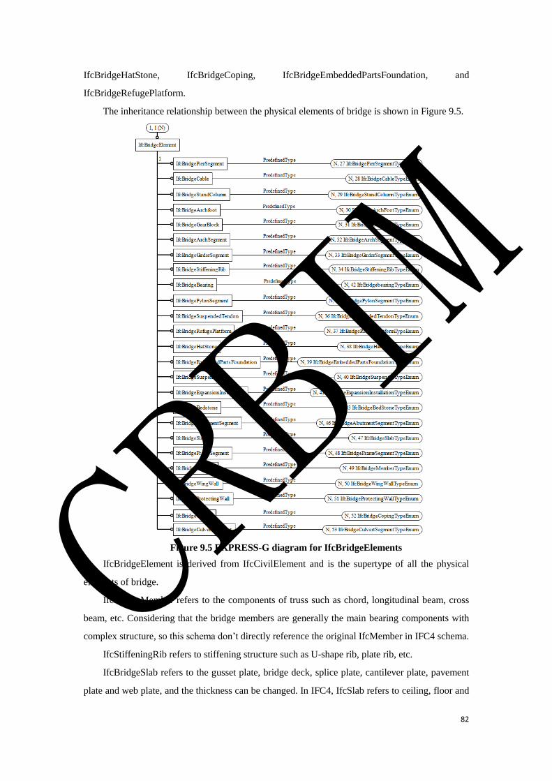
82
IfcBridgeHatStone, IfcBridgeCoping, IfcBridgeEmbeddedPartsFoundation, and
IfcBridgeRefugePlatform.
The inheritance relationship between the physical elements of bridge is shown in Figure 9.5.
Figure 9.5 EXPRESS-G diagram for IfcBridgeElements
IfcBridgeElement is derived from IfcCivilElement and is the supertype of all the physical
elements of bridge.
IfcBridgeMember refers to the components of truss such as chord, longitudinal beam, cross
beam, etc. Considering that the bridge members are generally the main bearing components with
complex structure, so this schema don’t directly reference the original IfcMember in IFC4 schema.
IfcStiffeningRib refers to stiffening structure such as U-shape rib, plate rib, etc.
IfcBridgeSlab refers to the gusset plate, bridge deck, splice plate, cantilever plate, pavement
plate and web plate, and the thickness can be changed. In IFC4, IfcSlab refers to ceiling, floor and
CRBIM

83
stair board in the building, and IfcPlate mainly refers to the flat plate with a uniform thickness.
IfcSlab and IfcPlate can’t fully meet the requirements for the bridge slabs, therefore this schema
don’t directly use IfcSlab or IfcPlate to define the bridge slabs.
IfcBridgeGirderSegment refers to the segment of the main girder of the bridge. Because the
main girder is constructed segment by segment and the section size of the main girder is different at
different locations, so the main girder is not defined as a physical element.
IfcBridgeGearBlocks refers to the wedge structure of anchorage prestressed steel strand. The
gear block is generally designed separately, so it is defined as an entity.
IfcBridgeBedstone refers to the structure placed on the top of the pier or abutment to support
the bearing.
IfcBridgePierSegment refers to the pier shaft segment, the top cap or the tray. Because the
bridge pier is poured segment by segment in the construction process and the materials of the pier,
the top cap and the tray are different, so the bridge pier is not defined as a physical element.
IfcBridgeAbutmentSegment refers to the components of the abutment. Because the bridge
abutment is poured segment by segment in the construction process, so the bridge abutment is not
defined as a physical element.
IfcBridgePylonsegment refers to the components of the pylon. Because the bridge pylon is
poured or assembled segment by segment in the construction process, so the bridge pylon is not
defined as a physical element.
IfcBridgeArchrib refers to the components of the arch. Because the bridge arch is poured or
assembled segment by segment in the construction process, so the bridge arch is not defined as a
physical element.
IfcBridgeArchfoot refers to the structure used to support the arch rib and connect the
foundation or main girder to the arch rib.
IfcBridgeStandColumn refers to the structure on the arch rib to support the main girder.
IfcBridgeSuspender refers to the structure used to connect the suspension cable or the arch rib
with the bridge floor system. A bridge suspender comprises a hanger body, sheath, sleeve, bolts, etc.
IfcBridgeCable refers to the structure used to connect the pylon with the bridge floor system.
A bridge cable comprises a hanger body, sheath, sleeve, bolts, etc.
IfcBridgeSuspendedTendon refers to the single suspension cable, which comprises steel wire,
sheath, etc.
IfcBridgeBearing refers to the structure used to support the main girder and transfer the load
from the superstructure to the bridge pier.
IfcBridgeExpansionInstallation refers to the structure installed on between two main girders to
facilitate the vehicle smoothly pass the bridge deck and to meet the deformation of the upper
CRBIM

84
structure of the bridge. It is comprised of rubber and steel parts.
IfcBridgeProtectingWall refers to the structure located on the bridge deck to protect the
pedestrians and to retain the ballast. The IfcWall defined in IFC4 mainly refers to the wall of the
building. In order to emphasize the specific meaning of the bridge protection wall, IfcWall is not
used.
IfcBridgeFrameSegment refers to a segment of a frame bridge. Because the main body of the
frame bridge is casted or assembled segment by segment in the construction process, so the frame
bridge is not defined as a physical element.
IfcBridgeWingWall refers to the structure at the inlet and outlet of a culvert or a frame bridge to
ensure the two sides of the embankment slope stability and to guide the river. The IfcWall defined
in IFC4 mainly refers to the wall of the building. To emphasize the specific meaning of the bridge
wing wall, IfcWall is not used.
IfcBridgeCulvertSegment refers to a segment of a culvert. Because the culvert body is usually
designed and constructed segment by segment in the design and construction process, so the culvert
is not defined as a physical element.
IfcBridgeHatStone refers to the structure located on the end of the wing wall of the culvert to
support the subgrade filling material.
IfcBridgeCoping refers to the structure set on the top of the frame or the double column pier to
support, distribute and transfer the load of the upper structure, also known as cap beam.
IfcBridgeEmbeddedPartsFoundation refers to the joint structure placed on bridge deck or piers
to connect other structures.
IfcBridgeRefugePlatform refers to the platform on the bridge for maintenance personnel to
avoid the train.
9.1.3 Element Assemblies of Bridge
IfcBridgeElementAssembly is derived from the IfcCivilElementAssembly and is the supertype
of all the element assemblies in bridge engineering. Then IfcBridgeElementAssembly derives
IfcBridgeTruss, IfcBridgeJoint, IfcBeamFallingPreventionDevice and IfcCrossBrace. The
inheritance relationship between the element assemblies of the bridge is shown in Figure 9.6. CRBIM
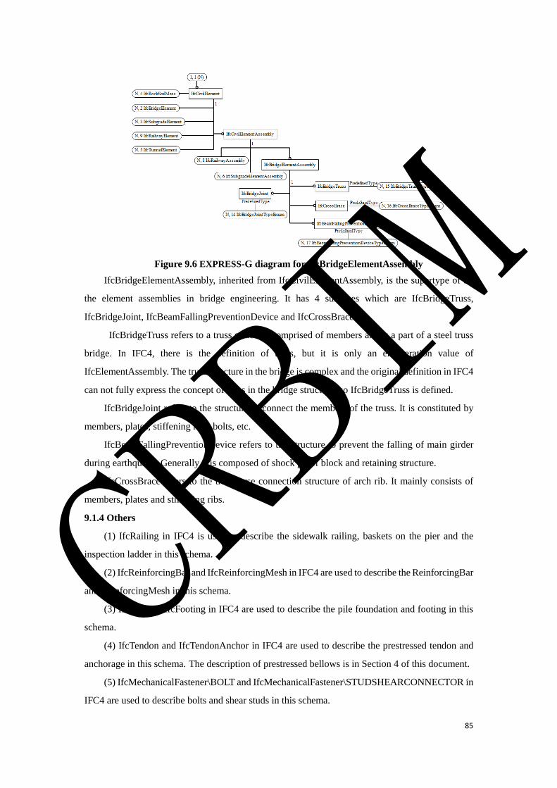
85
Figure 9.6 EXPRESS-G diagram for IfcBridgeElementAssembly
IfcBridgeElementAssembly, inherited from IfcCivilElementAssembly, is the supertype of all
the element assemblies in bridge engineering. It has 4 subtypes which are IfcBridgeTruss,
IfcBridgeJoint, IfcBeamFallingPreventionDevice and IfcCrossBrace.
IfcBridgeTruss refers to a truss structure comprised of members and is a part of a steel truss
bridge. In IFC4, there is the definition of truss, but it is only an enumeration value of
IfcElementAssembly. The truss structure in the bridge is complex and the original definition in IFC4
can not fully express the concept of truss in the bridge structure, so IfcBridgeTruss is defined.
IfcBridgeJoint refers to the structure to connect the members of the truss. It is constituted by
members, plates, stiffening ribs, bolts, etc.
IfcBeamFallingPreventionDevice refers to the structure to prevent the falling of main girder
during earthquake. Generally it is composed of shock proof block and retaining structure.
IfcCrossBrace refers to the transverse connection structure of arch rib. It mainly consists of
members, plates and stiffening ribs.
9.1.4 Others
(1) IfcRailing in IFC4 is used to describe the sidewalk railing, baskets on the pier and the
inspection ladder in this schema.
(2) IfcReinforcingBar and IfcReinforcingMesh in IFC4 are used to describe the ReinforcingBar
and ReinforcingMesh in this schema.
(3) IfcPile and IfcFooting in IFC4 are used to describe the pile foundation and footing in this
schema.
(4) IfcTendon and IfcTendonAnchor in IFC4 are used to describe the prestressed tendon and
anchorage in this schema. The description of prestressed bellows is in Section 4 of this document.
(5) IfcMechanicalFastener\BOLT and IfcMechanicalFastener\STUDSHEARCONNECTOR in
IFC4 are used to describe bolts and shear studs in this schema.
CRBIM
86
(6) IfcFastener\WELD in IFC4 is used to describe the weld in this schema.
(7) IfcDiscreteAccessory\ANCHORPLATE in IFC4 is used to describe the anchor plate in this
schema.
(8) The definition of cable slot is in Section 14 of this document.
(9) The definition of drainage pipe, chute and flow well is in Section 11 of this document.
9.2 Type Definition
9.2.1 IfcBridgeStructureTypeEnum
IfcBridgeStructureTypeEnum is an enumeration of bridge structure types, to define the
different types of bridges from the perspective of the bridge’s structural style.
Enumerated Item Definitions:
GIRDERBRIDGE;
ARCHBRIDGE;
RIGIDFRAMEBRIDGE;
CABLESTAYEDBRIDGE;
SUSPENSIONBRIDGE;
FRAME BRIDGE;
CULVERT;
USERDEFINED;
NOTDEFINED.
EXPRESS Specification:
TYPE IfcBridgeStructureTypeEnum = ENUMERATION OF
(GIRDERBRIDGE
,ARCHBRIDGE
,RIGIDFRAMEBRIDGE
,CABLESTAYEDBRIDGE
,SUSPENSIONBRIDGE
,FRAME BRIDGE
,CULVERT
,USERDEFINED
,NOTDEFINED);
END_TYPE;
9.2.2 IfcBridgeStructurePartTypeEnum
IfcBridgeStructurePartTypeEnum defines the different types of bridge structure parts.
Enumerated Item Definitions:
GIRD;
ABUTMENT;
PIRE;
CRBIM

87
PYLONS;
CABLES;
ARCH;
SUSPENDERS;
FOUNDATION;
SUSPENDEDTENDONS;
BRIDGEFLOORSYSTEM;
USERDEFINED;
NOTDEFINED.
EXPRESS Specification:
TYPE IfcBridgeStructurePartTypeEnum = ENUMERATION OF
(GIRD
,ABUTMENT
,PIRE
,PYLONS
,CABLES
,ARCH
,SUSPENDERS
,FOUNDATION
,SUSPENDEDTENDONS
,BRIDGEFLOORSYSTEM
,USERDEFINED
,NOTDEFINED);
END_TYPE;
9.2.3 IfcBridgeMemberTypeEnum
IfcBridgeMemberTypeEnum defines the different types of bridge members.
Enumerated Item Definitions:
USERDEFINED;
NOTDEFINED.
EXPRESS Specification:
TYPE IfcBridgeMemberTypeEnum = ENUMERATION OF
(USERDEFINED
,NOTDEFINED);
END_TYPE;
9.2.4 IfcBridgeStiffeningRibTypeEnum
IfcBridgeStiffeningRibTypeEnum defines the different types of bridge stiffening ribs.
Enumerated Item Definitions:
CRBIM
88
USERDEFINED;
NOTDEFINED.
EXPRESS Specification:
TYPE IfcBridgeStiffeningRibTypeEnum = ENUMERATION OF
(USERDEFINED
,NOTDEFINED);
END_TYPE;
9.2.5 IfcBridgeSlabTypeEnum
IfcBridgeSlabTypeEnum defines the different types of bridge slabs.
Enumerated Item Definitions:
GUSSETPLATE;
SPLICEPLATE;
DECK;
FOOTSLABS;
USERDEFINED;
NOTDEFINED.
EXPRESS Specification:
TYPE IfcBridgeSlabTypeEnum = ENUMERATION OF
(GUSSETPLATE
,SPLICEPLATE
,DECK
,FOOTSLABS
,USERDEFINED
,NOTDEFINED);
END_TYPE;
9.2.6 IfcBridgeGirderSegmentTypeEnum
IfcBridgeGirderSegmentTypeEnum defines the different types of bridge girder segments.
Enumerated Item Definitions:
USERDEFINED;
NOTDEFINED.
EXPRESS Specification:
TYPE IfcBridgeGirderSegmentTypeEnum = ENUMERATION OF
(USERDEFINED
,NOTDEFINED);
END_TYPE;
9.2.7 IfcBridgeGearBlockTypeEnum
CRBIM

89
IfcBridgeGearBlockTypeEnum defines the different types of bridge gear blocks.
Enumerated Item Definitions:
USERDEFINED;
NOTDEFINED.
EXPRESS Specification:
TYPE IfcBridgeGearBlockTypeEnum = ENUMERATION OF
(USERDEFINED
,NOTDEFINED);
END_TYPE;
9.2.8 IfcBridgeBedStoneTypeEnum
IfcBridgeBedStoneTypeEnum different the different types of bridge bed stones.
Enumerated Item Definitions:
USERDEFINED;
NOTDEFINED.
EXPRESS Specification:
TYPE IfcBridgeBedStoneTypeEnum = ENUMERATION OF
(USERDEFINED
,NOTDEFINED);
END_TYPE;
9.2.9 IfcBridgePierSegmentTypeEnum
IfcBridgePierSegmentTypeEnum defines the different types of bridge pier segments.
Enumerated Item Definitions:
TOPCAP;
PIERBODY;
TRAY;
USERDEFINED;
NOTDEFINED.
EXPRESS Specification:
TYPE IfcBridgePierSegmentTypeEnum= ENUMERATION OF
(TOPCAP
,PIERBODY
,TRAY
,USERDEFINED
,NOTDEFINED);
END_TYPE;
9.2.10 IfcBridgeAbutmentSegmentTypeEnum
CRBIM
90
IfcBridgeAbutmentSegmentTypeEnum defines the different types of bridge abutment
segments.
Enumerated Item Definitions:
USERDEFINED;
NOTDEFINED.
EXPRESS Specification:
TYPE IfcBridgeAbutmentSegmentTypeEnum= ENUMERATION OF
(USERDEFINED
,NOTDEFINED);
END_TYPE;
9.2.11 IfcBridgePylonSegmentTypeEnum
IfcBridgePylonSegmentTypeEnum defines the different types of bridge pylon segments.
Enumerated Item Definitions:
USERDEFINED;
NOTDEFINED.
EXPRESS Specification:
TYPE IfcBridgePylonSegmentTypeEnum= ENUMERATION OF
(USERDEFINED
,NOTDEFINED);
END_TYPE;
9.2.12 IfcBridgeArchSegmentTypeEnum
IfcBridgeArchSegmentTypeEnum defines the different types of bridge arch segments.
Enumerated Item Definitions:
STEELPIPECONCRETEARCH;
CONCRETEARCH;
STEELBOXARCH;
USERDEFINED;
NOTDEFINED.
EXPRESS Specification:
TYPE IfcBridgeArchSegmentTypeEnum= ENUMERATION OF
(STEELPIPECONCRETEARCH
,CONCRETEARCH
,STEELBOXARCH
,USERDEFINED
,NOTDEFINED);
END_TYPE;
CRBIM

91
9.2.13 IfcBridgeArchfootTypeEnum
IfcBridgeArchfootTypeEnum defines the different types of bridge arch foots.
Enumerated Item Definitions:
USERDEFINED;
NOTDEFINED.
EXPRESS Specification:
TYPE IfcBridgeArchfootTypeEnum= ENUMERATION OF
( USERDEFINED
,NOTDEFINED);
END_TYPE;
9.2.14 IfcBridgeStandColumnTypeEnum
IfcBridgeStandColumnTypeEnum defines the different types of bridge stand columns.
Enumerated Item Definitions:
USERDEFINED;
NOTDEFINED.
EXPRESS Specification:
TYPE IfcBridgeStandColumnTypeEnum= ENUMERATION OF
( USERDEFINED
,NOTDEFINED);
END_TYPE;
9.2.15 IfcBridgeSuspenderTypeEnum
IfcBridgeSuspenderTypeEnum defines the different types of bridge suspenders.
Enumerated Item Definitions:
USERDEFINED;
NOTDEFINED.
EXPRESS Specification:
TYPE IfcBridgeSuspenderTypeEnum= ENUMERATION OF
( USERDEFINED
,NOTDEFINED);
END_TYPE;
9.2.16 IfcBridgeCableTypeEnum
IfcBridgeCableTypeEnum defines the different types of bridge cables.
Enumerated Item Definitions:
USERDEFINED;
NOTDEFINED.
CRBIM
92
EXPRESS Specification:
TYPE IfcBridgeCableTypeEnum= ENUMERATION OF
( USERDEFINED
,NOTDEFINED);
END_TYPE;
9.2.17 IfcBridgeSuspendedTendonTypeEnum
IfcBridgeSuspendedTendonTypeEnum defines the different types of bridge suspended
tendons.
Enumerated Item Definitions:
USERDEFINED;
NOTDEFINED.
EXPRESS Specification:
TYPE IfcBridgeSuspendedTendonTypeEnum= ENUMERATION OF
(USERDEFINED
,NOTDEFINED);
END_TYPE;
9.2.18 IfcBridgeBearingTypeEnum
IfcBridgeBearingTypeEnum defines the different types of bridge bearings from the
perspective of the bearing’s structural style.
Enumerated Item Definitions:
BASINRUBBERSUPPORT;
LAMINATEDRUBBERBEARING;
STEELBEARING;
USERDEFINED;
NOTDEFINED.
EXPRESS Specification:
TYPE IfcBridgeBearingTypeEnum= ENUMERATION OF
(BASINRUBBERSUPPORT
,LAMINATEDRUBBERBEARING
,STEELBEARING
,USERDEFINED
,NOTDEFINED);
END_TYPE;
9.2.19 IfcBridgeExpansionInstallationTypeEnum
IfcBridgeExpansionInstallationTypeEnum defines the different types of bridge expansion
installations.
Enumerated Item Definitions:
CRBIM

93
USERDEFINED;
NOTDEFINED.
EXPRESS Specification:
TYPE IfcBridgeExpansionInstallationTypeEnum= ENUMERATION OF
(USERDEFINED
,NOTDEFINED);
END_TYPE;
9.2.20 IfcBridgeProtectingWallTypeEnum
IfcBridgeProtectingWallTypeEnum defines the different types of bridge protecting walls.
Enumerated Item Definitions:
USERDEFINED;
NOTDEFINED.
EXPRESS Specification:
TYPE IfcBridgeProtectingWallTypeEnum= ENUMERATION OF
(USERDEFINED
,NOTDEFINED);
END_TYPE;
9.2.21 IfcBridgeFrameSegmentTypeEnum
IfcBridgeFrameSegmentTypeEnum defines the different types of bridge frame segments.
Enumerated Item Definitions:
USERDEFINED;
NOTDEFINED.
EXPRESS Specification:
TYPE IfcBridgeFrameSegmentTypeEnum= ENUMERATION OF
(USERDEFINED
,NOTDEFINED);
END_TYPE;
9.2.22 IfcBridgeWingWallTypeEnum
IfcBridgeWingWallTypeEnum defines the different types of bridge wing walls.
Enumerated Item Definitions:
USERDEFINED;
NOTDEFINED.
EXPRESS Specification:
TYPE IfcBridgeWingWallTypeEnum= ENUMERATION OF
CRBIM

94
(USERDEFINED
,NOTDEFINED);
END_TYPE;
9.2.23 IfcBridgeCulvertSegmentTypeEnum
IfcBridgeCulvertSegmentTypeEnum defines the different types of bridge culvert segments.
Enumerated Item Definitions:
USERDEFINED;
NOTDEFINED.
EXPRESS Specification:
TYPE IfcBridgeCulvertSegmentTypeEnum= ENUMERATION OF
(USERDEFINED
,NOTDEFINED);
END_TYPE;
9.2.24 IfcBridgeHatStoneTypeEnum
IfcBridgeHatStoneTypeEnum defines the different types of bridge hat stones.
Enumerated Item Definitions:
USERDEFINED;
NOTDEFINED.
EXPRESS Specification:
TYPE IfcBridgeHatStoneTypeEnum= ENUMERATION OF
(USERDEFINED
,NOTDEFINED);
END_TYPE;
9.2.25 IfcBridgeCopingTypeEnum
IfcBridgeCopingTypeEnum defines the different types of bridge copings.
Enumerated Item Definitions:
USERDEFINED;
NOTDEFINED.
EXPRESS Specification:
TYPE IfcBridgeCopingTypeEnum= ENUMERATION OF
(USERDEFINED
,NOTDEFINED);
END_TYPE;
9.2.26 IfcBridgeEmbeddedPartsFoundationTypeEnum
IfcBridgeEmbeddedPartsFoundationTypeEnum defines the different types of bridge
CRBIM

95
embedded parts foundation.
Enumerated Item Definitions:
USERDEFINED;
NOTDEFINED.
EXPRESS Specification:
TYPE IfcBridgeEmbeddedPartsFoundationTypeEnum= ENUMERATION OF
( USERDEFINED
,NOTDEFINED);
END_TYPE;
9.2.27 IfcBridgeRefugePlatformTypeEnum
IfcBridgeRefugePlatformTypeEnum defines the different types of bridge refuge platforms.
Enumerated Item Definitions:
USERDEFINED;
NOTDEFINED.
EXPRESS Specification:
TYPE IfcBridgeRefugePlatformTypeEnum = ENUMERATION OF
(USERDEFINED
,NOTDEFINED);
END_TYPE;
9.2.28 IfcBridgeTrussTypeEnum
IfcBridgeTrussTypeEnum defines the different types of bridge trusses from the perspective of
the truss’s form.
Enumerated Item Definitions:
N-TRUSS;
TRI-TRUSS;
USERDEFINED;
NOTDEFINED.
EXPRESS Specification:
TYPE IfcBridgeTrussTypeEnum= ENUMERATION OF
(N-TRUSS
,TRI-TRUSS
,USERDEFINED
,NOTDEFINED);
END_TYPE;
9.2.29 IfcBridgeJointTypeEnum
CRBIM

96
IfcBridgeJointTypeEnum defines the different types of bridge joints from the perspective of
the joint’s assembly method.
Enumerated Item Definitions:
INTEGRALJOINT;
DISTRIBUTEDJOINT;
USERDEFINED;
NOTDEFINED.
EXPRESS Specification:
TYPE IfcBridgeJointTypeEnum= ENUMERATION OF
(INTEGRALJOINT
, DISTRIBUTEDJOINT
,USERDEFINED
,NOTDEFINED);
END_TYPE;
9.2.30 IfcBeamFallingPreventionDeviceTypeEnum
IfcBeamFallingPreventionDeviceTypeEnum defines the different types of beam falling
prevention device.
Enumerated Item Definitions:
USERDEFINED;
NOTDEFINED.
EXPRESS Specification:
TYPE IfcBeamFallingPreventionDeviceTypeEnum= ENUMERATION OF
(USERDEFINED
,NOTDEFINED);
END_TYPE;
9.2.31 IfcCrossBraceTypeEnum
IfcCrossBraceTypeEnum defines the different types of cross braces according to the structural
style of the cross brace.
Enumerated Item Definitions:
HORIZONTALBRACE;
K-BRACE;
USERDEFINED;
NOTDEFINED.
EXPRESS Specification:
TYPE IfcCrossBraceTypeEnum= ENUMERATION OF
CRBIM
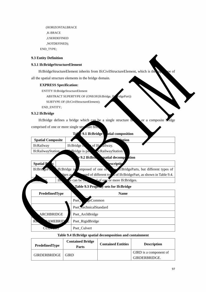
97
(HORIZONTALBRACE
,K-BRACE
,USERDEFINED
,NOTDEFINED);
END_TYPE;
9.3 Entity Definition
9.3.1 IfcBridgeStructureElement
IfcBridgeStructureElement inherits from IfcCivilStructureElement, which is the supertype of
all the spatial structure elements in the bridge domain.
EXPRESS Specification:
ENTITY IfcBridgeStructureElement
ABSTRACT SUPERTYPE OF (ONEOF(IfcBridge, IfcBridgePart))
SUBTYPE OF (IfcCivilStructureElement);
END_ENTITY;
9.3.2 IfcBridge
IfcBridge defines a bridge which can be a single structure bridge or a composite bridge
comprised of one or more single structure bridges.
Table 9.1 IfcBridge spatial composition
Spatial Composite Description
IfcRailway IfcBridge is part of IfcRailway.
IfcRailwayStation IfcBridge is part of IfcRailwayStation.
Table 9.2 IfcBridge spatial decomposition
Spatial Parts Description
IfcBridgePart IfcBridge is composed of one or more IfcBridgeParts, but different types of
bridges are composed of different types of IfcBridgePart, as shown in Table 9.4.
IfcBridge IfcBridge can be composed of one or more IfcBridges.
Table 9.3 Property sets for IfcBridge
PredefinedType Name
Pset_BridgeCommon
Pset_TechnicalStandard
ARCHBRIDGE Pset_ArchBridge
RIGIDFRAMEBRIDGE Pset_RigidBridge
CULVERT Pset_Culvert
Table 9.4 IfcBridge spatial decomposition and containment
PredefinedType Contained Bridge
Parts Contained Entities Description
GIRDERBRIDGE GIRD GIRD is a component of
GIRDERBRIDGE.
CRBIM
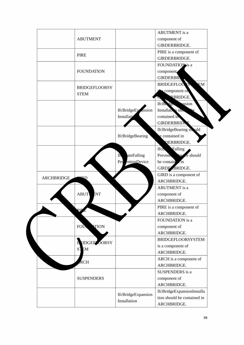
98
ABUTMENT
ABUTMENT is a
component of
GIRDERBRIDGE.
PIRE PIRE is a component of
GIRDERBRIDGE.
FOUNDATION
FOUNDATION is a
component of
GIRDERBRIDGE.
BRIDGEFLOORSY
STEM
BRIDGEFLOORSYSTEM
is a component of
GIRDERBRIDGE.
IfcBridgeExpansion
Installation
IfcBridgeExpansion
Installation should be
contained in
GIRDERBRIDGE.
IfcBridgeBearing
IfcBridgeBearing should
be contained in
GIRDERBRIDGE.
IfcBeamFalling
PreventionDevice
IfcBeamFalling
PreventionDevice should
be contained in
GIRDERBRIDGE.
ARCHBRIDGE GIRD GIRD is a component of
ARCHBRIDGE.
ABUTMENT
ABUTMENT is a
component of
ARCHBRIDGE.
PIRE PIRE is a component of
ARCHBRIDGE.
FOUNDATION
FOUNDATION is a
component of
ARCHBRIDGE.
BRIDGEFLOORSY
STEM
BRIDGEFLOORSYSTEM
is a component of
ARCHBRIDGE.
ARCH ARCH is a component of
ARCHBRIDGE.
SUSPENDERS
SUSPENDERS is a
component of
ARCHBRIDGE.
IfcBridgeExpansion
Installation
IfcBridgeExpansionInstalla
tion should be contained in
ARCHBRIDGE.
CRBIM
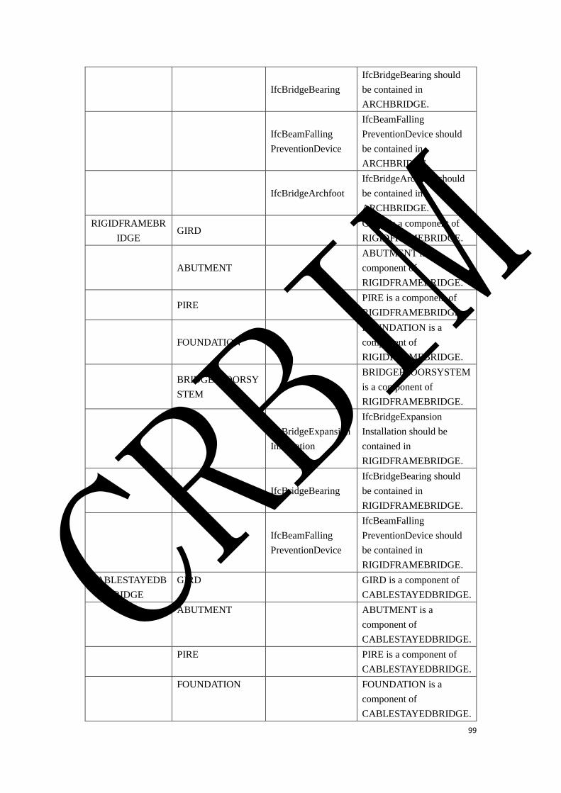
99
IfcBridgeBearing
IfcBridgeBearing should
be contained in
ARCHBRIDGE.
IfcBeamFalling
PreventionDevice
IfcBeamFalling
PreventionDevice should
be contained in
ARCHBRIDGE.
IfcBridgeArchfoot
IfcBridgeArchfoot should
be contained in
ARCHBRIDGE.
RIGIDFRAMEBR
IDGE GIRD
GIRD is a component of
RIGIDFRAMEBRIDGE.
ABUTMENT
ABUTMENT is a
component of
RIGIDFRAMEBRIDGE.
PIRE PIRE is a component of
RIGIDFRAMEBRIDGE.
FOUNDATION
FOUNDATION is a
component of
RIGIDFRAMEBRIDGE.
BRIDGEFLOORSY
STEM
BRIDGEFLOORSYSTEM
is a component of
RIGIDFRAMEBRIDGE.
IfcBridgeExpansion
Installation
IfcBridgeExpansion
Installation should be
contained in
RIGIDFRAMEBRIDGE.
IfcBridgeBearing
IfcBridgeBearing should
be contained in
RIGIDFRAMEBRIDGE.
IfcBeamFalling
PreventionDevice
IfcBeamFalling
PreventionDevice should
be contained in
RIGIDFRAMEBRIDGE.
CABLESTAYEDB
RIDGE
GIRD
GIRD is a component of
CABLESTAYEDBRIDGE.
ABUTMENT
ABUTMENT is a
component of
CABLESTAYEDBRIDGE.
PIRE
PIRE is a component of
CABLESTAYEDBRIDGE.
FOUNDATION
FOUNDATION is a
component of
CABLESTAYEDBRIDGE.
CRBIM
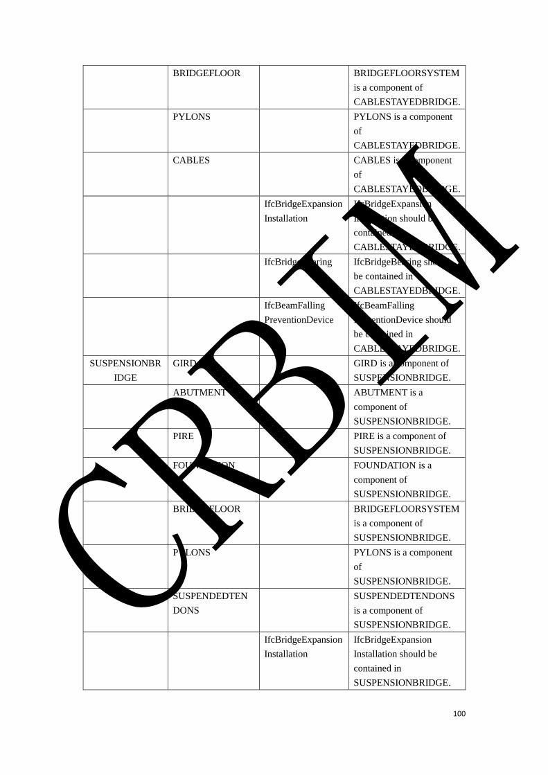
100
BRIDGEFLOOR
BRIDGEFLOORSYSTEM
is a component of
CABLESTAYEDBRIDGE.
PYLONS
PYLONS is a component
of
CABLESTAYEDBRIDGE.
CABLES
CABLES is a component
of
CABLESTAYEDBRIDGE.
IfcBridgeExpansion
Installation
IfcBridgeExpansion
Installation should be
contained in
CABLESTAYEDBRIDGE.
IfcBridgeBearing IfcBridgeBearing should
be contained in
CABLESTAYEDBRIDGE.
IfcBeamFalling
PreventionDevice
IfcBeamFalling
PreventionDevice should
be contained in
CABLESTAYEDBRIDGE.
SUSPENSIONBR
IDGE
GIRD
GIRD is a component of
SUSPENSIONBRIDGE.
ABUTMENT
ABUTMENT is a
component of
SUSPENSIONBRIDGE.
PIRE
PIRE is a component of
SUSPENSIONBRIDGE.
FOUNDATION
FOUNDATION is a
component of
SUSPENSIONBRIDGE.
BRIDGEFLOOR
BRIDGEFLOORSYSTEM
is a component of
SUSPENSIONBRIDGE.
PYLONS
PYLONS is a component
of
SUSPENSIONBRIDGE.
SUSPENDEDTEN
DONS
SUSPENDEDTENDONS
is a component of
SUSPENSIONBRIDGE.
IfcBridgeExpansion
Installation
IfcBridgeExpansion
Installation should be
contained in
SUSPENSIONBRIDGE.
CRBIM
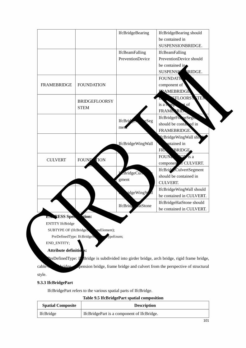
101
IfcBridgeBearing IfcBridgeBearing should
be contained in
SUSPENSIONBRIDGE.
IfcBeamFalling
PreventionDevice
IfcBeamFalling
PreventionDevice should
be contained in
SUSPENSIONBRIDGE.
FRAMEBRIDGE FOUNDATION
FOUNDATION is a
component of
FRAMEBRIDGE.
BRIDGEFLOORSY
STEM
BRIDGEFLOORSYSTEM
is a component of
FRAMEBRIDGE.
IfcBridgeFrameSeg
ment
IfcBridgeFrameSegment
should be contained in
FRAMEBRIDGE.
IfcBridgeWingWall
IfcBridgeWingWall should
be contained in
FRAMEBRIDGE.
CULVERT FOUNDATION FOUNDATION is a
component of CULVERT.
IfcBridgeCulvertSe
gment
IfcBridgeCulvertSegment
should be contained in
CULVERT.
IfcBridgeWingWall IfcBridgeWingWall should
be contained in CULVERT.
IfcBridgeHatStone IfcBridgeHatStone should
be contained in CULVERT.
EXPRESS Specification:
ENTITY IfcBridge
SUBTYPE OF (IfcBridgeStructureElement);
PreDefinedType: IfcBridgeStructureTypeEnum;
END_ENTITY;
Attribute definitions:
PreDefinedType: IfcBridge is subdivided into girder bridge, arch bridge, rigid frame bridge,
cable-stayed bridge, suspension bridge, frame bridge and culvert from the perspective of structural
style.
9.3.3 IfcBridgePart
IfcBridgePart refers to the various spatial parts of IfcBridge.
Table 9.5 IfcBridgePart spatial composition
Spatial Composite Description
IfcBridge IfcBridgePart is a component of IfcBridge.
CRBIM
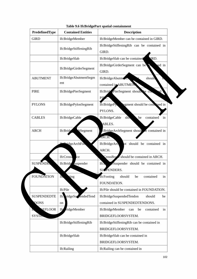
102
Table 9.6 IfcBridgePart spatial containment
PredefinedType Contained Entities Description
GIRD IfcBridgeMember IfcBridgeMember can be contained in GIRD.
IfcBridgeStiffeningRib
IfcBridgeStiffeningRib can be contained in
GIRD.
IfcBridgeSlab IfcBridgeSlab can be contained in GIRD.
IfcBridgeGirderSegment
IfcBridgeGirderSegment can be contained in
GIRD.
ABUTMENT IfcBridgeAbutmentSegm
ent
IfcBridgeAbutmentSegment should be
contained in ABUTMENT.
PIRE IfcBridgePierSegment IfcBridgePierSegment should be contained in
PIRE.
PYLONS IfcBridgePylonSegment IfcBridgePylonSegment should be contained in
PYLONS.
CABLES IfcBridgeCable IfcBridgeCable should be contained in
CABLES.
ARCH IfcBridgeArchSegment IfcBridgeArchSegment should be contained in
ARCH.
IfcBridgeArchFoot IfcBridgeArchFoot should be contained in
ARCH.
IfcCrossBrace IfcCrossBrace should be contained in ARCH.
SUSPENDERS IfcBridgeSuspender IfcBridgeSuspender should be contained in
SUSPENDERS.
FOUNDATION IfcFooting IfcFooting should be contained in
FOUNDATION.
IfcPile IfcPile should be contained in FOUNDATION.
SUSPENDEDTE
NDONS
IfcBridgeSuspendedTend
on
IfcBridgeSuspendedTendon should be
contained in SUSPENDEDTENDONS.
BRIDGEFLOOR
SYSTEM
IfcBridgeMember IfcBridgeMember can be contained in
BRIDGEFLOORSYSTEM.
IfcBridgeStiffeningRib IfcBridgeStiffeningRib can be contained in
BRIDGEFLOORSYSTEM.
IfcBridgeSlab IfcBridgeSlab can be contained in
BRIDGEFLOORSYSTEM.
IfcRailing IfcRailing can be contained in
CRBIM

103
BRIDGEFLOORSYSTEM.
IfcBridgeRefugePlatform IfcBridgeRefugePlatform can be contained in
BRIDGEFLOORSYSTEM.
Table 9.7 Property sets for IfcBridgePart
PredefinedType Name
GIRD Pset_TechnicalIndex
ABUTMENT Pset_Abutment
PIRE Pset_BridgePier
EXPRESS Specification:
ENTITY IfcBridgePart
SUBTYPE OF (IfcBridgeStructureElement);
PreDefinedType: IfcBridgeStructurePartTypeEnum;
END_ENTITY;
Attribute definitions:
PreDefinedType: IfcBridgePart includes GIRD, ABUTMENT, PIER, PYLONS, CABLES,
ARCH, SUSPENDERS, FOUNDATION, SUSPENDEDTENDONS and
BRIDGEFLOORSYSTEM.
9.3.4 IfcBridgeElement
IfcBridgeElement is derived from the IfcCivilElement, which is the supertype of all physical
elements in bridge engineering.
Table 9.8 IfcBridgeElement contained in spatial structure
Spatial Structure Description
IfcBridge IfcBridgeElement is a component of IfcBridge. Some of
IfcBridgeElement can be directly contained in IfcBridge.
IfcBridgePart IfcBridgeElement is a component of IfcBridgePart. Some of
IfcBridgeElement should be contained in IfcBridgePart, but some of
IfcBridgeElement can also be directly contained in IfcBridge.
EXPRESS Specification:
ENTITY IfcBridgeElement
ABSTRACT SUPERTYPE OF(ONEOF(IfcBridgeMember,IfcStiffeningRib,IfcBridgeSlab,
IfcBridgeGirderSegment,IfcBridgeGearBlocks,IfcBridgeBedstone,IfcBridgePierSegment,IfcBridgeAbutmentSegm
ent,IfcBridgePylon,IfcBridgeArchrib,IfcBridgeArchfoot,IfcBridgeStandColumn,IfcBridgeSuspender,IfcBridgeCab
le,IfcBridgeSuspendedTendon,IfcBridgeBearing,IfcBridgeExpansionInstallation,IfcBridgeProtectingWall,IfcBridg
eFrameSegment,IfcBridgeWingWall,IfcBridgeCulvertSegment,IfcBridgeHatStone,IfcBridgeCoping,IfcBridge
EmbeddedPartsFoundation,IfcBridgeRefugePlatform))
SUBTYPE OF (IfcCivilElement);
END_ENTITY;
9.3.5 IfcBridgeMember
CRBIM

104
IfcBridgeMember mainly refers to the members comprising the structure, such as truss
member, longitudinal beam, cross beam, etc.
Table 9.9 IfcBridgeMember contained in spatial structure
Spatial Structure Description
IfcBridgePart\GIRD IfcBridgeMember can be contained in IfcBridgePart\GIRD.
IfcBridgePart\PYLONS IfcBridgeMember can be contained in IfcBridgePart\
PYLONS.
IfcBridgePart\ARCH IfcBridgeMember can be contained in IfcBridgePart\ARCH.
IfcBridgePart\BRIDGEFLOOR
SYSTEM
IfcBridgeMember can be contained in IfcBridgePart\
BRIDGEFLOORSYSTEM.
EXPRESS Specification:
ENTITY IfcBridgeMember
SUBTYPE OF (IfcBridgeElement);
PreDefinedType: IfcBridgeMemberTypeEnum;
END_ENTITY;
Attribute definitions:
PreDefinedType: Currently it only includes USERDEFINED and NOTDEFINED.
9.3.6 IfcBridgeStiffeningRib
IfcBridgeStiffeningRib mainly refers to U-type rib, plate rib and other stiffening structures.
Table 9.10 IfcBridgeStiffeningRib contained in spatial structure
Spatial Structure Description
IfcBridgePart\GIRD IfcBridgeStiffeningRib can be contained in IfcBridgePart\
GIRD.
IfcBridgePart\PYLONS IfcBridgeStiffeningRib can be contained in IfcBridgePart\
PYLONS.
IfcBridgePart\ARCH IfcBridgeStiffeningRib can be contained in IfcBridgePart\
ARCH.
IfcBridgePart\BRIDGEFLOOR
SYSTEM
IfcBridgeStiffeningRib can be contained in IfcBridgePart\
BRIDGEFLOORSYSTEM.
EXPRESS Specification:
ENTITY IfcBridgeStiffeningRib
SUBTYPE OF (IfcBridgeElement);
PreDefinedType: IfcBridgeStiffeningRibTypeEnum;
END_ENTITY;
Attribute definitions:
PreDefinedType: Currently it only includes USERDEFINED and NOTDEFINED.
9.3.7 IfcBridgeSlab
CRBIM
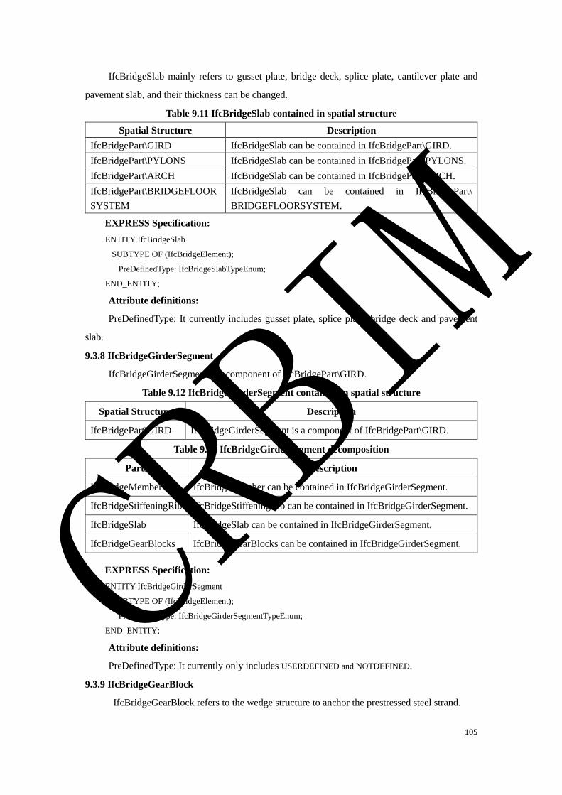
105
IfcBridgeSlab mainly refers to gusset plate, bridge deck, splice plate, cantilever plate and
pavement slab, and their thickness can be changed.
Table 9.11 IfcBridgeSlab contained in spatial structure
Spatial Structure Description
IfcBridgePart\GIRD IfcBridgeSlab can be contained in IfcBridgePart\GIRD.
IfcBridgePart\PYLONS IfcBridgeSlab can be contained in IfcBridgePart\PYLONS.
IfcBridgePart\ARCH IfcBridgeSlab can be contained in IfcBridgePart\ARCH.
IfcBridgePart\BRIDGEFLOOR
SYSTEM
IfcBridgeSlab can be contained in IfcBridgePart\
BRIDGEFLOORSYSTEM.
EXPRESS Specification:
ENTITY IfcBridgeSlab
SUBTYPE OF (IfcBridgeElement);
PreDefinedType: IfcBridgeSlabTypeEnum;
END_ENTITY;
Attribute definitions:
PreDefinedType: It currently includes gusset plate, splice plate, bridge deck and pavement
slab.
9.3.8 IfcBridgeGirderSegment
IfcBridgeGirderSegment is a component of IfcBridgePart\GIRD.
Table 9.12 IfcBridgeGirderSegment contained in spatial structure
Spatial Structure Description
IfcBridgePart\GIRD IfcBridgeGirderSegment is a component of IfcBridgePart\GIRD.
Table 9.13 IfcBridgeGirderSegment decomposition
Parts Description
IfcBridgeMember IfcBridgeMember can be contained in IfcBridgeGirderSegment.
IfcBridgeStiffeningRib IfcBridgeStiffeningRib can be contained in IfcBridgeGirderSegment.
IfcBridgeSlab IfcBridgeSlab can be contained in IfcBridgeGirderSegment.
IfcBridgeGearBlocks IfcBridgeGearBlocks can be contained in IfcBridgeGirderSegment.
EXPRESS Specification:
ENTITY IfcBridgeGirderSegment
SUBTYPE OF (IfcBridgeElement);
PreDefinedType: IfcBridgeGirderSegmentTypeEnum;
END_ENTITY;
Attribute definitions:
PreDefinedType: It currently only includes USERDEFINED and NOTDEFINED.
9.3.9 IfcBridgeGearBlock
IfcBridgeGearBlock refers to the wedge structure to anchor the prestressed steel strand.
CRBIM
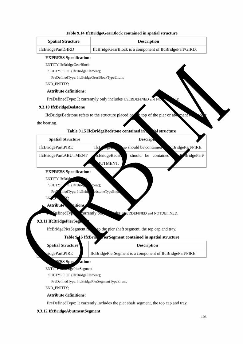
106
Table 9.14 IfcBridgeGearBlock contained in spatial structure
Spatial Structure Description
IfcBridgePart\GIRD IfcBridgeGearBlock is a component of IfcBridgePart\GIRD.
EXPRESS Specification:
ENTITY IfcBridgeGearBlock
SUBTYPE OF (IfcBridgeElement);
PreDefinedType: IfcBridgeGearBlockTypeEnum;
END_ENTITY;
Attribute definitions:
PreDefinedType: It currentyly only includes USERDEFINED and NOTDEFINED.
9.3.10 IfcBridgeBedstone
IfcBridgeBedstone refers to the structure placed on the top of the pier or abutment to support
the bearing.
Table 9.15 IfcBridgeBedstone contained in spatial structure
Spatial Structure Description
IfcBridgePart\PIRE IfcBridgeBedstone should be contained in IfcBridgePart\PIRE.
IfcBridgePart\ABUTMENT IfcBridgeBedstone should be contained in IfcBridgePart\
ABUTMENT.
EXPRESS Specification:
ENTITY IfcBridgeBedstone
SUBTYPE OF (IfcBridgeElement);
PreDefinedType: IfcBridgeBedstoneTypeEnum;
END_ENTITY;
Attribute definitions:
PreDefinedType: It currently only includes USERDEFINED and NOTDEFINED.
9.3.11 IfcBridgePierSegment
IfcBridgePierSegment refers to the pier shaft segment, the top cap and tray.
Table 9.16 IfcBridgePierSegment contained in spatial structure
Spatial Structure Description
IfcBridgePart\PIRE IfcBridgePierSegment is a component of IfcBridgePart\PIRE.
EXPRESS Specification:
ENTITY IfcBridgePierSegment
SUBTYPE OF (IfcBridgeElement);
PreDefinedType: IfcBridgePierSegmentTypeEnum;
END_ENTITY;
Attribute definitions:
PreDefinedType: It currently includes the pier shaft segment, the top cap and tray.
9.3.12 IfcBridgeAbutmentSegment
CRBIM
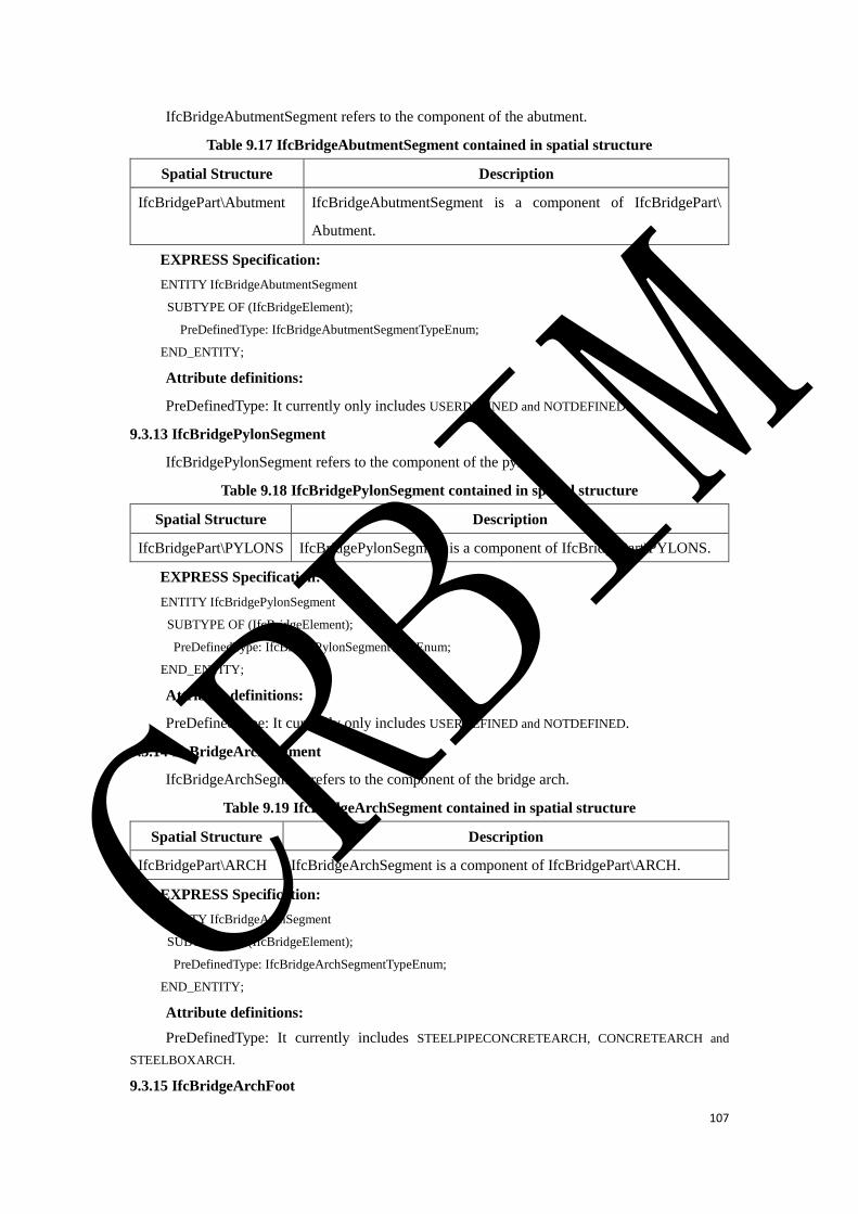
107
IfcBridgeAbutmentSegment refers to the component of the abutment.
Table 9.17 IfcBridgeAbutmentSegment contained in spatial structure
Spatial Structure Description
IfcBridgePart\Abutment IfcBridgeAbutmentSegment is a component of IfcBridgePart\
Abutment.
EXPRESS Specification:
ENTITY IfcBridgeAbutmentSegment
SUBTYPE OF (IfcBridgeElement);
PreDefinedType: IfcBridgeAbutmentSegmentTypeEnum;
END_ENTITY;
Attribute definitions:
PreDefinedType: It currently only includes USERDEFINED and NOTDEFINED.
9.3.13 IfcBridgePylonSegment
IfcBridgePylonSegment refers to the component of the pylon.
Table 9.18 IfcBridgePylonSegment contained in spatial structure
Spatial Structure Description
IfcBridgePart\PYLONS IfcBridgePylonSegment is a component of IfcBridgePart\PYLONS.
EXPRESS Specification:
ENTITY IfcBridgePylonSegment
SUBTYPE OF (IfcBridgeElement);
PreDefinedType: IfcBridgePylonSegmentTypeEnum;
END_ENTITY;
Attribute definitions:
PreDefinedType: It currently only includes USERDEFINED and NOTDEFINED.
9.3.14 IfcBridgeArchSegment
IfcBridgeArchSegment refers to the component of the bridge arch.
Table 9.19 IfcBridgeArchSegment contained in spatial structure
Spatial Structure Description
IfcBridgePart\ARCH IfcBridgeArchSegment is a component of IfcBridgePart\ARCH.
EXPRESS Specification:
ENTITY IfcBridgeArchSegment
SUBTYPE OF (IfcBridgeElement);
PreDefinedType: IfcBridgeArchSegmentTypeEnum;
END_ENTITY;
Attribute definitions:
PreDefinedType: It currently includes STEELPIPECONCRETEARCH, CONCRETEARCH and
STEELBOXARCH.
9.3.15 IfcBridgeArchFoot
CRBIM
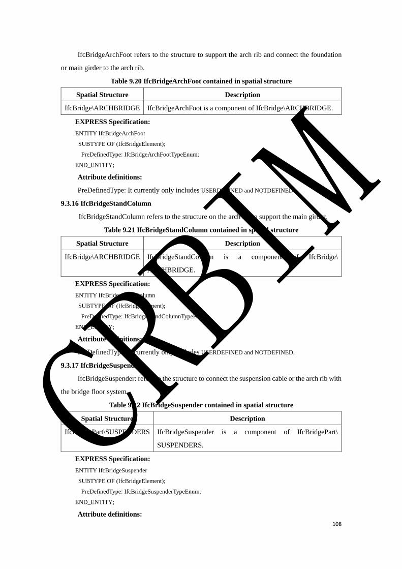
108
IfcBridgeArchFoot refers to the structure to support the arch rib and connect the foundation
or main girder to the arch rib.
Table 9.20 IfcBridgeArchFoot contained in spatial structure
Spatial Structure Description
IfcBridge\ARCHBRIDGE IfcBridgeArchFoot is a component of IfcBridge\ARCHBRIDGE.
EXPRESS Specification:
ENTITY IfcBridgeArchFoot
SUBTYPE OF (IfcBridgeElement);
PreDefinedType: IfcBridgeArchFootTypeEnum;
END_ENTITY;
Attribute definitions:
PreDefinedType: It currently only includes USERDEFINED and NOTDEFINED.
9.3.16 IfcBridgeStandColumn
IfcBridgeStandColumn refers to the structure on the arch rib to support the main girder.
Table 9.21 IfcBridgeStandColumn contained in spatial structure
Spatial Structure Description
IfcBridge\ARCHBRIDGE IfcBridgeStandColumn is a component of IfcBridge\
ARCHBRIDGE.
EXPRESS Specification:
ENTITY IfcBridgeStandColumn
SUBTYPE OF (IfcBridgeElement);
PreDefinedType: IfcBridgeStandColumnTypeEnum;
END_ENTITY;
Attribute definitions:
PreDefinedType: It currently only includes USERDEFINED and NOTDEFINED.
9.3.17 IfcBridgeSuspender
IfcBridgeSuspender: refers to the structure to connect the suspension cable or the arch rib with
the bridge floor system.
Table 9.22 IfcBridgeSuspender contained in spatial structure
Spatial Structure Description
IfcBridgePart\SUSPENDERS IfcBridgeSuspender is a component of IfcBridgePart\
SUSPENDERS.
EXPRESS Specification:
ENTITY IfcBridgeSuspender
SUBTYPE OF (IfcBridgeElement);
PreDefinedType: IfcBridgeSuspenderTypeEnum;
END_ENTITY;
Attribute definitions:
CRBIM
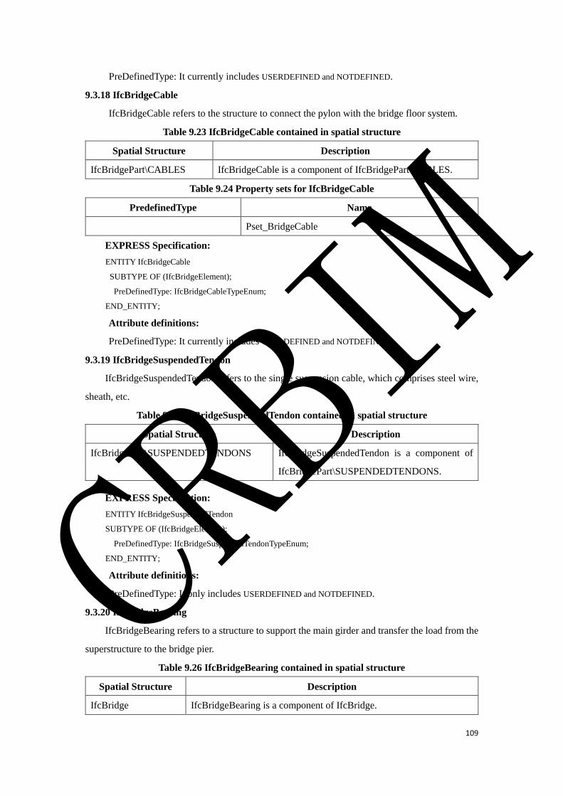
109
PreDefinedType: It currently includes USERDEFINED and NOTDEFINED.
9.3.18 IfcBridgeCable
IfcBridgeCable refers to the structure to connect the pylon with the bridge floor system.
Table 9.23 IfcBridgeCable contained in spatial structure
Spatial Structure Description
IfcBridgePart\CABLES IfcBridgeCable is a component of IfcBridgePart\CABLES.
Table 9.24 Property sets for IfcBridgeCable
PredefinedType Name
Pset_BridgeCable
EXPRESS Specification:
ENTITY IfcBridgeCable
SUBTYPE OF (IfcBridgeElement);
PreDefinedType: IfcBridgeCableTypeEnum;
END_ENTITY;
Attribute definitions:
PreDefinedType: It currently includes USERDEFINED and NOTDEFINED.
9.3.19 IfcBridgeSuspendedTendon
IfcBridgeSuspendedTendon refers to the single suspension cable, which comprises steel wire,
sheath, etc.
Table 9.25 IfcBridgeSuspendedTendon contained in spatial structure
Spatial Structure Description
IfcBridgePart\SUSPENDEDTENDONS IfcBridgeSuspendedTendon is a component of
IfcBridgePart\SUSPENDEDTENDONS.
EXPRESS Specification:
ENTITY IfcBridgeSuspendedTendon
SUBTYPE OF (IfcBridgeElement);
PreDefinedType: IfcBridgeSuspendedTendonTypeEnum;
END_ENTITY;
Attribute definitions:
PreDefinedType: It only includes USERDEFINED and NOTDEFINED.
9.3.20 IfcBridgeBearing
IfcBridgeBearing refers to a structure to support the main girder and transfer the load from the
superstructure to the bridge pier.
Table 9.26 IfcBridgeBearing contained in spatial structure
Spatial Structure Description
IfcBridge IfcBridgeBearing is a component of IfcBridge.
CRBIM

110
Table 9.27 Property sets for IfcBridgeBearing
PredefinedType Name
Pset_BridgeBearing
EXPRESS Specification:
ENTITY IfcBridgeBearing
SUBTYPE OF (IfcBridgeElement);
PreDefinedType: IfcBridgeBearingTypeEnum;
END_ENTITY;
Attribute definitions:
PreDefinedType: IfcBridgeBearing is subdivided into BASINRUBBERSUPPORT,
LAMINATEDRUBBERBEARING and STEELBEARING.
9.3.21 IfcBridgeExpansionInstallation
IfcBridgeExpansionInstallation refers to the structure installed on between two main girders
to facilitate the vehicle smoothly pass the bridge deck and to meet the deformation of the upper
structure of the bridge. It is comprised of rubber and steel parts.
Table 9.28 IfcBridgeExpansionInstallation contained in spatial structure
Spatial Structure Description
IfcBridge IfcBridgeExpansionInstallation is a component of IfcBridge.
Table 9.29 Property sets for IfcBridgeExpansionInstallation
PredefinedType Name
Pset_ExpansionInstallation
EXPRESS Specification:
ENTITY IfcBridgeExpansionInstallation
SUBTYPE OF (IfcBridgeElement);
PreDefinedType: IfcBridgeExpansionInstallationTypeEnum;
END_ENTITY;
Attribute definitions:
PreDefinedType: It currently includes USERDEFINED and NOTDEFINED.
9.3.22 IfcBridgeProtectingWall
IfcBridgeProtectingWall refers to the structure located on the bridge deck to protect the
pedestrians and to retain ballast.
Table 9.30 IfcBridgeProtectingWall contained in spatial structure
Spatial Structure Description
IfcBridgePart\BRIDGEFLOORSYSTEM IfcBridgeProtectingWall is a component of
IfcBridgePart\BRIDGEFLOORSYSTEM.
EXPRESS Specification:
ENTITY IfcBridgeProtectingWall
SUBTYPE OF (IfcBridgeElement);
CRBIM

111
PreDefinedType: IfcBridgeProtectingWallTypeEnum;
END_ENTITY;
Attribute definitions:
PreDefinedType: It currently includes USERDEFINED and NOTDEFINED.
9.3.23 IfcFrameSegment
IfcFrameSegment refers to a segment of a frame bridge.
Table 9.31 IfcFrameSegment contained in spatial structure
Spatial Structure Description
IfcBridge\FRAMEBRIDGE IfcFrameSegment is a component of
IfcBridge\FRAMEBRIDGE.
EXPRESS Specification:
ENTITY IfcFrameSegment
SUBTYPE OF (IfcBridgeElement);
PreDefinedType: IfcFrameSegmentWallTypeEnum;
END_ENTITY;
Attribute definitions:
PreDefinedType: It currently includes USERDEFINED and NOTDEFINED.
9.3.24 IfcBridgeWingWall
IfcBridgeWingWall refers to the structure on the inlet and outlet of culvert and a frame bridge
to ensure the two sides of the embankment slope stability and to guide the river.
Table 9.32 IfcBridgeWingWall contained in spatial structure
Spatial Structure Description
IfcBridge\FRAMEBRIDGE IfcBridgeWingWall is a component of IfcBridge\
FRAMEBRIDGE.
IfcBridge\CULVERT IfcBridgeWingWall is a component of IfcBridge\CULVERT.
EXPRESS Specification:
ENTITY IfcBridgeWingWall
SUBTYPE OF (IfcBridgeElement);
PreDefinedType: IfcBridgeWingWallTypeEnum;
END_ENTITY;
Attribute definitions:
PreDefinedType: It currently includes USERDEFINED and NOTDEFINED.
9.3.25 IfcBridgeCulvertSegment
IfcBridgeCulvertSegment refers to a segment of a culvert.
Table 9.33 IfcBridgeCulvertSegment contained in spatial structure
Spatial Structure Description
IfcBridge\CULVERT IfcBridgeCulvertSegment is a component of IfcBridge\CULVERT.
CRBIM
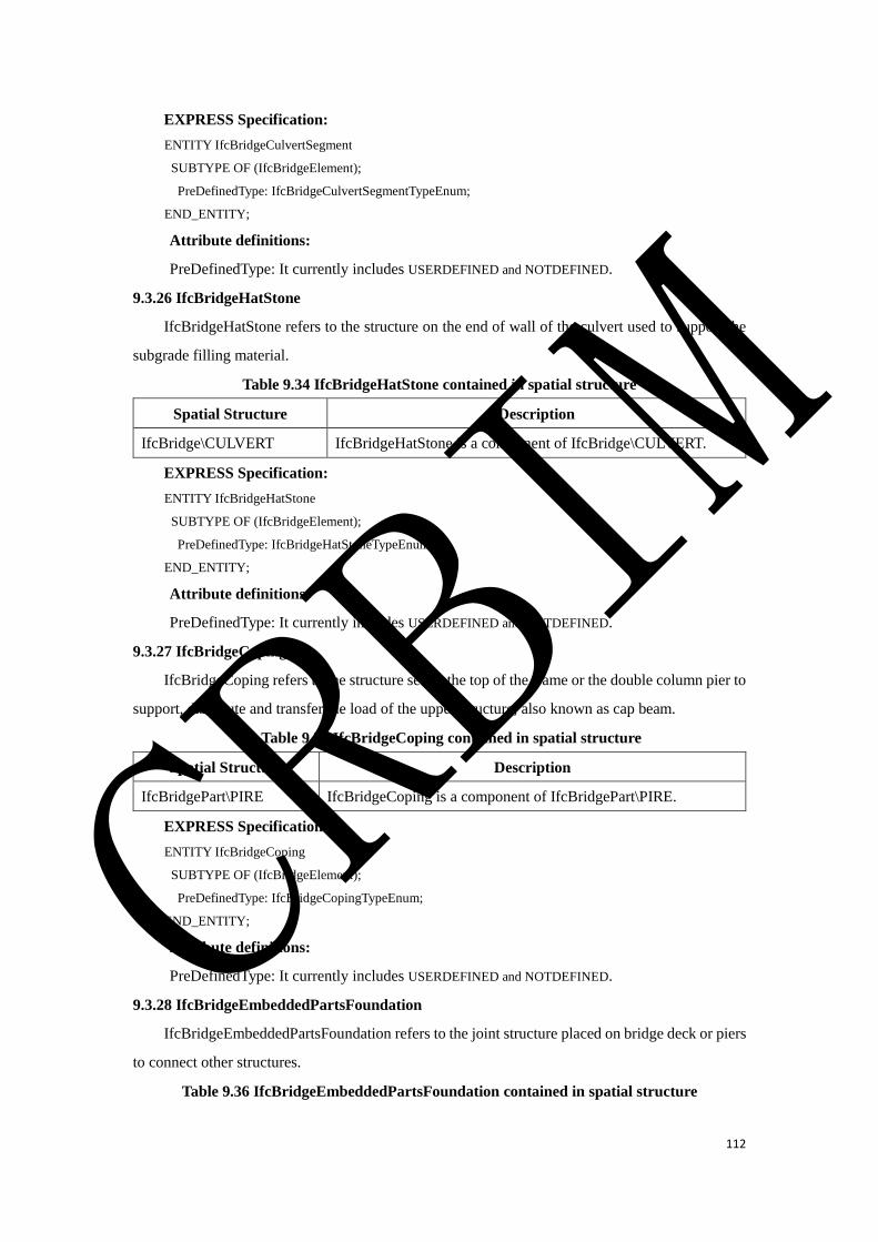
112
EXPRESS Specification:
ENTITY IfcBridgeCulvertSegment
SUBTYPE OF (IfcBridgeElement);
PreDefinedType: IfcBridgeCulvertSegmentTypeEnum;
END_ENTITY;
Attribute definitions:
PreDefinedType: It currently includes USERDEFINED and NOTDEFINED.
9.3.26 IfcBridgeHatStone
IfcBridgeHatStone refers to the structure on the end of wall of the culvert used to support the
subgrade filling material.
Table 9.34 IfcBridgeHatStone contained in spatial structure
Spatial Structure Description
IfcBridge\CULVERT IfcBridgeHatStone is a component of IfcBridge\CULVERT.
EXPRESS Specification:
ENTITY IfcBridgeHatStone
SUBTYPE OF (IfcBridgeElement);
PreDefinedType: IfcBridgeHatStoneTypeEnum;
END_ENTITY;
Attribute definitions:
PreDefinedType: It currently includes USERDEFINED and NOTDEFINED.
9.3.27 IfcBridgeCoping
IfcBridgeCoping refers to the structure set on the top of the frame or the double column pier to
support, distribute and transfer the load of the upper structure, also known as cap beam.
Table 9.35 IfcBridgeCoping contained in spatial structure
Spatial Structure Description
IfcBridgePart\PIRE IfcBridgeCoping is a component of IfcBridgePart\PIRE.
EXPRESS Specification:
ENTITY IfcBridgeCoping
SUBTYPE OF (IfcBridgeElement);
PreDefinedType: IfcBridgeCopingTypeEnum;
END_ENTITY;
Attribute definitions:
PreDefinedType: It currently includes USERDEFINED and NOTDEFINED.
9.3.28 IfcBridgeEmbeddedPartsFoundation
IfcBridgeEmbeddedPartsFoundation refers to the joint structure placed on bridge deck or piers
to connect other structures.
Table 9.36 IfcBridgeEmbeddedPartsFoundation contained in spatial structure
CRBIM
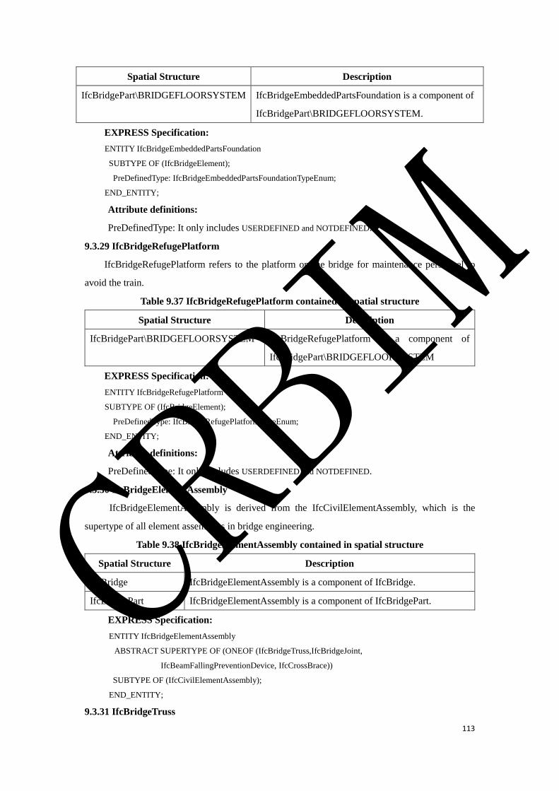
113
Spatial Structure Description
IfcBridgePart\BRIDGEFLOORSYSTEM IfcBridgeEmbeddedPartsFoundation is a component of
IfcBridgePart\BRIDGEFLOORSYSTEM.
EXPRESS Specification:
ENTITY IfcBridgeEmbeddedPartsFoundation
SUBTYPE OF (IfcBridgeElement);
PreDefinedType: IfcBridgeEmbeddedPartsFoundationTypeEnum;
END_ENTITY;
Attribute definitions:
PreDefinedType: It only includes USERDEFINED and NOTDEFINED.
9.3.29 IfcBridgeRefugePlatform
IfcBridgeRefugePlatform refers to the platform on the bridge for maintenance personnel to
avoid the train.
Table 9.37 IfcBridgeRefugePlatform contained in spatial structure
Spatial Structure Description
IfcBridgePart\BRIDGEFLOORSYSTEM IfcBridgeRefugePlatform is a component of
IfcBridgePart\BRIDGEFLOORSYSTEM
EXPRESS Specification:
ENTITY IfcBridgeRefugePlatform
SUBTYPE OF (IfcBridgeElement);
PreDefinedType: IfcBridgeRefugePlatformTypeEnum;
END_ENTITY;
Attribute definitions:
PreDefinedType: It only includes USERDEFINED and NOTDEFINED.
9.3.30 IfcBridgeElementAssembly
IfcBridgeElementAssembly is derived from the IfcCivilElementAssembly, which is the
supertype of all element assemblies in bridge engineering.
Table 9.38 IfcBridgeElementAssembly contained in spatial structure
Spatial Structure Description
IfcBridge IfcBridgeElementAssembly is a component of IfcBridge.
IfcBridgePart IfcBridgeElementAssembly is a component of IfcBridgePart.
EXPRESS Specification:
ENTITY IfcBridgeElementAssembly
ABSTRACT SUPERTYPE OF (ONEOF (IfcBridgeTruss,IfcBridgeJoint,
IfcBeamFallingPreventionDevice, IfcCrossBrace))
SUBTYPE OF (IfcCivilElementAssembly);
END_ENTITY;
9.3.31 IfcBridgeTruss
CRBIM
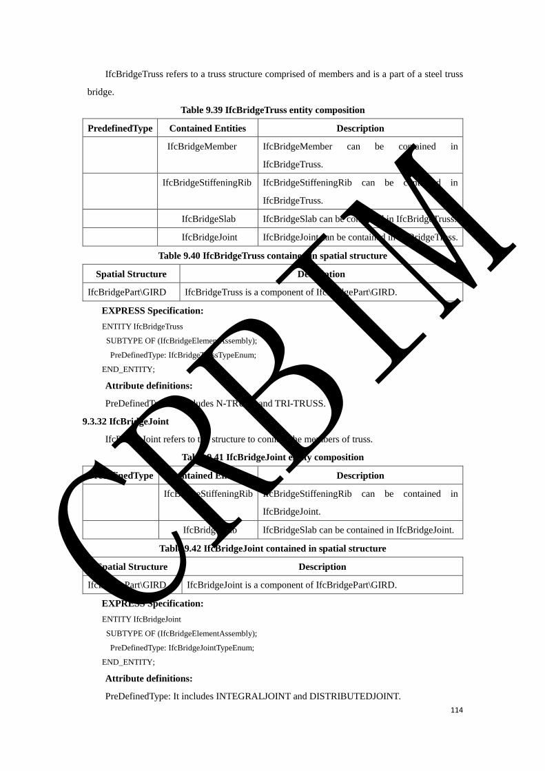
114
IfcBridgeTruss refers to a truss structure comprised of members and is a part of a steel truss
bridge.
Table 9.39 IfcBridgeTruss entity composition
PredefinedType Contained Entities Description
IfcBridgeMember IfcBridgeMember can be contained in
IfcBridgeTruss.
IfcBridgeStiffeningRib IfcBridgeStiffeningRib can be contained in
IfcBridgeTruss.
IfcBridgeSlab IfcBridgeSlab can be contained in IfcBridgeTruss.
IfcBridgeJoint IfcBridgeJoint can be contained in IfcBridgeTruss.
Table 9.40 IfcBridgeTruss contained in spatial structure
Spatial Structure Description
IfcBridgePart\GIRD IfcBridgeTruss is a component of IfcBridgePart\GIRD.
EXPRESS Specification:
ENTITY IfcBridgeTruss
SUBTYPE OF (IfcBridgeElementAssembly);
PreDefinedType: IfcBridgeTrussTypeEnum;
END_ENTITY;
Attribute definitions:
PreDefinedType: It includes N-TRUSS and TRI-TRUSS.
9.3.32 IfcBridgeJoint
IfcBridgeJoint refers to the structure to connect the members of truss.
Table 9.41 IfcBridgeJoint entity composition
PredefinedType Contained Entities Description
IfcBridgeStiffeningRib IfcBridgeStiffeningRib can be contained in
IfcBridgeJoint.
IfcBridgeSlab IfcBridgeSlab can be contained in IfcBridgeJoint.
Table 9.42 IfcBridgeJoint contained in spatial structure
Spatial Structure Description
IfcBridgePart\GIRD IfcBridgeJoint is a component of IfcBridgePart\GIRD.
EXPRESS Specification:
ENTITY IfcBridgeJoint
SUBTYPE OF (IfcBridgeElementAssembly);
PreDefinedType: IfcBridgeJointTypeEnum;
END_ENTITY;
Attribute definitions:
PreDefinedType: It includes INTEGRALJOINT and DISTRIBUTEDJOINT.
CRBIM
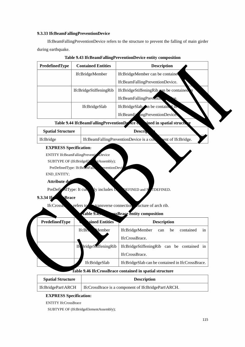
115
9.3.33 IfcBeamFallingPreventionDevice
IfcBeamFallingPreventionDevice refers to the structure to prevent the falling of main girder
during earthquake.
Table 9.43 IfcBeamFallingPreventionDevice entity composition
PredefinedType Contained Entities Description
IfcBridgeMember IfcBridgeMember can be contained in
IfcBeamFallingPreventionDevice.
IfcBridgeStiffeningRib IfcBridgeStiffeningRib can be contained in
IfcBeamFallingPreventionDevice.
IfcBridgeSlab IfcBridgeSlab can be contained in
IfcBeamFallingPreventionDevice.
Table 9.44 IfcBeamFallingPreventionDevice contained in spatial structure
Spatial Structure Description
IfcBridge IfcBeamFallingPreventionDevice is a component of IfcBridge.
EXPRESS Specification:
ENTITY IfcBeamFallingPreventionDevice
SUBTYPE OF (IfcBridgeElementAssembly);
PreDefinedType: IfcBeamFallingPreventionDeviceTypeEnum;
END_ENTITY;
Attribute definitions:
PreDefinedType: It currently includes USERDEFINED and NOTDEFINED.
9.3.34 IfcCrossBrace
IfcCrossBrace refers to the transverse connection structure of arch rib.
Table 9.45 IfcCrossBrace entity composition
PredefinedType Contained Entities Description
IfcBridgeMember IfcBridgeMember can be contained in
IfcCrossBrace.
IfcBridgeStiffeningRib IfcBridgeStiffeningRib can be contained in
IfcCrossBrace.
IfcBridgeSlab IfcBridgeSlab can be contained in IfcCrossBrace.
Table 9.46 IfcCrossBrace contained in spatial structure
Spatial Structure Description
IfcBridgePart\ARCH IfcCrossBrace is a component of IfcBridgePart\ARCH.
EXPRESS Specification:
ENTITY IfcCrossBrace
SUBTYPE OF (IfcBridgeElementAssembly);
CRBIM
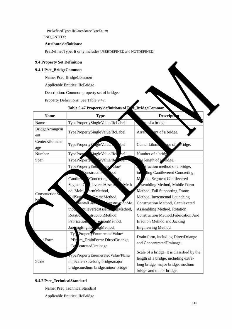
116
PreDefinedType: IfcCrossBraceTypeEnum;
END_ENTITY;
Attribute definitions:
PreDefinedType: It only includes USERDEFINED and NOTDEFINED.
9.4 Property Set Definition
9.4.1 Pset_BridgeCommon
Name: Pset_BridgeCommon
Applicable Entities: IfcBridge
Description: Common property set of bridge.
Property Definitions: See Table 9.47.
Table 9.47 Property definitions of Pset_BridgeCommon
Name Type Description
Name TypePropertySingleValue/IfcLabel Name of a bridge.
BridgeArrangem
ent TypePropertySingleValue/IfcLabel Arrangement of a bridge.
CenterKilometer
age TypePropertySingleValue/IfcLabel Center kilometer age of a bridge.
Number TypePropertySingleValue/IfcLabel Number of a bridge.
Span TypePropertySingleValue/IfcLabel The length of a bridge.
ConstructionMet
hod
TypePropertyEnumeratedValue/
PEnum_ConstructionMethod:
CantileveredConcretingMethod,
SegmentCantileveredAssemblingMeth
od, MobileFormMethod,
FullSupportingFrameMethod,
IncrementalLaunchingConstructionMe
thod, CantileveredAssemblingMethod,
RotationConstructionMethod,
FabricationAndErectionMethod,
JackingEngineeringMethod.
Construction method of a bridge,
including Cantilevered Concreting
Method, Segment Cantilevered
Assembling Method, Mobile Form
Method, Full Supporting Frame
Method, Incremental Launching
Construction Method, Cantilevered
Assembling Method, Rotation
Construction Method,Fabrication And
Erection Method and Jacking
Engineering Method.
DrainForm
TypePropertyEnumeratedValue/
PEnum_DrainForm: DirectDriange,
ConcentratedDrainage
Drain form, including DirectDriange
and ConcentratedDrainage.
Scale
TypePropertyEnumeratedValue/PEnu
m_Scale:extra-long bridge,major
bridge,medium bridge,minor bridge
Scale of a bridge. It is classified by the
length of a bridge, including extra-
long bridge, major bridge, medium
bridge and minor bridge.
9.4.2 Pset_TechnicalStandard
Name: Pset_TechnicalStandard
Applicable Entities: IfcBridge
CRBIM
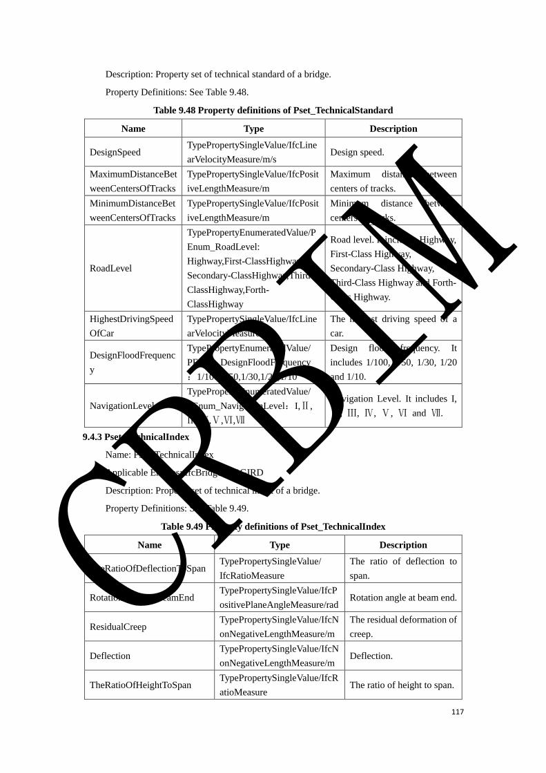
117
Description: Property set of technical standard of a bridge.
Property Definitions: See Table 9.48.
Table 9.48 Property definitions of Pset_TechnicalStandard
Name Type Description
DesignSpeed TypePropertySingleValue/IfcLine
arVelocityMeasure/m/s Design speed.
MaximumDistanceBet
weenCentersOfTracks
TypePropertySingleValue/IfcPosit
iveLengthMeasure/m
Maximum distance between
centers of tracks.
MinimumDistanceBet
weenCentersOfTracks
TypePropertySingleValue/IfcPosit
iveLengthMeasure/m
Minimum distance between
centers of tracks.
RoadLevel
TypePropertyEnumeratedValue/P
Enum_RoadLevel:
Highway,First-ClassHighway,
Secondary-ClassHighway,Third-
ClassHighway,Forth-
ClassHighway
Road level. It includes Highway,
First-Class Highway,
Secondary-Class Highway,
Third-Class Highway and Forth-
Class Highway.
HighestDrivingSpeed
OfCar
TypePropertySingleValue/IfcLine
arVelocityMeasure/m/s
The highest driving speed of a
car.
DesignFloodFrequenc
y
TypePropertyEnumeratedValue/
PEnum_DesignFloodFrequency
:1/100,1/50,1/30,1/20,1/10
Design flood frequency. It
includes 1/100, 1/50, 1/30, 1/20
and 1/10.
NavigationLevel
TypePropertyEnumeratedValue/
PEnum_NavigationLevel:I,Ⅱ,
Ⅲ,Ⅳ,Ⅴ,Ⅵ,Ⅶ
Navigation Level. It includes I,
Ⅱ, Ⅲ, Ⅳ, Ⅴ, Ⅵ and Ⅶ.
9.4.3 Pset_TechnicalIndex
Name: Pset_TechnicalIndex
Applicable Entities: IfcBridgePart\GIRD
Description: Property set of technical index of a bridge.
Property Definitions: See Table 9.49.
Table 9.49 Property definitions of Pset_TechnicalIndex
Name Type Description
TheRatioOfDeflectionToSpan TypePropertySingleValue/
IfcRatioMeasure
The ratio of deflection to
span.
RotationAngleAtBeamEnd TypePropertySingleValue/IfcP
ositivePlaneAngleMeasure/rad Rotation angle at beam end.
ResidualCreep TypePropertySingleValue/IfcN
onNegativeLengthMeasure/m
The residual deformation of
creep.
Deflection TypePropertySingleValue/IfcN
onNegativeLengthMeasure/m Deflection.
TheRatioOfHeightToSpan TypePropertySingleValue/IfcR
atioMeasure The ratio of height to span.
CRBIM
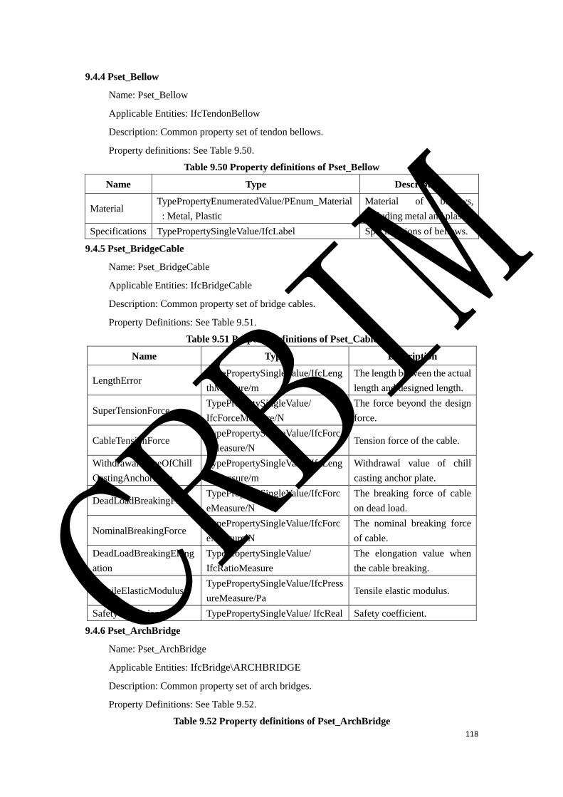
118
9.4.4 Pset_Bellow
Name: Pset_Bellow
Applicable Entities: IfcTendonBellow
Description: Common property set of tendon bellows.
Property definitions: See Table 9.50.
Table 9.50 Property definitions of Pset_Bellow
Name Type Description
Material TypePropertyEnumeratedValue/PEnum_Material
: Metal, Plastic
Material of bellows,
including metal and plastic.
Specifications TypePropertySingleValue/IfcLabel Specifications of bellows.
9.4.5 Pset_BridgeCable
Name: Pset_BridgeCable
Applicable Entities: IfcBridgeCable
Description: Common property set of bridge cables.
Property Definitions: See Table 9.51.
Table 9.51 Property definitions of Pset_Cable
Name Type Description
LengthError TypePropertySingleValue/IfcLeng
thMeasure/m
The length between the actual
length and designed length.
SuperTensionForce TypePropertySingleValue/
IfcForceMeasure/N
The force beyond the design
force.
CableTensionForce TypePropertySingleValue/IfcForc
eMeasure/N Tension force of the cable.
WithdrawalValueOfChill
CastingAnchorPlate
TypePropertySingleValue/IfcLeng
thMeasure/m
Withdrawal value of chill
casting anchor plate.
DeadLoadBreakingForce TypePropertySingleValue/IfcForc
eMeasure/N
The breaking force of cable
on dead load.
NominalBreakingForce TypePropertySingleValue/IfcForc
eMeasure/N
The nominal breaking force
of cable.
DeadLoadBreakingElong
ation
TypePropertySingleValue/
IfcRatioMeasure
The elongation value when
the cable breaking.
TensileElasticModulus TypePropertySingleValue/IfcPress
ureMeasure/Pa Tensile elastic modulus.
SafetyCoefficient TypePropertySingleValue/ IfcReal Safety coefficient.
9.4.6 Pset_ArchBridge
Name: Pset_ArchBridge
Applicable Entities: IfcBridge\ARCHBRIDGE
Description: Common property set of arch bridges.
Property Definitions: See Table 9.52.
Table 9.52 Property definitions of Pset_ArchBridge
CRBIM
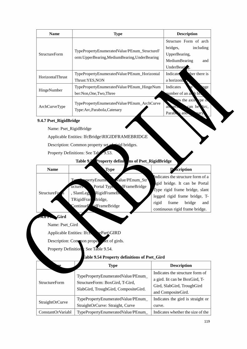
119
Name Type Description
StructureForm TypePropertyEnumeratedValue/PEnum_StructureF
orm:UpperBearing,MediumBearing,UnderBearing
Structure Form of arch
bridges, including
UpperBearing,
MediumBearing and
UnderBearing.
HorizontalThrust TypePropertyEnumeratedValue/PEnum_Horizontal
Thrust:YES,NON
Indicates whether there is
a horizontal force.
HingeNumber TypePropertyEnumeratedValue/PEnum_HingeNum
ber:Non,One,Two,Three
Indicates the hinge
number of an arch bridge.
ArchCurveType TypePropertyEnumeratedValue/PEnum_ArchCurve
Type:Arc,Parabola,Catenary
Indicates the axis type of
an arch. It can be Arc,
Parabola and Catenary.
9.4.7 Pset_RigidBridge
Name: Pset_RigidBridge
Applicable Entities: IfcBridge\RIGIDFRAMEBRIDGE
Description: Common property set of rigid bridges.
Property Definitions: See Table 9.53.
Table 9.53 Property definitions of Pset_RigidBridge
Name Type Description
StructureForm
TypePropertyEnumeratedValue/PEnum_Str
uctureForm: Portal TypeRigidFrameBridge
, SlantLeggedRigidFrameBridge,
TRigidFrameBridge,
ContinueRigidFrameBridge
Indicates the structure form of a
rigid bridge. It can be Portal
Type rigid frame bridge, slant
legged rigid frame bridge, T-
rigid frame bridge and
continuous rigid frame bridge.
9.4.8 Pset_Gird
Name: Pset_Gird
Applicable Entities: IfcBridgePart\GIRD
Description: Common property set of girds.
Property Definitions: See Table 9.54.
Table 9.54 Property definitions of Pset_Gird
Name Type Description
StructureForm
TypePropertyEnumeratedValue/PEnum_
StructureForm: BoxGird, T-Gird,
SlabGird, TroughGird, CompositeGird.
Indicates the structure form of
a gird. Iit can be BoxGird, T-
Gird, SlabGird, TroughGird
and CompositeGird.
StraightOrCurve TypePropertyEnumeratedValue/PEnum_
StraightOrCurve: Straight, Curve
Indicates the gird is straight or
curve.
ConstantOrVariabl TypePropertyEnumeratedValue/PEnum_ Indicates whether the size of the
CRBIM
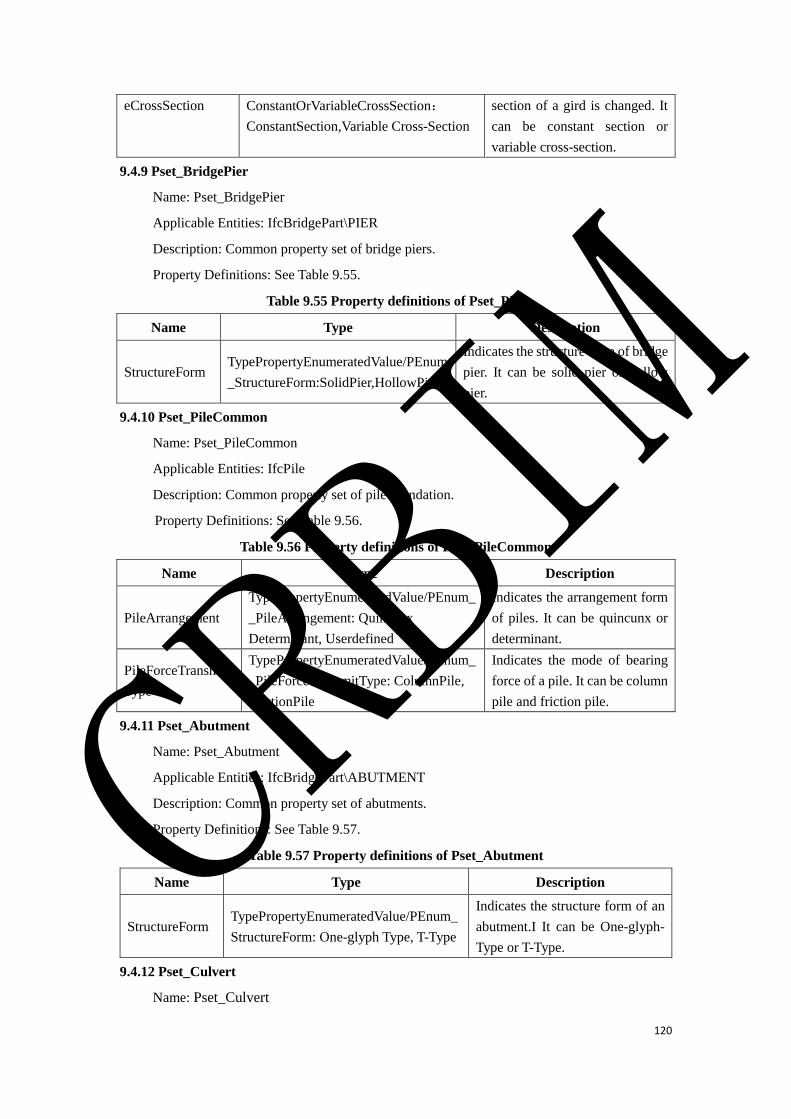
120
eCrossSection ConstantOrVariableCrossSection:
ConstantSection,Variable Cross-Section
section of a gird is changed. It
can be constant section or
variable cross-section.
9.4.9 Pset_BridgePier
Name: Pset_BridgePier
Applicable Entities: IfcBridgePart\PIER
Description: Common property set of bridge piers.
Property Definitions: See Table 9.55.
Table 9.55 Property definitions of Pset_Pier
Name Type Description
StructureForm TypePropertyEnumeratedValue/PEnum
_StructureForm:SolidPier,HollowPier
Indicates the structure form of bridge
pier. It can be solid pier or hollow
pier.
9.4.10 Pset_PileCommon
Name: Pset_PileCommon
Applicable Entities: IfcPile
Description: Common property set of pile foundation.
Property Definitions: See Table 9.56.
Table 9.56 Property definitions of Pset_PileCommon
Name Type Description
PileArrangement
TypePropertyEnumeratedValue/PEnum_
_PileArrangement: Quincunx
Determinant, Userdefined
Indicates the arrangement form
of piles. It can be quincunx or
determinant.
PileForceTransmit
Type
TypePropertyEnumeratedValue/PEnum_
_PileForceTransmitType: ColumnPile,
FrictionPile
Indicates the mode of bearing
force of a pile. It can be column
pile and friction pile.
9.4.11 Pset_Abutment
Name: Pset_Abutment
Applicable Entities: IfcBridgePart\ABUTMENT
Description: Common property set of abutments.
Property Definitions: See Table 9.57.
Table 9.57 Property definitions of Pset_Abutment
Name Type Description
StructureForm TypePropertyEnumeratedValue/PEnum_
StructureForm: One-glyph Type, T-Type
Indicates the structure form of an
abutment.I It can be One-glyph-
Type or T-Type.
9.4.12 Pset_Culvert
Name: Pset_Culvert
CRBIM
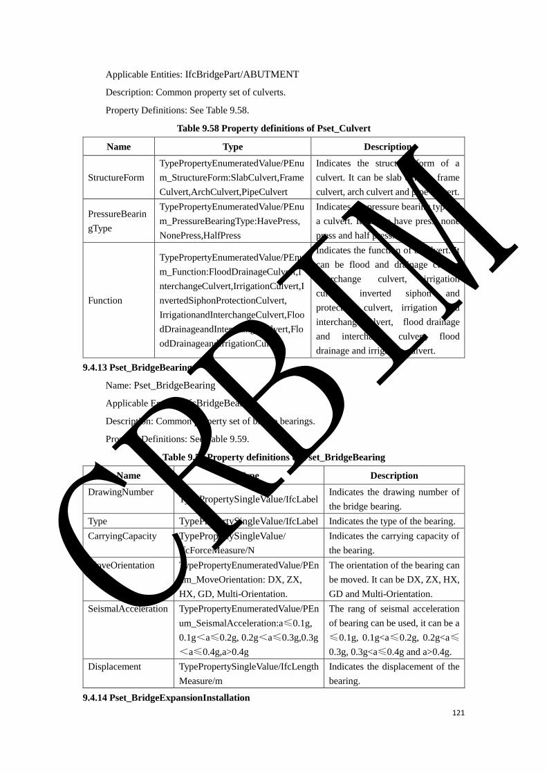
121
Applicable Entities: IfcBridgePart/ABUTMENT
Description: Common property set of culverts.
Property Definitions: See Table 9.58.
Table 9.58 Property definitions of Pset_Culvert
Name Type Description
StructureForm
TypePropertyEnumeratedValue/PEnu
m_StructureForm:SlabCulvert,Frame
Culvert,ArchCulvert,PipeCulvert
Indicates the structure form of a
culvert. It can be slab culvert, frame
culvert, arch culvert and pipe culvert.
PressureBearin
gType
TypePropertyEnumeratedValue/PEnu
m_PressureBearingType:HavePress,
NonePress,HalfPress
Indicates the pressure bearing type of
a culvert. It can be have press, none
press and half press.
Function
TypePropertyEnumeratedValue/PEnu
m_Function:FloodDrainageCulvert,I
nterchangeCulvert,IrrigationCulvert,I
nvertedSiphonProtectionCulvert,
IrrigationandInterchangeCulvert,Floo
dDrainageandInterchangeCulvert,Flo
odDrainageandIrrigationCulvert
Indicates the function of a culvert. It
can be flood and drainage culvert
interchange culvert, irrigation
culvert, inverted siphon and
protection culvert, irrigation and
interchange culvert, flood drainage
and interchange culvert, flood
drainage and irrigation culvert.
9.4.13 Pset_BridgeBearing
Name: Pset_BridgeBearing
Applicable Entities: IfcBridgeBearing
Description: Common property set of bridge bearings.
Property Definitions: See Table 9.59.
Table 9.59 Property definitions of Pset_BridgeBearing
Name Type Description
DrawingNumber TypePropertySingleValue/IfcLabel
Indicates the drawing number of
the bridge bearing.
Type TypePropertySingleValue/IfcLabel Indicates the type of the bearing.
CarryingCapacity TypePropertySingleValue/
IfcForceMeasure/N
Indicates the carrying capacity of
the bearing.
MoveOrientation TypePropertyEnumeratedValue/PEn
um_MoveOrientation: DX, ZX,
HX, GD, Multi-Orientation.
The orientation of the bearing can
be moved. It can be DX, ZX, HX,
GD and Multi-Orientation.
SeismalAcceleration TypePropertyEnumeratedValue/PEn
um_SeismalAcceleration:a≤0.1g,
0.1g<a≤0.2g, 0.2g<a≤0.3g,0.3g
<a≤0.4g,a>0.4g
The rang of seismal acceleration
of bearing can be used, it can be a
≤0.1g, 0.1g<a≤0.2g, 0.2g<a≤
0.3g, 0.3g<a≤0.4g and a>0.4g.
Displacement TypePropertySingleValue/IfcLength
Measure/m
Indicates the displacement of the
bearing.
9.4.14 Pset_BridgeExpansionInstallation
CRBIM
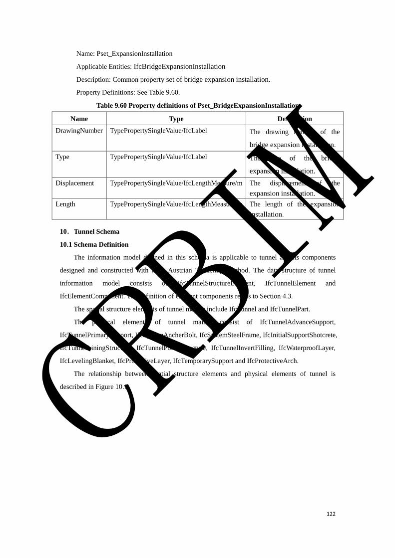
122
Name: Pset_ExpansionInstallation
Applicable Entities: IfcBridgeExpansionInstallation
Description: Common property set of bridge expansion installation.
Property Definitions: See Table 9.60.
Table 9.60 Property definitions of Pset_BridgeExpansionInstallation
Name Type Description
DrawingNumber TypePropertySingleValue/IfcLabel The drawing number of the
bridge expansion installation.
Type TypePropertySingleValue/IfcLabel The type of the bridge
expansion installation.
Displacement TypePropertySingleValue/IfcLengthMeasure/m The displacement of the
expansion installation.
Length TypePropertySingleValue/IfcLengthMeasure/m The length of the expansion
installation.
10.Tunnel Schema
10.1 Schema Definition
The information model defined in this schema is applicable to tunnel and its components
designed and constructed with New Austrian Tunneling Method. The data structure of tunnel
information model consists of IfcTunnelStructureElement, IfcTunnelElement and
IfcElementComponent. The definition of element components refers to Section 4.3.
The spatial structure elements of tunnel mainly include IfcTunnel and IfcTunnelPart.
The physical elements of tunnel mainly consist of IfcTunnelAdvanceSupport,
IfcTunnelPrimarySupport, IfcSystemAncherBolt, IfcSystemSteelFrame, IfcInitialSupportShotcrete,
IfcTunnelLiningStructure, IfcTunnelPortalStructure, IfcTunnelInvertFilling, IfcWaterproofLayer,
IfcLevelingBlanket, IfcProtectiveLayer, IfcTemporarySupport and IfcProtectiveArch.
The relationship between spatial structure elements and physical elements of tunnel is
described in Figure 10.1. CRBIM
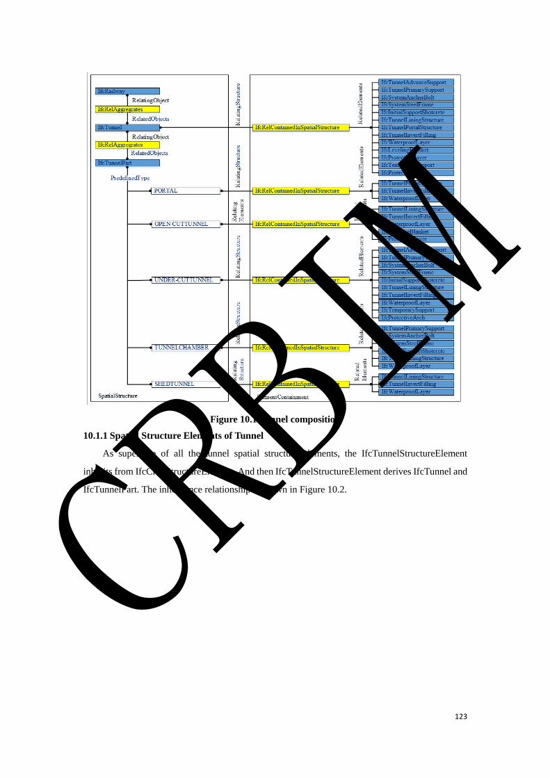
123
Figure 10.1 Tunnel composition
10.1.1 Spatial Structure Elements of Tunnel
As supertype of all the tunnel spatial structure elements, the IfcTunnelStructureElement
inherits from IfcCivilStructureElement. And then IfcTunnelStructureElement derives IfcTunnel and
IfcTunnelPart. The inheritance relationship is shown in Figure 10.2.
CRBIM
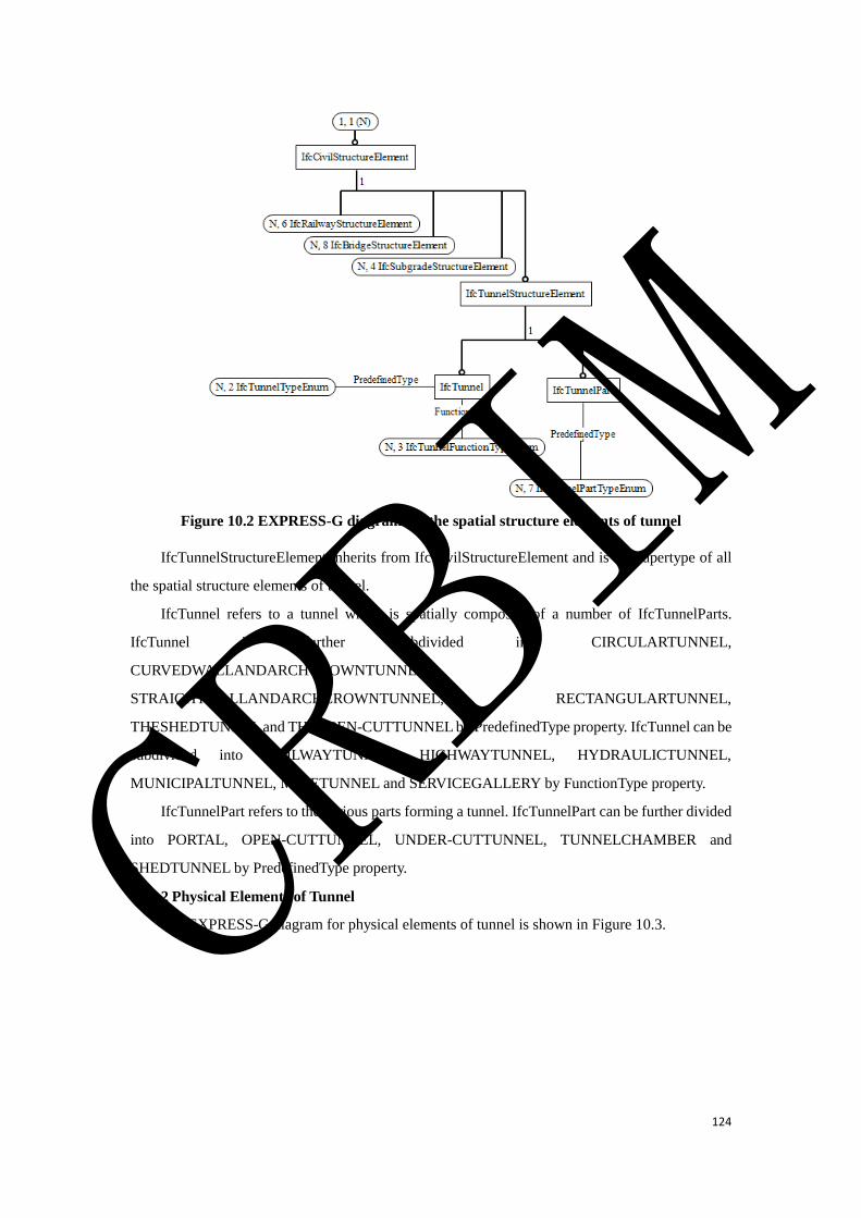
124
Figure 10.2 EXPRESS-G diagram for the spatial structure elements of tunnel
IfcTunnelStructureElement inherits from IfcCivilStructureElement and is the supertype of all
the spatial structure elements of tunnel.
IfcTunnel refers to a tunnel which is spatially composed of a number of IfcTunnelParts.
IfcTunnel is further subdivided into CIRCULARTUNNEL,
CURVEDWALLANDARCHCROWNTUNNEL,
STRAIGHTWALLANDARCHCROWNTUNNEL, RECTANGULARTUNNEL,
THESHEDTUNNEL and THEOPEN-CUTTUNNEL by PredefinedType property. IfcTunnel can be
subdivided into RAILWAYTUNNEL, HIGHWAYTUNNEL, HYDRAULICTUNNEL,
MUNICIPALTUNNEL, MINETUNNEL and SERVICEGALLERY by FunctionType property.
IfcTunnelPart refers to the various parts forming a tunnel. IfcTunnelPart can be further divided
into PORTAL, OPEN-CUTTUNNEL, UNDER-CUTTUNNEL, TUNNELCHAMBER and
SHEDTUNNEL by PredefinedType property.
10.1.2 Physical Elements of Tunnel
The EXPRESS-G diagram for physical elements of tunnel is shown in Figure 10.3. CRBIM
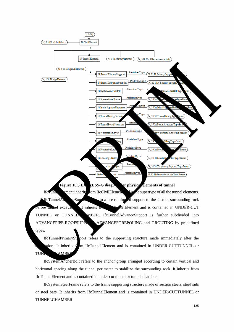
125
Figure 10.3 EXPRESS-G diagram for physical elements of tunnel
IfcTunnelElement inherits from IfcCivilElement and is the supertype of all the tunnel elements.
IfcTunnelAdvanceSupport refers to a pre-reinforced support to the face of surrounding rock
before tunnel excavation. It inherits from IfcTunnelElement and is contained in UNDER-CUT
TUNNEL or TUNNELCHAMBER. IfcTunnelAdvanceSupport is further subdivided into
ADVANCEPIPE-ROOFSUPPORT, ADVANCEFOREPOLING and GROUTING by predefined
types.
IfcTunnelPrimarySupport refers to the supporting structure made immediately after the
excavation. It inherits from IfcTunnelElement and is contained in UNDER-CUTTUNNEL or
TUNNELCHAMBER.
IfcSystemAncherBolt refers to the anchor group arranged according to certain vertical and
horizontal spacing along the tunnel perimeter to stabilize the surrounding rock. It inherits from
IfcTunnelElement and is contained in under-cut tunnel or tunnel chamber.
IfcSystemSteelFrame refers to the frame supporting structure made of section steels, steel rails
or steel bars. It inherits from IfcTunnelElement and is contained in UNDER-CUTTUNNEL or
TUNNELCHAMBER.
CRBIM

126
IfcInitialSupportShotcrete refers to a kind of concrete structure. The concrete mixture is
vertically sprayed on the surface at a higher speed utilizing the compressed air or other power to be
compacted by the continuous impact of cement and aggregate during the spraying process. It inherits
from IfcTunnelElement and is contained in UNDER-CUTTUNNEL or TUNNELCHAMBER.
IfcTunnelLiningStructure refers to the permanent supporting structure of tunnel. It inherits
from IfcTunnelElement and is contained in under-cut tunnel, open-cut tunnel or tunnel chamber.
IfcTunnelLiningStructure is further subdivided into ARCHWALLLINING, INVERTLINING,
SEGMENT and BASESLAB by predefined types.
IfcTunnelPortalStructure refers to door type building to maintain the stability of the front slope
and side slope, to guide drainage slope flow and to decorate the entrance. It inherits from
IfcTunnelElement and is contained in the spatial structure element of tunnel portal.
IfcTunnelPortalStructure is further subdivided into HATSTYLEPORTALSTRUCTURE,
BELLSTYLEPORTALSTRUCTURE, STRAIGHT-CUTPORTALSTRUCTURE,
POURCHAMFEREDPORTALSTRUCTURE, BUFFEREDPORTALSTRUCTURE and
ENDWALLPORTALSTRUCTURE by predefined types.
IfcTunnelInvertFilling refers to the concrete filled in the tunnel invert. It inherits from
IfcTunnelElement and is contained in PORTAL, OPEN-CUTTUNNEL or UNDER-CUTTUNNEL.
IfcWaterproofLayer refers to the waterproof structure attached to the lining, construction joints
and deformation joints. It inherits from IfcTunnelElement and is contained in PORTAL, OPEN-
CUTTUNNEL or UNDER-CUTTUNNEL.
IfcLevelingBlanket refers to the cushion at the bottom of the structure or the leveling layer
before the waterproof layer. It inherits from IfcTunnelElement and is contained in PORTAL or
OPEN-CUTTUNNEL.
IfcProtectiveLayer refers to the protective layer for the tunnel portal or open-cut tunnel before
backfilling. It inherits from IfcTunnelElement and is contained in PORTAL or OPEN-
CUTTUNNEL.
IfcTemporarySupport refers to the temporary support to maintain the stability of the
surrounding rock during the process of tunnel excavation. The support needs to be removed in the
construction process. It inherits from IfcTunnelElement and is contained in UNDER-CUTTUNNEL.
IfcProtectiveArch refers to the protective structure to ensure the safety of tunnel excavation
which is usually chosen when there is no condition for open cutting. It inherits from
IfcTunnelElement and is contained in UNDER-CUTTUNNEL.
10.2 Type Definition
10.2.1 IfcTunnelTypeEnum
This enumeration defines the different predefined types of tunnels that can further specify an
CRBIM

127
IfcTunnel.
Enumerated Item Definitions:
CIRCULARTUNNEL;
CURVEDWALLANDARCHCROWNTUNNEL;
STRAIGHTWALLANDARCHCROWNTUNNEL;
RECTANGULARTUNNEL;
THESHEDTUNNEL;
THEOPEN-CUTTUNNEL;
USERDEFINED;
NOTDEFINED.
EXPRESS Specification:
TYPE IfcTunnelTypeEnum = ENUMERATION OF
(CIRCULARTUNNEL,
CURVEDWALLANDARCHCROWNTUNNEL,
STRAIGHTWALLANDARCHCROWNTUNNEL,
RECTANGULARTUNNEL,
THESHEDTUNNEL,
THEOPEN-CUTTUNNEL,
USERDEFINED,
NOTDEFINED);
END_TYPE;
10.2.2 IfcTunnelFunctionTypeEnum
This enumeration defines the different function types of tunnels.
Enumerated Item Definitions:
RAILWAYTUNNEL;
HIGHWAYTUNNEL;
HYDRAULICTUNNEL;
MUNICIPALTUNNEL;
MINETUNNEL;
SERVICEGALLERY;
USERDEFINED;
NOTDEFINED.
EXPRESS Specification:
TYPE IfcTunnelFunctionTypeEnum = ENUMERATION OF
(RAILWAYTUNNEL,
HIGHWAYTUNNEL,
CRBIM

128
HYDRAULICTUNNEL,
MUNICIPALTUNNEL,
MINETUNNEL,
SERVICEGALLERY,
USERDEFINED,
NOTDEFINED);
END_TYPE;
10.2.3 IfcTunnelPartTypeEnum
This enumeration defines the different composition types of tunnels.
Enumerated Item Definitions:
PORTAL;
OPEN-CUTTUNNEL;
UNDER-CUTTUNNEL;
TUNNELCHAMBER;
SHEDTUNNEL;
USERDEFINED;
NOTDEFINED.
EXPRESS Specification:
TYPE IfcTunnelPartTypeEnum = ENUMERATION OF
(PORTAL,
OPEN-CUTTUNNEL,
UNDER-CUTTUNNEL,
TUNNELCHAMBER,
SHEDTUNNEL,
USERDEFINED,
NOTDEFINED);
END_TYPE;
10.2.4 IfcAdvanceSupportTypeEnum
This enumeration defines the different advance support types of tunnels.
Enumerated Item Definitions:
ADVANCEPIPE-ROOFSUPPORT;
ADVANCEFOREPOLING;
GROUTING;
USERDEFINED;
NOTDEFINED.
EXPRESS Specification:
TYPE IfcAdvanceSupportTypeEnum = ENUMERATION OF
(ADVANCEPIPE-ROOFSUPPORT,
CRBIM

129
ADVANCEFOREPOLING,
GROUTING,
USERDEFINED,
NOTDEFINED);
END_TYPE;
10.2.5 IfcPrimarySupportTypeEnum
This enumeration defines the different primary support types of tunnels.
Enumerated Item Definitions:
USERDEFINED;
NOTDEFINED.
EXPRESS Specification:
TYPE IfcPrimarySupportTypeEnum = ENUMERATION OF
(USERDEFINED,
NOTDEFINED);
END_TYPE;
10.2.6 IfcSystemAncherBoltTypeEnum
This enumeration defines the different ancher bolt types of tunnels.
Enumerated Item Definitions:
USERDEFINED;
NOTDEFINED.
EXPRESS Specification:
TYPE IfcSystemAncherBoltTypeEnum = ENUMERATION OF
(USERDEFINED,
NOTDEFINED);
END_TYPE;
10.2.7 IfcSystemSteelFrameTypeEnum
This enumeration defines the different system steel frame types of tunnels.
Enumerated Item Definitions:
USERDEFINED;
NOTDEFINED.
EXPRESS Specification:
TYPE IfcSystemSteelFrameTypeEnum = ENUMERATION OF
(USERDEFINED,
NOTDEFINED);
END_TYPE;
10.2.8 IfcInitialSupportShotcreteTypeEnum
CRBIM
130
This enumeration defines the different initial support shotcrete types of tunnels.
Enumerated Item Definitions:
USERDEFINED;
NOTDEFINED.
EXPRESS Specification:
TYPE IfcInitialSupportShotcreteTypeEnum = ENUMERATION OF
(USERDEFINED,
NOTDEFINED);
END_TYPE;
10.2.9 IfcTunnelLiningTypeEnum
This enumeration defines the different lining types of tunnels.
Enumerated Item Definitions:
ARCHWALLLINING;
INVERTLINING;
SEGMENT;
BASESLAB;
USERDEFINED;
NOTDEFINED.
EXPRESS Specification:
TYPE IfcTunnelLiningTypeEnum = ENUMERATION OF
(ARCHWALLLINING,
INVERTLINING,
SEGMENT,
BASESLAB,
USERDEFINED,
NOTDEFINED);
END_TYPE;
10.2.10 IfcPortalStructureTypeEnum
This enumeration defines the different portal structure types of tunnels.
Enumerated Item Definitions:
HATSTYLEPORTALSTRUCTURE;
BELLSTYLEPORTALSTRUCTURE;
STRAIGHT-CUTPORTALSTRUCTURE;
POURCHAMFEREDPORTALSTRUCTURE;
BUFFEREDPORTALSTRUCTURE;
ENDWALLPORTALSTRUCTURE;
CRBIM
131
USERDEFINED;
NOTDEFINED.
EXPRESS Specification:
TYPE IfcPortalStructureTypeEnum = ENUMERATION OF
(HATSTYLEPORTALSTRUCTURE,
BELLSTYLEPORTALSTRUCTURE,
STRAIGHT-CUTPORTALSTRUCTURE,
POURCHAMFEREDPORTALSTRUCTURE,
BUFFEREDPORTALSTRUCTURE,
ENDWALLPORTALSTRUCTURE,
USERDEFINED,
NOTDEFINED);
END_TYPE;
10.2.11 IfcInvertFillingTypeEnum
This enumeration defines the different invert filling types of tunnels.
Enumerated Item Definitions:
USERDEFINED;
NOTDEFINED.
EXPRESS Specification:
TYPE IfcInvertFillingTypeEnum = ENUMERATION OF
(USERDEFINED,
NOTDEFINED);
END_TYPE;
10.2.12 IfcWaterproofLayerTypeEnum
This enumeration defines the different waterproof layer types of tunnels.
Enumerated Item Definitions:
USERDEFINED;
NOTDEFINED.
EXPRESS Specification:
TYPE IfcWaterproofLayerTypeEnum = ENUMERATION OF
(USERDEFINED,
NOTDEFINED);
END_TYPE;
10.2.13 IfcLevelingBlanketTypeEnum
This enumeration defines the different leveling blanket types of tunnels.
Enumerated Item Definitions:
USERDEFINED;
CRBIM

132
NOTDEFINED.
EXPRESS Specification:
TYPE IfcLevelingBlanketTypeEnum = ENUMERATION OF
(USERDEFINED,
NOTDEFINED);
END_TYPE;
10.2.14 IfcProtectiveLayerTypeEnum
This enumeration defines the different protective layer types of tunnels.
Enumerated Item Definitions:
USERDEFINED;
NOTDEFINED.
EXPRESS Specification:
TYPE IfcProtectiveLayerTypeEnum = ENUMERATION OF
(USERDEFINED,
NOTDEFINED);
END_TYPE;
10.2.15 IfcProtectiveArchTypeEnum
This enumeration defines the different protective arch types of tunnels.
Enumerated Item Definitions:
USERDEFINED;
NOTDEFINED.
EXPRESS Specification:
TYPE IfcProtectiveArchTypeEnum = ENUMERATION OF
(USERDEFINED,
NOTDEFINED);
END_TYPE;
10.2.16 IfcTemporarySupportTypeEnum
This enumeration defines the different Temporary Support types of tunnels.
Enumerated Item Definitions:
USERDEFINED;
NOTDEFINED.
EXPRESS Specification:
TYPE IfcTemporarySupportTypeEnum = ENUMERATION OF
(USERDEFINED,
NOTDEFINED);
CRBIM
133
END_TYPE;
10.3 Entity Definition
10.3.1 IfcTunnelStructureElement
IfcTunnelStructureElement is the supertype of all the spatial structure elements of tunnel.
EXPRESS Specification:
ENTITY IfcTunnelStructureElement
SUPERTYPE OF (ONEOF (IfcTunnel, IfcTunnelPart))
SUBTYPE OF (IfcCivilStructureElement);
END_ENTITY;
10.3.2 IfcTunnel
IfcTunnel refers to a tunnel which is a part of IfcRailway and is composed of a number of
IfcTunnelPart in space. IfcTunnel is further subdivided into CIRCULARTUNNEL,
CURVEDWALLANDARCHCROWNTUNNEL,
STRAIGHTWALLANDARCHCROWNTUNNEL, RECTANGULARTUNNEL,
THESHEDTUNNEL, THEOPEN-CUTTUNNEL by predefined types and into
RAILWAYTUNNEL, HIGHWAYTUNNEL, HYDRAULICTUNNEL, MUNICIPALTUNNEL,
MINETUNNEL, SERVICEGALLERY by function types.
Table 10.1 IfcTunnel spatial composition
Spatial Composite Description
IfcRailway IfcTunnel is a part of IfcRailway.
Table 10.2 IfcTunnel spatial decomposition
Spatial Parts Description
IfcTunnelPart IfcTunnel is composed of one or more IfcTunnelPart.
Table 10.3 Property sets for IfcTunnel
PredefinedType Name
Pset_TunnelCommon
EXPRESS Specification:
ENTITY IfcTunnel
SUBTYPE OF (IfcTunnelStructureElement);
PredefinedType: IfcTunnelTypeEnum;
FunctionType: IfcTunnelFunctionTypeEnum;
END_ENTITY;
Attribute definitions:
PredefinedType: IfcTunnel is further subdivided into CIRCULARTUNNEL,
CURVEDWALLANDARCHCROWNTUNNEL,
STRAIGHTWALLANDARCHCROWNTUNNEL, RECTANGULARTUNNEL,
THESHEDTUNNEL and THEOPEN-CUTTUNNEL by structural style.
CRBIM
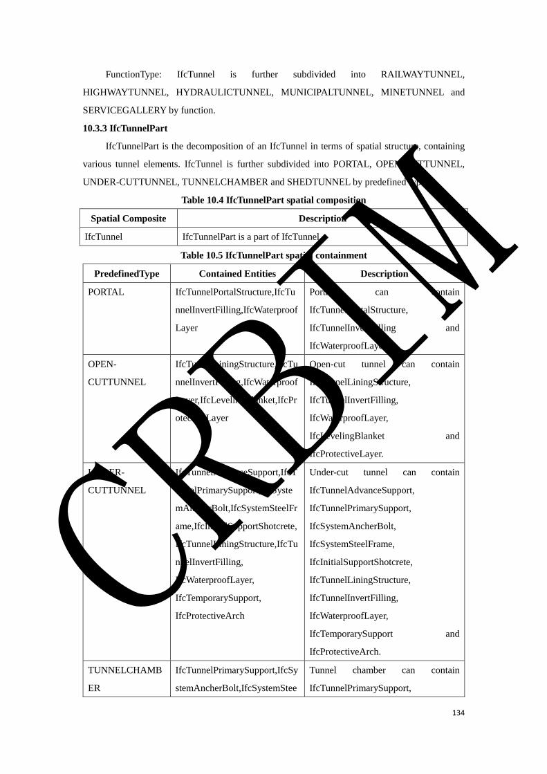
134
FunctionType: IfcTunnel is further subdivided into RAILWAYTUNNEL,
HIGHWAYTUNNEL, HYDRAULICTUNNEL, MUNICIPALTUNNEL, MINETUNNEL and
SERVICEGALLERY by function.
10.3.3 IfcTunnelPart
IfcTunnelPart is the decomposition of an IfcTunnel in terms of spatial structure, containing
various tunnel elements. IfcTunnel is further subdivided into PORTAL, OPEN-CUTTUNNEL,
UNDER-CUTTUNNEL, TUNNELCHAMBER and SHEDTUNNEL by predefined types.
Table 10.4 IfcTunnelPart spatial composition
Spatial Composite Description
IfcTunnel IfcTunnelPart is a part of IfcTunnel.
Table 10.5 IfcTunnelPart spatial containment
PredefinedType Contained Entities Description
PORTAL IfcTunnelPortalStructure,IfcTu
nnelInvertFilling,IfcWaterproof
Layer
Portal can contain
IfcTunnelPortalStructure,
IfcTunnelInvertFilling and
IfcWaterproofLayer.
OPEN-
CUTTUNNEL
IfcTunnelLiningStructure,IfcTu
nnelInvertFilling,IfcWaterproof
Layer,IfcLevelingBlanket,IfcPr
otectiveLayer
Open-cut tunnel can contain
IfcTunnelLiningStructure,
IfcTunnelInvertFilling,
IfcWaterproofLayer,
IfcLevelingBlanket and
IfcProtectiveLayer.
UNDER-
CUTTUNNEL
IfcTunnelAdvanceSupport,IfcT
unnelPrimarySupport,IfcSyste
mAncherBolt,IfcSystemSteelFr
ame,IfcInitialSupportShotcrete,
IfcTunnelLiningStructure,IfcTu
nnelInvertFilling,
IfcWaterproofLayer,
IfcTemporarySupport,
IfcProtectiveArch
Under-cut tunnel can contain
IfcTunnelAdvanceSupport,
IfcTunnelPrimarySupport,
IfcSystemAncherBolt,
IfcSystemSteelFrame,
IfcInitialSupportShotcrete,
IfcTunnelLiningStructure,
IfcTunnelInvertFilling,
IfcWaterproofLayer,
IfcTemporarySupport and
IfcProtectiveArch.
TUNNELCHAMB
ER
IfcTunnelPrimarySupport,IfcSy
stemAncherBolt,IfcSystemStee
Tunnel chamber can contain
IfcTunnelPrimarySupport,
CRBIM
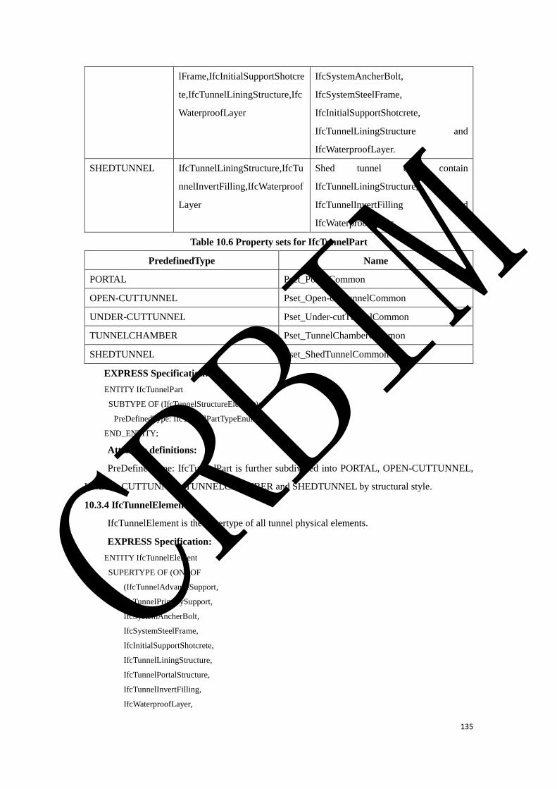
135
lFrame,IfcInitialSupportShotcre
te,IfcTunnelLiningStructure,Ifc
WaterproofLayer
IfcSystemAncherBolt,
IfcSystemSteelFrame,
IfcInitialSupportShotcrete,
IfcTunnelLiningStructure and
IfcWaterproofLayer.
SHEDTUNNEL IfcTunnelLiningStructure,IfcTu
nnelInvertFilling,IfcWaterproof
Layer
Shed tunnel can contain
IfcTunnelLiningStructure,
IfcTunnelInvertFilling and
IfcWaterproofLayer.
Table 10.6 Property sets for IfcTunnelPart
PredefinedType Name
PORTAL Pset_PortalCommon
OPEN-CUTTUNNEL Pset_Open-cutTunnelCommon
UNDER-CUTTUNNEL Pset_Under-cutTunnelCommon
TUNNELCHAMBER Pset_TunnelChamberCommon
SHEDTUNNEL Pset_ShedTunnelCommon
EXPRESS Specification:
ENTITY IfcTunnelPart
SUBTYPE OF (IfcTunnelStructureElement);
PreDefinedType: IfcTunnelPartTypeEnum;
END_ENTITY;
Attribute definitions:
PreDefinedType: IfcTunnelPart is further subdivided into PORTAL, OPEN-CUTTUNNEL,
UNDER-CUTTUNNEL, TUNNELCHAMBER and SHEDTUNNEL by structural style.
10.3.4 IfcTunnelElement
IfcTunnelElement is the supertype of all tunnel physical elements.
EXPRESS Specification:
ENTITY IfcTunnelElement
SUPERTYPE OF (ONEOF
(IfcTunnelAdvanceSupport,
IfcTunnelPrimarySupport,
IfcSystemAncherBolt,
IfcSystemSteelFrame,
IfcInitialSupportShotcrete,
IfcTunnelLiningStructure,
IfcTunnelPortalStructure,
IfcTunnelInvertFilling,
IfcWaterproofLayer,
CRBIM

136
IfcLevelingBlanket,
IfcProtectiveLayer,
IfcTemporarySupport,
IfcProtectiveArch))
SUBTYPE OF (IfcCivilElement);
END_ENTITY;
10.3.5 IfcTunnelAdvanceSupport
IfcTunnelAdvanceSupport refers to a pre-reinforced support to the face of surrounding rock
before tunnel excavation. It inherits from IfcTunnelElement and is contained in UNDER-
CUTTUNNEL or TUNNELCHAMBER. IfcTunnelAdvanceSupport is further subdivided into
ADVANCEPIPE-ROOFSUPPORT, ADVANCEFOREPOLING and GROUTING by predefined
types.
Table 10.7 Property sets for IfcTunnelAdvanceSupport
PredefinedType Name
Pset_TunnelAdvanceSupportCommon
Table 10.8 IfcTunnelAdvanceSupport contained in spatial structure
Spatial Structure Description
IfcTunnelPart/UNDER-CUTTUNNEL IfcTunnelAdvanceSupport should be contained in
UNDER-CUTTUNNEL.
IfcTunnelPart/TUNNELCHAMBER IfcTunnelAdvanceSupport is also contained in
TUNNELCHAMBER.
EXPRESS Specification:
ENTITY IfcTunnelAdvanceSupport
SUBTYPE OF (IfcTunnelElement);
PreDefinedType: IfcTunnelAdvanceSupportTypeEnum;
END_ENTITY;
Attribute definitions:
PreDefinedType: IfcTunnelAdvanceSupport is further subdivided into ADVANCEPIPE-
ROOFSUPPORT, ADVANCEFOREPOLING and GROUTING by structural style.
10.3.6 IfcTunnelPrimarySupport
IfcTunnelPrimarySupport refers to the supporting structure made immediately after the
excavation. It inherits from IfcTunnelElement and is contained in UNDER-CUTTUNNEL or
TUNNELCHAMBER which are the predefined types of IfcTunnelPart.
Table 10.9 Property sets for IfcTunnelPrimarySupport
PredefinedType Name
Pset_TunnelPrimarySupportCommon
Table 10.10 IfcTunnelPrimarySupport contained in spatial structure
CRBIM
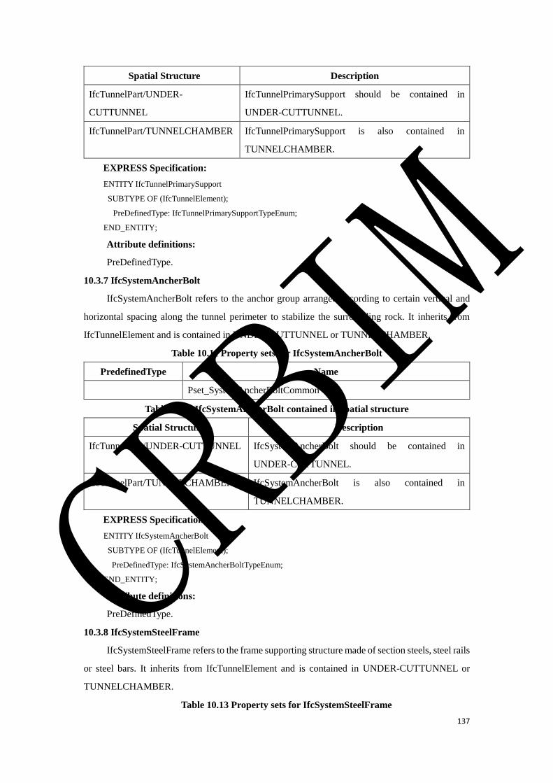
137
Spatial Structure Description
IfcTunnelPart/UNDER-
CUTTUNNEL
IfcTunnelPrimarySupport should be contained in
UNDER-CUTTUNNEL.
IfcTunnelPart/TUNNELCHAMBER IfcTunnelPrimarySupport is also contained in
TUNNELCHAMBER.
EXPRESS Specification:
ENTITY IfcTunnelPrimarySupport
SUBTYPE OF (IfcTunnelElement);
PreDefinedType: IfcTunnelPrimarySupportTypeEnum;
END_ENTITY;
Attribute definitions:
PreDefinedType.
10.3.7 IfcSystemAncherBolt
IfcSystemAncherBolt refers to the anchor group arranged according to certain vertical and
horizontal spacing along the tunnel perimeter to stabilize the surrounding rock. It inherits from
IfcTunnelElement and is contained in UNDER-CUTTUNNEL or TUNNELCHAMBER.
Table 10.11 Property sets for IfcSystemAncherBolt
PredefinedType Name
Pset_SystemAncherBoltCommon
Table 10.12 IfcSystemAncherBolt contained in spatial structure
Spatial Structure Description
IfcTunnelPart/UNDER-CUTTUNNEL IfcSystemAncherBolt should be contained in
UNDER-CUTTUNNEL.
IfcTunnelPart/TUNNELCHAMBER IfcSystemAncherBolt is also contained in
TUNNELCHAMBER.
EXPRESS Specification:
ENTITY IfcSystemAncherBolt
SUBTYPE OF (IfcTunnelElement);
PreDefinedType: IfcSystemAncherBoltTypeEnum;
END_ENTITY;
Attribute definitions:
PreDefinedType.
10.3.8 IfcSystemSteelFrame
IfcSystemSteelFrame refers to the frame supporting structure made of section steels, steel rails
or steel bars. It inherits from IfcTunnelElement and is contained in UNDER-CUTTUNNEL or
TUNNELCHAMBER.
Table 10.13 Property sets for IfcSystemSteelFrame
CRBIM

138
PredefinedType Name
Pset_SystemSteelFrameCommon
Table 10.14 IfcSystemSteelFrame contained in spatial structure
Spatial Structure Description
IfcTunnelPart/UNDER-CUTTUNNEL IfcSystemSteelFrame should be contained in UNDER-
CUTTUNNEL.
IfcTunnelPart/TUNNELCHAMBER IfcSystemSteelFrame is also contained in
TUNNELCHAMBER.
EXPRESS Specification:
ENTITY IfcSystemSteelFrame
SUBTYPE OF (IfcTunnelElement);
PreDefinedType: IfcSystemSteelFrameTypeEnum;
END_ENTITY;
Attribute definitions:
PreDefinedType.
10.3.9 IfcInitialSupportShotcrete
IfcInitialSupportShotcrete refers to a kind of concrete structure. The concrete mixture is
vertically sprayed on the surface at a higher speed utilizing the compressed air or other power to be
compacted by the continuous impact of cement and aggregate during the spraying process. It inherits
from IfcTunnelElement and is contained in UNDER-CUTTUNNEL or TUNNELCHAMBER.
Table 10.15 Property sets for IfcInitialSupportShotcrete
PredefinedType Name
Pset_InitialSupportShotcreteCommon
Table 10.16 IfcInitialSupportShotcrete contained in spatial structure
Spatial Structure Description
IfcTunnelPart/UNDER-CUTTUNNEL IfcInitialSupportShotcrete should be contained in
UNDER-CUTTUNNEL.
IfcTunnelPart/TUNNELCHAMBER IfcInitialSupportShotcrete is also contained in
TUNNELCHAMBER.
EXPRESS Specification:
ENTITY IfcInitialSupportShotcrete
SUBTYPE OF (IfcTunnelElement);
PreDefinedType: IfcInitialSupportShotcreteTypeEnum;
END_ENTITY;
Attribute definitions:
PreDefinedType.
10.3.10 IfcTunnelLiningStructure
CRBIM

139
IfcTunnelLiningStructure refers to the permanent supporting structure of tunnel. It inherits
from IfcTunnelElement and is contained in UNDER-CUTTUNNEL, OPEN-CUTTUNNEL or
TUNNELCHAMBER. IfcTunnelLiningStructure is further subdivided into ARCHWALLLINING,
INVERTLINING, SEGMENT and BASESLAB by PredefinedType property.
Table 10.17 Property sets for IfcTunnelLiningStructure
PredefinedType Name
Pset_TunnelLiningStructureCommon
Table 10.18 IfcTunnelLiningStructure contained in spatial structure
Spatial Structure Description
IfcTunnelPart/UNDER-CUTTUNNEL IfcTunnelLiningStructure should be contained in
UNDER-CUTTUNNEL.
IfcTunnelPart/OPEN-CUTTUNNEL IfcTunnelLiningStructure is also contained in OPEN-
CUTTUNNEL.
IfcTunnelPart/TUNNELCHAMBER IfcTunnelLiningStructure is also contained in
TUNNELCHAMBER.
EXPRESS Specification:
ENTITY IfcTunnelLiningStructure
SUBTYPE OF (IfcTunnelElement);
PreDefinedType: IfcTunnelLiningStructureTypeEnum;
END_ENTITY;
Attribute definitions:
PreDefinedType: IfcTunnelLiningStructure is further subdivided into ARCHWALLLINING,
INVERTLINING, SEGMENT and BASESLAB by structural style.
10.3.11 IfcTunnelPortalStructure
IfcTunnelPortalStructure refers to door type building to maintain the stability of the front slope
and side slope, to guide drainage slope flow and to decorate the entrance. It inherits from
IfcTunnelElement and is contained in the spatial structure element of tunnel portal.
IfcTunnelPortalStructure is further subdivided into HATSTYLEPORTALSTRUCTURE,
BELLSTYLEPORTALSTRUCTURE, STRAIGHT-CUTPORTALSTRUCTURE,
POURCHAMFEREDPORTALSTRUCTURE, BUFFEREDPORTALSTRUCTURE, and
ENDWALLPORTALSTRUCTURE by predefined types.
Table 10.19 IfcTunnelPortalStructure contained in spatial structure
Spatial Structure Description
IfcTunnelPart/PORTAL IfcTunnelPortalStructure should be contained in PORTAL.
EXPRESS Specification:
ENTITY IfcTunnelPortalStructure
CRBIM
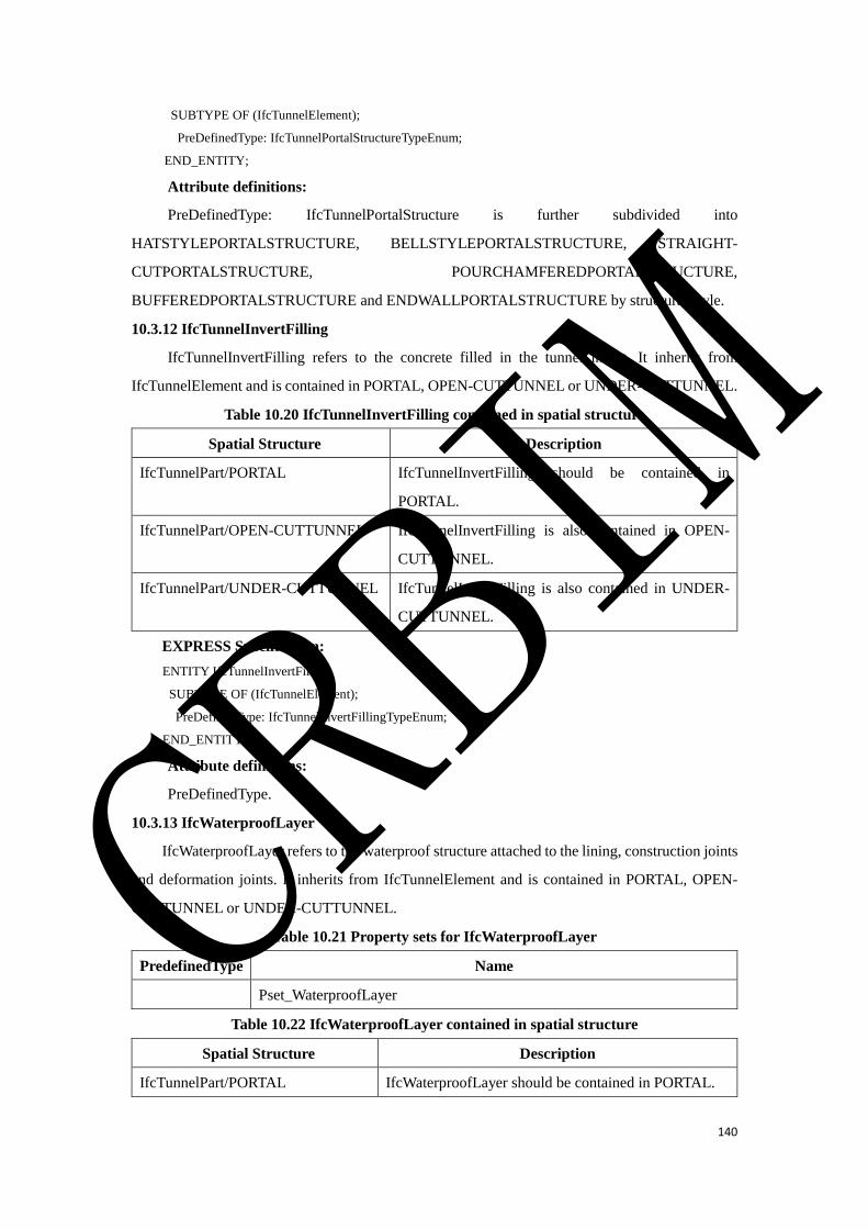
140
SUBTYPE OF (IfcTunnelElement);
PreDefinedType: IfcTunnelPortalStructureTypeEnum;
END_ENTITY;
Attribute definitions:
PreDefinedType: IfcTunnelPortalStructure is further subdivided into
HATSTYLEPORTALSTRUCTURE, BELLSTYLEPORTALSTRUCTURE, STRAIGHT-
CUTPORTALSTRUCTURE, POURCHAMFEREDPORTALSTRUCTURE,
BUFFEREDPORTALSTRUCTURE and ENDWALLPORTALSTRUCTURE by structural style.
10.3.12 IfcTunnelInvertFilling
IfcTunnelInvertFilling refers to the concrete filled in the tunnel invert. It inherits from
IfcTunnelElement and is contained in PORTAL, OPEN-CUTTUNNEL or UNDER-CUTTUNNEL.
Table 10.20 IfcTunnelInvertFilling contained in spatial structure
Spatial Structure Description
IfcTunnelPart/PORTAL IfcTunnelInvertFilling should be contained in
PORTAL.
IfcTunnelPart/OPEN-CUTTUNNEL IfcTunnelInvertFilling is also contained in OPEN-
CUTTUNNEL.
IfcTunnelPart/UNDER-CUTTUNNEL IfcTunnelInvertFilling is also contained in UNDER-
CUTTUNNEL.
EXPRESS Specification:
ENTITY IfcTunnelInvertFilling
SUBTYPE OF (IfcTunnelElement);
PreDefinedType: IfcTunnelInvertFillingTypeEnum;
END_ENTITY;
Attribute definitions:
PreDefinedType.
10.3.13 IfcWaterproofLayer
IfcWaterproofLayer refers to the waterproof structure attached to the lining, construction joints
and deformation joints. It inherits from IfcTunnelElement and is contained in PORTAL, OPEN-
CUTTUNNEL or UNDER-CUTTUNNEL.
Table 10.21 Property sets for IfcWaterproofLayer
PredefinedType Name
Pset_WaterproofLayer
Table 10.22 IfcWaterproofLayer contained in spatial structure
Spatial Structure Description
IfcTunnelPart/PORTAL IfcWaterproofLayer should be contained in PORTAL.
CRBIM

141
IfcTunnelPart/OPEN-CUTTUNNEL IfcWaterproofLayer is also contained in OPEN-
CUTTUNNEL.
IfcTunnelPart/UNDER-
CUTTUNNEL
IfcWaterproofLayer is also contained in UNDER-
CUTTUNNEL.
EXPRESS Specification:
ENTITY IfcWaterproofLayer
SUBTYPE OF (IfcTunnelElement);
PreDefinedType: IfcWaterproofLayerTypeEnum;
END_ENTITY;
Attribute definitions:
PreDefinedType.
10.3.14 IfcLevelingBlanket
IfcLevelingBlanket refers to the cushion at the bottom of the structure or the leveling layer
before the waterproof layer. It inherits from IfcTunnelElement and is contained in PORTAL or
OPEN-CUTTUNNEL.
Table 10.23 Property sets for IfcLevelingBlanket
PredefinedType Name
Pset_LevelingBlanketCommon
Table 10.24 IfcLevelingBlanket contained in spatial structure
Spatial Structure Description
IfcTunnelPart/PORTAL IfcLevelingBlanket should be contained in PORTAL.
IfcTunnelPart/OPEN-CUTTUNNEL IfcLevelingBlanket is also contained in OPEN-
CUTTUNNEL.
EXPRESS Specification:
ENTITY IfcLevelingBlanket
SUBTYPE OF (IfcTunnelElement);
PreDefinedType: IfcLevelingBlanketTypeEnum;
END_ENTITY;
Attribute definitions:
PreDefinedType.
10.3.15 IfcProtectiveLayer
IfcProtectiveLayer refers to the protective layer for the tunnel portal or open-cut tunnel before
backfilling. It inherits from IfcTunnelElement and is contained in PORTAL or OPEN-
CUTTUNNEL.
Table 10.25 Property sets for IfcProtectiveLayer
PredefinedType Name
Pset_IfcProtectiveLayerCommon
CRBIM
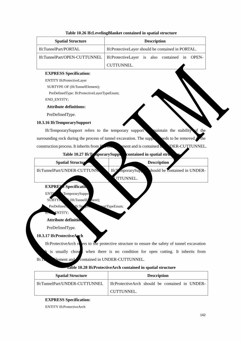
142
Table 10.26 IfcLevelingBlanket contained in spatial structure
Spatial Structure Description
IfcTunnelPart/PORTAL IfcProtectiveLayer should be contained in PORTAL.
IfcTunnelPart/OPEN-CUTTUNNEL IfcProtectiveLayer is also contained in OPEN-
CUTTUNNEL.
EXPRESS Specification:
ENTITY IfcProtectiveLayer
SUBTYPE OF (IfcTunnelElement);
PreDefinedType: IfcProtectiveLayerTypeEnum;
END_ENTITY;
Attribute definitions:
PreDefinedType.
10.3.16 IfcTemporarySupport
IfcTemporarySupport refers to the temporary support to maintain the stability of the
surrounding rock during the process of tunnel excavation. The support needs to be removed in the
construction process. It inherits from IfcTunnelElement and is contained in UNDER-CUTTUNNEL.
Table 10.27 IfcTemporarySupport contained in spatial structure
Spatial Structure Description
IfcTunnelPart/UNDER-CUTTUNNEL IfcTemporarySupport should be contained in UNDER-
CUTTUNNEL.
EXPRESS Specification:
ENTITY IfcTemporarySupport
SUBTYPE OF (IfcTunnelElement);
PreDefinedType: IfcTemporarySupportTypeEnum;
END_ENTITY;
Attribute definitions:
PreDefinedType.
10.3.17 IfcProtectiveArch
IfcProtectiveArch refers to the protective structure to ensure the safety of tunnel excavation
which is usually chosen when there is no condition for open cutting. It inherits from
IfcTunnelElement and is contained in UNDER-CUTTUNNEL.
Table 10.28 IfcProtectiveArch contained in spatial structure
Spatial Structure Description
IfcTunnelPart/UNDER-CUTTUNNEL IfcProtectiveArch should be contained in UNDER-
CUTTUNNEL.
EXPRESS Specification:
ENTITY IfcProtectiveArch
CRBIM
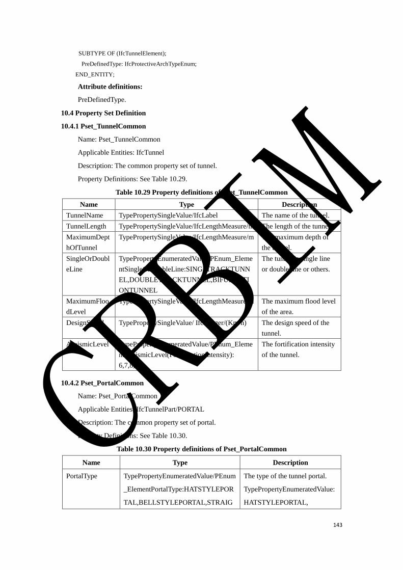
143
SUBTYPE OF (IfcTunnelElement);
PreDefinedType: IfcProtectiveArchTypeEnum;
END_ENTITY;
Attribute definitions:
PreDefinedType.
10.4 Property Set Definition
10.4.1 Pset_TunnelCommon
Name: Pset_TunnelCommon
Applicable Entities: IfcTunnel
Description: The common property set of tunnel.
Property Definitions: See Table 10.29.
Table 10.29 Property definitions of Pset_TunnelCommon
Name Type Description
TunnelName TypePropertySingleValue/IfcLabel The name of the tunnel.
TunnelLength TypePropertySingleValue/IfcLengthMeasure/m The length of the tunnel.
MaximumDept
hOfTunnel
TypePropertySingleValue/IfcLengthMeasure/m The maximum depth of
the tunnel.
SingleOrDoubl
eLine
TypePropertyEnumeratedValue/PEnum_Eleme
ntSingleOrDoubleLine:SINGLTRACKTUNN
EL,DOUBLETRACKTUNNEL,BIFURCATI
ONTUNNEL
The tunnel is single line
or double line or others.
MaximumFloo
dLevel
TypePropertySingleValue/IfcLengthMeasure/m The maximum flood level
of the area.
DesignSpeed TypePropertySingleValue/ IfcInteger/(Km/h) The design speed of the
tunnel.
AseismicLevel TypePropertyEnumeratedValue/PEnum_Eleme
ntAseismicLevel(FortificationIntensity):
6,7,8,9
The fortification intensity
of the tunnel.
10.4.2 Pset_PortalCommon
Name: Pset_PortalCommon
Applicable Entities: IfcTunnelPart/PORTAL
Description: The common property set of portal.
Property Definitions: See Table 10.30.
Table 10.30 Property definitions of Pset_PortalCommon
Name Type Description
PortalType TypePropertyEnumeratedValue/PEnum
_ElementPortalType:HATSTYLEPOR
TAL,BELLSTYLEPORTAL,STRAIG
The type of the tunnel portal.
TypePropertyEnumeratedValue:
HATSTYLEPORTAL,
CRBIM
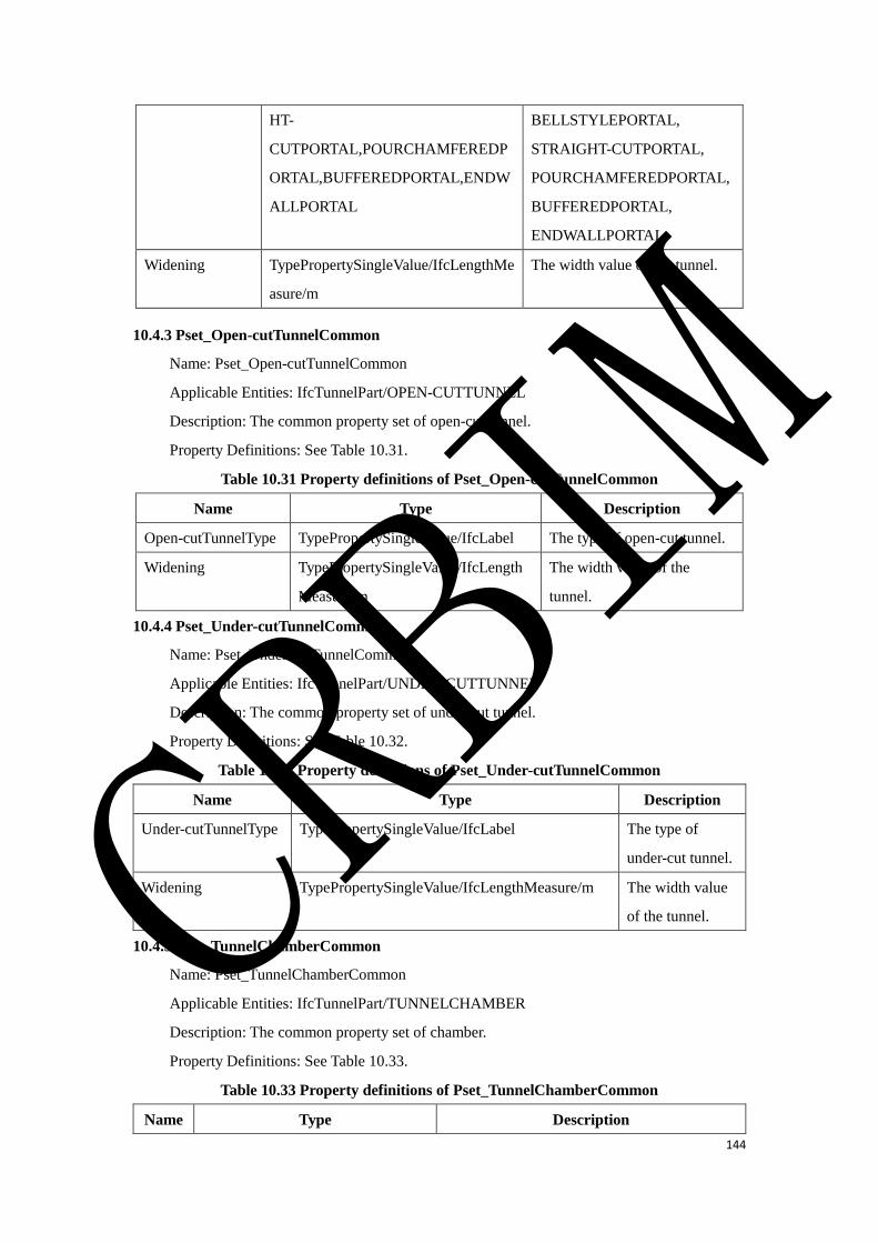
144
HT-
CUTPORTAL,POURCHAMFEREDP
ORTAL,BUFFEREDPORTAL,ENDW
ALLPORTAL
BELLSTYLEPORTAL,
STRAIGHT-CUTPORTAL,
POURCHAMFEREDPORTAL,
BUFFEREDPORTAL,
ENDWALLPORTAL.
Widening TypePropertySingleValue/IfcLengthMe
asure/m
The width value of the tunnel.
10.4.3 Pset_Open-cutTunnelCommon
Name: Pset_Open-cutTunnelCommon
Applicable Entities: IfcTunnelPart/OPEN-CUTTUNNEL
Description: The common property set of open-cut tunnel.
Property Definitions: See Table 10.31.
Table 10.31 Property definitions of Pset_Open-cutTunnelCommon
Name Type Description
Open-cutTunnelType TypePropertySingleValue/IfcLabel The type of open-cut tunnel.
Widening TypePropertySingleValue/IfcLength
Measure/m
The width value of the
tunnel.
10.4.4 Pset_Under-cutTunnelCommon
Name: Pset_Under-cutTunnelCommon
Applicable Entities: IfcTunnelPart/UNDER-CUTTUNNEL
Description: The common property set of under-cut tunnel.
Property Definitions: See Table 10.32.
Table 10.32 Property definitions of Pset_Under-cutTunnelCommon
Name Type Description
Under-cutTunnelType TypePropertySingleValue/IfcLabel The type of
under-cut tunnel.
Widening TypePropertySingleValue/IfcLengthMeasure/m The width value
of the tunnel.
10.4.5 Pset_TunnelChamberCommon
Name: Pset_TunnelChamberCommon
Applicable Entities: IfcTunnelPart/TUNNELCHAMBER
Description: The common property set of chamber.
Property Definitions: See Table 10.33.
Table 10.33 Property definitions of Pset_TunnelChamberCommon
Name Type Description
CRBIM
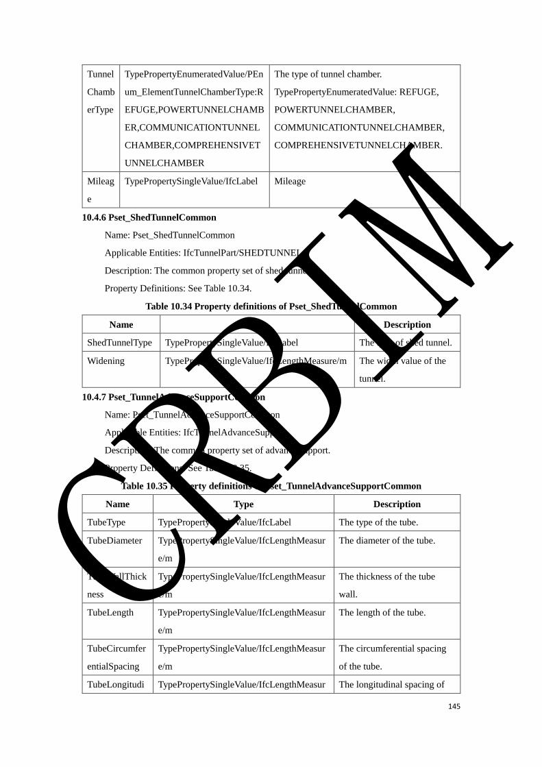
145
Tunnel
Chamb
erType
TypePropertyEnumeratedValue/PEn
um_ElementTunnelChamberType:R
EFUGE,POWERTUNNELCHAMB
ER,COMMUNICATIONTUNNEL
CHAMBER,COMPREHENSIVET
UNNELCHAMBER
The type of tunnel chamber.
TypePropertyEnumeratedValue: REFUGE,
POWERTUNNELCHAMBER,
COMMUNICATIONTUNNELCHAMBER,
COMPREHENSIVETUNNELCHAMBER.
Mileag
e
TypePropertySingleValue/IfcLabel Mileage
10.4.6 Pset_ShedTunnelCommon
Name: Pset_ShedTunnelCommon
Applicable Entities: IfcTunnelPart/SHEDTUNNEL
Description: The common property set of shed tunnel.
Property Definitions: See Table 10.34.
Table 10.34 Property definitions of Pset_ShedTunnelCommon
Name Type Description
ShedTunnelType TypePropertySingleValue/IfcLabel The type of shed tunnel.
Widening TypePropertySingleValue/IfcLengthMeasure/m The width value of the
tunnel.
10.4.7 Pset_TunnelAdvanceSupportCommon
Name: Pset_TunnelAdvanceSupportCommon
Applicable Entities: IfcTunnelAdvanceSupport
Description: The common property set of advance support.
Property Definitions: See Table 10.35.
Table 10.35 Property definitions of Pset_TunnelAdvanceSupportCommon
Name Type Description
TubeType TypePropertySingleValue/IfcLabel The type of the tube.
TubeDiameter TypePropertySingleValue/IfcLengthMeasur
e/m
The diameter of the tube.
TubeWallThick
ness
TypePropertySingleValue/IfcLengthMeasur
e/m
The thickness of the tube
wall.
TubeLength TypePropertySingleValue/IfcLengthMeasur
e/m
The length of the tube.
TubeCircumfer
entialSpacing
TypePropertySingleValue/IfcLengthMeasur
e/m
The circumferential spacing
of the tube.
TubeLongitudi TypePropertySingleValue/IfcLengthMeasur The longitudinal spacing of
CRBIM
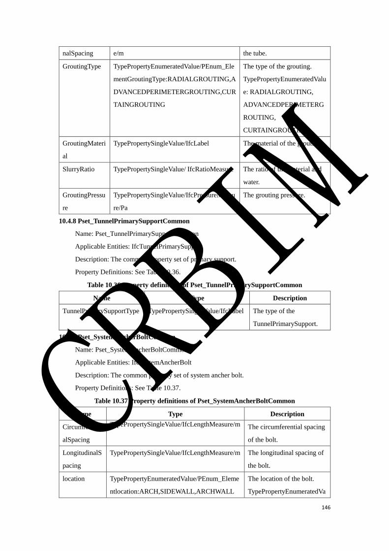
146
nalSpacing e/m the tube.
GroutingType TypePropertyEnumeratedValue/PEnum_Ele
mentGroutingType:RADIALGROUTING,A
DVANCEDPERIMETERGROUTING,CUR
TAINGROUTING
The type of the grouting.
TypePropertyEnumeratedValu
e: RADIALGROUTING,
ADVANCEDPERIMETERG
ROUTING,
CURTAINGROUTING.
GroutingMateri
al
TypePropertySingleValue/IfcLabel The material of the grouting.
SlurryRatio TypePropertySingleValue/ IfcRatioMeasure The ratio of the material and
water.
GroutingPressu
re
TypePropertySingleValue/IfcPressureMeasu
re/Pa
The grouting pressure.
10.4.8 Pset_TunnelPrimarySupportCommon
Name: Pset_TunnelPrimarySupportCommon
Applicable Entities: IfcTunnelPrimarySupport
Description: The common property set of primary support.
Property Definitions: See Table 10.36.
Table 10.36 Property definitions of Pset_TunnelPrimarySupportCommon
Name Type Description
TunnelPrimarySupportType TypePropertySingleValue/IfcLabel The type of the
TunnelPrimarySupport.
10.4.9 Pset_SystemAncherBoltCommon
Name: Pset_SystemAncherBoltCommon
Applicable Entities: IfcSystemAncherBolt
Description: The common property set of system ancher bolt.
Property Definitions: See Table 10.37.
Table 10.37 Property definitions of Pset_SystemAncherBoltCommon
Name Type Description
Circumferenti
alSpacing
TypePropertySingleValue/IfcLengthMeasure/m The circumferential spacing
of the bolt.
LongitudinalS
pacing
TypePropertySingleValue/IfcLengthMeasure/m The longitudinal spacing of
the bolt.
location TypePropertyEnumeratedValue/PEnum_Eleme
ntlocation:ARCH,SIDEWALL,ARCHWALL
The location of the bolt.
TypePropertyEnumeratedVa
CRBIM
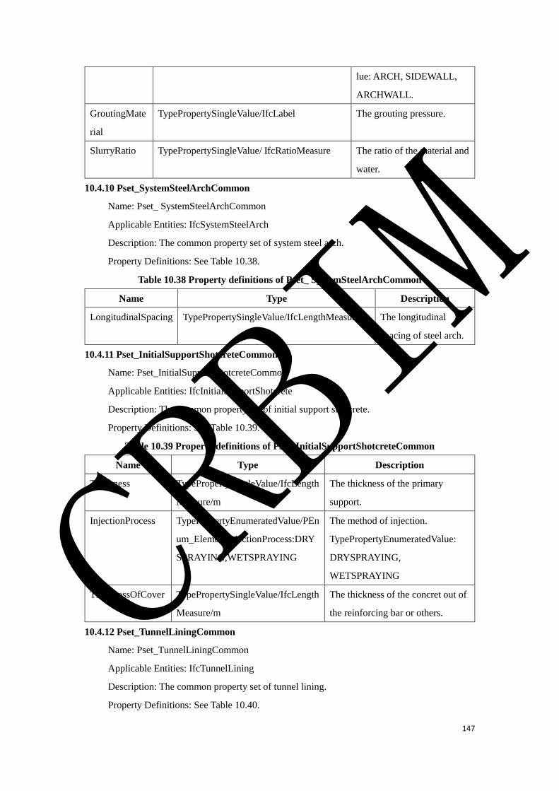
147
lue: ARCH, SIDEWALL,
ARCHWALL.
GroutingMate
rial
TypePropertySingleValue/IfcLabel The grouting pressure.
SlurryRatio TypePropertySingleValue/ IfcRatioMeasure The ratio of the material and
water.
10.4.10 Pset_SystemSteelArchCommon
Name: Pset_ SystemSteelArchCommon
Applicable Entities: IfcSystemSteelArch
Description: The common property set of system steel arch.
Property Definitions: See Table 10.38.
Table 10.38 Property definitions of Pset_ SystemSteelArchCommon
Name Type Description
LongitudinalSpacing TypePropertySingleValue/IfcLengthMeasure/m The longitudinal
spacing of steel arch.
10.4.11 Pset_InitialSupportShotcreteCommon
Name: Pset_InitialSupportShotcreteCommon
Applicable Entities: IfcInitialSupportShotcrete
Description: The common property set of initial support shotcrete.
Property Definitions: See Table 10.39.
Table 10.39 Property definitions of Pset_InitialSupportShotcreteCommon
Name Type Description
Thickness TypePropertySingleValue/IfcLength
Measure/m
The thickness of the primary
support.
InjectionProcess TypePropertyEnumeratedValue/PEn
um_ElementInjectionProcess:DRY
SPRAYING,WETSPRAYING
The method of injection.
TypePropertyEnumeratedValue:
DRYSPRAYING,
WETSPRAYING
ThicknessOfCover TypePropertySingleValue/IfcLength
Measure/m
The thickness of the concret out of
the reinforcing bar or others.
10.4.12 Pset_TunnelLiningCommon
Name: Pset_TunnelLiningCommon
Applicable Entities: IfcTunnelLining
Description: The common property set of tunnel lining.
Property Definitions: See Table 10.40.
CRBIM
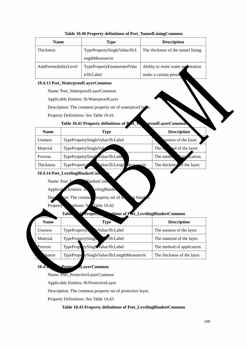
148
Table 10.40 Property definitions of Pset_TunnelLiningCommon
Name Type Description
Thickness TypePropertySingleValue/IfcL
engthMeasure/m
The thickness of the tunnel lining.
AntiPermeabilityLevel TypePropertyEnumeratedValu
e/IfcLabel
Ability to resist water penetration
under a certain pressure.
10.4.13 Pset_WaterproofLayerCommon
Name: Pset_WaterproofLayerCommon
Applicable Entities: IfcWaterproofLayer
Description: The common property set of waterproof layer.
Property Definitions: See Table 10.41.
Table 10.41 Property definitions of Pset_WaterproofLayerCommon
Name Type Description
Useness TypePropertySingleValue/IfcLabel The useness of the layer.
Material TypePropertySingleValue/IfcLabel The material of the layer.
Process TypePropertySingleValue/IfcLabel The method of application.
Thickness TypePropertySingleValue/IfcLengthMeasure/m The thickness of the layer.
10.4.14 Pset_LevelingBlanketCommon
Name: Pset_LevelingBlanketCommon
Applicable Entities: IfcLevelingBlanket
Description: The common property set of leveling blanket.
Property Definitions: See Table 10.42.
Table 10.42 Property definitions of Pset_LevelingBlanketCommon
Name Type Description
Useness TypePropertySingleValue/IfcLabel The useness of the layer.
Material TypePropertySingleValue/IfcLabel The material of the layer.
Process TypePropertySingleValue/IfcLabel The method of application.
Thickness TypePropertySingleValue/IfcLengthMeasure/m The thickness of the layer.
10.4.15 Pset_ProtectiveLayerCommon
Name: Pset_ProtectiveLayerCommon
Applicable Entities: IfcProtectiveLayer
Description: The common property set of protective layer.
Property Definitions: See Table 10.43.
Table 10.43 Property definitions of Pset_LevelingBlanketCommon
CRBIM
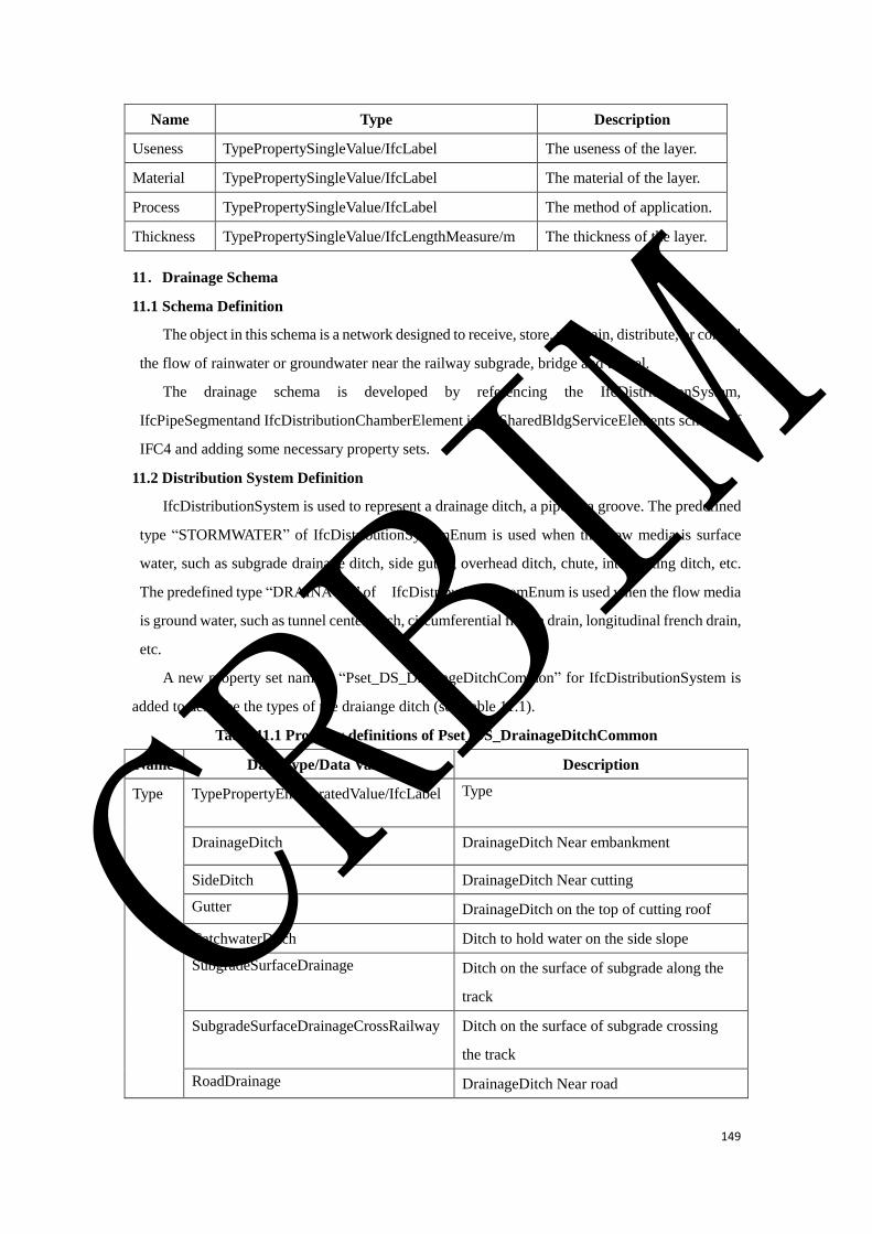
149
Name Type Description
Useness TypePropertySingleValue/IfcLabel The useness of the layer.
Material TypePropertySingleValue/IfcLabel The material of the layer.
Process TypePropertySingleValue/IfcLabel The method of application.
Thickness TypePropertySingleValue/IfcLengthMeasure/m The thickness of the layer.
11.Drainage Schema
11.1 Schema Definition
The object in this schema is a network designed to receive, store, maintain, distribute, or control
the flow of rainwater or groundwater near the railway subgrade, bridge and tunnel.
The drainage schema is developed by referencing the IfcDistributionSystem,
IfcPipeSegmentand IfcDistributionChamberElement in IfcSharedBldgServiceElements schema of
IFC4 and adding some necessary property sets.
11.2 Distribution System Definition
IfcDistributionSystem is used to represent a drainage ditch, a pipe or a groove. The predefined
type “STORMWATER” of IfcDistributionSystemEnum is used when the flow media is surface
water, such as subgrade drainage ditch, side gutter, overhead ditch, chute, intercepting ditch, etc.
The predefined type “DRAINAGE” of IfcDistributionSystemEnum is used when the flow media
is ground water, such as tunnel center ditch, circumferential french drain, longitudinal french drain,
etc.
A new property set named “Pset_DS_DrainageDitchCommon” for IfcDistributionSystem is
added to describe the types of the draiange ditch (see Table 11.1).
Table 11.1 Property definitions of Pset_DS_DrainageDitchCommon
Name Data Type/Data Value Description
Type TypePropertyEnumeratedValue/IfcLabel Type
DrainageDitch DrainageDitch Near embankment
SideDitch DrainageDitch Near cutting
Gutter DrainageDitch on the top of cutting roof
CatchwaterDitch Ditch to hold water on the side slope
SubgradeSurfaceDrainage Ditch on the surface of subgrade along the
track
SubgradeSurfaceDrainageCrossRailway Ditch on the surface of subgrade crossing
the track
RoadDrainage DrainageDitch Near road
CRBIM
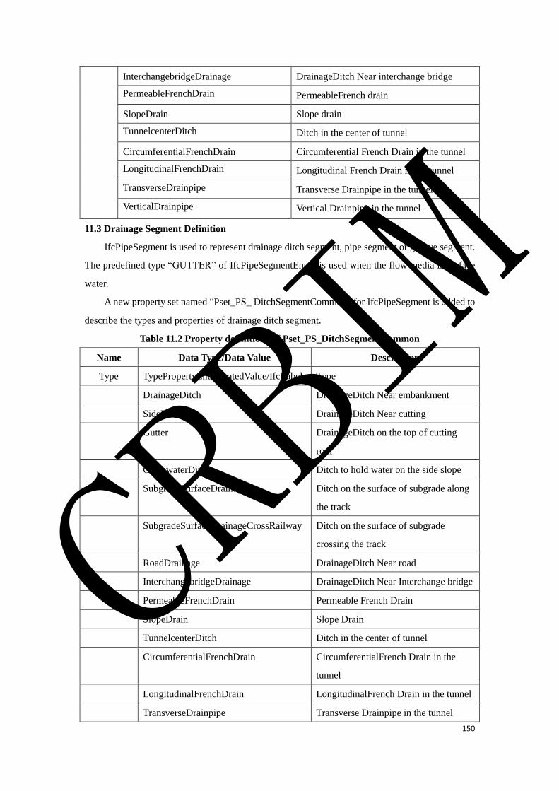
150
InterchangebridgeDrainage DrainageDitch Near interchange bridge
PermeableFrenchDrain PermeableFrench drain
SlopeDrain Slope drain
TunnelcenterDitch Ditch in the center of tunnel
CircumferentialFrenchDrain Circumferential French Drain in the tunnel
LongitudinalFrenchDrain Longitudinal French Drain in the tunnel
TransverseDrainpipe Transverse Drainpipe in the tunnel
VerticalDrainpipe Vertical Drainpipe in the tunnel
11.3 Drainage Segment Definition
IfcPipeSegment is used to represent drainage ditch segment, pipe segment or groove segment.
The predefined type “GUTTER” of IfcPipeSegmentEnum is used when the flow media is surface
water.
A new property set named “Pset_PS_ DitchSegmentCommon” for IfcPipeSegment is added to
describe the types and properties of drainage ditch segment.
Table 11.2 Property definitions of Pset_PS_DitchSegmentCommon
Name Data Type/Data Value Description
Type TypePropertyEnumeratedValue/IfcLabel Type
DrainageDitch DrainageDitch Near embankment
SideDitch DrainageDitch Near cutting
Gutter DrainageDitch on the top of cutting
roof
CatchwaterDitch Ditch to hold water on the side slope
SubgradeSurfaceDrainage Ditch on the surface of subgrade along
the track
SubgradeSurfaceDrainageCrossRailway Ditch on the surface of subgrade
crossing the track
RoadDrainage DrainageDitch Near road
InterchangebridgeDrainage DrainageDitch Near Interchange bridge
PermeableFrenchDrain Permeable French Drain
SlopeDrain Slope Drain
TunnelcenterDitch Ditch in the center of tunnel
CircumferentialFrenchDrain CircumferentialFrench Drain in the
tunnel
LongitudinalFrenchDrain LongitudinalFrench Drain in the tunnel
TransverseDrainpipe Transverse Drainpipe in the tunnel
CRBIM
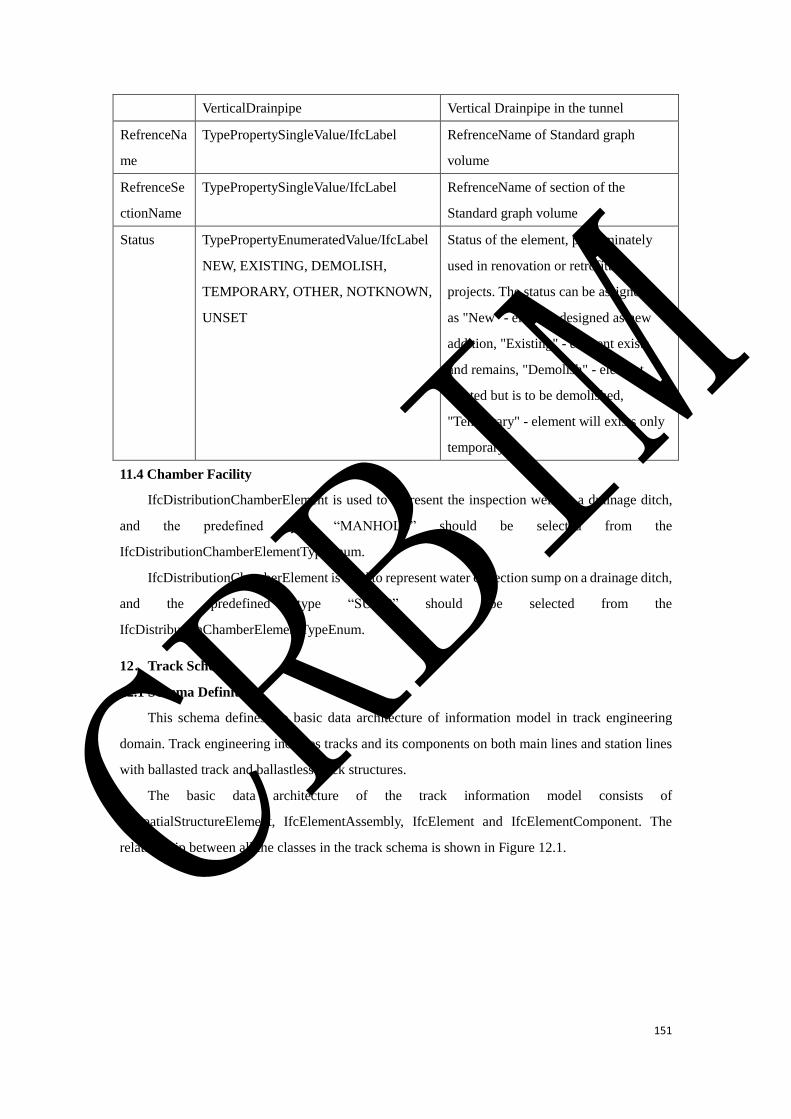
151
VerticalDrainpipe Vertical Drainpipe in the tunnel
RefrenceNa
me
TypePropertySingleValue/IfcLabel RefrenceName of Standard graph
volume
RefrenceSe
ctionName
TypePropertySingleValue/IfcLabel RefrenceName of section of the
Standard graph volume
Status TypePropertyEnumeratedValue/IfcLabel
NEW, EXISTING, DEMOLISH,
TEMPORARY, OTHER, NOTKNOWN,
UNSET
Status of the element, predominately
used in renovation or retrofitting
projects. The status can be assigned to
as "New" - element designed as new
addition, "Existing" - element exists
and remains, "Demolish" - element
existed but is to be demolished,
"Temporary" - element will exists only
temporary
11.4 Chamber Facility
IfcDistributionChamberElement is used to represent the inspection well on a drainage ditch,
and the predefined type “MANHOLE” should be selected from the
IfcDistributionChamberElementTypeEnum.
IfcDistributionChamberElement is used to represent water collection sump on a drainage ditch,
and the predefined type “SUMP” should be selected from the
IfcDistributionChamberElementTypeEnum.
12.Track Schema
12.1 Schema Definition
This schema defines the basic data architecture of information model in track engineering
domain. Track engineering includes tracks and its components on both main lines and station lines
with ballasted track and ballastless track structures.
The basic data architecture of the track information model consists of
IfcSpatialStructureElement, IfcElementAssembly, IfcElement and IfcElementComponent. The
relationship between all the classes in the track schema is shown in Figure 12.1. CRBIM
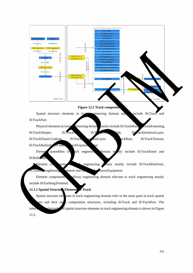
152
Figure 12.1 Track composition
Spatial structure elements in track engineering domain mainly include IfcTrack and
IfcTrackPart.
Physical elements in track engineering domain mainly include IfcTrackRail, IfcTrackFastening,
IfcTrackSleeper, IfcTrackSlab, IfcTrackConcreteSlab, IfcTrackIsolationLayer,
IfcTrackElasticCushion, IfcTrackAdjustmentLayer, IfcTrackBase, IfcTrackTurnout,
IfcTrackBallastLayer and IfcTrackExpansionJoint.
Element assemblies in track engineering domain mainly include IfcTrackPanel and
IfcBallastBed.
Element components in track engineering domain mainly include IfcTrackRailJoint,
IfcTrackStrengtheningEquipment and IfcTrackAccessoryEquipment.
Element components in railway engineering domain relevant to track engineering mainly
include IfcEarthingTerminal.
12.1.1 Spatial Structure Elements of Track
Spatial structure elements in track engineering domain refer to the main parts in track spatial
structures and their main composition structures, including IfcTrack and IfcTrackPart. The
inheritance relationship of spatial structure elements in track engineering domain is shown in Figure
12.2. CRBIM
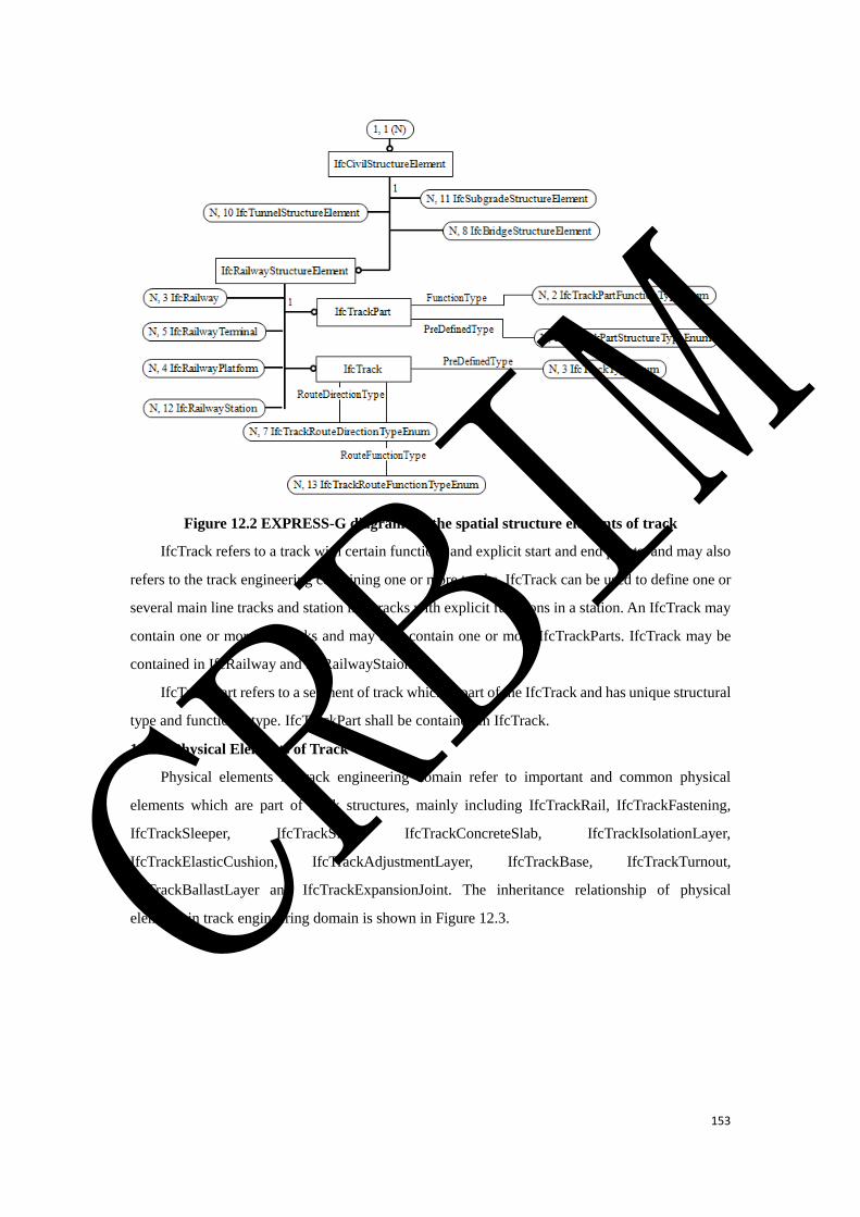
153
Figure 12.2 EXPRESS-G diagram for the spatial structure elements of track
IfcTrack refers to a track with certain functions and explicit start and end points, and may also
refers to the track engineering containing one or more tracks. IfcTrack can be used to define one or
several main line tracks and station line tracks with explicit functions in a station. An IfcTrack may
contain one or more IfcTracks and may also contain one or more IfcTrackParts. IfcTrack may be
contained in IfcRailway and IfcRailwayStaion.
IfcTrackPart refers to a segment of track which is part of the IfcTrack and has unique structural
type and functional type. IfcTrackPart shall be contained in IfcTrack.
12.1.2 Physical Elements of Track
Physical elements in track engineering domain refer to important and common physical
elements which are part of track structures, mainly including IfcTrackRail, IfcTrackFastening,
IfcTrackSleeper, IfcTrackSlab, IfcTrackConcreteSlab, IfcTrackIsolationLayer,
IfcTrackElasticCushion, IfcTrackAdjustmentLayer, IfcTrackBase, IfcTrackTurnout,
IfcTrackBallastLayer and IfcTrackExpansionJoint. The inheritance relationship of physical
elements in track engineering domain is shown in Figure 12.3. CRBIM
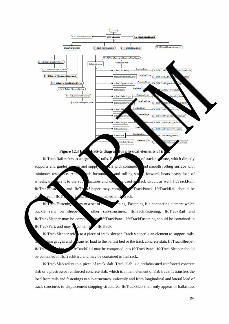
154
Figure 12.3 EXPRESS-G diagram for physical elements of track
IfcTrackRail refers to a segment of rails. Rail is a main part of track structure, which directly
supports and guides wheels and supplys wheels with continuous and smooth rolling surface with
minimum resistance. And it leads locomotives and rolling stocks forward, bears heavy load of
wheels, transfers it to the sub-structures and could be used as track circuit as well. IfcTrackRail,
IfcTrackFastening and IfcTrackSleeper may comprise IfcTrackPanel. IfcTrackRail should be
contained in IfcTrackPart, and may be contained in IfcTrack.
IfcTrackFastening refers to a set of track fastening. Fastening is a connecting element which
buckle rails on sleepers or other sub-structures. IfcTrackFastening, IfcTrackRail and
IfcTrackSleeper may be composed into IfcTrackPanel. IfcTrackFastening should be contained in
IfcTrackPart, and may be contained in IfcTrack.
IfcTrackSleeper refers to a piece of track sleeper. Track sleeper is an element to support rails,
to maintain gauges and to transfer load to the ballast bed or the track concrete slab. IfcTrackSleeper,
IfcTrackFastening and IfcTrackRail may be composed into IfcTrackPanel. IfcTrackSleeper should
be contained in IfcTrackPart, and may be contained in IfcTrack.
IfcTrackSlab refers to a piece of track slab. Track slab is a prefabricated reinforced concrete
slab or a prestressed reinforced concrete slab, which is a main element of slab track. It transfers the
load from rails and fastenings to sub-structures uniformly and from longitudinal and lateral load of
track structures to displacement-stopping structures. IfcTrackSlab shall only appear in ballastless
CRBIM

155
track structures. IfcTrackSlab should be contained in IfcTrackPart, and may be contained in IfcTrack.
IfcTrackConcreteSlab refers to a piece of track concrete slab. Track concrete slab is an integral
reinforced concrete layer cast in-situ, in which bi-block sleepers, concrete turnout sleepers or other
sleepers are embedded. IfcTrackConcreteSlab shall only appear in ballastless track structures.
IfcTrackConcreteSlab should be contained in IfcTrackPart, and may be contained in IfcTrack.
IfcTrackIsolationLayer refers to a piece of track isolation layer. Isolation layer is a structure
layer placed on the top surface of track bases. It may implement functions of damage repair of track
superstructure under special circumstances and coordinate temperature deformation.
IfcTrackIsolationLayer shall only appear in ballastless track structures. IfcTrackIsolationLayer
should be contained in IfcTrackPart, and may be contained in IfcTrack.
IfcTrackElasticCushion refers to a piece of track elastic cushion. Elastic cushion is a kind of
layer set on trough sides of a concrete base, which is used for mitigating the impact of longitudinal
and lateral load on track structures. IfcTrackElasticCushion shall only appear in ballastless track
structures. IfcTrackElasticCushion should be contained in IfcTrackPart, and may be contained in
IfcTrack.
IfcTrackAdjustmentLayer refers to a piece of adjustment layer. Adjustment layer is a concrete
layer or a mortar layer cast or paved in-situ, which is used for supporting track slabs or track concrete
slabs. IfcTrackAdjustmentLayer shall only appear in ballastless track structures.
IfcTrackAdjustmentLayer should be contained in IfcTrackPart, and may be contained in IfcTrack.
IfcTrackBase refers to a piece of concrete base. Concrete base is a kind of reinforced
foundation cast in-situ, which is used for supporting track slabs or track concrete slabs. IfcTrackBase
shall only appear in ballastless track structures. IfcTrackBase should be contained in IfcTrackPart,
and may be contained in IfcTrack.
IfcTrackTurnout refers to a set of turnouts. Turnout is a facility to transform one track into two
or more tracks. IfcTrackTurnout should be contained in all the types of IfcTrackPart except the type
of WITHNOTURNOUT and may be contained in IfcTrack.
IfcTrackBallastLayer refers to one ballast layer. Ballast layer is a structure layer which
comprises different kinds of granular materials with different particle size grading, such as crushed
stones, pebbles, sands, slags and so on. It can directly support or fix sleepers, transfer loads and play
a role in drainage system, etc. One or more IfcTrackBallastLayer may be composed into an
IfcBallastBed. IfcTrackBallastLayer shall only appear in ballasted track structures.
IfcTrackBallastLayer should be contained in IfcTrackPart, and may be contained in IfcTrack.
IfcTrackExpansionJoint refers to a set of rail expansion joint. Rail expansion joint is a facility
to adjust the expansion of rails. IfcTrackExpansionJoint should be contained in IfcTrackPart, and
may be contained in IfcTrack.
CRBIM
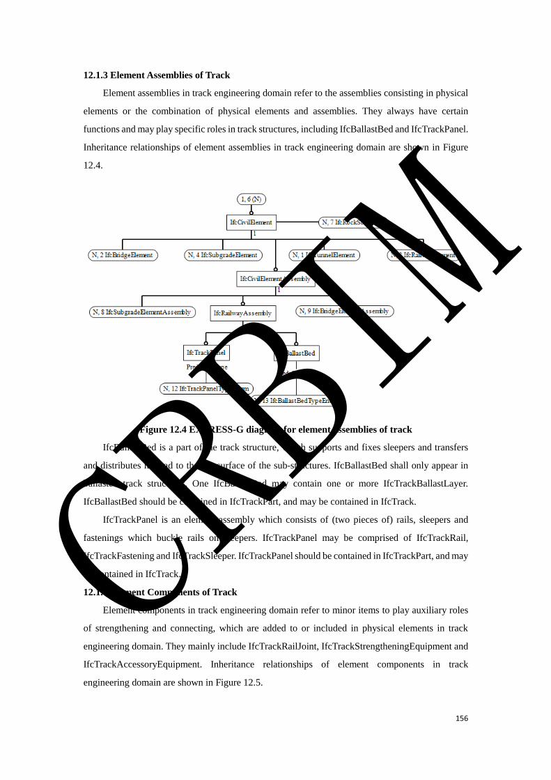
156
12.1.3 Element Assemblies of Track
Element assemblies in track engineering domain refer to the assemblies consisting in physical
elements or the combination of physical elements and assemblies. They always have certain
functions and may play specific roles in track structures, including IfcBallastBed and IfcTrackPanel.
Inheritance relationships of element assemblies in track engineering domain are shown in Figure
12.4.
Figure 12.4 EXPRESS-G diagram for element assemblies of track
IfcBallastBed is a part of the track structure, which supports and fixes sleepers and transfers
and distributes its load to the top surface of the sub-structures. IfcBallastBed shall only appear in
ballasted track structures. One IfcBallastBed may contain one or more IfcTrackBallastLayer.
IfcBallastBed should be contained in IfcTrackPart, and may be contained in IfcTrack.
IfcTrackPanel is an element assembly which consists of (two pieces of) rails, sleepers and
fastenings which buckle rails on sleepers. IfcTrackPanel may be comprised of IfcTrackRail,
IfcTrackFastening and IfcTrackSleeper. IfcTrackPanel should be contained in IfcTrackPart, and may
be contained in IfcTrack.
12.1.4 Element Components of Track
Element components in track engineering domain refer to minor items to play auxiliary roles
of strengthening and connecting, which are added to or included in physical elements in track
engineering domain. They mainly include IfcTrackRailJoint, IfcTrackStrengtheningEquipment and
IfcTrackAccessoryEquipment. Inheritance relationships of element components in track
engineering domain are shown in Figure 12.5.
CRBIM
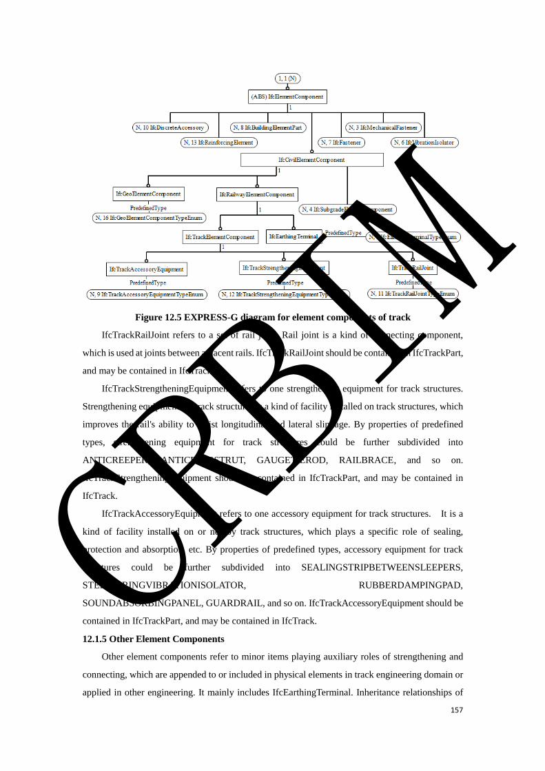
157
Figure 12.5 EXPRESS-G diagram for element components of track
IfcTrackRailJoint refers to a set of rail joint. Rail joint is a kind of connecting component,
which is used at joints between adjacent rails. IfcTrackRailJoint should be contained in IfcTrackPart,
and may be contained in IfcTrack.
IfcTrackStrengtheningEquipment refers to one strengthening equipment for track structures.
Strengthening equipment for track structures is a kind of facility installed on track structures, which
improves the rail's ability to resist longitudinal and lateral slippage. By properties of predefined
types, strengthening equipment for track structures could be further subdivided into
ANTICREEPER, ANTICREEPSTRUT, GAUGETIEROD, RAILBRACE, and so on.
IfcTrackStrengtheningEquipment should be contained in IfcTrackPart, and may be contained in
IfcTrack.
IfcTrackAccessoryEquipment refers to one accessory equipment for track structures. It is a
kind of facility installed on or nearby track structures, which plays a specific role of sealing,
protection and absorption, etc. By properties of predefined types, accessory equipment for track
structures could be further subdivided into SEALINGSTRIPBETWEENSLEEPERS,
STEELSPRINGVIBRATIONISOLATOR, RUBBERDAMPINGPAD,
SOUNDABSORBINGPANEL, GUARDRAIL, and so on. IfcTrackAccessoryEquipment should be
contained in IfcTrackPart, and may be contained in IfcTrack.
12.1.5 Other Element Components
Other element components refer to minor items playing auxiliary roles of strengthening and
connecting, which are appended to or included in physical elements in track engineering domain or
applied in other engineering. It mainly includes IfcEarthingTerminal. Inheritance relationships of
CRBIM
158
other element components are shown in Figure 12.5.
IfcEarthingTerminal refers to a terminal connected to a grounding object. IfcEarthingTerminal
should be contained in IfcTrackPart, and may be contained in IfcTrack.
12.2 Type Definition
12.2.1 IfcTrackTypeEnum
IfcTrackTypeEnum is an enumeration of track types, which defines the different functional
types of track.
Enumerated Item Definitions:
MAINTRACK;
CONNECTINGLINE;
RUNNINGTRACKFORMULTIPLEUNIT;
UNTWININGLINE;
RECEIVINGDEPATURETRACK;
SWITCHINGLEAD;
CATCHSIDING;
FREIGHTTRACK;
CLASSIFICATIONTRACK;
LOCOMOTIVERUNNINGTRACK;
REFUGESIDING;
ROUNDABOUTLINE;
ROLLINGFORBIDDENTRACK;
ROLLINGTRACK;
LOCOMOTIVESERVICETRACK;
LOCOMOTIVEHOLDTRACK;
STORAGETRACK;
REPAIRSIDING;
USERDEFINED;
NOTDEFINED.
EXPRESS Specification:
TYPE IfcTrackTypeEnum = ENUMERATION OF
(MAINTRACK
,CONNECTINGLINE
,RUNNINGTRACKFORMULTIPLEUNIT
,UNTWININGLINE
,RECEIVINGDEPATURETRACK
,SWITCHINGLEAD
CRBIM

159
,CATCHSIDING
,FREIGHTTRACK
,CLASSIFICATIONTRACK
,LOCOMOTIVERUNNINGTRACK
,REFUGESIDING
,ROUNDABOUTLINE
,ROLLINGFORBIDDENTRACK
,ROLLINGTRACK
,LOCOMOTIVESERVICETRACK
,LOCOMOTIVEHOLDTRACK
,STORAGETRACK
,REPAIRSIDING
,USERDEFINED
,NOTDEFINED
);
END_TYPE;
12.2.2 IfcTrackRouteDirectionTypeEnum
IfcTrackRouteDirectionTypeEnum is an enumeration of directional types of track route,
which defines the different directional types of track route.
Enumerated Item Definitions:
UPDIRECTIONROUTE;
DOWNDIRECTIONROUTE;
EITHERDIRECTIONALROUTE.
EXPRESS Specification:
TYPE IfcTrackRouteDirectionTypeEnum= ENUMERATION OF
(UPDIRECTIONROUTE
,DOWNDIRECTIONROUTE
, EITHERDIRECTIONALROUTE
);
END_TYPE;
12.2.3 IfcTrackRouteFunctionTypeEnum
IfcTrackRouteFunctionTypeEnum is an enumeration of functional types of track route, which
defines the different functional types of track route.
Enumerated Item Definitions:
PASSENGERLINE;
FREIGHTLINE;
PASSENGERFREIGHTLINE;
ENTERDEPOTLINEFORLOCOMOTIVE;
EXITDEPOTLINEFORLOCOMOTIVE.
CRBIM
160
EXPRESS Specification:
TYPE IfcTrackRouteFunctionTypeEnum= ENUMERATION OF
(PASSENGERLINE
, FREIGHTLINE
, PASSENGERFREIGHTLINE
, ENTERDEPOTLINEFORLOCOMOTIVE
, EXITDEPOTLINEFORLOCOMOTIVE
);
END_TYPE;
12.2.4 IfcTrackPartStructureTypeEnum
IfcTrackPartStructureTypeEnum is an enumeration of the structural types of track part, which
defines the different structural types of track part foundation.
Enumerated Item Definitions:
ONSUBGRADE;
ONBRIDGE;
INTUNNEL;
TRANSITIONSECTION;
ONSPECIALFOUNDATION;
USERDEFINED;
NOTDEFINED.
EXPRESS Specification:
TYPE IfcTrackPartStructureTypeEnum= ENUMERATION OF
(ONSUBGRADE
, ONBRIDGE
, INTUNNEL
, TRANSITIONSECTION
, ONSPECIALFOUNDATION
, USERDEFINED
, NOTDEFINED
);
END_TYPE;
12.2.5 IfcTrackPartFunctionTypeEnum
IfcTrackPartFunctionTypeEnum is an enumeration of functional types of track part, which
defines the different functional types of track part.
Enumerated Item Definitions:
WITHTURNOUT;
WITHNOTURNOUT.
CRBIM
161
EXPRESS Specification:
TYPE IfcTrackPartFunctionTypeEnum= ENUMERATION OF
(WITHTURNOUT
, WITHNOTURNOUT
);
END_TYPE;
12.2.6 IfcTrackRailTypeEnum
IfcTrackRailTypeEnum is an enumeration of rail types, which defines the different types of
rails.
Enumerated Item Definitions:
HEAVYDUTYTRACK;
LIGHTDUTYTRACK;
USERDEFINED;
NOTDEFINED.
EXPRESS Specification:
TYPE IfcTrackRailTypeEnum= ENUMERATION OF
(HEAVYDUTYTRACK
, LIGHTDUTYTRACK
, USERDEFINED
, NOTDEFINED
);
END_TYPE;
12.2.7 IfcTrackFasteningElasticityTypeEnum
IfcTrackFasteningElasticityTypeEnum is an enumeration of fastening types, which defines the
different types of fastening clips.
Enumerated Item Definitions:
ELASTICRAILFASTENING;
RIGIDRAILFASTENING.
EXPRESS Specification:
TYPE IfcTrackFasteningElasticityTypeEnum= ENUMERATION OF
(ELASTICRAILFASTENING
, RIGIDRAILFASTENING
);
END_TYPE;
12.2.8 IfcTrackFasteningStructureTypeEnum
IfcTrackFasteningStructureTypeEnum is an enumeration of structural types of fastening
CRBIM

162
components, which defines the different structural types of fastening components.
Enumerated Item Definitions:
SEPARATEDRAILFASTENING;
SEMISEPARATEDRAILFASTENING;
NONSEPARATEDRAILFASTENING.
EXPRESS Specification:
TYPE IfcTrackFasteningStructureTypeEnum= ENUMERATION OF
(SEPARATEDRAILFASTENING
, SEMISEPARATEDRAILFASTENING
, NONSEPARATEDRAILFASTENING
);
END_TYPE;
12.2.9 IfcTrackSleeperTypeEnum
IfcTrackSleeperTypeEnum is an enumeration of sleeper types, which defines the different
structural types of sleepers.
Enumerated Item Definitions:
CONCRETESLEEPER;
WOODENSLEEPER;
BROADCONCRETESLEEPER;
CONCRETELASTICSLEEPER;
CAPACITIVESLEEPER;
ELECTRICINSULATEDSLEEPER;
BIBLOCKSLEEPER;
SUPPORTINGBLOCK;
USERDEFINED;
NOTDEFINED.
EXPRESS Specification:
TYPE IfcTrackSleeperTypeEnum= ENUMERATION OF
( CONCRETESLEEPER
, WOODENSLEEPER
, BROADCONCRETESLEEPER
, CONCRETELASTICSLEEPER
, CAPACITIVESLEEPER
, ELECTRICINSULATEDSLEEPER
, BIBLOCKSLEEPER
, SUPPORTINGBLOCK
, USERDEFINED
CRBIM
163
, NOTDEFINED
);
END_TYPE;
12.2.10 IfcTrackSlabTypeEnum
IfcTrackSlabTypeEnum is an enumeration of track slab types, which defines the different
types of track slabs from the perspective of being pre-stressed or not.
Enumerated Item Definitions:
NONPRESTRESSEDTRACKSLAB;
UNIDIRECTIONALPRESTRESSEDTRACKSLAB;
BIDIRECTIONALPRESTRESSEDTRACKSLAB;
USERDEFINED;
NOTDEFINED.
EXPRESS Specification:
TYPE IfcTrackSlabTypeEnum= ENUMERATION OF
( NONPRESTRESSEDTRACKSLAB
, UNIDIRECTIONALPRESTRESSEDTRACKSLAB
, BIDIRECTIONALPRESTRESSEDTRACKSLAB
, USERDEFINED
, NOTDEFINED
);
END_TYPE;
12.2.11 IfcTrackConcreteSlabTypeEnum
IfcTrackConcreteSlabTypeEnum is an enumeration of track concrete slab types.
Enumerated Item Definitions:
USERDEFINED;
NOTDEFINED.
EXPRESS Specification:
TYPE IfcTrackConcreteSlabTypeEnum= ENUMERATION OF
( USERDEFINED
, NOTDEFINED
);
END_TYPE;
12.2.12 IfcTrackIsolationLayerTypeEnum
IfcTrackIsolationLayerTypeEnum is an enumeration of track isolation layer types.
Enumerated Item Definitions:
USERDEFINED;
NOTDEFINED.
CRBIM

164
EXPRESS Specification:
TYPE IfcTrackIsolationLayerTypeEnum= ENUMERATION OF
( USERDEFINED
, NOTDEFINED
);
END_TYPE;
12.2.13 IfcTrackElasticCushionTypeEnum
IfcTrackElasticCushionTypeEnum is an enumeration of track elastic cushion types.
Enumerated Item Definitions:
USERDEFINED;
NOTDEFINED.
EXPRESS Specification:
TYPE IfcTrackElasticCushionTypeEnum= ENUMERATION OF
( USERDEFINED
, NOTDEFINED
);
END_TYPE;
12.2.14 IfcTrackAdjustmentlayerTypeEnum
IfcTrackAdjustmentlayerTypeEnum is an enumeration of track adjustment layer types.
Enumerated Item Definitions:
USERDEFINED;
NOTDEFINED.
EXPRESS Specification:
TYPE IfcTrackAdjustmentlayerTypeEnum= ENUMERATION OF
( USERDEFINED
, NOTDEFINED
);
END_TYPE;
12.2.15 IfcTrackBaseTypeEnum
IfcTrackBaseTypeEnum is an enumeration of track base types.
Enumerated Item Definitions:
USERDEFINED;
NOTDEFINED.
EXPRESS Specification:
TYPE IfcTrackBaseTypeEnum= ENUMERATION OF
CRBIM
165
( USERDEFINED
, NOTDEFINED
);
END_TYPE;
12.2.16 IfcTrackTurnoutTypeEnum
IfcTrackTurnoutTypeEnum is an enumeration of turnout types, which defines the different
structural types of turnout.
Enumerated Item Definitions:
LEFTHANDTURNOUT;
RIGHTHANDTURNOUT;
SYMMETRICALTURNOUT;
SLIPTOURNOUT;
SCISSORSCROSSING;
COMBINATIONOFSLIPTURNOUTANDSCISSORSCROSSING;
USERDEFINED;
NOTDEFINED.
EXPRESS Specification:
TYPE IfcTrackTurnoutTypeEnum= ENUMERATION OF
( LEFTHANDTURNOUT
, RIGHTHANDTURNOUT
, SYMMETRICALTURNOUT
, SLIPTOURNOUT
, SCISSORSCROSSING
, COMBINATIONOFSLIPTURNOUTANDSCISSORSCROSSING
, USERDEFINED
, NOTDEFINED
);
END_TYPE;
12.2.17 IfcTrackBallastLayerTypeEnum
IfcTrackBallastLayerTypeEnum is an enumeration of functional types of the ballast layer,
which defines the different functional types of the ballast layer.
Enumerated Item Definitions:
TOPBALLAST;
SUBBALLAST;
SPACEFILLEDBALLAST;
USERDEFINED;
NOTDEFINED.
CRBIM

166
EXPRESS Specification:
TYPE IfcTrackBallastLayerTypeEnum= ENUMERATION OF
(TOPBALLAST
, SUBBALLAST
, SPACEFILLEDBALLAST
, USERDEFINED
, NOTDEFINED
);
END_TYPE;
12.2.18 IfcTrackExpansionJointTypeEnum
IfcTrackExpansionJointTypeEnum is an enumeration of expansion joint types, which defines
the different structural types of the expansion joint.
Enumerated Item Definitions:
SINGLEDIRECTION;
BIDIRECTION.
EXPRESS Specification:
TYPE IfcTrackExpansionJointTypeEnum= ENUMERATION OF
(SINGLEDIRECTION
, BIDIRECTION
);
END_TYPE;
12.2.19 IfcBallastBedTypeEnum
IfcBallastBedTypeEnum is an enumeration of ballast bed types.
Enumerated Item Definitions:
USERDEFINED;
NOTDEFINED.
EXPRESS Specification:
TYPE IfcBallastBedTypeEnum= ENUMERATION OF
( USERDEFINED
, NOTDEFINED
);
END_TYPE;
12.2.20 IfcTrackPanelTypeEnum
IfcTrackPanelTypeEnum is an enumeration of track panel types.
Enumerated Item Definitions:
USERDEFINED;
CRBIM

167
NOTDEFINED.
EXPRESS Specification:
TYPE IfcTrackPanelTypeEnum= ENUMERATION OF
( USERDEFINED
, NOTDEFINED
);
END_TYPE;
12.2.21 IfcTrackRailJointTypeEnum
IfcTrackRailJointTypeEnum is an enumeration of rail joint types, which defines the different
functional types of the rail joint.
Enumerated Item Definitions:
RAILJOINTFASTENING;
COMPROMISINGJOINT;
INSULATEDJOINT;
WELDEDJOINT;
CONDUCTIVEJOINT;
UNCHANGEABLEJOINT;
USERDEFINED;
NOTDEFINED.
EXPRESS Specification:
TYPE IfcTrackRailJointTypeEnum= ENUMERATION OF
(RAILJOINTFASTENING
, COMPROMISINGJOINT
, INSULATEDJOINT
, WELDEDJOINT
, CONDUCTIVEJOINT
, UNCHANGEABLEJOINT
, USERDEFINED
, NOTDEFINED
);
END_TYPE;
12.2.22 IfcTrackStrengtheningEquipmentTypeEnum
IfcTrackStrengtheningEquipmentTypeEnum is an enumeration of track strengthening
equipment types, which defines the different structural types of the track strengthening equipment.
Enumerated Item Definitions:
ANTICREEPER;
ANTICREEPSTRUT;
CRBIM

168
GAUGETIEROD;
RAILBRACE;
USERDEFINED;
NOTDEFINED.
EXPRESS Specification:
TYPE IfcTrackStrengtheningEquipmentTypeEnum= ENUMERATION OF
(ANTICREEPER
, ANTICREEPSTRUT
, GAUGETIEROD
, RAILBRACE
, USERDEFINED
, NOTDEFINED
);
END_TYPE;
12.2.23 IfcTrackAccessoryEquipmentTypeEnum
IfcTrackAccessoryEquipmentTypeEnum is an enumeration of track accessory equipment
types, which defines the different functional types of the track accessory equipment.
Enumerated Item Definitions:
SEALINGSTRIPBETWEENSLEEPERS;
STEELSPRINGVIBRATIONISOLATOR;
RUBBERDAMPINGPAD;
SOUNDABSORBINGPANEL;
GUARDRAIL;
USERDEFINED;
NOTDEFINED.
EXPRESS Specification:
TYPE IfcTrackAccessoryEquipmentTypeEnum= ENUMERATION OF
(SEALINGSTRIPBETWEENSLEEPERS
, STEELSPRINGVIBRATIONISOLATOR
, RUBBERDAMPINGPAD
, SOUNDABSORBINGPANEL
, GUARDRAIL
, USERDEFINED
, NOTDEFINED
);
END_TYPE;
12.2.24 IfcEarthingTerminalTypeEnum
CRBIM
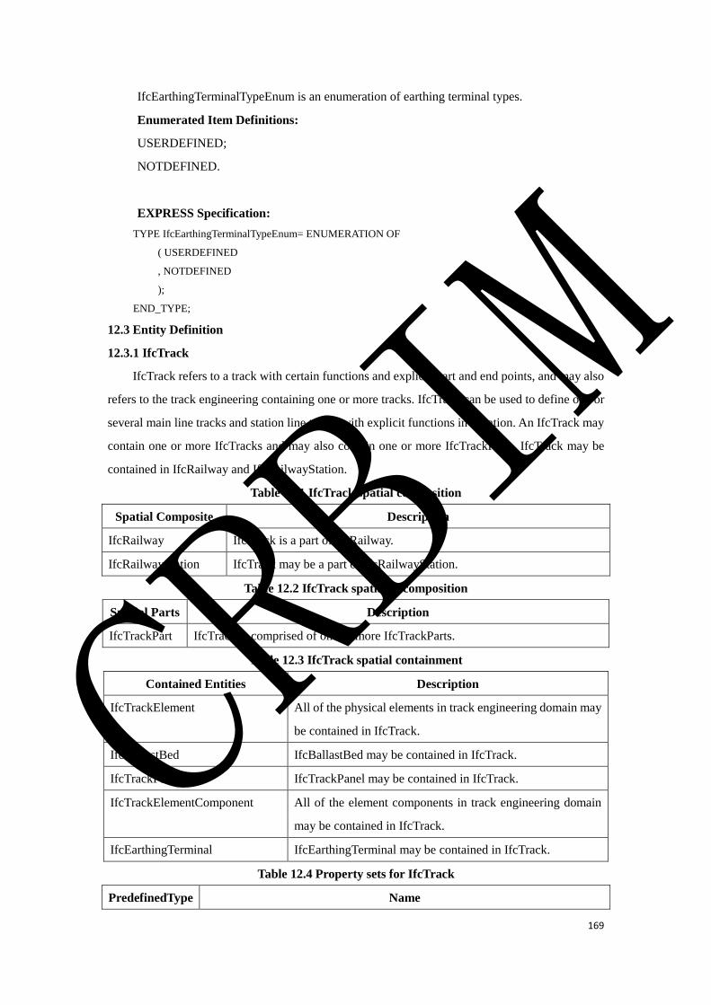
169
IfcEarthingTerminalTypeEnum is an enumeration of earthing terminal types.
Enumerated Item Definitions:
USERDEFINED;
NOTDEFINED.
EXPRESS Specification:
TYPE IfcEarthingTerminalTypeEnum= ENUMERATION OF
( USERDEFINED
, NOTDEFINED
);
END_TYPE;
12.3 Entity Definition
12.3.1 IfcTrack
IfcTrack refers to a track with certain functions and explicit start and end points, and may also
refers to the track engineering containing one or more tracks. IfcTrack can be used to define one or
several main line tracks and station line tracks with explicit functions in a station. An IfcTrack may
contain one or more IfcTracks and may also contain one or more IfcTrackParts. IfcTrack may be
contained in IfcRailway and IfcRailwayStation.
Table 12.1 IfcTrack spatial composition
Spatial Composite Description
IfcRailway IfcTrack is a part of IfcRailway.
IfcRailwayStation IfcTrack may be a part of IfcRailwayStation.
Table 12.2 IfcTrack spatial decomposition
Spatial Parts Description
IfcTrackPart IfcTrack is comprised of one or more IfcTrackParts.
Table 12.3 IfcTrack spatial containment
Contained Entities Description
IfcTrackElement All of the physical elements in track engineering domain may
be contained in IfcTrack.
IfcBallastBed IfcBallastBed may be contained in IfcTrack.
IfcTrackPanel IfcTrackPanel may be contained in IfcTrack.
IfcTrackElementComponent All of the element components in track engineering domain
may be contained in IfcTrack.
IfcEarthingTerminal IfcEarthingTerminal may be contained in IfcTrack.
Table 12.4 Property sets for IfcTrack
PredefinedType Name
CRBIM

170
Pset_TrackCommon
EXPRESS Specification:
ENTITY IfcTrack
SUBTYPE OF (IfcRailwayStructureElement);
PreDefinedType: IfcTrackTypeEnum;
RouteDirectionType: IfcTrackRouteDirectionTypeEnum;
RouteFunctionType: IfcTrackRouteFunctionTypeEnum;
END_ENTITY;
Attribute definitions:
PreDefinedType: It defines the functional types of a track, such as MAINTRACK,
CONNECTINGLINE, RUNNINGTRACKFORMULTIPLEUNIT, UNTWININGLINE,
RECEIVINGDEPATURETRACK, SWITCHINGLEAD, CATCHSIDING, FREIGHTTRACK,
CLASSIFICATIONTRACK, LOCOMOTIVERUNNINGTRACK, REFUGESIDING,
ROUNDABOUTLINE, ROLLINGFORBIDDENTRACK, ROLLINGTRACK,
LOCOMOTIVESERVICETRACK, LOCOMOTIVEHOLDTRACK, STORAGETRACK,
REPAIRSIDING, etc.
RouteDirectionType: It defines the permissible directions of a train on a track route, such as
UPDIRECTIONROUTE, DOWNDIRECTIONROUTE, and EITHERDIRECTIONALROUTE.
RouteFunctionType: It defines the permissible train types on a track route, such as
PASSENGERLINE, FREIGHTLINE, PASSENGERFREIGHTLINE,
ENTERDEPOTLINEFORLOCOMOTIVE, EXITDEPOTLINEFORLOCOMOTIVE, etc.
12.3.2 IfcTrackPart
IfcTrackPart refers to a segment of track engineering which is part of the IfcTrack and has a
unique structural type and functional type.
Table 12.5 IfcTrackPart spatial composition
Spatial Composite Description
IfcTrack IfcTrackPart is a part of IfcTrack.
Table 12.6 IfcTrackPart spatial containment
Contained Entities Description
IfcTrackElement All of the physical elements in track engineering domain may be
contained in IfcTrackPart.
IfcBallastBed IfcBallastBed may be contained in IfcTrackPart.
IfcTrackPanel IfcTrackPanel may be contained in IfcTrackPart.
IfcTrackElementComponent All of the element components in track engineering domain may
be contained in IfcTrackPart.
IfcEarthingTerminal IfcEarthingTerminal may be contained in IfcTrackPart.
CRBIM
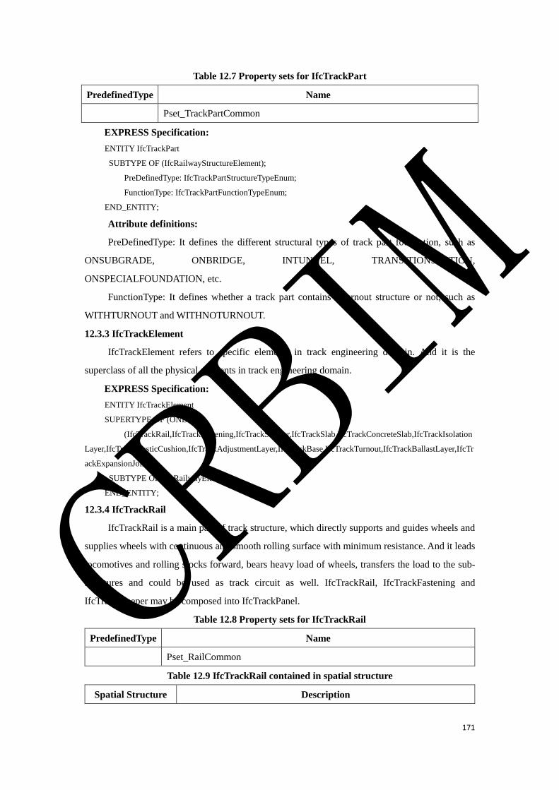
171
Table 12.7 Property sets for IfcTrackPart
PredefinedType Name
Pset_TrackPartCommon
EXPRESS Specification:
ENTITY IfcTrackPart
SUBTYPE OF (IfcRailwayStructureElement);
PreDefinedType: IfcTrackPartStructureTypeEnum;
FunctionType: IfcTrackPartFunctionTypeEnum;
END_ENTITY;
Attribute definitions:
PreDefinedType: It defines the different structural types of track part foundation, such as
ONSUBGRADE, ONBRIDGE, INTUNNEL, TRANSITIONSECTION,
ONSPECIALFOUNDATION, etc.
FunctionType: It defines whether a track part contains a turnout structure or not, such as
WITHTURNOUT and WITHNOTURNOUT.
12.3.3 IfcTrackElement
IfcTrackElement refers to specific elements in track engineering domain. And it is the
superclass of all the physical elements in track engineering domain.
EXPRESS Specification:
ENTITY IfcTrackElement
SUPERTYPE OF (ONEOF
(IfcTrackRail,IfcTrackFastening,IfcTrackSleeper,IfcTrackSlab,IfcTrackConcreteSlab,IfcTrackIsolation
Layer,IfcTrackElasticCushion,IfcTrackAdjustmentLayer,IfcTrackBase,IfcTrackTurnout,IfcTrackBallastLayer,IfcTr
ackExpansionJoint))
SUBTYPE OF (IfcRailwayElement);
END_ENTITY;
12.3.4 IfcTrackRail
IfcTrackRail is a main part of track structure, which directly supports and guides wheels and
supplies wheels with continuous and smooth rolling surface with minimum resistance. And it leads
locomotives and rolling stocks forward, bears heavy load of wheels, transfers the load to the sub-
structures and could be used as track circuit as well. IfcTrackRail, IfcTrackFastening and
IfcTrackSleeper may be composed into IfcTrackPanel.
Table 12.8 Property sets for IfcTrackRail
PredefinedType Name
Pset_RailCommon
Table 12.9 IfcTrackRail contained in spatial structure
Spatial Structure Description
CRBIM
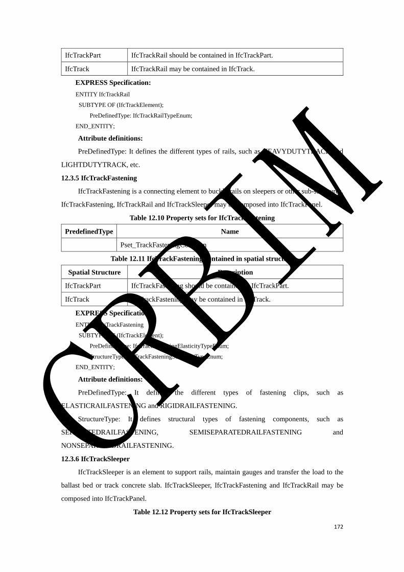
172
IfcTrackPart IfcTrackRail should be contained in IfcTrackPart.
IfcTrack IfcTrackRail may be contained in IfcTrack.
EXPRESS Specification:
ENTITY IfcTrackRail
SUBTYPE OF (IfcTrackElement);
PreDefinedType: IfcTrackRailTypeEnum;
END_ENTITY;
Attribute definitions:
PreDefinedType: It defines the different types of rails, such as HEAVYDUTYTRACK and
LIGHTDUTYTRACK, etc.
12.3.5 IfcTrackFastening
IfcTrackFastening is a connecting element to buckle rails on sleepers or other sub-structures.
IfcTrackFastening, IfcTrackRail and IfcTrackSleeper may be composed into IfcTrackPanel.
Table 12.10 Property sets for IfcTrackFastening
PredefinedType Name
Pset_TrackFasteningCommon
Table 12.11 IfcTrackFastening contained in spatial structure
Spatial Structure Description
IfcTrackPart IfcTrackFastening should be contained in IfcTrackPart.
IfcTrack IfcTrackFastening may be contained in IfcTrack.
EXPRESS Specification:
ENTITY IfcTrackFastening
SUBTYPE OF (IfcTrackElement);
PreDefinedType: IfcTrackFasteningElasticityTypeEnum;
StructureType: IfcTrackFasteningStructureTypeEnum;
END_ENTITY;
Attribute definitions:
PreDefinedType: It defines the different types of fastening clips, such as
ELASTICRAILFASTENING and RIGIDRAILFASTENING.
StructureType: It defines structural types of fastening components, such as
SEPARATEDRAILFASTENING, SEMISEPARATEDRAILFASTENING and
NONSEPARATEDRAILFASTENING.
12.3.6 IfcTrackSleeper
IfcTrackSleeper is an element to support rails, maintain gauges and transfer the load to the
ballast bed or track concrete slab. IfcTrackSleeper, IfcTrackFastening and IfcTrackRail may be
composed into IfcTrackPanel.
Table 12.12 Property sets for IfcTrackSleeper
CRBIM
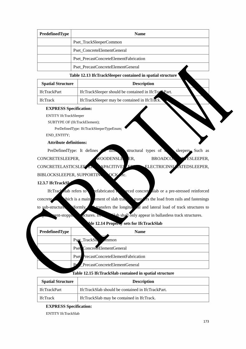
173
PredefinedType Name
Pset_TrackSleeperCommon
Pset_ConcreteElementGeneral
Pset_PrecastConcreteElementFabrication
Pset_PrecastConcreteElementGeneral
Table 12.13 IfcTrackSleeper contained in spatial structure
Spatial Structure Description
IfcTrackPart IfcTrackSleeper should be contained in IfcTrackPart.
IfcTrack IfcTrackSleeper may be contained in IfcTrack.
EXPRESS Specification:
ENTITY IfcTrackSleeper
SUBTYPE OF (IfcTrackElement);
PreDefinedType: IfcTrackSleeperTypeEnum;
END_ENTITY;
Attribute definitions:
PreDefinedType: It defines the different structural types of track sleepers. Such as
CONCRETESLEEPER, WOODENSLEEPER, BROADCONCRETESLEEPER,
CONCRETELASTICSLEEPER, CAPACITIVESLEEPER, ELECTRICINSULATEDSLEEPER,
BIBLOCKSLEEPER, SUPPORTINGBLOCK, etc.
12.3.7 IfcTrackSlab
IfcTrackSlab refers to a prefabricated reinforced concrete slab or a pre-stressed reinforced
concrete slab, which is a main element of slab track. It transfers the load from rails and fastenings
to sub-structures uniformly, and transfers the longitudinal and lateral load of track structures to
displacement-stopping structures. IfcTrackSlab shall only appear in ballastless track structures.
Table 12.14 Property sets for IfcTrackSlab
PredefinedType Name
Pset_TrackSlabCommon
Pset_ConcreteElementGeneral
Pset_PrecastConcreteElementFabrication
Pset_PrecastConcreteElementGeneral
Table 12.15 IfcTrackSlab contained in spatial structure
Spatial Structure Description
IfcTrackPart IfcTrackSlab should be contained in IfcTrackPart.
IfcTrack IfcTrackSlab may be contained in IfcTrack.
EXPRESS Specification:
ENTITY IfcTrackSlab
CRBIM
174
SUBTYPE OF (IfcTrackElement);
PreDefinedType: IfcTrackSlabTypeEnum;
END_ENTITY;
Attribute definitions:
PreDefinedType: It defines whether the track slab is pre-stressed or not and the different pre-
stressed types of track slab. Such as NONPRESTRESSEDTRACKSLAB,
UNIDIRECTIONALPRESTRESSEDTRACKSLAB and
BIDIRECTIONALPRESTRESSEDTRACKSLAB.
12.3.8 IfcTrackConcreteSlab
IfcTrackConcreteSlab refers to an integral reinforced concrete layer cast in-situ, in which bi-
block sleepers, concrete turnout sleepers or other sleepers are embedded. IfcTrackConcreteSlab
shall only appear in ballastless track structures.
Table 12.16 Property sets for IfcTrackConcreteSlab
PredefinedType Name
Pset_ConcreteElementGeneral
Table 12.17 IfcTrackConcreteSlab contained in spatial structure
Spatial Structure Description
IfcTrackPart IfcTrackConcreteSlab should be contained in IfcTrackPart.
IfcTrack IfcTrackConcreteSlab may be contained in IfcTrack.
EXPRESS Specification:
ENTITY IfcTrackConcreteSlab
SUBTYPE OF (IfcTrackElement);
PreDefinedType: IfcTrackConcreteSlabTypeEnum;
END_ENTITY;
Attribute definitions:
PreDefinedType.
12.3.9 IfcTrackIsolationLayer
IfcTrackIsolationLayer is a structure layer placed on the top surface of track bases. It may
implement the damage repair of track superstructure under special circumstances and coordinate
temperature deformation. IfcTrackIsolationLayer shall only appear in ballastless track structures.
Table 12.18 Property sets for IfcTrackIsolationLayer
PredefinedType Name
Pset_TrackIsolationLayerCommon
Table 12.19 IfcTrackIsolationLayer contained in spatial structure
Spatial Structure Description
IfcTrackPart IfcTrackIsolationLayer should be contained in IfcTrackPart.
CRBIM
175
IfcTrack IfcTrackIsolationLayer may be contained in IfcTrack.
EXPRESS Specification:
ENTITY IfcTrackIsolationLayer
SUBTYPE OF (IfcTrackElement);
PreDefinedType: IfcTrackIsolationLayerTypeEnum;
END_ENTITY;
Attribute definitions:
PreDefinedType.
12.3.10 IfcTrackElasticCushion
IfcTrackElasticCushion is a kind of layer set on trough sides of a concrete base, which is used
for mitigating the impact of longitudinal and lateral load on track structures. IfcTrackElasticCushion
shall only appear in ballastless track structures.
Table 12.20 Property sets for IfcTrackElasticCushion
PredefinedType Name
Pset_TrackElasticCushionCommon
Table 12.21 IfcTrackElasticCushion contained in spatial structure
Spatial Structure Description
IfcTrackPart IfcTrackElasticCushion should be contained in IfcTrackPart.
IfcTrack IfcTrackElasticCushion may be contained in IfcTrack.
EXPRESS Specification:
ENTITY IfcTrackElasticCushion
SUBTYPE OF (IfcTrackElement);
PreDefinedType: IfcTrackElasticCushionTypeEnum;
END_ENTITY;
Attribute definitions:
PreDefinedType.
12.3.11 IfcTrackAdjustmentLayer
IfcTrackAdjustmentLayer is a concrete layer or a mortar layer cast or paved in-situ to support
track slabs or track concrete slabs. IfcTrackAdjustmentLayer shall only appear in ballastless track
structures.
Table 12.22 Property sets for IfcTrackAdjustmentLayer
PredefinedType Name
Pset_TrackAdjustmentlayerCommon
Table 12.23 IfcTrackAdjustmentLayer contained in spatial structure
Spatial Structure Description
IfcTrackPart IfcTrackAdjustmentLayer should be contained in IfcTrackPart.
CRBIM
176
IfcTrack IfcTrackAdjustmentLayer may be contained in IfcTrack.
EXPRESS Specification:
ENTITY IfcTrackAdjustmentLayer
SUBTYPE OF (IfcTrackElement);
PreDefinedType: IfcTrackAdjustmentlayerTypeEnum;
END_ENTITY;
Attribute definitions:
PreDefinedType.
12.3.12 IfcTrackBase
IfcTrackBase is a kind of reinforced foundation cast in-situ to support track slabs or track
concrete slabs. IfcTrackBase shall only appear in ballastless track structures.
Table 12.24 Property sets for IfcTrackBase
PredefinedType Name
Pset_TrackBaseCommon
Pset_ConcreteElementGeneral
Table 12.25 IfcTrackBase contained in spatial structure
Spatial Structure Description
IfcTrackPart IfcTrackBase should be contained in IfcTrackPart.
IfcTrack IfcTrackBase may be contained in IfcTrack.
EXPRESS Specification:
ENTITY IfcTrackBase
SUBTYPE OF (IfcTrackElement);
PreDefinedType: IfcTrackBaseTypeEnum;
END_ENTITY;
Attribute definitions:
PreDefinedType.
12.3.13 IfcTrackTurnout
IfcTrackTurnout is a facility which transforms one track into two or more tracks.
Table 12.26 Property sets for IfcTrackTurnout
PredefinedType Name
Pset_TurnoutCommon
Table 12.27 IfcTrackTurnout contained in spatial structure
Spatial Structure Description
IfcTrackPart IfcTrackTurnout should be contained in all the types of IfcTrackPart
except the type of WITHNOTURNOUT.
IfcTrack IfcTrackTurnout may be contained in IfcTrack.
EXPRESS Specification:
CRBIM

177
ENTITY IfcTrackTurnout
SUBTYPE OF (IfcTrackElement);
PreDefinedType: IfcTrackTurnoutTypeEnum;
END_ENTITY;
Attribute definitions:
PreDefinedType: It defines the different structural types of track turnouts. Such as
LEFTHANDTURNOUT, RIGHTHANDTURNOUT, SYMMETRICALTURNOUT,
SLIPTOURNOUT, SCISSORSCROSSING and
COMBINATIONOFSLIPTURNOUTANDSCISSORSCROSSING, etc.
12.3.14 IfcTrackBallastLayer
IfcTrackBallastLayer is a structure layer which comprises different kinds of granular materials
with different particle size grading, such as crushed stones, pebbles, sands, slags and so on. It can
directly support or fix sleepers, transfer loads and play a role in drainage system, etc. One or more
IfcTrackBallastLayer may be composed into an IfcBallastBed. IfcTrackBallastLayer shall only
appear in ballasted track structures.
Table 12.28 Property sets for IfcTrackBallastLayer
PredefinedType Name
Pset_TrackBallastLayerCommon
Table 12.29 IfcTrackBallastLayer contained in spatial structure
Spatial Structure Description
IfcTrackPart IfcTrackBallastLayer should be contained in IfcTrackPart.
IfcTrack IfcTrackBallastLayer may be contained in IfcTrack.
EXPRESS Specification:
ENTITY IfcTrackBallastLayer
SUBTYPE OF (IfcTrackElement);
PreDefinedType: IfcTrackBallastLayerTypeEnum;
END_ENTITY;
Attribute definitions:
PreDefinedType: It defines the different functional types of ballast layers. Such as
TOPBALLAST, SUBBALLAST, SPACEFILLEDBALLAST, etc.
12.3.15 IfcTrackExpansionJoint
IfcTrackExpansionJoint is a facility to adjust the expansion of rails.
Table 12.30 Property sets for IfcTrackExpansionJoint
PredefinedType Name
Pset_TrackExpansionJointCommon
Table 12.31 IfcTrackExpansionJoint contained in spatial structure
Spatial Structure Description
CRBIM
178
IfcTrackPart IfcTrackExpansionJoint should be contained in IfcTrackPart.
IfcTrack IfcTrackExpansionJoint may be contained in IfcTrack.
EXPRESS Specification:
ENTITY IfcTrackExpansionJoint
SUBTYPE OF (IfcTrackElement);
PreDefinedType: IfcTrackExpansionJointTypeEnum;
END_ENTITY;
Attribute definitions:
PreDefinedType: It defines the different structural types of expansion joints. Such as
SINGLEDIRECTION and BIDIRECTION.
12.3.16 IfcRailwayAssembly
IfcRailwayAssembly refers to specific element assemblies in track engineering domain. And
it is the superclass of all the element assemblies in track engineering domain.
EXPRESS Specification:
ENTITY IfcRailwayAssembly
SUPERTYPE OF (ONEOF
(IfcBallastBed, IfcTrackPanel))
SUBTYPE OF (IfcCivilElementAssembly);
END_ENTITY;
12.3.17 IfcBallastBed
IfcBallastBed is a part of track structure to support and fix sleepers, which transfers and
distributes its load to the top surface of sub-structures. IfcBallastBed shall only appear in ballasted
track structures. One IfcBallastBed may contain one or more IfcTrackBallastLayer.
Table 12.32 IfcBallastBed contained in spatial structure
Spatial Structure Description
IfcTrackPart IfcBallastBed should be contained in IfcTrackPart.
IfcTrack IfcBallastBed may be contained in IfcTrack.
Table 12.33 IfcBallastBed entity composition
PredefinedType Contained Entities Description
IfcTrackBallastLayer IfcBallastBed may contain IfcTrackBallastLayer.
EXPRESS Specification:
ENTITY IfcBallastBed
SUBTYPE OF (IfcRailwayAssembly);
PreDefinedType: IfcBallastBedTypeEnum;
END_ENTITY;
Attribute definitions:
PreDefinedType.
12.3.18 IfcTrackPanel
CRBIM
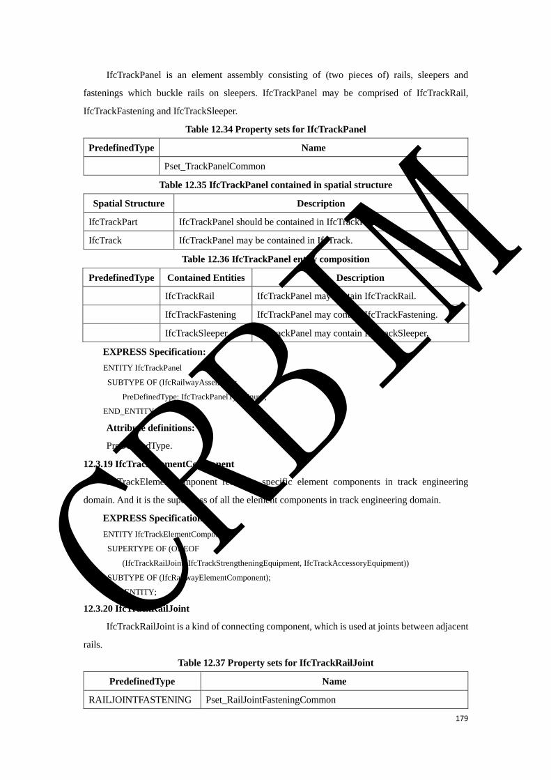
179
IfcTrackPanel is an element assembly consisting of (two pieces of) rails, sleepers and
fastenings which buckle rails on sleepers. IfcTrackPanel may be comprised of IfcTrackRail,
IfcTrackFastening and IfcTrackSleeper.
Table 12.34 Property sets for IfcTrackPanel
PredefinedType Name
Pset_TrackPanelCommon
Table 12.35 IfcTrackPanel contained in spatial structure
Spatial Structure Description
IfcTrackPart IfcTrackPanel should be contained in IfcTrackPart.
IfcTrack IfcTrackPanel may be contained in IfcTrack.
Table 12.36 IfcTrackPanel entity composition
PredefinedType Contained Entities Description
IfcTrackRail IfcTrackPanel may contain IfcTrackRail.
IfcTrackFastening IfcTrackPanel may contain IfcTrackFastening.
IfcTrackSleeper IfcTrackPanel may contain IfcTrackSleeper.
EXPRESS Specification:
ENTITY IfcTrackPanel
SUBTYPE OF (IfcRailwayAssembly);
PreDefinedType: IfcTrackPanelTypeEnum;
END_ENTITY;
Attribute definitions:
PreDefinedType.
12.3.19 IfcTrackElementComponent
IfcTrackElementComponent refers to specific element components in track engineering
domain. And it is the superclass of all the element components in track engineering domain.
EXPRESS Specification:
ENTITY IfcTrackElementComponent
SUPERTYPE OF (ONEOF
(IfcTrackRailJoint, IfcTrackStrengtheningEquipment, IfcTrackAccessoryEquipment))
SUBTYPE OF (IfcRailwayElementComponent);
END_ENTITY;
12.3.20 IfcTrackRailJoint
IfcTrackRailJoint is a kind of connecting component, which is used at joints between adjacent
rails.
Table 12.37 Property sets for IfcTrackRailJoint
PredefinedType Name
RAILJOINTFASTENING Pset_RailJointFasteningCommon
CRBIM
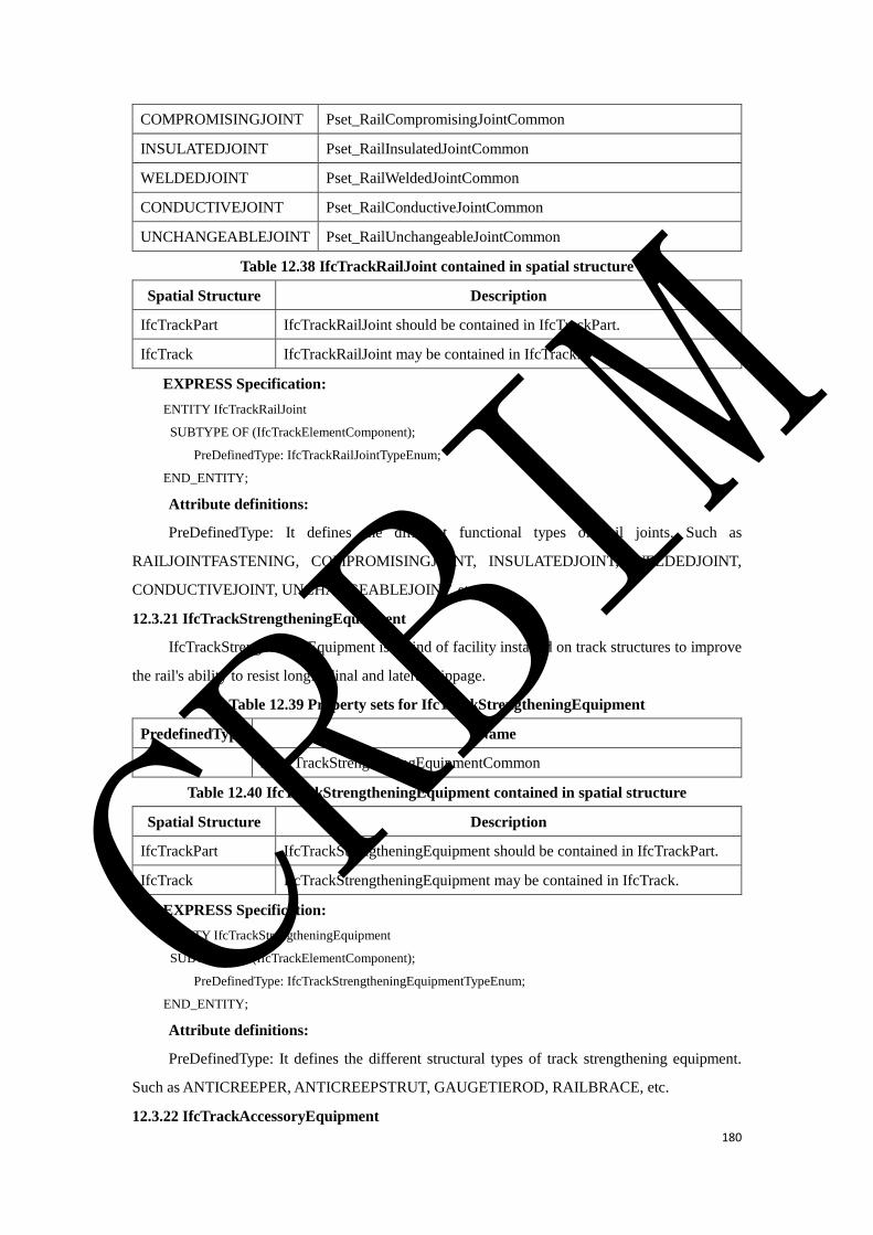
180
COMPROMISINGJOINT Pset_RailCompromisingJointCommon
INSULATEDJOINT Pset_RailInsulatedJointCommon
WELDEDJOINT Pset_RailWeldedJointCommon
CONDUCTIVEJOINT Pset_RailConductiveJointCommon
UNCHANGEABLEJOINT Pset_RailUnchangeableJointCommon
Table 12.38 IfcTrackRailJoint contained in spatial structure
Spatial Structure Description
IfcTrackPart IfcTrackRailJoint should be contained in IfcTrackPart.
IfcTrack IfcTrackRailJoint may be contained in IfcTrack.
EXPRESS Specification:
ENTITY IfcTrackRailJoint
SUBTYPE OF (IfcTrackElementComponent);
PreDefinedType: IfcTrackRailJointTypeEnum;
END_ENTITY;
Attribute definitions:
PreDefinedType: It defines the different functional types of rail joints. Such as
RAILJOINTFASTENING, COMPROMISINGJOINT, INSULATEDJOINT, WELDEDJOINT,
CONDUCTIVEJOINT, UNCHANGEABLEJOINT, etc.
12.3.21 IfcTrackStrengtheningEquipment
IfcTrackStrengtheningEquipment is a kind of facility installed on track structures to improve
the rail's ability to resist longitudinal and lateral slippage.
Table 12.39 Property sets for IfcTrackStrengtheningEquipment
PredefinedType Name
Pset_TrackStrengtheningEquipmentCommon
Table 12.40 IfcTrackStrengtheningEquipment contained in spatial structure
Spatial Structure Description
IfcTrackPart IfcTrackStrengtheningEquipment should be contained in IfcTrackPart.
IfcTrack IfcTrackStrengtheningEquipment may be contained in IfcTrack.
EXPRESS Specification:
ENTITY IfcTrackStrengtheningEquipment
SUBTYPE OF (IfcTrackElementComponent);
PreDefinedType: IfcTrackStrengtheningEquipmentTypeEnum;
END_ENTITY;
Attribute definitions:
PreDefinedType: It defines the different structural types of track strengthening equipment.
Such as ANTICREEPER, ANTICREEPSTRUT, GAUGETIEROD, RAILBRACE, etc.
12.3.22 IfcTrackAccessoryEquipment
CRBIM
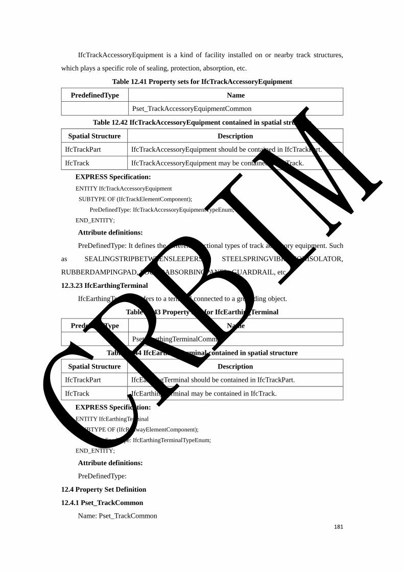
181
IfcTrackAccessoryEquipment is a kind of facility installed on or nearby track structures,
which plays a specific role of sealing, protection, absorption, etc.
Table 12.41 Property sets for IfcTrackAccessoryEquipment
PredefinedType Name
Pset_TrackAccessoryEquipmentCommon
Table 12.42 IfcTrackAccessoryEquipment contained in spatial structure
Spatial Structure Description
IfcTrackPart IfcTrackAccessoryEquipment should be contained in IfcTrackPart.
IfcTrack IfcTrackAccessoryEquipment may be contained in IfcTrack.
EXPRESS Specification:
ENTITY IfcTrackAccessoryEquipment
SUBTYPE OF (IfcTrackElementComponent);
PreDefinedType: IfcTrackAccessoryEquipmentTypeEnum;
END_ENTITY;
Attribute definitions:
PreDefinedType: It defines the different functional types of track accessory equipment. Such
as SEALINGSTRIPBETWEENSLEEPERS, STEELSPRINGVIBRATIONISOLATOR,
RUBBERDAMPINGPAD, SOUNDABSORBINGPANEL, GUARDRAIL, etc.
12.3.23 IfcEarthingTerminal
IfcEarthingTerminal refers to a terminal connected to a grounding object.
Table 12.43 Property sets for IfcEarthingTerminal
PredefinedType Name
Pset_EarthingTerminalCommon
Table 12.44 IfcEarthingTerminal contained in spatial structure
Spatial Structure Description
IfcTrackPart IfcEarthingTerminal should be contained in IfcTrackPart.
IfcTrack IfcEarthingTerminal may be contained in IfcTrack.
EXPRESS Specification:
ENTITY IfcEarthingTerminal
SUBTYPE OF (IfcRailwayElementComponent);
PreDefinedType: IfcEarthingTerminalTypeEnum;
END_ENTITY;
Attribute definitions:
PreDefinedType:
12.4 Property Set Definition
12.4.1 Pset_TrackCommon
Name: Pset_TrackCommon
CRBIM
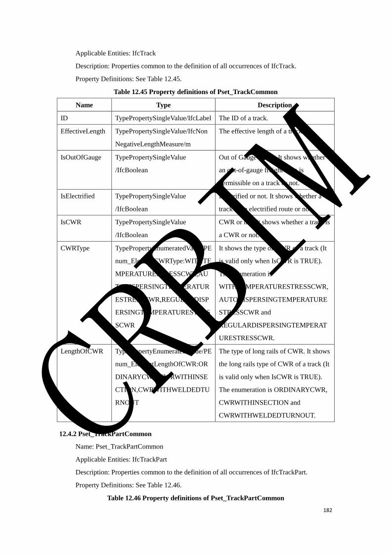
182
Applicable Entities: IfcTrack
Description: Properties common to the definition of all occurrences of IfcTrack.
Property Definitions: See Table 12.45.
Table 12.45 Property definitions of Pset_TrackCommon
Name Type Description
ID TypePropertySingleValue/IfcLabel The ID of a track.
EffectiveLength TypePropertySingleValue/IfcNon
NegativeLengthMeasure/m
The effective length of a track.
IsOutOfGauge TypePropertySingleValue
/IfcBoolean
Out of Gauge or not. It shows whether
an out-of-gauge freight train is
permissible on a track or not.
IsElectrified TypePropertySingleValue
/IfcBoolean
Electrified or not. It shows whether a
track is an electrified route or not.
IsCWR TypePropertySingleValue
/IfcBoolean
CWR or not. It shows whether a track is
a CWR or not.
CWRType TypePropertyEnumeratedValue/PE
num_ElementCWRType:WITHTE
MPERATURESTRESSCWR,AU
TODISPERSINGTEMPERATUR
ESTRESSCWR,REGULARDISP
ERSINGTEMPERATURESTRES
SCWR
It shows the type of CWR of a track (It
is valid only when IsCWR is TRUE).
The enumeration is
WITHTEMPERATURESTRESSCWR,
AUTODISPERSINGTEMPERATURE
STRESSCWR and
REGULARDISPERSINGTEMPERAT
URESTRESSCWR.
LengthOfCWR TypePropertyEnumeratedValue/PE
num_ElementLengthOfCWR:OR
DINARYCWR,CWRWITHINSE
CTION,CWRWITHWELDEDTU
RNOUT
The type of long rails of CWR. It shows
the long rails type of CWR of a track (It
is valid only when IsCWR is TRUE).
The enumeration is ORDINARYCWR,
CWRWITHINSECTION and
CWRWITHWELDEDTURNOUT.
12.4.2 Pset_TrackPartCommon
Name: Pset_TrackPartCommon
Applicable Entities: IfcTrackPart
Description: Properties common to the definition of all occurrences of IfcTrackPart.
Property Definitions: See Table 12.46.
Table 12.46 Property definitions of Pset_TrackPartCommon
CRBIM
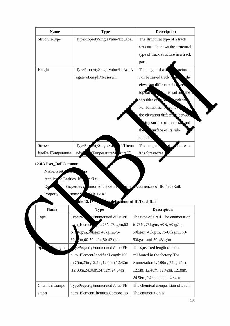
183
Name Type Description
StructureType TypePropertySingleValue/IfcLabel The structural type of a track
structure. It shows the structural
type of track structure in a track
part.
Height TypePropertySingleValue/IfcNonN
egativeLengthMeasure/m
The height of a track structure.
For ballasted track, it shows the
elevation difference between the
top surface of inner rail and the
shoulder of its sub-foundations.
For ballastless track, it shows
the elevation difference between
the top surface of inner rail and
the top surface of its sub-
foundations.
Stress-
freeRailTemperature
TypePropertySingleValue/IfcTherm
odynamicTemperatureMeasure/℃
The temperature of the rail when
it is Stress-free.
12.4.3 Pset_RailCommon
Name: Pset_RailCommon
Applicable Entities: IfcTrackRail
Description: Properties common to the definition of all occurrences of IfcTrackRail.
Property Definitions: See Table 12.47.
Table 12.47 Property definitions of IfcTrackRail
Name Type Description
Type TypePropertyEnumeratedValue/PE
num_ElementType:75N,75kg/m,60
N,60kg/m,50kg/m,43kg/m,75-
60kg/m,60-50kg/m,50-43kg/m
The type of a rail. The enumeration
is 75N, 75kg/m, 60N, 60kg/m,
50kg/m, 43kg/m, 75-60kg/m, 60-
50kg/m and 50-43kg/m.
SpecifiedLength TypePropertyEnumeratedValue/PE
num_ElementSpecifiedLength:100
m,75m,25m,12.5m,12.46m,12.42m
,12.38m,24.96m,24.92m,24.84m
The specified length of a rail
calibrated in the factory. The
enumeration is 100m, 75m, 25m,
12.5m, 12.46m, 12.42m, 12.38m,
24.96m, 24.92m and 24.84m.
ChemicalCompo
sition
TypePropertyEnumeratedValue/PE
num_ElementChemicalCompositio
The chemical composition of a rail.
The enumeration is
CRBIM
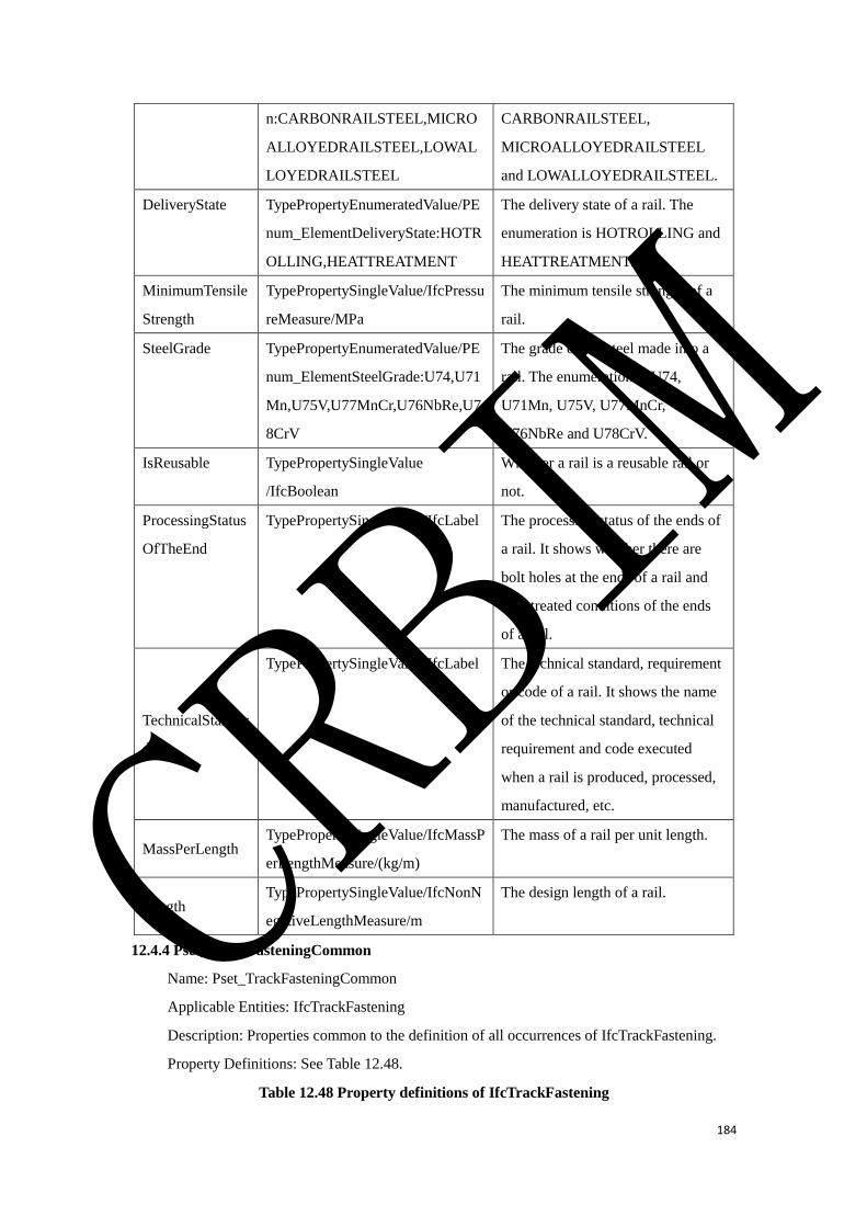
184
n:CARBONRAILSTEEL,MICRO
ALLOYEDRAILSTEEL,LOWAL
LOYEDRAILSTEEL
CARBONRAILSTEEL,
MICROALLOYEDRAILSTEEL
and LOWALLOYEDRAILSTEEL.
DeliveryState TypePropertyEnumeratedValue/PE
num_ElementDeliveryState:HOTR
OLLING,HEATTREATMENT
The delivery state of a rail. The
enumeration is HOTROLLING and
HEATTREATMENT.
MinimumTensile
Strength
TypePropertySingleValue/IfcPressu
reMeasure/MPa
The minimum tensile strength of a
rail.
SteelGrade TypePropertyEnumeratedValue/PE
num_ElementSteelGrade:U74,U71
Mn,U75V,U77MnCr,U76NbRe,U7
8CrV
The grade of the steel made into a
rail. The enumeration is U74,
U71Mn, U75V, U77MnCr,
U76NbRe and U78CrV.
IsReusable TypePropertySingleValue
/IfcBoolean
Whether a rail is a reusable rail or
not.
ProcessingStatus
OfTheEnd
TypePropertySingleValue/IfcLabel The processing status of the ends of
a rail. It shows whether there are
bolt holes at the ends of a rail and
heat treated conditions of the ends
of a rail.
TechnicalStandar
d
TypePropertySingleValue/IfcLabel The technical standard, requirement
or code of a rail. It shows the name
of the technical standard, technical
requirement and code executed
when a rail is produced, processed,
manufactured, etc.
MassPerLength TypePropertySingleValue/IfcMassP
erLengthMeasure/(kg/m)
The mass of a rail per unit length.
Length TypePropertySingleValue/IfcNonN
egativeLengthMeasure/m
The design length of a rail.
12.4.4 Pset_TrackFasteningCommon
Name: Pset_TrackFasteningCommon
Applicable Entities: IfcTrackFastening
Description: Properties common to the definition of all occurrences of IfcTrackFastening.
Property Definitions: See Table 12.48.
Table 12.48 Property definitions of IfcTrackFastening
CRBIM
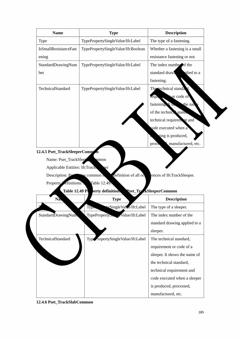
185
Name Type Description
Type TypePropertySingleValue/IfcLabel The type of a fastening.
IsSmallResistanceFast
ening
TypePropertySingleValue/IfcBoolean Whether a fastening is a small
resistance fastening or not.
StandardDrawingNum
ber
TypePropertySingleValue/IfcLabel The index number of the
standard drawing applied to a
fastening.
TechnicalStandard TypePropertySingleValue/IfcLabel The technical standard,
requirement or code of a
fastening. It shows the name
of the technical standard,
technical requirement and
code executed when a
fastening is produced,
processed, manufactured, etc.
12.4.5 Pset_TrackSleeperCommon
Name: Pset_TrackSleeperCommon
Applicable Entities: IfcTrackSleeper
Description: Properties common to the definition of all occurrences of IfcTrackSleeper.
Property Definitions: See Table 12.49.
Table 12.49 Property definitions of Pset_TrackSleeperCommon
Name Type Description
Type TypePropertySingleValue/IfcLabel The type of a sleeper.
StandardDrawingNumber TypePropertySingleValue/IfcLabel The index number of the
standard drawing applied to a
sleeper.
TechnicalStandard TypePropertySingleValue/IfcLabel The technical standard,
requirement or code of a
sleeper. It shows the name of
the technical standard,
technical requirement and
code executed when a sleeper
is produced, processed,
manufactured, etc.
12.4.6 Pset_TrackSlabCommon
CRBIM
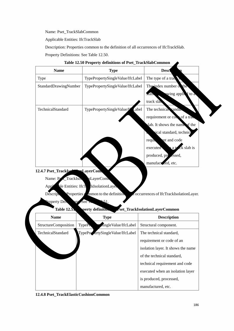
186
Name: Pset_TrackSlabCommon
Applicable Entities: IfcTrackSlab
Description: Properties common to the definition of all occurrences of IfcTrackSlab.
Property Definitions: See Table 12.50.
Table 12.50 Property definitions of Pset_TrackSlabCommon
Name Type Description
Type TypePropertySingleValue/IfcLabel The type of a track slab.
StandardDrawingNumber TypePropertySingleValue/IfcLabel The index number of the
standard drawing applied to a
track slab.
TechnicalStandard TypePropertySingleValue/IfcLabel The technical standard,
requirement or code of a track
slab. It shows the name of the
technical standard, technical
requirement and code
executed when a track slab is
produced, processed,
manufactured, etc.
12.4.7 Pset_TrackIsolationLayerCommon
Name: Pset_TrackIsolationLayerCommon
Applicable Entities: IfcTrackIsolationLayer
Description: Properties common to the definition of all occurrences of IfcTrackIsolationLayer.
Property Definitions: See Table 12.51.
Table 12.51 Property definitions of Pset_TrackIsolationLayerCommon
Name Type Description
StructureComposition TypePropertySingleValue/IfcLabel Structural component.
TechnicalStandard TypePropertySingleValue/IfcLabel The technical standard,
requirement or code of an
isolation layer. It shows the name
of the technical standard,
technical requirement and code
executed when an isolation layer
is produced, processed,
manufactured, etc.
12.4.8 Pset_TrackElasticCushionCommon
CRBIM
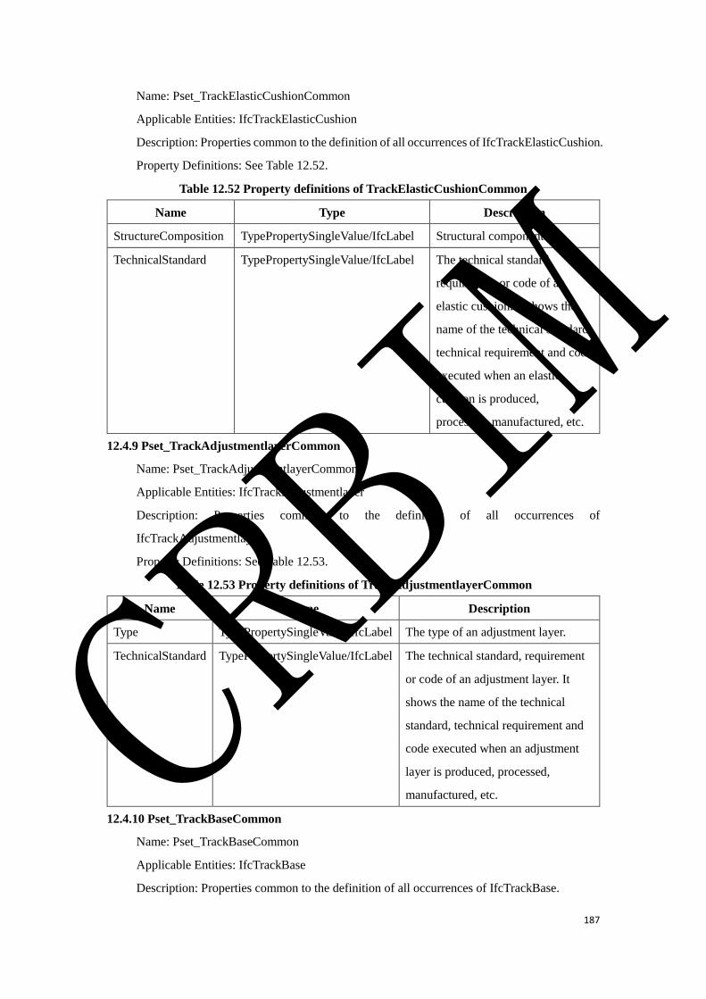
187
Name: Pset_TrackElasticCushionCommon
Applicable Entities: IfcTrackElasticCushion
Description: Properties common to the definition of all occurrences of IfcTrackElasticCushion.
Property Definitions: See Table 12.52.
Table 12.52 Property definitions of TrackElasticCushionCommon
Name Type Description
StructureComposition TypePropertySingleValue/IfcLabel Structural component.
TechnicalStandard TypePropertySingleValue/IfcLabel The technical standard,
requirement or code of an
elastic cushion. It shows the
name of the technical standard,
technical requirement and code
executed when an elastic
cushion is produced,
processed, manufactured, etc.
12.4.9 Pset_TrackAdjustmentlayerCommon
Name: Pset_TrackAdjustmentlayerCommon
Applicable Entities: IfcTrackAdjustmentlayer
Description: Properties common to the definition of all occurrences of
IfcTrackAdjustmentlayer.
Property Definitions: See Table 12.53.
Table 12.53 Property definitions of TrackAdjustmentlayerCommon
Name Type Description
Type TypePropertySingleValue/IfcLabel The type of an adjustment layer.
TechnicalStandard TypePropertySingleValue/IfcLabel The technical standard, requirement
or code of an adjustment layer. It
shows the name of the technical
standard, technical requirement and
code executed when an adjustment
layer is produced, processed,
manufactured, etc.
12.4.10 Pset_TrackBaseCommon
Name: Pset_TrackBaseCommon
Applicable Entities: IfcTrackBase
Description: Properties common to the definition of all occurrences of IfcTrackBase.
CRBIM
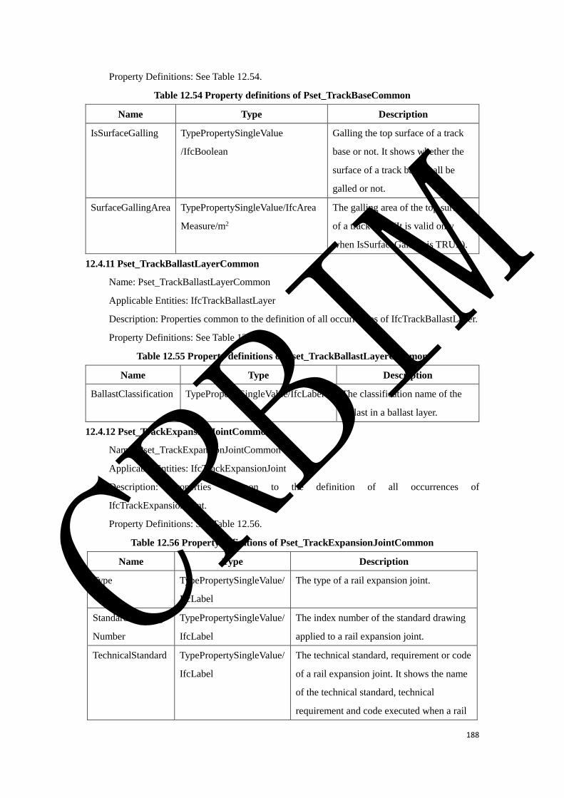
188
Property Definitions: See Table 12.54.
Table 12.54 Property definitions of Pset_TrackBaseCommon
Name Type Description
IsSurfaceGalling TypePropertySingleValue
/IfcBoolean
Galling the top surface of a track
base or not. It shows whether the
surface of a track base shall be
galled or not.
SurfaceGallingArea TypePropertySingleValue/IfcArea
Measure/m2
The galling area of the top surface
of a track base (It is valid only
when IsSurfaceGalling is TRUE).
12.4.11 Pset_TrackBallastLayerCommon
Name: Pset_TrackBallastLayerCommon
Applicable Entities: IfcTrackBallastLayer
Description: Properties common to the definition of all occurrences of IfcTrackBallastLayer.
Property Definitions: See Table 12.55.
Table 12.55 Property definitions of Pset_TrackBallastLayerCommon
Name Type Description
BallastClassification TypePropertySingleValue/IfcLabel The classification name of the
ballast in a ballast layer.
12.4.12 Pset_TrackExpansionJointCommon
Name: Pset_TrackExpansionJointCommon
Applicable Entities: IfcTrackExpansionJoint
Description: Properties common to the definition of all occurrences of
IfcTrackExpansionJoint.
Property Definitions: See Table 12.56.
Table 12.56 Property definitions of Pset_TrackExpansionJointCommon
Name Type Description
Type TypePropertySingleValue/
IfcLabel
The type of a rail expansion joint.
StandardDrawing
Number
TypePropertySingleValue/
IfcLabel
The index number of the standard drawing
applied to a rail expansion joint.
TechnicalStandard TypePropertySingleValue/
IfcLabel
The technical standard, requirement or code
of a rail expansion joint. It shows the name
of the technical standard, technical
requirement and code executed when a rail
CRBIM
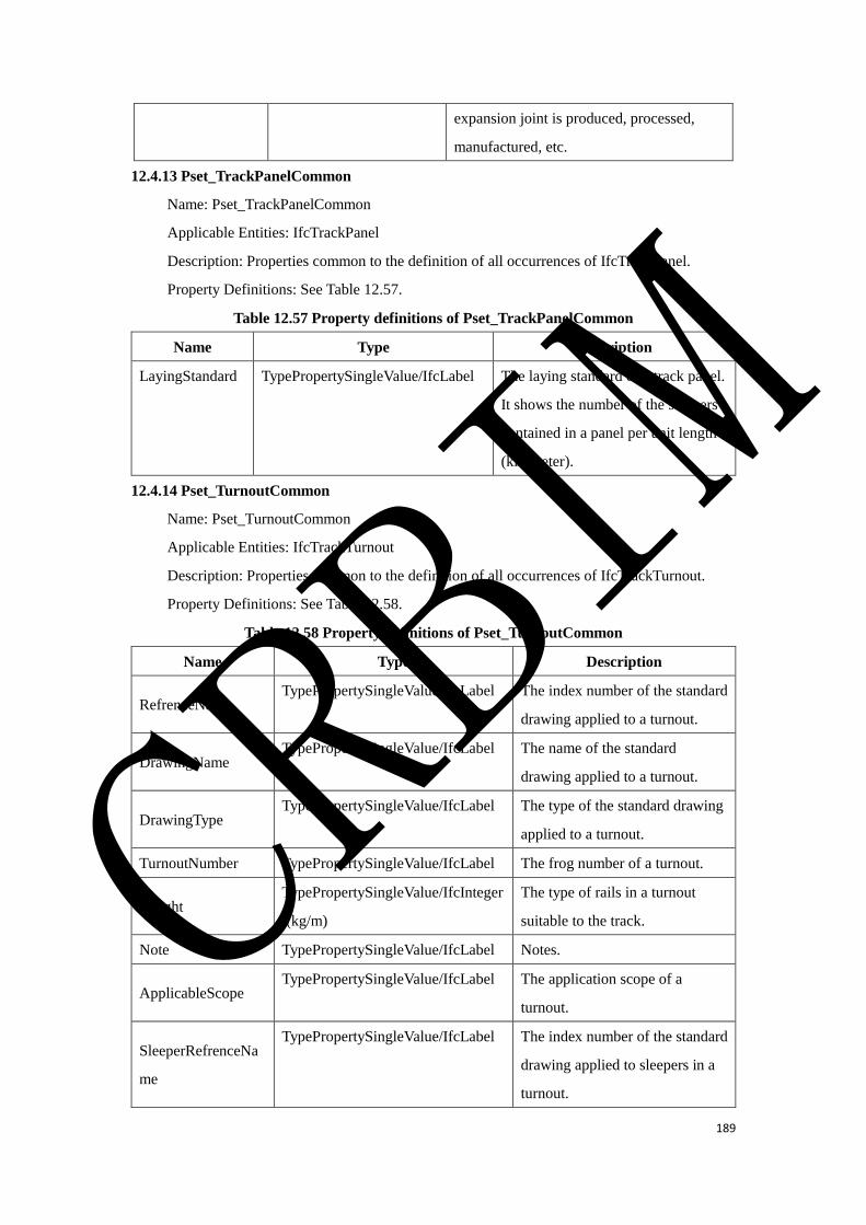
189
expansion joint is produced, processed,
manufactured, etc.
12.4.13 Pset_TrackPanelCommon
Name: Pset_TrackPanelCommon
Applicable Entities: IfcTrackPanel
Description: Properties common to the definition of all occurrences of IfcTrackPanel.
Property Definitions: See Table 12.57.
Table 12.57 Property definitions of Pset_TrackPanelCommon
Name Type Description
LayingStandard TypePropertySingleValue/IfcLabel The laying standard of a track panel.
It shows the number of the sleepers
contained in a panel per unit length
(kilometer).
12.4.14 Pset_TurnoutCommon
Name: Pset_TurnoutCommon
Applicable Entities: IfcTrackTurnout
Description: Properties common to the definition of all occurrences of IfcTrackTurnout.
Property Definitions: See Table 12.58.
Table 12.58 Property definitions of Pset_TurnoutCommon
Name Type Description
RefrenceName TypePropertySingleValue/IfcLabel The index number of the standard
drawing applied to a turnout.
DrawingName TypePropertySingleValue/IfcLabel The name of the standard
drawing applied to a turnout.
DrawingType TypePropertySingleValue/IfcLabel The type of the standard drawing
applied to a turnout.
TurnoutNumber TypePropertySingleValue/IfcLabel The frog number of a turnout.
Weight TypePropertySingleValue/IfcInteger
/(kg/m)
The type of rails in a turnout
suitable to the track.
Note TypePropertySingleValue/IfcLabel Notes.
ApplicableScope TypePropertySingleValue/IfcLabel The application scope of a
turnout.
SleeperRefrenceNa
me
TypePropertySingleValue/IfcLabel The index number of the standard
drawing applied to sleepers in a
turnout.
CRBIM
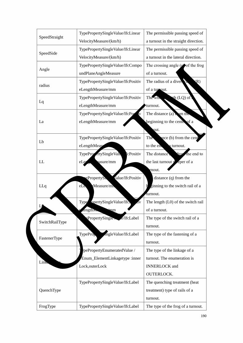
190
SpeedStraight TypePropertySingleValue/IfcLinear
VelocityMeasure/(km/h)
The permissible passing speed of
a turnout in the straight direction.
SpeedSide TypePropertySingleValue/IfcLinear
VelocityMeasure/(km/h)
The permissible passing speed of
a turnout in the lateral direction.
Angle TypePropertySingleValue/IfcCompo
undPlaneAngleMeasure
The crossing angle (α) of the frog
of a turnout.
radius TypePropertySingleValue/IfcPositiv
eLengthMeasure/mm
The radius of a divert curve (R)
of a turnout.
Lq TypePropertySingleValue/IfcPositiv
eLengthMeasure/mm
The whole length (LQ) of a
turnout.
La
TypePropertySingleValue/IfcPositiv
eLengthMeasure/mm
The distance (a) from the
beginning to the center of a
turnout.
Lb TypePropertySingleValue/IfcPositiv
eLengthMeasure/mm
The distance (b) from the center
to the end of a turnout.
LL
TypePropertySingleValue/IfcPositiv
eLengthMeasure/mm
The distance (L’) from the end to
the last turnout sleeper of a
turnout.
LLq
TypePropertySingleValue/IfcPositiv
eLengthMeasure/mm
The distance (q) from the
beginning to the switch rail of a
turnout.
L0 TypePropertySingleValue/IfcPositiv
eLengthMeasure/mm
The length (L0) of the switch rail
of a turnout.
SwitchRailType TypePropertySingleValue/IfcLabel The type of the switch rail of a
turnout.
FastenerType TypePropertySingleValue/IfcLabel The type of the fastening of a
turnout.
Linkagetype
TypePropertyEnumeratedValue /
PEnum_ElementLinkagetype :inner
Lock,outerLock
The type of the linkage of a
turnout. The enumeration is
INNERLOCK and
OUTERLOCK.
QuenchType
TypePropertySingleValue/IfcLabel The quenching treatment (heat
treatment) type of rails of a
turnout.
FrogType TypePropertySingleValue/IfcLabel The type of the frog of a turnout.
CRBIM
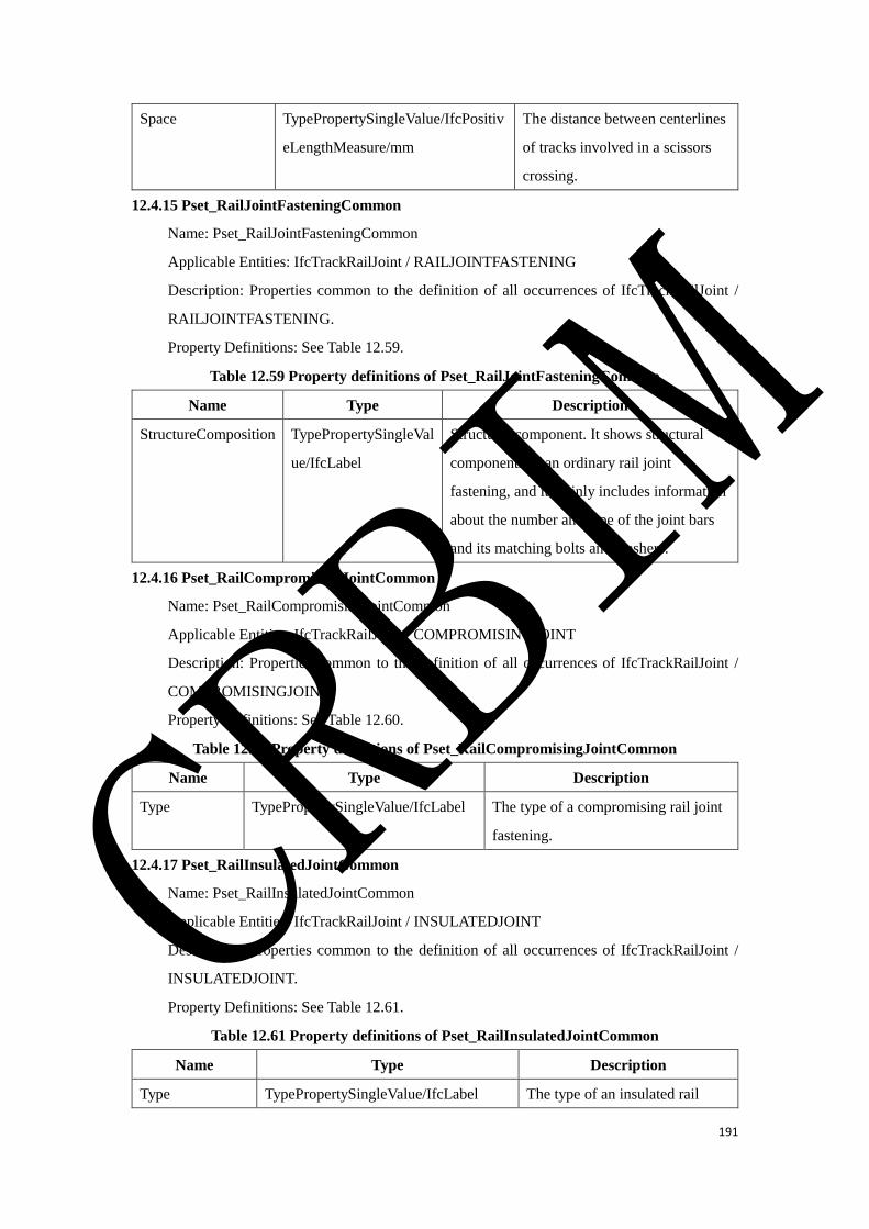
191
Space TypePropertySingleValue/IfcPositiv
eLengthMeasure/mm
The distance between centerlines
of tracks involved in a scissors
crossing.
12.4.15 Pset_RailJointFasteningCommon
Name: Pset_RailJointFasteningCommon
Applicable Entities: IfcTrackRailJoint / RAILJOINTFASTENING
Description: Properties common to the definition of all occurrences of IfcTrackRailJoint /
RAILJOINTFASTENING.
Property Definitions: See Table 12.59.
Table 12.59 Property definitions of Pset_RailJointFasteningCommon
Name Type Description
StructureComposition TypePropertySingleVal
ue/IfcLabel
Structural component. It shows structural
components of an ordinary rail joint
fastening, and it mainly includes information
about the number and type of the joint bars
and its matching bolts and washers.
12.4.16 Pset_RailCompromisingJointCommon
Name: Pset_RailCompromisingJointCommon
Applicable Entities: IfcTrackRailJoint / COMPROMISINGJOINT
Description: Properties common to the definition of all occurrences of IfcTrackRailJoint /
COMPROMISINGJOINT.
Property Definitions: See Table 12.60.
Table 12.60 Property definitions of Pset_RailCompromisingJointCommon
Name Type Description
Type TypePropertySingleValue/IfcLabel The type of a compromising rail joint
fastening.
12.4.17 Pset_RailInsulatedJointCommon
Name: Pset_RailInsulatedJointCommon
Applicable Entities: IfcTrackRailJoint / INSULATEDJOINT
Description: Properties common to the definition of all occurrences of IfcTrackRailJoint /
INSULATEDJOINT.
Property Definitions: See Table 12.61.
Table 12.61 Property definitions of Pset_RailInsulatedJointCommon
Name Type Description
Type TypePropertySingleValue/IfcLabel The type of an insulated rail
CRBIM
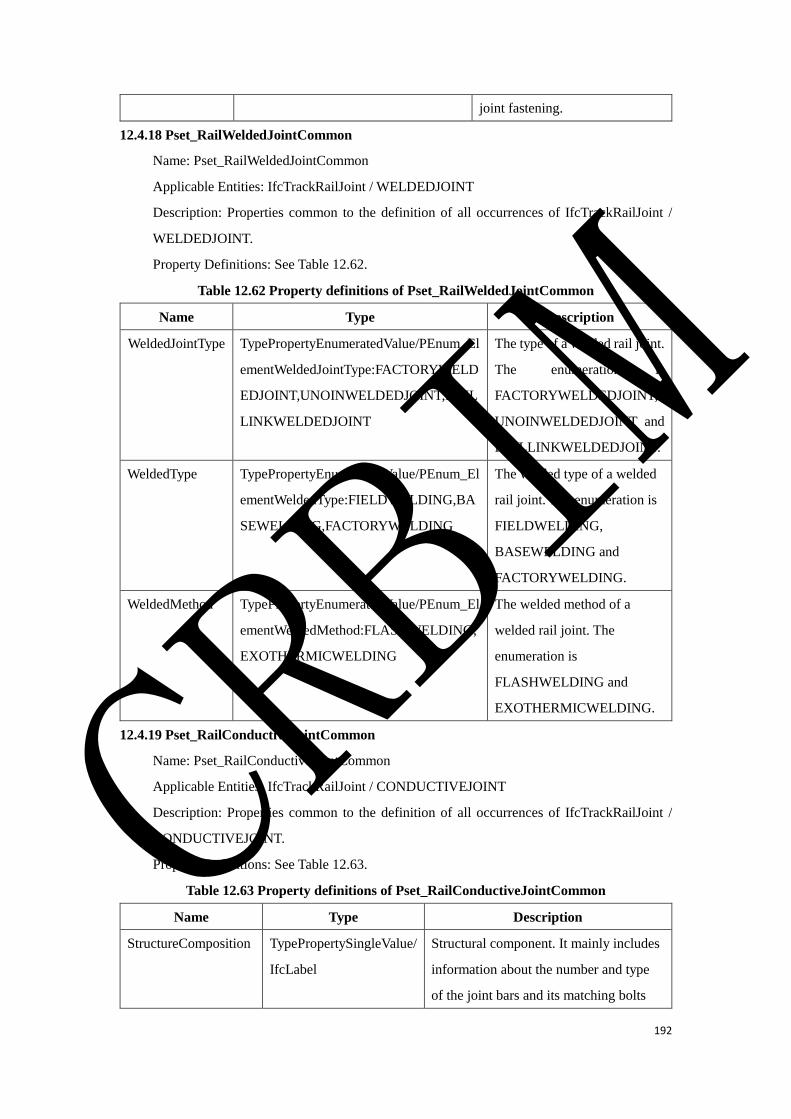
192
joint fastening.
12.4.18 Pset_RailWeldedJointCommon
Name: Pset_RailWeldedJointCommon
Applicable Entities: IfcTrackRailJoint / WELDEDJOINT
Description: Properties common to the definition of all occurrences of IfcTrackRailJoint /
WELDEDJOINT.
Property Definitions: See Table 12.62.
Table 12.62 Property definitions of Pset_RailWeldedJointCommon
Name Type Description
WeldedJointType TypePropertyEnumeratedValue/PEnum_El
ementWeldedJointType:FACTORYWELD
EDJOINT,UNOINWELDEDJOINT,RAIL
LINKWELDEDJOINT
The type of a welded rail joint.
The enumeration is
FACTORYWELDEDJOINT,
UNOINWELDEDJOINT and
RAILLINKWELDEDJOINT.
WeldedType TypePropertyEnumeratedValue/PEnum_El
ementWeldedType:FIELDWELDING,BA
SEWELDING,FACTORYWELDING
The welded type of a welded
rail joint. The enumeration is
FIELDWELDING,
BASEWELDING and
FACTORYWELDING.
WeldedMethod TypePropertyEnumeratedValue/PEnum_El
ementWeldedMethod:FLASHWELDING,
EXOTHERMICWELDING
The welded method of a
welded rail joint. The
enumeration is
FLASHWELDING and
EXOTHERMICWELDING.
12.4.19 Pset_RailConductiveJointCommon
Name: Pset_RailConductiveJointCommon
Applicable Entities: IfcTrackRailJoint / CONDUCTIVEJOINT
Description: Properties common to the definition of all occurrences of IfcTrackRailJoint /
CONDUCTIVEJOINT.
Property Definitions: See Table 12.63.
Table 12.63 Property definitions of Pset_RailConductiveJointCommon
Name Type Description
StructureComposition TypePropertySingleValue/
IfcLabel
Structural component. It mainly includes
information about the number and type
of the joint bars and its matching bolts
CRBIM
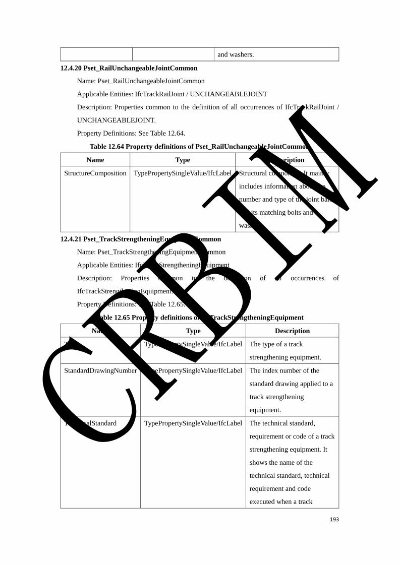
193
and washers.
12.4.20 Pset_RailUnchangeableJointCommon
Name: Pset_RailUnchangeableJointCommon
Applicable Entities: IfcTrackRailJoint / UNCHANGEABLEJOINT
Description: Properties common to the definition of all occurrences of IfcTrackRailJoint /
UNCHANGEABLEJOINT.
Property Definitions: See Table 12.64.
Table 12.64 Property definitions of Pset_RailUnchangeableJointCommon
Name Type Description
StructureComposition TypePropertySingleValue/IfcLabel Structural component. It mainly
includes information about the
number and type of the joint bars
and its matching bolts and
washers.
12.4.21 Pset_TrackStrengtheningEquipmentCommon
Name: Pset_TrackStrengtheningEquipmentCommon
Applicable Entities: IfcTrackStrengtheningEquipment
Description: Properties common to the definition of all occurrences of
IfcTrackStrengtheningEquipment.
Property Definitions: See Table 12.65.
Table 12.65 Property definitions of IfcTrackStrengtheningEquipment
Name Type Description
Type TypePropertySingleValue/IfcLabel The type of a track
strengthening equipment.
StandardDrawingNumber TypePropertySingleValue/IfcLabel The index number of the
standard drawing applied to a
track strengthening
equipment.
TechnicalStandard TypePropertySingleValue/IfcLabel The technical standard,
requirement or code of a track
strengthening equipment. It
shows the name of the
technical standard, technical
requirement and code
executed when a track
CRBIM
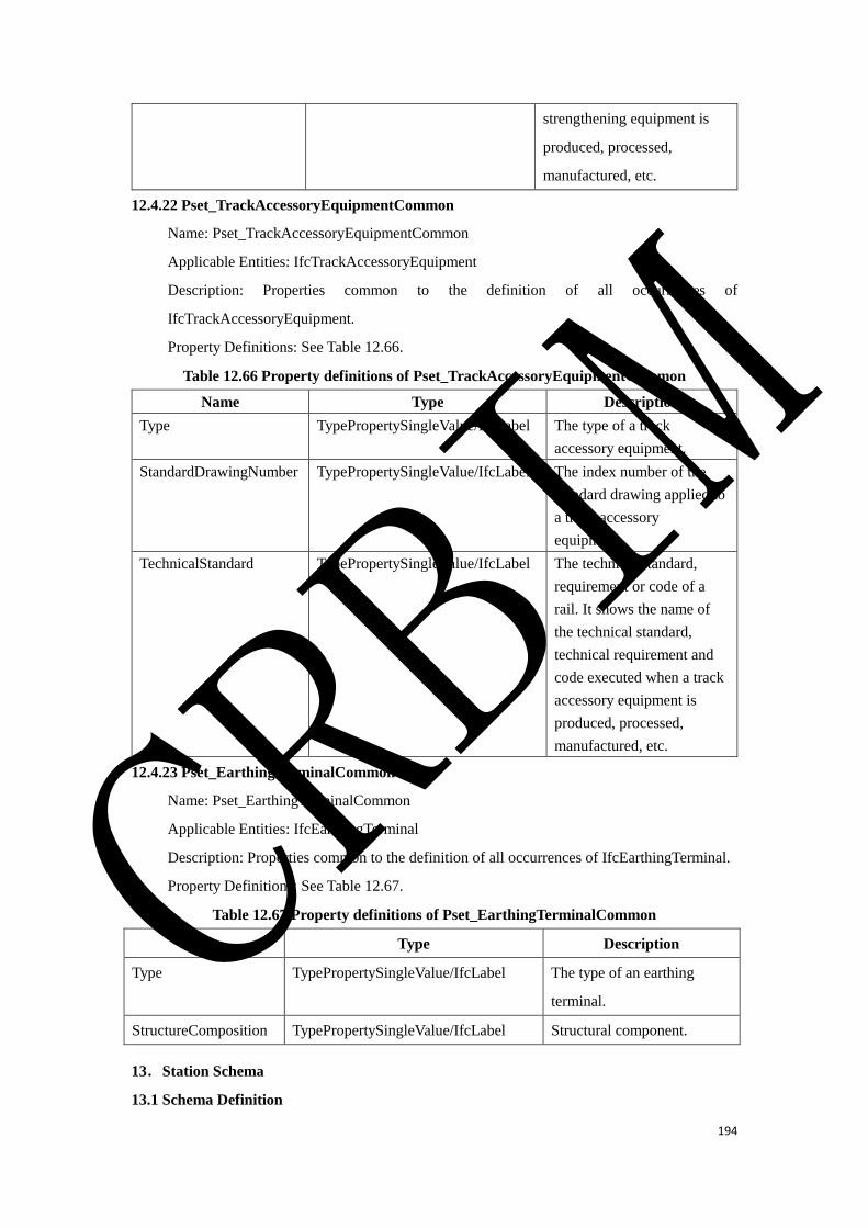
194
strengthening equipment is
produced, processed,
manufactured, etc.
12.4.22 Pset_TrackAccessoryEquipmentCommon
Name: Pset_TrackAccessoryEquipmentCommon
Applicable Entities: IfcTrackAccessoryEquipment
Description: Properties common to the definition of all occurrences of
IfcTrackAccessoryEquipment.
Property Definitions: See Table 12.66.
Table 12.66 Property definitions of Pset_TrackAccessoryEquipmentCommon
Name Type Description
Type TypePropertySingleValue/IfcLabel The type of a track
accessory equipment.
StandardDrawingNumber TypePropertySingleValue/IfcLabel The index number of the
standard drawing applied to
a track accessory
equipment.
TechnicalStandard TypePropertySingleValue/IfcLabel The technical standard,
requirement or code of a
rail. It shows the name of
the technical standard,
technical requirement and
code executed when a track
accessory equipment is
produced, processed,
manufactured, etc.
12.4.23 Pset_EarthingTerminalCommon
Name: Pset_EarthingTerminalCommon
Applicable Entities: IfcEarthingTerminal
Description: Properties common to the definition of all occurrences of IfcEarthingTerminal.
Property Definitions: See Table 12.67.
Table 12.67 Property definitions of Pset_EarthingTerminalCommon
Name Type Description
Type TypePropertySingleValue/IfcLabel The type of an earthing
terminal.
StructureComposition TypePropertySingleValue/IfcLabel Structural component.
13.Station Schema
13.1 Schema Definition
CRBIM
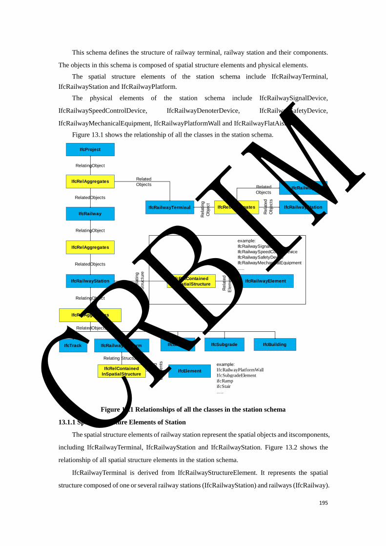
195
This schema defines the structure of railway terminal, railway station and their components.
The objects in this schema is composed of spatial structure elements and physical elements.
The spatial structure elements of the station schema include IfcRailwayTerminal,
IfcRailwayStation and IfcRailwayPlatform.
The physical elements of the station schema include IfcRailwaySignalDevice,
IfcRailwaySpeedControlDevice, IfcRailwayDenoterDevice, IfcRailwaySafetyDevice,
IfcRailwayMechanicalEquipment, IfcRailwayPlatformWall and IfcRailwayFlatAisle.
Figure 13.1 shows the relationship of all the classes in the station schema.
Figure 13.1 Relationships of all the classes in the station schema
13.1.1 Spatial Structure Elements of Station
The spatial structure elements of railway station represent the spatial objects and itscomponents,
including IfcRailwayTerminal, IfcRailwayStation and IfcRailwayStation. Figure 13.2 shows the
relationship of all spatial structure elements in the station schema.
IfcRailwayTerminal is derived from IfcRailwayStructureElement. It represents the spatial
structure composed of one or several railway stations (IfcRailwayStation) and railways (IfcRailway).
IfcProject
IfcRailway
IfcRailwayStation
IfcRelAggregates
IfcRelAggregates
RelatingObject
RelatedObjects
IfcRelContained
InSpatialStructureIfcRailwayElement
RelatingObject
RelatedObjects
Rela
ting
Str
uctu
re
Rela
ted
Ele
ments
example:
IfcRailwaySignalDevice
IfcRailwaySpeedControlDevice
IfcRailwaySafetyDevice
IfcRailwayMechanicalEquipment
.....
IfcTrack
IfcRelAggregates
RelatingObject
RelatedObjects
IfcRailwayPlatform
IfcRailwayTerminal
IfcSubgradeIfcBridge IfcBuilding
IfcRelContained
InSpatialStructure
Relating Structure
IfcElement
Rela
ted
Ele
ments example:
IfcRailwayPlatformWall
IfcSubgradeElement
ifcRamp
ifcStair
.....
IfcRelAggregates IfcRailwayStation
Rela
ting
Obje
ct
Rela
ted
Obje
cts
IfcRailwayRelated
Objects
Related
Objects
CRBIM
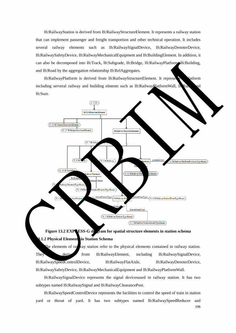
196
IfcRailwayStation is derived from IfcRailwayStructureElement. It represents a railway station
that can implement passenger and freight transportion and other technical operation. It includes
several railway elements such as IfcRailwaySignalDevice, IfcRailwayDenoterDevice,
IfcRailwaySafetyDevice, IfcRailwayMechanicalEquipment and IfcBuildingElement. In addition, it
can also be decomposed into IfcTrack, IfcSubgrade, IfcBridge, IfcRailwayPlatform, IfcBuilding,
and IfcRoad by the aggregation relationship IfcRelAggregates.
IfcRailwayPlatform is derived from IfcRailwayStructureElement. It represents a platform
including serveral railway and building elments such as IfcRailwayPlatformWall, IfcRamp and
IfcStair.
Figure 13.2 EXPRESS-G diagram for spatial structure elements in station schema
13.1.2 Physical Elements in Station Schema
The elements of railway station refer to the physical elements contained in railway station.
They are derived from IfcRailwayElement, including IfcRailwaySignalDevice,
IfcRailwaySpeedControlDevice, IfcRailwayFlatAisle, IfcRailwayDenoterDevice,
IfcRailwaySafetyDevice, IfcRailwayMechanicalEquipment and IfcRailwayPlatformWall.
IfcRailwaySignalDevice represents the signal devicesused in railway station. It has two
subtypes named IfcRailwaySignal and IfcRailwayClearancePost.
IfcRailwaySpeedControlDevice represents the facilities to control the speed of train in station
yard or throat of yard. It has two subtypes named IfcRailwaySpeedReducer and
CRBIM
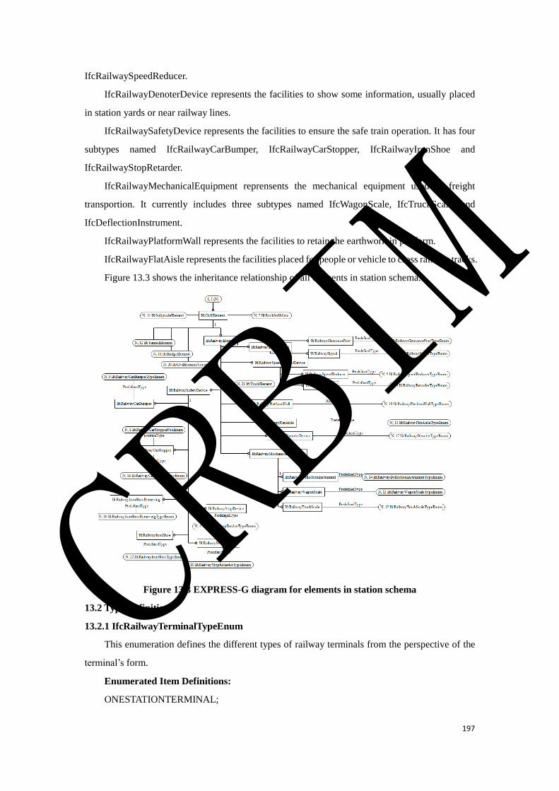
197
IfcRailwaySpeedReducer.
IfcRailwayDenoterDevice represents the facilities to show some information, usually placed
in station yards or near railway lines.
IfcRailwaySafetyDevice represents the facilities to ensure the safe train operation. It has four
subtypes named IfcRailwayCarBumper, IfcRailwayCarStopper, IfcRailwayIronShoe and
IfcRailwayStopRetarder.
IfcRailwayMechanicalEquipment reprensents the mechanical equipment used in freight
transportion. It currently includes three subtypes named IfcWagonScale, IfcTruckScale, and
IfcDeflectionInstrument.
IfcRailwayPlatformWall represents the facilities to retain the earthwork in platform.
IfcRailwayFlatAisle represents the facilities placed for people or vehicle to cross railway tracks.
Figure 13.3 shows the inheritance relationship of all elements in station schema.
Figure 13.3 EXPRESS-G diagram for elements in station schema
13.2 Type Definition
13.2.1 IfcRailwayTerminalTypeEnum
This enumeration defines the different types of railway terminals from the perspective of the
terminal’s form.
Enumerated Item Definitions:
ONESTATIONTERMINAL;
CRBIM
198
TRIANGLETERMINAL;
LINEARTERMINAL;
CROSSTERMINAL;
PARALLELTERMINAL;
RINGLIKETERMINAL;
MAKEENDTERMINAL;
COMBINEDTERMINAL;
USERDEFINED;
NOTDEFINED.
EXPRESS Specification:
TYPE IfcRailwayTerminalTypeEnum = ENUMERATION OF
(ONESTATIONTERMINAL
,TRIANGLETERMINAL
,LINEARTERMINAL
,CROSSTERMINAL
,PARALLELTERMINAL
,RINGLIKETERMINAL
,MAKEENDTERMINAL
,COMBINEDTERMINAL
,USERDEFINED
,NOTDEFINED
);
END_TYPE;
13.2.2 IfcRailwayTerminalFeatureTypeEnum
This enumeration defines the different types of railway terminals from the perspective of the
terminal’s function.
Enumerated Item Definitions:
NETWORKTERMINAL;
REGIONALTERMINAL;
LOCALTERMINAL;
USERDEFINED;
NOTDEFINED.
EXPRESS Specification:
TYPE IfcRailwayTerminalFeatureTypeEnum = ENUMERATION OF
(NETWORKTERMINAL
,REGIONALTERMINAL
,LOCALTERMINAL
CRBIM
199
,USERDEFINED
,NOTDEFINED
);
END_TYPE;
13.2.3 IfcRailwayStationTypeEnum
IfcRailwayStationTypeEnum defines the different types of railway stations from the
perspective of the station’s technical operation.
Enumerated Item Definitions:
INTERMEDIATESTATION;
DISTRICTSTATION;
MARSHALLINGSTATION;
PASSINGSTATION;
OVERTAKINGSTATION;
HALTSTATION: Halt station.
BLOCKPOST;
USERDEFINED;
NOTDEFINED.
EXPRESS Specification:
TYPE IfcRailwayStationTypeEnum = ENUMERATION OF
(INTERMEDIATESTATION
,DISTRICTSTATION
,MARSHALLINGSTATION
,PASSINGSTATION
,OVERTAKINGSTATION
,HALTSTATION
,BLOCKPOST
,USERDEFINED
,NOTDEFINED
);
END_TYPE;
13.2.4 IfcRailwayStationFeatureTypeEnum
IfcRailwayStationFeatureTypeEnum defines the different types of railway stations from the
perspective of the station’s function.
Enumerated Item Definitions:
PASSENGERSTATION;
FREIGHTSTATION;
PASSENGERANDFREIGHTSTATION;
USERDEFINED;
CRBIM
200
NOTDEFINED.
EXPRESS Specification:
TYPE IfcRailwayStationFeatureTypeEnum = ENUMERATION OF
(PASSENGERSTATION
,FREIGHTSTATION
,PASSENGERANDFREIGHTSTATION
,USERDEFINED
,NOTDEFINED
);
END_TYPE;
13.2.5 IfcRailwayStationFormTypeEnum
IfcRailwayStationFormTypeEnum defines the different types of railway stations from the
perspective of the station’s form.
Enumerated Item Definitions:
TRANSVERSEARRANGEMENT;
LONGITUDINALARRANGMENT;
MIXEDARRANGMENT;
USERDEFINED;
NOTDEFINED.
EXPRESS Specification:
TYPE IfcRailwayStationFormTypeEnum = ENUMERATION OF
(TRANSVERSEARRANGEMENT
,LONGITUDINALARRANGMENT
,MIXEDARRANGMENT
,USERDEFINED
,NOTDEFINED
);
END_TYPE;
13.2.6 IfcRailwayStationGradeTypeEnum
IfcRailwayStationGradeTypeEnum defines the different types of railway stations from the
perspective of the station’s grade.
Enumerated Item Definitions:
GRADESUPER;
GRADEFIRST;
GRADESECOND;
GRADETHIRD;
GRADEFOURTH;
CRBIM

201
GRADEFIFTH;
USERDEFINED;
NOTDEFINED.
EXPRESS Specification:
TYPE IfcRailwayStationGradeTypeEnum = ENUMERATION OF
(GRADESUPER
,GRADEFIRST
,GRADESECOND
,GRADETHIRD
,GRADEFOURTH
,GRADEFIFTH
,USERDEFINED
,NOTDEFINED
);
END_TYPE;
13.2.7 IfcRailwayPlatformTypeEnum
IfcRailwayPlatformTypeEnum defines the different types of station platforms from the
perspective of the platform’s function.
Enumerated Item Definitions:
PASSENGERPLATFORM;
FREIGHTPLATFORM;
USERDEFINED;
NOTDEFINED.
EXPRESS Specification:
TYPE IfcRailwayPlatformTypeEnum = ENUMERATION OF
(PASSENGERPLATFORM
,FREIGHTPLATFORM
,USERDEFINED
,NOTDEFINED
);
END_TYPE;
13.2.8 IfcRailwayPlatformPositionTypeEnum
IfcRailwayPlatformPositionTypeEnum defines the different types of station platforms from the
perspective of the platform’s position.
Enumerated Item Definitions:
INTERMEDIATEPLATFORM;
BASICPLATFORM;
ENDTYPEPLATFORM;
CRBIM

202
USERDEFINED;
NOTDEFINED.
EXPRESS Specification:
TYPE IfcRailwayPlatformPositionTypeEnum = ENUMERATION OF
(INTERMEDIATEPLATFORM
,BASICPLATFORM
,ENDTYPEPLATFORM
,USERDEFINED
,NOTDEFINED
);
END_TYPE;
13.2.9 IfcRailwaySignalTypeEnum
IfcRailwaySignalTypeEnum defines the different types of signals from the perspective of the
signal’s function.
Enumerated Item Definitions:
STARTINGSIGNAL;
HOMESIGNAL;
ROUTESIGNAL;
SHUNTINGSIGNAL;
HUMPSIGNAL;
BLOCKSIGNAL;
DISTANTSIGNAL;
APPROACHSIGNAL;
REPEATINGSIGNAL;
USERDEFINED;
NOTDEFINED.
EXPRESS Specification:
TYPE IfcRailwaySignalTypeEnum = ENUMERATION OF
(STARTINGSIGNAL
,HOMESIGNAL
,ROUTESIGNAL
,SHUNTINGSIGNAL
,HUMPSIGNAL
,BLOCKSIGNAL
,DISTANTSIGNAL
,APPROACHSIGNAL
,REPEATINGSIGNAL
,USERDEFINED
CRBIM

203
,NOTDEFINED
);
END_TYPE;
13.2.10 IfcRailwayClearancePostTypeEnum
IfcRailwayClearancePostTypeEnum defines the different types of clearance posts from the
perspective of the clearance post’s function.
Enumerated Item Definitions:
USERDEFINED;
NOTDEFINED.
EXPRESS Specification:
TYPE IfcRailwayClearancePostTypeEnum = ENUMERATION OF
(USERDEFINED
,NOTDEFINED
);
END_TYPE;
13.2.11 IfcRailwaySpeedReducerTypeEnum
IfcRailwaySpeedReducerTypeEnum defines the different types of speed reducers from the
perspective of the speed reducer’s operation type.
Enumerated Item Definitions:
WINDPRESSURECLAMP;
WINDPRESSUREGRAVITY;
USERDEFINED;
NOTDEFINED.
EXPRESS Specification:
TYPE IfcRailwaySpeedReducerTypeEnum = ENUMERATION OF
(WINDPRESSURECLAMP
,WINDPRESSUREGRAVITY
,USERDEFINED
,NOTDEFINED
);
END_TYPE;
13.2.12 IfcRailwayRetarderTypeEnum
IfcRailwayRetarderTypeEnum defines the different types of railway retarders from the
perspective of the railway retarder’s operation type.
Enumerated Item Definitions:
COMMONRETARDER;
CONTROLLABLEDRETARDER;
CRBIM

204
USERDEFINED;
NOTDEFINED.
EXPRESS Specification:
TYPE IfcRailwayRetarderTypeEnum = ENUMERATION OF
(COMMONRETARDER
,CONTROLLABLEDRETARDER
,USERDEFINED
,NOTDEFINED
);
END_TYPE;
13.2.13 IfcRailwayDenoterTypeEnum
IfcRailwayDenoterTypeEnum defines the different types of denoters from the perspective of
the denoter’s function.
Enumerated Item Definitions:
BOUNDARYSIGN;
PARKINGSIGN;
SAFETYSIGN;
LANDMARKSIGN;
CROSSINGALERTSIGN;
ROUTESIGN;
SIGNALSIGN;
DISPLACEMENTOBSERVATIONPEG;
USERDEFINED;
NOTDEFINED.
EXPRESS Specification:
TYPE IfcRailwayDenoterTypeEnum = ENUMERATION OF
(BOUNDARYSIGN
,PARKINGSIGN
,SAFETYSIGN
,LANDMARKSIGN
,CROSSINGALERTSIGN
,ROUTESIGN
,SIGNALSIGN
,DISPLACEMENTOBSERVATIONPEG
,USERDEFINED
,NOTDEFINED
);
END_TYPE;
CRBIM
205
13.2.14 IfcRailwayCarBumperTypeEnum
IfcRailwayCarBumperTypeEnum defines the different types of car bumpers from the
perspective of the car bumper’s pattern.
Enumerated Item Definitions:
MOUNDTYPE;
MORTARRUBBLETYPE;
CURVEDTYPEA;
CURVEDTYPEB;
USERDEFINED;
NOTDEFINED.
EXPRESS Specification:
TYPE IfcRailwayCarBumperTypeEnum = ENUMERATION OF
(MOUNDTYPE
,MORTARRUBBLETYPE
,CURVEDTYPEA
,CURVEDTYPEB
,USERDEFINED
,NOTDEFINED
);
END_TYPE;
13.2.15 IfcRailwayCarStopperTypeEnum
IfcRailwayCarStopperTypeEnum defines the different types of car stoppers from the
perspective of the car stopper’s pattern.
Enumerated Item Definitions:
FIXEDSTOPPER;
SLIDESTOPPER;
USERDEFINED;
NOTDEFINED.
EXPRESS Specification:
TYPE IfcRailwayCarStopperTypeEnum = ENUMERATION OF
(FIXEDSTOPPER
,SLIDESTOPPER
,USERDEFINED
,NOTDEFINED
);
END_TYPE;
13.2.16 IfcRailwayCarStopperPostionTypeEnum
CRBIM
206
IfcRailwayCarStopperPostionTypeEnum defines the different types of car stoppers from the
perspective of the car stopper’s position.
Enumerated Item Definitions:
INSIDETYPE;
OUTSIDETYPE;
USERDEFINED;
NOTDEFINED.
EXPRESS Specification:
TYPE IfcRailwayCarStopperPostionTypeEnum = ENUMERATION OF
(INSIDETYPE
,OUTSIDETYPE
,NOTDEFINED
,USERDEFINED
);
END_TYPE;
13.2.17 IfcRailwayPlatformWallTypeEnum
IfcRailwayPlatformWallTypeEnum defines the different types of platform walls from the
perspective of the platform wall’s pattern.
Enumerated Item Definitions:
STRAIGHTWALL;
INCLINEDWALL;
USERDEFINED;
NOTDEFINED.
EXPRESS Specification:
TYPE IfcRailwayPlatformWallTypeEnum = ENUMERATION OF
(STRAIGHTWALL
,INCLINEDWALL
,USERDEFINED
,NOTDEFINED
);
END_TYPE;
13.2.18 IfcRailwayFlatAisleTypeEnum
IfcRailwayFlatAisleTypeEnum defines the different types of flat aisles from the perspective of
the flat aisle’s function.
Enumerated Item Definitions:
USERDEFINED;
NOTDEFINED.
CRBIM

207
EXPRESS Specification:
TYPE IfcRailwayFlatAisleTypeEnum = ENUMERATION OF
(USERDEFINED
,NOTDEFINED
);
END_TYPE;
13.2.19 IfcRailwayWagonScaleTypeEnum
IfcRailwayWagonScaleTypeEnum defines the different types of wagon scales from the
perspective of the wagon scale’s function.
Enumerated Item Definitions:
USERDEFINED;
NOTDEFINED.
EXPRESS Specification:
TYPE IfcRailwayWagonScaleTypeEnum = ENUMERATION OF
(USERDEFINED
,NOTDEFINED
);
END_TYPE;
13.2.20 IfcRailwayDeflectionInstrumentTypeEnum
IfcRailwayDeflectionInstrumentTypeEnum defines the different types of deflection
instruments from the perspective of the deflection instrument’s function.
Enumerated Item Definitions:
USERDEFINED;
NOTDEFINED.
EXPRESS Specification:
TYPE IfcRailwayDeflectionInstrumentTypeEnum = ENUMERATION OF
(USERDEFINED
,NOTDEFINED
);
END_TYPE;
13.2.21 IfcRailwayIronShoeRemovingTypeEnum
IfcRailwayIronShoeRemovingTypeEnum defines the type of Iron Shoe Removing from the
perspective of the Iron Shoe Removing’s function.
Enumerated Item Definitions:
USERDEFINED;
NOTDEFINED.
CRBIM

208
EXPRESS Specification:
TYPE IfcRailwayIronShoeRemovingTypeEnum = ENUMERATION OF
(USERDEFINED
,NOTDEFINED
);
END_TYPE;
13.2.22 IfcRailwayStopDeviceTypeEnum
IfcRailwayStopDeviceTypeEnum defines the type of railway stop device from the perspective
of the railway stop device’s function.
Enumerated Item Definitions:
USERDEFINED;
NOTDEFINED.
EXPRESS Specification:
TYPE IfcRailwayStopDeviceTypeEnum = ENUMERATION OF
(USERDEFINED
,NOTDEFINED
);
END_TYPE;
13.2.23 IfcRailwayStopRetarderTypeEnum
IfcRailwayStopRetarderTypeEnum defines the type of railway stop retarder from the
perspective of function.
Enumerated Item Definitions:
USERDEFINED;
NOTDEFINED.
EXPRESS Specification:
TYPE IfcRailwayStopRetarderTypeEnum = ENUMERATION OF
(USERDEFINED
,NOTDEFINED
);
END_TYPE;
13.2.24 IfcRailwayIronShoeTypeEnum
IfcRailwayIronShoeTypeEnum defines the type of railway iron shoes from the perspective of
the function.
Enumerated Item Definitions:
USERDEFINED;
NOTDEFINED.
CRBIM
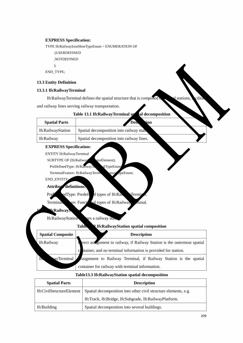
209
EXPRESS Specification:
TYPE IfcRailwayIronShoeTypeEnum = ENUMERATION OF
(USERDEFINED
,NOTDEFINED
);
END_TYPE;
13.3 Entity Definition
13.3.1 IfcRailwayTerminal
IfcRailwayTerminal defines the spatial structure that is composed of several stations, facilities
and railway lines serving railway transportation.
Table 13.1 IfcRailwayTerminal spatial decomposition
Spatial Parts Description
IfcRailwayStation Spatial decomposition into railway stations.
IfcRailway Spatial decomposition into railway lines.
EXPRESS Specification:
ENTITY IfcRailwayTerminal
SUBTYPE OF (IfcRailwayStructureElement);
PreDefinedType: IfcRailwayTerminalTypeEnum;
TerminalFeature: IfcRailwayTerminalFeatureTypeEnum;
END_ENTITY;
Attribute definitions:
PreDefinedType: Predefined types of IfcRailwayTerminal.
TerminalFeature: Functional types of IfcRailwayTerminal.
13.3.2 IfcRailwayStation
IfcRailwayStation defines a railway station.
Table 13.2 IfcRailwayStation spatial composition
Spatial Composite Description
IfcRailway Direct assignment to railway, if Railway Station is the outermost spatial
container, and no terminal information is provided for station.
IfcRailwayTerminal Assignment to Railway Terminal, if Railway Station is the spatial
container for railway with terminal information.
Table13.3 IfcRailwayStation spatial decomposition
Spatial Parts Description
IfcCivilStructureElement Spatial decomposition into other civil structure elements, e.g.
IfcTrack, IfcBridge, IfcSubgrade, IfcRailwayPlatform.
IfcBuilding Spatial decomposition into several buildings.
CRBIM
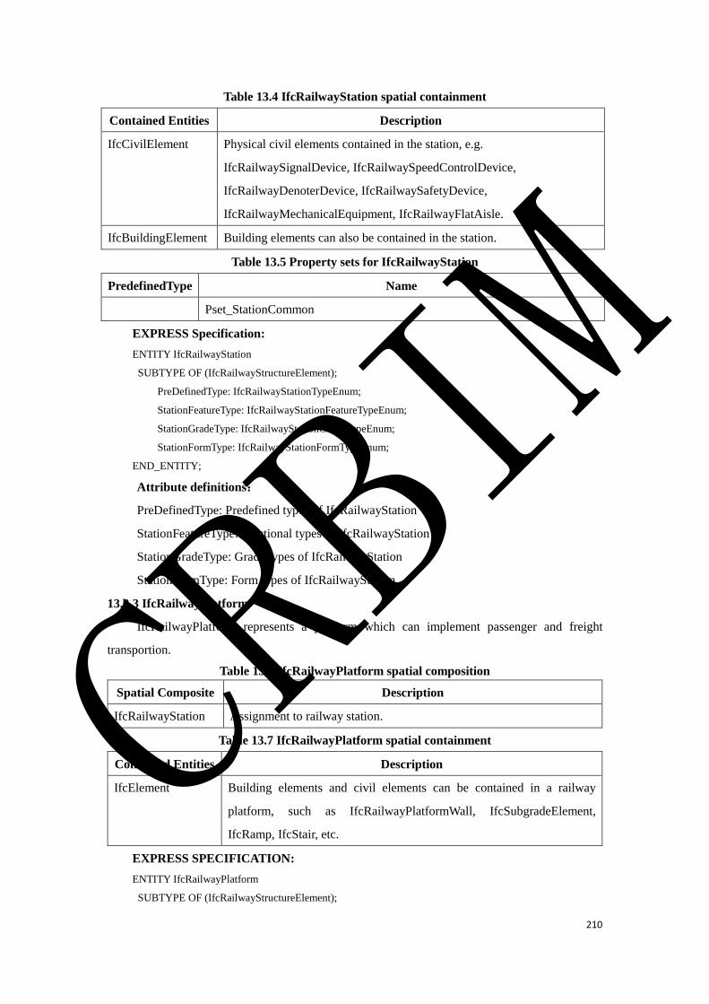
210
Table 13.4 IfcRailwayStation spatial containment
Contained Entities Description
IfcCivilElement Physical civil elements contained in the station, e.g.
IfcRailwaySignalDevice, IfcRailwaySpeedControlDevice,
IfcRailwayDenoterDevice, IfcRailwaySafetyDevice,
IfcRailwayMechanicalEquipment, IfcRailwayFlatAisle.
IfcBuildingElement Building elements can also be contained in the station.
Table 13.5 Property sets for IfcRailwayStation
PredefinedType Name
Pset_StationCommon
EXPRESS Specification:
ENTITY IfcRailwayStation
SUBTYPE OF (IfcRailwayStructureElement);
PreDefinedType: IfcRailwayStationTypeEnum;
StationFeatureType: IfcRailwayStationFeatureTypeEnum;
StationGradeType: IfcRailwayStationGradeTypeEnum;
StationFormType: IfcRailwayStationFormTypeEnum;
END_ENTITY;
Attribute definitions:
PreDefinedType: Predefined types of IfcRailwayStation
StationFeatureType: functional types of IfcRailwayStation
StationGradeType: Grade types of IfcRailwayStation
StationFormType: Form types of IfcRailwayStation
13.3.3 IfcRailwayPlatform
IfcRailwayPlatform represents a platform which can implement passenger and freight
transportion.
Table 13.6 IfcRailwayPlatform spatial composition
Spatial Composite Description
IfcRailwayStation Assignment to railway station.
Table 13.7 IfcRailwayPlatform spatial containment
Contained Entities Description
IfcElement Building elements and civil elements can be contained in a railway
platform, such as IfcRailwayPlatformWall, IfcSubgradeElement,
IfcRamp, IfcStair, etc.
EXPRESS SPECIFICATION:
ENTITY IfcRailwayPlatform
SUBTYPE OF (IfcRailwayStructureElement);
CRBIM
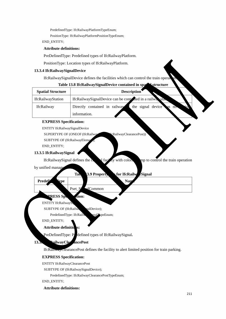
211
PredefinedType: IfcRailwayPlatformTypeEnum;
PositionType: IfcRailwayPlatformPositionTypeEnum;
END_ENTITY;
Attribute definitions:
PreDefinedType: Predefined types of IfcRailwayPlatform.
PositionType: Location types of IfcRailwayPlatform.
13.3.4 IfcRailwaySignalDevice
IfcRailwaySignalDevice defines the facilities which can control the train operation.
Table 13.8 IfcRailwaySignalDevice contained in spatial structure
Spatial Structure Description
IfcRailwayStation IfcRailwaySignalDevice can be contained in a railway station.
IfcRailway Directly contained in railway, if the signal device has no station
information.
EXPRESS Specification:
ENTITY IfcRailwaySignalDevice
SUPERTYPE OF (ONEOF (IfcRailwaySignal, IfcRailwayClearancePost))
SUBTYPE OF (IfcRailwayElement);
END_ENTITY;
13.3.5 IfcRailwaySignal
IfcRailwaySignal defines the control facility with colorful lamp to control the train operation
by unified management.
Table 13.9 Property sets for IfcRailwaySignal
PredefinedType Name
Pset_SignalCommon
EXPRESS Specification:
ENTITY IfcRailwaySignal
SUBTYPE OF (IfcRailwaySignalDevice);
PredefinedType: IfcRailwaySignalTypeEnum;
END_ENTITY;
Attribute definitions:
PreDefinedType: Predefined types of IfcRailwaySignal.
13.3.6 IfcRailwayClearancePost
IfcRailwayClearancePost defines the facility to alert limited position for train parking.
EXPRESS Specification:
ENTITY IfcRailwayClearancePost
SUBTYPE OF (IfcRailwaySignalDevice);
PredefinedType: IfcRailwayClearancePostTypeEnum;
END_ENTITY;
Attribute definitions:
CRBIM
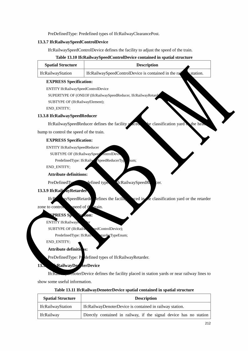
212
PreDefinedType: Predefined types of IfcRailwayClearancePost.
13.3.7 IfcRailwaySpeedControlDevice
IfcRailwaySpeedControlDevice defines the facility to adjust the speed of the train.
Table 13.10 IfcRailwaySpeedControlDevice contained in spatial structure
Spatial Structure Description
IfcRailwayStation IfcRailwaySpeedControlDevice is contained in the railway station.
EXPRESS Specification:
ENTITY IfcRailwaySpeedControlDevice
SUPERTYPE OF (ONEOF (IfcRailwaySpeedReducer, IfcRailwayRetarder))
SUBTYPE OF (IfcRailwayElement);
END_ENTITY;
13.3.8 IfcRailwaySpeedReducer
IfcRailwaySpeedReducer defines the facility placed in the classification yard or the head of
hump to control the speed of the train.
EXPRESS Specification:
ENTITY IfcRailwaySpeedReducer
SUBTYPE OF (IfcRailwaySpeedControlDevice);
PredefinedType: IfcRailwaySpeedReducerTypeEnum;
END_ENTITY;
Attribute definitions:
PreDefinedType:Predefined types of IfcRailwaySpeedReducer.
13.3.9 IfcRailwayRetarder
IfcRailwaySpeedRetarder defines the facility placed in the classification yard or the retarder
zone to control the speed of the train.
EXPRESS Specification:
ENTITY IfcRailwayRetarder
SUBTYPE OF (IfcRailwaySpeedControlDevice);
PredefinedType: IfcRailwayRetarderTypeEnum;
END_ENTITY;
Attribute definitions:
PreDefinedType: Predefined types of IfcRailwayRetarder.
13.3.10 IfcRailwayDenoterDevice
IfcRailwayDenoterDevice defines the facility placed in station yards or near railway lines to
show some useful information.
Table 13.11 IfcRailwayDenoterDevice spatial contained in spatial structure
Spatial Structure Description
IfcRailwayStation IfcRailwayDenoterDevice is contained in railway station.
IfcRailway Directly contained in railway, if the signal device has no station
CRBIM
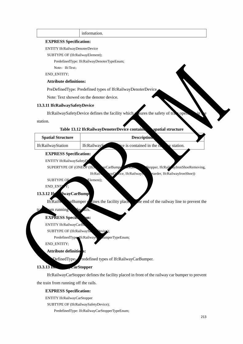
213
information.
EXPRESS Specification:
ENTITY IfcRailwayDenoterDevice
SUBTYPE OF (IfcRailwayElement);
PredefinedType: IfcRailwayDenoterTypeEnum;
Note:IfcText;
END_ENTITY;
Attribute definitions:
PreDefinedType: Predefined types of IfcRailwayDenoterDevice.
Note: Text showed on the denoter device.
13.3.11 IfcRailwaySafetyDevice
IfcRailwaySafetyDevice defines the facility which ensures the safety of train operation in the
station.
Table 13.12 IfcRailwayDenoterDevice contained in spatial structure
Spatial Structure Description
IfcRailwayStation IfcRailwaySafetyDevice is contained in the railway station.
EXPRESS Specification:
ENTITY IfcRailwaySafetyDevice
SUPERTYPE OF (ONEOF (IfcRailwayCarBumper, IfcRailwayCarStopper, IfcRailwayIronShoeRemoving,
IfcRailwayStopDevice, IfcRailwayStopRetarder, IfcRailwayIronShoe))
SUBTYPE OF (IfcRailwayElement);
END_ENTITY;
13.3.12 IfcRailwayCarBumper
IfcRailwayCarBumper defines the facility placed at the end of the railway line to prevent the
train from running off the rails.
EXPRESS Specification:
ENTITY IfcRailwayCarBumper
SUBTYPE OF (IfcRailwaySafetyDevice);
PredefinedType: IfcRailwayCarBumperTypeEnum;
END_ENTITY;
Attribute definitions:
PreDefinedType:Predefined types of IfcRailwayCarBumper.
13.3.13 IfcRailwayCarStopper
IfcRailwayCarStopper defines the facility placed in front of the railway car bumper to prevent
the train from running off the rails.
EXPRESS Specification:
ENTITY IfcRailwayCarStopper
SUBTYPE OF (IfcRailwaySafetyDevice);
PredefinedType: IfcRailwayCarStopperTypeEnum;
CRBIM

214
PositionType: IfcRailwayCarStopperPosTypeEnum;
END_ENTITY;
Attribute definitions:
PreDefinedType: Predefined types of IfcRailwayCarStopper.
PositionType: Position types of IfcRailwayCarStopper.
13.3.14 IfcRailwayIronShoe
IfcRailwayIronShoe defines a kind of safety facility to ensure the train to stop at the proper
position.
EXPRESS Specification:
ENTITY IfcRailwayIronShoe
SUBTYPE OF (IfcRailwaySafetyDevice);
PredefinedType: IfcRailwayIronShoeTypeEnum;
END_ENTITY;
Attribute definitions:
PreDefinedType: Predefined types of IfcRailwayIronShoe.
13.3.15 IfcRailwayStopRetarde
IfcRailwayStopRetarder defines a kind of safety facility to ensure the train to stop at the proper
position.
EXPRESS Specification:
ENTITY IfcRailwayStopRetarder
SUBTYPE OF (IfcRailwaySafetyDevice);
PredefinedType: IfcRailwayStopRetarderTypeEnum;
END_ENTITY;
Attribute definitions:
PreDefinedType: Predefined types of IfcRailwayStopRetarder.
13.3.16 IfcRailwayStopDevice
IfcRailwayStopRetarder defines a kind of safety facility to ensure the train to stop at the proper
position.
EXPRESS Specification:
ENTITY IfcRailwayStopDevice
SUBTYPE OF (IfcRailwaySafetyDevice);
PredefinedType: IfcRailwayStopDeviceTypeEnum;
END_ENTITY;
Attribute definitions:
PreDefinedType: Predefined types of IfcRailwayStopDevice.
13.3.17 IfcRailwayIronShoeRemoving
IfcRailwayIronShoeRemoving defines a kind of safety facility to ensure the iron shoe to fall
off from rails at the proper position.
CRBIM
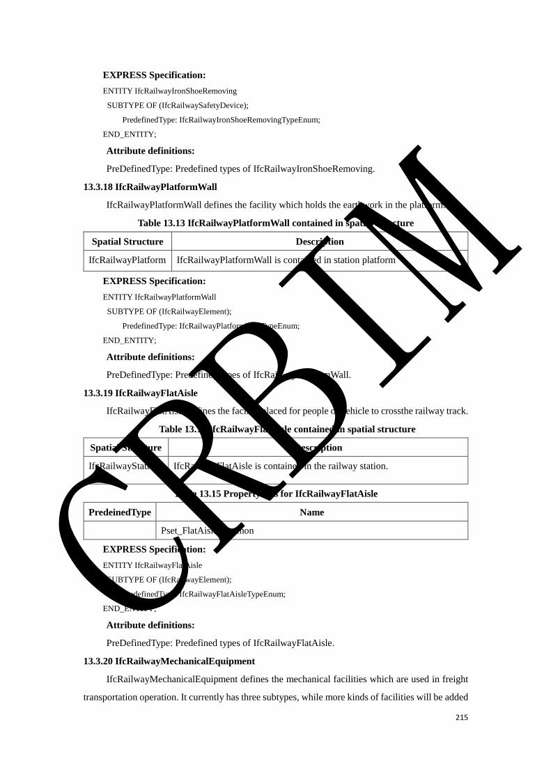
215
EXPRESS Specification:
ENTITY IfcRailwayIronShoeRemoving
SUBTYPE OF (IfcRailwaySafetyDevice);
PredefinedType: IfcRailwayIronShoeRemovingTypeEnum;
END_ENTITY;
Attribute definitions:
PreDefinedType: Predefined types of IfcRailwayIronShoeRemoving.
13.3.18 IfcRailwayPlatformWall
IfcRailwayPlatformWall defines the facility which holds the earthwork in the platform.
Table 13.13 IfcRailwayPlatformWall contained in spatial structure
Spatial Structure Description
IfcRailwayPlatform IfcRailwayPlatformWall is contained in station platform
EXPRESS Specification:
ENTITY IfcRailwayPlatformWall
SUBTYPE OF (IfcRailwayElement);
PredefinedType: IfcRailwayPlatformWallTypeEnum;
END_ENTITY;
Attribute definitions:
PreDefinedType: Predefined types of IfcRailwayPlatformWall.
13.3.19 IfcRailwayFlatAisle
IfcRailwayFlatAisle defines the facility placed for people or vehicle to crossthe railway track.
Table 13.14 IfcRailwayFlatAisle contained in spatial structure
Spatial Structure Description
IfcRailwayStation IfcRailwayFlatAisle is contained in the railway station.
Table 13.15 Property sets for IfcRailwayFlatAisle
PredeinedType Name
Pset_FlatAisleCommon
EXPRESS Specification:
ENTITY IfcRailwayFlatAisle
SUBTYPE OF (IfcRailwayElement);
PredefinedType: IfcRailwayFlatAisleTypeEnum;
END_ENTITY;
Attribute definitions:
PreDefinedType: Predefined types of IfcRailwayFlatAisle.
13.3.20 IfcRailwayMechanicalEquipment
IfcRailwayMechanicalEquipment defines the mechanical facilities which are used in freight
transportation operation. It currently has three subtypes, while more kinds of facilities will be added
CRBIM

216
as needed in the future.
Table 13.16 IfcRailwayMechanicalEquipment contained in spatial structure
EXPRESS Specification:
ENTITY IfcRailwayMechanicalEquipment
SUPERTYPE OF (ONEOF
(IfcRailwayWagonScale, IfcRailwayTruckScale, IfcRailwayDeflectionInstrument))
SUBTYPE OF (IfcRailwayElement);
END_ENTITY;
13.3.21 IfcRailwayWagonScale
IfcRailwayWagonScale defines the facility placed under the rails to measure the vehicle’s load.
EXPRESS Specification:
ENTITY IfcRailwayWagonScale
SUBTYPE OF (IfcRailwayMechanicalEquipment);
PredefinedType: IfcRailwayWagonScaleTypeEnum;
END_ENTITY;
Attribute definitions:
PreDefinedType: Predefined types of IfcRailwayWagonScale.
13.3.22 IfcRailwayTruckScale
IfcRailwayWagonScale defines the facility placed under the road to measure the truck’s load
in the railway station.
EXPRESS Specification:
ENTITY IfcRailwayTruckScale
SUBTYPE OF (IfcRailwayMechanicalEquipment);
PredefinedType: IfcRailwayTruckScaleTypeEnum;
END_ENTITY;
Attribute definitions:
PreDefinedType: Predefined types of IfcRailwayTruckScale.
13.3.23 IfcRailwayDeflectionInstrument
IfcRailwayDeflectionInstrument defines the facility placed under the rails to analyze whether
the train is partially loaded or overloaded in the railway station.
EXPRESS Specification:
ENTITY IfcRailwayDeflectionInstrument
SUBTYPE OF (IfcRailwayMechanicalEquipment);
PredefinedType: IfcRailwayDeflectionInstrumentTypeEnum;
END_ENTITY;
Spatial Structure Description
IfcRailwayStation IfcRailwayMechanicalEquipment is contained in the railway
station.
CRBIM
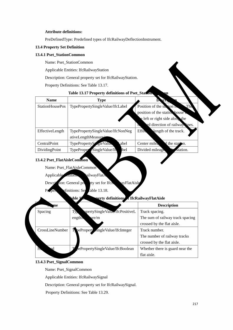
217
Attribute definitions:
PreDefinedType: Predefined types of IfcRailwayDeflectionInstrument.
13.4 Property Set Definition
13.4.1 Pset_StationCommon
Name: Pset_StationCommon
Applicable Entities: IfcRailwayStation
Description: General property set for IfcRailwayStation.
Property Definitions: See Table 13.17.
Table 13.17 Property definitions of Pset_StationCommon
Name Type Description
StationHousePos TypePropertySingleValue/IfcLabel Position of the station house. The
position of the station house is on
the left or right side along the
forward direction of railway lines.
EffectiveLength TypePropertySingleValue/IfcNonNeg
ativeLengthMeasure/m
Effective length of the track.
CentralPoint TypePropertySingleValue/IfcLabel Center mileage of the station.
DividingPoint TypePropertySingleValue/IfcLabel Divided mileage of the station.
13.4.2 Pset_FlatAisleCommon
Name: Pset_FlatAisleCommon
Applicable Entities: IfcRailwayFlatAisle
Description: General property set for IfcRailwayFlatAisle.
Property Definitions: See Table 13.18.
Table 13.18 Property definitions of IfcRailwayFlatAisle
Name Type Description
Spacing TypePropertySingleValue/IfcPositiveL
engthMeasure/m
Track spacing.
The sum of railway track spacing
crossed by the flat aisle.
CrossLineNumber TypePropertySingleValue/IfcInteger Track number.
The number of railway tracks
crossed by the flat aisle.
HasGuard TypePropertySingleValue/IfcBoolean Whether there is guard near the
flat aisle.
13.4.3 Pset_SignalCommon
Name: Pset_SignalCommon
Applicable Entities: IfcRailwaySignal
Description: General property set for IfcRailwaySignal.
Property Definitions: See Table 13.29.
CRBIM
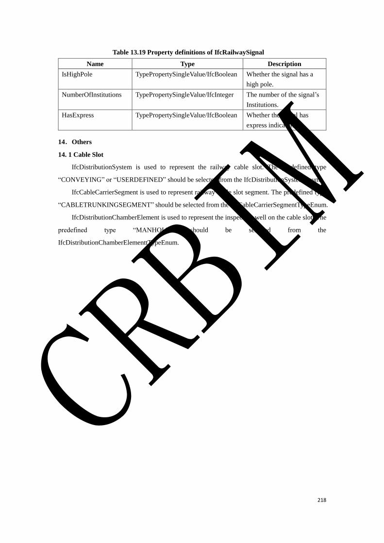
218
Table 13.19 Property definitions of IfcRailwaySignal
Name Type Description
IsHighPole TypePropertySingleValue/IfcBoolean Whether the signal has a
high pole.
NumberOfInstitutions TypePropertySingleValue/IfcInteger The number of the signal’s
Institutions.
HasExpress TypePropertySingleValue/IfcBoolean Whether the signal has
express indicator.
14.Others
14. 1 Cable Slot
IfcDistributionSystem is used to represent the railway cable slot. The predefined type
“CONVEYING” or “USERDEFINED” should be selected from the IfcDistributionSystemEnum.
IfcCableCarrierSegment is used to represent railway cable slot segment. The predefined type
“CABLETRUNKINGSEGMENT” should be selected from the IfcCableCarrierSegmentTypeEnum.
IfcDistributionChamberElement is used to represent the inspection well on the cable slot. The
predefined type “MANHOLE” should be selected from the
IfcDistributionChamberElementtTypeEnum.
CRBIM


