water Article Rainwater Harvesting Typologies for UK Houses: A Multi Criteria Analysis of System Configurations Peter Melville-Shreeve *, Sarah Ward and David Butler Centre for Water Systems, University of Exeter, Exeter EX4 4QF, UK; [email protected] (S.W.); [email protected] (D.B.) * Correspondence: [email protected]; Tel.: +44-1392-723600 Academic Editor: Ataur Rahman Received: 6 October 2015; Accepted: 25 March 2016; Published: 1 April 2016 Abstract: Academic research and technological innovation associated with rainwater harvesting (RWH) systems in the UK has seen a shift of emphasis in recent years. Traditional design approaches use whole life cost assessments that prioritise financial savings associated with the provision of an alternative water supply. However, researchers and practitioners are increasingly recognising broader benefits associated with rainwater reuse, such as stormwater attenuation benefits. This paper identifies and describes a set of novel RWH system configurations that have potential for deployment in UK houses. Conceptual schematics are provided to define these innovations alongside traditional configurations. Discussion of the drivers supporting these configurations illustrates the opportunities for RWH deployment in a wide range of settings. A quantitative multi criteria analysis was used to evaluate and score the configurations under a range of emerging criteria. The work identifies several RWH system configurations that can outperform traditional ones in terms of specified cost and benefits. Selection of a specific RWH technology is shown to be highly dependent on user priorities. It is proposed that the system configurations highlighted could enable RWH to be cost-effectively installed in a broad set of contexts that have experienced minimal exploitation to date. Keywords: configurations; decision support; multi criteria analysis; product innovation; rainwater harvesting; sustainable drainage systems; source control 1. Introduction 1.1. Rainwater Harvesting at UK Houses Rainwater harvesting (RWH) systems in the UK have traditionally been installed at domestic residences for the single objective of providing a non-potable water supply for use in toilets, laundry facilities and for garden irrigation [1,2]. Unlike some fully off-grid configurations implemented elsewhere [3,4], system configurations in the UK are supplemented by mains water supplies for potable water applications such as drinking, bathing and dishwashing. Germany has seen strong uptake of RWH technologies as reported by Partzsch [5] with 80,000 installations per annum and a total industry value of 340 million Euros. With successful growth in that market driven by policies that seek to (financially) support green technologies, one in three houses constructed in 2005 installed a rainwater tank. However, the nascent UK RWH installation market has developed with early-adopters purchasing well-established technologies that directly derive from installations found in countries where RWH is now mainstream, such as Germany [6] and Australia [7]. In fact, a review of three leading RWH system providers in the UK illustrates that they either license products from European manufacturers or have mimicked such configurations [8–10]. Whilst suitable for some sites, the direct transplantation of these off-the-shelf, traditional RWH system configurations into the UK marketplace could prevent optimal RWH solutions from being installed, Water 2016, 8, 129; doi:10.3390/w8040129 www.mdpi.com/journal/water
Transcript
water
Article
Rainwater Harvesting Typologies for UK Houses:A Multi Criteria Analysis of System Configurations
Peter Melville-Shreeve *, Sarah Ward and David Butler
Academic Editor: Ataur RahmanReceived: 6 October 2015; Accepted: 25 March 2016; Published: 1 April 2016
Abstract: Academic research and technological innovation associated with rainwater harvesting(RWH) systems in the UK has seen a shift of emphasis in recent years. Traditional design approachesuse whole life cost assessments that prioritise financial savings associated with the provision ofan alternative water supply. However, researchers and practitioners are increasingly recognisingbroader benefits associated with rainwater reuse, such as stormwater attenuation benefits. This paperidentifies and describes a set of novel RWH system configurations that have potential for deploymentin UK houses. Conceptual schematics are provided to define these innovations alongside traditionalconfigurations. Discussion of the drivers supporting these configurations illustrates the opportunitiesfor RWH deployment in a wide range of settings. A quantitative multi criteria analysis was used toevaluate and score the configurations under a range of emerging criteria. The work identifies severalRWH system configurations that can outperform traditional ones in terms of specified cost andbenefits. Selection of a specific RWH technology is shown to be highly dependent on user priorities.It is proposed that the system configurations highlighted could enable RWH to be cost-effectivelyinstalled in a broad set of contexts that have experienced minimal exploitation to date.
Keywords: configurations; decision support; multi criteria analysis; product innovation; rainwaterharvesting; sustainable drainage systems; source control
1. Introduction
1.1. Rainwater Harvesting at UK Houses
Rainwater harvesting (RWH) systems in the UK have traditionally been installed at domesticresidences for the single objective of providing a non-potable water supply for use in toilets, laundryfacilities and for garden irrigation [1,2]. Unlike some fully off-grid configurations implementedelsewhere [3,4], system configurations in the UK are supplemented by mains water supplies forpotable water applications such as drinking, bathing and dishwashing. Germany has seen stronguptake of RWH technologies as reported by Partzsch [5] with 80,000 installations per annum and atotal industry value of 340 million Euros. With successful growth in that market driven by policies thatseek to (financially) support green technologies, one in three houses constructed in 2005 installed arainwater tank. However, the nascent UK RWH installation market has developed with early-adopterspurchasing well-established technologies that directly derive from installations found in countrieswhere RWH is now mainstream, such as Germany [6] and Australia [7].
In fact, a review of three leading RWH system providers in the UK illustrates that they eitherlicense products from European manufacturers or have mimicked such configurations [8–10]. Whilstsuitable for some sites, the direct transplantation of these off-the-shelf, traditional RWH systemconfigurations into the UK marketplace could prevent optimal RWH solutions from being installed,
Water 2016, 8, 129; doi:10.3390/w8040129 www.mdpi.com/journal/water
as the current market-place only offers a limited range of technologies to potential purchasers.Additionally, these traditional RWH systems are best suited to new build houses with large gardens ordriveways (under which tanks can be placed) with high non-potable water consumption. They canbe difficult and costly to retrofit and may have high maintenance requirements [11]. House buildingtrends in the UK are for smaller properties with low-flush toilets and less garden space. Recent researchon water using practices revealed that 62% of the sample had some garden applications for whichrainwater could be used (plants, flowers, lawn). However, 26% of this subset did not irrigate or watertheir gardens, but simply waited for rain [12]. In combination, this means that there is a growingneed for retrofitable RWH systems, which utilise smaller rainwater tanks. However, there are fewcommercially-available systems to address this opportunity. Furthermore, optimal RWH systemsmight be designed to respond to a wider set of drivers than simply achieving (non-potable) watersupply, such as reducing total water related energy consumption and improving stormwater control.
Minimal government incentives, subsidy or support for RWH means the UK market remainsnascent. At the residential property scale, installation rates remain low with the market reportedlyworth just £8 million in 2009 [13]. This is no doubt due to the whole life cost benefits of traditionaltechnologies resulting in long payback periods to individual purchasers [14]. There is thereforea compelling case to develop an affordable, retrofittable and multi-benefit range of RWH systemconfigurations and options to respond to these property and regime level drivers.
In this paper, traditional and innovative RWH systems have been identified and theirconfigurations described. Secondly, a set of criteria are defined that enable RWH system configurationsto be evaluated using multi criteria analysis (MCA). The outputs from the research illustrate the abilityof RWH systems to achieve a number of objectives and the methods are intended to support designers,householders, water companies and installers in understanding the broader opportunities presentedby emerging innovative RWH technologies.
1.2. Existing Cost–Benefit Approaches to RWH Assessment
A straightforward method of financial appraisal can be achieved by evaluating the payback periodfor a RWH system. This sets the capital cost against the long-term savings generated from the reducedwater supply and associated sewerage costs. Contemporary RWH studies and modelling tools alsointegrate the operational costs and planned maintenance costs (for example pump replacement andtank cleaning) [15]. Such an approach was demonstrated by Roebuck et al. [14], who concluded thata whole life cost (WLC) approach is most appropriate for undertaking financial appraisal of RWHsystems in the UK. This work advocated the need to include capital, maintenance, operational anddecommissioning costs while attributing financial benefits to the savings linked to water and seweragetariff reductions. Ward et al. [11] agree that WLC approaches represent best practice and propose thatdaily rainfall datasets should be deployed to enable more accurate modelling of RWH systems [16].Roebuck and colleagues’ later work [17] also illustrated that use of simplified tools (for example thosethat do not account for WLC) can result in designs that have hypothetically viable payback periodsbut cost more to maintain and operate than they save when whole lifecycle costs are included.
A wider review of literature and RWH system design tools illustrates that appraisal beyondfinancial benefit is lacking [18–20]. An appraisal under a single objective “maximise whole-lifefinancial benefit of water reuse” omits many of the nuanced benefits offered by RWH systems.Consequently, examination of novel RWH system configurations benchmarked against a wider set ofcriteria is warranted.
1.3. A Framework for RWH Evaluation under a Range of Criteria
Following Coombes [21], the work set out in this paper develops a decision space that tradesoff whole life benefits and whole life costs. This concept neatly frames the need for innovation in thecontext of the UK’s RWH industry through visualizing system configurations using a Pareto front.The delivery of optimal water management is currently constrained by the size and variety of the
Water 2016, 8, 129 3 of 18
original set of solutions at the designer’s disposal. For example, if the designer of a new housingdevelopment seeks to install a water reuse system, they might reasonably investigate the relevantBritish Standards; BS8595:2013 Code of practice for the selection of water reuse systems [22] andBS8515:2009+A1:2013 Rainwater Harvesting Systems—Code of practice [2]. The components andconfigurations included within the standards might be extracted and evaluated on a case-by-casebasis using a handful of cost benefit metrics. These designs represent the total set of potential designsolutions. The designer may conclude that RWH is not a cost effective option, as no solutions evaluatedmet the designer’s budgetary constraints. Consequently, the initial target to incorporate water reuseinto the development remains unmet. In graphical form, this is conceptualised in Figure 1. It is evidentfrom this graphic that expanding the original set of solutions can increase the likelihood that suitableRWH system configurations can be identified. In this example, Figure 1 identifies that two previously“unseen” solutions are available to the designer that are within budget but were not considered inthe previously limited decision space. It is proposed that the development of a quantitative RWHassessment tool that incorporates a range of criteria will enable practitioners to widen the decisionspace and implement RWH systems in locations where single objective benefit appraisals fail to satisfycost benefit criteria.
Water 2016, 8, 129 3 of 18
The delivery of optimal water management is currently constrained by the size and variety of the original set of solutions at the designer’s disposal. For example, if the designer of a new housing development seeks to install a water reuse system, they might reasonably investigate the relevant British Standards; BS8595:2013 Code of practice for the selection of water reuse systems [22] and BS8515:2009+A1:2013 Rainwater Harvesting Systems—Code of practice [2]. The components and configurations included within the standards might be extracted and evaluated on a case-by-case basis using a handful of cost benefit metrics. These designs represent the total set of potential design solutions. The designer may conclude that RWH is not a cost effective option, as no solutions evaluated met the designer’s budgetary constraints. Consequently, the initial target to incorporate water reuse into the development remains unmet. In graphical form, this is conceptualised in Figure 1. It is evident from this graphic that expanding the original set of solutions can increase the likelihood that suitable RWH system configurations can be identified. In this example, Figure 1 identifies that two previously “unseen” solutions are available to the designer that are within budget but were not considered in the previously limited decision space. It is proposed that the development of a quantitative RWH assessment tool that incorporates a range of criteria will enable practitioners to widen the decision space and implement RWH systems in locations where single objective benefit appraisals fail to satisfy cost benefit criteria.
Figure 1. Conceptualising the benefits of innovative design of novel RWH system configurations (adapted from Coombes [21]).
1.4. Multi Criteria Analysis
Multi criteria analysis (MCA) methods are frequently used in the field of integrated water management to support decision makers who wish to differentiate between options with complex, multi-faceted characteristics [23–26]. The methods typically follow a structure as follows [27]: define the problem, identify alternative options, define criteria and associated objectives, populate performance matrix and evaluate performance against criteria. With values for each criteria defined, previous studies have deployed a range of methods such as weighted summation or range of value methods [25]. These techniques add a final tier of expert judgement to enable the preferred option to be selected from those which perform strongly. The MCA method used in this paper describes innovative systems and identifies a process for differentiating between them. In a final step, three scenarios are defined to assess technology selection based on user preferences.
Figure 1. Conceptualising the benefits of innovative design of novel RWH system configurations(adapted from Coombes [21]).
1.4. Multi Criteria Analysis
Multi criteria analysis (MCA) methods are frequently used in the field of integrated watermanagement to support decision makers who wish to differentiate between options with complex,multi-faceted characteristics [23–26]. The methods typically follow a structure as follows [27]:define the problem, identify alternative options, define criteria and associated objectives, populateperformance matrix and evaluate performance against criteria. With values for each criteria defined,previous studies have deployed a range of methods such as weighted summation or range of valuemethods [25]. These techniques add a final tier of expert judgement to enable the preferred optionto be selected from those which perform strongly. The MCA method used in this paper describesinnovative systems and identifies a process for differentiating between them. In a final step, threescenarios are defined to assess technology selection based on user preferences.
Water 2016, 8, 129 4 of 18
2. Method
The method adopted in this paper is a simple linear weighted MCA based on the following 6steps, adapted from [27].
Step 1—Define the problem and associated parameters. A well-defined problem statement wasneeded to enable the MCA to be developed.
Step 2—Identify alternative options. A comprehensive literature review of existing andemerging RWH system configurations was conducted to identify and define their characteristics.
Step 3—Define criteria and associated objectives. The literature review identified a numberof drivers (objectives) which have enabled five criteria to be defined for RWH implementation at ahousehold level in the UK. Details of technologies and criteria were established from a broad rangeof sources, which included: patent searches, meetings with industry suppliers, site visits, conferenceattendance, facilitating workshops, innovation events with rainwater practitioners, collaborativedesign partnerships and reviews of industry texts and the peer-reviewed literature.
Step 4—Populate performance matrix. With system configurations and criteria defined,quantitative methods were used to evaluate each configuration.
Step 5—Evaluate performance against criteria. Results were generated to benchmark theconfigurations against one another to demonstrate how they perform when each criteria is consideredas the sole objective in selecting a RWH configuration.
Step 6—Scenario Testing. Three hypothetical scenarios were defined and weightings allocatedto the MCA in order to illustrate the effectiveness of the MCA approach as a decision support tool.
The UK has seen many developments and innovations in RWH design configurations, both withinthe RWH industry and within the academic research community [28–32]. The identification of details ofthese systems form the basis of Step 2. A summary of traditional and innovative RWH configurations isdescribed in Section 3.2. A matrix was constructed to allow values for each configuration to be derivedfrom literature or calculated against the five criteria determined in Section 3.3. The criteria wereutilised to evaluate the configurations against each objective. To achieve this, a fixed set of parameterswas used to define a case study house against which each RWH system could be assessed using atime-series model. For simplicity, the paper illustrates how the systems compare when assessed againsta single house. The intention is that the method can be further utilised in order to allow decisionmakers to assess the range of RWH systems against any site.
3. RWH System Configurations and Drivers
This section describes the process of applying the previously described 6 MCA steps using theRWH industry as its focus.
3.1. Step 1—Define the Problem and Associated Parameters
The method set out in this paper seeks to answer the following problem statement:“Identify a quantitative method to evaluate the broad benefits of a range of traditional and novel
RWH technologies at a given location.”A set of fixed parameters was generated to enable comparison of RWH technologies to be
undertaken at a domestic property. Parameters for a typical UK house are described in Table 1.The property is assumed to have: a pitched roof with a plan area of 60 m2, four occupants utilising150 L/person/day (with a usage ratio based on existing literature [33]), space and structural capacityfor up to 2 No. 0.25 m3 loft or wall mounted header tanks, and can accommodate up to 5 m3 of aboveground or below ground storage.
Water 2016, 8, 129 5 of 18
Table 1. Defining the characteristics for a typical UK house.
‚ 0.5 m3 if located in loft‚ 0.5 m3 if located externally for gravity feed‚ 5 m3 if located at or below ground level.
(Storage volume reduced to 4.5 m3 wheremains top up also enters storage tank)
Time-series rainfall data Exeter, UK Daily rainfall (mm) records for Exeter, UK
3.2. Step 2—Identifying Alternative Options: RWH System Configurations
RWH systems comprise a number of components, which typically include: gutter systems, filters,storage tanks, tank overflows, pumps, pressure vessels, pipework, valves, backup supply systems,sensors/float switches and electronic controllers. Details of these components can be identified throughgrey-literature available from RWH providers [8–10] and are described in BS8515:2009+A1:2013 [2].Detailed descriptions of well-defined components are not included here as they are already suitablydescribed in existing texts [34]. Existing literature describing RWH typologies chiefly focuses on asmall number of potential configurations [6]. Furthermore, some terminology used does not matchterms used by current UK RWH suppliers. The following typologies aim to extend and clarifythese terminologies.
3.2.1. Best Practice in the UK: Traditional RWH System Configurations
In the UK, residential RWH systems typically utilise buried tanks although above ground tanksare also sometimes installed. Pumped flows are delivered via direct-feed or header tank systems.Consequently, four traditional RWH system configurations were identified as representing currentbest practice for household installations as described in Figure 2 [8–10]. The systems illustrated inFigure 2 each capture rainfall from the roof and store the filtered water in below ground (Figure 2a,c) orabove ground (Figure 2b,d) tanks. Rainwater is then delivered by a submersible pump to non-potableapplications either by direct-feed (Figure 2a,b) or via a header tank (Figure 2c,d). For the purposes ofclarity, the overflow outlet from the system is described as a sewer (for example a combined sewernetwork) although RWH systems can also discharge to an infiltration device, surface water sewer orwatercourse, depending on the site setting.
Water 2016, 8, 129 6 of 18Water 2016, 8, 129 6 of 18
Figure 2. Conceptual schematics for four traditional rainwater harvesting RWH configurations used in the UK. (a) below ground, direct-feed ;(b) above ground, direct-feed ;(c)below ground, header tank feed ;(d) above ground, header tank feed.
3.2.2. Emerging Practice in UK: Innovative RWH System Configurations
In addition to the traditional RWH system configurations set out in Figure 2, a series of RWH innovations were identified. Through the collection of evidence, as described in Table 2, it is apparent that stormwater control potentially represents an additional key driver for innovation of RWH technologies. A summary of the innovations identified is set out in Table 2 and the configurations are diagrammatically illustrated in Figure 3.
A common theme with the first five of these innovative RWH system configurations is a high-level roof-runoff inlet, which facilitates the replacement of the large ground-level tank with wall-mounted or internal header tanks. This enables rainwater to be propelled by low energy pumps or flow under gravity into header tanks, which in turn feed appliances by gravity. A second common theme with the next three innovative RWH system configurations (Figure 3f-h) is the inclusion of a “sacrificial” amount of storage that is utilised for stormwater control. These dual-purpose RWH systems enable flow to be released from storage either passively, using an orifice at a specifically designed height in the tank, or actively through a release valve. Figure 3h describes a system that includes functionality to enable a central authority (for example the water service provider (WSP) to control tank levels based on predictive rainfall, to enable real time control of rainwater discharges to a sewer network. The final innovative RWH system is a treatment train consisting of filtration, UV and ozonation, which is designed to enable harvested rainwater to be treated to potable standards.
Figure 2. Conceptual schematics for four traditional rainwater harvesting RWH configurations used inthe UK. (a) below ground, direct-feed ;(b) above ground, direct-feed ;(c)below ground, header tankfeed ;(d) above ground, header tank feed.
3.2.2. Emerging Practice in UK: Innovative RWH System Configurations
In addition to the traditional RWH system configurations set out in Figure 2, a series of RWHinnovations were identified. Through the collection of evidence, as described in Table 2, it is apparentthat stormwater control potentially represents an additional key driver for innovation of RWHtechnologies. A summary of the innovations identified is set out in Table 2 and the configurations arediagrammatically illustrated in Figure 3.
Water 2016, 8, 129 7 of 18
Table 2. Innovative RWH system configurations.
System Provider and Patent No. Description Country References
A patented suction pump system that captures rainwater fromdownpipes and stores rainwater in large header tanks.Easily retrofitted, with no external tanks.
UK [35,36]
Aqua Harvest and SavePatent: GB2480834
A patented gutter-located pump system lifts rainwater intolarge header tanks. Easily retrofitted, with no external tanks. UK [36,37]
Atlas Water HarvestingPatent: GB2496729 and Rooftop RainPatent:GB2475924 and GB2228521
A gravity-fed inlet is installed within the roof to enable ~50% of theroof to flow under gravity into large header tanks within the loft. UK [38–41]
Aqualogic (ARC);Rainbeetle GB2501313-B
An externally mounted tank, located near the roofline isinstalled to store rainwater and deliver flows by gravity. UK [42]
Hydromentum, Water PoweredTechnologies Ltd., Bude, UK.
An externally mounted header tank, drives a passively powered(zero electricity) pump to lift flows to a header tank. UK [43]
A passive rainwater discharge control (flow attenuation system)for inclusion within RWH tanks to ensure some storage is alwaysmaintained to attenuate extreme storm events.
Germany, USA, UK [44–46]
KloudKeeper Ltd., Exeter, UK.An active rainwater discharge control (flow attenuation system)for inclusion within RWH tanks to ensure some storage is alwaysmaintained to attenuate extreme storm events.
UK [2]
IOTA,Melbourne South East Water (Aus)and Geosyntec, Boca Raton, FL, (USA)
A real-time control system that enables weather forecast data tosupport a decision maker to empty a RWH tank in a controlledway before a storm, thus ensuring capacity is available tocapture extreme storm events.
Australia, Korea, USA [47,48]
RainSafe, Newtown Mt Kennedy, Ireland Rainwater treatment system that enables harvestedrainwater to meet potable water standards. UK [49]
Water 2016, 8, 129 8 of 18
Water 2016, 8, 129 8 of 18
Figure 3. Cont.
Figure 3. Cont.
Water 2016, 8, 129 9 of 18
Water 2016, 8, 129 9 of 18
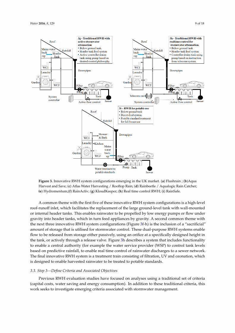
Figure 3. Innovative RWH system configurations emerging in the UK market. (a) Flushrain ; (b)Aqua Harvest and Save; (c) Atlas Water Harvesting / Rooftop Rain; (d) Rainbeetle / Aqualogic Rain Catcher; (e) Hydromentum;(f) RainActiv; (g) KloudKeeper; (h) Real time control RWH; (i) RainSafe.
3.3. Step 3—Define Criteria and Associated Objectives
Previous RWH evaluation studies have focused on analyses using a traditional set of criteria (capital costs, water saving and energy consumption). In addition to these traditional criteria, this work seeks to investigate emerging criteria associated with stormwater management.
3.3.1. Traditional Criteria: Capital Costs, Water Savings and Energy Consumption
RWH systems are currently installed in the UK to provide alternative water supplies to displace reliance on potable water. Cash savings are generated for homeowners as metered water charges are reduced accordingly [1]. Minimising the capital cost of a system represents the first driver for consideration when appraising RWH configurations. Re-configuring RWH systems to minimise the capital cost could enable the market to further develop by increasing affordability to a larger number of consumer segments. A RWH system’s ability to reduce water demand (i.e., contribute to water efficiency) represents the second key criteria when assessing configurations. Reducing the cost of the configuration (perhaps by reducing the tank size and thus storage volume) may reduce the water savings associated with the installation, so assessment of this criterion enables the traditional assessment of RWH benefits to be evaluated. Detailed price comparison information was made available by a UK provider [50]. Where cost data have not been available (for example where prototype systems were identified that have yet to reach the marketplace), estimates were compiled based on component costs and anticipated labour requirements.
Energy consumption associated with the operation of RWH systems has been comprehensively investigated [51]. Roebuck et al. [14,17], illustrates the need to monitor and plan for operational
Figure 3. Innovative RWH system configurations emerging in the UK market. (a) Flushrain ; (b)AquaHarvest and Save; (c) Atlas Water Harvesting / Rooftop Rain; (d) Rainbeetle / Aqualogic Rain Catcher;(e) Hydromentum;(f) RainActiv; (g) KloudKeeper; (h) Real time control RWH; (i) RainSafe.
A common theme with the first five of these innovative RWH system configurations is a high-levelroof-runoff inlet, which facilitates the replacement of the large ground-level tank with wall-mountedor internal header tanks. This enables rainwater to be propelled by low energy pumps or flow undergravity into header tanks, which in turn feed appliances by gravity. A second common theme withthe next three innovative RWH system configurations (Figure 3f-h) is the inclusion of a “sacrificial”amount of storage that is utilised for stormwater control. These dual-purpose RWH systems enableflow to be released from storage either passively, using an orifice at a specifically designed height inthe tank, or actively through a release valve. Figure 3h describes a system that includes functionalityto enable a central authority (for example the water service provider (WSP) to control tank levelsbased on predictive rainfall, to enable real time control of rainwater discharges to a sewer network.The final innovative RWH system is a treatment train consisting of filtration, UV and ozonation, whichis designed to enable harvested rainwater to be treated to potable standards.
3.3. Step 3—Define Criteria and Associated Objectives
Previous RWH evaluation studies have focused on analyses using a traditional set of criteria(capital costs, water saving and energy consumption). In addition to these traditional criteria, thiswork seeks to investigate emerging criteria associated with stormwater management.
Water 2016, 8, 129 10 of 18
3.3.1. Traditional Criteria: Capital Costs, Water Savings and Energy Consumption
RWH systems are currently installed in the UK to provide alternative water supplies to displacereliance on potable water. Cash savings are generated for homeowners as metered water chargesare reduced accordingly [1]. Minimising the capital cost of a system represents the first driver forconsideration when appraising RWH configurations. Re-configuring RWH systems to minimisethe capital cost could enable the market to further develop by increasing affordability to a largernumber of consumer segments. A RWH system’s ability to reduce water demand (i.e., contribute towater efficiency) represents the second key criteria when assessing configurations. Reducing the costof the configuration (perhaps by reducing the tank size and thus storage volume) may reduce thewater savings associated with the installation, so assessment of this criterion enables the traditionalassessment of RWH benefits to be evaluated. Detailed price comparison information was madeavailable by a UK provider [50]. Where cost data have not been available (for example where prototypesystems were identified that have yet to reach the marketplace), estimates were compiled based oncomponent costs and anticipated labour requirements.
Energy consumption associated with the operation of RWH systems has been comprehensivelyinvestigated [51]. Roebuck et al. [14,17], illustrates the need to monitor and plan for operational energyconsumption associated with pumping rainwater in RWH systems. Vieira et al. [51], published anextended review of power consumption for RWH systems and drew comparisons against a rangeof alternative water resources. This research confirmed that theoretical data for median energyconsumption (0.20 kWh/m3) typically underestimate the data from empirical studies (1.40 kWh/m3).Viera et al. [51] also exemplified the challenges associated with generalisations in energy consumption.Factors such as pump efficiency, pipe friction, fittings (e.g., controls such as ball valves), usage rates,pump start-up factors and control systems all have a role to play. In the UK, Ward et al. [52], showedthat electricity use for a traditional RWH system installed at an office building was 0.54 kWh/m3.Raw data were also provided by a supplier who monitored their traditional household-scale RWHsystem (RainDirector) with a header tank feed. This illustrated that it achieved an energy consumptionof 0.68 kWh/m3 in a laboratory setting and that fewer pump starts were needed than for equivalentdirect feed systems [53], which would therefore be expected to have a higher consumption.
The mean energy consumption for UK municipal water supply has been reported as0.60 kWh/m3 [54]. European average municipal water supplies are also quoted at a similar level of0.46 kWh/m3 [54]. RWH configurations that are able to provide water at a lower energy consumptionthan the municipal supply could therefore be supported on energy/carbon emission reduction grounds.Consequently, the energy consumption of each RWH configuration represents a suitable criterion toreview in terms of kWh/m3 of water delivered [51]. Where possible, energy costs allocated to eachRWH system were taken from literature, although some first principles assumptions were necessary(for example RWH systems with lower total head are likely to have a lower energy consumption thanthose which pump against a higher head).
3.3.2. Emerging Criteria: Stormwater Management and Reducing Combined Sewer Overflows
Through intercepting and using rainwater where it falls (source control), stormwater discharges tosewer systems are reduced as less rainwater enters the sewer network during a storm. Gerolin et al. [30],illustrated that RWH can reduce stormwater discharges successfully when the non-potable demandof a property exceeds the rainwater yield. Supporting this, a number of modelling studies on RWHsystems have demonstrated their ability to reduce stormwater runoff volumes and rates [55–58].However, none of the traditional systems outlined in Figure 2 is designed to focus on this functionality.
Variability in extreme rainfall events has been evaluated by Lash et al. [59]. This study incorporatedmodelling approaches (via a probabilistic tank-sizing tool) applied to case study locations in the UKusing UK Climate Projections 2009 data. Analysis revealed tank sizes would need to be larger inorder to accommodate the increased likelihood of periods with no rainfall. This approach wouldadd support to historic stormwater control approaches set out in Gerolin et al. [30], which calls for
Water 2016, 8, 129 11 of 18
intentionally oversized RWH tanks to minimise stormwater discharges. The original British Standardfor RWH, BS8515:2009 [60], included an approach that encouraged users to size storage tanks tosupply a household’s non-potable water demand for 18 days. The Standard’s “design methods” didnot include parameters relating to stormwater control. This single objective approach potentiallydiscouraged technological innovation from RWH system suppliers. Despite this, some technologicalinnovation has been achieved as systems have become increasingly easy to install due to the “plug andplay” nature of the components provided [9]. The original Standard also suggests that designers canimplement systems that achieve stormwater control by including: “green roofs; a tank which attenuatesflows with an outlet throttle to discharge excess flows; a large tank which is sized for stormwater storageand automatically pumped out or otherwise drained; a tank which is connected to an infiltration system forexcess flows.” [60] (p. 32). A recent update to the British Standard [2] now includes an additionaltechnical annex that encourages the design of source control benefits when sizing RWH. However, thestormwater control objective remains outside the scope of the Standard’s core tank-sizing calculations.The UK’s incumbent RWH system providers do not currently produce systems that provide sourcecontrol in line with UK guidance. However, it is anticipated that novel configurations that achievethis will be available in the near future as development is underway and products are beginning to belaunched [44].
Controlling stormwater discharges to combined sewer networks can mitigate the risks ofpollution events from sewage spills during intense rainfall. Reducing combined sewer overflowdischarges (in terms of frequency and volume) represents a key area of Asset Management Plan (AMP)investment for a number of UK WSPs [61]. WSP projects such as RainScape, WaterShed and theUrban Demonstrator are underway, which seek to deliver and monitor pilot studies where retrofitstormwater management solutions are being trialled to reduce sewer flooding and associated pollutionof watercourses from spills at combined sewer overflows [61–63]. RWH systems that are configured tosatisfy the stormwater reductions targeted by WSPs could potentially see them become a viable optionalongside other retrofit SuDS approaches over the next decade.
RWH systems evaluated in this study were appraised against two stormwater-related criteria:(1) The reduction in peak daily stormwater discharge volumes; and (2) The reduction in annual averagestormwater discharge volumes.
3.3.3. Summarising Criteria for Evaluating RWH Design Configurations
The discussion presented in the previous sections enabled a range of criteria (and associatedobjectives) to be defined. These are summarised in Table 3 and can be used to evaluate the RWHconfigurations outlined in Figures 2 and 3. Other criteria, such as the ease of retrofitability, end-useracceptability and lifetime maintenance requirements, have not been considered in the present analysis,but are the subject of on-going research.
Table 3. Criteria for evaluation of RWH system configurations.
Criteria Objective
C1 Capital cost of RWH system (£/installation) O1 Minimise capital cost of system
C2 Water Efficiency (m3/annum potable saved) O2 Maximise water saving of system
C3 Change in operational energy consumptionfor water supply (kWh/annum)
O3 Minimise energy required tosupply household water
C4 Reduction in stormwater flowduring extreme events (m3/day)
O4 Minimise discharge volume of rainwater duringlargest 24 h storm in 20 year time-series
C5 Reduction in annual stormwaterdischarge to sewer (m3/annum)
O5 Minimise annual averagedischarge volume to sewer network
Water 2016, 8, 129 12 of 18
3.4. Step 4—Populating Assessment Matrix: Details of Quantitative Assessment Methods and Criteriafor Calculation
In order to populate the assessment matrix, an input/output flow balance model was developedas a VBA spreadsheet tool, based on earlier RWH studies [2,34,64], but here incorporating additionalstormwater related outputs. The model uses the “Yield After Spillage” algorithm whereby rainwater isadded to the storage volume recorded for the previous time step. Next excess flows are overflowedprior to extracting demand at that time step [64]. Where intentional stormwater discharges are releasedfrom either passive or active controls, these also occur prior to demand being extracted [34]. A runofffactor of 0.9 is assumed. A daily time step was used, which matched the 20-year input rainfall timeseries for Exeter, UK. The model parameters used to define the property and system simulated aregiven in Table 1. Criteria C2 (water saving), C4 (reduction in maximum daily stormwater discharged)and C5 (reduction in average annual stormwater discharged) were calculated from the flow balancefor each RWH system. C1 (capital cost) and C3 (change in operational energy consumption) werecalculated as explained in the next section. The model enables outputs to be derived from an annualsimulation with rainfall, demand and stormwater spill volumes calculated at the daily time step.Outputs were generated for each day of the year, and the simulation was repeated using 20 annualrainfall files.
C1 Capital cost of RWH system: Values for this criterion were derived outside the flow balancemodel. They were based on best available information on material costs and labour costs required toinstall each RWH system evaluated. Costs are defined in terms of £/installation and as a percentage ofthe highest cost option.
C2 Water efficiency: Water efficiency was taken as the average non-potable water demandsatisfied by the RWH system over the 20-year simulation period and is given in m3/annum.The house’s remaining potable water demand and the reduction in potable water usage were calculated.
C3 Change in operational energy consumption for water supply: Operational powerconsumption for each configuration was taken from the literature with first principles used todifferentiate between novel systems where empirical data were not available. Power consumptionincreases and decreases for annual water supply were recorded as a percentage of the baseline scenario(i.e., a house without RWH receiving only municipal water).
C4 Reduction in stormwater flow during extreme events: The largest 24 h storm event recordedover the 20-year period was used to evaluate each RWH system’s ability to reduce the discharge volume.The difference between the volume controlled when each RWH system was modelled compared withthe volume spilled without RWH was used to define these values. The percentage change between thescenarios was also calculated (i.e., the percentage of stormwater successfully controlled by each RWHsystem during the largest storm event).
C5 Reduction in annual stormwater discharge to sewer: The annual average reduction instormwater discharges to the sewer was derived as the difference between uncontrolled overflows tothe sewer when RWH is included vs. the annual volume spilled without RWH installed. The percentagechange between the scenarios was also calculated (i.e., the percentage of annual stormwater successfullycontrolled by each RWH system).
With simulations completed and outputs derived for the range of options tested, the performancematrix was populated and an analysis conducted as described in Section 4.1.
4. Results and Discussion
4.1. Step 5—Evaluate Performance of RWH Configurations against Criteria
Using the quantitative assessment methods described, an evaluation matrix was defined (Table 4)to summarise simulated performance of the RWH configurations under each criteria.
Water 2016, 8, 129 13 of 18
Table 4. Populated Evaluation Matrix for Criteria Associated With 13 RWH Configurations.
CriteriaRWH System (Reference Figure)
No RWH 2a 2b 2c 2d 3a 3b 3c 3d 3e 3f 3g 3h 3i
C1 Capital cost of RWH system (£) 0 4300 3800 4800 4300 1050 1030 1000 1000 2000 5300 5550 6300 6100C1 Capex relative to highest cost option (%) 0 68 60 76 68 17 16 16 16 32 84 88 100 97C2 Water Saved (m3/annum) 0 34 34 34 34 23 23 16 23 7 32 34 34 40C2 Mains water consumed (m3/annum) 219 185 185 185 185 196 196 202 196 212 187 185 185 179C2 Water Efficiency: Change in mains water use/annum (%) 100 84 84 84 84 89 89 92 89 97 85 84 84 82C3 Energy cost for RWH system (kWh/m3) 0.0 1.1 1.0 0.8 0.7 0.1 0.1 0.0 0.0 0.0 0.7 0.8 0.9 2.0C3 Energy cost of rainwater delivered per annum (kWh) 0 38 35 28 24 3 3 0 0 0 22 28 31 80C3 Energy cost of mains water used per annum (kWh) 131 111 111 111 111 117 117 121 117 127 112 111 111 107C3 Total energy cost per annum (kWh) 131 148 145 138 134 120 120 121 117 127 135 138 142 187C3 Change in operational energy (kWh/annum) 0 17 14 7 3 ´11 ´11 ´9 ´13 ´4 3 7 10 56C3 Change in operational energy (%) 100 113 110 105 103 92 92 92 89 97 102 105 108 143C4 Reduction in stormwater flow during extreme event (m3) 0 3.3 3.3 3.3 3.3 0.5 0.5 0.5 0.5 0.5 2.5 3.3 4.9 4.5C4 Change in stormwater flow during extreme event (%) 0 67 67 67 67 10 10 10 10 10 51 67 100 92C5 Reduction in annual stormwater discharge to sewer (m3/annum) 0 37 37 37 37 22 22 17 22 8 33 37 40 40C5 Change in annual stormwater discharge to sewer (%) 0 91 91 93 93 56 56 43 56 20 82 93 100 100
Water 2016, 8, 129 14 of 18
Figure 4 illustrates the ability of each system to perform when plotted against the five criteria.This figure describes the data in a normalised format. For C1–C5, each value is divided by themaximum score to give output values between 0 and 1. For C4 and C5, this value is subtracted from 1.Hence, the system with a value closest to 0 is the best performing under that criterion. When a singlecriterion is selected, the results show that there is always at least one novel configuration availablethat outperforms the four traditional systems (Systems 2a-d). This illustrates that the current RWHconfigurations deployed in the UK do not necessarily represent the optimal design when broadercriteria are included in their evaluation. The traditional RWH systems are outscored by a numberof novel RWH system configurations in relation to a number of criteria (for example System 3b andSystem 3d have lowest cost (C1) and lowest energy (C3) ranks). The real time control strategy associatedwith System 3h was able to fully prevent uncontrolled stormwater spills for every storm in the 20-yearstudy period. In addition, the high demand (600 L/day) associated with System 3.i’s potable useensured this system was also able to reduce the largest storm event in 20 years by 92%. The passivestormwater controls associated with System 3g reduced the extreme storm event by 67% and limitedtotal stormwater discharge volumes to just 7% of the “No RWH” scenario. Evidence from this analysissuggests that the current RWH systems being implemented in the UK can be improved to better satisfythe criteria highlighted in this paper.Water 2016, 8, 129 14 of 18
Figure 4. Normalised performance of RWH configurations against a range of design criteria (best scoring systems have lowest values for each criteria).
4.2. Step 6—Scenario Testing
The MCA developed in this paper can be deployed as a method for selecting a configuration for a specific site by adding user-based weightings to define the relative importance of each criterion. Such an approach could be deployed by decision makers to test how different weightings affect the selection of a RWH system. To enable this, the decision maker allocates weightings across each criterion that total 1 unit. Three scenarios are defined below to illustrate in outline how the preferred configuration might be defined by differing decision makers. The assumptions made in the scenarios are based on the authors’ knowledge.
Scenario A—A RWH designer concludes that all criteria have equal weight and 0.2 units are applied to each. The MCA suggests that system 3h (traditional RWH with RTC) is the preferred option as it has the lowest total score across all criteria.
Scenario B—A householder wishes to retrofit a RWH system at the lowest possible capital cost. No other criteria hold importance in the system selection process. A weighting of 1 unit is applied to the C1 Capex relative to highest cost option and all other weights set to zero. The MCA selects system 3c3 (roof located, gravity fed gravity RWH) or 3d4 (externally located, gravity fed gravity RWH).
Scenario C—A WSP plans to retrofit houses with RWH as a water demand reduction measure. They also have a secondary objective to reduce peak stormwater flows at a local pumping station. Costs are not an important factor as no alternative solutions have been identified by the WSP. A weighting of 0.75 units is applied to C2 Water Efficiency and 0.25 units allocated to C4 Change in stormwater flow during extreme event to ensure these dominate the remaining criteria. System 3i (RWH for potable use) is identified as dominating other options as this configuration scores best in terms of water demand reduction and is also able to mitigate 92% of the peak storm discharge during the largest storm event tested.
The three scenarios considered above each illustrate the ability of the MCA method to readily offer a high level focus for a designer to identify suitable RWH options under a range of settings/site objectives.
5. Conclusions
This paper presented the identification, description and multi-criteria analysis of existing and novel RWH configurations that could be adopted at UK households to satisfy a broad range of property and regime level drivers. The evaluation criteria were defined as follows: reduce capital
Figure 4. Normalised performance of RWH configurations against a range of design criteria (bestscoring systems have lowest values for each criteria).
4.2. Step 6—Scenario Testing
The MCA developed in this paper can be deployed as a method for selecting a configuration for aspecific site by adding user-based weightings to define the relative importance of each criterion. Suchan approach could be deployed by decision makers to test how different weightings affect the selectionof a RWH system. To enable this, the decision maker allocates weightings across each criterion thattotal 1 unit. Three scenarios are defined below to illustrate in outline how the preferred configurationmight be defined by differing decision makers. The assumptions made in the scenarios are based onthe authors’ knowledge.
Scenario A—A RWH designer concludes that all criteria have equal weight and 0.2 units areapplied to each. The MCA suggests that system 3h (traditional RWH with RTC) is the preferred optionas it has the lowest total score across all criteria.
Water 2016, 8, 129 15 of 18
Scenario B—A householder wishes to retrofit a RWH system at the lowest possible capital cost.No other criteria hold importance in the system selection process. A weighting of 1 unit is applied tothe C1 Capex relative to highest cost option and all other weights set to zero. The MCA selects system 3c3(roof located, gravity fed gravity RWH) or 3d4 (externally located, gravity fed gravity RWH).
Scenario C—A WSP plans to retrofit houses with RWH as a water demand reduction measure.They also have a secondary objective to reduce peak stormwater flows at a local pumping station. Costsare not an important factor as no alternative solutions have been identified by the WSP. A weightingof 0.75 units is applied to C2 Water Efficiency and 0.25 units allocated to C4 Change in stormwater flowduring extreme event to ensure these dominate the remaining criteria. System 3i (RWH for potableuse) is identified as dominating other options as this configuration scores best in terms of waterdemand reduction and is also able to mitigate 92% of the peak storm discharge during the largeststorm event tested.
The three scenarios considered above each illustrate the ability of the MCA method to readilyoffer a high level focus for a designer to identify suitable RWH options under a range of settings/site objectives.
5. Conclusions
This paper presented the identification, description and multi-criteria analysis of existing andnovel RWH configurations that could be adopted at UK households to satisfy a broad range ofproperty and regime level drivers. The evaluation criteria were defined as follows: reduce capitalcosts, maximise water saving efficiency, minimise operational energy consumption associated withwater supply, minimise peak stormwater discharges, and minimise annual stormwater discharges.A broad range of RWH configurations are emerging in the UK marketplace. Through benchmarkingeach configuration using the MCA, it was possible to score each system’s ability to satisfy a numberof key RWH criteria. Evidence from the MCA illustrates that the traditional RWH configurations arenot necessarily the optimum solutions when broader criteria are considered. However, the specifictechnology selected will depend on the preferences of the decision maker or user, as illustrated bythe three scenarios. Based on these results, it is suggested that minor alterations to existing RWHtechnologies, such as integration with real time stormwater control devices, could see demand forRWH systems grow in the years ahead. This may be the case where stormwater control is desirable tomeet drainage design criteria at new developments, or to reduce sewer flooding and spills in existingcombined sewer catchments. The identification of RWH systems as a multi-functional technology isexemplified in this paper. Further empirical studies are now underway to enable novel benefits ofemerging RWH system configurations to be further quantified, understood and exploited by a rangeof decision makers.
Acknowledgments: The study was funded by the UK Engineering & Physical Sciences Research Councilsupported by Severn Trent Water through delivery of a STREAM Engineering Doctorate. Grant reference:EP/G037094/1. The authors also wish to thank the reviewers for their support in developing this paper.
Author Contributions: All authors conceived the methods set out in this paper and pooled grey and academicliterature to enable the review of potential RWH configurations and criteria to be developed. The lead authorwas responsible for synthesising the configurations and applying the methodology. The co-authors providedsignificant technical input to ensure the results and discussion were adequately exploited and described herein.
Conflicts of Interest: The work reported here builds upon a series of research and development projects that havebeen undertaken in collaboration with Severn Trent Water and a number of the RWH system providers referencedin this paper. The authors have sought to balance input from a range of these sources and to minimise the relianceon grey literature when opportunities have permitted.
References
1. Environment Agency. Harvesting Rainwater for Domestic Uses: An Information Guide, 2008. Availableonline: http://www.highland.gov.uk/NR/rdonlyres/F512E7E7-6C8D-4036-ACFF-1DA761006DF8/0/RainwaterHarvestingforDomesticUse.pdf (accessed on 10 July 2015).
Water 2016, 8, 129 16 of 18
2. British Standards Institution. BS 8515:2009+A1:2013—Rainwater Harvesting Systems—Code of Practice;BSI: London, UK, 2013.
3. Ahmed, W.; Vieritz, A.; Goonetilleke, A.; Gardner, T. Health Risk from the Use of Roof-Harvested Rainwaterin Southeast Queensland, Australia, as Potable or Nonpotable Water, Determined Using QuantitativeMicrobial Risk Assessment. Appl. Environ. Microbiol. 2010, 76, 7382–7391. [CrossRef] [PubMed]
4. Texas Water Development Board. The Texas Manual on Rainwater Harvesting, 2005. Available online:http://www.twdb.state.tx.us/innovativewater/rainwater/doc/RainwaterCommitteeFinalReport.pdf(accessed on 15 October 2014).
5. Partzsch, L. Smart regulation for water innovation—The case of decentralized rainwater technology.J. Clean. Prod. 2009, 17, 985–991. [CrossRef]
6. Herrmann, T.; Schmida, U. Rainwater utilisation in Germany: Efficiency, dimensioning, hydraulic andenvironmental aspects. Urban Water 1999, 1, 307–316. [CrossRef]
7. Burns, M.J.; Fletcher, T.D.; Duncan, H.P.; Hatt, B.E.; Ladson, A.R.; Walsh, C.J. The performance of rainwatertanks for stormwater retention and water supply at the household scale: An empirical study. Hydrol. Process.2015, 29, 152–160. [CrossRef]
8. Stormsaver. Rainwater Harvesting Systems. Available online: http://www.stormsaver.co.uk (accessed on22 October 2014).
9. Rainwater Harvesting Ltd. Rainwater Harvesting Systems. Available online: http://www.rainwaterharvesting.co.uk (accessed on 12 August 2015).
10. GRAF. Rainwater Harvesting Systems. Available online: http://www.graf-water.com/rainwater-harvesting.html (accessed on 22 May 2015).
11. Ward, S.; Barr, S.; Butler, D.; Memon, F.A. Rainwater harvesting in the UK—Socio-technical theory andpractice. Technol. Forecast. Soc. Chang. 2012, 79, 1354–1361. [CrossRef]
12. Pullinger, M.; Browne, A.L.; Medd, W.; Anderson, B. Patterns of Practice: Laundry, Bathroom andGardening Practices of Households in England Influencing Water Consumption and Demand Management;Lancaster Environment Centre, Lancaster University: Lancaster, UK, 2013; Available online: http://www.sprg.ac.uk/uploads/patterns-of-water-final-report.pdf (accessed on 4 July 2013).
13. MTW Research. Rainwater Harvesting Market Research & Analysis UK 2010; MTW Research: Cheltenham,UK, 2010.
14. Roebuck, R.M.; Oltean-Dumbrava, C.; Tait, S. Whole life cost performance of domestic rainwater harvestingsystems in the United Kingdom. Water Environ. J. 2011, 25, 355–365. [CrossRef]
15. Neto, R.F.M.; Carvalho, I.D.; Calijuri, M.L.; Santiago, A.D. Rainwater use in airports: A case study in Brazil.Resour. Conserv. Recycl. 2012, 68, 36–43. [CrossRef]
16. Ward, S.L.; Memon, F.A.; Butler, D. Rainwater harvesting: Model-based design evaluation. Water Sci. Technol.2010, 61, 85–96. [CrossRef] [PubMed]
17. Roebuck, R.M.; Oltean-Dumbrava, C.; Tait, S. Can simplified design methods for domestic rainwaterharvesting systems produce realistic water-saving and financial predictions? Water Environ. J. 2012, 26,352–360. [CrossRef]
18. Steffen, J.; Jenson, M.; Pomeroy, C.A.; Burian, S.J. Water Supply and Stormwater Management Benefits ofResidential Rainwater Harvesting in U.S. Cities. J. Am. Water Resour. Assoc. 2013, 49, 810–824. [CrossRef]
19. Jones, M.P.; Hunt, W.F. Performance of rainwater harvesting systems in the southeastern United States.Resour. Conserv. Recycl. 2010, 54, 623–629. [CrossRef]
20. Friedrich, E.; Pillay, S.; Buckley, C.A. The use of LCA in the water industry and the case for an environmentalperformance indicator. Water SA 2007, 33, 443–452. [CrossRef]
21. Coombes, P.J. Rainwater Tanks Revisited: New Opportunities for Urban Water Cycle Management. Ph.D.Thesis, University of Newcastle, N.S.W., Australia, 2002. Available online: http://urbanwatercyclesolutions.com/rainwater-tanks-revisited-new-opportunities-for-integrated-water-cycle-management/ (accessed on 1August 2015).
22. British Standards Institute. BS8595:2013 Code of Practice for the Selection of Water Reuse Systems; BSI: London,UK, 2013.
23. Cinelli, M.; Coles, S.R.; Kirwan, K. Analysis of the potentials of multi criteria decision analysis methods toconduct sustainability assessment. Ecol. Indic. 2014, 46, 138–148. [CrossRef]
24. Urrutiaguer, M.; Lloyd, S.; Lamshed, S. Determining water sensitive urban design project benefits using amulti-criteria assessment tool. Water Sci. Technol. 2010, 61, 2333–2341. [CrossRef] [PubMed]
25. Hajkowicz, S.; Higgins, A. A comparison of multiple criteria analysis techniques for water resourcemanagement. Eur. J. Oper. Res. 2008, 184, 255–265. [CrossRef]
26. Janssen, R. On the use of multi-criteria analysis in environmental impact assessment in The Netherlands.J. Multi-Criteria Decis. Anal. 2001, 10, 101–109. [CrossRef]
27. Department for Communities and Central Government (DCLG). Multi-Criteria Analysis: A Manual;Communities and Local Government Publications: Wetherby, UK, 2009.
28. Diaper, C.; Jefferson, B.; Parsons, S.A.; Judd, S.J. Water-recycling technologies in the UK. J. Charter. Inst. WaterEnviron. Manag. 2001, 15, 282–286. [CrossRef]
29. Lazarova, V.; Hills, S.; Birks, R. Using recycled water for non-potable, urban uses: A review with particularreference to toilet flushing. Water Recycl. Mediterr. Reg. 2003, 3, 69–77.
30. Gerolin, A.; Kellagher, R.B.; Faram, M.G. Rainwater harvesting systems for stormwater management:Feasibility and sizing considerations for the UK. In Proceedings of the Novatech 2010, Lyon, France,27 June–1 July 2010.
31. Parsons, D.; Goodhew, S.; Fewkes, A.; De Wilde, P. The perceived barriers to the inclusion of rainwaterharvesting systems by UK house building companies. Urban Water J. 2010, 7, 257–265. [CrossRef]
32. UK Rainwater Harvesting Association (UKRHA). UKRHA-Installers, 2014. Available online: http://www.ukrha.org/tag/system-installers-servicing/ (accessed on 10 October 2014).
33. Butler, D.; Memon, F.A. Water consumption trends and demand forecasting techniques. In Water DemandManagement; IWA Publishing: London, UK, 2006; pp. 1–26.
34. Roebuck, R.M. A Whole Life Costing Approach for Rainwater Harvesting Systems. An Investigation intothe Whole Life Cost Implications of Using Rainwater Harvesting Systems for Non-Potable Applications inNew-Build Developments in the UK. Ph.D. Thesis, School of Engineering, Design and Technology Universityof Bradford, Bradford, UK, 2007.
35. O’Driscoll, N. Rainwater Harvesting System. Patent GB2449534, 8 July 2009.36. Melville-Shreeve, P.; Ward, S.; Butler, D. A preliminary sustainability assessment of innovative rainwater
harvesting for residential properties in the UK. J. Southeast Univ. Engl. Ed. 2014, 30, 135–142.37. Woolass, K. Rainwater Collection and Storage. Patent GB2480834, 25 April 2012.38. Oakley, C. Rainwater Harvesting System. Patent GB2496729, 22 September 2013.39. Atlas Water Harvesting. Available online: http://www.atlaswaterharvesting.co.uk (accessed on 1 July 2015).40. Brittain, G. A Rainwater Harvesting System. Patent GB2475924, 21 September 2011.41. Mottley, R. Roof Tile Rain Collector. Patent GB2228521, 29 August 1990.42. Bannocks, S. Water Storage Tank. Patent GB2501313, 23 October 2013.43. Water Powered Technologies. Hydromentum. Available online: http://www.waterpoweredtechnologies.
com (accessed on 1 July 2015).44. Rainwater Harvesting Ltd. Rainwater Harvesting RainActiv. Available online: http://www.
rainwaterharvesting.co.uk/downloads/brochures/rain-activ-brochure.pdf (accessed on 12 August 2015).45. Melville-Shreeve, P.; Ward, S.; Butler, D. Developing a methodology for appraising rainwater harvesting with
integrated source control using a case study from south-west England. In Proceedings of the InternationalConference on Urban Drainage (ICUD), Kuching, Malaysia, 7–12 September 2014.
46. Debusk, K.M.; Hunt, W.F.; Wright, J.D. Characterizing Rainwater Harvesting Performance andDemonstrating Stormwater Management Benefits in the Humid Southeast USA. JAWRA J. Am. WaterResour. Assoc. 2013, 49, 1398–1411. [CrossRef]
47. Reidy, P. Real-time Monitoring and Active Control of Green Infrastructure: Growing Green Infrastructure.In Proceedings of the 2011 Central New York Green Infrastructure Symposium, New York, NY, USA,17 November 2011.
48. Han, M.Y.; Mun, J.S. Operational data of the Star City rainwater harvesting system and its role as a climatechange adaptation and a social influence. Water Sci. Technol. 2011, 63, 2796–2801. [CrossRef] [PubMed]
49. RainSafe. Available online: http://www.rainsafe.co.uk (accessed on 1 July 2015).50. Rainwater Harvesting Ltd. SCP Environmental Ltd.: Installation Options for Rainwater Harvesting Limited.
Available online: http://www.rainwaterharvesting.co.uk/downloads/rainwater-harvesting-installation-single-systems.pdf (accessed on 12 August 2015).
51. Vieira, A.S.; Beal, C.D.; Ghisi, E.; Stewart, R.A. Energy intensity of rainwater harvesting systems.Renew. Sustain. Energy Rev. 2014, 34, 225–242. [CrossRef]
52. Ward, S.; Butler, D.; Memon, F.A. Benchmarking energy consumption and CO2 emissions fromrainwater-harvesting systems: An improved method by proxy. Water Environ. J. 2012, 26, 184–190. [CrossRef]
53. Rainwater Harvesting Ltd. Rainwater Harvesting: Reduced Use of Electricity by the HydroForce®
Pump and Smart Header Tank. Available online: http://www.rainwater-harvesting.co.uk/downloads/pdf/rainwater-harvesting/rwh-white-paper-raindirector-electricity-use.pdf (accessed on 12 August 2015).
54. European Benchmarking Co-Operation. Learning from International Best Practices 2013; Water and WastewaterBenchmark: Hamburg, Germany, 2013.
55. Leggett, D.J.; Brown, R.; Stanfield, G.; Brewer, D.; Holliday, E. Rainwater and Greywater Use in Buildings:Decision-Making for Water Conservation; CIRIA PR 80; Construction Industry Research and InformationAssociation Publication: London, UK, 2001.
56. Campisano, A.; Cutore, P.; Modica, C.; Nie, L. Reducing inflow to stormwater sewers by the use of domesticrainwater harvesting tanks. In Proceedings of the Novatech 2013, Lyon, France, 23–27 June 2013.
57. Memon, F.A.; Fidar, A.; Lobban, A.; Djordjevic, S.; Butler, D. Effectiveness of rainwater harvesting asstormwater management option. In Water Engineering for a Sustainable Environment, Proceedings of 33rdIAHR Congress, Vancouver, BC, Canada, 9–14 August 2009.
58. Debusk, K.M.; Hunt, W.F. Rainwater Harvesting: A Comprehensive Review of Literature; Report 425; WaterResources Research Institute of the University of North Carolina: Chapel Hill, NC, USA, 2014; Availableonline: http://www.lib.ncsu.edu/resolver/1840.4/8170 (accessed on 10 March 2015).
59. Lash, D.; Ward, S.; Kershaw, T.; Butler, D.; Eames, M. Robust rainwater harvesting: Probabilistic tank sizingfor climate change adaptation. J. Water Clim. Chang. 2014, 5, 526–539. [CrossRef]
60. British Standards Institution. BS 8515:2009 Rainwater Harvesting Systems—Code of Practice; BSI: London,UK, 2009.
61. Welsh Water. RainScape Llanelli, 2015. Available online: http://www.dwrcymru.com/en/My-Wastewater/RainScape/RainScape-Llanelli.aspx (accessed on 15 September 2015).
62. South West Water (SWW). Downstream Thinking, 2014. Available online: http://www.southwestwater.co.uk/index.cfm?articleid=11492 (accessed on 10 September 2015).
63. Brewington, J. UK Urban Demonstrator Birmingham, Severn Trent Water, 25 June 2015. Available online:http://www.sustainabilitywestmidlands.org.uk/wp-content/uploads/Urban-Demonstrator-Tyseley-Birmingham-Science-City.pdf (accessed on 15 September 2015).
64. Fewkes, A.; Butler, D. Simulating the performance of rainwater collection and reuse systems usingbehavioural models. Build. Serv. Eng. Res.Technol. 2000, 21, 99–106. [CrossRef]