28
RAISED FACE FLANGED BALL VALVES • ASME Class 150 -1500 • Floating Design • Cast Carbon & Stainless Steel, Exotic Alloys
| Date post: | 21-Oct-2015 |
| Category: |
Documents |
| Upload: | rudy423522658 |
| View: | 347 times |
| Download: | 27 times |
R a i s e d Fac e F l a n g e d B a l l Va lV e s• ASME Class 150-1500
• Floating Design
• Cast Carbon & Stainless Steel, Exotic Alloys

Warren Valve is a high quality manufacturer of valves in gate, globe, check, ball, and
strainer configurations, available in a wide variety of material and pressure classes.
Warren Valves are engineered to meet ASTM, NACE, ASME, and API Standards, satisfying the
strict requirements of petroleum refineries, chemical processing plants, power-generating
plants, pulp and paper, food processing, mining, and other critical applications.
Warren Valves are subject to rigorous quality inspections. Our
comprehensive evaluation includes on-site audits, inspection at
the source, receiving inspections, and destructive material testing.
This ongoing process, led by our in-house metallurgist and QA/
QC team, ensures that Warren Valves are manufactured to the
highest industry standards.
Warren Valves are offered exclusively through Warren Alloy. For
half a century, Warren Alloy has been a Master Distributor of
Stainless Steel and High Alloy pipe, tubing, flanges, fittings, and
its exclusive line of Warren Valves. Warren Alloy is dedicated
to our customers by maintaining and extensive inventory,
providing 24-hour emergency service, and fast shipment.
Warren’s in-house capabilities include pipe cutting, threading,
machining, and valve modification.Our valve experts will be glad to work with you to select the best valve for your customer’s application. Call on one today and experience the Warren difference.
01 company inFoRmation
Why WaRRen?Turn To Warren ValVe When your cusTomer requiremenTs include:
Quality Control
Warren’s strict quality control ensures that each valve is manufactured to endure
the most demanding applications.
In-house testing assures valves meet our highest quality standards and production is
certified to ISO standards. Mill test reports are always available.
availability
Project level inventories are maintained; same or next day shipment is our standard.
Competitive priCing
Warren’s prices offer an economical alternative to the big name valves.
materials
Warren carries one of the most varied material inventories in the industry; including
carbon steel, low-temp carbon steel, forged carbon, stainless steels (316, 304, 317), Alloy 20,
and Hastelloy-C. Other exotic alloys and stainless steels are available on a POA basis.
Warren Valve is ISO-Certified in Houston, Charlotte, and Salt Lake City and performs valve modifications in-house.
Valves are stocked and ready to ship from each of our 11 locations throughout North America.

CAST STAINlESS STEEl Raised Face Flanged Ball ValVes 03
non FiRe saFe
ClASS 150 rEDuCED POrT 04
ClASS 150 Full POrT 05
FiRe saFe
ClASS 150 rEDuCED POrT 06
ClASS 150 Full POrT 07
ClASS 300 rEDuCED POrT 08
ClASS 300 Full POrT 09
ClASS 600 rEDuCED POrT 10
ClASS 600 Full POrT 11
CAST CArbON STEEl Raised Face Flanged Ball ValVes 12
FiRe saFe
ClASS 150 rEDuCED POrT 13
ClASS 150 Full POrT 14
ClASS 300 rEDuCED POrT 15
ClASS 300 Full POrT 16
ClASS 600 rEDuCED POrT 17
ClASS 600 Full POrT 18
3-WAy Raised Face Flanged Ball ValVes 19
ClASS 150 T POrT 20
ClASS 150 l POrT 21
PrESSurE/TEMPErATurE CHArT 22
FEATurES 23
OPTIONS 24
ExOTIC AllOyS 25
WArrANTy 26
taBle oF contents 02
cast stainless steel*
ClassFire Safe
Figure No.
size (inches)
0.5 0.75 1 1.25 1.5 2 2.5 3 4 5 6 8 10 12 14 16 18 20 22 24 36
standard port
150 5156 x x x x x x
150 x 5156FS x x x x x x
300 x 5306FS x x x
600 x 5606FS x x x x
Full port
150 6156 x x x x x x x x x x
150 x 6156FS x x x x x x x x x x x x x x
300 x 6306FS x x x x x x x x x x
600 x 6606FS x x x x x x x x x x x
cast caRBon steel
ClassFire Safe
Figure No.
size (inches)
0.5 0.75 1 1.25 1.5 2 2.5 3 4 5 6 8 10 12 14 16 18 20 22 24 36
standard port
150 x 5155FS x x x x x x x x x
300 x 5305FS x x x x x x x x
600 x 5605FS x x x x
Full port
150 x 6155FS x x x x x x x x x x x x x x x x x x
300 x 6305FS x x x x x x x x x x x x x x x
600 x 6605FS x x x x x x x x x x x x x x x x
3 Way ValVes
ClassFigure
No.
size (inches)
0.5 0.75 1 1.25 1.5 2 2.5 3 4 5 6 8 10 12 14 16 18 20 22 24 36
t port 150 T156 x x x x x x x x
l port 150 L156 x x x x x
*Also available in C-276 and Alloy 20

03 cast stainless steel
Cast stainless steel** raised Face Flanged ball Valves
Warren Valve’s line of Cast Stainless Steel
raised Face Flanged ball Valves is offered
with a reduced or Full Port. The floating
design includes Fire Safe to API 607 in
classes 150, 300, and 600; and Non-Fire
Safe in Class 150.
Warren Valves are subject to rigorous
quality inspections. Our comprehensive
evaluation includes on-site audits,
inspection at the source, receiving
inspections, and destructive material
testing. Mill test reports are always
available.
geneRal design standaRds
FIRE SAFE Cast Stainles Steel Raised Face Flanged Ball Valves
Design API 608
Testing API 598, API 6D 1
Fire Safe Tested API 607
NACE MRO-175-2003
Pressure Equipment Directive 23/97/EC CE-PED
Low Emissions 100 PPM or less
Pressure Temperature Rating ANSI B16.34
Face to Face Dimensions ANSI B16.10
End Flange Dimensions ANSI B16.5
Visual Inspection of Castings MSS-SP-55
Standard Markings MSS-SP-25
1 Every Warren Valve is 100% pressure tested according to API 598
& API 6D requirements. MTrs are available upon request.
NON FIRE SAFE Cast Stainless Steel Raised Face Flanged Ball Valves
Design API 608
Testing API 598
Pressure Temperature Rating ANSI B16.34
Face to Face Dimensions ANSI B16.10
End Flange Dimensions ANSI B16.5
Visual Inspection of Castings MSS-SP-55
Standard Markings MSS-SP-25
Features
locking Device
ISO 5211 Mounting Pad
Anti Static Device
Fire Safe to API 607 4th Edition*
* Excludes 5156 and 6156 – Non Fire
Safe Valves
** also available in alloy 20 and c-276
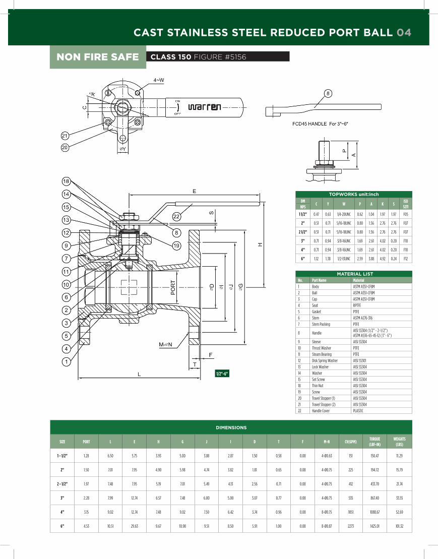
cast stainless steel Reduced poRt Ball 04
dimensions
SIZE pORT L E H g j I d T F M-N CV(gpM)TORQUE(LBF-IN)
WEIgHTS(LBS)
1 - 1/2” 1.28 6.50 5.75 3.93 5.00 3.88 2.87 1.50 0.58 0.08 4-Ø0.63 151 150.47 11.29
2” 1.50 7.01 7.95 4.90 5.98 4.74 3.82 1.81 0.65 0.08 4-Ø0.75 225 194.72 15.79
2 - 1/2” 1.97 7.48 7.95 5.19 7.01 5.49 4.13 2.56 0.71 0.08 4-Ø0.75 412 433.70 21.74
3” 2.28 7.99 12.74 6.57 7.48 6.00 5.00 3.07 0.77 0.08 4-Ø0.75 535 867.40 33.55
4” 3.15 9.02 12.74 7.48 9.02 7.50 6.42 3.74 0.96 0.08 8-Ø0.75 1051 1088.67 52.69
6” 4.53 10.51 29.63 9.67 10.98 9.51 8.50 5.91 1.00 0.08 8-Ø0.87 2273 1425.01 101.32
class 150 Figure #5156
mateRial listNo. part Name Material
1 Body ASTM A351-CF8M
2 Ball ASTM A351-CF8M
3 Cap ASTM A351-CF8M
4 Seat RPTFE
5 Gasket PTFE
6 Stem ASTM A276-316
7 Stem Packing PTFE
8 HandleAISI SS304 (1/2” ~ 2-1/2”)ASTM A536-65-45-12 ( 3”~ 6”)
9 Sleeve AISI SS304
10 Thrust Washer PTFE
11 Steam Bearing PTFE
12 Disk Spring Washer AISI SS301
13 Lock Washer AISI SS304
14 Washer AISI SS304
15 Set Screw AISI SS304
18 Thin Nut AISI SS304
19 Screw AISI SS304
20 Travel Stopper (1) AISI SS304
21 Travel Stopper (2) AISI SS304
22 Handle Cover PLASTIC
topWoRks unit:inch
dMC Y W p A K S
ISO 5211NpS
1 1/2” 0.47 0.63 1/4-20UNC 0.62 1.04 1.97 1.97 F05
2” 0.51 0.71 5/16-18UNC 0.80 1.56 2.76 2.76 F07
2 1/2” 0.51 0.71 5/16-18UNC 0.80 1.56 2.76 2.76 F07
3” 0.71 0.94 3/8-16UNC 1.69 2.61 4.02 0.20 F10
4” 0.71 0.94 3/8-16UNC 1.69 2.61 4.02 0.20 F10
6” 1.12 1.38 1/2-13UNC 2.59 3.88 4.92 0.24 F12
1/2"-6"
non Fire saFe
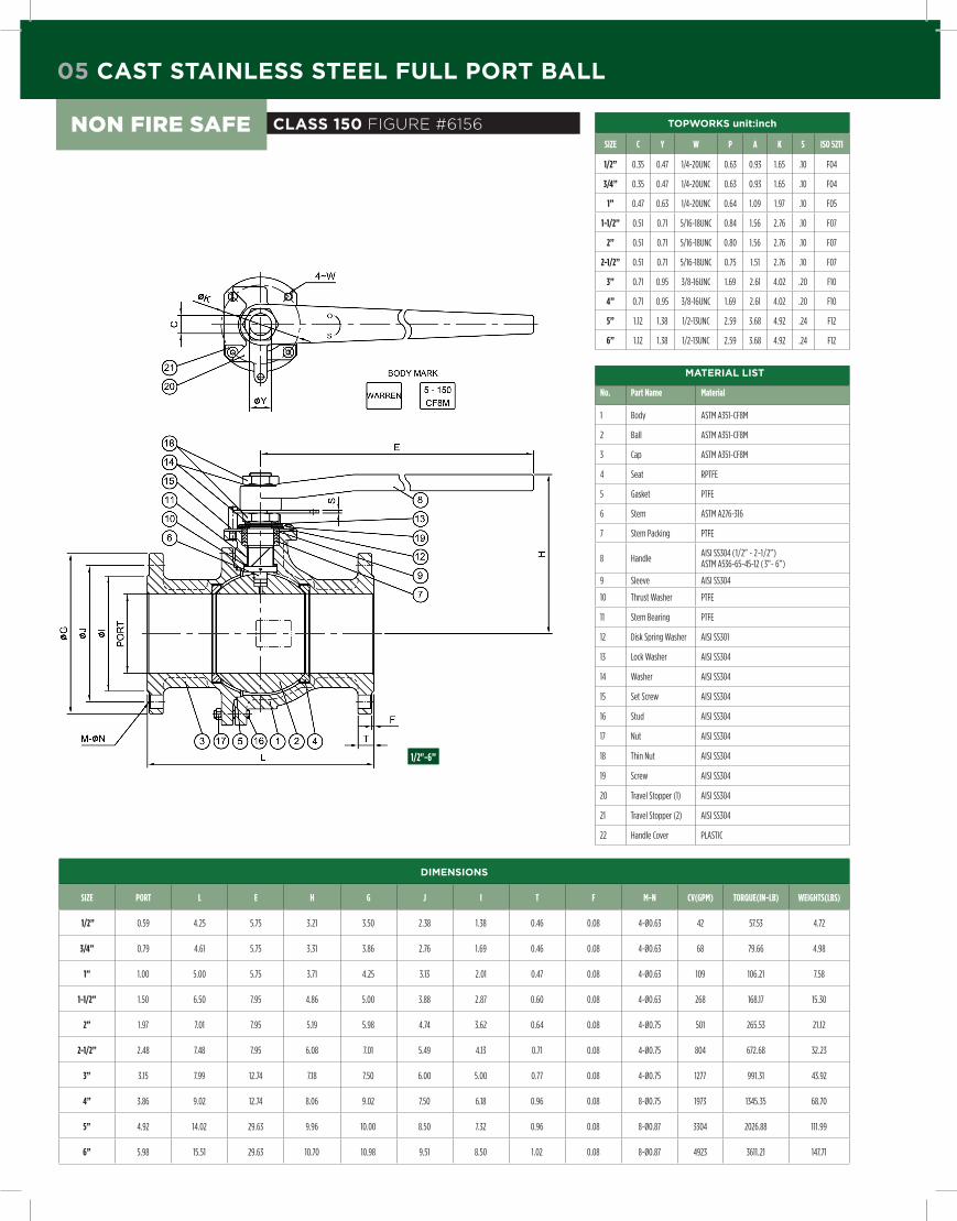
05 cast stainless steel Full poRt Ball
class 150 Figure #6156
dimensions
SIZE pORT L E H g j I T F M-N CV(gpM) TORQUE(IN-LB) WEIgHTS(LBS)
1/2” 0.59 4.25 5.75 3.21 3.50 2.38 1.38 0.46 0.08 4-Ø0.63 42 57.53 4.72
3/4” 0.79 4.61 5.75 3.31 3.86 2.76 1.69 0.46 0.08 4-Ø0.63 68 79.66 4.98
1” 1.00 5.00 5.75 3.71 4.25 3.13 2.01 0.47 0.08 4-Ø0.63 109 106.21 7.58
1-1/2” 1.50 6.50 7.95 4.86 5.00 3.88 2.87 0.60 0.08 4-Ø0.63 268 168.17 15.30
2” 1.97 7.01 7.95 5.19 5.98 4.74 3.62 0.64 0.08 4-Ø0.75 501 265.53 21.12
2-1/2” 2.48 7.48 7.95 6.08 7.01 5.49 4.13 0.71 0.08 4-Ø0.75 804 672.68 32.23
3” 3.15 7.99 12.74 7.18 7.50 6.00 5.00 0.77 0.08 4-Ø0.75 1277 991.31 43.92
4” 3.86 9.02 12.74 8.06 9.02 7.50 6.18 0.96 0.08 8-Ø0.75 1973 1345.35 68.70
5” 4.92 14.02 29.63 9.96 10.00 8.50 7.32 0.96 0.08 8-Ø0.87 3304 2026.88 111.99
6” 5.98 15.51 29.63 10.70 10.98 9.51 8.50 1.02 0.08 8-Ø0.87 4923 3611.21 147.71
1/2"-6”
topWoRks unit:inch
SIZE C Y W p A K S ISO 5211
1/2” 0.35 0.47 1/4-20UNC 0.63 0.93 1.65 .10 F04
3/4” 0.35 0.47 1/4-20UNC 0.63 0.93 1.65 .10 F04
1” 0.47 0.63 1/4-20UNC 0.64 1.09 1.97 .10 F05
1-1/2” 0.51 0.71 5/16-18UNC 0.84 1.56 2.76 .10 F07
2” 0.51 0.71 5/16-18UNC 0.80 1.56 2.76 .10 F07
2-1/2” 0.51 0.71 5/16-18UNC 0.75 1.51 2.76 .10 F07
3” 0.71 0.95 3/8-16UNC 1.69 2.61 4.02 .20 F10
4” 0.71 0.95 3/8-16UNC 1.69 2.61 4.02 .20 F10
5” 1.12 1.38 1/2-13UNC 2.59 3.68 4.92 .24 F12
6” 1.12 1.38 1/2-13UNC 2.59 3.68 4.92 .24 F12
mateRial list
No. part Name Material
1 Body ASTM A351-CF8M
2 Ball ASTM A351-CF8M
3 Cap ASTM A351-CF8M
4 Seat RPTFE
5 Gasket PTFE
6 Stem ASTM A276-316
7 Stem Packing PTFE
8 HandleAISI SS304 (1/2” ~ 2-1/2”)ASTM A536-65-45-12 ( 3”~ 6”)
9 Sleeve AISI SS304
10 Thrust Washer PTFE
11 Stem Bearing PTFE
12 Disk Spring Washer AISI SS301
13 Lock Washer AISI SS304
14 Washer AISI SS304
15 Set Screw AISI SS304
16 Stud AISI SS304
17 Nut AISI SS304
18 Thin Nut AISI SS304
19 Screw AISI SS304
20 Travel Stopper (1) AISI SS304
21 Travel Stopper (2) AISI SS304
22 Handle Cover PLASTIC
non Fire saFe

class 150 Figure #5156Fs
topWoRks unit:inch
dMØd b A B ØC
M TAp
Ød ENpS
1 1/2” 0.55 0.31 2.56 1.97 1.97 1/4 1.38 2.56
2” 0.79 0.47 3.54 2.68 2.76 5/16 1.81 3.15
2 1/2” 0.79 0.47 3.54 2.68 2.76 5/16 1.81 3.15
3” 1.06 0.67 4.92 3.74 4.02 3/8 2.44 4.33
4” 1.06 0.67 4.92 3.74 4.02 3/8 2.44 4.33
6” 1.34 0.87 4.92 3.74 4.02 3/8 2.76 4.33
8” 1.73 1.02 6.02 4.58 4.92 1/2 - 4.65
10” 2.01 1.26 6.89 5.28 5.51 5/8 - 5.91
dMF g Q H1 H2 H3 H4 T
ISO 5211NpS
1 1/2” 1.26 1.93 3/8” 1.05 0.38 0.38 .04 0.35 F05
2” 1.42 2.36 3/8” 1.22 0.57 0.39 .04 0.39 F07
2 1/2” 1.42 2.36 3/8” 1.22 0.57 0.39 .04 0.47 F07
3” 2.28 3.31 1/2” 1.71 0.91 0.72 .04 0.47 F10
4” 2.28 3.31 1/2” 1.71 0.91 0.72 .04 0.47 F10
6” 2.28 3.31 1/2” 1.93 1.18 0.98 .04 0.63 F10
8” 2.56 3.54 1/2” 2.32 1.34 1.04 - 0.75 F12
10” 3.07 4.65 5/8” 2.87 1.65 1.34 - 0.79 F14
mateRial listNo. part Name Material Remarks
1 BODY A351-CF8M
4 CAP A351-CF8M
5 STEM A564-630
6 BALL A351-CF8M
10 GLAND A276-316
11 GLAND FLANGE A351-CF8
14 SEAT RING RTFE 15% Glass Filled
20A O-RING VITON
20B GASKET GRAPHITE
22 GLAND PACKINGEXPANDED GRAPHITE+CORROSION INHIBITOR
3” & Larger
Cup and cone design
25 THRUST WASHER RTFE
32 GLAND BOLT A193-B8
39 SET SCREW A193-B8 8” & Larger
48 SNAP RING A686-W1 Ni+Cr PLATED
61 VINYL COATED HANDLE A283-D 2” & Smaller
61B HANDLE A536 3” & Larger
61C HANDLE CARBON STEEL 8” & Larger
65 STOPPER A240-304
66 HANDLE GUIDE A216-WCB 8” & Larger
71 ANTI STATIC A276-316
88 LOCKING PLATE A240-304
89 LOCKING PLATE BOLT A193-B8
97 TOP BOLT A193-B8
98 TOP WASHER A240-304
dimensions
SIZEBORE FACE TO FACE
CENTER TO TOp
LENgTHEnD FlAngE
Ød1WEIgHTS
(LBS)TORQUE (IN-LB)
CV VALUES(gpM)
Od BCd Od OF RF THICK dEpTH NO & dIM.d L H W D C g T f n-h
1 - 1/2” 1.00 6.50 4.00 6.00 5.00 3.88 2.87 0.56 .06 4-.63 1.50 15.43 125 28
2” 1.50 7.00 5.00 9.00 6.00 4.75 3.62 0.62 .06 4-.75 2.00 20.94 218 84
2 - 1/2” 2.00 7.50 5.00 9.00 7.00 5.50 4.13 0.70 .06 4-.75 2.50 30.86 375 212
3” 2.32 8.00 5.43 14.70 7.50 6.00 5.00 0.75 .06 4-.75 3.00 37.48 485 202
4” 3.00 9.00 6.29 14.70 9.00 7.50 6.19 0.94 .06 8-.75 4.00 61.29 743 302
6” 4.01 10.50 7.04 17.70 11.00 9.50 8.50 1.00 .06 8-.88 6.00 103.62 1806 304
8” 5.67 11.50 11.61 23.60 13.50 11.75 10.62 1.12 .06 8-.88 8.00 169.76 3404 675
10” 7.40 13.00 14.00 31.50 16.00 14.25 12.75 1.19 .06 12-1.00 10.00 246.92 6704 1147
1 1/2"-10"
cast stainless steel Reduced poRt Ball 06
Fire saFe

07 cast stainless steel Full poRt Ball
topWoRks unit:inch
dMØd b A B ØC M UNC Ød E
NpS
1/2” 0.39 0.24 2.17 1.54 1.65 1/4-20 0.94 2.28
3/4” 0.39 0.24 2.17 1.54 1.65 1/4-20 0.94 2.28
1” 0.55 0.31 2.56 1.89 1.97 1/4-20 1.38 2.56
1 1/4” 0.55 0.31 2.56 1.89 1.97 1/4-20 1.38 2.56
1 1/2” 0.79 0.47 354 2.68 2.76 5/16-18 1.81 3.15
2” 0.79 0.47 3.54 2.68 2.76 5/16-18 1.81 3.15
2 1/2” 1.06 0.67 4.92 3.74 4.02 3/8-16 2.44 4.33
3” 1.06 0.67 4.92 3.74 4.02 3/8-16 2.44 4.33
4” 1.34 0.87 4.92 3.74 4.02 3/8-16 2.76 4.33
5” 1.73 1.02 5.91 4.57 4.92 1/2-13 - 4.65
6” 1.73 1.02 6.02 4.58 4.92 1/2-13 - 4.65
8” 2.01 1.26 6.89 5.28 5.51 5/8-11 - 5.91
10” 1.97 1.50 8.27 6.50 6.50 3/4-10 - 5.91
dMF g Q H1 H2 H3 H4 T
ISO 5211NpS
1/2” 0.94 1.65 5/16 0.75 0.37 - .04 0.28 F04
3/4” 0.94 1.65 5/16 0.75 0.37 - .04 0.31 F04
1” 1.26 1.93 5/16 0.85 0.38 - .04 0.35 F05
1 1/4” 1.26 1.93 5/16 0.85 0.38 - .04 0.35 F05
1 1/2” 1.42 2.63 3/8 1.22 0.57 0.39 .04 0.35 F07
2” 1.42 2.63 3/8 1.22 0.57 0.39 .04 0.35 F07
2 1/2” 2.28 3.31 1/2 1.71 0.91 0.72 .04 0.55 F10
3” 2.28 3.31 1/2 1.71 0.91 0.72 .04 0.47 F10
4” 2.28 3.31 1/2 1.93 1.18 0.98 .04 0.47 F10
5” 2.56 3.54 1/2 2.32 1.34 1.04 - 0.63 F12
6” 2.56 3.54 1/2 2.32 1.34 1.04 - 0.63 F12
8” 3.07 4.65 5/8 2.87 1.65 1.35 - 0.75 F14
10” 3.07 4.65 5/8 3.96 2.05 1.82 - 0.94 F16
mateRial listNo. part Name Material Remarks
1 BODY A351-CF8M
4 CAP A351-CF8M
5 STEM A564-630
6 BALL A351-CF8M A276-316 1/2” Only
10 GLAND A276-316
11 GLAND FLANGE A351-CF8
12 YOKE SS400Zn Plated
Painted black
14 SEAT RING RTFE 15% Glass Filled
20B GASKET SW316+GRAPHITE
22 GLAND PACKINGEXPANDED GRAPHITE+CORROSION INHIBITOR
2” & Larger
Cup and cone design
25 THRUST WASHER RTFE
30 CAP BOLT A193-B8M
31 CAP BOLT NUT A194-8M
32 GLAND BOLT A193-B8
33 YOKE BOLT A193-B8
39 SET SCREW A193-B8
48 SNAP RING A686-W11 1/2 & Larger + Ni+Cr PLATED
49 0-RING VITON Only size 10”
61 VINYL COATED HANDLE A283-D 2” & Smaller
61B HANDLE A536 2 1/2” & Larger
61C HANDLE CARBON STEEL
65 STOPPER A240-304
66 HANDLE GUIDE A216-WCB
71 ANTI STATIC A276-316
73 STEM BEARING PTFE Only size 10”
76 GLAND BEARING PTFE Only size 10”
88 LOCKING PLATE A240-304
89 LOCKING PLATE BOLT A193-B8
90 COUPLING A276-410 ENP
91 MOUNTING BOLT A193-B8
97 TOP BOLT A193-B8
98 TOP WASHER A240-304
100 KEY AISI1045
200 GEAR BOX A536
dimensions
SIZEBORE
FACE TO FACE
CENTER TO TOp
LENgTHEnD FlAngE
WEIgHT (LBS)
TORQUE (IN-LB)
CV VALUES(gpM)
Od BCd Od OF RF THICK dEpTH NO & dIM.d L H W D C g T f n-Øh
1/2” .51 4.25 3.70 5.10 3.50 2.38 1.38 .44 .06 4-.62 3.97 36 28
3/4” .75 4.61 3.89 5.10 3.88 2.75 1.69 .44 .06 4-.62 5.07 46 61
1” 1.00 5.00 4.01 6.10 4.25 3.12 2.00 .44 .06 4-.62 7.05 59 110
1 1/4” 1.25 5.50 4.40 6.10 4.62 3.50 2.50 .50 .06 4-.62 10.58 132 185
1 1/2” 1.50 6.50 5.00 9.10 5.00 3.88 2.88 .56 .06 4-.62 14.55 258 260
2” 2.00 7.00 5.31 9.10 6.00 4.75 3.62 .62 .06 4-.75 21.61 373 505
2 1/2” 2.50 7.50 5.70 14.70 7.0 5.50 4.12 .69 .06 4-.75 34.83 754 817
3” 3.00 8.00 6.29 14.70 7.50 6.00 5.00 .75 .06 4-.75 46.96 1135 1152
4” 4.00 9.00 7.55 17.70 9.00 7.50 6.19 .94 .06 4-.75 76.50 1445 2135
5” 5.00 13.90 11.41 23.60 10.00 8.50 7.31 .94 .06 8-.88 134.48 3467 3412
6” 6.00 15.50 12.20 23.60 11.00 9.50 8.50 1.00 .06 8-.88 163.14 4333 5048
8” 8.00 18.00 14.56 31.50 13.50 11.75 10.62 1.12 .06 8-.88 288.81 7633 9319
10” 10.00 21.00 18.89 39.37 16.00 14.25 12.75 1.19 .06 12-1.00 454.15 16089 14590
DiMEnSionS For 6156FS with gEArbox
6” 6.00 15.50 12.20 15.75 11.00 9.50 8.50 1.00 .06 8-.88 163.14 4333 5048
8” 8.00 18.00 14.80 19.69 13.50 11.75 10.62 1.12 .06 8-.88 288.81 7633 9319
10” 10.00 21.00 19.96 27.95 16.00 14.25 12.75 1.19 .06 12-1.00 454.15 16089 14590
1/2"-4"
5"-10" 6"-10" with gearbox
class 150 Figure #6156FsFire saFe

cast stainless steel Reduced poRt Ball 08
dimensions
SIZEBORE FACE TO FACE
CENTER TO TOp
LENgTHEnD FlAngE
Ød1WEIgHTS
(LBS)TORQUE (IN-LB)
CV VALUES(gpM)
Od BCd Od OF RF THICK dEpTH NO & dIM.d L H W D C g T f n-h
1 - 1/2” 1.00 7.50 5.00 6.00 6.10 4.50 2.87 0.81 .06 4-.87 1.50 19.84 186 30
2” 1.50 8.50 5.00 9.00 6.50 5.00 3.62 0.88 .06 8-.75 2.00 26.46 682 106
3” 2.32 11.10 5.43 14.70 8.30 6.80 5.00 1.12 .06 8-.87 3.00 55.12 1186 285
4” 3.00 12.00 6.29 14.70 10.00 7.90 6.19 1.25 .06 8-.87 4.00 88.18 2212 386
6” 4.01 15.90 7.04 17.70 12.50 10.60 8.50 1.50 .06 12-.87 6.00 154.87 2950 418
8” 5.67 16.50 11.61 23.60 15.00 13.00 10.62 1.62 .06 12-.96 8.00 330.69 9767 890
10” 7.40 18.00 14.00 31.50 17.48 15.60 12.80 1.89 .06 16-1.12 10.0 469.58 12699 1939
topWoRks unit:inch
dMØd b A B ØC M TAp Ød E
NpS
1 1/2” 0.55 0.31 2.56 1.97 1.97 1/4 1.38 2.56
2” 0.79 0.47 3.54 2.68 2.76 5/16 1.81 3.15
3” 1.06 0.67 4.92 3.74 4.02 3/8 2.44 4.33
4” 1.06 0.67 4.92 3.74 4.02 3/8 2.44 4.33
6” 1.34 0.87 4.92 3.74 4.02 3/8 2.76 4.33
8” 1.73 1.02 6.02 4.58 4.92 1/2 - 4.65
10” 2.01 1.26 6.89 5.28 5.51 5/8 - 5.91
dMF g Q H1 H2 H3 H4 T
ISO 5211NpS
1 1/2” 1.26 1.93 3/8” 1.05 0.38 0.38 .04 0.35 F05
2” 1.42 2.36 3/8” 1.22 0.57 0.39 .04 0.39 F07
3” 2.28 3.31 1/2” 1.71 0.91 0.72 .04 0.47 F10
4” 2.28 3.31 1/2” 1.71 0.91 0.72 .04 0.47 F10
6” 2.28 3.31 1/2” 1.93 1.18 0.98 .04 0.63 F10
8” 2.56 3.54 1/2” 2.32 1.34 1.04 - 0.75 F12
10” 3.07 4.65 5/8” 2.87 1.65 1.34 - 0.79 F14
mateRial listNo. part Name Material Remarks
1 BODY A351-CF8M
4 CAP A351-CF8M
5 STEM A564-630
6 BALL A351-CF8M
10 GLAND A276-316
11 GLAND FLANGE A351-CF8
14 SEAT RING RTFE 15% Glass Filled
20A O-RING VITON
20B GASKET GRAPHITE
22 GLAND PACKINGEXPANDED GRAPHITE+CORROSION INHIBITOR
3” & Larger
Cup and cone design
25 THRUST WASHER RTFE
32 GLAND BOLT A193-B8
39 SET SCREW A193-B8 8” & Larger
48 SNAP RING A686-W1 Ni+Cr PLATED
61 VINYL COATED HANDLE A283-D 2” & Smaller
61B HANDLE A536 3” & Larger
61C HANDLE CARBON STEEL 8” & Larger
65 STOPPER A240-304
66 HANDLE GUIDE A216-WCB 8” & Larger
71 ANTI STATIC A276-316
88 LOCKING PLATE A240-304
89 LOCKING PLATE BOLT A193-B8
97 TOP BOLT A193-B8
98 TOP WASHER A240-304
1 1/2"-10"
class 300 Figure #5306FsFire saFe

dimensions
SIZEBORE
FACE TO FACE
CENTER TO TOp
LENgTHEnD FlAngE
WEIgHT (LBS)
TORQUE (IN-LB)
CV VALUES(gpM)
Od BCd Od OF RF THICK dEpTH NO & dIM.d L H W D C g T f n-Øh
1/2” .51 5.50 3.70 5.10 3.75 2.62 1.38 .56 .06 4-.62 5.29 48 28
3/4” .75 6.00 3.89 5.10 4.62 3.25 1.69 .62 .06 4-.75 7.94 63 61
1” 1.00 6.50 4.01 6.10 4.88 3.50 2.00 .69 .06 4-.75 11.24 79 110
1 1/4” 1.00 7.00 4.40 6.10 5.25 3.88 2.50 .75 .06 4-.75 15.87 221 185
1 1/2” 1.50 7.50 5.19 9.10 6.12 4.50 2.88 .81 .06 4-.88 23.81 496 260
2” 2.00 8.50 5.31 9.10 6.50 5.00 3.62 .88 .06 8-.75 31.31 743 505
2 1/2” 2.50 9.50 5.70 14.70 7.50 5.88 4.12 1.00 .06 8-.88 46.74 1422 817
3” 3.00 11.12 6.57 14.70 8.25 6.62 5.00 1.12 .06 8-.88 62.83 1770 1152
4” 4.00 12.00 7.71 17.70 10.0 7.88 6.19 1.25 .06 8-.88 110.45 2484 2135
6” 6.00 15.86 12.20 23.60 12.50 10.62 8.50 1.44 .06 12-.88 227.08 7014 5048
8” 8.00 19.75 14.56 31.50 15.00 13.00 10.62 1.62 .06 12-1.00 385.81 15470 9319
DiMEnSionS For 6306FS with gEArbox
6” 6.00 15.86 12.20 15.75 12.50 10.62 8.50 1.44 .06 12-.88 227.08 7014 5048
8” 8.00 19.75 14.80 19.69 15.00 13.00 10.62 1.62 .06 12-1.00 385.81 15470 9319
09 cast stainless steel Full poRt Ball
topWoRks unit:inch
dMØd b A B ØC M UNC Ød E
NpS
1/2” 0.39 0.24 2.17 1.54 1.65 1/4-20 0.94 2.28
3/4” 0.39 0.24 2.17 1.54 1.65 1/4-20 0.94 2.28
1” 0.55 0.31 2.56 1.89 1.97 1/4-20 1.38 2.56
1 1/4” 0.55 0.31 2.56 1.89 1.97 1/4-20 1.38 2.56
1 1/2” 0.79 0.47 3.54 2.68 2.76 5/16-18 1.81 3.15
2” 0.79 0.47 3.54 2.68 2.76 5/16-18 1.81 3.15
2 1/2” 1.06 0.67 4.92 3.74 4.02 3/8-16 2.44 4.33
3” 1.06 0.67 4.92 3.74 4.02 3/8-16 2.44 4.33
4” 1.34 0.87 4.92 3.74 4.02 3/8-16 2.76 4.33
6” 1.73 1.02 6.02 4.58 4.92 1/2-13 - 4.65
8” 2.01 1.26 6.89 5.28 5.51 5/8-11 - 5.91
dMF g Q H1 H2 H3 H4 T
ISO 5211NpS
1/2” 0.94 1.65 5/16 0.75 0.37 - .04 0.28 F04
3/4” 0.94 1.65 5/16 0.75 0.37 - .04 0.31 F04
1” 1.26 1.93 5/16 0.85 0.38 - .04 0.35 F05
1 1/4” 1.26 1.93 5/16 0.85 0.38 - .04 0.35 F05
1 1/2” 1.42 2.36 3/8 1.22 0.57 0.39 .04 0.35 F07
2” 1.42 2.36 3/8 1.22 0.57 0.39 .04 0.35 F07
2 1/2” 2.28 3.31 1/2 1.71 0.91 0.72 .04 0.55 F10
3” 2.28 3.31 1/2 1.71 0.91 0.72 .04 0.47 F10
4” 2.28 3.31 1/2 1.93 1.18 0.98 .04 0.47 F10
6” 2.56 3.54 1/2 2.32 1.34 1.04 - 0.63 F12
8” 3.07 4.65 5/8 2.87 1.65 1.35 - 0.75 F14
mateRial listNo. part Name Material Remarks
1 BODY A351-CF8M
4 CAP A351-CF8M
5 STEM A564-630
6 BALL A351-CF8M A276-316 1/2” Only
10 GLAND A276-316
11 GLAND FLANGE A351-CF8
12 YOKE SS400Zn Plated
Painted black
14 SEAT RING RTFE 15% Glass Filled
20B GASKET SW316+GRAPHITE
22 GLAND PACKINGEXPANDED GRAPHITE+CORROSION INHIBITOR
2” & Larger
Cup and cone design
25 THRUST WASHER RTFE
30 CAP BOLT A193-B8M
31 CAP BOLT NUT A194-8M
32 GLAND BOLT A193-B8
33 YOKE BOLT A193-B8
39 SET SCREW A193-B8
48 SNAP RING A686-W11 1/2 & Larger + Ni+Cr PLATED
61 VINYL COATED HANDLE A283-D 2” & Smaller
61B HANDLE A536 2 1/2” & Larger
61C HANDLE CARBON STEEL
65 STOPPER A240-304
66 HANDLE GUIDE A216-WCB
71 ANTI STATIC A276-316
88 LOCKING PLATE A240-304
89 LOCKING PLATE BOLT A193-B8
90 COUPLING A276-410 ENP
91 MOUNTING BOLT A193-B8
97 TOP BOLT A193-B8
98 TOP WASHER A240-304
100 KEY AISI1045
200 GEAR BOX A536
1/2"-4"
6"-8" 6"-8" with gearbox
class 300 Figure #6306FsFire saFe

cast stainless steel Reduced poRt Ball 10
topWoRks unit:inch
dMØd b A B ØC M UNC E
NpS
2” 0.83 0.55 3.45 2.68 2.76 5/16 3.15
3” 0.83 0.55 3.54 2.68 2.76 5/16 3.15
4” 1.34 0.87 4.92 3.74 4.02 3/8 4.33
6” 1.73 1.02 6.02 4.57 4.92 1/2 4.65
8” 2.01 1.26 6.89 5.28 5.51 5/8 5.91
dMF g Q H1 H2 T ISO 5211
NpS
2” 1.46 2.36 3/8 1.36 0.63 0.43 F07
3” 1.46 2.36 3/8 1.44 0.63 0.43 F07
4” 2.28 3.31 1/2 1.91 1.19 0.59 F10
6” 2.56 3.54 1/2 2.20 1.26 0.71 F12
8” 3.07 4.65 5/8 2.80 1.65 0.75 F14
mateRial listNo. part Name Material Remarks
1 BODY A351-CF8M
4 CAP A351-CF8M
5 STEM A564-630
6 BALL A351-CF8M
10 GLAND RING A276-316
11 GLAND FLANGE A351-CF8
14 SEAT RING RTFE 15% Carbon Fiber
20B GASKET SPW316+GRAPHITE
20A O-RING VITON
22 GLAND PACKINGEXPANDED GRAPHITE+CORROSION INHIBITOR
Cup and cone design
25 THRUST WASHER RTFE
30 CAP BOLT A193-B8
31 CAP NUT A194-8M
32 GLAND BOLT A193-B8
39 SET SCREW A193-B8 SIZE 6” & 8”
48 SNAP RING A686-W14” & Larger Ni+Cr Plated
61A HANDLE A283-D SIZE 3”
61B HANDLE A536 SIZE 4”
61C HANDLE Carbon Steel SIZE 6” & 8”
62 HANDLE GUIDE A536 SIZE 6” & 8”
65 STOPPER A240-304
71 ANTI STATIC A276-316
88 LOCKING PLATE A240-304
89 LOCKING BOLT A193-B8
97 TOP BOLT A276-304
98 TOP WASHER A240-304
dimensions
SIZEFLOW pASSAgE dIAMETER FACE TO FACE
CENTER TO TOp
dIAMETER OF HANdLE
EnD FlAngEWEIgHTS
(LBS)TORQUE (IN-LB)
CV VALUES(gpM)
OddIA OF BOLT
CIRCLEOd OF RF
THICKNESS MIN.
THICKNESS OF RF
BOLT HOLE NO. & dIA
d d1 L H W D C g T f n-h
2” 1.5 2.0 11.50 5.55 14.56 6.50 5.00 3.62 1.00 0.25 8-.75 37.48 1005 106
3” 2.0 3.0 14.01 6.25 14.57 8.25 6.62 5.00 1.25 0.25 8-.88 63.93 1572 285
4” 3.0 4.0 17.00 7.75 17.71 10.75 8.50 6.19 1.50 0.25 8-1.00 121.25 2652 386
6” 4.0 6.0 22.00 9.44 23.62 14.00 11.50 8.50 1.88 0.25 12-1.12 255.74 5316 418
8” 6.0 8.0 26.00 11.65 31.49 16.50 13.74 10.63 2.22 0.25 12-1.25 440.92 10835 890
2"
3"-8"
class 600 Figure #5606FsFire saFe

11 cast stainless steel Full poRt Ball
topWoRks unit:inch
dMØd b A B ØC M UNC E
NpS
1/2” 0.59 0.39 2.56 1.85 1.97 1/4 2.52
3/4” 0.59 0.39 2.56 1.89 1.97 1/4 2.52
1” 0.59 0.39 2.56 1.89 1.97 1/4 2.52
1 1/2” 0.83 0.55 3.54 2.68 2.76 5/16 3.15
2” 0.83 0.55 3.54 2.68 2.76 5/16 3.15
3” 1.34 0.87 4.92 3.74 4.02 3/8 4.33
4” 1.73 1.02 6.02 4.57 4.92 1/2 4.65
6” 2.01 1.26 6.89 5.28 5.51 5/8 5.91
dMF g Q H1 H2 T
ISO 5211NpS
1/2” 1.26 1.89 5/16 0.98 0.37 0.35 F05
3/4” 1.26 1.89 5/16 0.98 0.37 0.35 F05
1” 1.26 1.89 5/16 1.08 0.39 0.35 F05
1 1/2” 1.46 2.36 3/8 1.36 0.63 0.43 F07
2” 1.46 2.36 3/8 1.44 0.63 0.43 F07
3” 2.28 3.31 1/2 1.91 1.19 0.59 F10
4” 2.56 3.54 1/2 2.20 1.26 0.71 F12
6” 3.07 4.65 5/8 2.80 1.65 0.75 F14
mateRial listNo. part Name Material Remarks
1 BODY A351-CF8M
4 CAP A351-CF8M
5 STEM A564-630
6 BALL A351-CF8M
10 GLAND A276-316
11 GLAND FLANGE A351-CF8
14 SEAT RING RTFE 15% Carbon Fiber
20B GASKET SW316+GRAPHITE
20A O-RING VITON
22 GLAND PACKINGEXPANDED GRAPHITE+CORROSION INHIBITOR
2” & Larger
Cup and cone design
25 THRUST WASHER RTFE
30 CAP BOLT A193-B8M
31 CAP NUT A194-8M
32 GLAND BOLT A193-B8
39 SET SCREW A193-B8 Size 4” & 6”
48 SNAP RING A686-W13” & Larger + Ni+Cr PLATED
61 VINYL COATED HANDLE A283-D
61A HANDLE A283-D Only 2”
61B HANDLE A536 Only 3”
61C HANDLE CARBON STEEL Size 4” & 6”
62 HANDLE GUIDE A536 Size 4” & 6”
65 STOPPER A240-304
71 ANTI STATIC A276-316
88 LOCKING PLATE A240-304
89 LOCKING PLATE BOLT A193-B8
97 TOP BOLT A276-304
98 TOP WASHER A240-304
dimensions
SIZEBORE
FACE TO FACE
CENTER TO TOp
LENgTHEnD FlAngE
WEIgHT (LBS)
TORQUE (IN-LB)
CV VALUES(gpM)
Od BCd Od OF RF THICK dEpTH NO & dIM.d L H W D C g T f n-Øh
1/2” 0.51 6.50 3.85 9.64 3.75 2.65 1.38 0.56 0.25 4-0.62 8.49 174 28
3/4” 0.75 7.50 4.17 9367 4.62 3.25 1.69 0.62 0.25 4-0.75 14.55 269 61
1” 1.00 8.50 4.56 9.67 4.88 3.50 2.00 0.69 0.25 4-0.75 18.30 475 110
1 1/2” 1.50 9.50 5.55 14.56 6.12 4.50 2.88 0.88 0.25 4-0.88 34.61 1005 260
2” 2.00 11.50 6.25 14.57 6.50 5.00 3.62 1.00 0.25 8-0.75 74.96 1572 505
3” 3.00 14.01 7.75 17.71 8.25 6.62 5.00 1.25 0.25 8-0.88 132.28 2652 1152
4” 4.00 17.00 9.44 23.62 10.75 8.50 6.19 1.50 0.25 8-1.0 242.51 5316 2135
6” 6.00 22.00 11.65 31.49 14.00 11.50 8.50 1.88 0.25 12-1.12 443.13 14700 5048
1/2"-1 1/2"
2"-6"
class 600 Figure #6606FsFire saFe

cast caRBon steel 12
Cast Carbon steel raised Face Flanged ball Valves
Warren Valve’s line of Cast Carbon Steel
raised Face Flanged ball Valves is available
in reduced or Full Port. The floating design
is Fire Safe to API 607 and offered in classes
150, 300, and 600.
Warren Valves are subject to rigorous
quality inspections. Our comprehensive
evaluation includes on-site audits, inspection
at the source, receiving inspections, and
destructive material testing. Mill test reports
are always available.
geneRal design standaRds
FIRE SAFE Cast Carbon Steel Raised Face Flanged Ball Valves
Design API 608
Testing API 598, API 6D 1
Fire Safe Tested API 607
NACE MRO-175-2003
Pressure Equipment Directive 23/97/EC CE-PED
Low Emissions 100 PPM or less
Pressure Temperature Rating ANSI B16.34
Face to Face Dimensions ANSI B16.10
End Flange Dimensions ANSI B16.5
Visual Inspection of Castings MSS-SP-55
Standard Markings MSS-SP-25
1 Every Warren Valve is 100% pressure tested according to API
598 & API 6D requirements. MTrs are available upon request.
Features
locking Device
ISO 5211 Mounting Pad
Anti Static Device
Fire Safe to API 607 4th Edition
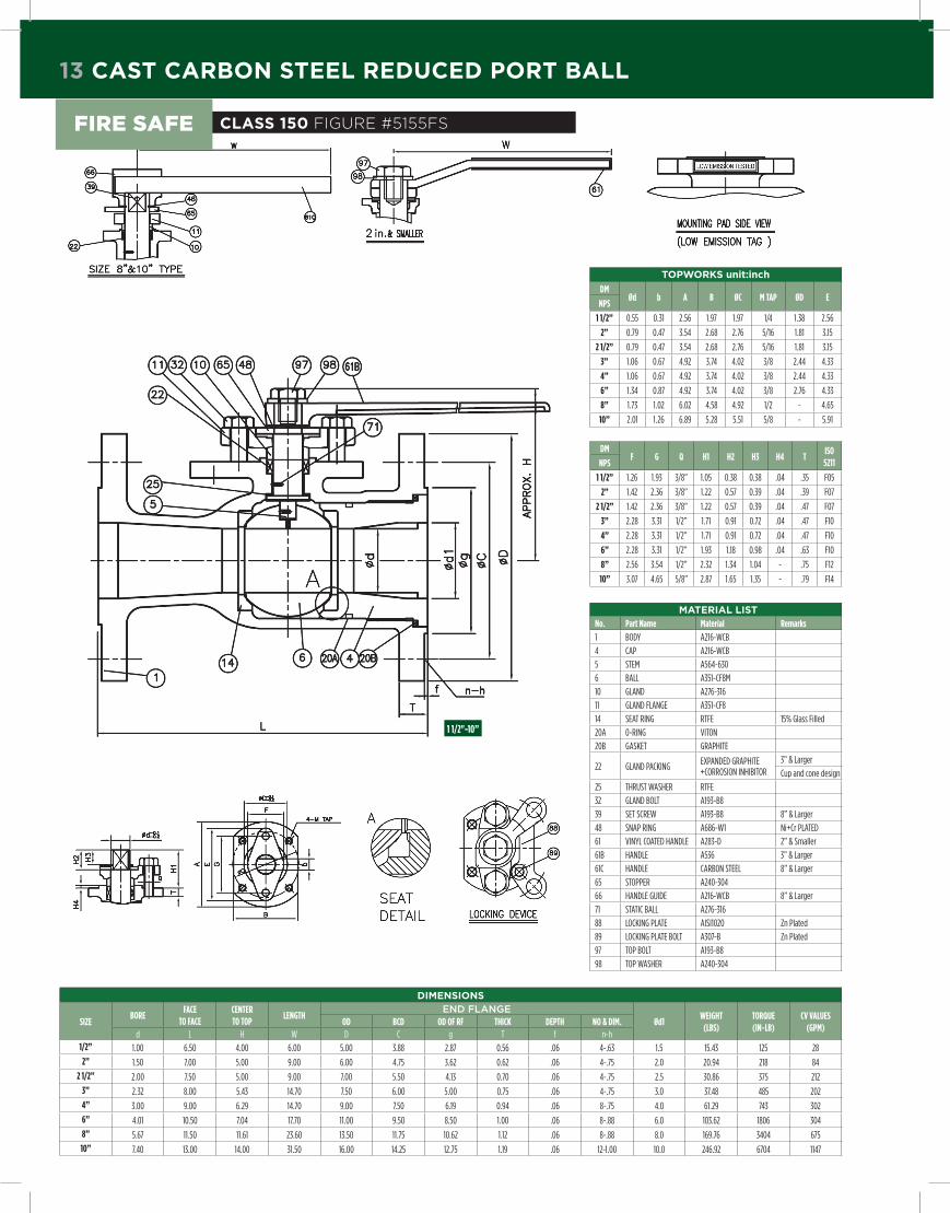
13 cast caRBon steel Reduced poRt Ball
topWoRks unit:inch
dMØd b A B ØC M TAp Ød E
NpS
1 1/2” 0.55 0.31 2.56 1.97 1.97 1/4 1.38 2.56
2” 0.79 0.47 3.54 2.68 2.76 5/16 1.81 3.15
2 1/2” 0.79 0.47 3.54 2.68 2.76 5/16 1.81 3.15
3” 1.06 0.67 4.92 3.74 4.02 3/8 2.44 4.33
4” 1.06 0.67 4.92 3.74 4.02 3/8 2.44 4.33
6” 1.34 0.87 4.92 3.74 4.02 3/8 2.76 4.33
8” 1.73 1.02 6.02 4.58 4.92 1/2 - 4.65
10” 2.01 1.26 6.89 5.28 5.51 5/8 - 5.91
mateRial listNo. part Name Material Remarks
1 BODY A216-WCB
4 CAP A216-WCB
5 STEM A564-630
6 BALL A351-CF8M
10 GLAND A276-316
11 GLAND FLANGE A351-CF8
14 SEAT RING RTFE 15% Glass Filled
20A 0-RING VITON
20B GASKET GRAPHITE
22 GLAND PACKINGEXPANDED GRAPHITE+CORROSION INHIBITOR
3” & Larger
Cup and cone design
25 THRUST WASHER RTFE
32 GLAND BOLT A193-B8
39 SET SCREW A193-B8 8” & Larger
48 SNAP RING A686-W1 Ni+Cr PLATED
61 VINYL COATED HANDLE A283-D 2” & Smaller
61B HANDLE A536 3” & Larger
61C HANDLE CARBON STEEL 8” & Larger
65 STOPPER A240-304
66 HANDLE GUIDE A216-WCB 8” & Larger
71 STATIC BALL A276-316
88 LOCKING PLATE AISI1020 Zn Plated
89 LOCKING PLATE BOLT A307-B Zn Plated
97 TOP BOLT A193-B8
98 TOP WASHER A240-304
dMF g Q H1 H2 H3 H4 T
ISO 5211NpS
1 1/2” 1.26 1.93 3/8” 1.05 0.38 0.38 .04 .35 F05
2” 1.42 2.36 3/8” 1.22 0.57 0.39 .04 .39 F07
2 1/2” 1.42 2.36 3/8” 1.22 0.57 0.39 .04 .47 F07
3” 2.28 3.31 1/2” 1.71 0.91 0.72 .04 .47 F10
4” 2.28 3.31 1/2” 1.71 0.91 0.72 .04 .47 F10
6” 2.28 3.31 1/2” 1.93 1.18 0.98 .04 .63 F10
8” 2.56 3.54 1/2” 2.32 1.34 1.04 - .75 F12
10” 3.07 4.65 5/8” 2.87 1.65 1.35 - .79 F14
dimensions
SIZEBORE
FACE TO FACE
CENTER TO TOp
LENgTHEnD FlAngE
Ød1WEIgHT
(LBS)TORQUE (IN-LB)
CV VALUES(gpM)
Od BCd Od OF RF THICK dEpTH NO & dIM.d L H W D C g T f n-h
1/2” 1.00 6.50 4.00 6.00 5.00 3.88 2.87 0.56 .06 4-.63 1.5 15.43 125 28
2” 1.50 7.00 5.00 9.00 6.00 4.75 3.62 0.62 .06 4-.75 2.0 20.94 218 84
2 1/2” 2.00 7.50 5.00 9.00 7.00 5.50 4.13 0.70 .06 4-.75 2.5 30.86 375 212
3” 2.32 8.00 5.43 14.70 7.50 6.00 5.00 0.75 .06 4-.75 3.0 37.48 485 202
4” 3.00 9.00 6.29 14.70 9.00 7.50 6.19 0.94 .06 8-.75 4.0 61.29 743 302
6” 4.01 10.50 7.04 17.70 11.00 9.50 8.50 1.00 .06 8-.88 6.0 103.62 1806 304
8” 5.67 11.50 11.61 23.60 13.50 11.75 10.62 1.12 .06 8-.88 8.0 169.76 3404 675
10” 7.40 13.00 14.00 31.50 16.00 14.25 12.75 1.19 .06 12-1.00 10.0 246.92 6704 1147
1 1/2"-10”
class 150 Figure #5155FsFire saFe

cast caRBon steel Full poRt Ball 14
topWoRks unit:inch
dMØd b A B ØC M UNC Ød E
NpS
1/2” 0.39 0.24 2.17 1.54 1.65 1/4-20 0.94 2.28
3/4” 0.39 0.24 2.17 1.54 1.65 1/4-20 0.94 2.28
1” 0.55 0.31 2.56 1.89 1.97 1/4-20 1.38 2.56
1 1/4” 0.55 0.31 2.56 1.89 1.97 1/4-20 1.38 2.56
1 1/2” 0.79 0.47 3.54 2.68 2.76 5/16-18 1.81 3.15
2” 0.79 0.47 3.54 2.68 2.76 5/16-18 1.81 3.15
2 1/2” 1.06 0.67 4.92 3.74 4.02 3/8-16 2.44 4.33
3” 1.06 0.67 4.92 3.74 4.02 3/8-16 2.44 4.33
4” 1.34 0.87 4.92 3.74 4.02 3/8-16 2.76 4.33
5” 1.73 1.02 5.91 4.57 4.92 1/2-13 - 4.65
6” 1.73 1.02 6.02 4.58 4.92 1/2-13 - 4.65
8” 2.01 1.26 6.89 5.28 5.51 5/8-11 - 5.91
10” 1.97 1.50 8.27 6.50 6.50 3/4-10 - 5.91
dMF g Q H1 H2 H3 H4 T
ISO 5211NpS
1/2” .94 1.65 5/16 0.75 0.37 - .04 0.28 F04
3/4” .94 1.65 5/16 0.75 0.37 - .04 0.31 F04
1” 1.26 1.93 5/16 0.85 0.38 - .04 0.35 F05
1 1/4” 1.26 1.93 5/16 0.85 0.38 - .04 0.35 F05
1 1/2” 1.42 2.36 3/8 1.22 0.57 0.39 .04 0.35 F07
2” 1.42 2.36 3/8 1.22 0.57 0.39 .04 0.35 F07
2 1/2” 2.28 3.31 1/2 1.71 0.91 0.72 .04 0.55 F10
3” 2.28 3.31 1/2 1.71 0.91 0.72 .04 0.47 F10
4” 2.28 3.31 1/2 1.93 1.18 0.98 .04 0.47 F10
5” 2.56 3.54 1/2 2.32 1.34 1.04 - 0.63 F12
6” 2.56 3.54 1/2 2.32 1.34 1.04 - 0.63 F12
8” 3.07 4.65 5/8 2.87 1.65 1.35 - 0.75 F14
10” 3.07 4.65 5/8 3.96 2.05 1.82 - 0.94 F16
mateRial listNo. part Name Material Remarks
1 BODY A216-WCB
4 CAP A216-WCB
5 STEM A564-630
6 BALL A351-CF8M A276-316 1/2” Only
10 GLAND A276-316
11 GLAND FLANGE A351-CF8
12 YOKE SS400Zn Plated
Painted black
14 SEAT RING RTFE 15% Glass Filled
20B GASKET SW316+GRAPHITE
22 GLAND PACKINGEXPANDED GRAPHITE+CORROSION INHIBITOR
2” & Larger
Cup and cone design
25 THRUST WASHER RTFE
30 CAP BOLT A193-B7M
31 CAP BOLT NUT A194-2HM
32 GLAND BOLT A193-B8
33 YOKE BOLT A193-B8
39 SET SCREW A193-B8
48 SNAP RING A686-W11 1/2 & Larger + Ni+Cr PLATED
49 O-RING VITON Only size 10”
61 VINYL COATED HANDLE A283-D 2” & Smaller
61B HANDLE A536 2 1/2” & Larger
61C HANDLE CARBON STEEL
65 STOPPER A240-304
66 HANDLE GUIDE A216-WCB
71 ANTI STATIC A276-316
73 STEM BEARING PTFE Only size 10”
76 GLAND BEARING PTFE Only size 10”
88 LOCKING PLATE AISI1020 Zn Plated
89 LOCKING PLATE BOLT A307-B8 Zn Plated
90 COUPLING A276-410 ENP
91 MOUNTING BOLT A193-B8
97 TOP BOLT A193-B8
98 TOP WASHER A240-304
100 KEY AISI1045
200 GEAR BOX A536
dimensions
SIZEBORE
FACE TO FACE
CENTER TO TOp
LENgTHEnD FlAngE
WEIgHT (LBS)
TORQUE (IN-LB)
CV VALUES(gpM)
Od BCd Od OF RF THICK dEpTH NO & dIM.d L H W D C g T f n-Øh
1/2” .51 4.25 3.70 5.10 3.50 2.38 1.38 .44 .06 4-.62 3.97 36 28
3/4” .75 4.61 3.89 5.10 3.88 2.75 1.69 .44 .06 4-.62 5.07 46 611” 1.00 5.00 4.01 6.10 4.25 3.12 2.00 .44 .06 4-.62 7.05 59 110
1 1/4” 1.25 5.50 4.40 6.10 4.62 3.50 2.50 .50 .06 4-.62 10.58 132 185
1 1/2” 1.50 6.50 5.00 9.10 5.00 3.88 2.88 .56 .06 4-.62 14.55 258 260
2” 2.00 7.00 5.31 9.10 6.00 4.75 3.62 .62 .06 4-.75 21.61 373 505
2 1/2” 2.50 7.50 5.70 14.70 7.00 5.50 4.12 .69 .06 4-.75 34.83 754 817
3” 3.00 8.00 6.29 14.70 7.50 6.00 5.00 .75 .06 4-.75 46.96 1135 1152
4” 4.00 9.00 7.55 17.70 9.00 7.50 6.19 .94 .06 4-.75 76.50 1445 2135
5” 5.00 13.90 11.41 23.60 10.00 8.50 7.31 .94 .06 8-.88 134.48 3467 3412
6” 6.00 15.50 12.20 23.60 11.00 9.50 8.50 1.00 .06 8-.88 163.14 4333 5048
8” 8.00 18.00 14.56 31.50 13.50 11.75 10.62 1.12 .06 8-.88 288.81 7633 9319
10” 10.00 21.00 18.89 39.37 16.00 14.25 12.75 1.19 .06 12-1.00 454.15 16089 14590
DiMEnSionS For 6155FS with gEArbox
6” 6.00 15.50 12.20 15.75 11.00 9.50 8.50 1.00 .06 8-.88 163.14 4333 5048
8” 8.00 18.00 14.80 19.69 13.50 11.75 10.62 1.12 .06 8-.88 288.81 7633 9319
10” 10.00 21.00 19.96 27.95 16.00 14.25 12.75 1.19 .06 12-1.00 454.15 16089 14590
1/2”-4”
5”-10” 6"-10" with gearbox
class 150 Figure #6155FsFire saFe

15 cast caRBon Reduced poRt Ball
topWoRks unit:inch
dMØd b A B ØC M TAp Ød E
NpS
1 1/2” 0.55 0.31 2.56 1.97 1.97 1/4 1.38 2.56
2” 0.79 0.47 3.54 2.68 2.76 5/16 1.81 3.15
3” 1.06 0.67 4.92 3.74 4.02 3/8 2.44 4.33
4” 1.06 0.67 4.92 3.74 4.02 3/8 2.44 4.33
6” 1.34 0.87 4.92 3.74 4.02 3/8 2.76 4.33
8” 1.73 1.02 6.02 4.58 4.92 1/2 - 4.65
10” 2.01 1.26 6.89 5.28 5.51 5/8 - 5.91
dMF g Q H1 H2 H3 H4 T
ISO 5211NpS
1 1/2” 1.26 1.93 3/8” 1.05 0.38 0.38 .04 .35 F05
2” 1.42 2.36 3/8” 1.22 0.57 0.39 .04 .39 F07
3” 2.28 3.31 1/2” 1.71 0.91 0.72 .04 .47 F10
4” 2.28 3.31 1/2” 1.71 0.91 0.72 .04 .47 F10
6” 2.28 3.31 1/2” 1.93 1.18 0.98 .04 .63 F10
8” 2.56 3.54 1/2” 2.32 1.34 1.04 - .75 F12
10” 3.07 4.65 5/8” 2.87 1.65 1.35 - .79 F14
mateRial listNo. pART NAME Material Remarks
1 BODY A216-WCB
4 CAP A216-WCB
5 STEM A564-630
6 BALL A351-CF8M
10 GLAND A276-316
11 GLAND FLANGE A351-CF8
14 SEAT RING RTFE 15% Glass Filled
20A 0-RING VITON
20B GASKET GRAPHITE
22 GLAND PACKINGEXPANDED GRAPHITE+CORROSION INHIBITOR
3” & Larger
Cup and cone design
25 THRUST WASHER RTFE
32 GLAND BOLT A193-B8
39 SET SCREW A193-B8 8” & Larger
48 SNAP RING A686-W1 Ni+Cr PLATED
61 VINYL COATED HANDLE A283-D 2” & Smaller
61B HANDLE A536 3” & Larger
61C HANDLE CARBON STEEL 8” & Larger
65 STOPPER A240-304
66 HANDLE GUIDE A216-WCB 8” & Larger
71 ANTI STATIC A276-316
88 LOCKING PLATE AISI1020 Zn Plated
89 LOCKING PLATE BOLT A193-B Zn Plated
97 TOP BOLT A193-B8
98 TOP WASHER A240-304
dimensions
SIZEBORE
FACE TO FACE
CENTER TO TOp
LENgTHEnD FlAngE
WEIgHT (LBS)
TORQUE (IN-LB)
CV VALUES(gpM)
Od BCd Od OF RF THINK dEpTH NO & dIM.d L H W D C g T f n-h
1 1/2” 1.00 7.5 5.00 6.0 6.10 4.50 2.87 0.81 .06 4-.87 19.84 186 30
2” 1.50 8.5 5.00 9.0 6.50 5.00 3.62 0.88 .06 8-.75 26.46 682 106
3” 2.32 11.1 5.43 14.7 8.30 6.60 5.00 1.12 .06 8-.87 55.12 1186 285
4” 3.00 12.0 6.29 14.7 10.00 7.90 6.19 1.25 .06 8-.87 88.18 2212 386
6” 4.01 15.9 7.04 17.7 12.50 10.60 8.50 1.50 .06 12-.87 154.87 2950 416
8” 5.67 16.5 11.61 23.6 15.00 13.00 10.62 1.62 .06 12-.98 330.69 9767 890
10” 7.40 18.0 14.00 31.5 17.48 15.60 12.80 1.89 .06 15-1.12 469.58 12699 1939
1 1/2"-10”
class 300 Figure #5305FsFire saFe

cast caRBon steel Full poRt Ball 16
topWoRks unit:inch
dMØd b A B ØC M UNC Ød E
NpS
1/2” 0.39 0.24 2.17 1.54 1.65 1/4-20 0.94 2.28
3/4” 0.39 0.24 2.17 1.54 1.65 1/4-20 0.94 2.28
1” 0.55 0.31 2.56 1.89 1.97 1/4-20 1.38 2.56
1 1/4” 0.55 0.31 2.56 1.89 1.97 1/4-20 1.38 2.56
1 1/2” 0.79 0.47 3.54 2.68 2.76 5/16-18 1.81 3.15
2” 0.79 0.47 3.54 2.68 2.76 5/16-18 1.81 3.15
2 1/2” 1.06 0.67 4.92 3.74 4.02 3/8-16 2.44 4.33
3” 1.06 0.67 4.92 3.74 4.02 3/8-16 2.44 4.33
4” 1.34 0.87 4.92 3.74 4.02 3/8-16 2.76 4.33
6” 1.75 1.02 6.02 4.58 4.92 1/2-13 - 4.65
8” 2.01 1.26 6.89 5.28 5.51 5/8-11 - 5.91
dMF g Q H1 H2 H3 H4 T
ISO 5211NpS
1/2” 0.94 1.65 5/16 0.75 0.37 - .04 0.28 F04
3/4” 0.94 1.65 5/16 0.75 0.37 - .04 0.31 F04
1” 1.26 1.93 5/16 0.85 0.38 - .04 0.35 F05
1 1/4” 1.26 1.93 5/16 0.85 0.38 - .04 0.35 F05
1 1/2” 1.42 2.36 3/8 1.22 0.57 0.39 .04 0.35 F07
2” 1.42 2.36 3/8 1.22 0.57 0.39 .04 0.35 F07
2 1/2” 2.28 3.31 1/2 1.71 0.91 0.72 .04 0.55 F10
3” 2.28 3.31 1/2 1.71 0.91 0.72 .04 0.47 F10
4” 2.28 3.31 1/2 1.93 1.18 0.98 .04 0.47 F10
6” 2.56 3.54 1/2 2.32 1.34 1.04 - 0.63 F12
8” 3.07 4.65 5/8 2.87 1.65 1.35 - 0.75 F14
mateRial listNo. part Name Material Remarks
1 BODY A216-WCB
4 CAP A216-WCB
5 STEM A564-630
6 BALL A351-CF8M A276-316 1/2” Only
10 GLAND A276-316
11 GLAND FLANGE A351-CF8
12 YOKE SS400Zn Plated
Painted black
14 SEAT RING RTFE 15% Glass Filled
20B GASKET SW316+GRAPHITE
22 GLAND PACKINGEXPANDED GRAPHITE+CORROSION INHIBITOR
2” & Larger
Cup and cone design
25 THRUST WASHER RTFE
30 CAP BOLT A193-B7M
31 CAP BOLT NUT A194-2HM
32 GLAND BOLT A193-B8
33 YOKE BOLT A193-B8
39 SET SCREW A193-B8
48 SNAP RING A686-W11 1/2 & Larger + Ni+Cr PLATED
61 VINYL COATED HANDLE A283-D 2” & Smaller
61B HANDLE A536 2 1/2” & Larger
61C HANDLE CARBON STEEL
65 STOPPER A240-304
66 HANDLE GUIDE A216-WCB
71 ANTI STATIC A276-316
88 LOCKING PLATE AISI1020 Zn Plated
89 LOCKING PLATE BOLT A307-B Zn Plated
90 COUPLING A276-410 ENP
91 MOUNTING BOLT A193-B8
97 TOP BOLT A193-B8
98 TOP WASHER A240-304
100 KEY AISI1045
200 GEAR BOX A536
dimensions
SIZEBORE
FACE TO FACE
CENTER TO TOp
LENgTHEnD FlAngE
WEIgHT (LBS)
TORQUE (IN-LB)
CV VALUES(gpM)
Od BCd Od OF RF THICK dEpTH NO & dIM.d L H W D C g T f n-Øh
1/2” .51 5.50 3.70 5.10 3.75 2.62 1.38 .56 .06 4-.62 5.29 48 28
3/4” .75 6.00 3.89 5.10 4.62 3.25 1.69 .62 .06 4-.75 7.94 63 611” 1.00 6.50 4.01 6.10 4.88 3.50 2.00 .69 .06 4-.75 11.24 79 110
1 1/4” 1.00 7.00 4.40 6.10 5.25 3.88 2.50 .75 .06 4-.75 15.87 221 185
1 1/2” 1.50 7.50 5.19 9.10 6.12 4.50 2.88 .81 .06 4-.88 23.81 496 260
2” 2.00 8.50 5.31 9.10 6.50 5.00 3.62 .88 .06 8-.75 31.31 743 505
2 1/2” 2.50 9.50 5.70 14.70 7.50 5.88 4.12 1.00 .06 8-.88 46.74 1422 817
3” 3.00 11.12 6.57 14.70 8.25 6.62 5.00 1.12 .06 8-.88 62.83 1770 1152
4” 4.00 12.00 7.71 17.70 10.00 7.88 6.19 1.25 .06 8-.88 110.45 2484 2135
6” 6.00 15.86 12.20 23.60 12.50 10.62 8.50 1.44 .06 12-.88 227.08 7014 5048
8” 8.00 19.75 14.56 31.50 15.00 13.00 10.62 1.62 .06 12-1.00 385.81 15470 9319
DiMEnSionS For 6305FS with gEArbox
6” 6.00 15.86 12.20 15.75 12.50 10.62 8.50 1.44 .06 12-.88 227.08 7014 5048
8” 8.00 19.75 14.80 19.69 15.00 13.00 10.62 1.62 .06 12-1.00 385.81 15470 9319
1/2”-4”
6”-8” 6"-8" with gearbox
class 300 Figure #6305FsFire saFe

17 cast caRBon steel Reduced poRt Ball
topWoRks unit:inch
dMØd b A B ØC M UNC E
NpS
2” 0.83 0.55 3.54 2.68 2.76 5/16 3.15
3” 0.83 0.55 3.54 2.68 2.76 5/16 3.15
4” 1.34 0.87 4.92 3.74 4.02 3/8 4.33
6” 1.73 1.02 6.02 4.57 4.92 1/2 4.68
8” 2.01 1.26 6.89 5.28 5.51 5/8 5.91
dMF g Q H1 H2 T
ISO 5211NpS
2” 1.46 2.36 3/8 1.36 0.63 0.43 F07
3” 1.46 2.36 3/8 1.44 0.63 0.46 F07
4” 2.28 3.31 1/2 1.91 1.19 0.59 F10
6” 2.56 3.54 1/2 2.20 1.26 0.71 F12
8” 3.07 4.65 5/8 2.80 1.65 0.75 F14
mateRial listNo. part Name Material Remarks
1 BODY A216-WCB
4 CAP A216-WCB
5 STEM A564-630
6 BALL A351-CF8M
10 GLAND A276-316
11 GLAND FLANGE A351-CF8
14 SEAT RING RTFE 15% Carbon Fiber
20A 0-RING VITON
20B GASKET SPW316+GRAPHITE
22 GLAND PACKINGEXPANDED GRAPHITE+CORROSION INHIBITOR
Cup and cone design
25 THRUST WASHER RTFE
30 CAP BOLT A193-B7M
31 CAP NUT A194-2HM
32 GLAND BOLT A193-B8
39 SET SCREW A193-B8 8” & Larger
48 SNAP RING A686-W1Ni+Cr PLATED4” & Larger
61A HANDLE A283-D
61B HANDLE A536 Only 4”
61C HANDLE CARBON STEEL Size 6” & 8”
62 HANDLE GUIDE A536 Size 6” & 8”
65 STOPPER A240-304
71 ANTI STATIC A276-316
88 LOCKING PLATE AISI1020 Zn Plated
89 LOCKING PLATE BOLT A307-B Zn Plated
97 TOP BOLT A276-304
98 TOP WASHER A240-304
dimensions
SIZEFLOW pASSAgE dIAMETER
FACE TO FACE
CENTER TO TOp
dIAMETER OF HANdLE
EnD FlAngEWEIgHT
(LBS)TORQUE (IN-LB)
CV VALUE(gpM)
OddIA. OF BOLT
CIRCLEOd OF RF
THICKNESS MIN.
THICKNESS OF RF
BOLT HOLE NO. & dIA.
d d L H W D C g T f n-h2” 1.5 2.0 11.50 5.55 14.56 6.50 5.00 3.62 1.00 0.25 8-.75 37.48 1005 106
3” 2.0 3.0 14.01 6.25 14.57 8.25 6.62 5.00 1.25 0.25 8-.88 63.93 1572 285
4” 3.0 4.0 17.00 7.75 17.71 10.75 8.50 6.19 1.50 0.25 8-1.00 121.25 2652 356
6” 4.0 6.0 22.00 9.44 23.62 14.00 11.50 8.50 1.88 0.25 12-1.12 255.74 5316 418
8” 6.0 8.0 26.00 11.65 31.49 16.50 13.74 10.63 2.22 0.25 12-1.25 440.92 10835 890
3"-8”
2”
class 600 Figure #5605FsFire saFe

cast caRBon steel Full poRt Ball 18
topWoRks unit:inch
dMØd b A B ØC M UNC E
NpS
1/2” 0.59 0..39 2.56 1.85 1.97 1/4 2.52
3/4” 0.59 0.39 2.56 1.89 1.97 1/4 2.52
1” 0.59 0.39 2.56 1.89 1.97 1/4 2.52
1 1/2” 0.83 0.55 3.54 2.68 2.76 5/16 3.15
2” 0.83 0.55 3.54 2.68 2.76 5/16 3.15
3” 1.34 0.87 4.92 3.74 4.02 3/8 4.33
4” 1.73 1.02 6.02 4.57 4.92 1/2 4.65
6” 2.01 1.26 6.89 5.28 5.51 5/8 5.91
dMF g Q H1 H2 T
ISO 5211NpS
1/2” 1.26 1.89 5/16 0.98 0.37 0.35 F05
3/4” 1.26 1.89 5/16 0.98 0.37 0.35 F05
1” 1.26 1.89 5/16 1.08 0.39 0.35 F05
1 1/2” 1.46 2.36 3/8 1.36 0.63 0.43 F07
2” 1.46 2.36 3/8 1.44 0.63 0.43 F07
3” 2.28 3.31 1/2 1.91 1.19 0.59 F10
4” 2.56 3.54 1/2 2.20 1.26 0.71 F12
6” 3.07 4.65 5/8 2.80 1.65 0.75 F14
mateRial listNo. part Name Material Remarks
1 BODY A216-WCB
4 CAP A216-WCB
5 STEM A564-630
6 BALL A351-CF8M A276-316 1/2” Only
10 GLAND A276-316
11 GLAND FLANGE A351-CF8
14 SEAT RING RTFE 15% Carbon Fiber
20A O-RING VITON
20B GASKET SW316+GRAPHITE
22 GLAND PACKINGEXPANDED GRAPHITE+CORROSION INHIBITOR
Cup and cone design
25 THRUST WASHER RTFE
30 CAP BOLT A193-B7M
31 CAP NUT A194-2HM
32 GLAND BOLT A193-B8
39 SET SCREW A193-B8 Size 4” & 6”
48 SNAP RING A686-W13” & Larger + Ni+Cr PLATED
61 VINYL COATED HANDLE A283-D 2” & Smaller
61A HANDLE A283-D
61B HANDLE A536 Only 3”
61C HANDLE CARBON STEEL Size 4” & 6”
65 STOPPER A240-304
71 ANTI STATIC A276-316
88 LOCKING PLATE AISI1020 Zn Plated
89 LOCKING PLATE BOLT A307-B Zn Plated
97 TOP BOLT A276-304
98 TOP WASHER A240-304
dimensions
SIZEFLOW pASSAgE
dIAMETERFACE
TO FACECENTER TO TOp
dIA. OF HANdLE
EnD FlAngEWEIgHT
(LBS)TORQUE (IN-LB)
CV VALUES(gpM)
OddIA. OF BOLT
CIRCLEOd OF RF
THICKNESS MIN.
THICKNESS OF RF
BOLT HOLE NO. & dIAMETER
d L H W D C g T f n-Øh1/2” 0.51 6.50 3.85 9.64 3.75 2.65 1.38 0.56 0.25 4-0.62 8.49 174 28
3/4” 0.75 7.50 4.17 9.64 4.62 3.25 1.69 0.62 0.25 4-0.75 14.55 269 611” 1.00 8.50 4.56 9.64 4.88 3.50 2.00 0.69 0.25 4-0.75 18.30 475 110
1 1/2” 1.50 9.50 5.55 14.56 6.12 4.50 2.88 0.88 0.25 4-0.88 34.61 1005 260
2” 2.00 11.50 6.25 14.57 6.50 5.00 3.62 1.00 0.25 8-0.75 74.96 1572 505
3” 3.00 14.01 7.75 17.71 8.25 6.62 5.00 1.25 0.25 8-0.88 132.28 2652 1152
4” 4.00 17.00 9.44 23.62 10.75 8.50 6.19 1.50 0.25 8-1.00 242.51 5316 2135
6” 6.00 22.00 11.65 31.49 14.00 11.50 8.50 1.88 0.25 12-1.12 443.13 14700 5048
1/2”-1 1/2”
2”-6”
class 600 Figure #6605FsFire saFe
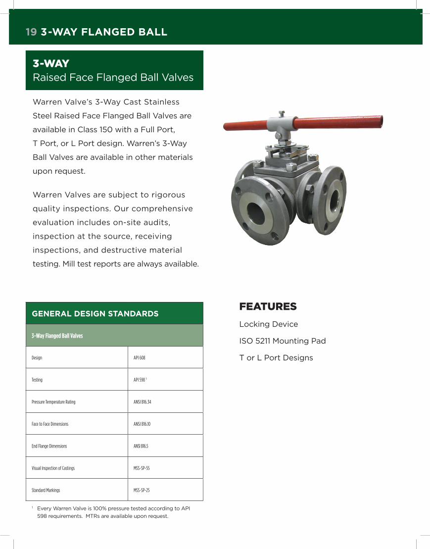
19 3-Way Flanged Ball
3-way raised Face Flanged ball Valves
Warren Valve’s 3-Way Cast Stainless
Steel raised Face Flanged ball Valves are
available in Class 150 with a Full Port,
T Port, or l Port design. Warren’s 3-Way
ball Valves are available in other materials
upon request.
Warren Valves are subject to rigorous
quality inspections. Our comprehensive
evaluation includes on-site audits,
inspection at the source, receiving
inspections, and destructive material
testing. Mill test reports are always available.
geneRal design standaRds
3-Way Flanged Ball Valves
Design API 608
Testing API 598 1
Pressure Temperature Rating ANSI B16.34
Face to Face Dimensions ANSI B16.10
End Flange Dimensions ANSI B16.5
Visual Inspection of Castings MSS-SP-55
Standard Markings MSS-SP-25
1 Every Warren Valve is 100% pressure tested according to API
598 requirements. MTrs are available upon request.
Features
locking Device
ISO 5211 Mounting Pad
T or l Port Designs

3-Way Flanged Ball 20
t-poRt class 150 Figure #T156 mateRial list
No. part Name Material
1 STEM PACKING PTFE
2 GLAND ASTM A351 GR.CF8M
4 STOPPER SS304
5 C RETAINER RING S45C
6 BOLT SS304
7 COVER ASTM A351 GR.CF8M
8 HANDLE FCD
9 BOLT SS304
10 CAP GASKET PTFE
11 FLANGED FOR VALVE ASTM A351 GR.CF8M
12 FLANGED GASKET PTFE
13 BALL SEAT RPTFE
14 BODY ASTM A351 GR.CF8M
16 SLEEVE PTFE
17 BALL ASTM A351 GR.CF8M
18 NUT SS304
18 STUD SS304
dimensions
SIZE ISO5211 ØB ØC ØD ØG H L T N Øn ØU P d1 Cv(GPM) Weight(lb) Torque (in-lb)
2” F07 4.74 3.62 5.98 0.86 4.80 8.66 0.62 4 0.75 3/8 0.67 1.96 147 35.20 900
3” F10 6.00 5.00 7.48 1.16 6.88 11.14 0.75 4 0.75 7/16 0.67 2.99 364 81.40 1200
4” F12 7.50 6.18 9.01 1.33 8.46 13.70 0.94 4 0.75 1/2 0.90 3.97 648 123.20 1800
6” F12 9.50 8.50 10.98 1.77 10.07 16.93 1.00 4 0.86 1/2 1.37 5.94 1512 279.40 3000

21 3-Way Flanged Ball
l-poRt class 150 Figure #l156 mateRial list
No. part Name Material
1 STEM PACKING PTFE
2 GLAND ASTM A351 GR.CF8M
4 STOPPER SS304
5 C RETAINER RING S45C
6 BOLT SS304
7 COVER ASTM A351 GR.CF8M
8 HANDLE FCD
9 BOLT SS304
10 CAP GASKET PTFE
11 FLANGED FOR VALVE ASTM A351 GR.CF8M
12 FLANGED GASKET PTFE
13 BALL SEAT RPTFE
14 BODY ASTM A351 GR.CF8M
16 SLEEVE PTFE
17 BALL ASTM A351 GR.CF8M
18 NUT SS304
18 STUD SS304
dimensions
SIZE ISO5211 ØB ØC ØD ØG H L T N Øn ØU P d1 Cv(GPM) Weight(lb) Torque (in-lb)
2” F07 4.74 3.62 5.98 0.86 4.80 8.66 0.62 4 0.75 3/8 0.67 1.96 85 35.20 900
3” F10 6.00 5.00 7.48 1.16 6.88 11.14 0.75 4 0.75 7/16 0.67 2.99 210 81.40 1200
4” F12 7.50 6.18 9.01 1.33 8.46 13.70 0.94 4 0.75 1/2 0.90 3.97 374 123.20 1800
6” F12 9.50 8.50 10.98 1.77 10.07 16.93 1.00 4 0.86 1/2 1.37 5.94 873 279.40 3000

pRessuRe / tempeRatuRe chaRt 22

23 FeatuRes
BloW-out pRooF stem
The lower end of the stem is designed with an integral blow-out proof collar. The collar is inserted internally to ensure stem sealing safety at all pressures.
anti-static deVice
This feature is provided to ensure electrical continuity between ball, stem, and body.
locking deVice capaBility
Warren Valve’s floating ball valves are designed for the ability to incorporate a locking device (used to prevent accidental valve operation).
stem head design
The stem head design allows the lever handle to always be parallel to the passage of fluid, and prevents misalignment of the handle.
iso 5211 actuatoR mounting pads
An ISO 5211 Actuator Mounting Pad is provided for Classes 150 and 300 for easy mounting of any actuators provided with ISO 5211 mounting flanges.
loW emission seRVice
Warren Valves are engineered for low emission service, using:
• Low Emissions Packing ensures seal of stem;
• Stem and Stuffing Box are machined to reduce friction and leakage; and
• Belleville spring washer for live loading on gland packing rings - reduce fugitive emissions from the stem packing.
FiRe saFe sealing*
Warren’s Fire Safe Valves are designed in accordance with API 607 and API 6FA standards for ANSI Class rating 150 to 1500. Fluid leakage during plant fires could potentially spread flames. In order to prevent fluid leakage, Warren Valves are designed to have a metal-to-metal seal in several areas post-fire: between the ball and valve shell, between the stem and valve shell, and between the valve body and insert – to control internal and external leakage.
Flexible Graphite packing and body gaskets are standard on all fire–safe designed ball valves.
*Only applies to Fire Safe Valves
WaRRen ValVe Floating FiRe-saFe Ball ValVe FeatuRes

3-Way Flanged Ball 24
WoRm geaR option
Reduced poRt WoRm geaRs
Class 150# carbon & stainless steel 300# carbon & stainless steel 600# carbon & stainless steel
Figure No. 5155Fs / 5156Fs 5305Fs / 5306Fs 5605Fs / 5606Fs
Size(inches)
gear No.Turn Close
(Rev)HW ¢ W (mm)
Valve Torque
Max gear Torque (N.M.)
gear No.Turn Close
(Rev)HW ¢ W (mm)
Valve Torque
Max gear Torque (N.M.)
gear No.Turn Close
(Rev)HW ¢ W (mm)
Valve Torque
Max gear Torque (N.M.)
4 SBWG-0 9.0 400 84 600 SBWG-0 9.0 400 250 600
6 SBWG-0 9.0 400 204 600 SBWG-0 9.0 400 333 600 SBWG-00 9.5 500 600 1000
8 SBWG-00 9.5 500 384 1000 SBWG-00 9.5 500 1103 1000 SBWG-01 10.5 500 1223 1550
10 SBWG-01 10.5 500 757 1550 SBWG-01 10.5 500 1434 1500
Full poRt WoRm geaRs
Class 150# carbon & stainless steel 300# carbon & stainless steel 600# carbon & stainless steel
Figure No. 5155Fs / 5156Fs 5305Fs / 5306Fs 5605Fs / 5606Fs
Size(inches)
gear No.Turn Close
(Rev)HW ¢ W (mm)
Valve Torque
Max gear Torque (N.M.)
gear No.Turn Close
(Rev)HW ¢ W (mm)
Valve Torque
Max gear Torque (N.M.)
gear No.Turn Close
(Rev)HW ¢ W (mm)
Valve Torque
Max gear Torque (N.M.)
3 SBWG-0 9.0 400 128 600 SBWG-0 9.0 400 200 600
4 SBWG-0 9.0 400 163 600 SBWG-0 9.0 400 280 600 SBWG-00 9.5 500 600 1000
5 SBWG-00 9.5 500 391 1000
6 SBWG-00 9.5 500 489 1000 SBWG-00 9.5 500 792 1000 SBWG-01 10.5 500 1660 1550
8 SBWG-01 10.5 500 862 1550 SBWG-01 10.5 500 1747 1550
10 SBWG-02 12.0 710 1817 2400
ISO pad gear Box No. Max Tourque Value (N.M.) gear Ratio
F-07 SBWG-BF 310 1:32
F-10 SBWG-0 600 1:36
F-12 SBWG-00 1000 1:38
F-14 SBWG-01 1550 1:42
F-16 SBWG-02 2400 1:48
F-20 SBWG-03 4300 1:52
F-25 SBWG-04 9240 1:56
F-25 SBWG-04-1S 9240 1:168
F-30 SBWG-05 14800 1:60
F-30 SBWG-05-1S 14800 1:180
F-35 SBWG-06 26700 1:64
F-35 SBWG-06-1S 26700 1:256
stem extension option
Valve stem extensions can be used when normal manual valve(s) cycling becomes difficult or impractical.
Warren Valves provides standard stem extensions, factory mounted or in-house modified.
Stem extensions may be used for insulating purposes on hot or cold valve services but should not be con-
fused with extended bonnets that are customarily used on cryogenic valve applications.
For more information please contact Warren Valve.
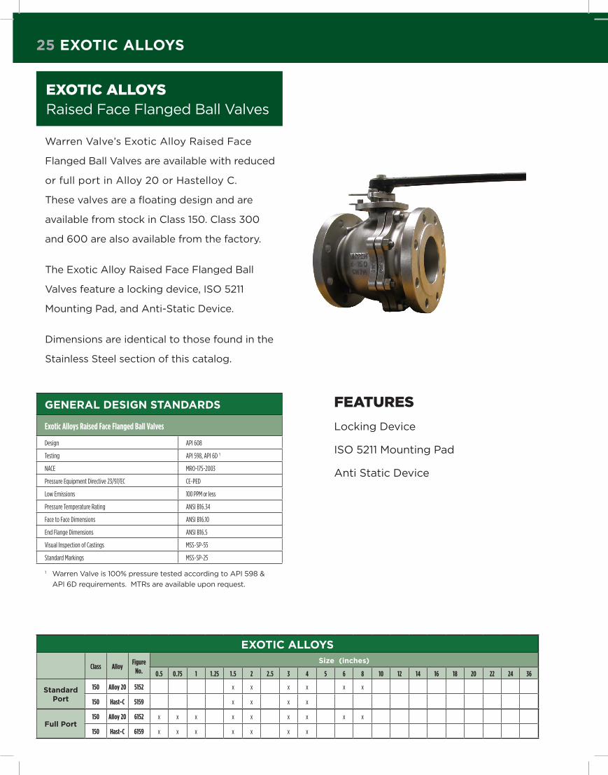
25 exotic alloys
exotiC alloys raised Face Flanged ball Valves
Warren Valve’s Exotic Alloy raised Face
Flanged ball Valves are available with reduced
or full port in Alloy 20 or Hastelloy C.
These valves are a floating design and are
available from stock in Class 150. Class 300
and 600 are also available from the factory.
The Exotic Alloy raised Face Flanged ball
Valves feature a locking device, ISO 5211
Mounting Pad, and Anti-Static Device.
Dimensions are identical to those found in the
Stainless Steel section of this catalog.
geneRal design standaRds
Exotic Alloys Raised Face Flanged Ball Valves
Design API 608
Testing API 598, API 6D 1
NACE MRO-175-2003
Pressure Equipment Directive 23/97/EC CE-PED
Low Emissions 100 PPM or less
Pressure Temperature Rating ANSI B16.34
Face to Face Dimensions ANSI B16.10
End Flange Dimensions ANSI B16.5
Visual Inspection of Castings MSS-SP-55
Standard Markings MSS-SP-25
1 Warren Valve is 100% pressure tested according to API 598 &
API 6D requirements. MTrs are available upon request.
Features
locking Device
ISO 5211 Mounting Pad
Anti Static Device
exotic alloys
Class AlloyFigure
No.
size (inches)
0.5 0.75 1 1.25 1.5 2 2.5 3 4 5 6 8 10 12 14 16 18 20 22 24 36
standard port
150 Alloy 20 5152 x x x x x x
150 Hast-C 5159 x x x x
Full port150 Alloy 20 6152 x x x x x x x x x
150 Hast-C 6159 x x x x x x x

the WaRRen diFFeRence 26
warren valve has been awarded the following certifications for their raised Face Flanged Floating Design ball valves:
ISO 9001:2008
Fire Tested* to API 607 4th Edition,
API 6FA, & bS 6755 Part 2
AbS
CE –PED Certified
GOST Certified
*Applies to Fire Safe Valves
Warren Alloy warrants to the buyer that the products covered by
its invoices will, for the period of one year (1) year from the date
of its invoice, be free of defects in materials and workmanship. All
warranty claims shall be presented by buyer, in writing, within one
(1) year of the invoice date, and buyer shall afford Warren Alloy ac-
cess to and a reasonable opportunity to inspect all allegedly de-
fective products. Warren Alloy will, at is option, repair, replace or
without replacement, render credit for any products which, if prop-
erly stored, handled, used and installed in accordance with the origi-
nal manufacturer’s specifications or designs, industry standards or
other or strict liability in tort, including, but not limited to, claims
for property damage, personal injury, delay or loss of business or
profit, Warren Alloy invoice references to buyer’s specifications or
designs, industry standards or other requirements are for descrip-
tive and/or identification purposes only, and no representation or
warranty shall be created thereby or implied therefrom. Descrip-
tions, illustrations, samples or references to Warren Alloy products
in any catalogue, brochure, price list, circular or similar literature of
Warren Alloy, and any technical assistance or advice provided by
Warren Alloy with respect to those products, shall be for informa-
tional use only and shall neither create new nor modify existing war-
ranties, the exclusive terms of which are stated herein. To the extent
not contrary to public policy, buyer waives any and all rightist may
have against Warren Alloy under the terms of the Magnuson-Moss
Warranty – Federal Trade Commission Improvement Act or the Texas
Deceptive Trade Practices – Consumer Protection Act. Warren Alloy
reserves the right and may; without notice, change or modify the
design and/or construction of any of its products, without liability
or obligation to furnish or install such changes or modifications on
products previously or subsequently sold. thE wArrAntY StAtED
in thiS PArAgrAPhY SUPErSEDES AnD iS ExPrESSlY in liEU
oF AnY AnD All othEr wArrAntiES, ExPrESS or iMPliED,
inClUDing, bUt not liMitED to, thE iMPliED wArrAntiES oF
MErChAntAbilitY AnD FitnESS For A PArtiCUlAr PUrPoSE.
both oF whiCh ArE hErEbY DiSClAiMED with rESPECt to
All ProDUCtS.
The information contained herein is not intended for specific con-
struction or application purposes. Dimensions, specifications, or
materials are subject to change without notice and without liability
or obligation to furnish or install such changes or modifications on
products previously or subsequently sold.
WaRRanty
the WaRRen diFFeRence optionsCHOICES TO CUSTOMIZE YOUR VALVE SOLUTION
every Warren valve is tested and fully checked
for proper operation before shipment.
Our famous triple checking of each outgoing order ensures ship-
ment accuracy, and most of our valves are available for same day
shipment. There is a reason Warren has been the trusted partner
of industrial distributors for fifty years.Warren can also custom manufacture in other material grades. Contact us to discuss your specific requirements.
• venting configurations
• steam jacket inserts
• disc inserts
• special cleaning services
• packing gasket materials
• trim changes
• cryogenics
• bleed holes

Houston7200 Mykawa Road
Houston, TX 77033
p 800.969.5565
F 713.799.1007
Cincinnati9920 Princeton-Glendale Rd.
Cincinnati, OH 45246
p 866.460.9438
F 513.860.3436
Mobile5155 Mobile South Street
Mobile South Business Park #13
Theodore, AL 36582
p 888.653.8031
F 251.653.5498
Edmonton, Canada 172 Turbo Drive
Sherwood Park AB T8H 2J6
T 877.312.7757
F 780.464.0044
Salt Lake City, Utah 1630 South 4650 West
Salt Lake City, UT 84104
p 800.801.2115
F 801.975.9111
Charlotte Area1086 Wilson Business Pkwy.
Fort Mill, SC 29708
p 800.331.3672
F 704.521.8243
Lakeland, Florida 4100 South Frontage Rd.
Building #200
Lakeland, FL 33815
p 877.873.4349
F 863.686.1307
Toronto, Canada 30 Woodslee Avenue
Paris, ON N3L 3V 1
T 888.442.6661
F 519.442.6660
California 11040 Inland Avenue
Mira Loma, CA 91752
p 800.969.9250
F 909.390.0102
Atlanta6040 LaGrange Blvd.
Atlanta, GA 30336
p 800.969.1928
F 404.344.3176
New jersey 266 Ridge Road
Dayton, NJ 08810
p 800.626.9436
F 732.438.0982t 800.231.6680
p 713.672.9416
F 713.672.8549
www.allied-grp.com
Warren Valve is Part of the Allied Group of Companies
ALLIED GROUP


