Page 1
8/12/2019 Ramey_ Wellbore Storage II
http://slidepdf.com/reader/full/ramey-wellbore-storage-ii 1/6
.
An Investigation of Wellbore Storage and Skin Effect in
Finite Difference Treatmentnsteady Liquid Flow: II.
ROBERT A. WATT ENLARGER*
H.J. RAMEY, JR,
MEMBERS AIME
ABSTRACT
An inuest iga tiono/ the ef fect o{ w el lbore s torage
and sk in ef / ect on trans ien t f low w as conducted
us ing a / i n it e-d i ff er en ce solu t ion to the basicL - —...l J ..J / . ——. . ._ 7purLzuL azf [eren lza t equa t ion . The concept 0/ sk in
effect w as genera l ized to include a da rnaged
arrnu la r region ad jacen t to the w el lbore (a compos ite
reservoir ), The numer ica l solu t ions w ere compared
w ith ana ly tica l solu t ions for cases w ith the usua l
steady -s ta te sk in ef fect . It w as found tha t the
solu t ions for a fin i te-capacity sk in ef fect cornp a red
closely w ith ana ly iica i’ .sot ’u iions a i shor i i imes
(w ellbore storage con trolled ) and a t long t imes
a f ter the usua l stra igh t line w as reached . For
in termed ia te t imes, presence of a fin ite-capacity
sk in ef fect caused sign if ican t depar tu res from tbe
in f in itesima l sk in solu t ions. Tw o stra igh t l ines
occurred on the d raw d ow n plot for cases of la rge
rad ius of d amage. The f irst bad a s lope
character ist ic of the f low capacity of the damaged
region; the second stra igh t l ine bad a slope
cbaracterr ’st ic 0 / the f low capacity of the
undamaged region . Resu lts a ;e presen ted both in
tabu la r form and as log-log plots of d imension less
pressures us d imension less t imes. Tbe log-log
plot may be used in a ty pe-curve match ing
p?oce lTg ~Q CZy ra ly ze ShQrf-f j rne (be{cvg ?zClrma
straight line) well- tes t d ata .
INTRODUCTION
Skin effect was defined by van Everdingen 1 and
Hurst’2 as being an impediment to flow that is
caused by an infinitesimally thin damaged region
around the wellbore. The additional pressure drop
through this skin is proportional to the wellbore
flow rate and behaves as though flow through the
skin were steady-state.
Original manuscript received in Society of Petroleum Engineers
office J an. 16, 1969. Revised manuscript of paper SPE 2467
received Sept. 19, 1969. @ Copyright 1970 American I nstitute
of Mining, Metallurgical, and Petroleum Engineers, I nc.
preferences given at end of paper.
“Presently with Scientific Software Corp., E nglewood, Colo.
This paper will be printed in T r a n sa ct ion s vo l um e 249,
which will cover 1970.
MOBIL RESEARCH 8 DEVELOPMENT CORP.
DALLAS, TEX.
STANFORD U.
STANFORD, CALIF.
Wellbore storage is caused by having a moving
liquid level in a wellbore, or by simply having a
volume of compressible fluid stored in the wellbore. 3“,, —.-,,L ---wnen surface fiow rates change abruptiy, weiuzore
storage causes a time lag in formation flow rates
and a corresponding damped pressure response.
A recent study ’1 was made to determine the
combined effects of infinitesimally thin skin and
wellbore storage. Analytical methods were used
along with numerical integration of a Laplace
transformation inversion integral. Tabular and
gra~hical resuits were presented for various cases.
It was recognized during the study that this
representation of skin was oversimplified; that
skin effect should be thought of as a result of
formation damage or improvement to a finite region
adjacent to the wellbore.It was suggested that a skin effect could arise
physically in a number of ways. One simple example
would be to assume that an annular volume
adjacent to the wellbore is reduced uniformly to a
iower permeability than “~re originai ‘-- ‘“--alue. This
would be similar to the composite reservoir
problem. Perhaps a better example would be to
assume that the permeability increases continuously
from a low value at the wellbore to a constant
value in the undamaged reservoir. In either case,
the damaged region would have a finite storage
capacity and would lead to transient behavior
within the skin region.
A negative skin effect could arise from an
increase in permeability within an annular region
adjacent to the wellbore. This might physically
result from acidizing. But it is believed that cases
of more practical importance are those in which
negative skin effects are caused by hydraulic
fracturing:. —-. —.- A high- perrneabiiit~- fracture
communicating with the wellbore gives the
appearance of a negative skin effect.
For the purposes of this study, it was decided
to represent a skin effect, either positive or
negative, as an annular region adj scent to the
wellbore with either decreased or increased
permeability. This then is the composite reservoirproblem wherein a permeability kl exists from the
SEPTEMBER,970 5457 291
Page 2
8/12/2019 Ramey_ Wellbore Storage II
http://slidepdf.com/reader/full/ramey-wellbore-storage-ii 2/6
.
well radius to a radius of the damaged region, rl.
For composite reservoirs. there are an infinite
number of pairs of values, rl and kl, which
correspond to a value of skin effect. s. The main
purpose of this study was to investigate the
behavior of a well during initial transient flow in
the presence of a finite-capacity skin effect with
the presence of wellbore storage. The goal was to
provide information which might be useful in
interpretation of short-time well-test data (either
buildup or drawdown).
The initial-value problem is a special case of a
composite reservoir problem wherein porosity,
viscosity and compressibility are the same for
both damaged and undamaged formation regions,
but with the Permeability changing at the boundary––
of the two regions; the complication of wellbore
storage is also added. The skin effect, .s, does not
appear explicitly in the formulation of the problem,
but may be inferred from the steady-state pressure
drop through the damaged annular region adjacentto the wellbore.
The initial-value problem may be stated as
follows. For the “damaged” or skin region,
a2pl D + J_ap, D3P1D “k —. .
—= —
arD2 ‘D arD ‘1 atD ‘
l~r D<r, D....,..
For the undamaged formation,
a2P2D+ ~ ::2D _ ap2D ;
?lr D2 ‘D D atD
‘l D<rD~ m-”””””
Inner boundary condition,
(1)
(2)
. . . . . . . . . . . . . . . . (3)
PwD(tD) t)p,D(b D
for all tD . . . . (4)
Interface conditions between skin region and
formation,
‘ID= Pm; (r, D, tD) . . . . (5)
aplD k
k—= ~ ; (I-ID, tD) ~ (0
1 arD D
292
Outer boundary condition,
1 im
‘D_’O’P 2D= 0.. . .. .. . 7
And the initial condition is,
‘1~ (rD}O)=p2D(r D,0) = O . . . . (~)
The dimensionless variables have usual definitions,
‘D=r/rw’ ””””””””””. (9)
kt lo‘D=—’”””-”””””” “
q~c rw
p~D(r DJtD) = & (pi-p~, t) ;
r ~r < r, . . . . . . . . . . .(11)w
‘2D(r D>tD) = & (Pi-pr, t) ;
‘1<r~ ~, . . . . . . . . . . (12)
PwD tD) = pi-pw) “ “ “ ’13)
t=c (14)
21-rhqcr z’””””””””””w
where C represents the fluid storage capacity in
the wellbore, cc/atm.
The equivalent steady-state skin effect, s, can
be expressed as a hrnction of k, kl, r l and rw.
That is,
s= ~- l l n ~
i w
= (~ - 1) lnr, D”. .. (15)
Thus, it is possible to select appropriate values
of ~1~ and (kIkl) to provide a specific value ofl-- -1.:- -I L--- T1-- .-l-.: .––l-– ~.. —.-– .L -L1lC SYK1ll CI ICC-L. J ne relaclonsnip Derween tne skin
effect and the pressure drop attributable to the
skin is
2rrkhs = ~@ Skin . . . . . .. (16)
Strictly speaking, the above problem may be
solved to provide the pressure at any time andradial location within either region. But since the
SOCIETY OF PETROLEUM ENGINEERS J OURNAL
Page 3
8/12/2019 Ramey_ Wellbore Storage II
http://slidepdf.com/reader/full/ramey-wellbore-storage-ii 3/6
main obiective was information for well-testTABLE 1- VALUES OF rlD AND (kI/k) USED FOR VARIOUS
SKIN EFFECTSnalysis, only pressures at the well were sought.
All results reported in the study are for
dimensionless pressures at the well which are
denoted as pwD (tf)).
Although the subject problem may be handled
analytically with ease, the analytical result would
require numerical integration to provide finaltabulations of the dimensionless variables.
Fortunately, a finite-difference computer program
was available that could readily handle the
problem. The program was a one-dimensional
radial model prepared to solve real gas flow with
damage and wellbore storage. The details of this
program have been described previously. s, ~
Solutions for liquid flow were obtained by employing
constant-fluid physical properties. The
finite-difference solution represented a finite-radius
reservoir. But the reservoir radius selected was
large enough so that pressure a t the ou ter boundary
was not affected for producing times of tD x 108.
A check of the outer boundary pressure was madefor each run. In addition, all solutions were found
to agree closely with the infinite-reservoir
analytical solution for the longest producing times
run. Since solutions to the diffusivity equation
were obtained in terms of pressure, the usual
assumption of small pressure gradients throughout
the flow system was made.
Give n a value of equivalent skin effect,
corresponding values of ?lD and (k I/k) were used
in the model. Values of rlD = 1, 10, 100 and 1,000
were used to give a range of conditions. The case
of rlD = 1 is equivalent to the van Everdingen-Hurst
infinitesimally thin damaged region. When no
wellbore storage is present, the solution to thiscase can be obtained by adding the skin effect to
the s = O solution. When wellbore storage is
present, the solutions to this case are equivalent
to those solutions given by Agarwal et a l, 4
A negative skin effect in a composite reservoir
implies that the region around the wellbore has
improved permeability, k.l > k. It should be noted
that for a given radius of permeability improvement,
rlD, there is an upper iimit to the magnitude of
negative skin effect. This limit is reached as the
p 5 5 f 1 m ~=bi i i ~~ -GL2 2 3 d~~ le ~ , e i i ~e r e ~p p ~~~~~~ ~
Skin-Zone
Radius, rlD (kI/k) for Skin Effects, s, of
–5 +5 +20
10 0.3153 0.1032
100 0.4794 0.1872
1,000 3.6209 0.5801 0.2567
TABLE P — p,”” (?.) VS tD FOR * O
10 100 1,000 10,000 100,000k
;51. 104
2 X 1 0’
5. 10’I . 102
2. 10’
5. 1021 x 10’
2. 103:: ;;:
2 lo~5. 1041. 10,
2. 1055. lo~I . 1062. 106
5. 1061. 107
2. 1075. 1071, 10,
0.0000099822O.oow 199640.WOC1499100.000099818
0.030199630.00049’3040.00099798
0.00199560.C+2498660.0099663
0.0199070.049592
0.098654
0.195340475040.91122
0.779351.00461.3493
16411
1.9513
2.38162.7164
0.090324
0.172340.W88
0.677091.10461,82072.28892.8794
0 0 0 9 s7 9 50019659
0048558
0,0955
0.185990435140,79441
0000997190.00199340.0049713
0.W99282
0.019821
0.0492060.097432
0.19146
0.457220.855751,5237
2,86684.OIXI
4.915J25.66176.0823646156,93827 i 91 97.6412
3.05s0
3,50883.8534
419844.654950008
5,3465580336.15016.49596.95261,29937,64518.10248.44368.7947
9.25179.5982
0.019880
0.0496670.098243
0.193990.668520.88987
1.6X293.19044.6539586196,77147,21697.6042
3,43223.81294 1 76 74.s4534,9958
5.34235.80216.14?56 4 9%
6.95257.29937.6451
1.6865
3.43515.18696.7373
8.10248.44348.7947
8.10228.44848,7966
9.2517
9,5982
8.10278.44768,7942
9.25159.598I
8.08568.4398
879029.2498
9.5972
7,27668.3504
8.747?
9.23259.5883
9.2517
9.5902
.F, ,e.plm p,ec, ,,m, WO, token f,m ,Im c.mptie, OU p,,, b“, doe, no, ,,wIY rho he
,.lti,.n h-. lht $ dew.. d OCCWmy.
TABLE 3 — p,, [,,,) VS ,n FOR s s, r ,,, 1,000
~0.334740,41377
0.52578
0.61522
0,70689
0.820440.9249 I1.0199
1.14s31.2412
1.3247
1,4623
1.5584
1 65S9
1.7803
1.8811
2.0053
2.2353
2.46692.7401
3.1472
3,4754
3.8125
4.26414.6084
J. @-
1
1
~0.0803730.144670.=5230.43189
0,50913
0.777060,39669I 0049
1,1392
i ,2371
1.3343
1,4625
1.5380
1.6537
1.7802
).88 10
2.0052
2.23572.4669
2.7402
3.1472
3.4754
3.8125
4,26414.6088
~ 1,000 10,000 100,000
0.00000998210.000019964
0.000049908
0,0000998120.0W19961
0.000498920.000997S40,0019962
0.0097524
0.019266
0.046705
0.0895710.16676
0.350690.55918
0.79531
0.000995880.0019893
0.0049575
0.0098715
0.019591
0.0430190.093311
0.17733
51. 10,
2. 10
5’. 101 102
2> 1025. 102
I x 1032. 103
5. 1031, lo,
2, 104
5> 10*1. 102
2. 105
0.0099141
0.0197230.063609
0.0951620.18322. . . . . .“ .4 ’ .
0.708571.0970
1.5772
1.0541
1.2002
1.3163
i.45431.5540
1.6s16
1.7793
0.388860.64782
0.96432
i.32741.5021
1.62771.7697
1.8805
2.0049
2 2 3 SS
2.66682.7401
3 1 47 1
3.4753
3.81254,26414.6088
1.8751
2.0012
2.2332
2.46S2
2.7391
3.1466
3.47503.8123
0.752451.2053
1.8477
2.25412.6154
3.086)
3.4608
5. lo%
I . lo~2> 106
5. 104
1. 10?2 k 10,
5. 1071 x 108
3.7934
4,255s4.6041
4.26404,6087
4.26334.6083
Infinity.
limiting
s =
Table
Ftom Eq. 15, it can be seen- ‘that the
negative skin effect (as k l + CO) isTABLE 4—OD(,DI VSIDFORS– +5, r,D - 1
A-
;51. 10
2> 108
5, 10’
1, 10’
2, 10’
5> 10’I. 103
2. 1035, 103
I, 104
2, 1045, 104
1, 105
2, 1055> lo,
I Y 10*2. 106
5, m
1, 10,
2 x lo,
5, lo?
1, 108
10 100 1,000 10,000
.— —
100,000
0.098841 0.0099724o.o199m
0.049695
0.0990W0.19650
0.48083
0.939901.7463
3.68265.7702
0.000998120.0019961
0.00498890.0099739
0.019933
0.0497240.099108
0.19692
0.000099818 0.00000998040.000 1W63 0,000019956
o.ooc14wr17 0.000049899
0,@32W811 0.0C029930Q
0.0019961
“nrl D.”” ”””” ””. ”( 17)
5,7705
5 9 %5 5
63405
6.6323
6.9425
7.37287.7076
8,0471
8. 2018.8446
9.18969.6660
9.992.2
10.338
0.794
11.141
11.487
11.944
12.291
12.636 3.094
13.444
13.786
14.243
14.389
0.196030.47808
0.923071.7112
3.5’2395.36577.036 I
& 2S568.74169.1299
%62609,9818
10,33210.792
0.00019962
0.00049906
0.000998120,w1W61
0.CH349S9S.
0.0099760
0.0199410.0497700.099279
0.00698920.0099730
0.019923
0.0497490,099200.197a
0,48521
0.945721,8005
3.9259
1 shows the values of (k I/k), which
correspond to the various va lues of r lD and s in
the study. The first two entries for s = –5 are
blank because this negative skin effect is not
obtainable for rlf) = 10 or 100, according to fZq. 15.
RESULTS
Finite-difference solutions were generated for
a totai of 60 cases. ~-~1-- ‘-l -L-- .. ..h 1 1 -;.?- ~~~1i3U1C> L LLuuu~ll LL ~AVL
results of these computer runs . Each table gives
sEPTEMBER, 1970
0.48326
0.9s751,7767
3,8169
6.1196
8.5@3010,29611.002
7,80119.3341
9,871410.39110.772
0, 197s5
0.48672
0,951%1,8204
4.0193
6.6834
9,727012.46713.256
11.140
11.487
11,944
12,290
12.626 3,094
13.440
13.786
14,243
14,589
11.130
1 ,481
11,941
12.i89
6,4242
9.1463
11.41
12.131
12.365
13.066
13.426
13.779
1&‘m
13.708
14,213..—.14.ar44.568
293
Page 4
8/12/2019 Ramey_ Wellbore Storage II
http://slidepdf.com/reader/full/ramey-wellbore-storage-ii 4/6
.
TABLE 5 —pD (fD) VS t D FOR S= +S, rtD= 10the results for given values of s and r~D. In each
table the various wellbore storage cases are listed,
ranging from 77= O to ZT= 100,000.
Only the solutions at selected values of tD are
shown. Smaller time steps were taken between the
printed results to reduce the time truncation error.
A total of 816 time steps were taken for each case.
The cases of infinitesimally thin skin (r~D = 1)
were compared to the ‘‘analytical” solutions of
Ref. 4. Solutions in Ref. 4 were obtained by the
numerical integration of an inversion integral. The
agreement h =rv~~~ & ~~~ ~~~ca .,-. hi.:,..-. e-W. u ..””= al-id
finite-difference solutions was excellent. The
maximum differences between the two were about
~=~ 10 100 I ,w a 10,COOA.. . ——— 100,0001 1.5404 0.094963 0.0099317 0.00299772 0.WW99817
1
0.0WO09W23
2.0907 0,18566 0.019814 0.0019949 0. WO19963
5
0,00@319965
2.9418 o.439a4 0,0492S9 0,004984S 0,00049905
1,103
o.omo4991 1
3.7167 0.82430 0.097818 0.0099619 0. WW9802 0,000399821
2X1O’ 4.5849 1.4903 0.19336 0,0199W O.w 1W58 0.0C019964
Sxlof
1 x 10²
2 x 102
s x 102
1 x 1032 x 103
5 x 10³
1 x 10⁴
2 x 10⁴
s,842a
6.813s
7,6336
8.37~
0.78789.1627
9.6336
9,9m.9
10,33s
2.’W87
4,5972
6.3326
8.0045
8.66179.1087
9.6147
9,9764
10,320
0,47009
0,906811.6942
3.3776
5.66Il 17,6W7
9.3(E.9
9,8637
10,278
0.04 3608
0.098820
0,196250.68142
O.93XI61.7698
3,8060
6.1034
8.6872
0.0049%8 1
0.0099721
0.019934
0.0497%
0.0991630,19719
0.483W
0,94S31
0,W0499Q8
0.000996120.0019961
0,0069893
0.00997560.019940
0.04W67
0.099275
0.19754.7998
s x 1041 x lo~
2 x 10>5 x 10⁵
I x . lo ~
2 x 10⁶
:: ;;;
2 x 10⁷
5 x 10⁷
1 x 10⁸
10.793
11,141
11,487
11,946
12290
12.626
13,094
13.46013.786
14.243
10,791
11,140
11,486
11,943
12.290
12,6%
13.094
13.660
13.706
14.243
10,771
11.122
11,431
11,941
12.~9
1Z626
13.093
13.439
13.736
14.243
10.392
11.002
11.423
11,919
12.278
12.630
13.091
13,4=
13,785
14.243
3.9245
6,4224
9,1448
11.440
12.131
12.565
13.046
)3.426
13.779
14.24U
14.388
0.686700.95134
1.8X33
4,0191
6.6832
9.7268
12.467
13.236
I 3.708
14.213
14.3744.5%9 14.389 14.389
TABLE 9 —pD(tD) M ,D FoR ,=+N, rD= 10TABLE 6 — ,,D – Im
10,000.—
0,0W0998160.00019963
0.W049903
0.W0997960,C419956
0.00498700.0099684
F= 0 10-—
0.093595
0.18161
0,42415
0.779731.3s75
2,5813
3.74s3
4,9155
6,26637.1110
7.9057
100 1,000.—
loo mo ?-0 10
0=5
0. 192*
0.44780
0,905601.7219
3.8s606.7178
10.915
17.755
10 0
0.009958 I
0.019890
0.049562
0.098823
0.19658
0.485260.936421,85s8
4,32097,8278
13,033
20.652
24,032
2s.112
25.706
26.08526.466
I ,wo
0.00099798
0.m19957
0.W249878
0.0099722
0.019933
0.0497710,099372
0,198170.49182
10,W3O
0.LWO09982U
0,Wi719964
0.W449’W8
0,W0998120.G121996’l
0,W498970.L?Q99777
0.019950
0.049837
0,099564
10 0mo-o.omm99823
0.WW19965
0.00W49911
0,mm9m220.00019964
0.000499 IO0,0W99818
0.0019962
0.00499040.0099796
3.1149
4.1034.2271
1,6117
2.2328
2.7824
0,00991680.019771
0.049064
0,000997570,0019965
0,0049025
0.00995S50.019879
0,0495020.0964%
0.19.9220.475s3
0.0LxXH299823
0.WQ1319965
0.00W49911
0,0000998210,W21W64
0.WQ$9’W70.00099809
0.001995.0
0.W49887
0.0099726
0.01W34
0.049742
o.099m7
0. 1972a
0.6862Q
0.95029
2
:1,10
2x10’
5,101
I , 102
2 h 10’5X 1021 x 103
2 x 103s x 103
51.10
2X1O’
s. 10’I x 102
2x 10²
:: ;::
2. 103
; H m:
2 x 10⁴
5 x 1041 x 10,
2 x 105
s x 1051 x 106
2 x 1065 x 106
I h 107
2 x lo~
5. ]o~
1. 10,
5,9241
7.7232
9.8762
13.21216.034
18.994
0.0971980,19135
0.660d7
0.873861.5999
3,23804.9438
3.sass
4.2446
4.925S
5.6231
6.%017.2757
7,9935
0.019917
0.049667
0.098965
0.196590.68260
0.939151,78S7
3,8917
6.2749
22.236
23.472
24.040
24.576
24.945
25.241
25.764
26.11326,440
26.9)7
27.264
27.610
20.0+7
28.413
28.759
29.21629.s43
21.884
23,726
24.514
24.917
2s.287
25,759
26.110
26.45326.916
27.264
27.610
28,067
28.413
23.759
29.216
29.563
0.972811.9068
4,4793
s3.134213,W7
21.386
25,165
26.266
0.917241.7203
2.650 I
5.8329
8, 18Q8
10.257
10.959
11.607
0.198700.49263
0,97722
1.9155
4.5156
8.226213,849
0.019955
0.049856
0.0996090. PW81
0.4940s
0.978571,91994:s372
8.305214.0S4
22,932
37.170
28s3429.151
29.532
6.60898,4575
9.396110,07S
10.706
11.10011.4s7
8.92929,6076
10.660
10.733
11.112
11.473
i L938
12.288
12.635
13.093
8.90139.sa94
10.152
10,730
11.111
11.473. . .
l.Y.M
12.288
12.635
13,093
13.439
I x 104
2 x 10⁴
M:
2 x lo~
5X 10.
I. 10e
2x. 1065.106
1.w7
2. 107
5. 1071 x 108
9.0989., . . ., l..’.
12.127
12,564
13.065
13,425
13,779
14.240
14.s88
1,8182~,o;a
6.677)9,7210
12.464
13.2M
13,708
14.21316.574
26.911
27,Z1
27.608
28.06728.413
28.75929.216
29,%3
26.r537
27,23S
27,395
23.061
Z.41O
~.758
29.21629.563
22.2?5
26,183
27.601
28,m4
B.363
28.745
29.21029.560
--,I I., SJ
12.227
.....,,.,,.12,275
12,6%
13,090
13.4%
13.785
14.243
14.529
12.634
13.093
13.439
13.786
14.24314.369
13,439
13,786 13.786
14.243 14.243
14,589 14.389
TABLE 7 — ,eD(tD) vs ,0 FOR s= +5, ,,D= 1,000
F= o 10 100 I 000 lo,om 100,030—— —
TABLE 10 — m (*D) VS tD FOR ,=+22, rm = 106
75.0
2.16372.8709
4,1026
S.2671
6.6105
8.6171
10.265
11.989
14.261
16.153
17.982
20.410
22.246
23.939
25,605
2S.981
26.401
X , 895
27.2s3
27.604
~.06S
28.412
28.759
29.216
29.563
10 10 0 ),om-— —
lo , mo
0.000099819O.OOQ19963
0.00049906
0.00099808
0.0019960
0.&2498W
lW,C.20
0.00W0998230,000019+6S
0.0W”24W11
0.000099822
0.0W19964
0,0004W09
~
12
51.10,
2> 10,
5.10
1.102
2.10,
5x10²
I. 103
2. 1035. 103lx 104
2. 104
5. 104
lx 101
2x lo~
5x lo~1X 10⁶
2X 10⁶
5x10⁶
lxlo~
2.107
5X10⁷lx lo~
0.0a66o. 179s50.415780.756181.3068
2.2S74
3.2684
4.3105
5.2678
6,C418
6.7088
7,s293
8.1330
8.74039.5321
10.131
10.7~
11,309
12,03E
12,526
13.054
13,421
13.77714.239
14.W
1.092S
1.42391,9643
2.4324
2.9415
3.64104,2a3
4.8076
5.5$40
6.1762
6.7700
7,53S2
8. 1S23
8,74809.5354
10,133
10,7B
11.. 0912.058
12,S26
13.054
13.421
13.777
14.23914.5S8
0.009W86
0,0197470.0489550.096850
0,19022
0.4S507
0,8%621.5474
3.035$
4.4972
5,8823
7.2335
0.00099768
0.00199430.0049814
0,00995180.019867
0.0496410.098245
0, 194=
0.47174
0.000099815
0,CJ20199620.00049902
0.000997920.00199S5
0.0449864
0,0399663
0.019910
0,04%27
0.WIOW199823
0.0000199650.000049911
0, W2WW200.00019964
[email protected]
O,W 19959o.m49a83
0,w99721
0.019923
0.049712
0.099097
0.19698
0.6S416
0.942761.7989
3,96826.3643
9.3482
12,348
13.325
13.696
14.209
14.572
0 ,096322 0 .W996610.18919 0.019856
0,45SW 0.049428
0,86832 0.098379
.6145 0.19517
3.42S0 0.47870
0.002997860.0019954
0,0049864
0.0099676
0,019919
0,049701
25
1X1OI
2X1095X 104
1 x 10²
2 x 102
s x 102I. 103
2 x 103
s x 103
1 x lo~2.104
5 x 1041 x 10s
2 x lo~
5 x lo~1 x 10*
2 x loo
s x lo~
1 x 10⁷
2 x lo~
5. 107
lXICF
S.6514
8,4988
12.491
15,153
17.453
30.18022.124
23.88325,393
23,977
26,400
26,894
27.253
27.604
2U.W.528,412
i9.759
29.216
39.563
0.93297
1,7865
4.0154
6,9544
11,035
16.980m.62u
23,243
2s.260
25,960
0.099137
0.19737
0,68775
0.95960
1,8629
4.3123
7,7255
12.797
m,6m
24.672
0.0099754
0.019942
0.049796
0.099423
0.19824
0.49162
0.97146
1,9003
4,4707
0,0W99816
0.0019962
0. W49900
0.0099782
0.019950
o.049a3s
0.099530
0.19865
0.49352
0.904321,6778
3.66e6
5.3747
7.2963
9.0704
9,9275
10.638
1}.669
12.02+
0.0%8 18
0.19606
0.479730.92903
1.7517
3.75W
6,0415
8.52-?310,867
11.a22
7.9929
8.6671
9.S212
10.I15
10.72Q
11.506
12.0%
12,526
13.053
8.1S11
13.72U
22.152
26.12a
37.394
=.002
‘m.282
2s.744
J2.97738
1,9174
4,5311
8.2945
14.039
22,918
27.164
28,533
26.345
26.889
27.2%
27.603
2s.064
29,412
22.7s9
26.13a
26.831
27.223
27.3W
29.059
Z.609
26.79
12.518
13.051
12.435
13.023
13.426
13.76914,236
14.586
13.42013.777
14.23914.588
13.41913.776
14.239
14.SS729.216
29.563
29.216
29.%2
29.210
29.560
29.1s1
23.531
TABLE 8 — p= (,Dl VS tD FOR s= +%, rm= 1TABLE 11 —p.D (tDl VS ,D FOR ‘=+X( rm= l,OW
?= 10 100A___ ———
,000 lo,mo lW,WO F= o 10 100 I,W2 Io,ow 100,WO—. —— _
1 20,744 0,099558 0. W99796 0.00399819 0.00W998152
0.GfKI0099765
20.%9 0.19865 0.019954 0.0019963 0.00019961
s 21.3140.000419942
0.49306 0,049830 0,0049904 0.0W4990S 0.00W369870
lxlo~ 21,606 0,97667 0,099583 0,0099797 0, W099808 0.00W1997%
2XF2* 21,916 1,9047 0.19870 0,01W5S 0,0019962 0.00019954
5xml~ 22,366 4.4528 0.49334 12.049853 0, W49W4 O.W049899
1,7887
2,2707
3,3%3
4,2706
5.2044
6.8217
8.05109.3265
I 1.036
12.384I3.720
15.493
16.83
18.184
0.0955S4
0.18705
0,64633
0.84322
1.5429
0,0099379
0,019832
0.069337
0.098063
0.19415
0,47387
0,917iU1,7353
3.79m
6,33079.5684
13.687
16.WO17,770
}9.796
0J30QW778
o.m~995~
12.oo49a53
0.W99644
0.0 IW08
0,049649
0.098961
0, 1%77
0 ,0 w 0 w 8 ) q
0.0001W63
o.om4990s
0.0009W05
0,001W59
0.0049345
0,00997%
0.019935
0,049763
0.000WW823
o.omowms
7MOO0499 t1
0.0CK099822
0.00019964
o.om49909
0.00099314
0.00199620.0049896
o.m9977 I
0.019946
3,1747
5.0234
7,216110.023
11.83813.431
15.356
16.771
18.147
i x 102
2 x 10²
:;}:
2 x 10³
5 x lo~
I x 104
2 x lob
5X10⁴
22,68 I
23.021
23,474
23.818
24.163
24.6m
24,966
25,311
25.768
8.W7413.163
20.273
23.1 IO
24.mo
24,565
24,939
25,2W
2S,763
0.97s I
1.9086
4.4757
8.0899
13.608
X.%624,149
2s, I33
2S.711
0.099593
0.198740.49360
0.976691.9127
4.4979
8.165513.632
21.621
0,0099798
0.01 W55
0.049856
0.099604
0.19879
0.4928s
0.977671.9164
0.W099807
0.0019962
0.W49904
0.00W7W
0.0 199s
0.0498390.099614
0.19882
0.68462
0.94352
1,8255
4.1312
7.176111.2M
o.owm80.19783
0.6893s
0.963201.8713
4.3% I
7,721512.6V19,995
0.049812
0.099665
0.19834
0,49181
0,971521,8984
4,4514
8,092513.633
4.5176 0,49408 19.962
21,313
22.660
24.424
25.76S
26.W3
27.869
za.330
2U.721
29.202
19.947
21.205
22.b55
24.437
25,764
26.W8
27,869
2a.320
23.72129.m2
29,5s
17.031
a. 10022.KZ
24.231
2S.664
26.867
27,Mo
2%.336
28.719
29.X7139.555
1 x 1032 x 10s
s x 105I x 106
2 x 10⁶
5 x 1061 x lo,
2 x 10⁷
5 x 1071 x 108
26,115
26,6$1
26,917
27.264
27.610
m ,J67
=.413
28.759
29,216
29,563
26.112
26.439
26.91727,2S4
27,61028.067
28.413
m.759
29.216
29.563
2b.087
26.44726.912
27.26}
27.608
28067
~.413
28.759
29,216
29.563
25.178
36.269%.89
27.235
w .596
23.061
28.410
23.73029.216
m’,363
8.2396
13,854
22.279
26.105
27,601
23,m4
B,ra3
m.745
29.21039.s0
0,97862
1.92u3
4.5374
8.2055
14.055
22.933
27,171
23.534
39.15129.532
21.227
22.615
24.419
25.75S
24.904
2T,868
23,330
23.72129.202
29.53s
24.059
26.32627.761
ZU.293
2U.705
29.19s29,553
22.281
26.866
33,43
29. 2429,524?.556
294
Page 5
8/12/2019 Ramey_ Wellbore Storage II
http://slidepdf.com/reader/full/ramey-wellbore-storage-ii 5/6
‘“~
4tt4LyT C&L —
F,N, TE OIFFERENCE -
I
tc
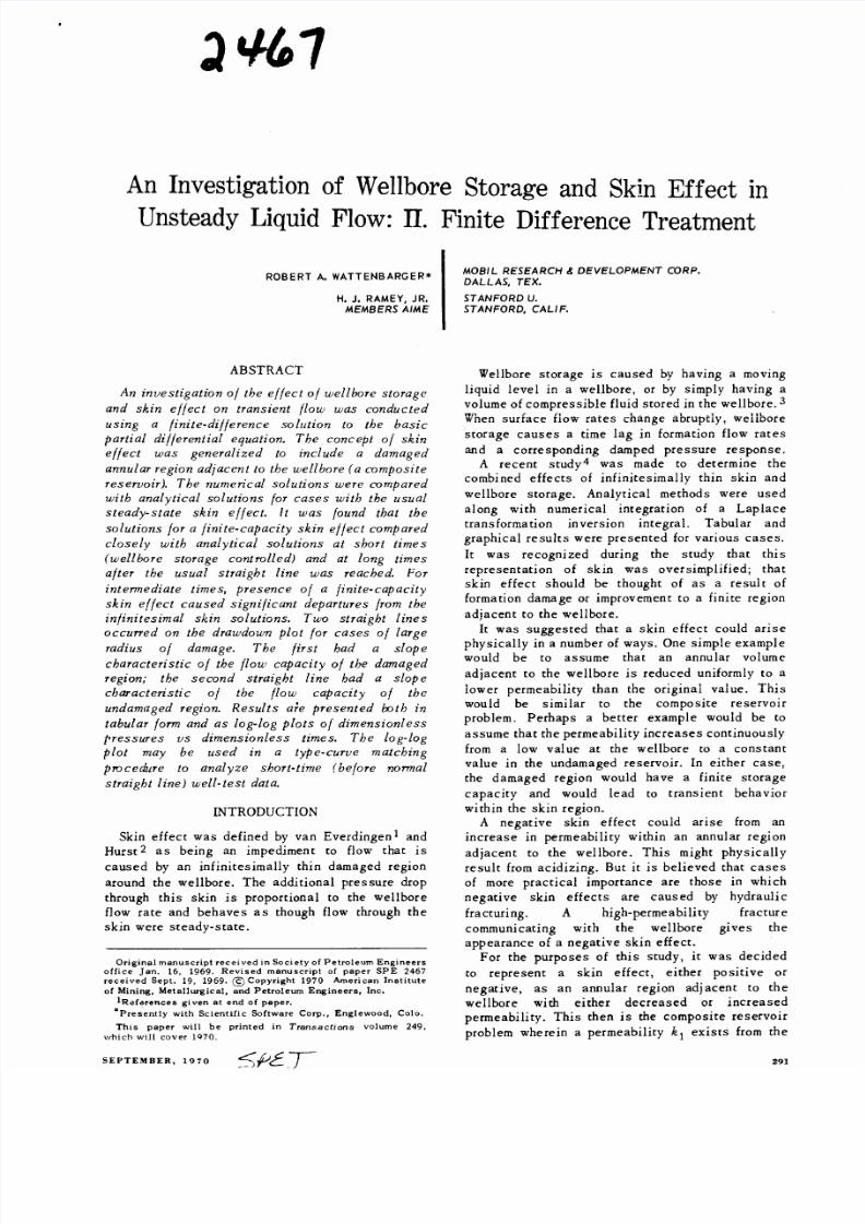
FIG. 1 — /J L) ( D) VS tD FOR ANALYTICAL AND
F INI TE -DI FF ER ENCE S OLUTIONS S= O .
0 .5 percent, with the analytical solutions being
higher than the finite-difference solutions. This
maximum difference occurred for the larger values
of ? at the transition between the wellbore
storage-controlled period and the period in which
wellbore storage was not importanr. On Q log-iog
plot of p~(t~) vs tD this is the region of greatest
curvature. At other points on the curve the solutions
are almost identical.
Fig. 1 shows a comparison of the aiiaiyti~ai
solutions from Ref. 4 (solid lines) and
finite-difference solutions (points). The differences
between the two are not noticeable on a graph. All
of the curves in Fig. 1 are for no skin effect, s = O.
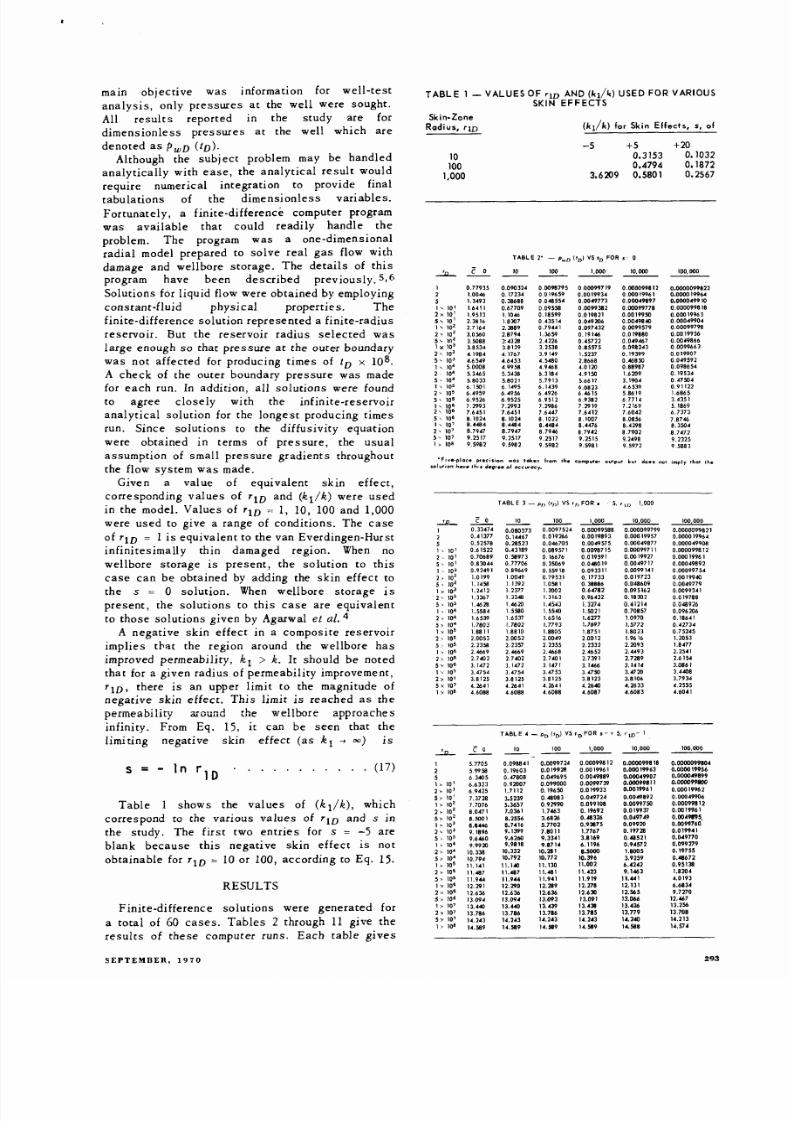
Fig. 2 presents results for skin effects of –5, O
and +20. The skin effect of +5 was not plotted to
make Fig. 2 more readable. Dimensionless pressures:~,~a ~ii e
nlnrfed with skin.v---- effect,
d imension less radius of the damaged zone, and the
dimensionless wellbore storage constant as
parameters. The results for the skin effect of -5
are only for a dimensionless ‘ ‘damaged” zone
radius of 1,000. It was impossible to achieve a
negative skin effect as large as -5 with ~~D values
less than 150. Thus, the data for a skin effect of
+20 on Fig. 2 are best for studying the effect of
the radius of the damaged region upon short- time
well-test data. Results for a skin effect of +5 were
simiiar.
DISCUSSION
AS shown in Fig. 2, by comparison of results
for different rl~ values, representation of a skin
effect as an annuiar region of aitered permeabilityl-=, -l @cart .> ..* sigcificarrt chan~es in the early
pressure-time history, with or without wellbore
storage. (All lines on Fig. 2 for rl~ = 1 represent
infinitesimally thin skin cases, or previous
analytical cases. ) The lines for the finite-radius,
damaged regions fall successively below the
infinitesimally thin skin case, but finally join the
infinitesimally thin skin case at times which
increase as the damage radius squared, as would
be expected. If there is significant wellbore
storage, a separation is noticed within the
transition region from storage control to outer
formation control, as damaged-zone radius increases.
The separation diminishes with increasing weiibore
storage constant and is essentially negligible for
storage constant of 100,000. This results because
the finite-storage constant cases must join the
zero storage case. “--:.-.:- -. .helnus P~. i?ViOiiS LIIKlla LUl L1lC
duration of the wellbore storage effect a requires
some modification. If the damaged-zone radius is
great, transients caused by the large volume of the
damaged region may last longer than those caused
by weHbore storage. In extreme cases, this could
result in an early period caused by wellbore storage,
followed by two straight Iines on a conventional
~emli]og ~e]].te~~ P]QC — the first having a sloPe
indicative of fie permeability of the damaged region;
the second having the correct slope indicative of
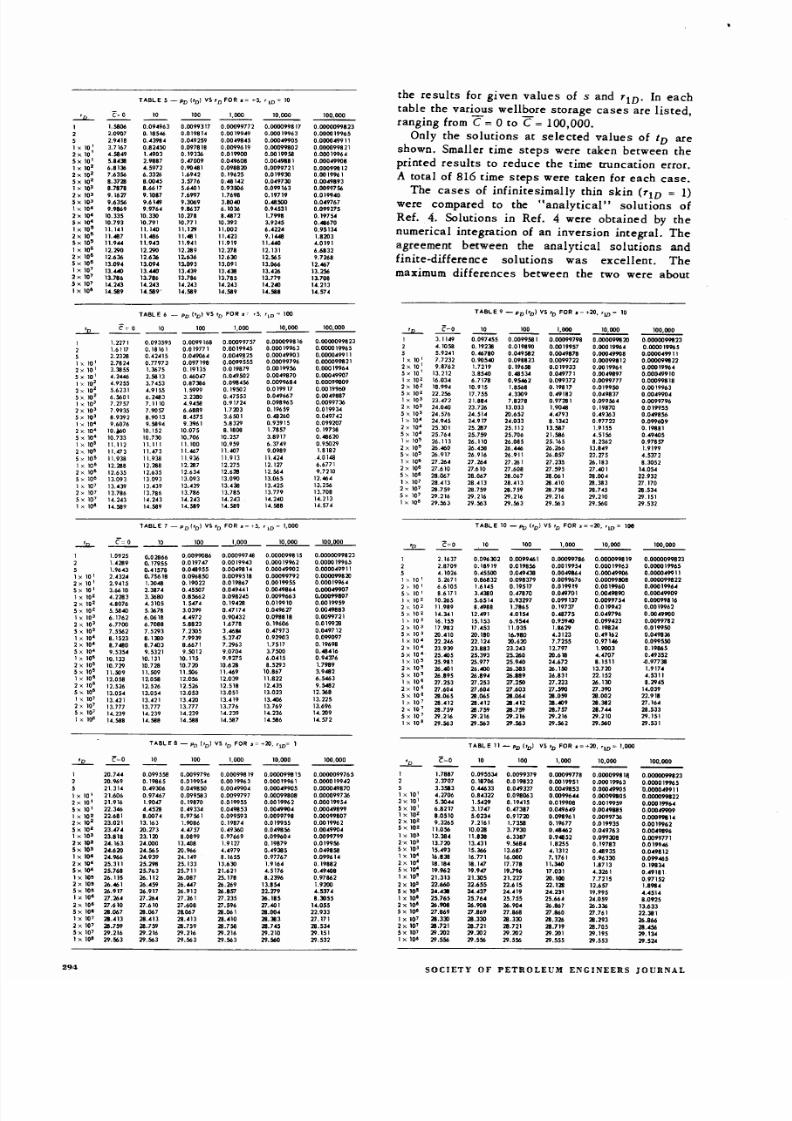
the undamaged formation. This is shown on Fig. 3.
Fig. 3 presents results in a conventional semilog
plot of the pressure-time data for a skin effect of
+5, a storage constant of 1,000, and two different
damaged-zone radll: ~lD of 1 and 1,000. pressure. .
data to a time of about 2.5 x 10³ are almost
S*2O
-C. O rlo=i,
/ il Kr
1. .
I// 1 1 1,“
I 10 102,. 3
1 0104 105
,06 107
FIG. 2 — SHORT-TIME SOLUTIONS WITH WELLBORE STORAGE AND FORMATION DAh lAGE
sEP’YI:MIII:I{. lv70 295
Page 6
8/12/2019 Ramey_ Wellbore Storage II
http://slidepdf.com/reader/full/ramey-wellbore-storage-ii 6/6
cQ.rn.pje.@7 ,-L-,m;., c.cl by : ~,e “ alll..-..a-..”,.=..”,..l., c.. &u WL. .”” c
-’u’’=~~
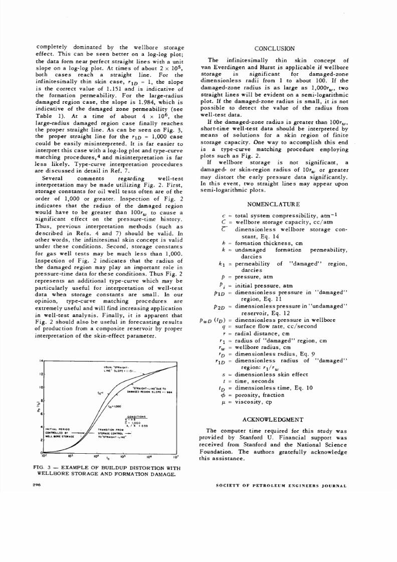
effect. This can be seen better on a log-log plot;
the data form near perfect straight lines with a unit
slope on a log-log plot. At times of about 2 x 10⁵,
both cases reach a straight line. For the
infinitesimally thin skin case, 71D = 1 the slope
is the correct value of 1.151 and is indicative of
the formation permeability. For the large-radius
damaged region case, the slope is 1.984, which is
indicative of the damaged zone permeability (see
Table 1). At a time of about 4 x 10⁶, the
large-radius damaged region case finally reaches
the proper straight Iine. As can be seen on Fig. 3,
the proper straight line for the TID = 1,000 case
could be easily misinterpreted. It is far easier to
interpret this case with a Iog-log plot and type-curve
matching procedures, q and misinterpretation is far
less likely. Type-curve interpretation procedures
are discussed in detail in Ref. 7.
Several comments regarding well-test
interpretation may be made utilizing Fig. 2. First,storage constants for oil well tests often are of the
order of 1,000 or Qreater, nsrwction CIf Fig. ~.– —.-. =-------
indicates that the radius of the damaged region
would have to be greater ban 100rw to cause a
significant effect on the pressure-time history.
Thus, previous interpretation methods (such as
described in Refs. 4 and 7) should be valid. In
other words, the infinitesimal skin concept is valid
under these conditions. Second, storage constants
for gas well tests may be much less than 1,000.
Inspection of Fig. 2 indicates that the radius of
the damaged region may play an important role in
pressure-time data for these conditions. Thus Fig. 2
represents an additional type-curve which may beparticularly useful for interpretation of well-test
data when storage constants are small. In our
opinion, type-curve matching procedures are
extremely useful and will find increasing application
in well-test analysis, Finally, it is apparent that
Fig. 2 should also be useful in forecasting results
of production from a composite reservoir by proper
interpretation of the skin-effect parameter.
:.
:6 .
c0N01710N5
5.+5
T . ,000
4kl/k .059
I NI TI AL P fR ,0 0 TR , W3,,,0N mow
5TORACE CONTROL 4 ’
WELL BORE STWAGE ) T O%l RA , G ” T . L , N E.
2 -
0102 K)3 104
to105 ,06 I07
FIG. 3 — EXAMPLE OF BUILDUP DISTORTION WITHWELLBORE STORAGE AND F ORMATION DAMAGE .
------ .rm. n.,
~UN~L U>lUN
The infinitesimally thin skin concept of
van Everdingen and Hurst is applicable if wellbore
storage is significant for damaged-zone
dimensionless radii from 1 to about 100. If the
damaged-zone radius is as large as l, OOOrw, two
straight lines will be evident on a semi-logarithmic
plot. If the damaged-zone radius is small, it is not
possible to detect the value of the radius from
well-test data.
If the damaged-zone radius is greater than 100rw,
short-time well-test data should be interpreted by
means of solutions for a skin region of finite
storage capacity. One way to accomplish this end
is a type-curve matching procedure employing
plots such as Fig. 2.
If wellbore storage is not significant, a
damaged- or skin-region radius of IOYW or greater
may distort the early pressure data significantly.
In this event, two straight lines may appear upon
semi-logarithmic plots.
c=
c.
c-
l?=
k =
k l =
p=
i
plD =
P2LJ=
~w D t D) =
q=
r=
T1 =
T~.
TD =
‘lD =
s=
t=
tD =
=p.
NOMENCLATURE
total system compressibility, atm - 1
wellbore storage capacity, cc/arm
dimensionless wellbore storage con-
stant, Eq. 14
formation thickness, cm
undamaged formation permeability,
darcies
permeability of “damaged” region,
darcies
pressure, atm
initial pressure, atm
dimensionless pressure in ‘ ‘damaged”
region, Eq. 11
dimensionless pressure in ‘ ‘undamaged”
reservoir, Eq. 12
dimensionless pressure in wellbore
surface flow rate, cc/second
radial distance, cm
radius of “damaged” region, cm
wellbore radius, cm
dimensionless radius, Eq. 9
dimensionless radius of ‘‘damaged”
region: rll’rw
dimensionless skin effecttime, seconds
dimensionless time, Eq. 10
porosity, fraction
viscosity, cp
ACKNOWLEDGMENT
The computer time required for this study was
provided by Stanford U. Financial support was
received from Stanford and the National Science
Foundation. The
this assistance.
authors gratefully acknowledge


![AOI [1]: Charged Wellbore Casing Controlled Source ... Library/Events/2017/carbon-storage... · AOI [1]: Charged Wellbore Casing Controlled Source Electromagnetics (CSC -CSEM) for](https://static.documents.pub/doc/80x56/5aa053157f8b9a71178de903/aoi-1-charged-wellbore-casing-controlled-source-libraryevents2017carbon-storageaoi.jpg)


