R&D Proposal for an electron polarimeter, a luminosity monitor, and a low Q 2 -tagger: eRD12 Status Update Richard Petti for the BNL EIC group EIC Generic Detector R&D Advisory Meeting July 2015
Transcript
R&D Proposal for an electron polarimeter, a luminosity
monitor, and a low Q2-tagger: eRD12 Status Update
Richard Petti for the BNL EIC group EIC Generic Detector R&D Advisory Meeting
July 2015
Outline
� overview of the IR design and simulation framework
� new stuff � general software improvements
� luminosity monitor � extension of low Q2-tagger study � extension of roman pot study
� to do list
2
EicRoot simulation setup
� EicRoot is the EIC implementation of the FairRoot framework https://wiki.bnl.gov/eic/index.php/Eicroot
� main features: � use ROOT for detector geometry implementation, data
handling and analysis
� use GEANT (3 or 4) for particle tracking and interaction with materials
� import beam line elements and magnetic field maps from files obtained by C-AD
3
Schematic of the eRHIC IR design
4
The IR setup in EicRoot
5
z = - 45m - 35m - 15m - 4m 0m 4m 18m 38m
hadrons electrons
General Software Improvements
� EicRoot � magnetic field scaling
� the field implementations from C-AD are for 20x250 GeV ep collisions
� code importing the fields has been modified to allow one to scale the field for doing simulations with different energies
� see the wiki page for details https://wiki.bnl.gov/eic/index.php/Eicroot#Realistic_IR_Magnet_Setup
� eicsmear (BuildTree module) � BuildTree module converts MC files from different generators to a
unified EICTrees (ROOT based) for analysis
� now can add in smearing of vertex position in x,y,z given a distribution and width
� also can add the effect of the crossing angle and angular beam divergence
6
Luminosity Measurement � measure luminosity via e+p è e+p+γ
� well known pure QED process � large cross-section
� need to know the luminosity better than 1%
� model after ZEUS (HERAII) design and measurement
� system needs to be fast enough to give feedback to machine on luminosity steering
� main goal of the current study, ensure there is room in the current IR design from C-AD
� two lumi measurements for important cross-check � central emcal for direct photon measurement � pair spectrometer measures converted photons in upper and lower emcals � each have independent systematics with different backgrounds
7
Luminosity Monitor Implementation
8
z = - 45m - 35m - 15m - 4m 0m 4m 18m 38m
hadrons electrons
~10.5 m
Luminosity Monitor Implementation
9
FFAG bypass el
ectr
on b
eam
main detector
had
ron b
eam
emcals
dipole
photon line
~10.5 m
Investigating the size of the bremsstrahlung photon cone
� Want to ensure that the bremsstrahlung photon cone has good acceptance in the IR design
� Look at simulations from e+p è e+p+γ (unpolarized) from DJANGOH
� also compare to toy simulation of photons pulled from the Bethe-Heitler calculation
� fold in effect of beam optics � angle smearing from angular beam divergence � steering of vertex position also studied
10
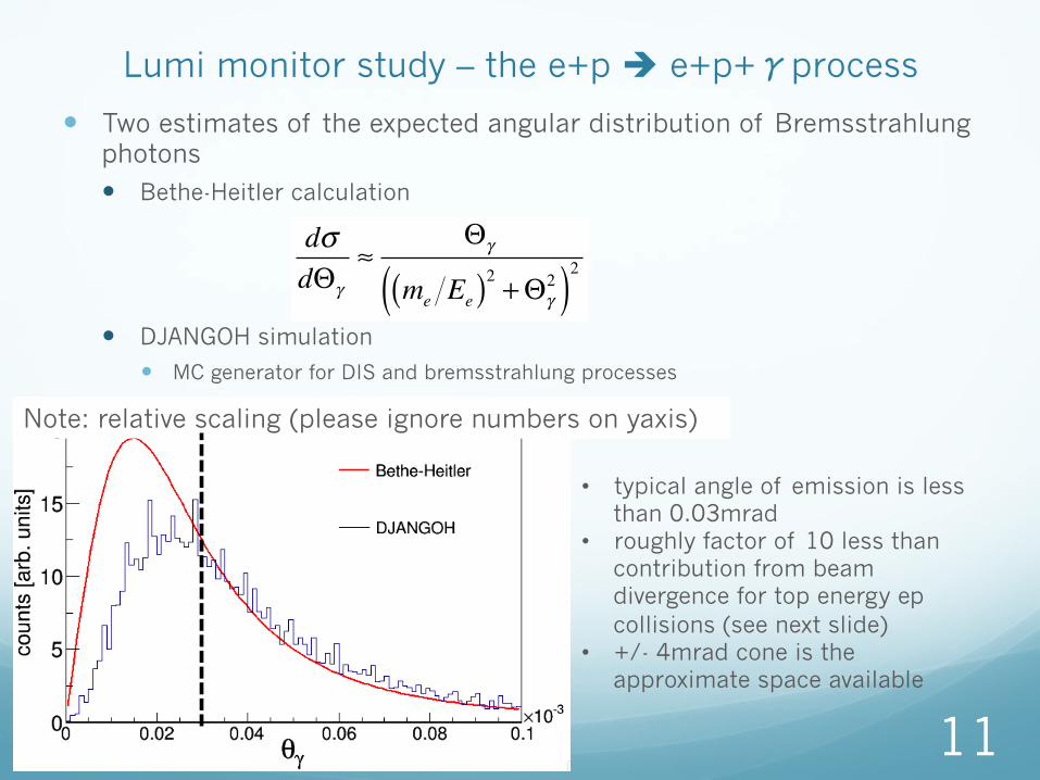
Lumi monitor study – the e+p è e+p+γprocess
� Two estimates of the expected angular distribution of Bremsstrahlung photons � Bethe-Heitler calculation
� DJANGOH simulation
� MC generator for DIS and bremsstrahlung processes
11
dσdΘγ
≈Θγ
me Ee( )2 +Θγ2( )2
Note: relative scaling (please ignore numbers on yaxis)
• typical angle of emission is less than 0.03mrad
• roughly factor of 10 less than contribution from beam divergence for top energy ep collisions (see next slide)
• +/- 4mrad cone is the approximate space available
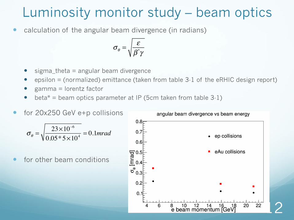
Luminosity monitor study – beam optics � calculation of the angular beam divergence (in radians)
� sigma_theta = angular beam divergence
� epsilon = (normalized) emittance (taken from table 3-1 of the eRHIC design report)
� gamma = lorentz factor
� beta* = beam optics parameter at IP (5cm taken from table 3-1)
� for 20x250 GeV e+p collisions
� for other beam conditions
12
σθ =εβ *γ
σθ =23×10−6
0.05*5×104= 0.1mrad
Conclusion for Lumi Monitor Study
� studies show that the beam conditions dominate the expected cone size of bremsstrahlung photons
� have sufficient acceptance within the current IR design
13
Low Q2-tagger Implementation
14
z = - 45m - 35m - 15m - 4m 0m 4m 18m 38m
hadrons electrons
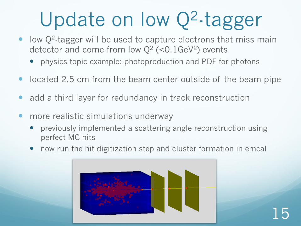
Update on low Q2-tagger � low Q2-tagger will be used to capture electrons that miss main
detector and come from low Q2 (<0.1GeV2) events � physics topic example: photoproduction and PDF for photons
� located 2.5 cm from the beam center outside of the beam pipe
� add a third layer for redundancy in track reconstruction
� more realistic simulations underway � previously implemented a scattering angle reconstruction using
perfect MC hits
� now run the hit digitization step and cluster formation in emcal
15
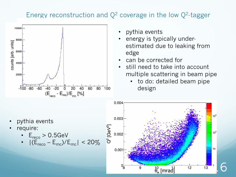
Energy reconstruction and Q2 coverage in the low Q2-tagger
16
• pythia events • energy is typically under-
estimated due to leaking from edge
• can be corrected for • still need to take into account
multiple scattering in beam pipe • to do: detailed beam pipe
design
• pythia events • require:
• Ereco > 0.5GeV • |(Ereco – Emc)/Emc| < 20%
Conclusion for Low Q2-tagger Study
� studies show reasonable energy reconstruction
� good coverage down to low Q2
17
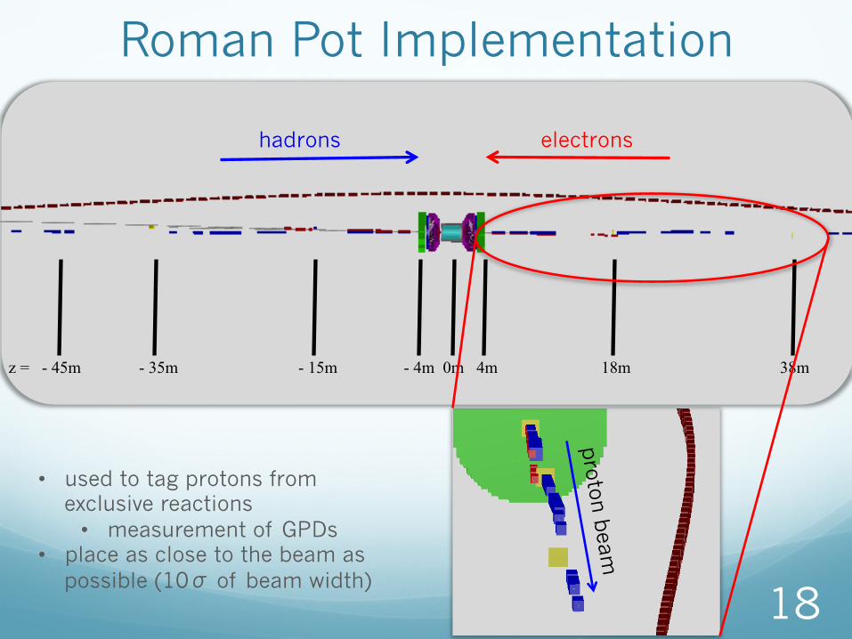
Roman Pot Implementation
18
proton
beam
z = - 45m - 35m - 15m - 4m 0m 4m 18m 38m
hadrons electrons
• used to tag protons from exclusive reactions • measurement of GPDs
• place as close to the beam as possible (10σ of beam width)
roman pot acceptance: one station at 18m � feed in MILOU simulations of DVCS events
� following studies have no beam effects taken into account and event production at (0,0,0)
� coordinates relative to the center of the beam
19
Addition of a close station at 4.25m � necessary for acceptance at high t (most statistics starved phase space)
� electron beam prevents full 360O acceptance
20
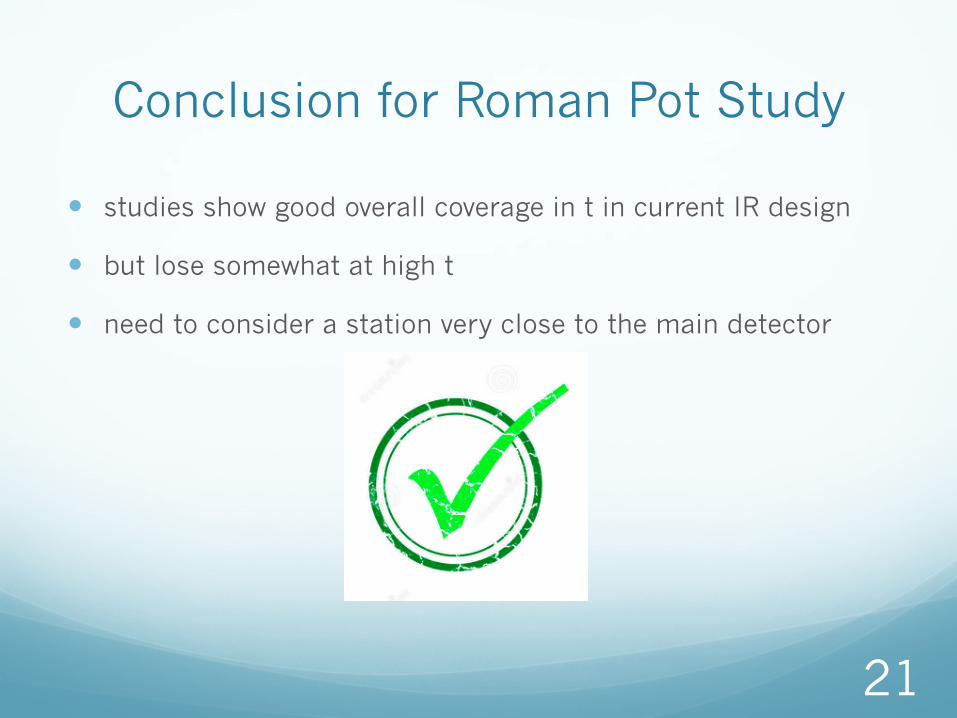
Conclusion for Roman Pot Study
� studies show good overall coverage in t in current IR design
� but lose somewhat at high t
� need to consider a station very close to the main detector
21
Electron Polarimetry � use compton-scattering process for measurement (as
was done at HERA)
� important to integrate polarimeter into the machine lattice from the beginning to minimize backgrounds � Need to find the optimal place for the detectors � reduce backgrounds from Bremsstrahlung and synchrotron
radiation � place is a short section with gentle bending
� maximize Compton rate � small crossing angle with beam � place in an area with a small electron beam width and
divergence � measure as close as possible to the IP � measure in between spin rotators
22
to do for the next year � electron polarimetry!
� calculation of polarized e+p è e+p+γ cross-section
� integrate ZDC into the design
� investigate MDISIM to improve field map importing � being developed by FCC group � interfaces MAD-X with ROOT and GEANT
� background studies (for example synchrotron radiation)
� all studies so far focused on top energy running � extend studies to lower energies
� current studies performed with v2.1 of machine design � need to iterate with a newer version (there is a v3.* in existence with some of the
concerns about apertures rectified)
� financial funding � original request 2 y of postdoc $115,508/yr + $10k/y travel funds � started August 2014 à remaining request 1 y of postdoc $115,508 + $10k travel
funds
23
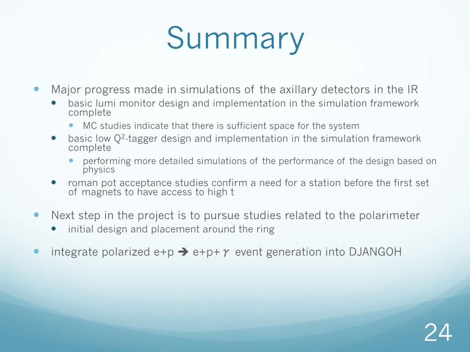
Summary
� Major progress made in simulations of the axillary detectors in the IR � basic lumi monitor design and implementation in the simulation framework
complete � MC studies indicate that there is sufficient space for the system
� basic low Q2-tagger design and implementation in the simulation framework complete � performing more detailed simulations of the performance of the design based on
physics
� roman pot acceptance studies confirm a need for a station before the first set of magnets to have access to high t
� Next step in the project is to pursue studies related to the polarimeter � initial design and placement around the ring
� integrate polarized e+p è e+p+γ event generation into DJANGOH
24
Man Power � Elke Aschenauer (BNL physics)
� Alexander Kiselev (BNL physics)
� Vladimir Litvinenko (BNL C-AD)
� Brett Parker (BNL magnet division)
� Richard Petti (BNL physics)
� Vadim Ptitsyn (BNL C-AD)
� William Schmidke (BNL physics)
� Hubert Spiesberger
� Dejan Trbojevic (BNL C-AD)
25
Backups
26
Summary at last meeting
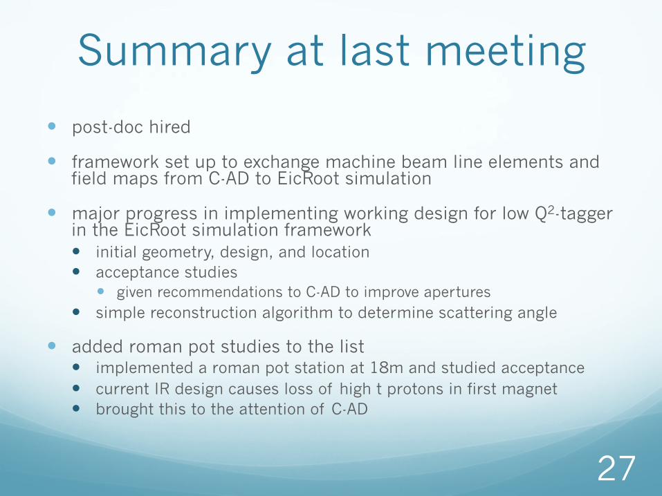
� post-doc hired
� framework set up to exchange machine beam line elements and field maps from C-AD to EicRoot simulation
� major progress in implementing working design for low Q2-tagger in the EicRoot simulation framework � initial geometry, design, and location � acceptance studies
� given recommendations to C-AD to improve apertures � simple reconstruction algorithm to determine scattering angle
� added roman pot studies to the list � implemented a roman pot station at 18m and studied acceptance � current IR design causes loss of high t protons in first magnet � brought this to the attention of C-AD
27
by Stephen Brooks
28 à space constraints need to be taken into account in detector, e-
polarimeter, lumi-monitor and tagger design design
IR-8 hall
IP
FFAG lattice
q The bypass is 2.40m outside the current RHIC IP. q The detector center line is 2.10m inside the current RHIC IP. q Relative spacing is 4.5m.
Schematic of the eRHIC IR design
Schematic of the eRHIC IR design
29
e-Beam
Hadrons
synrad
“D0”
Cryostat
Cryostat
Cryostat Cryostat Cryostat
Cryostat
Plan View of IR Layout
10 mrad crossing
Detector Region (e-beam aligned)
ZDC
Roman Pots
low Q2 tagger (not to scale)
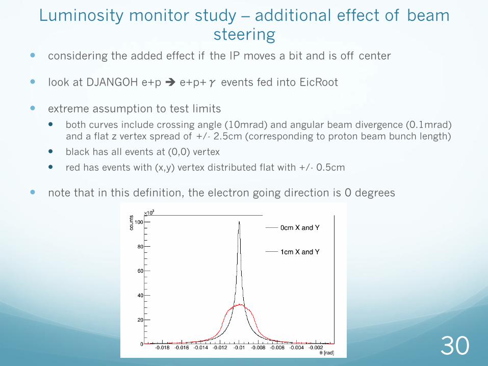
Luminosity monitor study – additional effect of beam steering
� considering the added effect if the IP moves a bit and is off center
� look at DJANGOH e+p è e+p+γ events fed into EicRoot
� extreme assumption to test limits � both curves include crossing angle (10mrad) and angular beam divergence (0.1mrad)
and a flat z vertex spread of +/- 2.5cm (corresponding to proton beam bunch length)
� black has all events at (0,0) vertex
� red has events with (x,y) vertex distributed flat with +/- 0.5cm
� note that in this definition, the electron going direction is 0 degrees
30
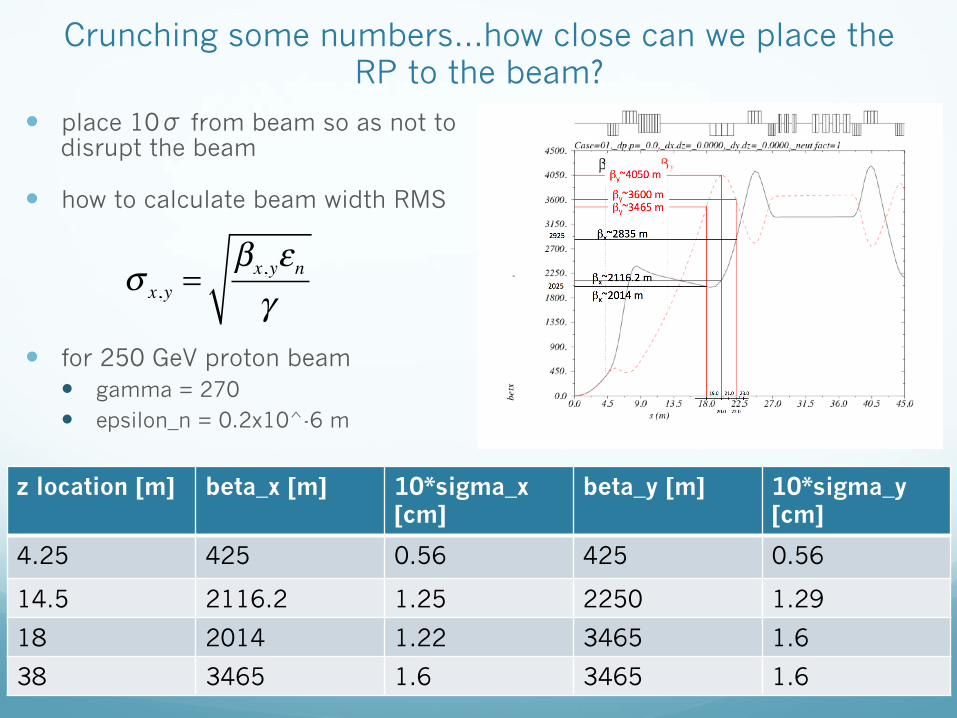
Crunching some numbers…how close can we place the RP to the beam?
� place 10σ from beam so as not to disrupt the beam
� how to calculate beam width RMS
� for 250 GeV proton beam � gamma = 270 � epsilon_n = 0.2x10^-6 m