40
Product Brochure Version 11.00 Trust your power measurements R&S®NRP POWER METER FAMILY year

Product Brochure Version 11.00
Trust your power measurements
R&S®NRP POWER METER FAMILY
year
2
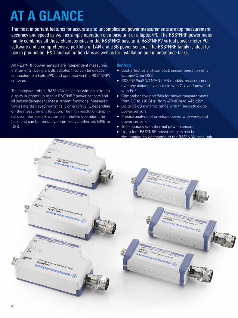
AT A GLANCEThe most important features for accurate and uncomplicated power measurements are top measurement accuracy and speed as well as simple operation on a base unit or a laptop/PC. The R&S®NRP power meter family combines all these characteristics in the R&S®NRX base unit, R&S®NRPV virtual power meter PC software and a comprehensive portfolio of LAN and USB power sensors. The R&S®NRP family is ideal for use in production, R&D and calibration labs as well as for installation and maintenance tasks.
Key facts Cost-effective and compact: sensor operation on a laptop/PC via USB
R&S®NRPxxSN/TN/AN LAN models: measurements over any distance via built-in web GUI and powered with PoE
Comprehensive portfolio for power measurements from DC to 110 GHz, from –70 dBm to +45 dBm
Up to 93 dB dynamic range with three-path diode power sensors
Precise analysis of envelope power with wideband power sensors
Top accuracy with thermal power sensors Up to four R&S®NRP power sensors can be simultaneously connected to the R&S®NRX base unit
All R&S®NRP power sensors are independent measuring instruments. Using a USB adapter, they can be directly connected to a laptop/PC and operated via the R&S®NRPV software.
The compact, robust R&S®NRX base unit with color touch display supports up to four R&S®NRP power sensors and all sensor-dependent measurement functions. Measured values are displayed numerically or graphically, depending on the measurement function. The high resolution graphi-cal user interface allows simple, intuitive operation; the base unit can be remotely controlled via Ethernet, GPIB or USB.

Rohde & Schwarz R&S®NRP Power Meter Family 3
BENEFITS AND KEY FEATURESR&S®NRX versatile, user-friendly base unit
Straightforward numerical and graphical display of measured values, plus intuitive operation
Hardware interfaces for remote control and triggering Expandable to up to four measurement channels Flexible sensor interfaces Power reflection measurements Code emulation of the R&S®NRP2 Sensor check source page 7
R&S®NRPV: convenient power measurements via PC application
Sophisticated PC application Multifunctional trace mode window Extremely flexible marker functions Intelligent licensing concept: dongle-free on multiple PCs
page 24
Versatile use of the R&S®NRP power sensorsAvailable measurement functions (modes)
Sensor type FeaturesContinuous average
TraceTimeslot/time gate
Burst average
Statistics
R&S®NRPxxS(N) three-path diode power sensors
page 11
fast, accurate and packed with features to measure CW and modulated signals
• • • • –
R&S®NRP33SN-VTVAC-compliant three-path diode power sensor
page 14
specially designed for use in thermal vacuum (TVAC) chambers
• • • • –
R&S®NRPxxT(N)/TWGthermal power sensors
page 15
most accurate power measurements for reference applications and use in calibration labs
• – – – –
R&S®NRPxxA(N)EMC average power sensors
page 18
accurate average power measurements for EMC applications
• – – – –
R&S®NRP-Z8x wideband power sensors
page 19
time domain analysis and automatic pulse analysis for radar applications and universal use
• • • • •
R&S®NRP-Z211/-Z221two-path diode power sensors
page 21
cost-effective power measurement solution for production
• • • • –
R&S®NRP-Z27/-Z37power sensor modules
page 22
level calibration of signal sources in conjunction with the R&S®FSMR measurement receiver
• – – – –
R&S®NRP-Z28/-Z98level control sensors
page 23
highly accurate signal level generation in conjunction with a signal generator
• • 1) • 1) • 1) –
1) R&S®NRP-Z28 only.
Functions and performance features Fully characterized power sensors Minimizes measurement uncertainty Intelligent averaging function minimizes measurement time
Versatile measurement functions
Additional R&S®NRPxxS(N)/T(N)/TWG/A(N) features USBTMC for easy system integration Built-in trigger I/O port Sensor status at a glance with status LED Detachable cables for flexible operation page 4
Intelligent, LAN power measurements Almost every sensor available as LAN model Remote monitoring via LAN over any distance Power supply via Power over Ethernet (PoE) Built-in web GUI with full power measurement support page 9

s11 s12
s21 s22( )
4
Intelligent averaging function minimizes measurement timeWith fixed noise averaging (an enhanced auto averaging function), any measurement can be optimized with respect to measurement time and accuracy. The aver-aging filter is dynamically set to the optimum averaging value to achieve a user-defined maximum noise content. This helps minimize measurement time and maximize production throughput for a user-specified accuracy, and simplify programming of remotely controlled measure-ment sequences.
Versatile measurement functions Continuous average mode: reliable average power measurements on CW and modulated signals
Burst average mode: burst average power measurements; sensors automatically detect start and end of a burst
Trace mode: display of envelope power versus time Timeslot mode: timeslot average power measurements on TDMA signals (e.g. GSM/EDGE)
Time gate mode: average power measurements in up to four independent time gates with user-defined position and length
FUNCTIONS AND PERFORMANCE FEATURES
Shifting the measurement plane from 1 to 2 by using S-parameter correction; the influence of upstream components is compensated
Fully characterized power sensorsThe R&S®NRPxxS(N), R&S®NRPxxT(N), R&S®NRPxxTWG, R&S®NRPxxA(N) and R&S®NRP-Zxx power sensors are immediately ready for use. In contrast to conventional power sensors, no calibration is required prior to making measurements since the sensors are fully characterized over frequency, level and temperature and feature long-term stability. All calibration data is stored in the sensors, so they function as independent measuring instruments. Usually, no zeroing is required. Users can plug in a sensor and simply start measuring.
Minimizes measurement uncertaintyEven complex test setups are no challenge for the R&S®NRPxxS(N), R&S®NRPxxT(N), R&S®NRPxxTWG, R&S®NRPxxA(N) and R&S®NRP-Zxx power sensors. Unwanted effects such as cable losses and reflections can be compensated using offset, S-parameter and Γ cor-rection. Offset correction is used to take into account frequency-independent attenuation. S-parameter correc-tion is used to mathematically shift the reference plane to the device under test (DUT) by taking into account the S-parameters of any components connected upstream of the sensor. Γ correction compensates for the effects of impedance mismatch between the source and the power sensor.
PMeas. ≠ PDUT
PDUT Couplers,attenuators,cables, etc.
Prior to S-parameter correction
S-parameter correction
After S-parameter correction
DUT
DUT
PDUT Couplers,attenuators,cables, etc.
Couplers,attenuators,cables, etc.
PMeas.
PMeas.
PMeas. = PDUT
Source
Source
Plane 2
Plane 2
Plane 1
Plane 1
Measured S-parameters S-parameters stored in sensor

Rohde & Schwarz R&S®NRP Power Meter Family 5
ADDITIONAL R&S®NRPXXS(N)/T(N)/ TWG/A(N) FEATURES
USBTMC for easy system integrationThe R&S®NRPxxS(N), R&S®NRPxxT(N), R&S®NRPxxTWG and R&S®NRPxxA(N) power sensors are USBTMC devices that can easily be integrated into automated test setups without having to install additional drivers.
R&S®NRPxxS(N), R&S®NRPxxT(N), R&S®NRPxxTWG and R&S®NRPxxA(N) power sensors can replace R&S®NRP legacy power sensors with 100 % code compatibility for remote operation.
Built-in trigger I/O portThe R&S®NRPxxS(N), R&S®NRPxxT(N), R&S®NRPxxTWG and R&S®NRPxxA(N) power sensors have integrated trigger capability. To measure power levels below the minimum trigger threshold, an external trigger signal is required. Such signals can be conveniently supplied via the built-in trigger port, which can also be used as a trig-ger output. In the trigger master mode, a trigger signal is derived from the measured signal inside the power sen-sor and output via the trigger port. This feature can be used to determine the input and output power levels of a power amplifier when the level at the amplifier input is too low for an internally triggered measurement, yet the level at the amplifier output is sufficiently high. In this case, the R&S®NRPxxS(N), R&S®NRPxxT(N), R&S®NRPxxTWG and R&S®NRPxxA(N) used for measuring the output level acts as the trigger master to trigger the input level measurement.
Sensor status at a glance with status LEDA status LED on the sensors allows the sensor status to be viewed from different angles. This is especially advanta-geous in the case of production racks with many sensors. The LED lights green to indicate error-free measurements. System-related errors, e.g. the absence of a trigger signal, are also indicated by dedicated colors. This allows users to immediately see the operating status of all sensors and quickly respond to problems.
By assigning the same color (RGB value) to a measured trace and the LED of the associated sensor, users can more easily attribute a trace to a specific sensor. This is beneficial when using multiple sensors at the same time.
Timeslot measurement of a Bluetooth® signal with exclude start time
Determination of power of an EDGE burst using an R&S®NRPxxS(N) three-path diode
power sensor and the gate function; exclusion of training sequence in the center of
the signal
Mixed display of trace and continuous average measurement

6
The R&S®NRP-ZK6 interface cable is intended for oper-ating a power sensor on the R&S®NRX base unit. It can also be used to connect the power sensor to diverse Rohde & Schwarz signal generators and signal and spec-trum analyzers to enhance these instruments with a high-performance power meter.
Multiple ways to operate the R&S®NRP power sensors
Detachable cables for flexible operationThe power sensors come with various, detachable cables for connection to diverse display units. A screw connec-tion is provided on the sensor end to prevent accidental loosening of the cable.
The R&S®NRP-ZKU USB interface cable can be used to connect a power sensor to a laptop/PC via the USB inter-face. This is an extremely space-saving and also cost-efficient solution that does not require a base unit. Two software tools – R&S®Power Viewer Plus and R&S®NRPV virtual power meter – are available to simplify sensor oper-ation from a laptop/PC. These tools support all measure-ment functions implemented in the sensors.
R&S®NRPxxS/T/TWG/A: R&S®NRP-ZKUR&S®NRPxxSN/TN/AN: R&S®NRP-ZKU or LAN
R&S®NRPxxS/T/TWG/A, R&S®NRPxxSN/TN/AN: R&S®NRP-ZK8 or R&S®NRP-ZK6
R&S®NRPxxS(N)R&S®NRPxxT(N)R&S®NRPxxTWGR&S®NRPxxA(N)
Power meterR&S®NRX
R&S®NRPxxS/T/TWG/A: R&S®NRP-ZK6 or R&S®NRP-ZKUR&S®NRPxxSN/TN/AN: R&S®NRP-ZK6 or R&S®NRP-ZKU
Signal and spectrum analyzerse.g. R&S®FSW
Network analyzerse.g. R&S®ZVA
PC/laptop with R&S®NRPV
Signal generatorse.g. R&S®SMW200A
Supported Rohde & Schwarz instruments
Power meterR&S®NRX
Signal and spectrum analyzerse.g. R&S®FSW
Network analyzerse.g. R&S®ZVA
PC/laptop with R&S®NRPV
Signal generatorse.g. R&S®SMW200A
Supported Rohde & Schwarz instruments
Connection via R&S®NRP-Z3, -Z4 or -Z5Direct connection
R&S®NRP-Zxx
Direct connection or via R&S®NRP-Z3, -Z4 or -Z5

Rohde & Schwarz R&S®NRP Power Meter Family 7
R&S®NRX VERSATILE, USER-FRIENDLY BASE UNIT
User-programmable save/recall memory locations allow fast access to personal settings. Presets for all major mobile radio standards, such as 3GPP LTE, 3GPP WCDMA, GSM/EDGE, WLAN and Bluetooth®, ensure cor-rect measurement with a minimum of keystrokes.
The 5" TFT color display supports the intuitive, window based operating concept. Key parameters and functions are color-coded and can be seen at a glance.
Results are presented in numerical and graphical display windows that can be easily configured.
In the continuous average, burst average, timeslot and time gate average measurement modes, up to four numer-ical results can be displayed in parallel. The ratio, SWR, return loss and reflection coefficient can be calculated from two measurement channels using predefined com-putation functions and displayed in addition to the abso-lute and relative power level.
Trace measurements and statistical measurements are presented in graphical windows. The trace mode allows simultaneous display of two traces in one measurement window. Level differences and time offset can be seen at a glance and accurately measured using horizontal and ver-tical markers. It is also possible to display the ratio of two traces.
Timeslots and time gates as well as the associated mea-surement values (average, peak or crest factor) can be graphically displayed in the trace window.
All R&S®NRP-Z8x wideband power sensors allow auto-matic pulse analysis. Up to 12 of 18 user-selected pulse parameters can be displayed in addition to the measure-ment trace.
The statistical amplitude distribution of the envelope power is shown as CCDF, CDF or PDF in a statistics window.
R&S®NRX displays up to four measurements simultaneously
Automatic pulse analysis with the R&S®NRX and R&S®NRP-Z81
R&S®NRX power meter with connected
R&S®NRP-Z81 wideband power sensor
Straightforward numerical and graphical display of measured values, plus intuitive operation The R&S®NRX simultaneously supports up to four power sensors of the R&S®NRP and R&S®NRQ family. Function keys on the front panel provide quick access to the most important functions. Users can open the frequency set-ting menu or zero the connected sensors at the push of a button.

8
Expandable to up to four measurement channels The R&S®NRX standard configuration includes one mea-surement channel. The base unit can be optionally expanded to two (R&S®NRX-K2, software option) or four (R&S®NRX-K2 and R&S®NRX-K4, software options) mea-surement channels.
Flexible sensor interfacesThe R&S®NRX provides two sensor connectors on the front and optionally two additional sensor connectors on the rear (R&S®NRX-B4, hardware option). A USB 2.0 inter-face on the front and the rear provides further connectivity (USB power sensors, memory key, mouse or keyboard).
Power reflection measurementsThe R&S®NRX optionally provides the R&S®NRX-B9 inter-face for the R&S®NRT2 directional power sensors.
Code emulation of the R&S®NRP2The R&S®NRX can interpret the command set of its prede-cessor, the R&S®NRP2.
Sensor check sourceAn optional high-precision 50 MHz/1 GHz reference source module (R&S®NRX-B1 sensor check source) can be used in CW mode to check the function of all R&S®NRP power sensors. In pulse mode, the test generator can be used to check the pulse measurement performance of the R&S®NRP-Z8x wideband power sensors or the R&S®NRQ frequency selective power sensor.
Hardware interfaces for remote control and triggering The R&S®NRX provides three different remote interfaces for integration in automated test setups: Ethernet, USB and optionally GPIB (R&S®NRX-B8).
A trigger input on the rear panel permits external trig-gering for synchronized power measurements. Using an R&S®NRP-Z81, for example, a trigger signal can be derived from the measurement signal and output at the trigger output (trigger master mode). A level-proportional voltage or a digital signal for limit monitoring can be output via BNC connectors.
R&S®NRX rear view
The modular concept allows users to choose between
the R&S®NRX-B9 or the R&S®NRX-B1 option.

Rohde & Schwarz R&S®NRP Power Meter Family 9
Almost every sensor available as LAN modelAlmost every R&S®NRPxxS three-path diode, R&S®NRPxxA average and R&S®NRPxxT thermal sensor from the R&S®NRP product range is available as a LAN model (R&S®NRPxxSN, R&S®NRPxxAN, R&S®NRPxxTN). LAN models are equipped with an additional LAN interface without compromising sensor features and performance.
Remote monitoring via LAN over any distanceThe R&S®NRPxxSN, R&S®NRPxxTN and R&S®NRPxxAN LAN power sensors are ideal for remote monitoring appli-cations, e.g. for satellite systems or particle accelerators, where sensors need to be placed at different points in the system. The LAN interface makes it easy to overcome large distances between the various test points and the control center.
INTELLIGENT, LAN POWER MEASUREMENTS
LAN interface, trigger I/O port and detachable cable for the R&S®NRPxxSN sensors
Operation of R&S®NRPxxSN power sensor via a web browser

10
Power supply via Power over Ethernet (PoE)In LAN operation, the sensors are powered via a PoE- capable LAN interface on the power sensor. If the LAN used does not support the PoE standard, then the sensors are connected to the LAN via a PoE+ compliant switch.
Built-in web GUI with full power measurement supportThe R&S®NRPxxSN, R&S®NRPxxTN and R&S®NRPxxAN can be operated via a web interface. Using a PC con-nected to the internet, the power sensors can be conve-niently controlled via a web browser – no additional soft-ware needs to be installed.
Simultaneous, location-independent remote monitoring of multiple R&S®NRPxxSN/TN/AN power sensors using a web browser
Mobileinternet
PoE switch
WLAN
R&S®NRPxxSN/TN/AN
DUT
LAN
WLANInternet
PoE switch R&S®NRPxxSN/TN/AN
DUT

Rohde & Schwarz R&S®NRP Power Meter Family 11
The R&S®NRP40S(N) and R&S®NRP50S(N) are ideal for measurements on microwave link systems operating at frequencies up to 50 GHz. The user benefits from short measurement times and the sensors’ wide dynamic range.
The R&S®NRP67S(N) supports frequencies up to 67 GHz including IEEE 802.11ad and IEEE 802.11ay.
93 dB dynamic range thanks to improved three-path conceptThe R&S®NRPxxS(N) power sensors use three separate diode paths, each operated in the optimum detector range. As a result, the average power can be determined with high accuracy irrespective of the modulation type. Measurement results are hardly affected by interfering signals or harmonics. The R&S®NRPxxS(N) power sensors therefore behave similar to thermal power sensors but offer significantly higher speed. They provide up to 93 dB dynamic range with an excellent lower measurement limit of –70 dBm.
THREE-PATH DIODE POWER SENSORS
Sensor type Frequency range Level range Connector typeR&S®NRP8S(N) 10 MHz to 8 GHz –70 dBm to +23 dBm N (m)
R&S®NRP18S(N) 10 MHz to 18 GHz –70 dBm to +23 dBm N (m)
R&S®NRP33S(N) 10 MHz to 33 GHz –70 dBm to +23 dBm 3.5 mm (m)
R&S®NRP40S(N) 50 MHz to 40 GHz –70 dBm to +20 dBm 2.92 mm (m)
R&S®NRP50S(N) 50 MHz to 50 GHz –70 dBm to +20 dBm 2.4 mm (m)
R&S®NRP67S(N) 50 MHz to 67 GHz –70 dBm to +20 dBm 1.85 mm (m)
R&S®NRP18S-10 10 MHz to 18 GHz –60 dBm to +33 dBm N (m)
R&S®NRP18S-20 10 MHz to 18 GHz –50 dBm to +42 dBm N (m)
R&S®NRP18S-25 10 MHz to 18 GHz –45 dBm to +45 dBm N (m)
R&S®NRP50S and R&S®NRP50SN
three-path diode power sensors
Ideal for universal applicationsThree-path diode power sensors are suitable for numer-ous applications since they support continuous average, burst average, timeslot average, gate average and trace measurements. Featuring outstanding performance and unprecedented measurement speed and accuracy, the sensors can be used to perform precise average power measurements on wireless signals ranging from GSM and LTE up to 5G NR. For detailed analysis, the sensors offer additional measurement functions such as timeslot mode and trace mode with a video bandwidth of 100 kHz.
Offering a frequency range of up to 33 GHz, the R&S®NRP33S(N) is ideal for use in the automotive sector, for example in the development and production of long-range and short-range anti-collision radars (24 GHz). It is also a perfect choice for installation, maintenance and remote monitoring of ground stations for satellite systems (up to 33 GHz).

AD
+
AD
AD
12
Unlike conventional multipath technology, adjacent diode paths in the R&S®NRPxxS(N) power sensors overlap by 6 dB. All paths are continuously and simultaneously measured. The final measurement result is achieved by appropriately weighting the measurement results of all paths. This innovative approach ensures a smooth transi-tion between measurement paths. Problems due to hard switching between the measurement paths, such as hys-teresis effects, additional measurement delays and dif-ferential nonlinearity, are eliminated. The patented sensor architecture also improves the signal-to-noise ratio and increases measurement speed in the transition region.
Unprecedented measurement speed and accuracy even at low levelsThe measurement speed is not only a function of the sam-pling rate. It depends to a substantial degree on the level to be measured and the desired measurement accuracy. To increase measurement accuracy, especially at low lev-els, it is necessary to average multiple measured values. While averaging reduces the noise component and thus increases measurement accuracy, it also slows down the measurement. The R&S®NRPxxS(N) power sensors have therefore been designed with an extremely low measure-ment noise in mind.
As a basic rule, it can be said that a 50 % reduction in the measurement noise will reduce the measurement time by a factor of four while maintaining the same accuracy.
With a typical measurement noise of 20 pW, the R&S®NRPxxS(N) power sensors can perform measure-ments down to a lower limit of –70 dBm with the highest speed and accuracy currently available on the market.
More than 50 000 readings/sWith more than 50 000 readings/s in fast continuous aver-age mode, the R&S®NRPxxS(N) power sensors are cur-rently the fastest sensors on the market. In buffered mode, they can transmit up to 8192 measured values per block with a minimum aperture of 10 µs. This corresponds to a continuous acquisition time of 81.92 ms. Any sporadic interference will be reliably detected.
Innovative three-path concept
–20 dBmto +6 dBm
Error correction
34 dB
Chopper
14 dB
Weighting
External trigger
–70 dBmto –14 dBm
0 dBmto +23 dBm
Pi Pm

Rohde & Schwarz R&S®NRP Power Meter Family 13
10 000 triggered measurements/sIn fast continuous average mode, the R&S®NRPxxS(N) power sensors can perform up to 10 000 triggered measurements/s with a minimum trigger repetition time of 100 µs without losing any measurement. This measurement speed is achieved by using the buffered mode. In buffered mode, all measured data is collected inside the sensor and transmitted in one block to the sensor’s host. By exploiting the maximum buffer size, the R&S®NRPxxS(N) sensors are able to collect measured data for up to 8192 triggered measurements within 0.81 s.
Sensors for high-power applicationsThe R&S®NRP18S-10, R&S®NRP18S-20 and R&S®NRP18S-25 high-power three-path diode power sensors consist of an R&S®NRP18S and a 10/20/25 dB upstream attenuator. They are able to perform power mea-surements up to 2 W, 15 W and 30 W.
When used with the attenuator, mismatch errors between the sensor and attenuator are automatically corrected. The S-parameters for the attenuator are determined and stored in the sensor during production. They are then automati-cally taken into account when performing measurements.
Triggered measurements
R&S®NRP18S-10, R&S®NRP18S-20 and R&S®NRP18S-25
high-power three-path diode power sensors for high-power
applications up to 30 W
Time
Minimum trigger repetition time: 100 μs
Variable triggered measurement points
Trigger signal (variable trigger repetition)

14
The R&S®NRPxxSN-V and R&S®NRP67SN-V TVAC-compliant power sensors cover the satellite communica-tions frequency range up to 67 GHz and allow fast, highly accurate power measurements over a dynamic range of up to 93 dB, independent of signal bandwidth and modu-lation type. Thanks to their LAN capability, the power sen-sors can be easily controlled and monitored from outside the chamber.
A set of dedicated, TVAC compliant cables is available as well. These cables are made of vacuum friendly mate-rial. Additionally, they are baked and come in vacuumized packaging. These measures ensure optimal performance in TVAC environments and prevent any gassing or contamination.
TVAC-COMPLIANT THREE-PATH DIODE POWER SENSOR
Sensor type Frequency range Level range Connector typeR&S®NRP33SN-V 10 MHz to 33 GHz –70 dBm to +23 dBm 3.5 mm (m)
R&S®NRP67SN-V 50 MHz to 67 GHz –70 dBm to +20 dBm 1.85 mm (m)
R&S®NRP67SN-V
TVAC-compliant
power sensor
Specially designed for use in thermal vacuum (TVAC) chambersIn the satellite sector, components, subsystems and entire satellites must be qualified in a thermal vacuum (TVAC) before they can be used in space. This increasingly requires highly accurate, reliable power measurements directly on the DUT, i.e. in a TVAC chamber. Power sensors must therefore not only function in a high vacuum but also be able to withstand certain temperature fluctuations.
The R&S®NRPxxSN-V and R&S®NRP67SN-V TVAC-compliant power sensors are specially designed for these requirements. All components are baked in a vacuum chamber during the production process, so outgassing is reduced to a minimum. Venting holes in the housing ensure pressure equalization between the inside of the sensor and the environment.

Rohde & Schwarz R&S®NRP Power Meter Family 15
The R&S®NRPxxT(N) thermal power sensors feature an unparalleled linearity of 0.007 dB (0.16 %) up to 67 GHz and 0.010 dB (0.23 %) between 67 GHz and 110 GHz. The R&S®NRPxxTWG thermal power sensors feature a linearity of 0.010 dB (0.23 %) between 50 GHz and 110 GHz – the ideal choice for performing relative measurements.
These sensor characteristics are particularly beneficial in reference applications and calibration labs.
Excellent impedance matchingTo a large extent, measurement uncertainty results from multiple reflections at the source and power sensor caused by mismatch. To minimize these reflections, all thermal power sensors in the R&S®NRP family are excel-lently matched up to high frequencies, reducing measure-ment uncertainty.
THERMAL POWER SENSORS
Sensor type Frequency range Level range Connector typeR&S®NRP18T(N) DC to 18 GHz –35 dBm to +20 dBm N (m)
R&S®NRP33T(N) DC to 33 GHz –35 dBm to +20 dBm 3.5 mm (m)
R&S®NRP40T(N) DC to 40 GHz –35 dBm to +20 dBm 2.92 mm (m)
R&S®NRP50T(N) DC to 50 GHz –35 dBm to +20 dBm 2.4 mm (m)
R&S®NRP67T(N) DC to 67 GHz –35 dBm to +20 dBm 1.85 mm (m)
R&S®NRP90T(N) DC to 90 GHz –35 dBm to +20 dBm 1.35 mm (m)
R&S®NRP110T DC to 110 GHz –35 dBm to +20 dBm 1 mm (m)
R&S®NRP75TWG 50 GHz to 75 GHz –35 dBm to +20 dBm WR15
R&S®NRP90TWG 60 GHz to 90 GHz –35 dBm to +20 dBm WR12
R&S®NRP110TWG 75 GHz to 110 GHz –35 dBm to +20 dBm WR10
R&S®NRP67T and R&S®NRP67TN thermal power sensor
Outstanding performance for reference applicationsThermal power sensors are especially used for complex measurement tasks where highest accuracy counts. They tolerate any type of modulation. To improve measurement accuracy, the hardware of the R&S®NRPxxT(N)/TWG ther-mal power sensors is designed to reduce measurement noise to a minimum and to make the sensor immune to thermal environmental effects. To achieve stable mea-surement results, the temperature in the thermal test cell must correspond to the applied power. When the power is increased, the sophisticated measurement cell of the R&S®NRPxxT(N)/TWG thermal power sensors quickly attains a stable temperature. When the power level is decreased, the excess heat is dissipated extremely quickly. Consequently, thermal power sensors from Rohde & Schwarz are able to measure three times faster than comparable solutions on the market with triggered measurements and > 500 measurements/s in buffered mode – with top accuracy.

16
R&S®NRPxxTWG with waveguide interfaceNew, high-frequency technologies such as satellite com-munications, research and military radar targeting and tracking, and some non-military applications such as auto-motive radar create a challenging situation for the required test setup.
R&S®NRP75TWG/90TWG/110TWG
thermal power sensors
R&S®NRP110T thermal
power sensor with
waveguide adapter and
bracket
The R&S®NRPxxTWG thermal power sensors provide a convenient and accurate solution with integrated wave-guide interfaces.
Waveguide adapters and a waveguide bracket are avail-able for the R&S®NRP110T sensor.

Rohde & Schwarz R&S®NRP Power Meter Family 17
Sophisticated coaxial connector conceptThanks to the innovative connector design, the sensors can be easily screw-connected to the signal source to be measured. A ball bearing in the coupling nut ensures that only the coupling nut has to be turned to tighten the sen-sor. The sensor body stays fixed in the required position. Contrary to conventional connecting screws, the outer conductors of the sensor and DUT are not turned rela-tive to each other and so their mating surfaces do not rub together. This reduces wear and enhances reproducibility of measurements. The connector concept contributes to high measurement accuracy.
Internal calibration testRohde & Schwarz has implemented a special verification function in the R&S®NRPxxT(N)/TWG sensors. This func-tion covers all essential components of the signal path. Using a test routine, the sensor’s response to a highly sta-ble applied DC power is measured and compared to the value stored during the previous calibration. The result pro-vides information about the functionality and accuracy of the power sensor.
Interior view of the connector
Coupling nut
Outer connector Supporting beadsInner connector Transducer
Ball bearing

18
EMC AVERAGE POWER SENSORSSpecially designed for EMC applicationsIn EMC applications, usually only the average power is of interest. This is where the R&S®NRPxxA(N) average power sensors are the perfect fit. They cover measurement ranges that are used in telecommunications as well as the important lower frequency bands down to 8 kHz. Users benefit from the excellent properties of the three-path diode power sensors, including a dynamic range of up to 93 dB, very low influence of the modulation on the mea-surement and outstanding impedance matching.
Sensor type Frequency range Level range Connector typeR&S®NRP6A(N) 8 kHz to 6 GHz –70 dBm to +23 dBm N (m)
R&S®NRP18A(N) 8 kHz to 18 GHz –70 dBm to +23 dBm N (m)
R&S®NRP18A and R&S®NRP18AN
EMC average power sensor

Rohde & Schwarz R&S®NRP Power Meter Family 19
WIDEBAND POWER SENSORSOutstanding dynamic range and accuracyThe dynamic range of the R&S®NRP-Z8x wideband power sensors yields a lower limit of –47 dBm for enve-lope power measurements and –60 dBm for average power measurements. This sensitivity is unique and so far unprecedented on the market. Users benefit from enhanced reproducibility and high measurement speed.
These sensors are therefore ideal for analyzing envelope power as well as for measuring average power.
High resolution modeSome applications require the display of strongly magni-fied signal sections such as the rising edge of a pulse. To improve the graphical display in the trace mode, which has a resolution of 12.5 ns, a high density of samples is required. Equivalent time sampling with repetitive signals can achieve a time resolution of up to 100 ps.
Highest measurement speedThe R&S®NRP-Z8x wideband power sensors are the world’s fastest sensors. In buffered mode, a specified measurement speed of > 9000 measurements/s can be achieved.
Sensor type Frequency range Measurement range Connector typeR&S®NRP-Z81 50 MHz to 18 GHz –60 dBm to +20 dBm N
R&S®NRP-Z85 50 MHz to 40 GHz –60 dBm to +20 dBm 2.92 mm
R&S®NRP-Z86,model .40
50 MHz to 40 GHz –60 dBm to +20 dBm 2.4 mm
R&S®NRP-Z86,model .44
50 MHz to 44 GHz –60 dBm to +20 dBm 2.4 mm
R&S®NRP-Z81/-Z85/-Z86 wideband power sensors
Ideal for radar applicationsThe R&S®NRP-Z8x wideband power sensors are ideal for radar applications. In development or during installation and maintenance, pulse characteristics as well as out-put power have to be measured. Similar measurements are required in the production of radar systems and radar components. Thanks to a maximum video bandwidth of 30 MHz and a rise/fall time < 13 ns, the sensors can mea-sure pulses with a pulse width as small as 50 ns.
Up to 44 GHzThe R&S®NRP-Z8x wideband power sensors are ideal for power measurements on microwave link modules. Especially the R&S®NRP-Z86 model .44 (upper frequency limit of 44 GHz) can be used for the development, produc-tion, installation and maintenance of the latest genera-tion of microwave link modules. The user benefits from the sensor’s high measurement speed and large dynamic range.

20
Statistical analysis The R&S®NRP-Z8x wideband power sensors permit statisti-cal analysis of the amplitude distribution of noise-like sig-nals to determine key parameters such as peak envelope power, average power and peak-to-average power ratio. The measurement data supports the design of compo-nents for modern OFDM or CDMA based wireless systems such as EUTRA/LTE and 3GPP FDD. Using one million samples, the R&S®NRP-Z8x wideband power sensors can measure the CCDF, CDF or PDF in less than 25 ms at full video bandwidth.
It is also possible to perform statistical analysis on an indi-vidually configured time gate so that only specific signal sections are observed.
Trigger master mode (with base unit or R&S®NRP-Z5)Combined with the R&S®NRX base unit or the R&S®NRP-Z5 sensor hub, an R&S®NRP-Z8x wideband power sensor can be used as a trigger source. In the trig-ger master mode, a trigger signal is derived from the measured signal inside the power sensor and forwarded to the base unit or sensor hub for further use. All other connected sensors can be externally triggered using this trigger signal. An additional external trigger source is not required. This feature can be used to determine the input and output level of power amplifiers when the level at the input is too low for an internally triggered mea-surement, yet the level at the output is sufficient. In this case, an R&S®NRP-Z8x used for measuring the output signal acts as the trigger master to trigger the input signal measurement.
Time parameters
Level parameters
Automatic pulse analysisAutomatic pulse analysis supports users in measuring important pulse parameters. It eliminates the need for complex measurements using markers; changes in the pulse shape are immediately taken into account in the measurement results.
The following parameters are determined by automatic pulse analysis:
Time parameters: rise/fall time, start/stop time, pulse width, duty cycle, pulse period, pulse off time
Level parameters: pulse top, pulse base, peak, average, minimum, overshoot (positive and negative)
Calculated value:Duty cycle
Time
Pow
er
High ref. level(distal)
Start time
Rise time
Off timePulse width
Pulse period
Ref. level(mesial)
Low ref. level(proximal)
Fall time
Stop time
Calculated value:Positive overshootNegative overshoot
Time
Pow
er
Peak powerPulse top power
Average power
Base powerMin. power

Rohde & Schwarz R&S®NRP Power Meter Family 21
TWO-PATH DIODE POWER SENSORSMid-class sensor with tried and tested technology The two-path diode power sensors use the tried and tested Rohde & Schwarz multipath technology. With two overlap-ping diode paths measured in parallel and a wide dynamic range of 80 dB, the power sensors feature high measure-ment accuracy and speed.
Sensor type Frequency range Measurement range Connector typeR&S®NRP-Z211 10 MHz to 8 GHz –60 dBm to +20 dBm N
R&S®NRP-Z221 10 MHz to 18 GHz –60 dBm to +20 dBm N
R&S®NRP-Z211/-Z221 two-path diode power sensors
Cost-effective solution for production applicationsThe R&S®NRP-Z211/-Z221 two-path diode power sensors combine all key characteristics relevant for their use in pro-duction. These USB sensors are cost-effective, fast and precise. The sensors support the same measurement func-tions as the R&S®NRPxxS three-path diode power sensors and offer the best price/performance ratio in their class.

22
POWER SENSOR MODULESan integrated power splitter, the power is fed to the inte-grated R&S®NRP-Z27/-Z37 thermal power sensor module and simultaneously to the measuring receiver via a phase-stable cable.
Like all other power sensors in the R&S®NRP family, the power sensor modules are fully self-contained power meters that are remotely controlled from the R&S®FSMR, R&S®NRX or any Windows PC via USB.
Sensor type Frequency range Measurement range Connector typeR&S®NRP-Z27 DC to 18 GHz –24 dBm to +26 dBm N
R&S®NRP-Z37 DC to 26.5 GHz –24 dBm to +26 dBm 3.5 mm
R&S®FSMR measuring receiver with R&S®NRP-Z27 power sensor module
R&S®FSMR measuring receiver with R&S®NRP-Z27/-Z37 power sensor module
Solution for accurate level calibrationThe R&S®NRP-Z27/-Z37 power sensor modules turn the R&S®FSMR measuring receivers into precision power meters with a wide dynamic range from –115 dBm to +30 dBm.
The R&S®NRP-Z27/-Z37 power sensor modules were developed especially for level calibration using the R&S®FSMR measuring receiver. These sensors act as highly accurate references for determining the absolute power level. Together with the excellent linearity of the R&S®FSMR, this enables precise power calibration over the entire level range of the measuring receiver. Using
R&S®NRP-Z27/-Z37 power sensor
modules
R&S®FSMRmeasuring receiver
R&S®NRP-Z27/-Z37power sensor module
Source

Rohde & Schwarz R&S®NRP Power Meter Family 23
LEVEL CONTROL SENSORSR&S®NRX base unit or on a laptop/PC. The other part, which is identical to the measured part, is output at the sensor's RF output and can be directly fed to the DUT. The sensor is a permanent part of the test setup. To per-form a power measurement, it is not necessary to discon-nect the DUT from the RF source. Uncertainties caused by a mismatched load or the cable loss between the sig-nal generator and the DUT are prevented by using the R&S®NRP-Z28/-Z98 level control sensors together with the automatic level correction feature of Rohde & Schwarz sig-nal generators. Distances of up to 1.2 m are bridged by an integrated low-loss microwave cable.
Sensor type Frequency range Measurement range Connector typeR&S®NRP-Z28 10 MHz to 18 GHz –67 dBm to +20 dBm N
R&S®NRP-Z98 9 kHz to 6 GHz –67 dBm to +20 dBm N
R&S®NRP-Z28/-Z98 level
control sensors
Feeding accurate power level to a device under test (DUT)The R&S®NRP-Z28/-Z98 level control sensors were devel-oped especially to feed power to the DUT and monitor the power at the same time. The sensor's integrated power splitter splits the signal into two equal power parts. One part is measured by the integrated power sensor and dis-played on a Rohde & Schwarz signal generator, on the

24
Multifunctional trace mode windowThe trace mode is supported by all three-path diode power sensors, two-path diode power sensors and wideband power sensors. Up to four trace measurements and four mathematical traces can be simultaneously displayed in one window.
Timeslot/time gateTimeslot and time gate measurements are performed directly in the trace window. The R&S®NRPV virtual power meter software supports up to 16 timeslots and four inde-pendent time gates. They can be transparently displayed in the trace window. Timeslot and gate length as well as their starting position are adjusted using the mouse; mea-sured values are displayed as a table in the measurement window.
R&S®NRPV: CONVENIENT POWER MEASUREMENTS VIA PC APPLICATION
Gated measurement of two GSM/EDGE traces with the R&S®NRP-Z81
Sophisticated PC applicationIn combination with the R&S®NRPV virtual power meter software, the USB capability of the R&S®NRP power sen-sors can be ideally utilized. The software covers all sensor functions and supports up to four sensors connected to a laptop/PC via the R&S®NRP-Z3/-Z4 USB adapter cables or the R&S®NRP-Z5 sensor hub. The sensors are automati-cally detected when plugged in and added to all open measurement windows (hot plugging).
This cost-effective measurement solution supports all available measurement modes. Mathematical calculations during measurements to determine the SWR, difference or ratio are possible in the continuous average, gated average and burst average numerical modes and in the graphical trace mode.

Rohde & Schwarz R&S®NRP Power Meter Family 25
Intelligent licensing concept: dongle-free on multiple PCsThe R&S®NRPV virtual power meter software can be installed on an unlimited number of laptops/PCs. All R&S®NRPxxS(N)/T(N)/A(N) sensors come from the fac-tory enabled for use with the R&S®NRPV software. Each R&S®NRP-Zxx sensor has to be activated individually using the sensor-specific R&S®NRPZ-K1 keycode option. Once activated, the sensor can be operated on any laptop/PC. This licensing concept eliminates the need for USB don-gles and does not tie a license to a specific laptop/PC.
Pulse delay measurement on different traces
Automatic pulse analysisThe R&S®NRP-Z8x wideband power sensors can quickly and automatically analyze pulsed signals in trace mode to continuously determine the most important time and power parameters.
Extremely flexible marker functionsThe marker function in the trace mode supports an unlim-ited number of markers that can be linked together as required. In addition to single markers (to measure the level at a fixed time) and double markers (to determine the level difference after a fixed time period), other functions such as automatic peak search are available.
Each marker can be used as a reference marker and func-tions as a reference point to determine time and level dif-ferences. Linked markers can be combined and extended as required. Since each marker is associated with a trace, markers from different traces can also be linked. The spac-ing between two pulses in different traces can be accu-rately and continuously measured, even if the pulse spac-ing changes.
Complex marker settings can be stored and retrieved at any time.

26
The power sensor also provides a fence function for the timeslot and time gate modes. The fence can be config-ured separately for each gate or globally for all timeslots. This allows the user to keep track of the power at all times during the time segments of interest. Exclude times can be set to mask interfering signal components at the edges of a timeslot.
Power measurements in radiocommunications standardsRadiocommunications standards such as 3GPP LTE, 3GPP FDD and CDMA2000® exhibit very different power profiles depending on their channel utilization. Assessing these power profiles is a routine job with the power sen-sors in the R&S®NRP family. This is true no matter whether you need to accurately measure the average power, peak power, peak-to-average ratio in the time domain or you need fast statistical analysis to precisely determine the amplitude distribution.
Average power measurements are possible with all R&S®NRP power sensors. The R&S®NRPxxT thermal power sensors are used when highest accuracy is required. The R&S®NRPxxS/xxA/-Z2xx multipath sensors perform aver-age power measurements very quickly over a dynamic range of up to 93 dB. This is true even for signals with a high peak-to-average ratio. Thanks to the patented multipath technology, measurements are always fast and accurate even at the limits of the measurement paths. The innovative sensor architecture eliminates measurement range switching as well as the associated discontinuity in the measured values and extended measurement times.
For power analysis, the R&S®NRP-Z8x wideband power sensors are available. With a maximum video bandwidth of 30 MHz, these sensors are ideal for analyzing noise-like signals in statistic mode. Exact determination of the ampli-tude statistics permits accurate peak, average and crest factor measurements.
Radar applicationsThe R&S®NRP-Z8x wideband power sensors with a maxi-mum frequency of 44 GHz are ideal for time domain analy-sis of pulses. Automatic pulse analysis enables users to continuously monitor key pulse parameters such as rise/fall time, pulse width or pulse top without interaction. With a rise time of 13 ns, even steep edges can be mea-sured. This performance is sufficient to measure most radar signals.
Even nonrepetitive pulse sequences where each pulse exhibits a different power level can be precisely measured.
APPLICATIONS
Measurement of eight timeslots in one shot with the R&S®NRPV
Statistical analysis of an LTE signal using the R&S®NRPV
Accurate measurement of TDMA based signalsThe analysis of TDMA based signals encountered in GSM/EDGE and DECT is a common application for power measurements. The R&S®NRPxxS/-Z2xx/-Z8x sensors are very powerful tools for such work. The trace mode makes graphical analysis of any signal very straightforward. The ability to easily modify the time axis and the auto scaling function provide useful support during in-depth analysis of relevant signal components. The time slot measurement in the trace mode allows simultaneous analysis of multiple equidistant timeslots.
Additionally, the R&S®NRPxxS/-Z2xx/-Z8x sensors support up to four independent measurement gates. Start time and length can be individually configured for each gate.

Rohde & Schwarz R&S®NRP Power Meter Family 27
Using the sensor’s buffered mode, the measurements are performed so fast that it is possible to reliably measure the power of all pulses even in the presence of high pulse rep-etition rates and short pulses. This ensures reliable detec-tion of even rarely occurring signal phenomena.
Component tests with high throughputIn component testing, the focus is on precisely determin-ing the input/output power, the gain, and the input imped-ance matching of the DUT. The R&S®NRP family provides an outstanding solution for such applications. Only one R&S®NRX base unit with up to four measurement chan-nels is required for the simultaneous evaluation of the results delivered by the sensors. This makes it possible to correctly measure the input and output power of a power amplifier as well as to accurately determine the gain and input impedance matching since the R&S®NRX base unit automatically calculates the power ratios.
R&S®NRP-Z8x wideband power sensors
are suitable for accurate measurement
of pulsed radar systems.
Typical test setup for multicarrier power amplifier (MCPA) tests; calculation functions of the R&S®NRX allow impedance matching and gain to be determined
R&S®SMW200Avector signal generator
50 Ωtermination
R&S®NRPpower sensor A,input power
Directionalcoupler DUT
Powerattenuator
Powerattenuator
R&S®FSWsignal and spectrum analyzer
R&S®NRPpower sensor B,reflected power
R&S®NRPpower sensor C,output power
R&S®NRXbase unit
Directionalcoupler
Directionalcoupler
50 Ωtermination
50 Ωtermination

28
SPECIFICATIONS IN BRIEFSpecifications in briefSensor type, connector Frequency range Power measurement range, maximum input power Impedance matching (SWR) Rise time, video bandwidth Uncertainty for power measurements at +20 °C to +25 °C Sensor type, connector
absolute (in dB) relative (in dB)Three-path diode power sensors Three-path diode power sensorsR&S®NRP8S(N)N (m)
10 MHz to 8 GHz100 pW to 200 mW(–70 dBm to +23 dBm)
10 MHz to 2.4 GHz: < 1.13> 2.4 GHz to 8.0 GHz: < 1.20
< 5 µs> 100 kHz
0.053 to 0.065 0.022 to 0.050R&S®NRP8S(N)N (m)
R&S®NRP18S(N)N (m)
10 MHz to 18 GHz100 pW to 200 mW(–70 dBm to +23 dBm)
10 MHz to 2.4 GHz: < 1.13> 2.4 GHz to 8.0 GHz: < 1.20> 8.0 GHz to 18.0 GHz: < 1.25
0.053 to 0.094 0.022 to 0.069R&S®NRP18S(N)N (m)
R&S®NRP33S(N)3.5 mm (m)
10 MHz to 33 GHz100 pW to 200 mW(–70 dBm to +23 dBm)
10 MHz to 2.4 GHz: < 1.13> 2.4 GHz to 8.0 GHz: < 1.20> 8.0 GHz to 18.0 GHz: < 1.25> 18.0 GHz to 26.5 GHz: < 1.30> 26.5 GHz to 33.0 GHz: < 1.35
0.053 to 0.134 0.022 to 0.136R&S®NRP33S(N)3.5 mm (m)
R&S®NRP40S(N)2.92 mm (m)
50 MHz to 40 GHz100 pW to 100 mW(–70 dBm to +20 dBm)
50 MHz to 2.4 GHz: < 1.13> 2.4 GHz to 8.0 GHz: < 1.20> 8.0 GHz to 18.0 GHz: < 1.25> 18.0 GHz to 26.5 GHz: < 1.30> 26.5 GHz to 33.0 GHz: < 1.35> 33 GHz to 40.0 GHz: < 1.37
0.073 to 0.138 0.028 to 0.142R&S®NRP40S(N)2.92 mm (m)
R&S®NRP50S(N)2.4 mm (m)
50 MHz to 50 GHz100 pW to 100 mW(–70 dBm to +20 dBm)
50 MHz to 2.4 GHz: < 1.13> 2.4 GHz to 8.0 GHz: < 1.20> 8.0 GHz to 18.0 GHz: < 1.25> 18.0 GHz to 26.5 GHz: < 1.30> 26.5 GHz to 33.0 GHz: < 1.35> 33 GHz to 40.0 GHz: < 1.37> 40 GHz to 50.0 GHz: < 1.40
0.073 to 0.183 0.028 to 0.184R&S®NRP50S(N)2.4 mm (m)
R&S®NRP67S(N)1.85 mm (m)
50 MHz to 67 GHz100 pW to 100 mW (–70 dBm to +20 dBm)
50 MHz to 200 MHz: < 1.30> 200 MHz to 2.4 GHz: < 1.13> 2.4 GHz to 8.0 GHz: < 1.20 > 8.0 GHz to 18.0 GHz: < 1.25> 18.0 GHz to 26.5 GHz: < 1.30> 26.5 GHz to 33.0 GHz: < 1.35> 33.0 GHz to 40.0 GHz: < 1.37> 40.0 GHz to 50.0 GHz: < 1.40> 50.0 GHz to 67.0 GHz: < 1.68
0.073 to 0.255 0.028 to 0.266R&S®NRP67S(N)1.85 mm (m)
High-power three-path diode power sensor High-power three-path diode power sensor
R&S®NRP18S-10N (m)
10 MHz to 18 GHz1 nW to 2 W(–60 dBm to +33 dBm)
10 MHz to 2.4 GHz: < 1.14> 2.4 GHz to 8.0 GHz: < 1.20> 8.0 GHz to 12.4 GHz: < 1.25> 12.4 GHz to 18.0 GHz: < 1.30
< 5 µs> 100 kHz
0.083 to 0.198 0.022 to 0.087R&S®NRP18S-10N (m)
R&S®NRP18S-20N (m)
10 MHz to 18 GHz10 nW to 15 W(–50 dBm to +42 dBm)
10 MHz to 2.4 GHz: < 1.14> 2.4 GHz to 8.0 GHz: < 1.25> 8.0 GHz to 12.4 GHz: < 1.30> 12.4 GHz to 18.0 GHz: < 1.41
0.083 to 0.198 0.022 to 0.087R&S®NRP18S-20N (m)
R&S®NRP18S-25N (m)
10 MHz to 18 GHz30 nW to 30 W(–45 dBm to +45 dBm)
10 MHz to 2.4 GHz: < 1.14> 2.4 GHz to 8.0 GHz: < 1.25> 8.0 GHz to 12.4 GHz: < 1.30> 12.4 GHz to 18.0 GHz: < 1.41
0.083 to 0.219 0.022 to 0.087R&S®NRP18S-25N (m)
TVAC-compliant three-path diode power sensors TVAC-compliant three-path diode power sensor
R&S®NRP33SN-V3.5 mm (m)
10 MHz to 33 GHz100 pW to 200 mW(–70 dBm to +23 dBm)
10 MHz to 2.4 GHz: < 1.13> 2.4 GHz to 8.0 GHz: < 1.20> 8.0 GHz to 18.0 GHz: < 1.25> 18.0 GHz to 26.5 GHz: < 1.30> 26.5 GHz to 33.0 GHz: < 1.35
< 5 µs> 100 kHz
0.053 to 0.134 0.022 to 0.136R&S®NRP33SN-V3.5 mm (m)
R&S®NRP67SN-V1.85 mm (m)
50 MHz to 67 GHz100 pW to 100 mW (–70 dBm to +20 dBm)
50 MHz to 200 MHz: < 1.30> 200 MHz to 2.4 GHz: < 1.13> 2.4 GHz to 8.0 GHz: < 1.20 > 8.0 GHz to 18.0 GHz: < 1.25> 18.0 GHz to 26.5 GHz: < 1.30> 26.5 GHz to 33.0 GHz: < 1.35> 33.0 GHz to 40.0 GHz: < 1.37> 40.0 GHz to 50.0 GHz: < 1.40> 50.0 GHz to 67.0 GHz: < 1.68
0.073 to 0.255 0.028 to 0.266R&S®NRP67SN-V1.85 mm (m)

Rohde & Schwarz R&S®NRP Power Meter Family 29
Specifications in briefSensor type, connector Frequency range Power measurement range, maximum input power Impedance matching (SWR) Rise time, video bandwidth Uncertainty for power measurements at +20 °C to +25 °C Sensor type, connector
absolute (in dB) relative (in dB)Three-path diode power sensors Three-path diode power sensorsR&S®NRP8S(N)N (m)
10 MHz to 8 GHz100 pW to 200 mW(–70 dBm to +23 dBm)
10 MHz to 2.4 GHz: < 1.13> 2.4 GHz to 8.0 GHz: < 1.20
< 5 µs> 100 kHz
0.053 to 0.065 0.022 to 0.050R&S®NRP8S(N)N (m)
R&S®NRP18S(N)N (m)
10 MHz to 18 GHz100 pW to 200 mW(–70 dBm to +23 dBm)
10 MHz to 2.4 GHz: < 1.13> 2.4 GHz to 8.0 GHz: < 1.20> 8.0 GHz to 18.0 GHz: < 1.25
0.053 to 0.094 0.022 to 0.069R&S®NRP18S(N)N (m)
R&S®NRP33S(N)3.5 mm (m)
10 MHz to 33 GHz100 pW to 200 mW(–70 dBm to +23 dBm)
10 MHz to 2.4 GHz: < 1.13> 2.4 GHz to 8.0 GHz: < 1.20> 8.0 GHz to 18.0 GHz: < 1.25> 18.0 GHz to 26.5 GHz: < 1.30> 26.5 GHz to 33.0 GHz: < 1.35
0.053 to 0.134 0.022 to 0.136R&S®NRP33S(N)3.5 mm (m)
R&S®NRP40S(N)2.92 mm (m)
50 MHz to 40 GHz100 pW to 100 mW(–70 dBm to +20 dBm)
50 MHz to 2.4 GHz: < 1.13> 2.4 GHz to 8.0 GHz: < 1.20> 8.0 GHz to 18.0 GHz: < 1.25> 18.0 GHz to 26.5 GHz: < 1.30> 26.5 GHz to 33.0 GHz: < 1.35> 33 GHz to 40.0 GHz: < 1.37
0.073 to 0.138 0.028 to 0.142R&S®NRP40S(N)2.92 mm (m)
R&S®NRP50S(N)2.4 mm (m)
50 MHz to 50 GHz100 pW to 100 mW(–70 dBm to +20 dBm)
50 MHz to 2.4 GHz: < 1.13> 2.4 GHz to 8.0 GHz: < 1.20> 8.0 GHz to 18.0 GHz: < 1.25> 18.0 GHz to 26.5 GHz: < 1.30> 26.5 GHz to 33.0 GHz: < 1.35> 33 GHz to 40.0 GHz: < 1.37> 40 GHz to 50.0 GHz: < 1.40
0.073 to 0.183 0.028 to 0.184R&S®NRP50S(N)2.4 mm (m)
R&S®NRP67S(N)1.85 mm (m)
50 MHz to 67 GHz100 pW to 100 mW (–70 dBm to +20 dBm)
50 MHz to 200 MHz: < 1.30> 200 MHz to 2.4 GHz: < 1.13> 2.4 GHz to 8.0 GHz: < 1.20 > 8.0 GHz to 18.0 GHz: < 1.25> 18.0 GHz to 26.5 GHz: < 1.30> 26.5 GHz to 33.0 GHz: < 1.35> 33.0 GHz to 40.0 GHz: < 1.37> 40.0 GHz to 50.0 GHz: < 1.40> 50.0 GHz to 67.0 GHz: < 1.68
0.073 to 0.255 0.028 to 0.266R&S®NRP67S(N)1.85 mm (m)
High-power three-path diode power sensor High-power three-path diode power sensor
R&S®NRP18S-10N (m)
10 MHz to 18 GHz1 nW to 2 W(–60 dBm to +33 dBm)
10 MHz to 2.4 GHz: < 1.14> 2.4 GHz to 8.0 GHz: < 1.20> 8.0 GHz to 12.4 GHz: < 1.25> 12.4 GHz to 18.0 GHz: < 1.30
< 5 µs> 100 kHz
0.083 to 0.198 0.022 to 0.087R&S®NRP18S-10N (m)
R&S®NRP18S-20N (m)
10 MHz to 18 GHz10 nW to 15 W(–50 dBm to +42 dBm)
10 MHz to 2.4 GHz: < 1.14> 2.4 GHz to 8.0 GHz: < 1.25> 8.0 GHz to 12.4 GHz: < 1.30> 12.4 GHz to 18.0 GHz: < 1.41
0.083 to 0.198 0.022 to 0.087R&S®NRP18S-20N (m)
R&S®NRP18S-25N (m)
10 MHz to 18 GHz30 nW to 30 W(–45 dBm to +45 dBm)
10 MHz to 2.4 GHz: < 1.14> 2.4 GHz to 8.0 GHz: < 1.25> 8.0 GHz to 12.4 GHz: < 1.30> 12.4 GHz to 18.0 GHz: < 1.41
0.083 to 0.219 0.022 to 0.087R&S®NRP18S-25N (m)
TVAC-compliant three-path diode power sensors TVAC-compliant three-path diode power sensor
R&S®NRP33SN-V3.5 mm (m)
10 MHz to 33 GHz100 pW to 200 mW(–70 dBm to +23 dBm)
10 MHz to 2.4 GHz: < 1.13> 2.4 GHz to 8.0 GHz: < 1.20> 8.0 GHz to 18.0 GHz: < 1.25> 18.0 GHz to 26.5 GHz: < 1.30> 26.5 GHz to 33.0 GHz: < 1.35
< 5 µs> 100 kHz
0.053 to 0.134 0.022 to 0.136R&S®NRP33SN-V3.5 mm (m)
R&S®NRP67SN-V1.85 mm (m)
50 MHz to 67 GHz100 pW to 100 mW (–70 dBm to +20 dBm)
50 MHz to 200 MHz: < 1.30> 200 MHz to 2.4 GHz: < 1.13> 2.4 GHz to 8.0 GHz: < 1.20 > 8.0 GHz to 18.0 GHz: < 1.25> 18.0 GHz to 26.5 GHz: < 1.30> 26.5 GHz to 33.0 GHz: < 1.35> 33.0 GHz to 40.0 GHz: < 1.37> 40.0 GHz to 50.0 GHz: < 1.40> 50.0 GHz to 67.0 GHz: < 1.68
0.073 to 0.255 0.028 to 0.266R&S®NRP67SN-V1.85 mm (m)

30
Specifications in briefSensor type, connector Frequency range Power measurement range, maximum input power Impedance matching (SWR) Rise time, video bandwidth Uncertainty for power measurements at +20 °C to +25 °C Sensor type, connector
absolute (in dB) relative (in dB)Thermal power sensors Thermal power sensors
R&S®NRP18T(N)N (m)
DC to 18 GHz 300 nW to 100 mW (–35 dBm to +20 dBm)
DC to 100 MHz: < 1.03> 100 MHz to 2.4 GHz: < 1.06> 2.4 GHz to 12.4 GHz: < 1.13> 12.4 GHz to 18.0 GHz: < 1.16
–
0.040 to 0.082 0.010R&S®NRP18T(N)N (m)
R&S®NRP33T(N)3.5 mm (m)
DC to 33 GHz 300 nW to 100 mW (–35 dBm to +20 dBm)
DC to 100 MHz: < 1.03> 100 MHz to 2.4 GHz: < 1.06> 2.4 GHz to 12.4 GHz: < 1.13> 12.4 GHz to 18.0 GHz: < 1.16> 18.0 GHz to 26.5 GHz: < 1.22> 26.5 GHz to 33.0 GHz: < 1.28
0.040 to 0.101 0.010R&S®NRP33T(N)3.5 mm (m)
R&S®NRP40T(N)2.92 mm (m)
DC to 40 GHz 300 nW to 100 mW (–35 dBm to +20 dBm)
DC to 100 MHz: < 1.03> 100 MHz to 2.4 GHz: < 1.06> 2.4 GHz to 12.4 GHz: < 1.13> 12.4 GHz to 18.0 GHz: < 1.16> 18.0 GHz to 26.5 GHz: < 1.22> 26.5 GHz to 40.0 GHz: < 1.28
0.040 to 0.108 0.010R&S®NRP40T(N)2.92 mm (m)
R&S®NRP50T(N)2.4 mm (m)
DC to 50 GHz 300 nW to 100 mW (–35 dBm to +20 dBm)
DC to 100 MHz: < 1.03> 100 MHz to 2.4 GHz: < 1.06> 2.4 GHz to 12.4 GHz: < 1.13> 12.4 GHz to 18.0 GHz: < 1.16> 18.0 GHz to 26.5 GHz: < 1.22> 26.5 GHz to 40.0 GHz: < 1.28> 40.0 GHz to 50.0 GHz: < 1.30
0.040 to 0.143 0.010R&S®NRP50T(N)2.4 mm (m)
R&S®NRP67T(N)1.85 mm (m)
DC to 67 GHz 300 nW to 100 mW (–35 dBm to +20 dBm)
DC to 100 MHz: < 1.03> 100 MHz to 2.4 GHz: < 1.06> 2.4 GHz to 12.4 GHz: < 1.13> 12.4 GHz to 18.0 GHz: < 1.16> 18.0 GHz to 26.5 GHz: < 1.22> 26.5 GHz to 40.0 GHz: < 1.28> 40.0 GHz to 50.0 GHz: < 1.30> 50.0 GHz to 67.0 GHz: < 1.35
0.040 to 0.209 0.010R&S®NRP67T(N)1.85 mm (m)
R&S®NRP90T(N)1.35 mm (m)
DC to 90 GHz 300 nW to 100 mW (–35 dBm to +20 dBm)
DC to 100 MHz: < 1.05> 100 MHz to 2.4 GHz: < 1.08> 2.4 GHz to 12.4 GHz: < 1.18> 12.4 GHz to 18.0 GHz: < 1.23> 18.0 GHz to 26.5 GHz: < 1.28> 26.5 GHz to 40.0 GHz: < 1.38> 40.0 GHz to 50.0 GHz: < 1.46> 50.0 GHz to 67.0 GHz: < 1.56> 67.0 GHz to 80.0 GHz: < 1.60> 80.0 GHz to 90.0 GHz: < 1.66
0.040 to 0.269 0.014R&S®NRP90T(N)1.35 mm (m)
R&S®NRP110T1 mm (m)
DC to 110 GHz 300 nW to 100 mW (–35 dBm to +20 dBm)
DC to 100 MHz: < 1.05> 100 MHz to 2.4 GHz: < 1.08> 2.4 GHz to 12.4 GHz: < 1.18> 12.4 GHz to 18.0 GHz: < 1.23> 18.0 GHz to 26.5 GHz: < 1.28> 26.5 GHz to 40.0 GHz: < 1.38> 40.0 GHz to 50.0 GHz: < 1.46> 50.0 GHz to 67.0 GHz: < 1.56> 67.0 GHz to 80.0 GHz: < 1.60> 80.0 GHz to 95.0 GHz: < 1.66> 95.0 GHz to 110 GHz: < 1.70
0.040 to 0.290 0.014R&S®NRP110T1 mm (m)
Thermal waveguide power sensors Thermal waveguide power sensorsR&S®NRP75TWG WR15
50 GHz to 75 GHz 300 nW to 100 mW (–35 dBm to +20 dBm)
–
0.190 0.014R&S®NRP75TWG WR15
R&S®NRP90TWGWR12
60 GHz to 90 GHz 300 nW to 100 mW (–35 dBm to +20 dBm) 0.194 0.014R&S®NRP90TWGWR12
R&S®NRP110TWGWR10
75 GHz to 110 GHz 300 nW to 100 mW (–35 dBm to +20 dBm) 0.198 0.014R&S®NRP110TWGWR10

Rohde & Schwarz R&S®NRP Power Meter Family 31
Specifications in briefSensor type, connector Frequency range Power measurement range, maximum input power Impedance matching (SWR) Rise time, video bandwidth Uncertainty for power measurements at +20 °C to +25 °C Sensor type, connector
absolute (in dB) relative (in dB)Thermal power sensors Thermal power sensors
R&S®NRP18T(N)N (m)
DC to 18 GHz 300 nW to 100 mW (–35 dBm to +20 dBm)
DC to 100 MHz: < 1.03> 100 MHz to 2.4 GHz: < 1.06> 2.4 GHz to 12.4 GHz: < 1.13> 12.4 GHz to 18.0 GHz: < 1.16
–
0.040 to 0.082 0.010R&S®NRP18T(N)N (m)
R&S®NRP33T(N)3.5 mm (m)
DC to 33 GHz 300 nW to 100 mW (–35 dBm to +20 dBm)
DC to 100 MHz: < 1.03> 100 MHz to 2.4 GHz: < 1.06> 2.4 GHz to 12.4 GHz: < 1.13> 12.4 GHz to 18.0 GHz: < 1.16> 18.0 GHz to 26.5 GHz: < 1.22> 26.5 GHz to 33.0 GHz: < 1.28
0.040 to 0.101 0.010R&S®NRP33T(N)3.5 mm (m)
R&S®NRP40T(N)2.92 mm (m)
DC to 40 GHz 300 nW to 100 mW (–35 dBm to +20 dBm)
DC to 100 MHz: < 1.03> 100 MHz to 2.4 GHz: < 1.06> 2.4 GHz to 12.4 GHz: < 1.13> 12.4 GHz to 18.0 GHz: < 1.16> 18.0 GHz to 26.5 GHz: < 1.22> 26.5 GHz to 40.0 GHz: < 1.28
0.040 to 0.108 0.010R&S®NRP40T(N)2.92 mm (m)
R&S®NRP50T(N)2.4 mm (m)
DC to 50 GHz 300 nW to 100 mW (–35 dBm to +20 dBm)
DC to 100 MHz: < 1.03> 100 MHz to 2.4 GHz: < 1.06> 2.4 GHz to 12.4 GHz: < 1.13> 12.4 GHz to 18.0 GHz: < 1.16> 18.0 GHz to 26.5 GHz: < 1.22> 26.5 GHz to 40.0 GHz: < 1.28> 40.0 GHz to 50.0 GHz: < 1.30
0.040 to 0.143 0.010R&S®NRP50T(N)2.4 mm (m)
R&S®NRP67T(N)1.85 mm (m)
DC to 67 GHz 300 nW to 100 mW (–35 dBm to +20 dBm)
DC to 100 MHz: < 1.03> 100 MHz to 2.4 GHz: < 1.06> 2.4 GHz to 12.4 GHz: < 1.13> 12.4 GHz to 18.0 GHz: < 1.16> 18.0 GHz to 26.5 GHz: < 1.22> 26.5 GHz to 40.0 GHz: < 1.28> 40.0 GHz to 50.0 GHz: < 1.30> 50.0 GHz to 67.0 GHz: < 1.35
0.040 to 0.209 0.010R&S®NRP67T(N)1.85 mm (m)
R&S®NRP90T(N)1.35 mm (m)
DC to 90 GHz 300 nW to 100 mW (–35 dBm to +20 dBm)
DC to 100 MHz: < 1.05> 100 MHz to 2.4 GHz: < 1.08> 2.4 GHz to 12.4 GHz: < 1.18> 12.4 GHz to 18.0 GHz: < 1.23> 18.0 GHz to 26.5 GHz: < 1.28> 26.5 GHz to 40.0 GHz: < 1.38> 40.0 GHz to 50.0 GHz: < 1.46> 50.0 GHz to 67.0 GHz: < 1.56> 67.0 GHz to 80.0 GHz: < 1.60> 80.0 GHz to 90.0 GHz: < 1.66
0.040 to 0.269 0.014R&S®NRP90T(N)1.35 mm (m)
R&S®NRP110T1 mm (m)
DC to 110 GHz 300 nW to 100 mW (–35 dBm to +20 dBm)
DC to 100 MHz: < 1.05> 100 MHz to 2.4 GHz: < 1.08> 2.4 GHz to 12.4 GHz: < 1.18> 12.4 GHz to 18.0 GHz: < 1.23> 18.0 GHz to 26.5 GHz: < 1.28> 26.5 GHz to 40.0 GHz: < 1.38> 40.0 GHz to 50.0 GHz: < 1.46> 50.0 GHz to 67.0 GHz: < 1.56> 67.0 GHz to 80.0 GHz: < 1.60> 80.0 GHz to 95.0 GHz: < 1.66> 95.0 GHz to 110 GHz: < 1.70
0.040 to 0.290 0.014R&S®NRP110T1 mm (m)
Thermal waveguide power sensors Thermal waveguide power sensorsR&S®NRP75TWG WR15
50 GHz to 75 GHz 300 nW to 100 mW (–35 dBm to +20 dBm)
–
0.190 0.014R&S®NRP75TWG WR15
R&S®NRP90TWGWR12
60 GHz to 90 GHz 300 nW to 100 mW (–35 dBm to +20 dBm) 0.194 0.014R&S®NRP90TWGWR12
R&S®NRP110TWGWR10
75 GHz to 110 GHz 300 nW to 100 mW (–35 dBm to +20 dBm) 0.198 0.014R&S®NRP110TWGWR10

32
Specifications in briefSensor type, connector Frequency range Power measurement range, maximum input power Impedance matching (SWR) Rise time, video bandwidth Uncertainty for power measurements at +20 °C to +25 °C Sensor type, connector
absolute (in dB) relative (in dB)Average power sensors Average power sensors
R&S®NRP6A(N)N (m)
8 kHz to 6 GHz100 pW to 200 mW(–70 dBm to +23 dBm)
8 kHz to < 20 kHz: < 1.2520 kHz to 2.4 GHz: < 1.13> 2.4 GHz to 6 GHz: < 1.20
–
0.051 to 0.056 0.022 to 0.050R&S®NRP6A(N)N (m)
R&S®NRP18A(N)N (m)
8 kHz to 18 GHz100 pW to 200 mW(–70 dBm to +23 dBm)
8 kHz to < 20 kHz: < 1.2520 kHz to 2.4 GHz: < 1.13> 2.4 GHz to 6 GHz: < 1.20> 8 GHz to 18 GHz: < 1.25
0.051 to 0.094 0.022 to 0.069R&S®NRP18A(N)N (m)
Wideband power sensors Wideband power sensors
R&S®NRP-Z81 N (m)
50 MHz to 18 GHz1 nW to 100 mW (–60 dBm to +20 dBm)max. 200 mW (AVG)/1 W (PK, 1 µs)
50 MHz to 2.4 GHz: < 1.16> 2.4 GHz to 8.0 GHz: < 1.20> 8.0 GHz to 18.0 GHz: < 1.25
< 13 ns> 30 MHz
0.130 to 0.150 0.039 to 0.148R&S®NRP-Z81 N (m)
R&S®NRP-Z85 2.92 mm (m)
50 MHz to 40 GHz1 nW to 100 mW (–60 dBm to +20 dBm)max. 200 mW (AVG)/1 W (PK, 1 µs)
50 MHz to 2.4 GHz: < 1.16> 2.4 GHz to 8.0 GHz: < 1.20> 8.0 GHz to 18.0 GHz: < 1.25> 18.0 GHz to 26.5 GHz: < 1.30> 26.5 GHz to 40.0 GHz: < 1.35
0.130 to 0.180 0.039 to 0.165R&S®NRP-Z85 2.92 mm (m)
R&S®NRP-Z86 2.4 mm (m)
50 MHz to 40 GHz1 nW to 100 mW (–60 dBm to +20 dBm)max. 200 mW (AVG)/1 W (PK, 1 µs)
50 MHz to 2.4 GHz: < 1.16> 2.4 GHz to 8.0 GHz: < 1.20> 8.0 GHz to 18.0 GHz: < 1.25> 18.0 GHz to 26.5 GHz: < 1.30> 26.5 GHz to 40.0 GHz: < 1.35
0.130 to 0.180 0.039 to 0.165R&S®NRP-Z86 2.4 mm (m)
R&S®NRP-Z862.4 mm (m)
50 MHz to 44 GHz1 nW to 100 mW (–60 dBm to +20 dBm)max. 200 mW (AVG)/1 W (PK, 1 µs)
50 MHz to 2.4 GHz: < 1.16> 2.4 GHz to 8.0 GHz: < 1.20> 8.0 GHz to 18.0 GHz: < 1.25> 18.0 GHz to 26.5 GHz: < 1.30> 26.5 GHz to 40.0 GHz: < 1.35> 40.0 GHz to 44.0 GHz: < 1.40
0.130 to 0.190 0.039 to 0.165R&S®NRP-Z862.4 mm (m)
Two-path diode power sensors Two-path diode power sensors
R&S®NRP-Z211 N (m)
10 MHz to 8 GHz1.0 nW to 100 mW (–60 dBm to +20 dBm)max. 400 mW (AVG)/2 W (PK, 10 µs)
10 MHz to 2.4 GHz: < 1.13> 2.4 GHz to 8.0 GHz: < 1.20
< 10 µs> 40 kHz
0.054 to 0.110 0.022 to 0.112R&S®NRP-Z211 N (m)
R&S®NRP-Z221 N (m)
10 MHz to 18 GHz1.0 nW to 100 mW (–60 dBm to +20 dBm)max. 400 mW (AVG)/2 W (PK, 10 µs)
10 MHz to 2.4 GHz: < 1.13> 2.4 GHz to 8.0 GHz: < 1.20> 8.0 GHz to 18.0 GHz: < 1.25
0.054 to 0.143 0.022 to 0.142R&S®NRP-Z221 N (m)
Power sensor modules Power sensor modules
R&S®NRP-Z27 N (m)
DC to 18 GHz4 µW to 400 mW (–24 dBm to +26 dBm)max. 500 mW (AVG)/30 W (PK, 1 µs)
DC to 2.0 GHz: < 1.15> 2.0 GHz to 4.2 GHz: < 1.18> 4.2 GHz to 8.0 GHz: < 1.23> 8.0 GHz to 12.4 GHz: < 1.25> 12.4 GHz to 18.0 GHz: < 1.35
–
0.070 to 0.112 0.032R&S®NRP-Z27 N (m)
R&S®NRP-Z37 3.5 mm (m)
DC to 26.5 GHz4 µW to 400 mW (–24 dBm to +26 dBm)max. 500 mW (AVG)/30 W (PK, 1 µs)
DC to 2.0 GHz: < 1.15> 2.0 GHz to 4.2 GHz: < 1.18> 4.2 GHz to 8.0 GHz: < 1.23> 8.0 GHz to 12.4 GHz: < 1.25> 12.4 GHz to 18.0 GHz: < 1.30> 18.0 GHz to 26.5 GHz: < 1.45
0.070 to 0.122 0.032R&S®NRP-Z37 3.5 mm (m)
Level control sensors Level control sensors
R&S®NRP-Z28 N (m)
10 MHz to 18 GHz200 pW to 100 mW (–67 dBm to +20 dBm)max. 700 mW (AVG)/4 W (PK, 10 µs)
10 MHz to 2.4 GHz: < 1.11> 2.4 GHz to 4.0 GHz: < 1.15> 4.0 GHz to 8.0 GHz: < 1.22> 8.0 GHz to 18 GHz: < 1.30
< 8 µs> 50 kHz
0.047 to 0.130 0.022 to 0.110R&S®NRP-Z28 N (m)
R&S®NRP-Z98 N (m)
9 kHz to 6 GHz200 pW to 100 mW (–67 dBm to +20 dBm)max. 700 mW (AVG)/4 W (PK, 10 µs)
9 kHz to 2.4 GHz: < 1.11> 2.4 GHz to 4.0 GHz: < 1.15> 4.0 GHz to 6.0 GHz: < 1.22
– 0.047 to 0.083 0.022 to 0.066R&S®NRP-Z98 N (m)
For data sheet, see PD 3607.0852.22

Rohde & Schwarz R&S®NRP Power Meter Family 33
Specifications in briefSensor type, connector Frequency range Power measurement range, maximum input power Impedance matching (SWR) Rise time, video bandwidth Uncertainty for power measurements at +20 °C to +25 °C Sensor type, connector
absolute (in dB) relative (in dB)Average power sensors Average power sensors
R&S®NRP6A(N)N (m)
8 kHz to 6 GHz100 pW to 200 mW(–70 dBm to +23 dBm)
8 kHz to < 20 kHz: < 1.2520 kHz to 2.4 GHz: < 1.13> 2.4 GHz to 6 GHz: < 1.20
–
0.051 to 0.056 0.022 to 0.050R&S®NRP6A(N)N (m)
R&S®NRP18A(N)N (m)
8 kHz to 18 GHz100 pW to 200 mW(–70 dBm to +23 dBm)
8 kHz to < 20 kHz: < 1.2520 kHz to 2.4 GHz: < 1.13> 2.4 GHz to 6 GHz: < 1.20> 8 GHz to 18 GHz: < 1.25
0.051 to 0.094 0.022 to 0.069R&S®NRP18A(N)N (m)
Wideband power sensors Wideband power sensors
R&S®NRP-Z81 N (m)
50 MHz to 18 GHz1 nW to 100 mW (–60 dBm to +20 dBm)max. 200 mW (AVG)/1 W (PK, 1 µs)
50 MHz to 2.4 GHz: < 1.16> 2.4 GHz to 8.0 GHz: < 1.20> 8.0 GHz to 18.0 GHz: < 1.25
< 13 ns> 30 MHz
0.130 to 0.150 0.039 to 0.148R&S®NRP-Z81 N (m)
R&S®NRP-Z85 2.92 mm (m)
50 MHz to 40 GHz1 nW to 100 mW (–60 dBm to +20 dBm)max. 200 mW (AVG)/1 W (PK, 1 µs)
50 MHz to 2.4 GHz: < 1.16> 2.4 GHz to 8.0 GHz: < 1.20> 8.0 GHz to 18.0 GHz: < 1.25> 18.0 GHz to 26.5 GHz: < 1.30> 26.5 GHz to 40.0 GHz: < 1.35
0.130 to 0.180 0.039 to 0.165R&S®NRP-Z85 2.92 mm (m)
R&S®NRP-Z86 2.4 mm (m)
50 MHz to 40 GHz1 nW to 100 mW (–60 dBm to +20 dBm)max. 200 mW (AVG)/1 W (PK, 1 µs)
50 MHz to 2.4 GHz: < 1.16> 2.4 GHz to 8.0 GHz: < 1.20> 8.0 GHz to 18.0 GHz: < 1.25> 18.0 GHz to 26.5 GHz: < 1.30> 26.5 GHz to 40.0 GHz: < 1.35
0.130 to 0.180 0.039 to 0.165R&S®NRP-Z86 2.4 mm (m)
R&S®NRP-Z862.4 mm (m)
50 MHz to 44 GHz1 nW to 100 mW (–60 dBm to +20 dBm)max. 200 mW (AVG)/1 W (PK, 1 µs)
50 MHz to 2.4 GHz: < 1.16> 2.4 GHz to 8.0 GHz: < 1.20> 8.0 GHz to 18.0 GHz: < 1.25> 18.0 GHz to 26.5 GHz: < 1.30> 26.5 GHz to 40.0 GHz: < 1.35> 40.0 GHz to 44.0 GHz: < 1.40
0.130 to 0.190 0.039 to 0.165R&S®NRP-Z862.4 mm (m)
Two-path diode power sensors Two-path diode power sensors
R&S®NRP-Z211 N (m)
10 MHz to 8 GHz1.0 nW to 100 mW (–60 dBm to +20 dBm)max. 400 mW (AVG)/2 W (PK, 10 µs)
10 MHz to 2.4 GHz: < 1.13> 2.4 GHz to 8.0 GHz: < 1.20
< 10 µs> 40 kHz
0.054 to 0.110 0.022 to 0.112R&S®NRP-Z211 N (m)
R&S®NRP-Z221 N (m)
10 MHz to 18 GHz1.0 nW to 100 mW (–60 dBm to +20 dBm)max. 400 mW (AVG)/2 W (PK, 10 µs)
10 MHz to 2.4 GHz: < 1.13> 2.4 GHz to 8.0 GHz: < 1.20> 8.0 GHz to 18.0 GHz: < 1.25
0.054 to 0.143 0.022 to 0.142R&S®NRP-Z221 N (m)
Power sensor modules Power sensor modules
R&S®NRP-Z27 N (m)
DC to 18 GHz4 µW to 400 mW (–24 dBm to +26 dBm)max. 500 mW (AVG)/30 W (PK, 1 µs)
DC to 2.0 GHz: < 1.15> 2.0 GHz to 4.2 GHz: < 1.18> 4.2 GHz to 8.0 GHz: < 1.23> 8.0 GHz to 12.4 GHz: < 1.25> 12.4 GHz to 18.0 GHz: < 1.35
–
0.070 to 0.112 0.032R&S®NRP-Z27 N (m)
R&S®NRP-Z37 3.5 mm (m)
DC to 26.5 GHz4 µW to 400 mW (–24 dBm to +26 dBm)max. 500 mW (AVG)/30 W (PK, 1 µs)
DC to 2.0 GHz: < 1.15> 2.0 GHz to 4.2 GHz: < 1.18> 4.2 GHz to 8.0 GHz: < 1.23> 8.0 GHz to 12.4 GHz: < 1.25> 12.4 GHz to 18.0 GHz: < 1.30> 18.0 GHz to 26.5 GHz: < 1.45
0.070 to 0.122 0.032R&S®NRP-Z37 3.5 mm (m)
Level control sensors Level control sensors
R&S®NRP-Z28 N (m)
10 MHz to 18 GHz200 pW to 100 mW (–67 dBm to +20 dBm)max. 700 mW (AVG)/4 W (PK, 10 µs)
10 MHz to 2.4 GHz: < 1.11> 2.4 GHz to 4.0 GHz: < 1.15> 4.0 GHz to 8.0 GHz: < 1.22> 8.0 GHz to 18 GHz: < 1.30
< 8 µs> 50 kHz
0.047 to 0.130 0.022 to 0.110R&S®NRP-Z28 N (m)
R&S®NRP-Z98 N (m)
9 kHz to 6 GHz200 pW to 100 mW (–67 dBm to +20 dBm)max. 700 mW (AVG)/4 W (PK, 10 µs)
9 kHz to 2.4 GHz: < 1.11> 2.4 GHz to 4.0 GHz: < 1.15> 4.0 GHz to 6.0 GHz: < 1.22
– 0.047 to 0.083 0.022 to 0.066R&S®NRP-Z98 N (m)
For data sheet, see PD 3607.0852.22

Thermal waveguide power sensors
Power sensor modules
Level control sensors
Wideband power sensors
Two-path diode power sensors
EMC average power sensors
R&S®NRP6A(N)
R&S®NRP18A(N)
R&S®NRP-Z81
R&S®NRP-Z85
R&S®NRP-Z86, model .40
R&S®NRP-Z86, model .44
R&S®NRP-Z211
R&S®NRP-Z221
R&S®NRP-Z27
R&S®NRP-Z37
R&S®NRP-Z28
R&S®NRP-Z98 –67 dBm
+26 dBm
+26 dBm
–67 dBm
+23 dBm
+20 dBm
+20 dBm
–24 dBm
–24 dBm
+20 dBm
+20 dBm
+20 dBm
+20 dBm
+20 dBm
–60 dBm
–60 dBm
–60 dBm
–60 dBm
–60 dBm
+20 dBm–35 dBm
+20 dBm
+20 dBm
–35 dBm
–35 dBm
+20 dBm–60 dBm
–70 dBm
+23 dBm–70 dBm
Thermal power sensors
+20 dBm
+20 dBm
+20 dBm
+20 dBm
+20 dBm
+20 dBm
–35 dBm
–35 dBm
–35 dBm
–35 dBm
–35 dBm
+20 dBm–35 dBm
DC
DC
DC
DC
DC
DC
DC
50 GHz
110 GHz
67 GHz
90 GHz
40 GHz
33 GHz
18 GHz–35 dBm
Level range Frequency range Connector type
100 GHz–20–40 +20 +40 dBm 1 kHz 10 kHzDC 100 kHz 1 MHz 10 MHz 100 MHz 1 GHz 10 GHz0–60–70 dBm –50 –30 –10 +10 +30
Three-path diode power sensors
R&S®NRP18T(N)
R&S®NRP33T(N)
R&S®NRP40T(N)
R&S®NRP50T(N)
R&S®NRP67T(N)
R&S®NRP90T(N)
R&S®NRP110T
R&S®NRP75TWG
R&S®NRP90TWG
R&S®NRP110TWG
–70 dBm
–70 dBm
–70 dBm
–70 dBm
–70 dBm
+20 dBm
+20 dBm
+23 dBm
+23 dBm
+23 dBm
–70 dBm +23 dBm
10 MHz
10 MHz
10 MHz
10 MHz
10 MHz
10 MHz
8 GHz
18 GHz
18 GHz
18 GHz
18 GHz
33 GHz
10 MHz 33 GHz
40 GHz
50 GHz
–50 dBm +42 dBm
–45 dBm +45 dBm
50 MHz
50 MHz
67 GHz50 MHz
DC
DC
10 MHz
6 GHz8 kHz
8 kHz
9 kHz
18 GHz
18 GHz
26.5 GHz
10 MHz
10 MHz
8 GHz
40 GHz
40 GHz
50 MHz
50 MHz
50 MHz
18 GHz
18 GHz
75 GHz
110 GHz
18 GHz
6 GHz
44 GHz50 MHz
50 GHz
60 GHz
75 GHz
90 GHz
–70 dBm +20 dBm
N (m)
N (m)
3.5 mm (m)
2.92 mm (m)
2.4 mm (m)
1.85 mm (m)
N (m)
N (m)
N (m)
–60 dBm +33 dBm
–70 dBm +20 dBm 67 GHz50 MHz
3.5 mm (m)
1.85 mm (m)
N (m)
3.5 mm (m)
2.92 mm (m)
2.4 mm (m)
1.85 mm (m)
1.35 mm (m)
1 mm (m)
WR15
WR12
WR10
N (m)
N (m)
N (m)
N (m)
N (m)
3.5 mm
N (m)
N (m)
N (m)
2.92 mm
2.4 mm
2.4 mm
TVAC-compliant three-path diode power sensors
R&S®NRP8S(N)
R&S®NRP18S(N)
R&S®NRP33S(N)
R&S®NRP40S(N)
R&S®NRP50S(N)
R&S®NRP67S(N)
R&S®NRP18S-10
R&S®NRP18S-20
R&S®NRP18S-25
R&S®NRP33SN-V
R&S®NRP67SN-V
34
POWER SENSOR OVERVIEW

Thermal waveguide power sensors
Power sensor modules
Level control sensors
Wideband power sensors
Two-path diode power sensors
EMC average power sensors
R&S®NRP6A(N)
R&S®NRP18A(N)
R&S®NRP-Z81
R&S®NRP-Z85
R&S®NRP-Z86, model .40
R&S®NRP-Z86, model .44
R&S®NRP-Z211
R&S®NRP-Z221
R&S®NRP-Z27
R&S®NRP-Z37
R&S®NRP-Z28
R&S®NRP-Z98 –67 dBm
+26 dBm
+26 dBm
–67 dBm
+23 dBm
+20 dBm
+20 dBm
–24 dBm
–24 dBm
+20 dBm
+20 dBm
+20 dBm
+20 dBm
+20 dBm
–60 dBm
–60 dBm
–60 dBm
–60 dBm
–60 dBm
+20 dBm–35 dBm
+20 dBm
+20 dBm
–35 dBm
–35 dBm
+20 dBm–60 dBm
–70 dBm
+23 dBm–70 dBm
Thermal power sensors
+20 dBm
+20 dBm
+20 dBm
+20 dBm
+20 dBm
+20 dBm
–35 dBm
–35 dBm
–35 dBm
–35 dBm
–35 dBm
+20 dBm–35 dBm
DC
DC
DC
DC
DC
DC
DC
50 GHz
110 GHz
67 GHz
90 GHz
40 GHz
33 GHz
18 GHz–35 dBm
Level range Frequency range Connector type
100 GHz–20–40 +20 +40 dBm 1 kHz 10 kHzDC 100 kHz 1 MHz 10 MHz 100 MHz 1 GHz 10 GHz0–60–70 dBm –50 –30 –10 +10 +30
Three-path diode power sensors
R&S®NRP18T(N)
R&S®NRP33T(N)
R&S®NRP40T(N)
R&S®NRP50T(N)
R&S®NRP67T(N)
R&S®NRP90T(N)
R&S®NRP110T
R&S®NRP75TWG
R&S®NRP90TWG
R&S®NRP110TWG
–70 dBm
–70 dBm
–70 dBm
–70 dBm
–70 dBm
+20 dBm
+20 dBm
+23 dBm
+23 dBm
+23 dBm
–70 dBm +23 dBm
10 MHz
10 MHz
10 MHz
10 MHz
10 MHz
10 MHz
8 GHz
18 GHz
18 GHz
18 GHz
18 GHz
33 GHz
10 MHz 33 GHz
40 GHz
50 GHz
–50 dBm +42 dBm
–45 dBm +45 dBm
50 MHz
50 MHz
67 GHz50 MHz
DC
DC
10 MHz
6 GHz8 kHz
8 kHz
9 kHz
18 GHz
18 GHz
26.5 GHz
10 MHz
10 MHz
8 GHz
40 GHz
40 GHz
50 MHz
50 MHz
50 MHz
18 GHz
18 GHz
75 GHz
110 GHz
18 GHz
6 GHz
44 GHz50 MHz
50 GHz
60 GHz
75 GHz
90 GHz
–70 dBm +20 dBm
N (m)
N (m)
3.5 mm (m)
2.92 mm (m)
2.4 mm (m)
1.85 mm (m)
N (m)
N (m)
N (m)
–60 dBm +33 dBm
–70 dBm +20 dBm 67 GHz50 MHz
3.5 mm (m)
1.85 mm (m)
N (m)
3.5 mm (m)
2.92 mm (m)
2.4 mm (m)
1.85 mm (m)
1.35 mm (m)
1 mm (m)
WR15
WR12
WR10
N (m)
N (m)
N (m)
N (m)
N (m)
3.5 mm
N (m)
N (m)
N (m)
2.92 mm
2.4 mm
2.4 mm
TVAC-compliant three-path diode power sensors
R&S®NRP8S(N)
R&S®NRP18S(N)
R&S®NRP33S(N)
R&S®NRP40S(N)
R&S®NRP50S(N)
R&S®NRP67S(N)
R&S®NRP18S-10
R&S®NRP18S-20
R&S®NRP18S-25
R&S®NRP33SN-V
R&S®NRP67SN-V
Rohde & Schwarz R&S®NRP Power Meter Family 35

36
ORDERING INFORMATIONDesignation Type Order No.Base unitPower meter R&S®NRX 1424.7005.02
OptionsSecond measurement channel R&S®NRX-K2 1424.9208.02
Third and fourth measurement cannel R&S®NRX-K4 1424.9308.02
Sensor check source R&S®NRX-B1 1424.7805.02
Third (C) and fourth (D) sensor connector for R&S®NRP R&S®NRX-B4 1424.8901.02
GPIB/IEEE488 interface R&S®NRX-B8 1424.8301.02
Sensor interface, for R&S®NRT R&S®NRX-B9 1424.8601.02
Keysight emulation mode (N1911A/N1912A/N432A/E4418A/E4419A) R&S®NRX-K301 1444.0041.02
Three-path diode power sensor100 pW to 200 mW, 10 MHz to 8 GHz R&S®NRP8S 1419.0006.02
100 pW to 200 mW, 10 MHz to 8 GHz, LAN version R&S®NRP8SN 1419.0012.02
100 pW to 200 mW, 10 MHz to 18 GHz R&S®NRP18S 1419.0029.02
100 pW to 200 mW, 10 MHz to 18 GHz, LAN version R&S®NRP18SN 1419.0035.02
100 pW to 200 mW, 10 MHz to 33 GHz R&S®NRP33S 1419.0064.02
100 pW to 200 mW, 10 MHz to 33 GHz, LAN version R&S®NRP33SN 1419.0070.02
100 pW to 100 mW, 50 MHz to 40 GHz R&S®NRP40S 1419.0041.02
100 pW to 100 mW, 50 MHz to 40 GHz, LAN version R&S®NRP40SN 1419.0058.02
100 pW to 100 mW, 50 MHz to 50 GHz R&S®NRP50S 1419.0087.02
100 pW to 100 mW, 50 MHz to 50 GHz, LAN version R&S®NRP50SN 1419.0093.02
100 pW to 100 mW, 50 MHz to 67 GHz R&S®NRP67S 1424.6396.02
100 pW to 100 mW, 50 MHz to 67 GHz, LAN version R&S®NRP67SN 1424.6409.02
High-power three-path diode power sensor1 nW to 2 W, 10 MHz to 18 GHz R&S®NRP18S-10 1424.6721.02
10 nW to 15 W, 10 MHz to 18 GHz R&S®NRP18S-20 1424.6738.02
30 nW to 30 W, 10 MHz to 18 GHz R&S®NRP18S-25 1424.6744.02
TVAC-compliant three-path diode power sensor100 pW to 200 mW, 10 MHz to 33 GHz, LAN version, TVAC-compliant R&S®NRP33SN-V 1419.0129.02
100 pW to 100 mW, 50 MHz to 67 GHz, LAN version, TVAC-compliant R&S®NRP67SN-V 1424.6415.02
Thermal power sensors300 nW to 100 mW, DC to 18 GHz R&S®NRP18T 1424.6115.02
300 nW to 100 mW, DC to 18 GHz, LAN version R&S®NRP18TN 1424.6121.02
300 nW to 100 mW, DC to 33 GHz R&S®NRP33T 1424.6138.02
300 nW to 100 mW, DC to 33 GHz, LAN version R&S®NRP33TN 1424.6144.02
300 nW to 100 mW, DC to 40 GHz R&S®NRP40T 1424.6150.02
300 nW to 100 mW, DC to 40 GHz, LAN version R&S®NRP40TN 1424.6167.02
300 nW to 100 mW, DC to 50 GHz R&S®NRP50T 1424.6173.02
300 nW to 100 mW, DC to 50 GHz, LAN version R&S®NRP50TN 1424.6180.02
300 nW to 100 mW, DC to 67 GHz R&S®NRP67T 1424.6196.02
300 nW to 100 mW, DC to 67 GHz, LAN version R&S®NRP67TN 1424.6209.02
300 nW to 100 mW, DC to 90 GHz R&S®NRP90T 1424.6473.02
300 nW to 100 mW, DC to 90 GHz, LAN version R&S®NRP90TN 1424.6480.02
300 nW to 100 mW, DC to 110 GHz R&S®NRP110T 1424.6215.02
Thermal waveguide power sensors300 nW to 100 mW, 50 GHz to 75 GHz R&S®NRP75TWG 1700.2529.02
300 nW to 100 mW, 60 GHz to 90 GHz R&S®NRP90TWG 1700.2312.02
300 nW to 100 mW, 75 GHz to 110 GHz R&S®NRP110TWG 1173.8709.02

Rohde & Schwarz R&S®NRP Power Meter Family 37
Designation Type Order No.Average power sensors100 pW to 200 mW, 8 kHz to 6 GHz R&S®NRP6A 1424.6796.02
100 pW to 200 mW, 8 kHz to 6 GHz, LAN version R&S®NRP6AN 1424.6809.02
100 pW to 200 mW, 8 kHz to 18 GHz R&S®NRP18A 1424.6815.02
100 pW to 200 mW, 8 kHz to 18 GHz, LAN version R&S®NRP18AN 1424.6821.02
Wideband power sensors1 nW to 100 mW, 50 MHz to 18 GHz R&S®NRP-Z81 1137.9009.02
1 nW to 100 mW, 50 MHz to 40 GHz (2.92 mm) R&S®NRP-Z85 1411.7501.02
1 nW to 100 mW, 50 MHz to 40 GHz (2.4 mm) R&S®NRP-Z86 1417.0109.40
1 nW to 100 mW, 50 MHz to 44 GHz (2.4 mm) R&S®NRP-Z86 1417.0109.44
Two-path diode power sensors1 nW to 100 mW, 10 MHz to 8 GHz R&S®NRP-Z211 1417.0409.02
1 nW to 100 mW, 10 MHz to 18 GHz R&S®NRP-Z221 1417.0309.02
Power sensor modules4 μW to 400 mW, DC to 18 GHz R&S®NRP-Z27 1169.4102.02
4 μW to 400 mW, DC to 26.5 GHz R&S®NRP-Z37 1169.3206.02
Level control sensors200 pW to 100 mW, 9 kHz to 6 GHz R&S®NRP-Z98 1170.8508.02
200 pW to 100 mW, 10 MHz to 18 GHz R&S®NRP-Z28 1170.8008.02
Recommended extras for R&S®NRX19" rack adapter (for one R&S®NRX power meter and one empty casing) R&S®ZZA-KNA22 1177.8184.00
19" rack adapter (for two R&S®NRX power meters) R&S®ZZA-KNA24 1177.8149.00
Recommended extras for R&S®NRPxxS(N)/T(N)/A(N)A minimum of one interface cable is required for power sensor operation.
USB interface cable, length: 0.75 m R&S®NRP-ZKU 1419.0658.02
USB interface cable, length: 1.50 m R&S®NRP-ZKU 1419.0658.03
USB interface cable, length: 3.00 m R&S®NRP-ZKU 1419.0658.04
USB interface cable, length: 5.00 m R&S®NRP-ZKU 1419.0658.05
6-pole interface cable, length: 1.50 m R&S®NRP-ZK6 1419.0664.02
6-pole interface cable, length: 3.00 m R&S®NRP-ZK6 1419.0664.03
6-pole interface cable, length: 5.00 m R&S®NRP-ZK6 1419.0664.04
8-pole interface cable, length: 1.50 m R&S®NRP-ZK8 1424.9408.02
8-pole interface cable, length: 3.00 m R&S®NRP-ZK8 1424.9408.03
8-pole interface cable, length: 5.00 m R&S®NRP-ZK8 1424.9408.04
Sensor hub R&S®NRP-Z5 1146.7740.02
Recommended extras for waveguide connectorsTorque wrench SW 3/32 (for waveguide screws) R&S®ZCTW 1175.2014.02
Recommended extras for R&S®NRP110TWaveguide bracket for R&S®NRP110T R&S®NRP-ZBW 1700.2141.02
WR15 to 1 mm (f) adapter R&S®WCA75 3626.1044.02
WR12 to 1 mm (f) adapter R&S®WCA90 3626.1050.02
WR10 to 1 mm (f) adapter R&S®WCA110 3626.1067.02

38
Designation Type Order No.Recommended extras for R&S®NRP-ZxxUSB adapter cable (passive), length: 2 m R&S®NRP-Z4 1146.8001.02
USB adapter cable (passive), length: 0.5 m R&S®NRP-Z4 1146.8001.04
USB adapter cable (passive), length: 0.15 m R&S®NRP-Z4 1146.8001.06
USB adapter cable (passive), length: 1 m, for panel mounting R&S®NRP-Z4 1146.8001.11
Sensor hub R&S®NRP-Z5 1146.7740.02
Recommended extras for R&S®NRPxxSN-VEthernet cable (air side cable), MicroD (m) to RJ-45, length: 1.5 m R&S®NRP-ZKASMD 1425.2420.02
Ethernet power sensor cable, air side, connectors: MicroD (m) to RJ-45,length: 3 m
R&S®NRP-ZKASMD 1425.2420.03
Ethernet power sensor cable, air side, connectors: MicroD (m) to RJ-45,length: 5 m
R&S®NRP-ZKASMD 1425.2420.05
Ethernet power sensor cable, air side, connectors: MicroD (m) to RJ-45,length: 15 m
R&S®NRP-ZKASMD 1425.2420.15
Ethernet power sensor cable, air side, connectors: MicroD (m) to RJ-45, length: 30 m
R&S®NRP-ZKASMD 1425.2420.30
Ethernet power sensor cable, air side, connectors: MicroD (m) to RJ-45,length: 60 m
R&S®NRP-ZKASMD 1425.2420.60
Ethernet cable for TVAC applications, RJ-45 to Micro-D, length: 1.5 m R&S®NRP-ZKVSMD 1425.2413.02
Ethernet cable for TVAC applications, RJ-45 to Micro-D, length: 3 m R&S®NRP-ZKVSMD 1425.2413.03
Ethernet cable for TVAC applications, RJ-45 to Micro-D, length: 5 m R&S®NRP-ZKVSMD 1425.2413.05
Ethernet cable for TVAC applications, RJ-45 to Micro-D, length: 15 m R&S®NRP-ZKVSMD 1425.2413.15
Ethernet cable for TVAC applications, RJ-45 to Micro-D, length: 30 m R&S®NRP-ZKVSMD 1425.2413.30
Ethernet cable for TVAC applications, RJ-45 to Micro-D, length: 60 m R&S®NRP-ZKVSMD 1425.2413.60
Ethernet cable for TVAC applications, 2 × RJ-45, length: 1.5 m R&S®NRP-ZKVSRJ 1425.2407.02
Ethernet cable for TVAC applications, 2 × RJ-45, length: 3 m R&S®NRP-ZKVSRJ 1425.2407.03
Ethernet cable for TVAC applications, 2 × RJ-45, length: 5 m R&S®NRP-ZKVSRJ 1425.2407.05
Ethernet cable for TVAC applications, 2 × RJ-45,length: 15 m R&S®NRP-ZKVSRJ 1425.2407.15
Ethernet cable for TVAC applications, 2 × RJ-45, length: 30 m R&S®NRP-ZKVSRJ 1425.2407.30
Ethernet cable for TVAC applications, 2 × RJ-45, length: 60 m R&S®NRP-ZKVSRJ 1425.2407.60
DocumentationDocumentation of calibration values R&S®DCV-1 0240.2187.06
Printout of DCV (in combination with DCV only) R&S®DCV-ZP 1173.6506.02
Accredited calibration for R&S®NRX-B1, R&S®NRPxxS(N), R&S®NRPxxA(N), R&S®NRPxxT(N) and R&S®NRPxxTWG
R&S®NRP-ACA 1419.0812.00
WarrantyR&S®NRX base unit, power sensors and R&S®NRP-Z5 3 years
All other items 1) 1 year
OptionsExtended warranty, one year R&S®WE1
Please contact your local Rohde & Schwarz sales office.
Extended warranty, two years R&S®WE2
Extended warranty with calibration coverage, one year R&S®CW1
Extended warranty with calibration coverage, two years R&S®CW2
Extended warranty with accredited calibration coverage, one year R&S®AW1
Extended warranty with accredited calibration coverage, two years R&S®AW2
1) For options installed, the remaining base unit warranty applies if longer than 1 year. Exception: all batteries have a 1 year warranty.
The Bluetooth® word mark and logos are registered trademarks owned by Bluetooth SIG, Inc. and any use of such marks by Rohde & Schwarz is under license.CDMA2000® is a registered trademark of the Telecommunications Industry Association (TIA-USA).

Canada
USA
Mexico
Brazil
Colombia
Argentina
UruguayChile
South Africa
UAESaudi Arabia India
Pakistan
Kazakhstan
Azerbaijan
Mongolia
China
Egypt
Algeria
Oman
JapanSouthKorea
Malaysia
Indonesia
Australia
Singapore
New Zealand
Philippines
Taiwan
Thailand
Vietnam
Germany
Dallas
Monterrey
Mexico City
Ottawa
Rio de Janeiro
São Paulo
TorontoPortland
New DelhiKarachi
Islamabad
HyderabadMumbai
Bangalore
SydneyMelbourne
Canberra
ShanghaiTaipei
Kaohsiung
TokyoOsaka
SeoulDaejeon
Gumi CityChengdu
Xi'an
Ho Chi Minh City
Beijing
Hong Kong
Penang
Hanoi
Selangor
Los Angeles
Columbia/Maryland
Cologne
TeisnachMemmingen
Shenzhen
Guangzhou
Saitama
United Kingdom
Ukraine
Turkey
Switzerland
Sweden
Spain
Russian Federation
Romania
Bulgaria
Portugal
Poland
Norway
Netherlands
Italy
Hungary
Greece
Malta
France
Finland
Denmark
Czech RepublicBelgium
Austria
Cyprus
Azerbaijan
LithuaniaLatvia
Estonia
Slovenia
Serbia
Sales locations Lead service centers
Service centers
Rohde & Schwarz R&S®NRP Power Meter Family 39
FROM PRESALES TO SERVICE. AT YOUR DOORSTEP.The Rohde & Schwarz network in over 70 countries ensures optimum on-site support by highly qualified experts.
User risks are reduced to a minimum at all project stages: Solution finding/purchase Technical startup/application development/integration Training Operation/calibration/repair

Service that adds value Worldwide Local and personalized Customized and flexible Uncompromising quality Long-term dependability
5213
.553
9.12
11.
00 P
DP
/PD
W 1
en
R&S® is a registered trademark of Rohde & Schwarz GmbH & Co. KG Trade names are trademarks of the owners PD 5213.5539.12 | Version 11.00 | August 2021 (sk) R&S®NRP Power Meter Family Data without tolerance limits is not binding | Subject to change© 2002 - 2021 Rohde & Schwarz GmbH & Co. KG | 81671 Munich, Germany
Sustainable product design Environmental compatibility and eco-footprint Energy efficiency and low emissions Longevity and optimized total cost of ownership
Certified Quality Management
ISO 9001
Rohde & Schwarz customer supportwww.rohde-schwarz.com/support
Rohde & SchwarzThe Rohde & Schwarz technology group is among the trail-blazers when it comes to paving the way for a safer and connected world with its leading solutions in test & measure-ment, technology systems, and networks & cybersecurity. Founded more than 85 years ago, the group is a reliable partner for industry and government customers around the globe. The independent company is headquartered in Munich, Germany and has an extensive sales and service network with locations in more than 70 countries. www.rohde-schwarz.com
Rohde & Schwarz trainingwww.training.rohde-schwarz.com
Certified Environmental Management
ISO 14001
5213553912


