4
TM Publication No: US-NP-RS-001 • March 2003 RANGE SUMMARY NP
TM
Publication No: US-NP-RS-001 • March 2003
RANGE SUMMARY
NP
Publication No: US-NP-RS-001 • March 2003www.enersysinc.com
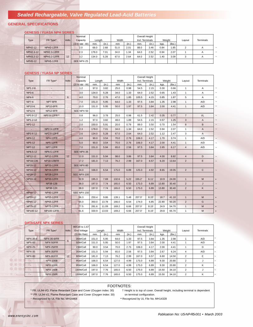
Sealed Rechargeable, Valve Regulated Lead-Acid Batteries
FOOTNOTES:* FR: UL94-VO, Flame Retardant Case and Cover (Oxygen index: 30) † Height is to top of cover. Overall height, including terminal is dependent
** FR: UL94-V2, Flame Retardant Case and Cover (Oxygen index: 30) on terminal configuration.~ Recognized by UL File No. MH16464 • Recognized by UL File No. MH14328
GENERAL SPECIFICATIONS
GENESIS / YUASA NPH SERIESNominal Overall Height
Type FR Type* Volts Capacity Length Width Incl. Terminals Weight Layout Terminals
(10 hr rate - Ah) mm. (in.) mm (in.) mm. (in.) kgs. (lbs.)
NPH2-12 NPH2-12FR 2.0 68.0 2.68 51.0 2.01 88.0 3.46 0.84 1.85 2 A
NPH2.3-12 NPH2.3-12FR 2.3 178.0 7.01 34.0 1.34 64.0 2.52 0.94 2.07 1 A
NPH3.2-12 NPH3.2-12FR 12 3.2 134.0 5.28 67.0 2.64 64.0 2.52 1.40 3.09 3 A
NPH5-12 NPH5-12FR SEE NPX-25
GENESIS / YUASA NP SERIESNominal Overall Height
Type FR Type* Volts Capacity Length Width Incl. Terminals Weight Layout Terminals
(20 hr rate - Ah) mm. (in.) mm (in.) mm. (in.) kgs. (lbs.)
NP1.2-6 - 1.2 97.0 3.82 25.0 0.98 54.5 2.15 0.30 0.66 1 A
NP3-6 - 3.0 134.0 5.28 34.0 1.33 64.0 2.52 0.65 1.43 1 A
NP4-6 - 6 4.0 70.0 2.76 47.0 1.85 105.5 4.15 0.85 1.87 5 A
NP7-6 NP7-6FR 7.0 151.0 5.95 64.0 1.33 97.5 3.84 1.35 2.98 1 A/D
NP10-6 NP10-6FR 10.0 151.0 5.95 50.0 1.97 97.5 3.84 2.00 4.41 1 A/D
NP12-6 NP12-6FR SEE NPX-50
NP0.8-12 NP0.8-12FR** 0.8 96.0 3.78 25.0 0.98 61.5 2.42 0.35 0.77 7 I/L
NP1.2-12 - 1.2 97.0 3.82 48.0 1.89 54.5 2.15 0.57 1.25 3 A
NP2-12 - 2.0 150.0 5.91 20.0 0.79 89.0 3.50 0.70 1.54 8 B
- NP2.3-12FR 2.3 178.0 7.01 34.0 1.34 64.0 2.52 0.94 2.07 1 A
NP2.6-12 NP2.6-12FR 2.6 134.0 5.28 67.0 2.64 64.0 2.52 1.12 2.47 3 A
NP4-12 NP4-12FR 4.0 90.0 3.54 70.0 2.76 106.0 4.17 1.70 3.74 1 A/D
NP5-12 NP5-12FR 5.0 90.0 3.54 70.0 2.76 106.0 4.17 2.00 4.41 1 A/D
NP7-12 NP7-12FR 7.0 151.0 5.94 65.0 2.56 97.5 3.84 2.65 6.17 4 A/D
NP8.5-12 NP8.5-12FR SEE NPX-35
NP12-12 NP12-12FR 12 12.0 151.0 5.94 98.0 3.86 97.5 3.84 4.00 8.82 4 D
NP18-12B NP18-12BFR 17.2 181.0 7.13 76.2 2.99 167.0 6.57 6.20 13.64 2 E
NP20-12 NP20-12FR SEE NPX-80
NP24-12 NP24-12FR 24.0 166.0 6.54 175.0 6.89 125.0 4.92 8.65 19.05 2 C
NP28-12 NP28-12FR SEE NPX-100
NP33-12 NP33-12FR 32.9 195.3 7.69 132.6 5.22 155.2† 6.11† 10.9 24.00 1 M
- NP38-12B 38.0 197.0 7.74 165.0 6.50 175.0 6.89 13.80 30.40 2 J
- NP38-12R 38.0 197.0 7.74 165.0 6.50 175.0 6.89 13.80 30.40 2 K
NP40-12 NP40-12FR SEE NPX-150
NP55-12 NP55-12FR 56.3 250.4 9.86 139.1 5.48 207.0† 8.15† 18.7 41.10 1 M
NP65-12 NP65-12FR 65.0 350.0 13.78 166.0 6.54 174.0 6.85 22.80 50.20 2 G
NP75-12 NP75-12FR 77.5 281.6 11.09 169.2 6.66 207.0† 8.15† 24.9 54.70 1 M
NP100-12 NP100-12FR 91.6 330.9 13.03 169.2 6.66 207.0† 8.15† 29.8 65.70 1 M
~
~
~
~
~
~
•
~
~
•
~
•
•
~
~
~
~
~
~
~
~
~
~
~
~
~
~
~
~
~
~
~
~
~
DATASAFE NPX SERIESW/Cell to 1.67 Overall Height
Type FR Type* Volts End Voltage Length Width Incl. Terminals Weight Layout Terminals
(15 Min Rate) mm. (in.) mm (in.) mm. (in.) kgs. (lbs.)
NPX-35-6 NPX-35-6/FR 35W/Cell 151.0 5.95 64.0 1.33 97.5 3.84 1.35 2.98 1 A/D
NPX-50 NPX-50/FR6
50W/Cell 151.0 5.95 50.0 1.97 97.5 3.84 2.00 4.41 1 A/D
NPX-25 NPX-25/FR 23W/Cell 90.0 3.54 70.0 2.75 106.0 4.17 2.00 4.41 1 D
NPX-35 NPX-35/FR 35W/Cell 151.0 5.94 65.0 2.56 97.5 3.84 2.67 6.24 4 A/D
NPX-80 NPX-80/FR 12 80W/Cell 181.0 7.13 76.2 2.99 167.0 6.57 6.60 14.50 2 E
- NPX-100B 95W/Cell 166.0 6.54 127.0 4.99 175.0 6.89 9.30 20.80 2 J
- NPX-100R 95W/Cell 166.0 6.54 127.0 4.99 175.0 6.89 9.30 20.80 2 K
- NPX-150B 150W/Cell 197.0 7.76 165.0 6.50 175.0 6.89 15.50 34.10 2 J
- NPX-150R 150W/Cell 197.0 7.76 165.0 6.50 175.0 6.89 15.50 34.10 2 K
Publication No: US-NP-RS-001 • March 2003
Range Summary
NP
www.enersysinc.com
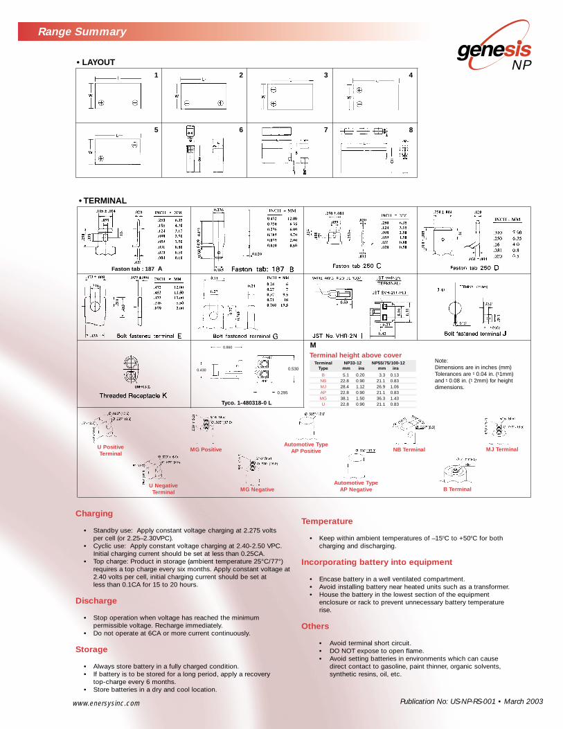
• TERMINAL
• LAYOUT4321
7 865
Faston tab : 187 A
0.860
0.430
0.295
0.530
Tyco. 1-480318-0 L
Charging
• Standby use: Apply constant voltage charging at 2.275 volts per cell (or 2.25–2.30VPC).
• Cyclic use: Apply constant voltage charging at 2.40-2.50 VPC.Initial charging current should be set at less than 0.25CA.
• Top charge: Product in storage (ambient temperature 25°C/77°)requires a top charge every six months. Apply constant voltage at 2.40 volts per cell, initial charging current should be set at less than 0.1CA for 15 to 20 hours.
Discharge
• Stop operation when voltage has reached the minimum permissible voltage. Recharge immediately.
• Do not operate at 6CA or more current continuously.
Storage
• Always store battery in a fully charged condition.• If battery is to be stored for a long period, apply a recovery
top-charge every 6 months.• Store batteries in a dry and cool location.
Temperature
• Keep within ambient temperatures of –150C to +500C for both charging and discharging.
Incorporating battery into equipment
• Encase battery in a well ventilated compartment.• Avoid installing battery near heated units such as a transformer.• House the battery in the lowest section of the equipment
enclosure or rack to prevent unnecessary battery temperature rise.
Others
• Avoid terminal short circuit.• DO NOT expose to open flame.• Avoid setting batteries in environments which can cause
direct contact to gasoline, paint thinner, organic solvents, synthetic resins, oil, etc.
Note:Dimensions are in inches (mm)Tolerances are -+ 0.04 in. (-+1mm) and -+ 0.08 in. (-+ 2mm) for height dimensions.
U PositiveTerminal
MG PositiveAutomotive Type
AP Positive NB Terminal MJ Terminal
U NegativeTerminal MG Negative
Automotive TypeAP Negative B Terminal
Terminal height above coverTerminal NP33-12 NP55/75/100-12
Type mm ins mm ins
B 5.1 0.20 3.3 0.13NB 22.8 0.90 21.1 0.83MJ 28.4 1.12 26.9 1.06AP 22.8 0.90 21.1 0.83MG 38.1 1.50 36.3 1.43U 22.8 0.90 21.1 0.83
M
EnerSys Inc.P.O. Box 14145 Reading, PA 19612-4145USATel:+1-610-208-1991
+1-800-538-3627
EnerSys EMEABrussels, BelgiumTel:+32 (0)2 247 94 47EnerSys AsiaGuangdong, ChinaTel:+86 755 2689 3639
Represented by:
Publ
icat
ion
No:
US-
NP-
RS-0
01 •
Mar
ch 2
003
www.enersysinc.com
Limited Warranty:Each Genesis NP Series battery which is sold is warranted against defects in workmanship and materials for a period of one year from the date of manufacture. Under this warranty, our obligation will be limited to the repair or replacement of the battery. Such repair or replacement will be FOB our warehouse in Santa Fe Springs, California or other designated location that EnerSys Inc. may designate. Such repair or replacement will be made only after our examination determines that said battery is defective in material and/or workmanship. We exempt from any warranty claims any battery which hasbeen subjected to misuse, abuse, alteration, or any battery that may have been repaired or attempts made for repair by other than EnerSys Inc. THIS WARRANTY MADE IN LIEU OF ALL OTHER WARRANTIES WITH RESPECT TO THE PRODUCT COVERED HEREBY AND THERE ARE NO OTHERWARRANTIES, WHETHER EXPRESSED OR IMPLIED, OR MERCHANTABILITY OR OTHERWISE EXCEPT THE WARRANTY EXPRESSLY STATEDHEREIN. THE REMEDY SET FORTH HEREIN SHALL BE THE SOLE EXCLUSIVE REMEDY OF ANY PURCHASER WITH RESPECT TO ANY DEFECTIVEPRODUCT, UNDER NO CIRCUMSTANCES SHALL WE BE LIABLE FOR ANY INJURY, LOSS, DAMAGE, OR EXPENSE SUFFERED OR INCURREDWITH RESPECT TO ANY DEFECTIVE PRODUCT.
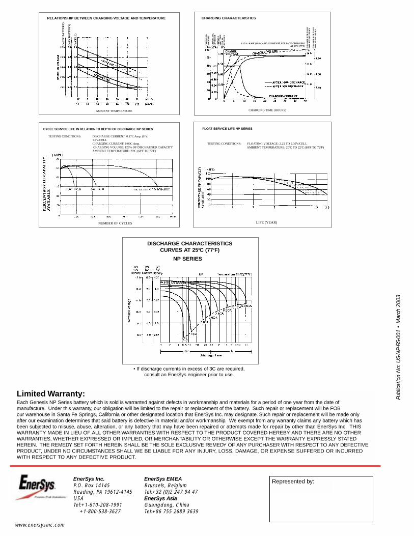
RELATIONSHIP BETWEEN CHARGING VOLTAGE AND TEMPERATURE
AMBIENT TEMPERATURE
CHARGING CHARACTERISTICS
CHARGING TIME (HOURS)
NUMBER OF CYCLES LIFE (YEAR)
FLOAT SERVICE LIFE NP SERIES
TESTING CONDITIONS: FLOATING VOLTAGE: 2.25 TO 2.30V/CELLAMBIENT TEMPERATURE: 200C TO 220C (680F TO 720F)
CYCLE SERVICE LIFE IN RELATION TO DEPTH OF DISCHARGE NP SERIES
TESTING CONDITIONS: DISCHARGE CURRENT: 0.17C Amp. (F.V. 1.7V/CELLCHARGING CURRENT: 0.09C Amp.CHARGING VOLUME: 125% OF DISCHARGED CAPACITY
AMBIENT TEMPERATURE: 200C (680F TO 770F)
DISCHARGE CHARACTERISTICS CURVES AT 250C (770F)
NP SERIES
• If discharge currents in excess of 3C are required, consult an EnerSys engineer prior to use.
0.1CA - 6.90V (13.8V, 4.6V) CONSTANT VOLTAGE CHARGINGAT 25ºC (77ºF)C
HA
RG
ED
V
OL
UM
E
CH
AR
GIN
GC
UR
RE
NT
CH
AR
GE
VO
LT
AG
EF
OR
6V
BA
TT
ER
Y
CH
AR
GE
VO
LT
AG
EF
OR
12V
BA
TT
ER
Y
CH
AR
GE
VO
LT
AG
EF
OR
4V
BA
TT
ER
Y
(V/1
2V B
AT
TE
RY
)
(V/6
V B
AT
TE
RY
)
(V/C
EL
L)


![content.alfred.com · B 4fr C#m 4fr G#m 4fr E 6fr D#sus4 6fr D# q = 121 Synth. Bass arr. for Guitar [B] 2 2 2 2 2 2 2 2 2 2 2 2 2 2 2 2 2 2 2 2 2 2 2 2 2 2 2 2 2 2 2 2 5](https://static.documents.pub/doc/80x56/5e81a9850b29a074de117025/b-4fr-cm-4fr-gm-4fr-e-6fr-dsus4-6fr-d-q-121-synth-bass-arr-for-guitar-b.jpg)


![una grammatica semplificata by Lewis Baker - Home - Esercizi supplementari … · 2019. 11. 30. · (vhufl]l ± 3uhvhqw shuihfw vlpsoh ru 3dvw vlpsoh 6hl pdl vwdwd lq 6fr]ld" +r vwxgldwr](https://static.documents.pub/doc/80x56/60cb631ae072980ad370df36/una-grammatica-semplificata-by-lewis-baker-home-esercizi-supplementari-2019.jpg)


