+ All Categories
Home > Documents > Ranger 400 Manual Door Swing MODERNISATION

Ranger 400 Manual Door Swing MODERNISATION

Date post: 05-Nov-2021
Category:
Upload: others
View: 1 times
Download: 0 times
Share this document with a friend
1
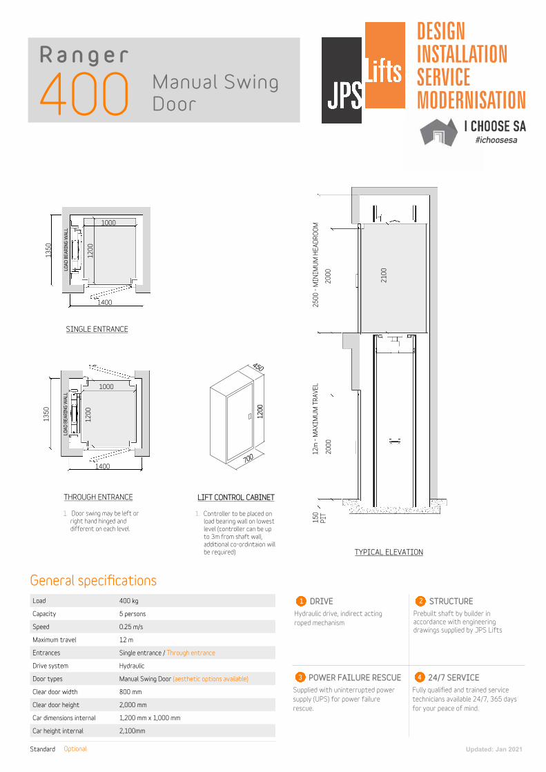
400 Ranger Manual Swing Door DESIGN INSLLION SERVICE MODERNISION I CHOOSE SA #ichoosesa Load Capacity Speed Maximum travel Entrances Drive system Door types Clear door width Clear door height Car dimensions internal Car height internal 400 kg 5 persons 0.25 m/s 12 m Single entrance / Through entrance Hydraulic Manual Swing Door (aesthetic options available) 800 mm 2,000 mm 1,200 mm x 1,000 mm 2,100mm Standard Optional General specifications DRIVE Hydraulic drive, indirect acting roped mechanism 1 STRUCTURE Prebuilt shaft by builder in accordance with engineering drawings supplied by JPS Lifts 2 POWER FAILURE RESCUE Supplied with uninterrupted power supply (UPS) for power failure rescue. 3 24/7 SERVICE Fully qualified and trained service technicians available 24/7, 365 days for your peace of mind. 4 1000 1200 SINGLE ENTRANCE THROUGH ENTRANCE 1350 1400 TYPICAL ELEVATION 2000 2000 2100 2500 - MINIMUM HEADROOM 12m - MAXIMUM TRAVEL 150 PIT 1. Door swing may be left or right hand hinged and different on each level. 1000 1200 1350 1400 LIFT CONTROL CABINET 1. Controller to be placed on load bearing wall on lowest level (controller can be up to 3m from shaft wall, additional co-ordintaion will be required) 700 1200 450 LOAD BEARING WALL LOAD BEARING WALL Updated: Jan 2021
Transcript

400R a n g e r

Manual Swing Door

DESIGN

INSTALLATION

SERVICE

MODERNISATION

I CHOOSE SA #ichoosesa

Load

Capacity

Speed

Maximum travel

Entrances

Drive system

Door types

Clear door width

Clear door height

Car dimensions internal

Car height internal

400 kg

5 persons

0.25 m/s

12 m

Single entrance / Through entrance

Hydraulic

Manual Swing Door (aesthetic options available)

800 mm

2,000 mm

1,200 mm x 1,000 mm

2,100mm

Standard Optional

General specificationsDRIVE

Hydraulic drive, indirect acting roped mechanism

1 STRUCTURE

Prebuilt shaft by builder in accordance with engineering drawings supplied by JPS Lifts

2

POWER FAILURE RESCUE

Supplied with uninterrupted power supply (UPS) for power failure rescue.

3 24/7 SERVICE

Fully qualified and trained service technicians available 24/7, 365 days for your peace of mind.

4

1000

1200

SINGLE ENTRANCE

THROUGH ENTRANCE

1350

1400

TYPICAL ELEVATION

2000

2000

2100

2500

- M

INIM

UM

HEA

DRO

OM

12m

- M

AXI

MU

M T

RAVE

L15

0PI

T1. Door swing may be left or right hand hinged and different on each level.

1000

1200

1350

1400

LIFT CONTROL CABINET

1. Controller to be placed onload bearing wall on lowest level (controller can be up to 3m from shaft wall, additional co-ordintaion will be required)

700

1200

450

LOAD

BEA

RING

WAL

LLO

AD B

EARI

NG W

ALL

Updated: Jan 2021

Recommended