© 2017 Advanced Solutions Nederland B.V. All material presented in this document is protected by copyright under international copyright laws. All specifications are subject to change without notice. The information presented in this document is given in good faith and although every effort has been made to ensure that it is accurate, Advanced Solutions Nederland accepts no liability for any typographical errors.
Page 1
Rapid Design of FIR Filters in the SDR-500 Software Defined Radio Evaluation System using the ASN Filter Designer
Application note (ASN-AN026) October 2017 (Rev 2)
SYNOPSIS
SDR (Software Defined Radio) development includes the implementation of FIR (finite impulse response) filters in DSP
(Digital Signal Processors) or FPGA (Field Programmable Gate Arrays) logic as one of the main components. The design
tools particularly deal with the construction of the filter structure, while for the calculation of the filter coefficients,
additional filter design software is necessary.
This application note shows the simplicity and time advantage of implementing FIR Filters for Huber Signal
Processing’s SDR-500 Software Defined Radio Evaluation System using the ASN Filter Designer.
The following diagram summaries the workflow used within this application note and shows a practical way for
designing an FIR Filter with the ASN Filter Designer, outputting the filter coefficients in Xilinx COE File format, and
importing the resulting COE File into Xilinx ISE for implementation.
Xilinx ISE Xilinx Core
generator
Xilinx FIR
compiler
ASN Filter
Designer
SDR-500 Evaluation system
Figure 1 – Workflow for digital filter design using the ASN Filter Designer for the SDR-500 target system.
© 2017 Advanced Solutions Nederland B.V. All material presented in this document is protected by copyright under international copyright laws. All specifications are subject to change without notice. The information presented in this document is given in good faith and although every effort has been made to ensure that it is accurate, Advanced Solutions Nederland accepts no liability for any typographical errors.
Page 2
INTRODUCTION: SDR-500
The SDR-500 is a Software Defined Radio Evaluation System from Huber Signal Processing, that consists of a hardware
PCB board (shown below) and a comprehensive library of IP blocks.
Figure 2 - SDR-500 PCB (courtesy of Huber Signal Processing).
© 2017 Advanced Solutions Nederland B.V. All material presented in this document is protected by copyright under international copyright laws. All specifications are subject to change without notice. The information presented in this document is given in good faith and although every effort has been made to ensure that it is accurate, Advanced Solutions Nederland accepts no liability for any typographical errors.
Page 3
DETAILED DESCRIPTION OF THE SDR-500
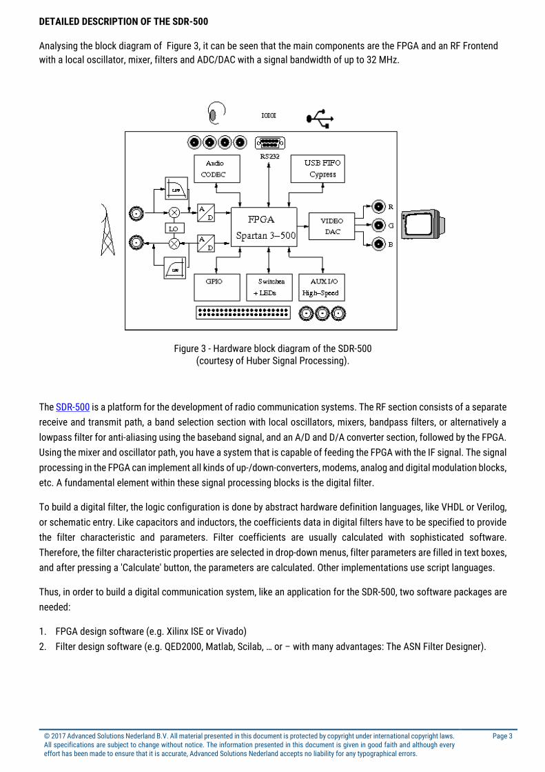
Analysing the block diagram of Figure 3, it can be seen that the main components are the FPGA and an RF Frontend
with a local oscillator, mixer, filters and ADC/DAC with a signal bandwidth of up to 32 MHz.
Figure 3 - Hardware block diagram of the SDR-500 (courtesy of Huber Signal Processing).
The SDR-500 is a platform for the development of radio communication systems. The RF section consists of a separate
receive and transmit path, a band selection section with local oscillators, mixers, bandpass filters, or alternatively a
lowpass filter for anti-aliasing using the baseband signal, and an A/D and D/A converter section, followed by the FPGA.
Using the mixer and oscillator path, you have a system that is capable of feeding the FPGA with the IF signal. The signal
processing in the FPGA can implement all kinds of up-/down-converters, modems, analog and digital modulation blocks,
etc. A fundamental element within these signal processing blocks is the digital filter.
To build a digital filter, the logic configuration is done by abstract hardware definition languages, like VHDL or Verilog,
or schematic entry. Like capacitors and inductors, the coefficients data in digital filters have to be specified to provide
the filter characteristic and parameters. Filter coefficients are usually calculated with sophisticated software.
Therefore, the filter characteristic properties are selected in drop-down menus, filter parameters are filled in text boxes,
and after pressing a 'Calculate' button, the parameters are calculated. Other implementations use script languages.
Thus, in order to build a digital communication system, like an application for the SDR-500, two software packages are
needed:
1. FPGA design software (e.g. Xilinx ISE or Vivado)
2. Filter design software (e.g. QED2000, Matlab, Scilab, … or – with many advantages: The ASN Filter Designer).
© 2017 Advanced Solutions Nederland B.V. All material presented in this document is protected by copyright under international copyright laws. All specifications are subject to change without notice. The information presented in this document is given in good faith and although every effort has been made to ensure that it is accurate, Advanced Solutions Nederland accepts no liability for any typographical errors.
Page 4
1. The ASN Filter Designer
ASN Filter Designer provides engineers with a powerful DSP experimentation platform, allowing for the design,
experimentation and deployment of complex IIR (infinite impulse response) and FIR digital filter designs for a variety of
sensor measurement applications. The tool’s advanced functionality, includes a graphical based real-time filter
designer, multiple filter blocks, various mathematical I/O blocks, live symbolic math scripting and real-time signal
analysis (via a built-in signal analyser). These advantages coupled with automatic documentation and code generation
functionality allow engineers to design and validate a digital filter within minutes rather than hours.
1.1. Designing FIR filters with the ASN Filter Designer
An intuitive real-time graphical user interface allows designers to undertake the design and analysis of FIR filters with
just a few mouse clicks. As seen below, design of a suitable FIR filter based on the desired user specifications is
expedited by virtue of sketching the desired frequency response (lowpass in this case) via the graphical design markers
and allowing the Parks-McClellan algorithm to automatically fill in the necessary technical specifications, such as Filter
Order automatically.
The graphical design marker concept forms the essence of the intuitiveness of the tool, allowing designers to
graphically specify their design specifications and see the true filter frequency response in real-time:
Click and hold the red square with the left mouse button and then drag in any direction to modify the
marker's position. The filter specification table will automatically be updated.
© 2017 Advanced Solutions Nederland B.V. All material presented in this document is protected by copyright under international copyright laws. All specifications are subject to change without notice. The information presented in this document is given in good faith and although every effort has been made to ensure that it is accurate, Advanced Solutions Nederland accepts no liability for any typographical errors.
Page 5
1.2. Algorithm convergence and errors
The Parks-McClellan algorithm is an optimal Chebyshev FIR design method, however the algorithm may not converge
for some specifications. In such cases, increasing the distance between the design marker bands generally helps.
Errors in the root finding algorithm usually lead to undesirable results for high order filter implementations.
As a consequence, the zeros presented in the P-Z chart for higher orders (> 60 or so) should only be
interpreted as an illustration of the true positions. Also, if you are designing a high order FIR filter with a few hundred
taps, it is not recommended to use the P-Z editor for editing the positions of the zeros.
1.3. Quantisation options and Filter Structure
After obtaining the desired frequency response, it is necessary to quantise the filter coefficients for deployment. The
SDR-500 development board’s Q15 coefficient quantisation requirement may be simply specified via the quantisation
tab Q as shown below:
The tool’s inbuilt analytics (shown in the textbox) are intended to help the designer choose the most suitable
quantisation settings. As seen above, the tool has recommended a RFWL (recommended fraction length) of 15bits
(Q15) for the coefficients, which is as required.
© 2017 Advanced Solutions Nederland B.V. All material presented in this document is protected by copyright under international copyright laws. All specifications are subject to change without notice. The information presented in this document is given in good faith and although every effort has been made to ensure that it is accurate, Advanced Solutions Nederland accepts no liability for any typographical errors.
Page 6
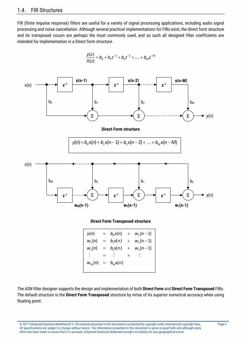
1.4. FIR Structures
FIR (finite impulse response) filters are useful for a variety of signal processing applications, including audio signal
processing and noise cancellation. Although several practical implementations for FIRs exist, the direct form structure
and its transposed cousin are perhaps the most commonly used, and as such all designed filter coefficients are
intended for implementation in a Direct form structure.
MMzbzbzbb
zX
zy ....)(
)( 22
110
Direct Form structure
Direct Form Transposed structure
The ASN filter designer supports the design and implementation of both Direct Form and Direct Form Transposed FIRs.
The default structure is the Direct Form Transposed structure by virtue of its superior numerical accuracy when using
floating point.
z-1
z-1 z-1
b0 b2 b1 bM
x(n)
y(n)
x(n-2) x(n-1) x(n-M)
)()2()1()()( 210 Mnxbnxbnxbnxbny M
x(n))(
)1(x(n))(
)1(x(n))(
)1()()(
322
211
10
MM bnw
nwbnw
nwbnw
nwnxbny
z-1 z-1 z-1
bM b1 b2 b0
x(n)
y(n)
w1(n-1) w2(n-1) wM(n-1)
© 2017 Advanced Solutions Nederland B.V. All material presented in this document is protected by copyright under international copyright laws. All specifications are subject to change without notice. The information presented in this document is given in good faith and although every effort has been made to ensure that it is accurate, Advanced Solutions Nederland accepts no liability for any typographical errors.
Page 7
1.5. Automatic code generation to Vivado
The ASN Filter Designer automatic code generation engine facilitates automatic code generation for the Xilinx FIR
compiler suite (Vivado), as shown below:
Selecting Xilinx FIR Compiler from the listbox, the tool will automatic generate the COE file needed for implementation
in the ISE or Vivado development tool.
© 2017 Advanced Solutions Nederland B.V. All material presented in this document is protected by copyright under international copyright laws. All specifications are subject to change without notice. The information presented in this document is given in good faith and although every effort has been made to ensure that it is accurate, Advanced Solutions Nederland accepts no liability for any typographical errors.
Page 8
2. Configuring FIR Filters in Xilinx ISE
In the standard edition of the SDR-500, a Xilinx Spartan-3 FPGA is used. The design tool that is therefore used is ISE.
Later versions will use FPGAs that are programmed with Vivado. In all cases the workflow is similar, and compatible
with the code generated from the ASN Filter Designer’s automatic code generator.
STEP 1: First, start Xilinx ISE, open your project, or create a new project.
Figure 4 - Xilinx ISE default view with Core Generator selected in the Tools drop-down menu item
The filter design is usually done with the program FIR Compiler.1 In this section, the design of an FIR Filter with the FIR
Compiler is shown. To start it, select the Core Generator in the Tools menu.
1 The FIR Compiler is also used in ISE's successor design tool Xilinx Vivado
© 2017 Advanced Solutions Nederland B.V. All material presented in this document is protected by copyright under international copyright laws. All specifications are subject to change without notice. The information presented in this document is given in good faith and although every effort has been made to ensure that it is accurate, Advanced Solutions Nederland accepts no liability for any typographical errors.
Page 9
STEP 2: Now the Core Generator window opens. On the left-hand side, the IP Catalog is shown.
After generating a new Core Generator project file, search for Digital Signal Processing -> Filters and start the program
FIR Compiler by double-clicking on it.
© 2017 Advanced Solutions Nederland B.V. All material presented in this document is protected by copyright under international copyright laws. All specifications are subject to change without notice. The information presented in this document is given in good faith and although every effort has been made to ensure that it is accurate, Advanced Solutions Nederland accepts no liability for any typographical errors.
Page 10
STEP 3: Now the FIR Compiler program opens in a new window.
The FIR Compiler has several parameters to adjust. At the right side, you can select a Vector (data in the text box above)
or a COE File as source of the filter coefficients.
2.1. What is a COE File ?
A COE File is a simple text file that contains the filter coefficients, as well as a header with some information. The
syntax of the general form for a COE file is described in detail here. It is comprised of comments, a header and a list of
the filter coefficients. A small example is shown here:
;// Arithmetic = 'Fixed Point (Q0.15)';
;// Architecture = 'FIR';
;// Structure = 'Direct Form';
;// Response = 'Lowpass';
;// Method = 'Parks–McClellan';
;// GridSize = 100;
;// Fs = 500.00Hz;
;// Filter Order = 24
;// ** ASN filter Designer Automatic Code Generator **
;// ** Deployment to Xilinx Vivado FIR Compiler Suite **
Section with optional comments
radix=10; Section with keywords for radix values
coefdata=
-14, -37, -16, 118,
290, 205, -394, -1201,
-1175, 757, 4506, 8352,
9990, 8352, 4506, 757,
-1175, -1201, -394, 205,
290, 118, -16, -37,
-14;
Section with coefficient data
© 2017 Advanced Solutions Nederland B.V. All material presented in this document is protected by copyright under international copyright laws. All specifications are subject to change without notice. The information presented in this document is given in good faith and although every effort has been made to ensure that it is accurate, Advanced Solutions Nederland accepts no liability for any typographical errors.
Page 11
STEP 4: Now choose COE File as data input and browse the file you have exported before with the ASN Filter Designer.
On the left side of the FIR Compiler window, you can see the
automatically adjusted Frequency Response plot. It should
be identical to your filter built previously with the ASN Filter
Designer.
If all parameters shown are correct, press the Next button,
adjust all parameters to your needs, and so on. The last
page will show you the summary. Ensure that all
parameters are correct. If so, press the Generate button.
After the generation is finished, you can use your VHDL,
Verilog or Schematic symbol design in your ISE project, as
shown overleaf, and for further use with the SDR-500
Software Defined Radio board.
© 2017 Advanced Solutions Nederland B.V. All material presented in this document is protected by copyright under international copyright laws. All specifications are subject to change without notice. The information presented in this document is given in good faith and although every effort has been made to ensure that it is accurate, Advanced Solutions Nederland accepts no liability for any typographical errors.
Page 12
2.2. The last steps
The FIR filter that we have built as description for the FPGA with its filter coefficients is now ready for being used in
your FPGA project. Build your binary file(s) using the and download to your target FPGA or PROM.
Repeat the filter tuning, FPGA compilation and download until the result fits the requirements.
© 2017 Advanced Solutions Nederland B.V. All material presented in this document is protected by copyright under international copyright laws. All specifications are subject to change without notice. The information presented in this document is given in good faith and although every effort has been made to ensure that it is accurate, Advanced Solutions Nederland accepts no liability for any typographical errors.
Page 13
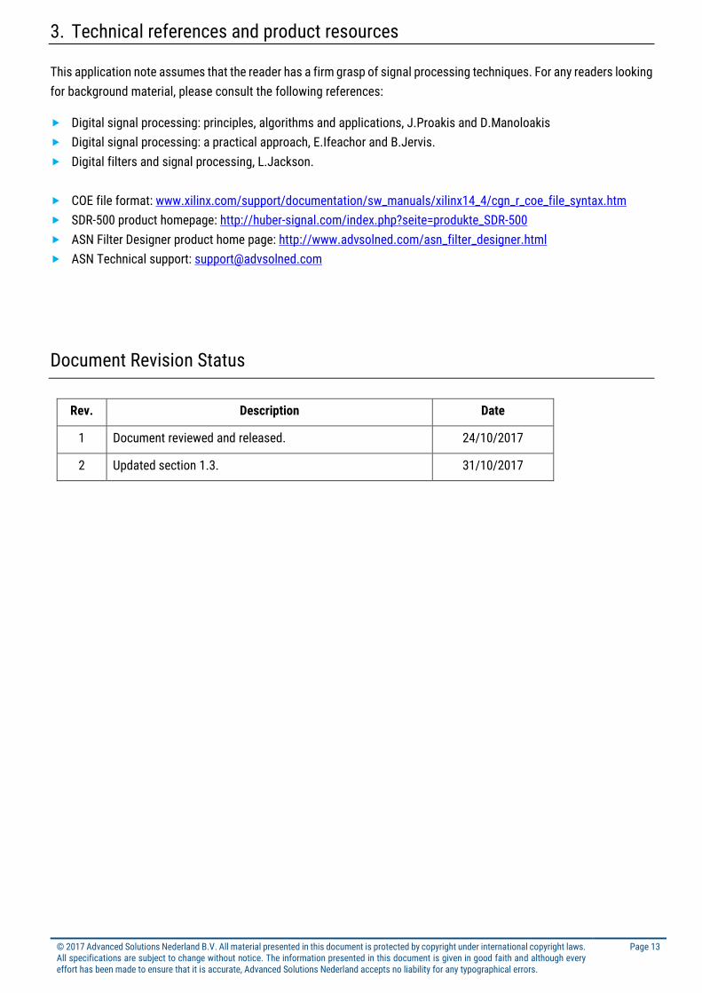
3. Technical references and product resources
This application note assumes that the reader has a firm grasp of signal processing techniques. For any readers looking
for background material, please consult the following references:
Digital signal processing: principles, algorithms and applications, J.Proakis and D.Manoloakis
Digital signal processing: a practical approach, E.Ifeachor and B.Jervis.
Digital filters and signal processing, L.Jackson.
COE file format: www.xilinx.com/support/documentation/sw_manuals/xilinx14_4/cgn_r_coe_file_syntax.htm
SDR-500 product homepage: http://huber-signal.com/index.php?seite=produkte_SDR-500
ASN Filter Designer product home page: http://www.advsolned.com/asn_filter_designer.html
ASN Technical support: [email protected]
Document Revision Status
Rev. Description Date
1 Document reviewed and released. 24/10/2017
2 Updated section 1.3. 31/10/2017