Rapid Integration and Calibration of New Sensors Using the Berkeley Aachen Robotics Toolkit (BART) Jan O. Biermeyer † Todd R. Templeton † Christian Berger ‡ Humberto Gonzalez † Nikhil Naikal † Bernhard Rumpe ‡ S. Shankar Sastry † † Department of Electrical Engineering and Computer Sciences, University of California, Berkeley, CA 94720, U.S.A. phone: +1 (510) 643-9783, fax: +1 (510) 643-2356, email: {janb, ttemplet, hgonzale, nnaikal, sastry}@eecs.berkeley.edu. ‡ Software Engineering, RWTH Aachen, 52074 Aachen, Germany. phone: +49 (241) 80-21301, fax: +49 (241) 80-22218, web: http://se-rwth.de/. Abstract After the three DARPA Grand Challenge contests many groups around the world have continued to actively research and work toward an autonomous vehicle capable of accom- plishing a mission in a given context (e.g. desert, city) while following a set of prescribed rules, but none has been completely successful in uncontrolled environments, a task that many people trivially fulfill every day. We believe that, together with improving the sen- sors used in cars and the artificial intelligence algorithms used to process the information, the community should focus on the systems engineering aspects of the problem, i.e. the limitations of the car (in terms of space, power, or heat dissipation) and the limitations of the software development cycle. This paper explores these issues and our experiences overcoming them. 1 Introduction After the 2007 DARPA Urban Challenge [1], we summarized our ideas in a position paper [2] at AAET 2008. We greatly benefited from the subsequent discussions and interactions at AAET 2008 and 2009. With this paper, we return to AAET 2010 to present our progress, and to invite feedback on our achievements and our proposed future research directions from both academia and industry. We focus on the following accomplishments since our first AAET paper: (i) We have fully actuated and equipped a 2008 Ford Escape Hybrid XGV (Figure 1), which is capable of remote control, assisted driving, and fully autonomous operation; we describe it in detail in Section 2. (ii) We have developed the Berkeley Aachen Robotics Toolkit (BART), which is comprised of Berkeley’s Intelligent Robotics Toolkit (IRT) and Aachen’s Hesperia Software Environment. We describe BART in Section 3, IRT in Section 3.1, and Hesperia in Section 3.2. We hope to soon release BART to the general public under a three-clause BSD license, and we actively support and welcome its use in both academia and industry, including as a royalty-free toolkit for teaching purposes; we also welcome the integration of new sensor drivers and high-level algorithms. [BTB+10] J. Biermeyer, T. Templeton, C. Berger, H. Gonzalez, N. Naikal, B. Rumpe, S. Sastry Rapid Integration and Calibration of New Sensors Using the Berkeley Aachen Robotics Toolkit (BART). In: Proceedings des 11. Braunschweiger Symposiums „Automatisierungssysteme, Assistenzsysteme und eingebettete Systeme für Transportmittel“, ITS Niedersachsen, Braunschweig, 2010. www.se-rwth.de/publications
Transcript
Rapid Integration and Calibration of New SensorsUsing the Berkeley Aachen Robotics Toolkit (BART)
Jan O. Biermeyer† Todd R. Templeton† Christian Berger‡
Humberto Gonzalez† Nikhil Naikal† Bernhard Rumpe‡ S. Shankar Sastry†
†Department of Electrical Engineering and Computer Sciences, University of California, Berkeley, CA 94720, U.S.A.phone: +1 (510) 643-9783, fax: +1 (510) 643-2356, email: {janb, ttemplet, hgonzale, nnaikal, sastry}@eecs.berkeley.edu.
After the three DARPA Grand Challenge contests many groups around the world have
continued to actively research and work toward an autonomous vehicle capable of accom-
plishing a mission in a given context (e.g. desert, city) while following a set of prescribed
rules, but none has been completely successful in uncontrolled environments, a task that
many people trivially fulfill every day. We believe that, together with improving the sen-
sors used in cars and the artificial intelligence algorithms used to process the information,
the community should focus on the systems engineering aspects of the problem, i.e. the
limitations of the car (in terms of space, power, or heat dissipation) and the limitations
of the software development cycle. This paper explores these issues and our experiences
overcoming them.
1 Introduction
After the 2007 DARPA Urban Challenge [1], we summarized our ideas in a position paper[2] at AAET 2008. We greatly benefited from the subsequent discussions and interactions atAAET 2008 and 2009. With this paper, we return to AAET 2010 to present our progress, andto invite feedback on our achievements and our proposed future research directions from bothacademia and industry.
We focus on the following accomplishments since our first AAET paper: (i) We have fullyactuated and equipped a 2008 Ford Escape Hybrid XGV (Figure 1), which is capable of remotecontrol, assisted driving, and fully autonomous operation; we describe it in detail in Section 2.(ii) We have developed the Berkeley Aachen Robotics Toolkit (BART), which is comprised ofBerkeley’s Intelligent Robotics Toolkit (IRT) and Aachen’s Hesperia Software Environment.We describe BART in Section 3, IRT in Section 3.1, and Hesperia in Section 3.2. We hopeto soon release BART to the general public under a three-clause BSD license, and we activelysupport and welcome its use in both academia and industry, including as a royalty-free toolkitfor teaching purposes; we also welcome the integration of new sensor drivers and high-levelalgorithms.
[BTB+10] J. Biermeyer, T. Templeton, C. Berger, H. Gonzalez, N. Naikal, B. Rumpe, S. Sastry Rapid Integration and Calibration of New Sensors Using the Berkeley Aachen Robotics Toolkit (BART). In: Proceedings des 11. Braunschweiger Symposiums „Automatisierungssysteme, Assistenzsysteme und eingebettete Systeme für Transportmittel“, ITS Niedersachsen, Braunschweig, 2010. www.se-rwth.de/publications
Figure 1: Berkeley DRIVE LAB test platform: 2008 Ford Escape Hybrid XGV
To demonstrate the ease-of-use of our hardware and software platform, we show in Section4 the rapid integration of an automotive sensor, the Hella IDIS laser scanner, as well as ourapproach to calibrating it with respect to a camera system.
2 Hardware Platform
In this section, we describe our vehicle along with other potential candidates and actuationstrategies. We also discuss our computing infrastructure and our sensors.
2.1 Vehicle Selection and Actuation
From our experience using an experimental vehicle for the first two DARPA Grand Challenges[3, 4] and a self-actuated vehicle at the DARPA Urban Challenge [5], it was clear that a caractuated by an OEM, or a specialized kit with support from a third-party supplier, would be thebest choices for minimizing actuation time and maximizing reliability and usable test time.
Our main criteria for selecting a vehicle were (i) energy efficiency, (ii) ease of actuation, (iii)
unobstructed manual operation, (iv) agility, (v) comfortable seating for four adults, (vi) spacioustrunk for computing equipment, (vii) low vibrations when engine on, and (viii) California streetlegal.
Examining the success of DARPA Urban Challenge teams without previous autonomous
car infrastructure, the Volkswagen Passat and Tiguan were obvious choices because of VW’sextensive experience actuating vehicles, the fuel efficiency of the turbo diesel injection (TDI)engine, the optimization of the “Darmstadt” steering column for computer-controlled actuation,the available CAN gateway and an electrical outlet in the trunk, and the fast vehicle delivery(only a few weeks). The main drawbacks of a Volkswagen were its relatively high price (par-tially due to the weak dollar) and Berkeley regulations favoring hybrid vehicles.
With the US military as a major potential sponsor, a military Humvee (Hummer) was an-other obvious choice. Other advantages of the Humvee were its performance in rugged terrainand spacious seating for in-car debugging. For automation, we considered the Kairos strap-on autonomy kit from Kairos Autonomy, a Utah-based company; the autonomy kit could beadapted to virtually any vehicle, but was mainly developed on a Humvee. Drawbacks of theHumvee included its large turning radius, which would complicate navigation in tight urbanspaces; vibration that would make high-accuracy sensing more difficult; and the dubious streetlegality of the strap-on autonomy kit, as well as its obstruction of manual operation.
The Ford Escape Hybrid was one of the first X-by-Wire cars on the US market. For ac-tuation, the obvious choice was TORC Technologies’ ByWire XGV solution, which used theexperience of the DARPA Urban Challenge team Victor Tango to manually actuate the brakeand control all other functions via the ECU. Advantages of this vehicle and autonomy solutionincluded the fact that the actuation would not obstruct manual operation of the vehicle, that itsground clearance would allow it to handle occasional grass fields and washed-out dirt roads (ifnot true off-road use), and that electricity could be drawn from the hybrid battery in the trunk.The major downside was that trunk space would be somewhat limited because of the large hy-brid battery; however, we would would still be able to fit two shock-mounted computer racksin the trunk.
After weighing the alternatives, we chose the Ford Escape Hybrid / ByWire XGV solution.To compensate for the fact that the outer hull was made of thin sheet metal to save weight,we contracted with a local automotive shop to reinforce roof attachment points for our sensormounting rack and to install a bull bar on the front to minimize the potential for deformationduring minor obstacle contact during testing. One problem to which we have not found anadequate solution is that the vehicle cannot be used for some types of driver assistance, sincethe steering wheel is actuated using the power steering motor, which has the potential to breaka human arm; we are currently experimenting with top-of-the-line game controllers, such asthe Logitech G25 Racing Wheel, as an alternative for prototyping such systems.
2.2 Computing and Electrical System
One of our first steps was to install two Star Case computer racks (20”x19” 8RU) in the trunk,on shock-absorbing elastomeric isolation mounts. We dedicated one rack to computers, whichwe mounted vertically to minimize the effect of any shock on the hard drives. We dedicated
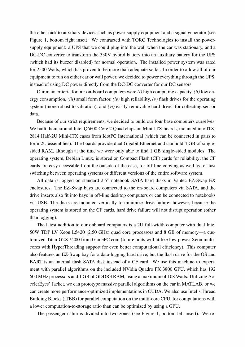
the other rack to auxiliary devices such as power-supply equipment and a signal generator (seeFigure 1, bottom right inset). We contracted with TORC Technologies to install the power-supply equipment: a UPS that we could plug into the wall when the car was stationary, and aDC-DC converter to transform the 330V hybrid battery into an auxiliary battery for the UPS(which had its buzzer disabled) for normal operation. The installed power system was ratedfor 2500 Watts, which has proven to be more than adequate so far. In order to allow all of ourequipment to run on either car or wall power, we decided to power everything through the UPS,instead of using DC power directly from the DC-DC converter for our DC sensors.
Our main criteria for our on-board computers were (i) high computing capacity, (ii) low en-ergy consumption, (iii) small form factor, (iv) high reliability, (v) flash drives for the operatingsystem (more robust to vibration), and (vi) easily-removable hard drives for collecting sensordata.
Because of our strict requirements, we decided to build our four base computers ourselves.We built them around Intel Q6600 Core 2 Quad chips on Mini-ITX boards, mounted into ITS-2814 Half-2U Mini-ITX cases from IdotPC International (which can be connected in pairs toform 2U assemblies). The boards provide dual Gigabit Ethernet and can hold 4 GB of single-sided RAM, although at the time we were only able to find 1 GB single-sided modules. Theoperating system, Debian Linux, is stored on Compact Flash (CF) cards for reliability; the CFcards are easy accessible from the outside of the case, for off-line copying as well as for fastswitching between operating systems or different versions of the entire software system.
All data is logged on standard 2.5” notebook SATA hard disks in Vantec EZ-Swap EXenclosures. The EZ-Swap bays are connected to the on-board computers via SATA, and thedrive inserts also fit into bays in off-line desktop computers or can be connected to notebooksvia USB. The disks are mounted vertically to minimize drive failure; however, because theoperating system is stored on the CF cards, hard drive failure will not disrupt operation (otherthan logging).
The latest addition to our onboard computers is a 2U full-width computer with dual Intel50W TDP LV Xeon L5420 (2.50 GHz) quad core processors and 8 GB of memory—a cus-tomized Titan-G2X / 200 from GamePC.com (future units will utilize low-power Xeon multi-cores with HyperThreading support for even better computational efficiency). This computeralso features an EZ-Swap bay for a data-logging hard drive, but the flash drive for the OS andBART is an internal flash SATA disk instead of a CF card. We use this machine to experi-ment with parallel algorithms on the included NVidia Quadro FX 3800 GPU, which has 192600 MHz processors and 1 GB of GDDR3 RAM, using a maximum of 108 Watts. Utilizing Ac-celerEyes’ Jacket, we can prototype massive parallel algorithms on the car in MATLAB, or wecan create more performance-optimized implementations in CUDA. We also use Intel’s ThreadBuilding Blocks (iTBB) for parallel computation on the multi-core CPU, for computations witha lower computation-to-storage ratio than can be optimized by using a GPU.
The passenger cabin is divided into two zones (see Figure 1, bottom left insert). We re-
placed the stock stereo with a Xenarc MDT-X7000 stereo with a fold-out 7-inch in-dash touch-screen display and front USB access; a Logitech diNovo Edge wireless Bluetooth keyboardwith built-in touchpad is stored in the seat pockets. This allows high-level control of the au-tonomy or assistance system by the front passengers. During development, it also allows thedisplay of debugging info or vehicle state data, in addition to minor debugging. For the back-seat passengers, a Xenarc 1530YR 15.3-inch high-contrast and -brightness display folds downfrom the roof and is easily readable even in bright light, unlike most notebook computers. Allvehicle computers, except for the one connected to the front display, are connected to this dis-play and a keyboard with integrated touchpad via an IOGear GCS78KIT 8-port KVM switch.Additionally, any notebook within the car and any computer within our lab can connect to anycar computer via several Ethernet cables or our in-car wireless router, and our Netgear JGS52424-port Gigabit Ethernet switch.
Throughout our test building, 802.11G wireless Internet access is provided by several D-Link DWL-3200AP access points in wireless distribution system (WDS) mode. By using D-Link ANT24-0700 omni-directional high-gain antennas on the vehicle’s roof, as well as a cus-tom outdoor antenna on the top of our building, wireless access is available virtually anywhereon the test track. Beyond streaming live video data, this connection can be used for remotecontrol, online updates of BART or the Linux OS, or general Internet access. However, for se-curity reasons, the connection can be quickly unplugged, to separate the wired core computersfrom any auxiliary wirelessly-connected computers.
2.3 Environment Perception
As outlined in [2], our main goal is to demonstrate intelligent cars via relatively cheap, com-mercial off-the-shelf sensors. SICK LMS laser scanners are a staple in most autonomous carsfor environment perception, as are our Point Grey Flea2 visible light cameras (mounted in Pelcoenclosures). Thermal IR “night vision” is provided by FLIR ThermoVision A320G cameras.Global position data and inertial measurements are provided by a NovAtel SPAN / ProPak witha Honeywell HG1700 IMU. Our newest sensor addition is a automotive laser scanner, the HellaIDIS, which we discuss further in Section 4. All sensors are mounted on MayTec rails, whichenable both fixed mounts and rapid prototyping / experimentation.
For higher-accuracy comparison data, we use two sensors that are more expensive—we donot envision these sensors as part of any autonomy or driver assistance solution. We use aNovAtel GPS receiver and 900MHz wireless modem for differential GPS, as well as a top-of-the-line NovAtel SPAN (Synchronous Position, Attitude and Navigation) GNSS+INS with atactical grade iMAR IMU-FSAS and magnetic wheel sensors, for more accurate vehicle statedata. Similarly, we utilize a Velodyne HD LIDAR for high-resolution 360 degree environmentperception.
One of the most important features of our sensor setup is that all data is accurately and con-
sistently timestamped by embedded systems before it arrives at the primary vehicle comput-ers. The FireWire cameras are implicitly timestamped by an external trigger from our Agilent33210A signal generator. All other production sensors (this set does not include the Velodyne,which produces an extremely large volume of data) are connected to NetBurner microproces-sor boards by either serial or CAN. These NetBurner boards are also connected to the cameratrigger via a hardware interrupt pin, which they use to maintain an accurate and consistent time.All of the data that passes through the NetBurner boards is timestamped and then sent out to anysubscribed vehicle computer using the Spread Toolkit [6]. Although all sensor data is times-tamped before it reaches the vehicle computers, we also synchronize the vehicle computersusing the Network Time Protocol (NTP). We are considering using a Meinberg GPS synchro-nized NTP server in the future for high-precision time synchronization, as well as real-timeremote control capabilities.
For more details on our sensing and navigation algorithms, see [2].
3 Berkeley Aachen Robotics Toolkit (BART)
The Berkeley Aachen Robotics Toolkit (BART) is the fusion of Berkeley’s Intelligent RoboticsToolkit (IRT) and Aachen’s Hesperia Software Environment. IRT and Hesperia were initiallydeveloped separately, but since they complement each other they have joined forces to create astronger toolkit.
3.1 Intelligent Robotics Toolkit
The Intelligent Robotics Toolkit (IRT) was originally based on a codebase for autonomoushelicopter mapping and landing that had overgrown its flat filesystem layout. We needed toorganize the codebase hierarchically by function, generalize the build system (a static Make-file) to other platforms (we had problems even with other Linux systems) and separate it intodifferent files for different modules, and create a test infrastructure to ensure consistent codequality. The final result can be broken down into two pieces: (i) an advanced infrastructure forcode organization, reuse, building, and testing; and (ii) a set of software modules for roboticsand artificial intelligence that use this infrastructure.
3.1.1 Infrastructure
The IRT infrastructure is centered around a build system that uses Python and SCons [7] forcross-platform portability. The build system reads a file in each directory that contains declar-ative sections about the targets that can be built in that directory, including their (compile-time, run-time, required, and optional) dependencies, which can be anywhere in the reposi-tory. By convention, less-common third-party dependencies are included in the repository’sthird_party directory, and build rules for finding more-common third-party dependencies
are included in the repository’s third_party/external directory. At compile time, wecan specify either a specific target to build or allow the build system to build all targets inthe repository; the build system tells us what targets it is able to build, and the reason whyit is unable to build some specific targets, e.g. a missing dependency. We can also specify across-compilation, e.g. to a specific NetBurner architecture.
We support C/C++, Python (including C/C++ Python extensions), and MATLAB (includingC/C++ MATLAB extensions). Unit tests are built into the IRT infrastructure—we use Google’sgtest C++ unit test library [8] and the built-in Python unittest package. At the end of everybuild, the build system creates a Python script that can be used to run all of the unit tests thatwere compiled, in addition to a shell script or batch file that can be used to set all necessaryenvironment variables.
For cross-platform portability, we rely on our architecture compatibility layer (archcompat),which is a thin wrapper over the system’s API to make it compatible with the standard LinuxAPI. For communication, we use our chardevice library, which provides both cross-platformportability and the ability to seamlessly switch between different communication protocols,such as serial, TCP, UDP, and the Spread Toolkit [6]. For any remaining portability issues, werely on our build system’s ability to create configuration C/C++ header files or Python modulesbased on conditions such as whether certain external libraries are found; these configurationmodules can be used for conditional compilation (C/C++) or run-time adaptation (Python).
To enable further modularity within the project, we use the concept of plugins. Our pluginssystem allows a subclass to register that it implements a specific interface, which allows itslibrary to be dynamically loaded at runtime if the user requests its specific implementation,e.g. the UDP implementation of chardevice or the SICK implementation of the laser scannerdriver. Our plugins library makes it easy for a new base class to support plugins using only afew simple macros.
3.1.2 Modules Overview
In this section we give a brief overview of our most important software modules:
Communicationcdterm terminal program that supports all chardevice protocols (GUI for
chardevice)chardevice transparent and cross-platform communication via for serial, TCP,
UDP, and the Spread Toolkit [6], with data logging and playback
Controlpathplaner implementation of the model predictive controller (MPC) [2]
Mathgraphcluster graph segmentation—implementation of [9]
image object-oriented, multi-type image library based on OpenCV [10]matrix object-oriented matrix library based on LAPACK [11], BLAS [12],
and OpenCV [10]maxflow graph max flow—implementation of [13]
Sensorcamera driver for FireWire camerascommon common sensor driver functionality, including client/serverins driver for several INS devicesladar driver for several LADAR devicesradar driver for several radar devices
Simulationimgrender renderer for sequences of synthetic images, using Blender [14],
from texture and elevation images
Third Partygtest C++ unit-testing framework [8]external contains build rules for finding external librariesopenjaus implementation [15] of the JAUS [16] component and communi-
cation architecture—used to communicate with the TORC XGVsystem
scons cross-platform Python build tool—the base of our build system [7]sicktoolbox a single-threaded version of the Sick LIDAR Matlab/C++ Toolbox
[17]spread Spread Toolkit for multicast communication [6]trio cross-platform stdio implementation [18]
Utilitiesarchcompat architecture compatibility layer to ease portability between Linux,
Unix, NetBurner, and Windowsasyncproc asynchronous process with messaging, locking, and logginglogger file loggermessager inter-thread messagingplugins plugin systemproperties configuration file reader and generic properties interfacerepository base for repositories (such as frame repository in camera module),
checkin/checkout interface with ability to write items to disk
Vehiclexgv joystick demo and JAUS-based XGV simulator
Visioncheckerboarddetector checkerboard detectorelevationmap modular elevation map used for terrain reconstructionrmfpp the Recursive Multi-Frame Planar Parallax (RMFPP) algorithm
[19, 20]
3.2 Hesperia Software Environment
The Hesperia Software Environment is a strictly object-oriented toolkit written in highly portableANSI-C++ to support the development of distributed applications especially in real-time envi-ronments with embedded software. The main focus is on the virtualized software developmentfor sensors- and actuators-based systems by providing an appropriate model of the system’scontext to be used for interactive and unattended system simulations. On the one hand, thesesimulations can be used interactively by the software developer to feed data into the systemunder development (SUD) for evaluation; on the other hand, these simulations can be usedunattendedly to perform an evaluation automatically comparable to the well-known unit tests.
Hesperia was inspired by the experiences from the TU Braunschweig’s contribution “Car-oline” to the 2007 DARPA Urban Challenge. However, it was completely written from scratchextending and exchanging the concepts used for developing software for “Caroline.”
3.2.1 Architectural Design of Hesperia
In Fig. 2, the core design of the Hesperia Software Environment is shown. It consists of twomain libraries namely “libcore” and “libhesperia.” The former library is the encapsulatinglibrary to the operating system or any hardware interfaces. Thus, it ensures platform indepen-dence and interoperability between heterogeneous systems by providing core point-to-pointand broadcast communication concepts as well as thread-safe data storage and filter methods.Currently, this core library is available for Microsoft Windows XP, Microsoft Windows Vista,Microsoft Windows 7, openSUSE, Debian, Ubuntu, FreeBSD, and NetBSD.
The latter library, “libhesperia” is a further layer on top of the previous library. In thislibrary, a domain specific language (DSL) for describing the system’s context is integrated tomodel a system’s context [21] for providing synthetic input data for various layers as describedin the following. Moreover, a ready and easy to use concept for communication between dis-tributed applications called “Client Conference” is provided. This concept allows a fast, exten-sible, scalable, and non-reactive communication for an unlimited number of participants.
On top of this library, the actual system is running. In general, sensors- and actuators-basedautonomous systems can be divided into three major parts: A “Perception Layer” which per-ceives the system’s surroundings by gathering and fusing raw sensor data, a “Decision Layer”which evaluates and interprets the abstract environmental model to derive an abstract action,
Figure 2: Overview of the architectural design of the software framework Hesperia: The frame-work consists of two main parts: “libcore” and “libhesperia.” The former is a library for en-capsulating and abstracting all interfaces to a specific operating system or hardware platformby providing convenient interfaces and wrapper classes; the latter is a library especially forsupporting the development of sensors- and actuators-based autonomous systems by providingconvenient concepts which reuse and further encapsulate the interfaces from “libcore.” More-over, “libhesperia” provides ready and easy to use, thread-safe communication concepts anddata-storage.
and the final “Action Layer” which transforms the abstract action into necessary set values forthe actuators and their controllers. To perform simulations to support the development of such asensors- and actuators-based system, the aforementioned three layers must be closed altogetheror separately into a loop; in the former case synthetic input data must be provided for the “Per-ception Layer” and the system’s reaction must be evaluated at the “Action Layer” to generatenew input data. In the latter case, layer-dependent input data must be provided. Therefore, theso-called “Virtualization Layer” is used to generate the necessary input data by evaluating theDSL which describes the system’s context.
For the running example of this paper, the library “libvehiclecontext” provides some mod-els for the vehicle dynamics. For allowing unattended and automatable system simulations andevaluations, the library “libcontext” is used to abstract from the current real system clock andto control all running applications. Thus, comparable to unit tests, more complex system simu-lations can be described in a machine-processable manner to run and evaluate the SUD nightlyor even more often by integrating into a continuous integration system.
For convenience, further applications are included in the Hesperia Software Environment.The application “supercomponent” is used to provide centralized and thus consistent configu-
ration data using the “Dynamic Module Configuration Protocol” (DMCP) which is inspired bythe well-known DHCP to configure remotely operating applications; furthermore, it supervisesall running applications and tracks their life-cycle. The applications “recorder” and “player” areused to capture non-reactively all communication for later replay. The application “rec2video”is used to render a 3D video from a running system also using the aforementioned DSL whichdescribes the system’s context; for the running example this could be for example an intersec-tion in an urban-like environment with some trees, buildings, and of course moving traffic. Thelast application which is called “monitor” is used to inspect non-reactively a running systemor even a system simulation without modification. Using this application, the data at any stageof the processing chain can be visualized in various representations: Embedded into a 3D con-text, aggregated in charts, or any desired representation by easily extending the plug-in-basedmonitor application.
3.2.2 Sensor Raw Data Provider
As described in the previous section, the “Virtualization Layer” is used to generate differentinput data for the aforementioned layers. While the required input data for the “Action Layer”is rather simple to describe and thus to generate necessary input data for, the “Decision Layer”requires an abstract representation of the perceived system’s surroundings. However, this rep-resentation can be modeled and thus provided for this layer with manageable effort. For theleft-most layer which is dealing with the gathering and processing of the sensors’ raw data, themodel and generation of the required input data is rather complex.
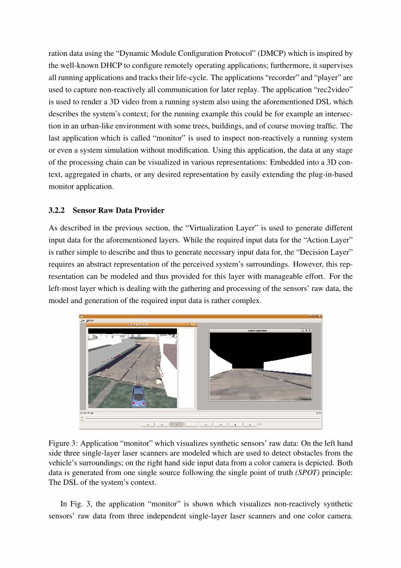
Figure 3: Application “monitor” which visualizes synthetic sensors’ raw data: On the left handside three single-layer laser scanners are modeled which are used to detect obstacles from thevehicle’s surroundings; on the right hand side input data from a color camera is depicted. Bothdata is generated from one single source following the single point of truth (SPOT) principle:The DSL of the system’s context.
In Fig. 3, the application “monitor” is shown which visualizes non-reactively syntheticsensors’ raw data from three independent single-layer laser scanners and one color camera.
For generating the input data for the laser scanners, a GPU-based algorithm is implementedas outlined in [22]. Therefore, the DSL which describes the system’s context is transformedautomatically into a render-able representation by OpenGL at run-time. This render-able rep-resentation is loaded on the GPU and analyzed using the aforementioned algorithm. The resultis transformed into the sensor specific data format and sent to all interested applications. Thesame OpenGL representation of the DSL can be used to provide images to simulate a colorcamera as well.
4 Application: Hella IDIS
The Hella IDIS LIDAR sensor is marketed as a cost-effective infrared distance sensor. It pro-vides the lateral position and width of objects and can be mounted into the radiator grille of acar. It has a range of 3-150 meters, and a field of view of 12 degrees (US model) horizontallyand 3 degrees vertically. While Hella makes a model that allows the sensor to estimate thetrajectories of objects, if it is provided with additional data from the car, we opted for raw dataoutput and fusing the data ourselves.
4.1 Technical Integration
Our IDIS was delivered with mounting brackets, connectors, and instructions for standard carinstallation. For on-car use, a weather-proof US-car connector is needed; however, for benchtesting a simple molex connector will do. We install the sensor on our car’s bull bar for evalu-ation; we will ultimately mount it between the radiator and the plastic grille.
4.2 Software Integration
Integrating the Hella IDIS into IRT requires two steps: (i) create a chardevice driver for a CANinterface, as this is our first CAN-connected sensor, and (ii) create the sensor driver itself.
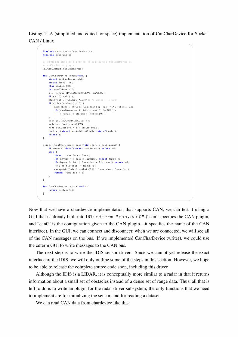
The implementation of CanCharDevice is system-specific; we handle this using conditionalcompilation. Although in practice we will use the NetBurner version of CanCharDevice withthe IDIS, for simplicity we only present here the version for SocketCAN [23] on Linux. Sock-etCAN was originally developed by Volkswagen Research under the name ”Low Level CANFramework” (LLCF); it extends the Berkeley sockets API with a new protocol family, PF CAN,and is supported by the Linux kernel in version 2.6.25 and above. Our CAN-to-USB adaptorsare SocketCAN-compatible. Listing 1 shows a simple implementation of CanCharDevice forSocketCAN / Linux with only basic error handling.
Listing 1: A (simplified and edited for space) implementation of CanCharDevice for Socket-CAN / Linux� �
# i n c l u d e <c h a r d e v i c e / c h a r d e v i c e . h># i n c l u d e <can / can . h>
/ / I m p l e m e n t a t i o n f i l e p o r t i o n o f r e g i s t e r i n g CanCharDevice as/ / a CharDevice p l u g i n .PLUGIN DEFINE ( CanCharDevice )
i n t CanCharDevice : : open ( void ) {s t r u c t s o c k a d d r c a n add r ;s t r u c t i f r e q i f r ;char ∗ t o k e n s [ 2 ] ;i n t numTokens = 0 ;s = : : s o c k e t ( PF CAN , SOCK RAW, CAN RAW) ;i f ( s < 0) e x i t ( 1 ) ;s t r c p y ( i f r . i f r n a m e , "can0" ) ; / / d e f a u l t t o can0i f ( s t r l e n ( o p t i o n s ) > 0) {
numTokens = s t r s p l i t d e s t r o y ( o p t i o n s , ’,’ , t okens , 2 ) ;i f ( ( numTokens == 1) && ( t o k e n s [ 0 ] != NULL) )
s t r c p y ( i f r . i f r n a m e , t o k e n s [ 0 ] ) ;}i o c t l ( s , SIOCGIFINDEX , &i f r ) ;add r . c a n f a m i l y = AF CAN ;add r . c a n i f i n d e x = i f r . i f r i f i n d e x ;b ind ( s , ( s t r u c t s o c k a d d r ∗)&addr , s i z e o f ( add r ) ) ;re turn 1 ;
}
s s i z e t CanCharDevice : : r e a d ( void ∗buf , s i z e t c o u n t ) {i f ( c o u n t < s i z e o f ( s t r u c t c a n f r a m e ) ) re turn −1;e l s e {
s t r u c t : : c a n f r a m e frame ;i n t n b y t e s = : : r e a d ( s , &frame , s i z e o f ( f rame ) ) ;i f ( n b y t e s != 16 | | f rame . l e n + 2 > c o u n t ) re turn −1;∗ ( ( u i n t 1 6 t ∗) buf ) = f rame . i d ;memcpy ( & ( ( ( u i n t 8 t ∗) buf ) [ 2 ] ) , f rame . da t a , f rame . l e n ) ;re turn f rame . l e n + 2 ;
}}
i n t CanCharDevice : : c l o s e ( void ) {re turn : : c l o s e ( s ) ;
}� �Now that we have a chardevice implementation that supports CAN, we can test it using aGUI that is already built into IRT: cdterm "can,can0" (“can” specifies the CAN plugin,and “can0” is the configuration given to the CAN plugin—it specifies the name of the CANinterface). In the GUI, we can connect and disconnect; when we are connected, we will see allof the CAN messages on the bus. If we implemented CanCharDevice::write(), we could usethe cdterm GUI to write messages to the CAN bus.
The next step is to write the IDIS sensor driver. Since we cannot yet release the exactinterface of the IDIS, we will only outline some of the steps in this section. However, we hopeto be able to release the complete source code soon, including this driver.
Although the IDIS is a LIDAR, it is conceptually more similar to a radar in that it returnsinformation about a small set of obstacles instead of a dense set of range data. Thus, all that isleft to do is to write an plugin for the radar driver subsystem; the only functions that we needto implement are for initializing the sensor, and for reading a dataset.
We can read CAN data from chardevice like this:
Listing 2: Reading CAN data using chardevice� �# i n c l u d e <c h a r d e v i c e / c h a r d e v i c e . h>
u i n t 8 t buf [ 1 8 ] ;/ / f a l s e means do n o t w a i t f o r d a t a when c a l l r e a d ( )CharDevice ∗cd = new CharDeviceWrapper ("can,can0" , f a l s e ) ;/ / r e a d any a v a i l a b l e CAN messagei n t n = cd−>r e a d ( buf , 1 8 ) ;i f ( n > 2) {
/ / p r i n t message i n f o ( f i r s t 2 b y t e s a r e message ID )p r i n t f ("id = %hx (%d bytes)\n" , ∗ ( ( u i n t 1 6 t ∗) buf ) , n − 2 ) ;
}/ / when f i n i s h e d , c l o s e c h a r d e v i c ed e l e t e cd ;� �
In HellaRadar::init(), we open the chardevice. In HellaRadar::read() we call the non-blockingchardevice read() method until no CAN message is returned; if a returned CAN message has anID of interest, we extract the relevent information and continue reading CAN messages—wealways return the most recent information available from the sensor.
Now that we have a Hella plugin for the radar subsystem, we can use it like any other radardriver—we can, for example, run the driver in server mode on a NetBurner board, which willtimestamp the data (using a clock maintained from its external trigger signal) and forward itover Ethernet to any vehicle computer that is running a radar driver in client mode that hasconnected to that NetBurner’s radar server (using e.g. the Spread Toolkit).
4.3 Calibration
In order to effectively fuse data from a camera, a Hella IDIS, and a SICK LMS laser scanner,we must determine the rigid body transformation between each pair of sensors. We choose thefocal point of the camera as the origin of the local coordinate system; we must then determinethe extrinsic calibration of the two laser scanners with respect to the camera. Once we have de-termined these transformations, the 3D coordinates from each laser scanner can be transformedto the camera’s coordinates and back-projected onto the camera images for further processing.
In order to determine the 3D vector (through the camera focal point) on which the pointrepresented by a given pixel is constrained to lie, we must obtain the intrinsic calibration of thecamera. We determine these internal parameters of the camera by using the Caltech cameracalibration toolbox [24].
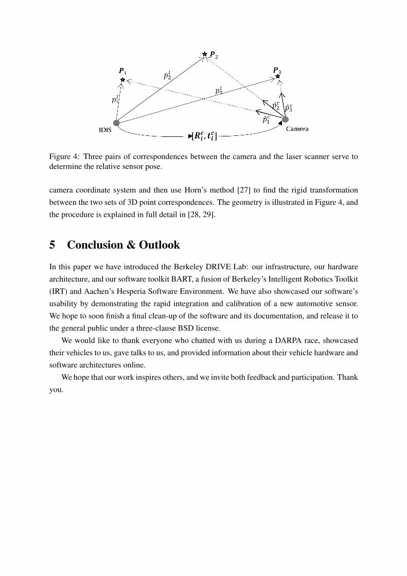
We compute the extrinsic calibration between the camera and a given laser scanner onlyonce, as the sensors are rigidly mounted relative to each other. We perform this calibration usingat least three points in 3D space that we can identify in both sensors—the laser scanner (eitherthe IDIS or the SICK) measures the 3D location of the point in its coordinate system directly,and we can convert the vector through the camera pixel to which the point is projected into a3D coordinate in the camera’s coordinate system by using space resection. Within a RANSAC[25] framework, we use the 3-point algorithm [26] to determine the depth of the points in the
Figure 4: Three pairs of correspondences between the camera and the laser scanner serve todetermine the relative sensor pose.
camera coordinate system and then use Horn’s method [27] to find the rigid transformationbetween the two sets of 3D point correspondences. The geometry is illustrated in Figure 4, andthe procedure is explained in full detail in [28, 29].
5 Conclusion & Outlook
In this paper we have introduced the Berkeley DRIVE Lab: our infrastructure, our hardwarearchitecture, and our software toolkit BART, a fusion of Berkeley’s Intelligent Robotics Toolkit(IRT) and Aachen’s Hesperia Software Environment. We have also showcased our software’susability by demonstrating the rapid integration and calibration of a new automotive sensor.We hope to soon finish a final clean-up of the software and its documentation, and release it tothe general public under a three-clause BSD license.
We would like to thank everyone who chatted with us during a DARPA race, showcasedtheir vehicles to us, gave talks to us, and provided information about their vehicle hardware andsoftware architectures online.
We hope that our work inspires others, and we invite both feedback and participation. Thankyou.
References[1] “DARPA Grand Challenge home page,” Online: http://www.darpa.mil/grandchallenge/index.asp, down-
loaded 10. January 2008.
[2] H. Gonzalez, E. I. Grtli, T. Templeton, J. O. Biermeyer, J. Sprinkle, and S. S. Sastry, “Transitioning controland sensing technologies from fully-autonomous driving to driver assistance systems,” in Proceedings ofthe Symposium on Automation, Assistence, and Embedded Real Time Platforms for Transportation 2007(AAET07), Braunschweig, Germany, 2007.
[3] “Team CyberRider, DARPA Grand Challenge I, Technical Report,” Online: http://www.darpa.mil/grandchallenge04/TeamTechPapers/TeamCyberRiderFinalTP.pdf, 2004.
[4] “Team CyberRider, DARPA Grand Challenge II, Technical Report,” Online: http://www.darpa.mil/grandchallenge05/techpapers/cyberrider.pdf, 2005.
[5] B. Upcroft, M. Moser, A. Makarenko, D. Johnson, A. Donikian, A. Alempijevic, R. Fitch, W. Uther,E. I. Grtli, J. Biermeyer, H. Gonzalez, T. Templeton, V. P. srini, and J. Sprinkle, “DARPA UrbanChallenge Technical Paper: Sydney-Berkeley Driving Team,” University of Sydney; University ofTechnology, Sydney; University of California, Berkeley, Tech. Rep., June 2007. [Online]. Available:http://chess.eecs.berkeley.edu/pubs/379.html
[6] “The Spread Toolkit,” Website: http://www.spread.org/.
[7] “SCons,” Website: http://www.scons.org/.
[8] “Google C++ Testing Framework,” Website: http://code.google.com/p/googletest/.
[9] G. W. Flake, R. E. Tarjan, and K. Tsioutsiouliklis, “Graph clustering and minimum cut trees,” InternetMathematics, vol. 1, no. 4, pp. 385–408, 2003.
[10] G. Bradski, “Programmer’s tool chest: The OpenCV library,” Dr. Dobbs Journal, November 2000.
[11] E. Anderson, Z. Bai, C. Bischof, S. Blackford, J. Demmel, J. Dongarra, J. D. Croz, A. Greenbaum, S. Ham-marling, A. McKenney, and D. Sorensen, LAPACK Users’ Guide, 3rd ed. Philadelphia, PA: Society forIndustrial and Applied Mathematics, 1999.
[12] C. L. Lawson, R. J. Hanson, D. Kincaid, and F. T. Krogh, “Basic Linear Algebra Subprograms for FOR-TRAN usage,” ACM Trans. Math. Soft., vol. 5, pp. 308–323, 1979.
[13] Y. Boykov and V. Kolmogorov, “An experimental comparison of min-cut/max-flow algorithms for energyminimization in vision,” IEEE Trans. Pattern Anal. Mach. Intell., vol. 26, no. 9, pp. 1124–1137, 2004.
[14] B. Foundation, “Blender: the free open source 3d content creation suite,” 2008, version 2.48a. Availablefrom http://www.blender.org.
[17] “The Sick LIDAR Matlab/C++ Toolbox,” Website: http://sicktoolbox.sourceforge.net/.
[18] “Trio - portable and extendable printf and string functions,” Website: http://daniel.haxx.se/projects/trio/.
[19] T. Templeton, “Accurate real-time reconstruction of distant scenes using computer vision: Therecursive multi-frame planar parallax algorithm,” Ph.D. dissertation, EECS Department, University ofCalifornia, Berkeley, Dec 2009. [Online]. Available: http://www.eecs.berkeley.edu/Pubs/TechRpts/2009/EECS-2009-180.html
[20] C. Geyer, T. Templeton, M. Meingast, and S. Shankar Sastry, “The recursive multi-frame planar parallaxalgorithm,” in 3DPVT ’06: Proceedings of the Third International Symposium on 3D Data Processing,Visualization, and Transmission (3DPVT’06). Washington, DC, USA: IEEE Computer Society, 2006, pp.17–24.
[21] C. Berger and B. Rumpe, “Hesperia: Framework zur Szenario-gestutzten Modellierung und EntwicklungSensor-basierter Systeme,” in Proceedings INFORMATIK 2009, S. Fischer, E. Maehle, and R. Reischuk,Eds., vol. 154. GI-Edition Lecture Notes in Informatics (LNI), September 2009, pp. 328,2668–2680.
[22] ——, “Nutzung von projektiven Texturen auf einer GPU zur Distanzmessung fur automotive Sensorsimu-lationen,” in AAET 2009 – Automatisierungssysteme, Assistenzsysteme und eingebettete Systeme fur Trans-portmittel, Gesamtzentrum fur Verkehr Braunschweig e.V., Ed., vol. 10, February 2009, pp. 319–329.
[24] “Camera Calibration Toolbox for Matlab,” Website: http://www.vision.caltech.edu/bouguetj/calib doc.
[25] M. A. Fischler and R. C. Bolles, “Random sample consensus: a paradigm for model fitting with applicationsto image analysis and automated cartography,” Commun. ACM, vol. 24, no. 6, pp. 381–395, 1981.
[26] R. M. Haralick, C.-N. Lee, K. Ottenberg, and M. Nolle, “Review and analysis of solutions of the three pointperspective pose estimation problem,” Int. J. Comput. Vision, vol. 13, no. 3, pp. 331–356, 1994.
[27] B. K. P. Horn, “Closed-form solution of absolute orientation using unit quaternions,” Journal of the OpticalSociety of America. A, vol. 4, no. 4, pp. 629–642, Apr 1987.
[28] N. Naikal, A. Zakhor, and J. Kua, “Image augmented laser scan matching for indoor localization,” EECSDepartment, University of California, Berkeley, Tech. Rep. UCB/EECS-2009-35, Mar 2009. [Online].Available: http://www.eecs.berkeley.edu/Pubs/TechRpts/2009/EECS-2009-35.html
[29] N. Naikal, J. Kua, G. Chen, and A. Zakhor, “Image augmented laser scan matching for indoor dead reck-oning,” in Intelligent Robots and Systems, 2009. IROS 2009. IEEE/RSJ International Conference on, Oct.2009, pp. 4134–4141.