75
1 Professor Chris R. Chatwin Department of Engineering and Design University of Sussex Rapid Prototyping, Tooling and Time Compression by
| Date post: | 06-Oct-2018 |
| Category: |
Documents |
| Upload: | vuongquynh |
| View: | 214 times |
| Download: | 0 times |

1
Professor Chris R ChatwinDepartment of Engineering and Design
University of Sussex
Rapid Prototyping
Tooling and
Time Compressionby
2
What is Concurrent Engineering
Computer Aided
Design (CAD ECAD)
Engineering (CAE)
Computer Aided
Manufacture (CAM)
Process Planning (CAPP)
Computer Integrated
Manufacture (CIM)
Increasingly not a single
organisation but a supply-chain
facilitated by the
Internet and e-commerce
Design amp
Prototyping
Design Plant
amp Processes
Control of
Operations
RESEARCH
RampD
Definition of product need
Marketing information
Conceptual design and evaluation
Research Product Champions
Packaging marketing and
sales literature
Product Supply (JIT)
Material specification process and equipment
selection safety review environmental impact
Pilot production
Design Material Spec Design analysis
codesstandards review physical and analytical
models
Prototype production testing amp evaluation
Production drawings
Instruction manuals
Production
Inspection and quality assurance
P
R
O
D
U
C
T
C
H
A
M
P
I
O
N
S
3
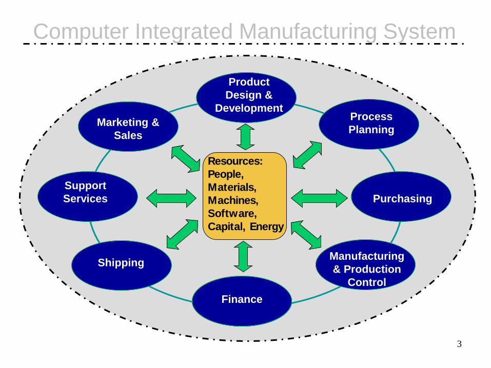
Computer Integrated Manufacturing System
Product
Design amp
Development
Support
Services Purchasing
Shipping
Process
PlanningMarketing amp
Sales
Scotland
OfficeFinance
Manufacturing
amp Production
Control
Resources
People
Materials
Machines
Software
Capital Energy
5
COMPUTER
AIDED DESIGN
(CAD)
ProEngineer
CREO
ECAD
Solid Works
AutoCAD
CADfix
CADfix
IGESDXF
IGESDXF
CAM POST-
PROCESSORS
APS Licom
PEPS
MAGICS
PROTOTYPE
MANUFACTURE
amp TEST
CNC Machining
Laser Machining
Wire EDM
Rapid
Prototyping
Ansys FE
Fluent CFD
MatlabSimulink
System Identification
Signal Processing
Image Processing
Neural Networks Fuzzy
Logic Control Toolbox
Wavelets
ANALYSIS
Creative Product
Design
CADCAE amp CAM
Design Revision Data
6
Courtesy of Ricardo CARP project
7
Technologies Enabling Product
Innovation - Summary
bull Rapid Prototyping - manufacture by layering processes
- Stereolithography
- Selective Laser Sintering (SLS)
- Direct Metal Laser Sintering (DMLS)
- Laminated Object Manufacture (LOM)
- Solid Ground Curing
- 3D Printing
8
What are we trying to achieve
12
Scanning Beam Stereolithography3D Systems SLA
3500 Series
Schematic illustration of the stereolithography process
httpswwwyoutubecomwatchv=_9m5gEtow88 SLA
14
3D Systems Scanning Beam
Stereolithography System
SLA 7000 Series - Dual spot laser
technology gives greater speed
iPro 8000 SLA Printer ndash 650x750x550mm
15
STL Interface
16
STL triangle format
17
Slices from STL Model
18
Data Flow
Generate 3D
CAD model
of object
Generate vector
scanning data to
control the beam
scanning mirrors or
inkjet head the Z axis
and machine process
control instructions
Generate STL
file on CAD
system
Generate support
structures if required
and object level slice
data on target machine
19
Rapid PrototypingSLA 250
Daewoo manifold Logitech - From quote to
working prototype in 7 days
- 3D Systems
Magnetic Resonance Imaging
3D Model
SLA Model
Courtesy of Ricardo
Stereolithography
20
SLA250 Stereolithography
21
Products Using 3D Systems SLA Machine
Texas Instruments -
New shell casing ndash 20 off
$450000 saving on tooling
Johnson Controls for
Coca-Cola - 11 hours
build time 1 week design
Electrolux - Vacuum Cleaner
50 lead time reduction
Black amp Decker - Shrub Trimmer
100 days 30 functioning prototypes
Oldsmobile Aurora ndash 500 ABS parts
9 weeks to 4 weeks - TC 50 Bose Corp
Rover - Injection manifold for new
engine - 90 lead time reduction
16 weeks to 39hrs pound22000 to pound1200
httpswwwyoutubecomwatchv=4y-m1URlh00
Coffeemaker prototypes produced through MultiJetmodeling and final product (at right)Source Courtesy Alessi Corporation and 3D Systems Inc
httpswwwyoutubecomwatchv=apm5Gn2s_-M
23
SLS system1 Spread a layer of powdered
material As the process begins a
precision roller mechanism
automatically spreads a thin layer of
powdered SLS material across the
build platform
2 Sinter a cross-section of the CAD
file Using data from the STL file a
CO2 laser selectively draws a cross
section of the object on the layer of
powder As the laser draws the cross
section it selectively sinters (heats
and fuses) the powder creating a solid
mass that represents one cross
section of the partSinterstation 2500plus
1) More material choices plastic
elastomer metal or ceramic
2) More application options
functional prototypes tooling
patternsmdasheven final parts
3) Build chamber dimensions
(W) 381 mm x (D) 330 mm x (H)
457 mm
Schematic illustration of the selective-laser-sintering process
Source After C Deckard and PF McClure
httpswwwyoutubecomwatchv=9E5MfBAV_tA SLS
25
SLS - Materials
Functional Plastic Prototypes - Create visual models
functional prototypes durable patternsmdasheven plastic
parts for final use DuraForm Polyamide and
DuraForm Glass Filled
Durable Elastomer Prototypes- Produce flexible
rubber-like prototypes and parts SOMOS 201
Casting Patterns Cores and Molds - Quickly
generate investment casting patterns or sand casting
cores and molds CastForm Polystyrene SandForm
Zr SandForm Si
26
SLS Material DuraForm PAtrade - Plastic
Summary
NASA used its in-house Sinterstationreg system
and DuraForm PAtrade to quickly produce a
science cup a tray-like fixture that holds a
variety of instruments wiring and batteries
within a hockey puck-sized self-contained
spacecraft called the Free Flying
Magnetometer (FFM)
The parts generated on the Sinterstation cost
only 300 US $ to produce compared to the
3000 to 5000 US $ it would have taken to
fabricate the parts using traditional machining
methods in aluminium steel or titanium
27
SLS Material SOMOS 201 - Elastomer
Summary
Reeboks Golf Division was in the early stages of
developing a new spikeless golf shoe sole design
and needed a fast cost-effective way to create a
flexible testable prototype Using traditional
prototyping methods (standard tooling and
injection moulding) would have taken 30 to 60 days
and cost Reebok $3500 to $4000 per prototype
Reebok took another approach and prototyped the
new sole design on its in-house Sinterstation
system using SOMOSreg 201 The process took
just seven hours and about $250 worth of
SOMOS 201 The prototype soles were affixed
to a pair of golf shoes and worn by an experienced
golfer for two rounds of golf
Duraform Flex Plastic
Above Radiator hose prototype withstands bending without permanent
damage or deformation (shown without infiltrant)
29
SLS Material - Sandform
Summary
When Woodward Governor Company (WGC) needed
a casting of a new aircraft fuel control system for a
gas turbine engine it faced a formidable challenge
finding a process that could produce a large complex
casting within a very tight time frame
Conventional tooling would have typically required 35
weeks just to generate the tools Then it would have
taken another 12 weeks to get the first casting
These times were cut in half It took just two months to
get the sand cores Whats more the cost was only 20
of the cost of conventional tooling
30
Direct Metal Laser-Sintering (DMLS)
EOSINT M 280 builds metal parts using Direct Metal Laser-Sintering (DMLS)
31
Sinteringhttpwwwyoutubecomwatchv=VImKhUD-8hk
DMLS Direct Metal Laser Sintering process in action utilizing EOS GmbH platform the
M280 This technology sinters layers of fine metal alloys utilizing a 100 watt laser to
additively manufacture real fully dense metal parts
32
How does it work
33
Two small LED
polycarbonate
light guide
moulded parts
EGi PAKTO
Completed
injection mould
Sintered tool
insert
What can you do with the EOSINT
M 280
Production of a
joystick for a
construction
vehicle Moulded
components amp
assembled joystick
FIT GmbH
Project took 6
days from start to
finish
Injection Mould
(core side) for two
components
Four completed
injection moulding
tools
5000 sets (14 parts
per set) moulded
in six weeks best
quote 16 weeks
34
How Does it Perform
bull Laser Type Yb-fibre laser 200 W or 400W
bull Layer Thickness20 - 60 microm
bull Effective building volume (including building platform)250mm x 250mm x 325mm
bull Building speed (material-dependent) 2 - 20 mm3s
bull Scan speed up to 70 ms
bull Variable focus diameter100 - 500 microm
35
What Materials are available for
EOSINT M 280 systems
bull DirectMetal 20
ndash Bronze-based mixture Injection moulding tooling
functional prototypes
bull EOS MaragingSteel MS1
ndash 18 Mar 300 12709 Injection Moulding series tooling
engineering parts
bull EOS StainlessSteel GP1
ndash Stainless steel 17-4 14542 Functional prototypes
and series parts engineering and medical
36
What Materials are available for
EOSINT M 280 systems
bull EOS StainlessSteel PH1
ndash Hardenable Stainless steel Functional prototypes and
series parts engineering and medical
bull EOS CobaltChrome MP1
ndash CoCrMo superalloy Prototypes and series parts
engineering medical dental
bull EOS CobaltChrome SP1
ndash CoCrMo superalloy Dental restorations (series
production)
37
What Materials are available for
EOSINT M 280 systems
bull EOS Titanium Ti64
ndash Ti6Al4V light alloy Prototypes and series
parts aerospace motor sport etc
bull EOS Titanium TiCP
ndash Pure titanium Functional prototypes and
series parts medical dental
bull EOS Aluminium AlSi10Mg
ndash - Light Metal for Motorsports and Aerospace
Interior Applications
What Materials are available
for EOSINT M 280 systems
bull EOS Aluminium AlSi10Mg200 degC
ndash Light Metal for Motorsports and Aerospace
Interior Applications
bull EOS NickelAlloy IN625
ndash Nickel-Chromium Alloy for Aerospace
Motorsports and Industry
bull EOS NickelAlloy HX
ndash Nickel-Alloy for Aerospace and Industry
38
39
Medical Applications
Knee implant in EOS CobaltChrome MP1
(Source EOS)
Medical devices in EOS StainlessSteel 17-4
(Source PEP DePuy)
Components for a sawing guide for big toe joint in DirectMetal 20 (Built on an EOS M250Xtended)
(Source PEPDePuy)
40
Bed of Aerospace parts built
using DMLS
41
Formula 1 amp Aerospace
Engine exhausts in Cobalt
Chrome (EOS CC MP1)
Propeller prototype for wind tunnel testing
in Bronze (DirectMetal EOS DM20)
Turbine blade in Cobalt
Chrome (EOS CC MP1)
Examples of Aerospace Parts built on 3Ts EOS M270 machines in Cobalt Chrome
httpwwwyoutubecomwatchv=1CizD2YLTGgampfeatu
re=related
42
43
44
45
Tooling Inserts
Prototype tooling Bronze DM20
Low volume Injection Moulding
Die casting tool (Maraging Steel)
Die cast car safety belt winder
1500 aluminium parts produced in
good quality more possible
with coating
httpwwwyoutubecomwatchv=88BPmL8cGAoampfeatu
re=related
Laser Deposition Technology (LDT)
46
httpswwwyoutubecomwatchv=d2foaRi4nxM
Trumpf metal laser deposition welding
47httpswwwyoutubecomwatchv=Ao319dj6kiM
48
Laminated Object Manufacture ndash
Helisys ndash Cubic Technologies
49
50
Laminated Object Manufacture
51
Laminated Object Manufacture
Silicon Rubber Moulding ndash Urethane or epoxy
cast plastic parts
Spray Metal Moulds for prototype injection moulding
52
53
Solid Ground Curing - Cubital
SGC 5600 ndash Build Envelope 500x350x500 mm ndash resolution 01 mm
54
55
MIT Alpha Machine ndash 3D Printing
Schematic illustration of the three-dimensional-printing process
Source After E Sachs and M Cima
httpswwwyoutubecomwatchv=7QP73uTJApw
57
Materials for Z Corporationrsquos
Machines now 3D systems
zp14 powder zp100 powder
Composition starchcellulose plaster
Layer Thickness 0004- 001 inches 0003 - 0004 inches
Part Strength 4 MPa 10MPa
Speed
(approx depending on part size) 1 vertical inch per hour 05 vertical inches per hour
Ability to Reuse Unprinted Powder yes yes
58
The machine spreads a layer of powder from the feed box to cover the surface of the build piston
The Z402 System then prints binder solution onto the loose powder forming the first cross-section
Where the binder is printed the powder is glued together
The remaining powder remains loose and supports the layers that will be printed above
When the cross-section is complete the build piston is lowered slightly a new layer of powder is spread over its surface and the process is repeated
The part grows layer by layer in the build piston until the part is complete completely surrounded and covered by loose powder
Finally the build piston is raised and the loose powder is vacuumed away revealing the complete part
Ztrade402 3D PRINTERBuild Volume 8 x 10 x 8
(203 x 254 x 203 mm)
Principle of Operation
59
Z Corporation 3D Colour
Printing
Ztrade402C 3D COLOR PRINTER
Build Speed Colour Mode 033-066 vertical inches (8-16 millimeters) per hour at 0007 layer
Build Volume 6 x 6 x 6 (150 x 150 x 150 mm)files to us to determine suitabilityLayer Thickness User selectable at the time of printing 0003-0010(076-254 mm)
Materials The Z402C System requires zbtrade7 binder While both starch-based powder and plaster-based powder may be used the plaster-based powder produces colours that are more brilliant Colour is applied to the surface of the parts to a uniform depth of approximately 008 inches or 2 mm
Equipment Dimensions 29 x 39 x 42(74 x 99 x 107 cm)
60
Sussex Machine
61
Parts Created
62
Flow amp Thermal Analysis
The computational steps in producing a stereolithography(STL) file
(a) CAD Three-dimensional description of part
(b) The part is divided into slices only 1 in 10 is shown
(c) Support material is planned
(d) A set of tool directions is determined to manufacture each slice Also shown is the extruder path at section AndashA from (c) for a fused-deposition modeling operation
(a) Schematic illustration of the fused-deposition modeling process (b) The FDM 900mc a fused-deposition-modeling machine Source Courtesy of Stratasys Inc
(a) A part with a protruding section that requires support material (b) through (e) Common support structures used in rapid-prototyping machines The gray areas are support materialSource Reused with permission from Society of Manufacturing Engineers
httpswwwyoutubecomwatchv=ik39_sv-wgQ FDM
Examples of low-cost rapid-prototyping systems based on fused-deposition modeling (a) The MakerBotreg Replicatorreg 2 Desktop 3D printer based on fused-deposition modeling and open-source software with a build volume of up to 110 mm times 110 mm times 120 mm using either ABS or PLA (polylactic acid) polymers and (b) the Cube with a build space of up to 140mm times 140 mm times 140 mmSource (a) Courtesy of MakerBot Inc (b) Courtesy of 3D systems
Three-dimensional printing using (a) part-build (b) sinter and (c) infiltration steps to produce metal parts Source Courtesy of The
ExOne Company
httpswwwyoutubecomwatchv=i6Px6RSL9Ac
Rapid-prototyped versions of user-defined characters or avatars produced from geometric descriptions within popular websites or games (a) Second Life avatar as appears on a computer screen (left) and after printing (right) and (b) an avatar known as ldquoWrekerrdquo from World of WarcraftSource (a) Courtesy of Z Corporation (b) Courtesy of Figure Prints and Fabjectory Inc
A fitting for a helicopter fuselage (a)CAD representation with added dimensions (b) Dies produced by three-dimensional printing (c) Final forged workpieceSource (a) Courtesy of The ExOne Company (b) and (c) Courtesy of Kennametal Extrude Hone Corporation
Manufacturing steps for investment casting with rapid-prototyped wax parts as blanks this method uses a flask for the investment but a shell method also can be usedSource Courtesy of 3D Systems Inc
Production of tooling for injection molding by the sprayed-metal tooling process (a) A pattern and baseplate are prepared through a rapid-prototyping operation (b) a zincndashaluminum alloy is sprayed onto the pattern (c) the coated baseplate and pattern assembly are placed together in a flask and backfilled with aluminum-impregnated epoxy (d) after curing the baseplate is removed from the finished mold and(e) a second mold half suitable for injection molding is prepared
Sand molds produced through three-dimensional printing
New faucet design produced by casting from rapid prototyped sand moulds
Multi Material PolyJet 3D Printing
httpswwwyoutubecomwatchv=D4Yq3glEyec
76
httpwwwyoutubecomwatchv=MrQr_gdI-ssampfeature=endscreenampNR=1
REP RAP
httpwwwyoutubecomwatchv=FUB1WgiAFHg
Hp Polymer jet
httpswwwyoutubecomwatchv=rjYA1w1uuAw
httpswwwyoutubecomwatchv=s9IdZ2pI5dA additive subtractive manufacture
Hair Dryer

2
What is Concurrent Engineering
Computer Aided
Design (CAD ECAD)
Engineering (CAE)
Computer Aided
Manufacture (CAM)
Process Planning (CAPP)
Computer Integrated
Manufacture (CIM)
Increasingly not a single
organisation but a supply-chain
facilitated by the
Internet and e-commerce
Design amp
Prototyping
Design Plant
amp Processes
Control of
Operations
RESEARCH
RampD
Definition of product need
Marketing information
Conceptual design and evaluation
Research Product Champions
Packaging marketing and
sales literature
Product Supply (JIT)
Material specification process and equipment
selection safety review environmental impact
Pilot production
Design Material Spec Design analysis
codesstandards review physical and analytical
models
Prototype production testing amp evaluation
Production drawings
Instruction manuals
Production
Inspection and quality assurance
P
R
O
D
U
C
T
C
H
A
M
P
I
O
N
S
3
Computer Integrated Manufacturing System
Product
Design amp
Development
Support
Services Purchasing
Shipping
Process
PlanningMarketing amp
Sales
Scotland
OfficeFinance
Manufacturing
amp Production
Control
Resources
People
Materials
Machines
Software
Capital Energy
5
COMPUTER
AIDED DESIGN
(CAD)
ProEngineer
CREO
ECAD
Solid Works
AutoCAD
CADfix
CADfix
IGESDXF
IGESDXF
CAM POST-
PROCESSORS
APS Licom
PEPS
MAGICS
PROTOTYPE
MANUFACTURE
amp TEST
CNC Machining
Laser Machining
Wire EDM
Rapid
Prototyping
Ansys FE
Fluent CFD
MatlabSimulink
System Identification
Signal Processing
Image Processing
Neural Networks Fuzzy
Logic Control Toolbox
Wavelets
ANALYSIS
Creative Product
Design
CADCAE amp CAM
Design Revision Data
6
Courtesy of Ricardo CARP project
7
Technologies Enabling Product
Innovation - Summary
bull Rapid Prototyping - manufacture by layering processes
- Stereolithography
- Selective Laser Sintering (SLS)
- Direct Metal Laser Sintering (DMLS)
- Laminated Object Manufacture (LOM)
- Solid Ground Curing
- 3D Printing
8
What are we trying to achieve
12
Scanning Beam Stereolithography3D Systems SLA
3500 Series
Schematic illustration of the stereolithography process
httpswwwyoutubecomwatchv=_9m5gEtow88 SLA
14
3D Systems Scanning Beam
Stereolithography System
SLA 7000 Series - Dual spot laser
technology gives greater speed
iPro 8000 SLA Printer ndash 650x750x550mm
15
STL Interface
16
STL triangle format
17
Slices from STL Model
18
Data Flow
Generate 3D
CAD model
of object
Generate vector
scanning data to
control the beam
scanning mirrors or
inkjet head the Z axis
and machine process
control instructions
Generate STL
file on CAD
system
Generate support
structures if required
and object level slice
data on target machine
19
Rapid PrototypingSLA 250
Daewoo manifold Logitech - From quote to
working prototype in 7 days
- 3D Systems
Magnetic Resonance Imaging
3D Model
SLA Model
Courtesy of Ricardo
Stereolithography
20
SLA250 Stereolithography
21
Products Using 3D Systems SLA Machine
Texas Instruments -
New shell casing ndash 20 off
$450000 saving on tooling
Johnson Controls for
Coca-Cola - 11 hours
build time 1 week design
Electrolux - Vacuum Cleaner
50 lead time reduction
Black amp Decker - Shrub Trimmer
100 days 30 functioning prototypes
Oldsmobile Aurora ndash 500 ABS parts
9 weeks to 4 weeks - TC 50 Bose Corp
Rover - Injection manifold for new
engine - 90 lead time reduction
16 weeks to 39hrs pound22000 to pound1200
httpswwwyoutubecomwatchv=4y-m1URlh00
Coffeemaker prototypes produced through MultiJetmodeling and final product (at right)Source Courtesy Alessi Corporation and 3D Systems Inc
httpswwwyoutubecomwatchv=apm5Gn2s_-M
23
SLS system1 Spread a layer of powdered
material As the process begins a
precision roller mechanism
automatically spreads a thin layer of
powdered SLS material across the
build platform
2 Sinter a cross-section of the CAD
file Using data from the STL file a
CO2 laser selectively draws a cross
section of the object on the layer of
powder As the laser draws the cross
section it selectively sinters (heats
and fuses) the powder creating a solid
mass that represents one cross
section of the partSinterstation 2500plus
1) More material choices plastic
elastomer metal or ceramic
2) More application options
functional prototypes tooling
patternsmdasheven final parts
3) Build chamber dimensions
(W) 381 mm x (D) 330 mm x (H)
457 mm
Schematic illustration of the selective-laser-sintering process
Source After C Deckard and PF McClure
httpswwwyoutubecomwatchv=9E5MfBAV_tA SLS
25
SLS - Materials
Functional Plastic Prototypes - Create visual models
functional prototypes durable patternsmdasheven plastic
parts for final use DuraForm Polyamide and
DuraForm Glass Filled
Durable Elastomer Prototypes- Produce flexible
rubber-like prototypes and parts SOMOS 201
Casting Patterns Cores and Molds - Quickly
generate investment casting patterns or sand casting
cores and molds CastForm Polystyrene SandForm
Zr SandForm Si
26
SLS Material DuraForm PAtrade - Plastic
Summary
NASA used its in-house Sinterstationreg system
and DuraForm PAtrade to quickly produce a
science cup a tray-like fixture that holds a
variety of instruments wiring and batteries
within a hockey puck-sized self-contained
spacecraft called the Free Flying
Magnetometer (FFM)
The parts generated on the Sinterstation cost
only 300 US $ to produce compared to the
3000 to 5000 US $ it would have taken to
fabricate the parts using traditional machining
methods in aluminium steel or titanium
27
SLS Material SOMOS 201 - Elastomer
Summary
Reeboks Golf Division was in the early stages of
developing a new spikeless golf shoe sole design
and needed a fast cost-effective way to create a
flexible testable prototype Using traditional
prototyping methods (standard tooling and
injection moulding) would have taken 30 to 60 days
and cost Reebok $3500 to $4000 per prototype
Reebok took another approach and prototyped the
new sole design on its in-house Sinterstation
system using SOMOSreg 201 The process took
just seven hours and about $250 worth of
SOMOS 201 The prototype soles were affixed
to a pair of golf shoes and worn by an experienced
golfer for two rounds of golf
Duraform Flex Plastic
Above Radiator hose prototype withstands bending without permanent
damage or deformation (shown without infiltrant)
29
SLS Material - Sandform
Summary
When Woodward Governor Company (WGC) needed
a casting of a new aircraft fuel control system for a
gas turbine engine it faced a formidable challenge
finding a process that could produce a large complex
casting within a very tight time frame
Conventional tooling would have typically required 35
weeks just to generate the tools Then it would have
taken another 12 weeks to get the first casting
These times were cut in half It took just two months to
get the sand cores Whats more the cost was only 20
of the cost of conventional tooling
30
Direct Metal Laser-Sintering (DMLS)
EOSINT M 280 builds metal parts using Direct Metal Laser-Sintering (DMLS)
31
Sinteringhttpwwwyoutubecomwatchv=VImKhUD-8hk
DMLS Direct Metal Laser Sintering process in action utilizing EOS GmbH platform the
M280 This technology sinters layers of fine metal alloys utilizing a 100 watt laser to
additively manufacture real fully dense metal parts
32
How does it work
33
Two small LED
polycarbonate
light guide
moulded parts
EGi PAKTO
Completed
injection mould
Sintered tool
insert
What can you do with the EOSINT
M 280
Production of a
joystick for a
construction
vehicle Moulded
components amp
assembled joystick
FIT GmbH
Project took 6
days from start to
finish
Injection Mould
(core side) for two
components
Four completed
injection moulding
tools
5000 sets (14 parts
per set) moulded
in six weeks best
quote 16 weeks
34
How Does it Perform
bull Laser Type Yb-fibre laser 200 W or 400W
bull Layer Thickness20 - 60 microm
bull Effective building volume (including building platform)250mm x 250mm x 325mm
bull Building speed (material-dependent) 2 - 20 mm3s
bull Scan speed up to 70 ms
bull Variable focus diameter100 - 500 microm
35
What Materials are available for
EOSINT M 280 systems
bull DirectMetal 20
ndash Bronze-based mixture Injection moulding tooling
functional prototypes
bull EOS MaragingSteel MS1
ndash 18 Mar 300 12709 Injection Moulding series tooling
engineering parts
bull EOS StainlessSteel GP1
ndash Stainless steel 17-4 14542 Functional prototypes
and series parts engineering and medical
36
What Materials are available for
EOSINT M 280 systems
bull EOS StainlessSteel PH1
ndash Hardenable Stainless steel Functional prototypes and
series parts engineering and medical
bull EOS CobaltChrome MP1
ndash CoCrMo superalloy Prototypes and series parts
engineering medical dental
bull EOS CobaltChrome SP1
ndash CoCrMo superalloy Dental restorations (series
production)
37
What Materials are available for
EOSINT M 280 systems
bull EOS Titanium Ti64
ndash Ti6Al4V light alloy Prototypes and series
parts aerospace motor sport etc
bull EOS Titanium TiCP
ndash Pure titanium Functional prototypes and
series parts medical dental
bull EOS Aluminium AlSi10Mg
ndash - Light Metal for Motorsports and Aerospace
Interior Applications
What Materials are available
for EOSINT M 280 systems
bull EOS Aluminium AlSi10Mg200 degC
ndash Light Metal for Motorsports and Aerospace
Interior Applications
bull EOS NickelAlloy IN625
ndash Nickel-Chromium Alloy for Aerospace
Motorsports and Industry
bull EOS NickelAlloy HX
ndash Nickel-Alloy for Aerospace and Industry
38
39
Medical Applications
Knee implant in EOS CobaltChrome MP1
(Source EOS)
Medical devices in EOS StainlessSteel 17-4
(Source PEP DePuy)
Components for a sawing guide for big toe joint in DirectMetal 20 (Built on an EOS M250Xtended)
(Source PEPDePuy)
40
Bed of Aerospace parts built
using DMLS
41
Formula 1 amp Aerospace
Engine exhausts in Cobalt
Chrome (EOS CC MP1)
Propeller prototype for wind tunnel testing
in Bronze (DirectMetal EOS DM20)
Turbine blade in Cobalt
Chrome (EOS CC MP1)
Examples of Aerospace Parts built on 3Ts EOS M270 machines in Cobalt Chrome
httpwwwyoutubecomwatchv=1CizD2YLTGgampfeatu
re=related
42
43
44
45
Tooling Inserts
Prototype tooling Bronze DM20
Low volume Injection Moulding
Die casting tool (Maraging Steel)
Die cast car safety belt winder
1500 aluminium parts produced in
good quality more possible
with coating
httpwwwyoutubecomwatchv=88BPmL8cGAoampfeatu
re=related
Laser Deposition Technology (LDT)
46
httpswwwyoutubecomwatchv=d2foaRi4nxM
Trumpf metal laser deposition welding
47httpswwwyoutubecomwatchv=Ao319dj6kiM
48
Laminated Object Manufacture ndash
Helisys ndash Cubic Technologies
49
50
Laminated Object Manufacture
51
Laminated Object Manufacture
Silicon Rubber Moulding ndash Urethane or epoxy
cast plastic parts
Spray Metal Moulds for prototype injection moulding
52
53
Solid Ground Curing - Cubital
SGC 5600 ndash Build Envelope 500x350x500 mm ndash resolution 01 mm
54
55
MIT Alpha Machine ndash 3D Printing
Schematic illustration of the three-dimensional-printing process
Source After E Sachs and M Cima
httpswwwyoutubecomwatchv=7QP73uTJApw
57
Materials for Z Corporationrsquos
Machines now 3D systems
zp14 powder zp100 powder
Composition starchcellulose plaster
Layer Thickness 0004- 001 inches 0003 - 0004 inches
Part Strength 4 MPa 10MPa
Speed
(approx depending on part size) 1 vertical inch per hour 05 vertical inches per hour
Ability to Reuse Unprinted Powder yes yes
58
The machine spreads a layer of powder from the feed box to cover the surface of the build piston
The Z402 System then prints binder solution onto the loose powder forming the first cross-section
Where the binder is printed the powder is glued together
The remaining powder remains loose and supports the layers that will be printed above
When the cross-section is complete the build piston is lowered slightly a new layer of powder is spread over its surface and the process is repeated
The part grows layer by layer in the build piston until the part is complete completely surrounded and covered by loose powder
Finally the build piston is raised and the loose powder is vacuumed away revealing the complete part
Ztrade402 3D PRINTERBuild Volume 8 x 10 x 8
(203 x 254 x 203 mm)
Principle of Operation
59
Z Corporation 3D Colour
Printing
Ztrade402C 3D COLOR PRINTER
Build Speed Colour Mode 033-066 vertical inches (8-16 millimeters) per hour at 0007 layer
Build Volume 6 x 6 x 6 (150 x 150 x 150 mm)files to us to determine suitabilityLayer Thickness User selectable at the time of printing 0003-0010(076-254 mm)
Materials The Z402C System requires zbtrade7 binder While both starch-based powder and plaster-based powder may be used the plaster-based powder produces colours that are more brilliant Colour is applied to the surface of the parts to a uniform depth of approximately 008 inches or 2 mm
Equipment Dimensions 29 x 39 x 42(74 x 99 x 107 cm)
60
Sussex Machine
61
Parts Created
62
Flow amp Thermal Analysis
The computational steps in producing a stereolithography(STL) file
(a) CAD Three-dimensional description of part
(b) The part is divided into slices only 1 in 10 is shown
(c) Support material is planned
(d) A set of tool directions is determined to manufacture each slice Also shown is the extruder path at section AndashA from (c) for a fused-deposition modeling operation
(a) Schematic illustration of the fused-deposition modeling process (b) The FDM 900mc a fused-deposition-modeling machine Source Courtesy of Stratasys Inc
(a) A part with a protruding section that requires support material (b) through (e) Common support structures used in rapid-prototyping machines The gray areas are support materialSource Reused with permission from Society of Manufacturing Engineers
httpswwwyoutubecomwatchv=ik39_sv-wgQ FDM
Examples of low-cost rapid-prototyping systems based on fused-deposition modeling (a) The MakerBotreg Replicatorreg 2 Desktop 3D printer based on fused-deposition modeling and open-source software with a build volume of up to 110 mm times 110 mm times 120 mm using either ABS or PLA (polylactic acid) polymers and (b) the Cube with a build space of up to 140mm times 140 mm times 140 mmSource (a) Courtesy of MakerBot Inc (b) Courtesy of 3D systems
Three-dimensional printing using (a) part-build (b) sinter and (c) infiltration steps to produce metal parts Source Courtesy of The
ExOne Company
httpswwwyoutubecomwatchv=i6Px6RSL9Ac
Rapid-prototyped versions of user-defined characters or avatars produced from geometric descriptions within popular websites or games (a) Second Life avatar as appears on a computer screen (left) and after printing (right) and (b) an avatar known as ldquoWrekerrdquo from World of WarcraftSource (a) Courtesy of Z Corporation (b) Courtesy of Figure Prints and Fabjectory Inc
A fitting for a helicopter fuselage (a)CAD representation with added dimensions (b) Dies produced by three-dimensional printing (c) Final forged workpieceSource (a) Courtesy of The ExOne Company (b) and (c) Courtesy of Kennametal Extrude Hone Corporation
Manufacturing steps for investment casting with rapid-prototyped wax parts as blanks this method uses a flask for the investment but a shell method also can be usedSource Courtesy of 3D Systems Inc
Production of tooling for injection molding by the sprayed-metal tooling process (a) A pattern and baseplate are prepared through a rapid-prototyping operation (b) a zincndashaluminum alloy is sprayed onto the pattern (c) the coated baseplate and pattern assembly are placed together in a flask and backfilled with aluminum-impregnated epoxy (d) after curing the baseplate is removed from the finished mold and(e) a second mold half suitable for injection molding is prepared
Sand molds produced through three-dimensional printing
New faucet design produced by casting from rapid prototyped sand moulds
Multi Material PolyJet 3D Printing
httpswwwyoutubecomwatchv=D4Yq3glEyec
76
httpwwwyoutubecomwatchv=MrQr_gdI-ssampfeature=endscreenampNR=1
REP RAP
httpwwwyoutubecomwatchv=FUB1WgiAFHg
Hp Polymer jet
httpswwwyoutubecomwatchv=rjYA1w1uuAw
httpswwwyoutubecomwatchv=s9IdZ2pI5dA additive subtractive manufacture
Hair Dryer
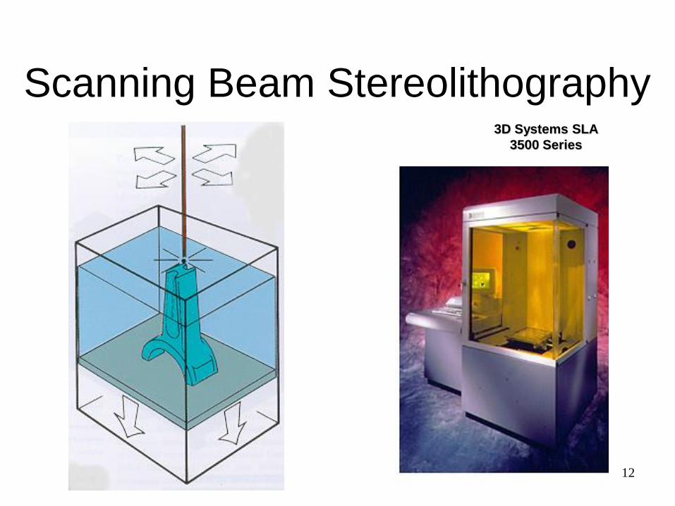
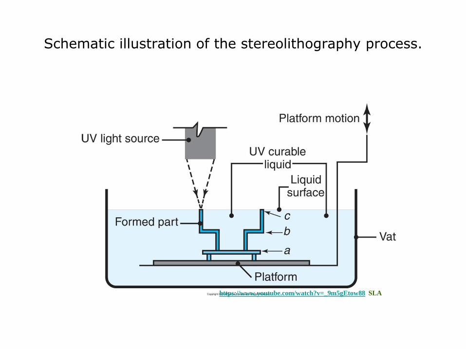
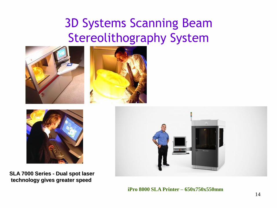
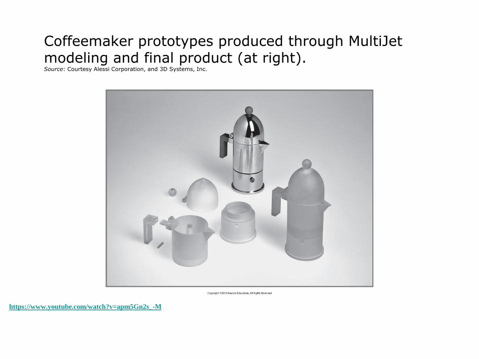
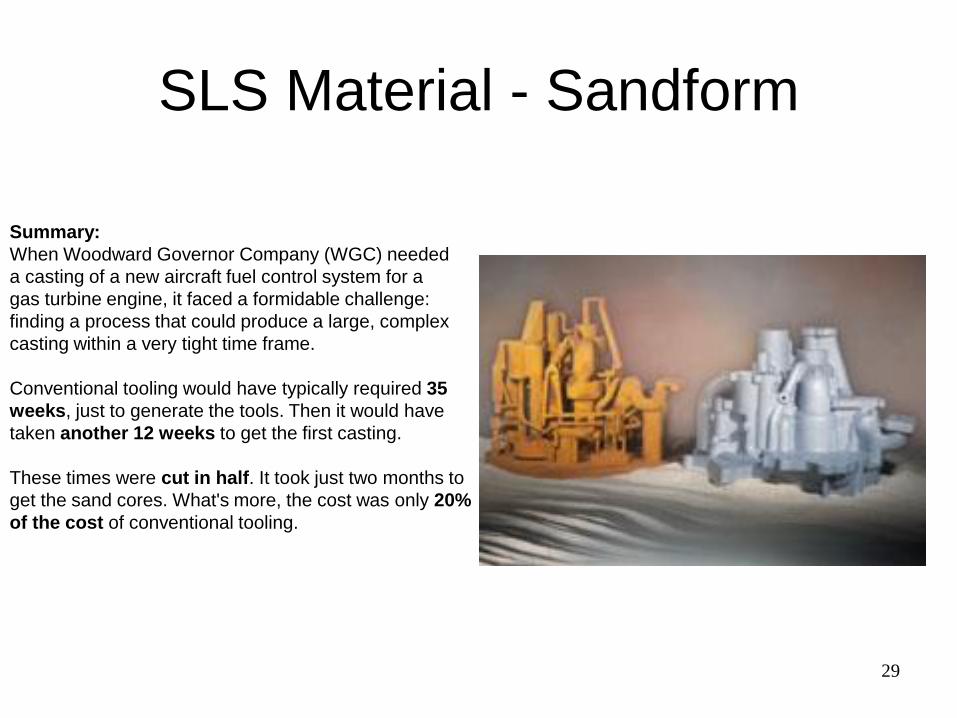
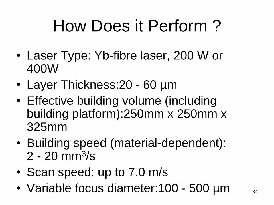
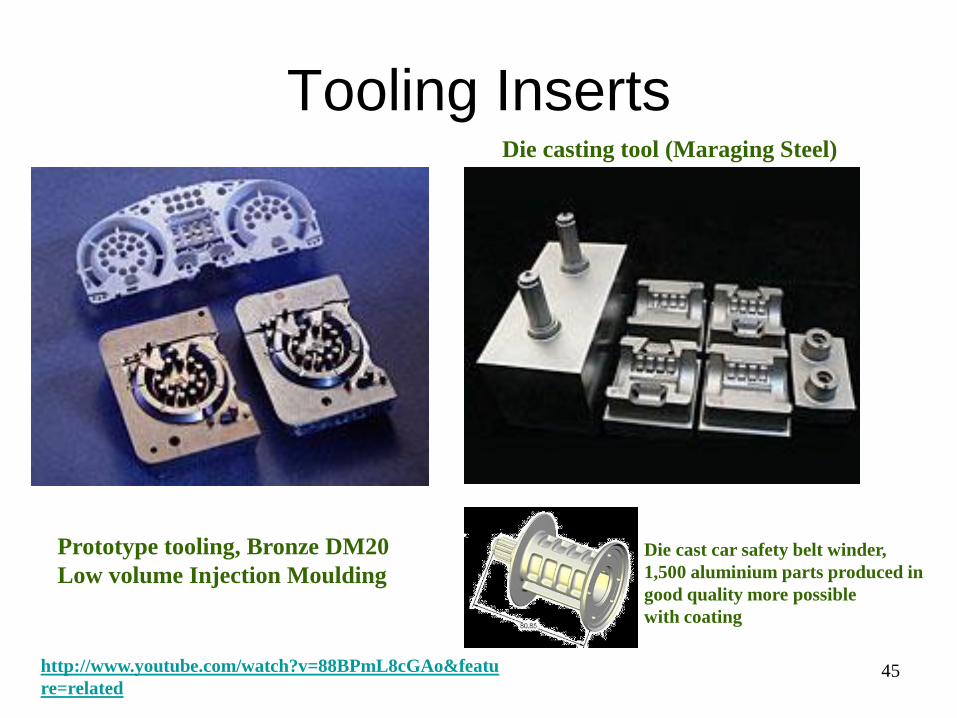
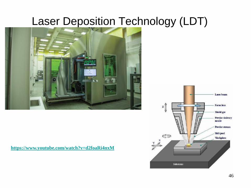
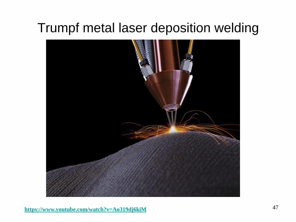
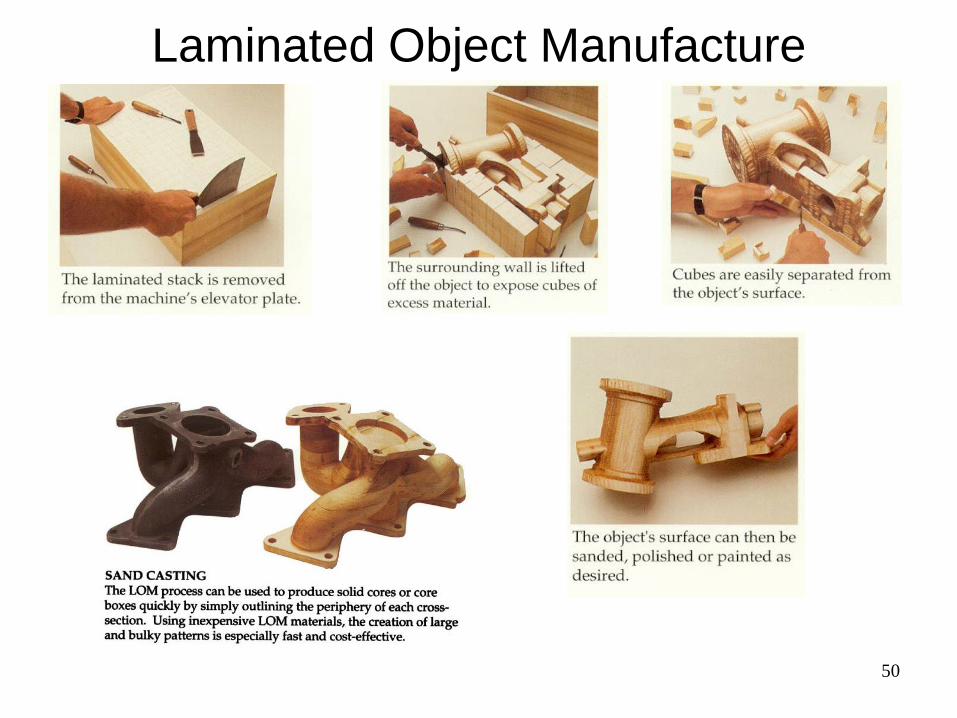
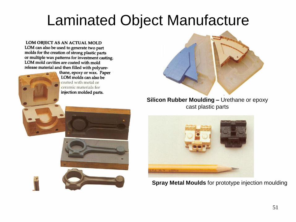
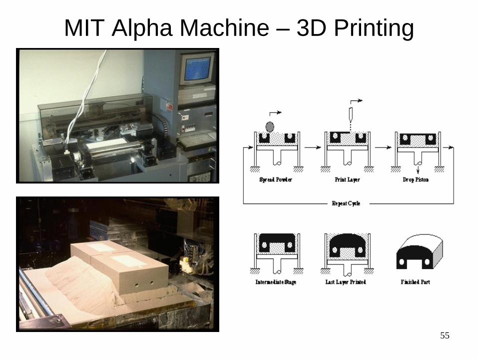
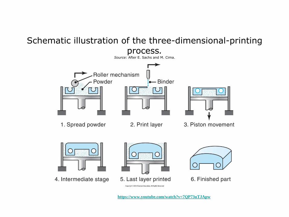
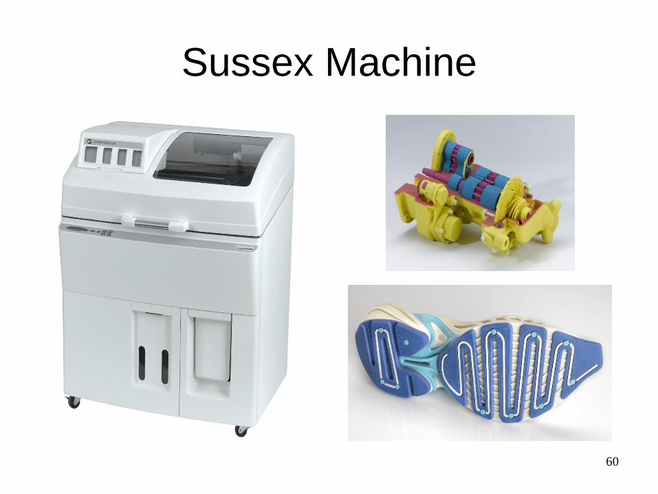
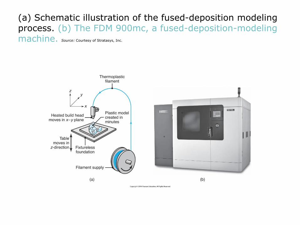
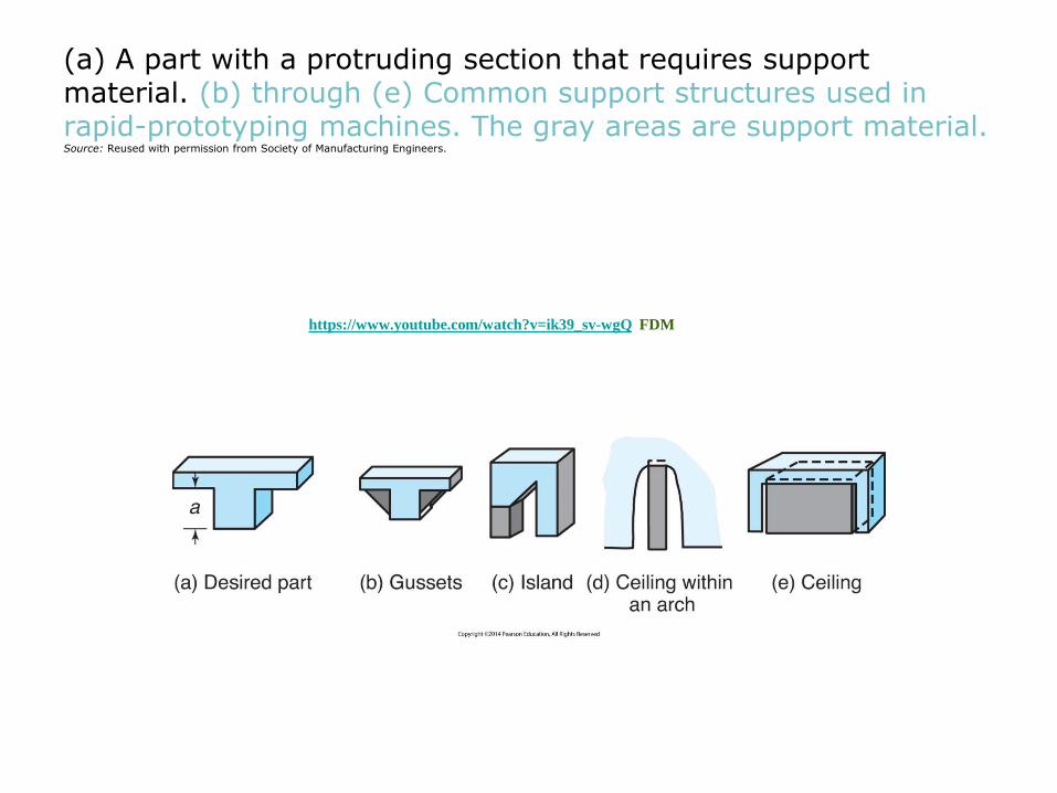
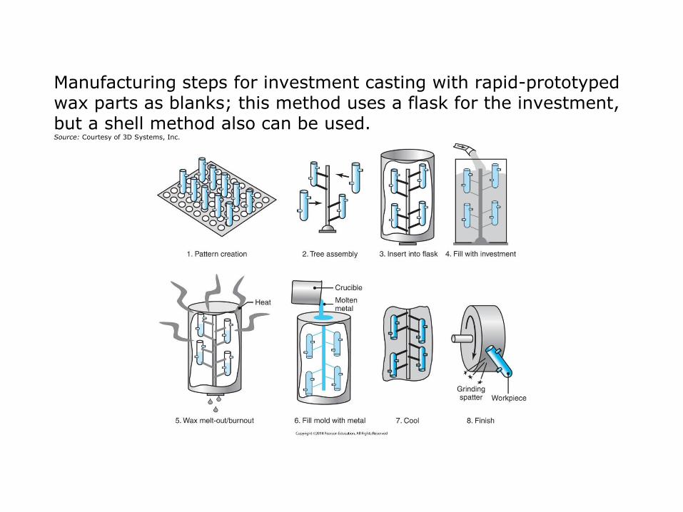

76
httpwwwyoutubecomwatchv=MrQr_gdI-ssampfeature=endscreenampNR=1
REP RAP
httpwwwyoutubecomwatchv=FUB1WgiAFHg
Hp Polymer jet
httpswwwyoutubecomwatchv=rjYA1w1uuAw
httpswwwyoutubecomwatchv=s9IdZ2pI5dA additive subtractive manufacture
Hair Dryer

Hair Dryer


