Page 1
RRA Report of
Ethylene & Styrene recovery unit, M/s
IOCL, Panipat
Doc No: A822-17-43-RA-0001
Rev. No.: 0
Page 1 of 79
Template No. 5-0000-0001-T2 Rev. 2 28.11.14 Copyrights EIL All rights reserved
RAPID RISK ANALYSIS REPORT
OF
ETHYLENE & STYRENE RECOVERY UNIT
Job. No. A822
Indian Oil Corporation Limited, Panipat
0 15.02.16 Issued as Final PS DK PJK
A 07.01.16 Issued for Comments PS DK PJK
Rev No Date Purpose Prepared By Reviewed By Approved By
Page 2
RRA Report of
Ethylene & Styrene recovery unit, M/s
IOCL, Panipat
Doc No: A822-17-43-RA-0001
Rev. No.: 0
Page 2 of 79
Template No. 5-0000-0001-T2 Rev. 2 28.11.14 Copyrights EIL All rights reserved
PREFACE
Engineers India Limited (EIL), New Delhi, has been entrusted by M/s Indian Oil Corporation
Limited (IOCL), Panipat to carry out the Rapid Risk Analysis of the facilities i.e Ethylene recovery
Unit (ERU) including Styrene Recovery Unit (STRU) and other facilities like Horton Sphere /
Mounded Bullet at Panipat Naphtha Cracker.
M/s Indian Oil Corporation Ltd. (IOCL) is India's largest public corporation in terms of revenue and
is one of the five Maharatna status companies of India. M/s IOCL Panipat Refinery was set up in
1998 at Baholi village, Panipat, Haryana. It is the seventh refinery belonging to IOCL and is one of
South East Asia’s largest integrated petrochemicals plants.
Rapid Risk Analysis identifies the Hazards associated with the Facility, analyses the
Consequences, draws suitable Conclusions and provides necessary Recommendations to
mitigate the Hazard/ Risk.
This Rapid Risk Analysis is based on the information made available at the time of this study. EIL
has exercised all reasonable skill, care and diligence in carrying out the study. However, this
report is not deemed to be any undertaking, warrantee or certificate.
Page 3
RRA Report of
Ethylene & Styrene recovery unit, M/s
IOCL, Panipat
Doc No: A822-17-43-RA-0001
Rev. No.: 0
Page 3 of 79
Template No. 5-0000-0001-T2 Rev. 2 28.11.14 Copyrights EIL All rights reserved
TABLE OF CONTENTS
1 EXECUTIVE SUMMARY .............................................................................................................................................. 5
1.1 INTRODUCTION ............................................................................................................ 5
1.2 APPROACH METHODOLOGY ....................................................................................... 5
1.3 MAJOR FINDINGS AND RECOMMENDATIONS ........................................................... 6
2 INTRODUCTION ............................................................................................................................................................ 10
2.1 STUDY AIMS AND OBJECTIVE ................................................................................... 10
2.2 SCOPE OF WORK ....................................................................................................... 10
3 SITE CONDITION .......................................................................................................................................................... 11
3.1 GENERAL .................................................................................................................... 11
3.2 SITE, LOCATION AND VICINITY ................................................................................. 11
3.3 METEOROLOGICAL CONDITIONS ............................................................................. 11
4 HAZARDS ASSOCIATED WITH THE FACILITIES ...................................................................................... 15
4.1 GENERAL .................................................................................................................... 15
4.2 HAZARDS ASSOCIATED WITH FLAMMABLE MATERIALS........................................ 15
5 HAZARD IDENTIFICATION ...................................................................................................................................... 17
5.1 GENERAL .................................................................................................................... 17
5.2 MODES OF FAILURE ................................................................................................... 17
5.3 SELECTED FAILURE CASES ...................................................................................... 18
6 CONSEQUENCE ANALYSIS ................................................................................................................................... 20
6.1 GENERAL .................................................................................................................... 20
6.2 CONSEQUENCE ANALYSIS MODELLING .................................................................. 20
6.2.1 DISCHARGE RATE ............................................................................................... 20
6.2.2 DISPERSION ......................................................................................................... 20
6.2.3 FLASH FIRE .......................................................................................................... 20
6.2.4 JET FIRE ............................................................................................................... 21
6.2.5 POOL FIRE ........................................................................................................... 21
6.2.6 VAPOR CLOUD EXPLOSION ............................................................................... 21
6.2.7 FIREBALL .............................................................................................................. 21
6.3 SIZE AND DURATION OF RELEASE ........................................................................... 22
6.4 DAMAGE CRITERIA ..................................................................................................... 22
6.4.1 LFL OR FLASH FIRE ............................................................................................. 22
6.4.2 THERMAL HAZARD DUE TO POOL FIRE, JET FIRE AND FIRE BALL ................ 22
6.4.3 VAPOR CLOUD EXPLOSION ............................................................................... 23
6.5 CONSEQUENCE ANALYSIS FOR NEW PROPOSED UNITS ..................................... 24
6.5.1 ERU ....................................................................................................................... 24
6.5.2 STRU ..................................................................................................................... 25
6.5.3 MOUNDED BULLET & SPHERE ........................................................................... 26
6.5.4 MODIFICATION IN EXISTING REFINERY ............................................................ 28
6.5.5 MODIFICATION IN NCU........................................................................................ 28
7 CONCLUSIONS & RECOMMENDATIONS ...................................................................................................... 29
8 GLOSSARY ....................................................................................................................................................................... 33
9 REFERENCES ................................................................................................................................................................ 35
ANNEXURE-I: CONSEQUENCE ANALYSIS HAZARD DISTANCES
ANNEXURE-II: FIGURES FOR CONSEQUENCE ANALYSIS
Page 4
RRA Report of
Ethylene & Styrene recovery unit, M/s
IOCL, Panipat
Doc No: A822-17-43-RA-0001
Rev. No.: 0
Page 4 of 79
Template No. 5-0000-0001-T2 Rev. 2 28.11.14 Copyrights EIL All rights reserved
LIST OF TABLES
Table 1: New Proposed Process Facilities under Modification Project......................................................... 10
Table 2: Atmospheric Parameter ..................................................................................................................................... 11
Table 3: Average Mean Wind Speed (m/s) ................................................................................................................. 12
Table 4: Pasquill Stability Classes ................................................................................................................................... 13
Table 5: Weather Conditions .............................................................................................................................................. 14
Table 6: Size of Release ...................................................................................................................................................... 22
Table 7: Damage Due to Incident Thermal Radiation Intensity ........................................................................ 23
Table 8: Damage Effects of Blast Overpressure ...................................................................................................... 23
Page 5
RRA Report of
Ethylene & Styrene recovery unit, M/s
IOCL, Panipat
Doc No: A822-17-43-RA-0001
Rev. No.: 0
Page 5 of 79
Template No. 5-0000-0001-T2 Rev. 2 28.11.14 Copyrights EIL All rights reserved
1 EXECUTIVE SUMMARY
1.1 INTRODUCTION
Panipat Naphtha Cracker Complex (PNC) of M/s Indian oil Corporation Ltd (IOCL) processes
Naphtha to produce Ethylene and Propylene streams for downstream polymer units and pyrolysis
gasoline (Pygas) stream as by- product. Presently capacity of the complex is 800 KTPA ethylene
with possibility to extend to 1000 KTPA Ethylene production. The Butadiene Extraction unit
(BDEU) is producing Butadiene. IOCL under joint venture has Styrene Butadiene Rubber (SBR)
plant at the same location. Presently, only Benzene is being recovered from the Hydrogenated
Pygas. This Pygas from PNC has good potential of Styrene which in case recovered can be used
as feed to the Unit. The recovered Styrene is planned to be supplied on a dedicated basis to the
SBR Plant.
Continuing with tradition of value addition & optimization of resources, another unit - Ethylene
recovery unit is also being planned to be set up. This unit - Ethylene Recovery Unit(ERU) will
extract Ethane & Ethylene from off gas of Panipat Refinery (from FCCU,DCU units) and send
them to Naphtha Cracker Unit (NCU) downstream units and thereby increasing profitability of
PNC as well as minimizing impact of refinery off gas to environment.
Therefore, IOCL has proposed production of Styrene (20 KTA), Ethylene (18.8 KTA), Ethane
(73.6 KTA), Propane (4.9 KTA), Propylene (12.0 KTA) inside Panipat Naphtha Cracker premises
with total plot area 14,000 m2 (9000 m2 for STRU & 5000 m2 for ERU including One Horton
sphere & One Mounded Bullet for storage of Hydrogenated C4 Mix/C4 Raffinate.
M/s IOCL entrusted the task of carrying out Risk Analysis study to M/s Engineers India Limited
(EIL) for obtaining Environmental Clearance. This Executive Summary provides Major Findings
and Recommendations arising out of the Rapid Risk Analysis for the proposed modification in
existing Facilities at M/s IOCL, Panipat.
1.2 APPROACH METHODOLOGY
RRA study evaluates the consequences of potential failure scenarios, assess extent of damages,
based on damage criteria’s and suggest suitable measures for mitigating the Hazard.
RRA involves identification of various potential hazards & credible failure scenarios for proposed
ERU & STRU including off-site storages & pumping, etc. and modifications in existing Refinery
and NCU complex, based on their frequency of Occurrence & resulting Consequence. Basically
two types of scenarios are identified spanning across various process facilities; Cases with high
chance of occurrence but having low consequence, e.g., Instrument Tapping Failure and Cases
with low chance of occurrence but having high consequence, e.g. Catastrophic Rupture of
Page 6
RRA Report of
Ethylene & Styrene recovery unit, M/s
IOCL, Panipat
Doc No: A822-17-43-RA-0001
Rev. No.: 0
Page 6 of 79
Template No. 5-0000-0001-T2 Rev. 2 28.11.14 Copyrights EIL All rights reserved
Pressure Vessels. Effect zones for various outcomes of failure scenarios (Flash Fire, Jet Fire,
Pool Fire, Blast overpressure etc.) are studied and identified in terms of distances on plot plan.
Based on affect zones, measures for mitigation of the hazard/risk are suggested.
1.3 MAJOR FINDINGS AND RECOMMENDATIONS
Based upon Consequence Analysis (section 6.5), the major Observations arising out of the
Consequence Analysis for Proposed Modifications are summarized below:
Ethylene Recovery Unit
1. “Instrument Tapping Failure at De-ethaniser Bottom Pump in ERU” (Case no. 6.5.1.1),
and “Instrument Tapping Failure at EBR Compressor in ERU” (Case no. 6.5.1.3), has
been modeled as a failure scenario for the Risk Analysis. The affect zone of these failure
scenario will remain mostly within unit B/L & does not pose any significant Risk on other
existing unit, however local impact may damage nearby equipment. (Refer Figure 6.5.1.1.1,
6.5.1.1.2, 6.5.1.1.3, 6.5.1.3.1, 6.5.1.3.2, 6.5.1.3.3)
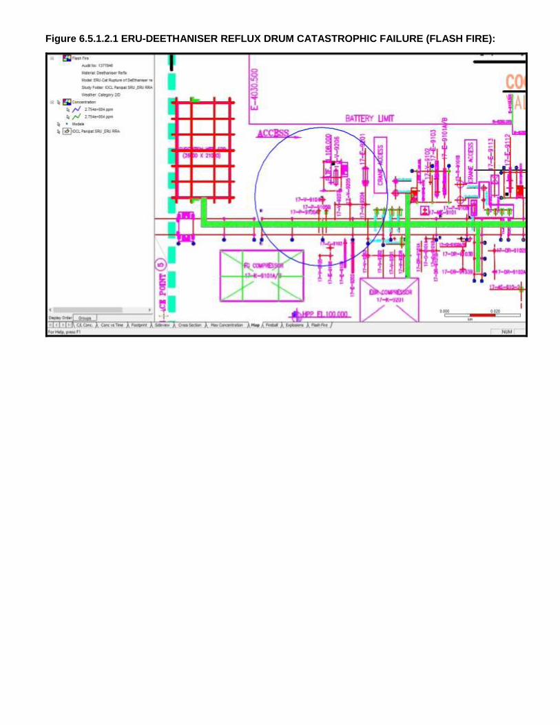
2. The affect zone of “Catastrophic Rupture of De-ethaniser Reflux Drum in ERU” (Case no.
6.5.1.2) failure scenario in case of thermal radiation intensity of 37.5 kW/m2 will remain limited
within unit B/L. In case of Late Ignition Explosion, the Overpressure of 5 psi level will extend
up to Substation and reaching beyond North, South side B/L. The results of this scenario may
be utilized while formulating/updating of Disaster Management Plan. (Refer Figure 6.5.1.2.1,
6.5.1.2.2, 6.5.1.2.3)
Styrene Recovery Unit
3. “Catastrophic Rupture of DWC Feed Surge Drum for STRU” (Case No. 6.5.2.3) may result
in late ignition explosion due to which 3 psi Overpressure waves will extend up to substation-
1, SRR-1, Benzene/C7-C8 tanks in TF-9, Master Control room, Parking area and some parts
of units like NCU & AU. (Refer Figure 6.5.2.3.2). The affect Zone of flash fire may reach up to
substation-1, SRR-1, Master Control room & Parking area.
It is suggested to locate DWC Feed Surge Drum during detail engineering in such a way that
flash fire zone shall not reach up to Master Control Room parking.
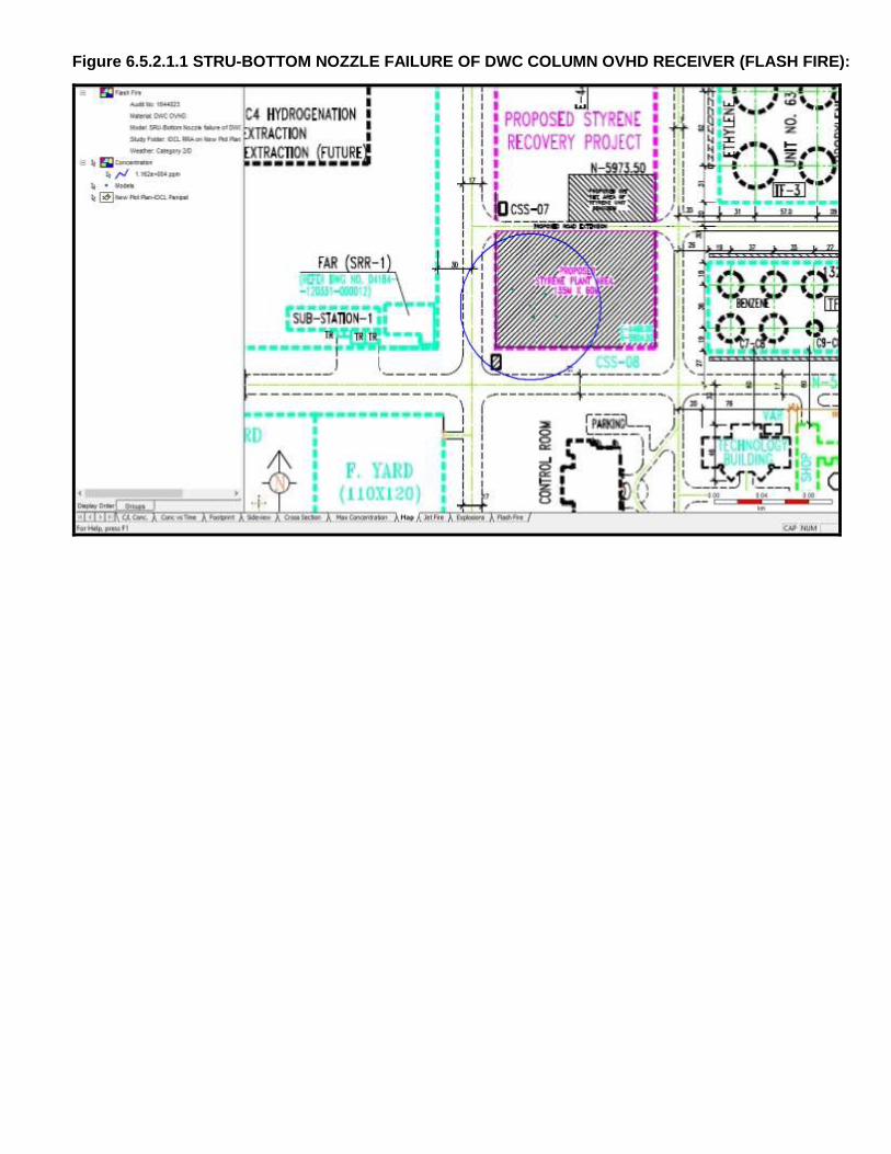
4. The affect zone of “Bottom Nozzle Failure of DWC Column Overhead Receiver for STRU”
(Case No. 6.5.2.1) failure scenario in case of thermal radiation intensity of 8.0 kW/m2 due to
Jet Fire may reach upto proposed offsite area of Styrene unit. (Refer Figure 6.5.2.1.2).
Page 7
RRA Report of
Ethylene & Styrene recovery unit, M/s
IOCL, Panipat
Doc No: A822-17-43-RA-0001
Rev. No.: 0
Page 7 of 79
Template No. 5-0000-0001-T2 Rev. 2 28.11.14 Copyrights EIL All rights reserved
It is recommended to locate Styrene and Solvent tanks in proposed offsite area of Styrene unit
during detail engineering in such a way that effects from thermal radiation of intensity 8.0
kW/m2 due to above failure scenario shall not reach up to these tanks.
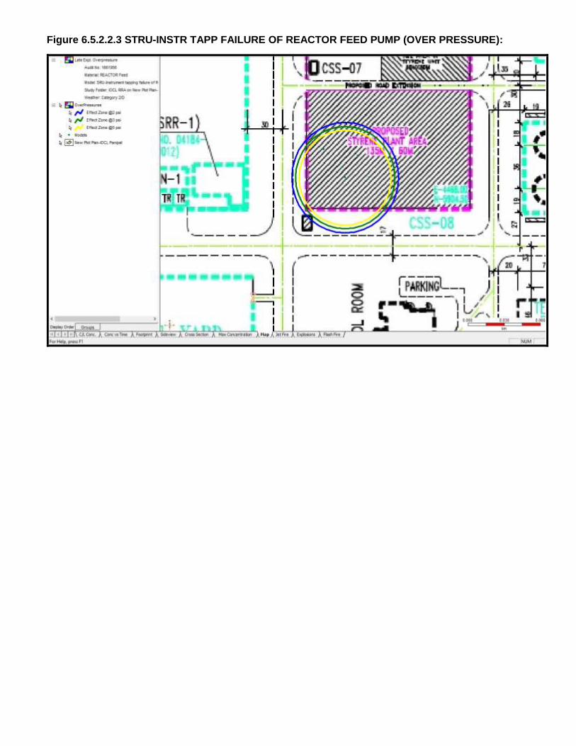
5. For failure cases like “Instrument Tapping Failure of Reactor Feed Pump for STRU”
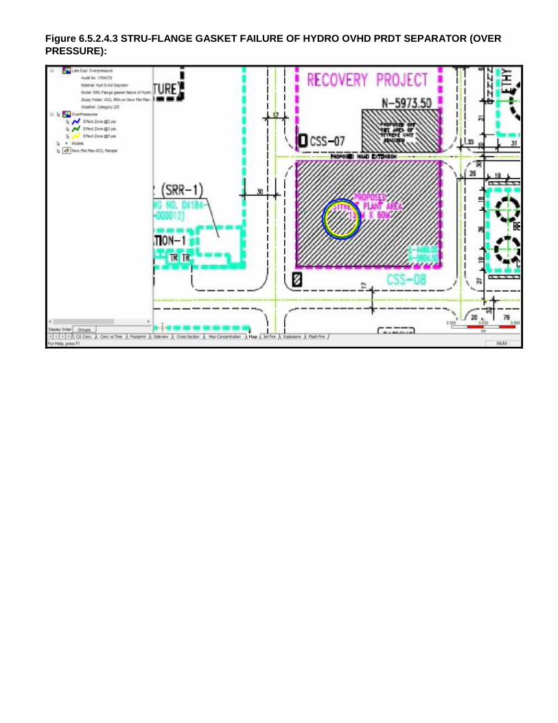
(Case No. 6.5.2.2), “Flange Gasket Failure of Hydro OVHD Product Separator for STRU”
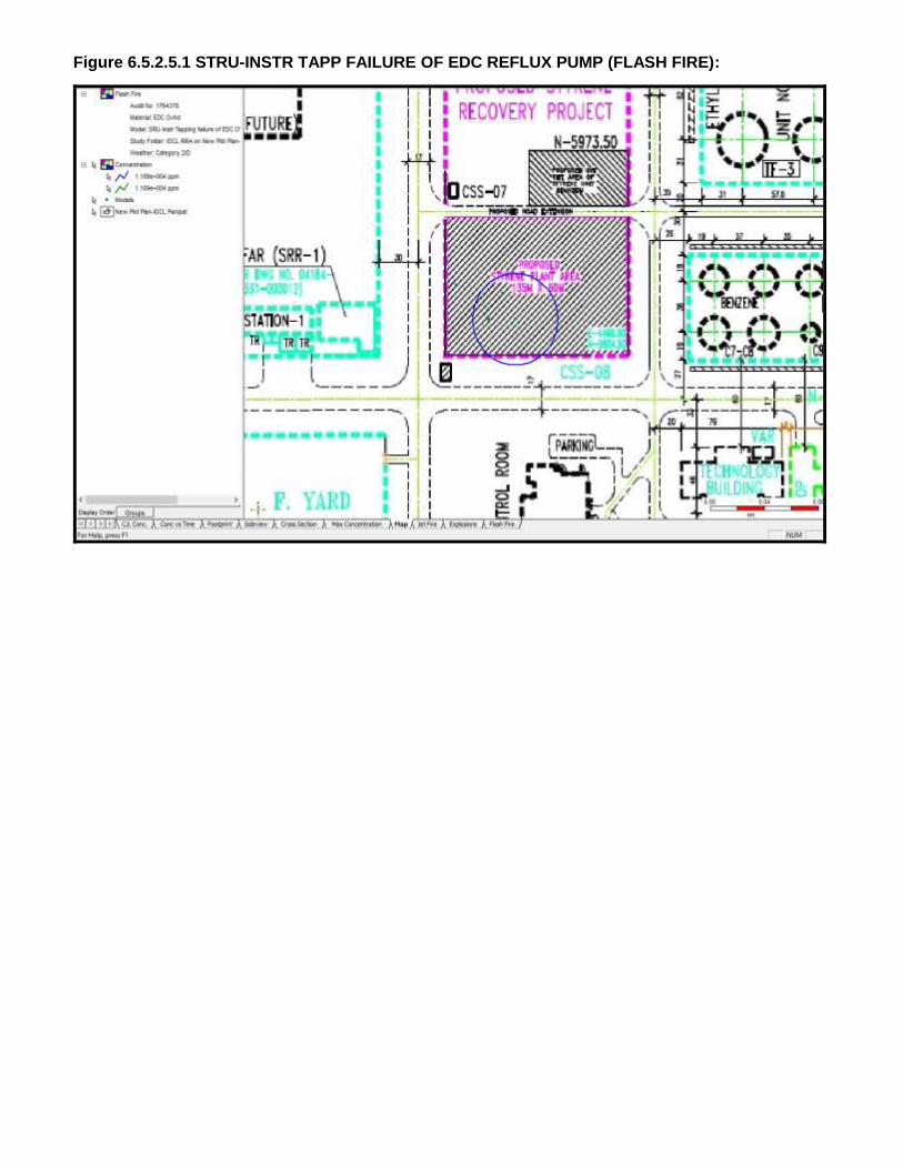
(Case No. 6.5.2.4) & “Instrument Tapping Failure of EDC Reflux Pump for STRU” (Case
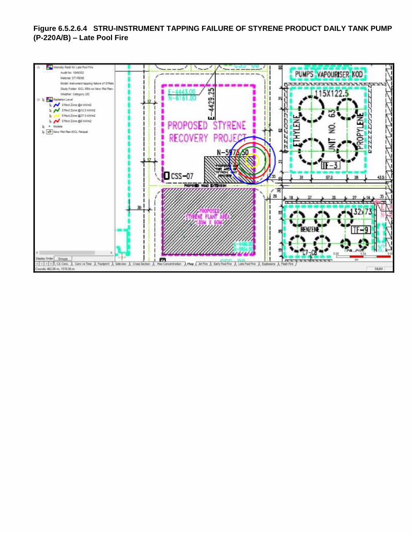
No. 6.5.2.5), “instrument tapping failure of Styrene Product daily tank pump” (Case No.
6.5.2.6) consequence analysis has been carried out. The 5 psi Overpressure waves due to
Late Ignition Explosion may remain within STRU. (Refer Graph 6.5.2.2.3, 6.5.2.4.3, 6.5.2.5.3,
6.5.2.6.3). The affect zone due to flammable impacts like Jet fire and Pool fire, will remain
mostly within STRU B/L and may affect nearby equipment. (Refer Graph 6.5.2.2.2, 6.5.2.4.2,
6.5.2.5.2, 6.5.2.6.2 & 6.5.2.6.4).
Mounded Bullets and Sphere
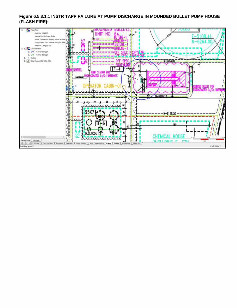
6. The 5 psi Overpressure waves due to Late Ignition Explosion in case of “Instrument Tapping
Failure at pump discharge in Mounded bullet pump house” (Case no. 6.5.3.1) affect OC-
01 in TF-4. (Refer Graph 6.5.3.1.3). The affect zone due to flammable impacts (Thermal
Radiation of 12.5 kW/m2) like Jet fire in this case extend up to OC-01 in TF-4. (Refer Graph
No. 6.5.3.1.2).
It is recommended either to relocate OC-01 present in TF-4 in safe location or make blast
resistant construction with positive pressurization as per applicable standard.
7. The 5 psi Overpressure waves due to Late Ignition Explosion & thermal radiation of intensity
12.5 kW/m2 due to Jet Fire in case of “Flange Gasket Failure at pump discharge in C4 Mix
Sphere pump house” (Case no. 6.5.3.3) will be realized in TF-7 & pipe rack in this area
which can turn into major hazard if left unchecked. (Refer Graph No. 6.5.3.3.2 & 6.5.3.3.3).
It is recommended to ensure fire proofing of Sphere & pipe rack supports falling in Thermal
Radiation of Intensity 12.5 kW/m2 affect zone.
8. It is observed that LFL zone will remain within the boundary of IOCL Panipat complex for
“Catastrophic Rupture of C4 mix off spec Sphere” (Case No. 6.5.3.2).However,
overpressure of 3 psi is reaching 220 Meter outside of east side boundary wall of IOCL,
Panipat complex. ( Refer graph no. 6.5.3.2.1, 6.5.3.2.2 & 6.5.3.2.3)
It is recommended no permanent habitation up to 220 meter from east side boundary wall of
IOCL, Panipat complex.
Page 8
RRA Report of
Ethylene & Styrene recovery unit, M/s
IOCL, Panipat
Doc No: A822-17-43-RA-0001
Rev. No.: 0
Page 8 of 79
Template No. 5-0000-0001-T2 Rev. 2 28.11.14 Copyrights EIL All rights reserved
Panipat Refinery & NCU
9. Flammable and Explosive Scenarios like “Top Nozzle Failure of Refinery Off Gas KOD”,
(Case No. 6.5.4.1) and “Flange Gasket Failure of Heat Exchanger”, (Case No. 6.5.5.1)
were modeled for Modified section in Refinery area near DCU and NCU respectively, it is
observed that the Consequence Outcomes like Late Ignition Explosion (5 psi) as well as
Thermal Radiation (12.5 kW/m2) will remain within B/L of specific unit. No significant
consequence has been observed in Modified section in Refinery area near DCU and NCU.
a) Recommendations for Construction Safety during execution of Modification Project
Proper Barricading of the proposed unit to be done from live running process units during
construction phase. Hydrocarbon detectors to be provided along the barricading to detect
any hydrocarbon in vicinity of construction area.
Proper material movement path within the IOCL Panipat Refinery and NCU Complex to be
identified during the construction phase of the project.
b) General Recommendations
Cases like catastrophic Rupture are highly unlikely events and pose significant
consequence hence their Results should be utilized while formulating/updating of Disaster
Management Plan (DMP).
Proper checking of personnel at entry gates for Inflammable materials to be ensured to
avoid presence of any unidentified source of ignition.
Safe Escape Route and Access route during high severity situation like catastrophic
Rupture and high frequency cases like instrument tapping failure should be identified
Emergency Mock drills & Fire Drill to be carried out at organization level to ensure
preparation of the personnel working in IOCL Panipat Refinery and NCU Complex for
handling any emergency situation.
c) General Mitigating Measures
General Mitigating measures are those measures in place to minimize the loss of containment
Event and, hazards arising out of Loss of containment. These include:
Rapid detection of an uncommon event (HC leak, Flame etc.) and alarm arrangement and
development of subsequent quick isolation mechanism for major inventory.
Measures for controlling / minimization of Ignition sources inside the IOCL Panipat
Refinery and NCU Complex. Active and Passive Fire Protection for critical equipment and
major structures.
Content under para C is for guidance.
Page 9
RRA Report of
Ethylene & Styrene recovery unit, M/s
IOCL, Panipat
Doc No: A822-17-43-RA-0001
Rev. No.: 0
Page 9 of 79
Template No. 5-0000-0001-T2 Rev. 2 28.11.14 Copyrights EIL All rights reserved
d) Ignition Control
Ignition control will reduce the likelihood of fire events. This is the key for reducing the risk
within facilities processing flammable materials. As part of mitigation measure it is strongly
recommended to consider minimization of the traffic movement within the IOCL Panipat
Refinery and NCU Complex (Classification of Roads).
e) Preventive Maintenance for Critical Equipments
In order to reduce the failure frequency of critical Equipments, the following are
recommended:
Instrument tapping, small bore tapping and process vessels should be inspected
regularly for integrity check. Periodic health check of equipment, instruments and
maintenance of all equipment & piping are required to be ensured. Periodic calibration
of instruments and testing of alarms, trips, interlocks should be given due attention
High head pumps, which are handling Hydrocarbon, are needed to be identified.
i. Their seals, instruments and accessories are to be monitored closely
ii. A detailed preventive maintenance plan to be prepared and followed.
Surge Drums , Reflux drums and high inventory vessels whose rupture may lead to
massive consequences , to be identified and following to be ensured:
i. Monitoring of vessel internals during shut down.
ii. A detailed preventive maintenance plan to be prepared and followed.
Page 10
RRA Report of
Ethylene & Styrene recovery unit, M/s
IOCL, Panipat
Doc No: A822-17-43-RA-0001
Rev. No.: 0
Page 10 of 79
Template No. 5-0000-0001-T2 Rev. 2 28.11.14 Copyrights EIL All rights reserved
2 INTRODUCTION
2.1 STUDY AIMS AND OBJECTIVE
The objectives of the Rapid Risk Analysis are to identify and quantify all potential failure modes
that may lead to hazardous consequences and extent. Typical hazardous consequences include
fire, explosion and toxic releases.
The Rapid Risk analysis will also identify potential hazardous consequences having impacts on
population and property in the vicinity of the facilities, and provides information necessary in
developing strategies to prevent accidents and formulate the Disaster Management Plan.
The Rapid Risk Analysis includes the following steps:
a) Identification of Failure Cases within the Process and Off-Site Facilities
b) Evaluate Process Hazards emanating from the identified potential Accidental Scenarios.
c) Analyze the Damage Effects to surroundings due to such Incidents.
d) Suggest Mitigating Measures to reduce the Hazard / Risk.
The Risk analysis study has been carried out using the Risk Assessment Software Program
‘PHAST ver. 6.7 developed by DNV Technica.
2.2 SCOPE OF WORK
The study addresses the hazards that can be realized due to operations associated with the
proposed facilities under Modification Project. It covers the following proposed facilities of M/s
IOCL, Panipat Complex:
Table 1: New Proposed Process Facilities under Modification Project
S. No. Description
1. Ethylene Recovery Unit(ERU)
2. Styrene Recovery Unit(STRU)
3. Mounded Bullets/Sphere
Page 11
RRA Report of
Ethylene & Styrene recovery unit, M/s
IOCL, Panipat
Doc No: A822-17-43-RA-0001
Rev. No.: 0
Page 11 of 79
Template No. 5-0000-0001-T2 Rev. 2 28.11.14 Copyrights EIL All rights reserved
3 SITE CONDITION
3.1 GENERAL
This chapter describes the location of M/s IOCL Panipat Refinery and NCU Complex and
Meteorological Data, which have been used for the Rapid Risk Analysis.
3.2 SITE, LOCATION AND VICINITY
The proposed project site for setting up of Styrene Recovery unit (STRU) and Ethylene Recovery
unit (ERU) for of M/s IOCL is located at village Baljatan, Tehsil Matlauda, district Panipat in the
state of Haryana.
3.3 METEOROLOGICAL CONDITIONS
The consequences of released toxic or flammable material are largely dependent on the
prevailing weather conditions. For the assessment of major scenarios involving release of toxic or
flammable materials, the most important meteorological parameters are those that affect the
atmospheric dispersion of the escaping material. The crucial variables are wind direction, wind
speed, atmospheric stability and temperature. Rainfall does not have any direct bearing on the
results of the risk analysis; however, it can have beneficial effects by absorption / washout of
released materials. Actual behavior of any release would largely depend on prevailing weather
condition at the time of release.
For the Risk Analysis study, Meteorological data of nearest station have been taken from the
Climatological Tables of Observatories in India (1961-1990) published by Indian Meteorological
Department, Pune.
Atmospheric Parameters
The Climatological data which have been used for the Risk Analysis study is summarized below:
Table 2: Atmospheric Parameter
Sl. No. Parameter Average Value Considered For Study
1. Ambient Temperature (OC) 28
2. Atmospheric Pressure (mm Hg) 760
3. Relative Humidity (%) 56
4. Solar Radiation flux (kW/m2) 0.70
Page 12
RRA Report of
Ethylene & Styrene recovery unit, M/s
IOCL, Panipat
Doc No: A822-17-43-RA-0001
Rev. No.: 0
Page 12 of 79
Template No. 5-0000-0001-T2 Rev. 2 28.11.14 Copyrights EIL All rights reserved
Wind Speed and Wind Direction
Based on the Meteorological data provided by IOCL, it is observed that calm weather conditions
can be experienced for 22% of the time in a year.
Average wind speed of magnitude less than 1 m/s blows for around 34% of the time in a year and
wind speed more than 1 m/s blows for 44% of the time. Predominant wind speed for IOCL-
Panipat is 2 m/s. The predominant wind direction is from NW and SE directions
Table 3: Average Mean Wind Speed (m/s)
Jan Feb Mar April May June July Aug Sep Oct Nov Dec
N 1.39 1.39 1.54 1.88 2.15 1.97 1.80 1.34 1.26 0.90 0.97 1.09
D 0.66 0.68 0.71 0.84 1.17 1.44 1.10 0.71 0.66 0.39 0.35 0.48
Weather Category
One of the most important characteristics of atmosphere is its stability. Stability of atmosphere is
its tendency to resist vertical motion or to suppress existing turbulence. This tendency directly
influences the ability of atmosphere to disperse pollutants emitted into it from the facilities. In most
dispersion scenarios, the relevant atmospheric layer is that nearest to the ground, varying in
thickness from a few meters to a few thousand meters. Turbulence induced by buoyancy forces in
the atmosphere is closely related to the vertical temperature gradient.
Temperature normally decreases with increasing height in the atmosphere. The rate at which the
temperature of air decreases with height is called Environmental Lapse Rate (ELR). It will vary
from time to time and from place to place. The atmosphere is said to be stable, neutral or unstable
according to ELR is less than, equal to or greater than Dry Adiabatic Lapse Rate (DALR), which is
a constant value of 0.98°C/100 meters.
Pasquill stability parameter, based on Pasquill – Gifford categorization, is such a meteorological
parameter, which decreases the stability of atmosphere, i.e., the degree of convective turbulence.
Pasquill has defined six stability classes ranging from `A' (extremely unstable) to `F' (stable). Wind
speeds, intensity of solar radiation (daytime insulation) and nighttime sky cover have been
identified as prime factors defining these stability categories. Below Table indicates the various
Pasquill stability classes.
Page 13
RRA Report of
Ethylene & Styrene recovery unit, M/s
IOCL, Panipat
Doc No: A822-17-43-RA-0001
Rev. No.: 0
Page 13 of 79
Template No. 5-0000-0001-T2 Rev. 2 28.11.14 Copyrights EIL All rights reserved
Table 4: Pasquill Stability Classes
Surface Wind Speed
(meter/s)
Day time solar radiation Night time cloud cover
Strong Medium Slight Thin < 3/8 Medium 3/8 Overcast >4/5
< 2 A A – B B - - D
2 – 3 A – B B C E F D
3 – 5 B B – C C D E D
5 – 6 C C – D D D D D
> 6 C D D D D D
Legend: A = Very unstable, B = Unstable, C = Moderately unstable, D = Neutral, E = Moderately
stable, F = stable
When the atmosphere is unstable and wind speeds are moderate or high or gusty, rapid
dispersion of pollutants will occur. Under these conditions, pollutant concentrations in air will be
moderate or low and the material will be dispersed rapidly. When the atmosphere is stable and
wind speed is low, dispersion of material will be limited and pollutant concentration in air will be
high. In general worst dispersion conditions (i.e. contributing to greater hazard distances) occur
during low wind speed and very stable weather conditions, such as that at 2F weather condition
(i.e. 2 m/s wind speed and Pasquill Stability F).
Stability category for the present study is identified based on the cloud amount and wind speed.
For risk analysis the representative average annual weather conditions are assessed based on
the following:
Wind speed less than 1 m/s would be experienced for 34% of time in a year. In order to realize
the hazardous distances, weather stability of “F” was selected with wind speed 1 m/s & average
wind speed of 2 m/s with stability class of “D” was selected. In the present study, the entire range
of representative wind speeds and associated wind directions, both during the day and night, and
cloud amount have been considered.
The consequence results are reported in tabular form for all the weather conditions and are
represented graphically for prevalent weather condition.
Page 14
RRA Report of
Ethylene & Styrene recovery unit, M/s
IOCL, Panipat
Doc No: A822-17-43-RA-0001
Rev. No.: 0
Page 14 of 79
Template No. 5-0000-0001-T2 Rev. 2 28.11.14 Copyrights EIL All rights reserved
Table 5: Weather Conditions
Wind Speed Pasquill Stability
1 F
2 D
Note: For RRA following plot plan has been used.
1. Overall Plot Plan of Naphtha Cracker Complex (Doc. No.: 6556-00-16-47-0001 Rev H)
2. Overall Plot Plan of Panipat Refinery (Doc. No.:6673-LAY-000-LD-0001 Rev 00)
3. Overall Plot Plan of NCU+AU (Doc. No.:6673-LAY-910-LD-0001 Rev 00)
Page 15
RRA Report of
Ethylene & Styrene recovery unit, M/s
IOCL, Panipat
Doc No: A822-17-43-RA-0001
Rev. No.: 0
Page 15 of 79
Template No. 5-0000-0001-T2 Rev. 2 28.11.14 Copyrights EIL All rights reserved
4 HAZARDS ASSOCIATED WITH THE FACILITIES
4.1 GENERAL
Ethylene, Styrene Recovery & offsite Mounded Bullets/Sphere handles a number of hazardous
materials like Styrene, C4 Mix, Ethylene which have a potential to cause fire and explosion
hazards. This chapter describes in brief the hazards associated with these materials.
4.2 HAZARDS ASSOCIATED WITH FLAMMABLE MATERIALS
STYRENE, ETHYLENE & C4 Mix
The major hazards from these types of hydrocarbons are fire and radiation. Any spillage or loss of
containment of heavier hydrocarbons may create a highly flammable pool of liquid around the
source of release.
If it is released at temperatures higher than the normal boiling point it can flash significantly and
would lead to high entrainment of gas phase in the liquid phase. High entrainment of gas phase in
the liquid phase can lead to jet fires. On the other hand negligible flashing i.e. release at
temperatures near boiling points would lead to formation of pools and then pool fire.
Vapors may be ignited rapidly when exposed to heat, spark, open flame or other source of
ignition. When mixed with air and exposed to an ignition source, flammable vapors can burn in the
open or explode in confined spaces. Being heavier than air, vapors may travel long distances to
an ignition source and flash back. Runoff to sewer may cause fire or explosion hazard. Refer to
below table for properties of these Hydrocarbons.
Styrene
S. No. Properties Values
1. LFL (%v/v) 1.1
2. UFL (%v/v) 6.1
3. Auto ignition temperature (°C) 490
4. Normal Boiling point (°C) 145.2
5. Heat of combustion (Kj/mol) 4219000
Page 16
RRA Report of
Ethylene & Styrene recovery unit, M/s
IOCL, Panipat
Doc No: A822-17-43-RA-0001
Rev. No.: 0
Page 16 of 79
Template No. 5-0000-0001-T2 Rev. 2 28.11.14 Copyrights EIL All rights reserved
Ethylene
Sl. No. Properties Values
1. LFL (%v/v) 2.3
2 UFL (%v/v) 3.2
3. Auto ignition temperature (°C) 450
4. Normal Boiling point (°C) -104
5. Heat of combustion (Kj/mol) 1323000
C4 Mix
Sl. No. Properties Values
1. LFL (%v/v) 1.7
2. UFL (%v/v) 10
3. Normal Boiling point (°C) -4.5
4. Heat of combustion (Kj/mol) 2521000
Page 17
RRA Report of
Ethylene & Styrene recovery unit, M/s
IOCL, Panipat
Doc No: A822-17-43-RA-0001
Rev. No.: 0
Page 17 of 79
Template No. 5-0000-0001-T2 Rev. 2 28.11.14 Copyrights EIL All rights reserved
5 HAZARD IDENTIFICATION
5.1 GENERAL
A classical definition of hazard states that hazard is in fact the characteristic of
system/plant/process that presents potential for an accident. Hence all the components of a
system/plant/process need to be thoroughly examined in order to assess their potential for
initiating or propagating an unplanned event/sequence of events, which can be termed as an
accident.
In Risk Analysis terminology a hazard is something with the potential to cause harm. Hence the
Hazard Identification step is an exercise that seeks to identify what can go wrong at the major
hazard installation or process in such a way that people may be harmed. The output of this step is
a list of events that need to be passed on to later steps for further analysis.
The potential hazards posed by the facility were identified based on the past accidents, lessons
learnt and a checklist. This list includes the following elements.
Large hole on outlet of process vessel.
“Guillotine-Breakage” of pipe-work
Small hole, cracks or small bore failure (i.e. instrument tapping failure, drains/vents failure
etc.) in piping and vessels.
Flange leaks.
Storage Tank on fire
Leaks from pump glands and similar seals.
5.2 MODES OF FAILURE
There are various potential sources of large leakage, which may release hazardous chemicals
and hydrocarbon materials into the atmosphere. These could be in form of gasket failure in
flanged joints, bleeder valve left open inadvertently, an instrument tubing giving way, pump seal
failure, guillotine failure of equipment/ pipeline or any other source of leakage. Operating
experience can identify lots of these sources and their modes of failure. A list of general
equipment and pipeline failure mechanisms is as follows:
Material/Construction Defects
Incorrect selection or supply of materials of construction
Incorrect use of design codes
Weld failures
Failure of inadequate pipeline supports
Page 18
RRA Report of
Ethylene & Styrene recovery unit, M/s
IOCL, Panipat
Doc No: A822-17-43-RA-0001
Rev. No.: 0
Page 18 of 79
Template No. 5-0000-0001-T2 Rev. 2 28.11.14 Copyrights EIL All rights reserved
Pre-Operational Failures
Failure induced during delivery at site
Failure induced during installation
Pressure and temperature effects
Overpressure
Temperature expansion/contraction (improper stress analysis and support design)
Low temperature brittle fracture (if metallurgy is incorrect)
Fatigue loading (cycling and mechanical vibration)
Corrosion Failures
Internal corrosion (e.g. ingress of moisture)
External corrosion
Cladding/insulation failure (e.g. ingress of moisture)
Cathodic protection failure, if provided
Failures due to Operational Errors
Human error
Failure to inspect regularly and identify any defects
External Impact Induced Failures
Dropped objects
Impact from transport such as construction traffic
Vandalism
Subsidence
Strong winds
Failure due to Fire
External fire impinging on pipeline or equipment
Rapid vaporization of cold liquid in contact with hot surfaces
5.3 SELECTED FAILURE CASES
A list of selected failure cases was prepared based on process knowledge, engineering judgment,
experience, past incidents associated with such facilities and considering the general
mechanisms for loss of containment. A list of cases has been identified for the consequence
analysis study based on the following:
Cases with high chance of occurrence but having low consequence: Example of such
failure cases includes two-bolt gasket leak for flanges, seal failure for pumps, instrument
tapping failure, etc. The consequence results will provide enough data for planning routine
safety exercises. This will emphasize the area where operator's vigilance is essential.
Cases with low chance of occurrence but having high consequence (The example includes
Large hole on the outlet of Pressure vessels, Catastrophic Rupture etc.)
Page 19
RRA Report of
Ethylene & Styrene recovery unit, M/s
IOCL, Panipat
Doc No: A822-17-43-RA-0001
Rev. No.: 0
Page 19 of 79
Template No. 5-0000-0001-T2 Rev. 2 28.11.14 Copyrights EIL All rights reserved
This approach ensures at least one representative case of all possible types of accidental
failure events, is considered for the consequence analysis. Moreover, the list below
includes at least one accidental case comprising of release of different sorts of highly
hazardous materials handled in the ERU, STRU & Mounded Bullets/Sphere. Although the
list does not give complete failure incidents considering all equipment’s, units, but the
consequence of a similar incident considered in the list below could be used to foresee the
consequence of that particular accident.
For selected credible failure scenarios and likely consequences (Hazard Distances due to
Flammable and Explosive Accidents) for proposed Facilities of M/s IOCL, Panipat, refer Section-
6.
S. No. Details of Failure Case Selected
Unit: ERU
1. Instrument Tapping Failure De-ethaniser Bottom Pump discharge line
2. Catastrophic Rupture of De-ethaniser Reflux Drum
3. Instrument Tapping Failure at EBR Compressor
Unit: STRU
4. Bottom Nozzle Failure of DW Column Overhead Receiver
5. Instrument Tapping Failure at Reactor Feed Pump Discharge line
6. Catastrophic Rupture DWC Feed Surge Drum
7. Flange Gasket Failure of Hydro overhead product Separator
8. Instrument Tapping Failure at EDC Reflux Pump
9. Instrument tapping failure of Styrene product daily tank pump (P-220A/B)
Unit: Mounded Bullet and Sphere
10. Instrument Tapping Failure at Mounded Bullet Pump discharge line at pump house
11. Catastrophic Rupture of C4 mix off spec Sphere
12. Flange Gasket Failure at Pump discharge line at Sphere Pump house
Unit: ERU at PR
13. Top Nozzle Failure at Refinery off gas KOD(17-V-9001)
Unit: NCU
14. Flange Gasket Failure at Heat exchanger(11-E-1303) Tube side
Page 20
RRA Report of
Ethylene & Styrene recovery unit, M/s
IOCL, Panipat
Doc No: A822-17-43-RA-0001
Rev. No.: 0
Page 20 of 79
Template No. 5-0000-0001-T2 Rev. 2 28.11.14 Copyrights EIL All rights reserved
6 CONSEQUENCE ANALYSIS
6.1 GENERAL
Consequence analysis involves the application of the mathematical, analytical and computer
models for calculation of the effects and damages subsequent to a hydrocarbon / toxic release
accident.
Computer models are used to predict the physical behavior of hazardous incidents. The model
uses below mentioned techniques to assess the consequences of identified scenarios:
Modeling of discharge rates when holes develop in process equipment/pipe work
Modeling of the size & shape of the flammable/toxic gas clouds from releases in the
atmosphere
Modeling of the flame and radiation field of the releases that are ignited and burn as jet fire,
pool fire and flash fire
Modeling of the explosion fields of releases which are ignited away from the point of release
The different consequences (Flash fire, pool fire, jet fire and Explosion effects) of loss of
containment accidents depend on the sequence of events & properties of material released
leading to the either toxic vapor dispersion, fire or explosion or both.
6.2 CONSEQUENCE ANALYSIS MODELLING
6.2.1 DISCHARGE RATE
The initial rate of release through a leak depends mainly on the pressure inside the equipment,
size of the hole and phase of the release (liquid, gas or two-phase). The release rate decreases
with time as the equipment depressurizes. This reduction depends mainly on the inventory and
the action taken to isolate the leak and blow-down the equipment.
6.2.2 DISPERSION
Releases of gas into the open air form clouds whose dispersion is governed by the wind, by
turbulence around the site, the density of the gas and initial momentum of the release. In case of
flammable materials the sizes of these gas clouds above their Lower Flammable Limit (LFL) are
important in determining whether the release will ignite. In this study, the results of dispersion
modeling for flammable materials are presented LFL quantity.
6.2.3 FLASH FIRE
A flash fire occurs when a cloud of vapors/gas burns without generating any significant
overpressure. The cloud is typically ignited on its edge, remote from- the leak source. The
combustion zone moves through the cloud away from the ignition point.
Page 21
RRA Report of
Ethylene & Styrene recovery unit, M/s
IOCL, Panipat
Doc No: A822-17-43-RA-0001
Rev. No.: 0
Page 21 of 79
Template No. 5-0000-0001-T2 Rev. 2 28.11.14 Copyrights EIL All rights reserved
The duration of the flash fire is relatively short but it may stabilize as a continuous jet fire from the
leak source. For flash fires, an approximate estimate for the extent of the total effect zone is the
area over which the cloud is above the LFL.
6.2.4 JET FIRE
Jet fires are burning jets of gas or atomized liquid whose shape is dominated by the momentum of
the release. The jet flame stabilizes on or close to the point of release and continues until the
release is stopped. Jet fire can be realized, if the leakage is immediately ignited. The effect of jet
flame impingement is severe as it may cut through equipment, pipeline or structure. The damage
effect of thermal radiation is depended on both the level of thermal radiation and duration of
exposure.
6.2.5 POOL FIRE
A cylindrical shape of the pool fire is presumed. Pool-fire calculations are then carried out as part
of an accidental scenario, e.g. in case a hydrocarbon liquid leak from a vessel leads to the
formation of an ignitable liquid pool. First no ignition is assumed, and pool evaporation and
dispersion calculations are being carried out. Subsequently late pool fires (ignition following
spreading of liquid pool) are considered. If the release is bunded, the diameter is given by the size
of the bund. If there is no bund, then the diameter is that which corresponds with a minimum pool
thickness, set by the type of surface on which the pool is spreading.
6.2.6 VAPOR CLOUD EXPLOSION
A vapor cloud explosion (VCE) occurs if a cloud of flammable gas burns sufficiently quickly to
generate high overpressures (i.e. pressures in excess of ambient). The overpressure resulting
from an explosion of hydrocarbon gases is estimated considering the explosive mass available to
be the mass of hydrocarbon vapor between its lower and upper explosive limits.
6.2.7 FIREBALL
A fire, burning sufficiently rapidly for the burning mass to rise into air as cloud or ball. The Thermal
radiation output from a fireball is characterized in terms of the fraction of combustion energy
released through radiation, emissive power, view factor and its dependence on the release
pressure.
Page 22
RRA Report of
Ethylene & Styrene recovery unit, M/s
IOCL, Panipat
Doc No: A822-17-43-RA-0001
Rev. No.: 0
Page 22 of 79
Template No. 5-0000-0001-T2 Rev. 2 28.11.14 Copyrights EIL All rights reserved
6.3 SIZE AND DURATION OF RELEASE
Leak size considered for selected failure cases are listed below.
Table 6: Size of Release
Failure Description Leak Size
Pump seal failure 6 mm hole size
Flange gasket failure 10 mm hole size
Instrument tapping failure 20 mm hole size
Large Hole in the Piping 50 mm, complete rupture of 2” drain line at the
pressure vessel outlet
The discharge duration is taken as 10 minutes for continuous release scenarios as it is
considered that it would take plant personnel about 10 minutes to detect and isolate the leak and
initiate control actions1. However credit for adequate safeguards is also considered wherever
required like any interlock, automatic tripping of pump/compressor, gas detector, any other
detection devices if provided.
6.4 DAMAGE CRITERIA
In order to appreciate the damage effect produced by various scenarios, physiological/physical
effects of the blast wave, thermal radiation or toxic vapor exposition are discussed.
6.4.1 LFL OR FLASH FIRE
Hydrocarbon vapor released accidentally will spread out in the direction of wind. If a source of
ignition finds an ignition source before being dispersed below lower flammability limit (LFL), a
flash fire is likely to occur and the flame will travel back to the source of leak. Any person caught
in the flash fire is likely to suffer fatal burn injury. Therefore, in consequence analysis, the distance
of LFL value is usually taken to indicate the area, which may be affected by the flash fire.
Flash fire (LFL) events are considered to cause direct harm to the population present within the
flammability range of the cloud. Fire escalation from flash fire such that process or storage
equipment or building may be affected is considered unlikely.
6.4.2 THERMAL HAZARD DUE TO POOL FIRE, JET FIRE AND FIRE BALL
Thermal radiation due to pool fire, jet fire or fire ball may cause various degrees of burn on human
body and damage process equipment. The damage effect due to thermal radiation intensity is
tabulated below.
1 Release duration is based on Chemical Process Quantitative Risk Analysis, CCPS.
Page 23
RRA Report of
Ethylene & Styrene recovery unit, M/s
IOCL, Panipat
Doc No: A822-17-43-RA-0001
Rev. No.: 0
Page 23 of 79
Template No. 5-0000-0001-T2 Rev. 2 28.11.14 Copyrights EIL All rights reserved
Table 7: Damage Due to Incident Thermal Radiation Intensity
Incident Radiation Intensity
(Kw/M²) Type of Damage
37.5 Sufficient to cause damage to process equipment
32.0 Maximum flux level for thermally protected tanks containing flammable
liquid
12.5 Minimum energy required for piloted ignition of wood, melting of plastic
tubing etc.
8.0 Maximum heat flux for un-insulated tanks
4.0 Sufficient to cause pain to personnel if unable to reach cover within 20
seconds. However blistering of skin (1st degree burns) is likely.
The hazard distances to the 37.5 kW/m2, 12.5 kW/m2, and 4 kW/m2 radiation levels, selected
based on their effect on population, buildings and equipment were modeled using PHAST 6.7.
6.4.3 VAPOR CLOUD EXPLOSION
In the event of explosion taking place within the plant, the resultant blast wave will have damaging
effects on equipment, structures, building and piping falling within the overpressure distances of
the blast. Tanks, buildings, structures etc. can only tolerate low level of overpressure. Human
body, by comparison, can withstand higher overpressure. But injury or fatality can be inflicted by
collapse of building of structures. The damage effect of blast overpressure is tabulated below.
Table 8: Damage Effects of Blast Overpressure
Blast Overpressure (PSI) Damage Level
5.0 Major structure damage
3.0 Oil storage tank failure
2.0 Repairable damage, pressure vessels remain intact, light
structures collapse
1.0 Window pane breakage possible, causing some injuries
The hazard distances to the 5 psi, 3 psi and 2 psi overpressure levels, selected based on their
effects on population, buildings and equipment were modeled using PHAST 6.7.
Page 24
RRA Report of
Ethylene & Styrene recovery unit, M/s
IOCL, Panipat
Doc No: A822-17-43-RA-0001
Rev. No.: 0
Page 24 of 79
Template No. 5-0000-0001-T2 Rev. 2 28.11.14 Copyrights EIL All rights reserved
6.5 CONSEQUENCE ANALYSIS FOR NEW PROPOSED UNITS
This section discusses the consequences of selected failure scenarios for modifications under
ERU & STRU Project whose affect zones pose significant consequence and subsequent Risk on
Facility. The consequence distances are reported in tabular form for all weather conditions in
Annexure-I. The consequences has been analyzed and represented graphically in Annexure-II
for the prevalent weather condition.
6.5.1 ERU
NOTE: Refer Figures 6.5.1.1.1 to 6.5.1.3.3 in Annexure-II
6.5.1.1 Instrument Tapping Failure of De-ethaniser Bottom Pump: From the Consequence
Analysis, it can be observed that LFL shall be travelling up to a distance of 41 m. The Jet Fire
radiation intensity of 4, 12.5 & 37.5 kW/m2 would extend up to a distance of 60 m, 48 & 41 m
respectively. The 2, 3 & 5 psi blast overpressures distance shall extend up to a distance of 57 m,
53 m & 49 m respectively.
Based upon the hazard distances it may be observed that hazardous affect zones for the selected
failure scenario shall not be extending beyond the B/L’s of the unit and may cause damage to the
nearby equipment & Substation. (Refer graph no. 6.5.1.1.1, 6.5.1.1.2 & 6.5.1.1.3)
6.5.1.2 Catastrophic Rupture of De-ethaniser Reflux Drum: From the Consequence
Analysis, it can be concluded that LFL may be extended up to a distance of 26 m. The Fireball
radiation intensity of 4, 12.5 & 37.5 kW/m2 would extend up to a distance of 240 m, 127 & 41 m
respectively. The 2, 3 & 5 psi blast overpressures wave will travel up to a distance of 122 m, 99
m & 77 m respectively.
By analyzing the above results, it can be observed that thermal radiation distances of 37.5 kW/m2
will remain with B/L of this unit. The 5 psi blast overpressure is extending beyond the North, South
side B/L’s & may cause damage to the nearby equipment & Substation. (Refer graph no.
6.5.1.2.1, 6.5.1.2.2 & 6.5.1.2.3)
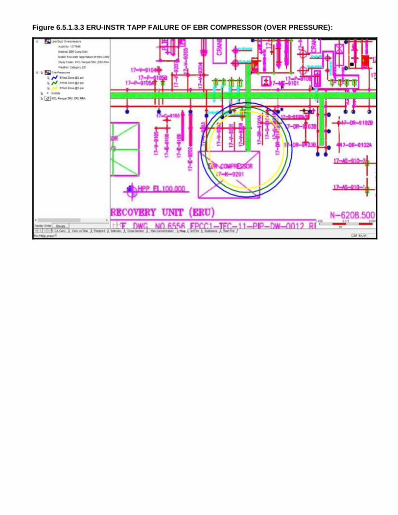
6.5.1.3 Instrument Tapping Failure at EBR Compressor: From the Consequence Analysis, it
can be concluded that LFL may be extended up to a distance of 17 m. The Jet Fire radiation
intensity of 4, 12.5 k & 37.5 W/m2 would extend up to a distance of 37 m, 30 m & 25 m
respectively. The 2, 3 & 5 psi blast overpressures wave would travel up to a distance of 17 m, 15
m & 14 m respectively.
Page 25
RRA Report of
Ethylene & Styrene recovery unit, M/s
IOCL, Panipat
Doc No: A822-17-43-RA-0001
Rev. No.: 0
Page 25 of 79
Template No. 5-0000-0001-T2 Rev. 2 28.11.14 Copyrights EIL All rights reserved
Based upon the hazard distances it may be observed that hazardous affect zones for the selected
failure scenario shall not be extending beyond the B/L’s of the unit and may cause damage to the
nearby equipment. (Refer graph no. 6.5.1.3.1, 6.5.1.3.2 & 6.5.1.3.3)
6.5.2 STRU
NOTE: Refer Figures 6.5.2.1.1 to 6.5.2.6.4 in Annexure-II
6.5.2.1 Bottom Nozzle Failure of DWC Column Overhead Receiver: From the consequence
analysis of the selected failure scenario it is observed that LFL hazard distance is extended up to
60 m. The Jet Fire Radiation Intensity of 4, 12.5 & 37.5 kW/m2 would extend up to a distance of
111 m, 86 m & 71 m respectively. The 2, 3 & 5 psi blast overpressure waves travel up to a
distance of 90 m, 83 m & 77 m respectively.
Based upon the hazard distances it may be observed that LFL & overpressure of magnitude of 5
psi affect zones for the selected failure scenario is extending beyond the West side B/L’s of the
unit and South side access to STRU. The thermal radiation of intensity 8.0 kW/m2 is reaching up
to proposed Styrene offsite area. (Refer graph no. 6.5.2.1.1, 6.5.2.1.2 & 6.5.2.1.3)
6.5.2.2 Instrument Tapping Failure of Reactor Feed Pump: From the consequence analysis of
the selected failure scenario it is observed that LFL hazard distance is extended up to 30 m. The
Jet Fire Radiation Intensity of 4, 12.5 & 37.5 kW/m2 would extend up to a distance of 53 m, 41 m
& 35 m respectively. The 2, 3 & 5 psi blast overpressure waves travel up to a distance of 43 m, 40
m & 38 m respectively.
Based upon the hazard distances it may be observed that hazardous affect zones for the selected
failure scenario shall not be extending beyond the B/L’s of the unit and may cause damage to the
nearby equipment. (Refer graph no. 6.5.2.2.1, 6.5.2.2.2 & 6.5.2.2.3)
6.5.2.3 Catastrophic Rupture of DWC Feed Surge Drum : From the consequence analysis of
the selected failure scenario it is observed that LFL hazard distance is extended up to 142 m. The
2, 3 & 5 psi blast overpressure waves travel up to a distance of 229 m, 198 m & 180 m
respectively.
Based upon the hazard distances it may be observed that hazardous affect zones (LFL) for the
selected failure scenario shall be extending beyond the West and South side of B/L’s of the unit
and may reach up to Substation-1,SRR-1 & parking of Master control room. The hazard distance
due to overpressure of magnitude of 3 psi is reaching upto Benzene/C7-C8 tanks in TF-9,SRR-
1,S/S-1,Master control room & some parts of units like NCU,AU . (Refer graph no. 6.5.2.3.1 &
6.5.2.3.2).
Page 26
RRA Report of
Ethylene & Styrene recovery unit, M/s
IOCL, Panipat
Doc No: A822-17-43-RA-0001
Rev. No.: 0
Page 26 of 79
Template No. 5-0000-0001-T2 Rev. 2 28.11.14 Copyrights EIL All rights reserved
6.5.2.4 Flange Gasket Failure of Hydro OVHD Product Separator: From the consequence
analysis of the selected failure scenario it is observed that LFL hazard distance is extended up to
14 m. The Jet Fire Radiation Intensity of 4, 8 & 12.5 would extend up to a distance of 29 m, 24 m
& 21 m respectively. The 2, 3 & 5 psi blast overpressure waves travel up to a distance of 18 m,
16 m & 15 m respectively.
Based upon the hazard distances it may be observed that hazardous affect zones for the selected
failure scenario shall not be extending beyond the B/L’s of the unit and may cause damage to the
nearby equipment. (Refer graph no. 6.5.2.4.1, 6.5.2.4.2 & 6.5.2.4.3).
6.5.2.5 Instrument Tapping Failure of EDC Reflux Pump: From the consequence analysis of
the selected failure scenario it is observed that LFL hazard distance is extended up to 31 m. The
Jet Fire Radiation Intensity of 4, 8, 12.5 & 37.5 kW/m2 would extend up to a distance of 53 m, 46
m, 42 m & 35 m respectively. The 2, 3 & 5 psi blast overpressure waves travel up to a distance of
44 m, 41 m & 38 m respectively.
Based upon the hazard distances it may be observed that hazardous affect zones for the selected
failure scenario shall be extending beyond the South side of B/L’s of the unit and may cause
damage to the nearby equipment. (Refer graph no. 6.5.2.5.1, 6.5.2.5.2 & 6.5.2.5.3).
6.5.2.6 Instrument Tapping Failure of Styrene Product daily tank Pump: it is observed from
the consequence analysis of the selected failure scenario that LFL hazard distance is extended
up to 17 m. The Jet Fire Radiation Intensity of 4, 8, 12.5 & 37.5 kW/m2 would extend up to a
distance of 30 m, 26 m, 24 m & 19 m respectively. The Late Pool Fire Radiation Intensity of 4, 8,
12.5 & 37.5 kW/m2 would extend up to a distance of 33 m, 25 m, 20 m & 9 m respectively. The 2,
3 & 5 psi blast overpressure waves travel up to a distance of 16 m, 15 m & 14 m respectively.
Based upon the hazard distances it may be observed that hazardous affect zones for the selected
failure scenario shall be reaching up to East side access road and may cause damage to the
nearby equipment. (Refer graph no. 6.5.2.6.1, 6.5.2.6.2, 6.5.2.6.3 & 6.5.2.6.4).
6.5.3 MOUNDED BULLET & SPHERE
NOTE: Refer Figures 6.5.3.1.1 to 6.5.3.3.3 in Annexure- II
6.5.3.1 Instrument Tapping Failure at pump discharge at Mounded bullet pump house: From
the Consequence results, it can be observed that LFL may be extended up to a distance of 51 m.
The Thermal radiation distance due to jet fire of radiation Intensity of 4, 12.5 & 37.5 kW/m2 can
Page 27
RRA Report of
Ethylene & Styrene recovery unit, M/s
IOCL, Panipat
Doc No: A822-17-43-RA-0001
Rev. No.: 0
Page 27 of 79
Template No. 5-0000-0001-T2 Rev. 2 28.11.14 Copyrights EIL All rights reserved
extend up to a distance of 69 m, 55 m & 46 m respectively. The over pressure distances due to
late ignition explosion of 2,3 & 5 psi blast wave may reach up to a distance of 71 m, 66 m & 62 m.
Based on consequence analysis of failure scenario it could be realized that hazardous zone may
cross the West side B/L’s of the mounded bullet pump house, reach up to the hydrogenated C4
mounded bullet, North, South, West side access and may damage West side Operator Cabin(OC-
1) in TF4, and nearby equipment (due to flammable and explosive impacts). The mounded
bullets are quite safe and do not pose major risk as it provides intrinsically passive and safe
environment and eliminates the possibility of Boiling Liquid Expanding Vapor Explosion (BLEVE).
The cover of the mound protects the vessel from fire engulfment, radiation from a fire in close
proximity. (Refer graph no. 6.5.3.1.1, 6.5.3.1.2, 6.5.3.1.3)
6.5.3.2 Catastrophic Rupture of C4 mix Off Spec Sphere: From the Consequence results, it
can be observed that LFL may be extended up to a distance of 475 m. The Thermal radiation
distance due to Fireball of radiation Intensity of 4 & 12.5 kW/m2 can extend up to a distance of
1090 m, & 559 m respectively. The over pressure distances due to late ignition explosion of 2,3 &
5 psi blast wave may reach up to a distance of 839 m, 700 m & 627 m.
Based on Consequence Analysis, the LFL zone is not extending beyond B/L of the IOC Panipat
Complex. The overpressure 3 psi is reaching beyond the boundary wall of IOC Panipat Complex.
The probability of realization of this event is very less and hence the results so obtained may be
referred as guideline for preparing Disaster Management plan. (Refer graph no. 6.5.3.2.1,
6.5.3.2.2, 6.5.3.2.3).
6.5.3.3 Flange Gasket Failure of pump discharge at Sphere Area: From the Consequence
results of the selected failure scenario it can be observed that LFL may be extended up to a
distance of 20 m. The Thermal radiation distance due to Jet fire of radiation Intensity of 4, 12.5 &
37.5 kW/m2 can extend up to a distance of 30 m, 29 m & 24 m respectively. The over pressure
distances due to late ignition explosion of 2,3 & 5 psi blast wave may reach up to a distance of 29
m, 27 m & 25 m respectively.
Based upon the hazard distances it may be observed that hazardous affect zones for the selected
failure scenario shall be extending beyond the B/L’s of the Sphere pump-house, East side access
and may cause damage to the nearby equipment & East side pipe rack. (Refer graph no.
6.5.3.3.1, 6.5.3.3.2 & 6.5.3.3.3).
Page 28
RRA Report of
Ethylene & Styrene recovery unit, M/s
IOCL, Panipat
Doc No: A822-17-43-RA-0001
Rev. No.: 0
Page 28 of 79
Template No. 5-0000-0001-T2 Rev. 2 28.11.14 Copyrights EIL All rights reserved
6.5.4 MODIFICATION IN EXISTING REFINERY
6.5.4.1 Top Nozzle Failure of Refinery Off gas KOD: From the Consequence results of the
selected failure scenario it can be observed that LFL may be extended up to a distance of 26 m.
The Thermal radiation distance due to Jet Fire of radiation Intensity of 4 & 12.5 kW/m2 can extend
up to a distance of 30 m & 22m respectively. The over pressure distances due to late ignition
explosion of 2,3 & 5 psi blast wave may reach up to a distance of 31 m, 28 m & 26 m respectively.
Based on consequence analysis of failure scenario it could be realized that hazardous zone is
crossing the B/L’s of the new ERU-Amine Area. As per figure 6.5.4.1.3, the over pressure
distance of 5 Psi level is crossing the B/L’s of the new ERU-Amine Area & may cause damage to
the nearby equipment. As per figure 6.5.4.1.2 the Jet fire thermal distances of radiation Intensity
of 12.5 kW/m2 crossing the B/L’s of the new ERU-Amine Area. (Refer graph no. 6.5.4.1.1,
6.5.4.1.2 & 6.5.4.1.3).
6.5.5 MODIFICATION IN NCU
6.5.5.1 Flange Gasket Failure of Heat Exchanger: From the Consequence results of the
selected failure scenario it can be observed that LFL may be extended up to a distance of 4 m.
The Thermal radiation distance due to Jet fire radiation Intensity of 4 kW/m2 can extend up to a
distance of 8 m.
Based on consequence analysis of failure scenario it could be realized that hazardous zone may
not cross the B/L’s of the unit. (Refer graph no. 6.5.5.1.1 & 6.5.5.1.2).
Page 29
RRA Report of
Ethylene & Styrene recovery unit, M/s
IOCL, Panipat
Doc No: A822-17-43-RA-0001
Rev. No.: 0
Page 29 of 79
Template No. 5-0000-0001-T2 Rev. 2 28.11.14 Copyrights EIL All rights reserved
7 CONCLUSIONS & RECOMMENDATIONS
The detailed consequence analysis of release of inventory in case of failure scenarios has been
modeled in terms of Release Rate, Dispersion, Flammability and Explosive characteristics, which
have been discussed in detail in this Report. Based upon Consequence Analysis (section 6.5), the
major Observations arising out of the Consequence Analysis for Proposed Modifications are
summarized below:
Ethylene Recovery Unit
1. “Instrument Tapping Failure at De-ethaniser Bottom Pump in ERU” (Case no. 6.5.1.1),
and “Instrument Tapping Failure at EBR Compressor in ERU” (Case no. 6.5.1.3), has
been modeled as a failure scenario for the Risk Analysis. The affect zone of these failure
scenario will remain mostly within unit B/L & does not pose any significant Risk on other
existing unit, however local impact may damage nearby equipment. (Refer Figure 6.5.1.1.1,
6.5.1.1.2, 6.5.1.1.3, 6.5.1.3.1, 6.5.1.3.2, 6.5.1.3.3)
2. The affect zone of “Catastrophic Rupture of De-ethaniser Reflux Drum in ERU” (Case no.
6.5.1.2) failure scenario in case of thermal radiation intensity of 37.5 kW/m2 will remain limited
within unit B/L. In case of Late Ignition Explosion, the Overpressure of 5 psi level will extend
up to Substation and reaching beyond North, South side B/L. The results of this scenario may
be utilized while formulating/updating of Disaster Management Plan. (Refer Figure 6.5.1.2.1,
6.5.1.2.2, 6.5.1.2.3)
Styrene Recovery Unit
3. “Catastrophic Rupture of DWC Feed Surge Drum for STRU” (Case No. 6.5.2.3) may result
in late ignition explosion due to which 3 psi Overpressure waves will extend up to substation-
1, SRR-1, Benzene/C7-C8 tanks in TF-9, Master Control room, Parking area and some parts
of units like NCU & AU. (Refer Figure 6.5.2.3.2). The affect Zone of flash fire may reach up to
substation-1, SRR-1, Master Control room & Parking area.
It is suggested to locate DWC Feed Surge Drum during detail engineering in such a way that
flash fire zone shall not reach up to Master Control Room parking.
4. The affect zone of “Bottom Nozzle Failure of DWC Column Overhead Receiver for STRU”
(Case No. 6.5.2.1) failure scenario in case of thermal radiation intensity of 8.0 kW/m2 due to
Jet Fire may reach upto proposed offsite area of Styrene unit. (Refer Figure 6.5.2.1.2).
Page 30
RRA Report of
Ethylene & Styrene recovery unit, M/s
IOCL, Panipat
Doc No: A822-17-43-RA-0001
Rev. No.: 0
Page 30 of 79
Template No. 5-0000-0001-T2 Rev. 2 28.11.14 Copyrights EIL All rights reserved
It is recommended to locate Styrene and Solvent tanks in proposed offsite area of Styrene unit
during detail engineering in such a way that effects from thermal radiation of intensity 8.0
kW/m2 due to above failure scenario shall not reach up to these tanks.
5. For failure cases like “Instrument Tapping Failure of Reactor Feed Pump for STRU”
(Case No. 6.5.2.2), “Flange Gasket Failure of Hydro OVHD Product Separator for STRU”
(Case No. 6.5.2.4) & “Instrument Tapping Failure of EDC Reflux Pump for STRU” (Case
No. 6.5.2.5), “instrument tapping failure of Styrene Product daily tank pump” (Case No.
6.5.2.6) consequence analysis has been carried out. The 5 psi Overpressure waves due to
Late Ignition Explosion may remain within STRU. (Refer Graph 6.5.2.2.3, 6.5.2.4.3, 6.5.2.5.3,
6.5.2.6.3). The affect zone due to flammable impacts like Jet fire and Pool fire, will remain
mostly within STRU B/L and may affect nearby equipment. (Refer Graph 6.5.2.2.2, 6.5.2.4.2,
6.5.2.5.2, 6.5.2.6.2 & 6.5.2.6.4).
Mounded Bullets and Sphere
6. The 5 psi Overpressure waves due to Late Ignition Explosion in case of “Instrument Tapping
Failure at pump discharge in Mounded bullet pump house” (Case no. 6.5.3.1) affect OC-
01 in TF-4. (Refer Graph 6.5.3.1.3). The affect zone due to flammable impacts (Thermal
Radiation of 12.5 kW/m2) like Jet fire in this case extend up to OC-01 in TF-4. (Refer Graph
No. 6.5.3.1.2).
It is recommended either to relocate OC-01 present in TF-4 in safe location or make blast
resistant construction with positive pressurization as per applicable standard.
7. The 5 psi Overpressure waves due to Late Ignition Explosion & thermal radiation of intensity
12.5 kW/m2 due to Jet Fire in case of “Flange Gasket Failure at pump discharge in C4 Mix
Sphere pump house” (Case no. 6.5.3.3) will be realized in TF-7 & pipe rack in this area
which can turn into major hazard if left unchecked. (Refer Graph No. 6.5.3.3.2 & 6.5.3.3.3).
It is recommended to ensure fire proofing of Sphere & pipe rack supports falling in Thermal
Radiation of Intensity 12.5 kW/m2 affect zone.
8. It is observed that LFL zone will remain within the boundary of IOCL Panipat complex for
“Catastrophic Rupture of C4 mix off spec Sphere” (Case No. 6.5.3.2).However,
overpressure of 3 psi is reaching 220 Meter outside of east side boundary wall of IOCL,
Panipat complex. ( Refer graph no. 6.5.3.2.1, 6.5.3.2.2 & 6.5.3.2.3)
It is recommended no permanent habitation up to 220 meter from east side boundary wall of
IOCL, Panipat complex.
Page 31
RRA Report of
Ethylene & Styrene recovery unit, M/s
IOCL, Panipat
Doc No: A822-17-43-RA-0001
Rev. No.: 0
Page 31 of 79
Template No. 5-0000-0001-T2 Rev. 2 28.11.14 Copyrights EIL All rights reserved
Panipat Refinery & NCU
9. Flammable and Explosive Scenarios like “Top Nozzle Failure of Refinery Off Gas
KOD”, (Case No. 6.5.4.1) and “Flange Gasket Failure of Heat Exchanger”, (Case No.
6.5.5.1) were modeled for Modified section in Refinery area near DCU and NCU
respectively, it is observed that the Consequence Outcomes like Late Ignition Explosion (5
psi) as well as Thermal Radiation (12.5 kW/m2) will remain within B/L of specific unit. No
significant consequence has been observed in Modified section in Refinery area near DCU
and NCU.
a) Recommendations for Construction Safety during execution of Modification Project
Proper Barricading of the proposed unit to be done from live running process units during
construction phase. Hydrocarbon detectors to be provided along the barricading to detect
any hydrocarbon in vicinity of construction area.
Proper material movement path within the IOCL Panipat Refinery and NCU Complex to be
identified during the construction phase of the project.
b) General Recommendations
Cases like catastrophic Rupture are highly unlikely events and pose significant
consequence hence their Results should be utilized while formulating/updating of Disaster
Management plan (DMP).
Proper checking of personnel at entry gates for Inflammable materials to be ensured to
avoid presence of any unidentified source of ignition.
Safe Escape Route and Access route during high severity situation like catastrophic
Rupture and high frequency cases like instrument tapping failure should be identified
Emergency Mock drills & Fire Drill to be carried out at organization level to ensure
preparation of the personnel working in IOCL Panipat Refinery and NCU Complex for
handling any emergency situation.
c) General Mitigating Measures
General Mitigating measures are those measures in place to minimize the loss of containment
Event and, hazards arising out of Loss of containment. These include:
Rapid detection of an uncommon event (HC leak, Flame etc.) and alarm arrangement and
development of subsequent quick isolation mechanism for major inventory.
Measures for controlling / minimization of Ignition sources inside the IOCL Panipat
Refinery and NCU Complex. Active and Passive Fire Protection for critical equipment and
major structures.
Page 32
RRA Report of
Ethylene & Styrene recovery unit, M/s
IOCL, Panipat
Doc No: A822-17-43-RA-0001
Rev. No.: 0
Page 32 of 79
Template No. 5-0000-0001-T2 Rev. 2 28.11.14 Copyrights EIL All rights reserved
Content under para C is for guidance.
d) Ignition Control
Ignition control will reduce the likelihood of fire events. This is the key for reducing the risk
within facilities processing flammable materials. As part of mitigation measure it is strongly
recommended to consider minimization of the traffic movement within the IOCL Panipat
Refinery and NCU Complex (Classification of Roads).
e) Preventive Maintenance for Critical Equipments
In order to reduce the failure frequency of critical Equipments, the following are
recommended:
Instrument tapping, small bore tapping and process vessels should be inspected
regularly for integrity check. Periodic health check of equipment, instruments and
maintenance of all equipment & piping are required to be ensured. Periodic calibration
of instruments and testing of alarms, trips, interlocks should be given due attention
High head pumps, which are handling Hydrocarbon, are needed to be identified.
i. Their seals, instruments and accessories are to be monitored closely
ii. A detailed preventive maintenance plan to be prepared and followed.
Surge Drums , Reflux drums and high inventory vessels whose rupture may lead to
massive consequences , to be identified and following to be ensured:
i. Monitoring of vessel internals during shut down.
ii. A detailed preventive maintenance plan to be prepared and followed.
Page 33
RRA Report of
Ethylene & Styrene recovery unit, M/s
IOCL, Panipat
Doc No: A822-17-43-RA-0001
Rev. No.: 0
Page 33 of 79
Template No. 5-0000-0001-T2 Rev. 2 28.11.14 Copyrights EIL All rights reserved
8 GLOSSARY
CASUALTY Someone who suffers serious injury or worse i.e. including fatal
injuries. As a rough guide fatalities are likely to be half the total
casualties. But this may vary depending on the nature of the event.
HAZARD A chemical or physical condition with the potential of causing
damage.
FLAMMABILITY LIMITS In fuel-air systems, a range of compositions exists inside which a
(UFL – LFL) flame will propagate substantial distance from an
ignition source. The limiting fuel concentrations are termed as
Upper flammability or explosives limit (Fuel concentrations
exceeding this are too rich) and Lower flammability or explosives
limit (Fuel concentrations below this are too lean).
FLASH FIRE The burning of a vapor cloud at very low flame propagation speed.
Combustion products are generated at a rate low enough for
expansion to take place easily without significant overpressure
ahead or behind the flame front. The hazard is therefore only due to
thermal effects.
OVERPRESSURE Maximum pressure above atmosphere pressure experiences during
the passage of a blast wave from an explosion expressed in this
report as pounds per square inch (psi).
EXPLOSION A rapid release of energy, which causes a pressure discontinuity or
shock wave moving away from the source. An explosion can be
produced by detonation of a high explosive or by the rapid burning
of a flammable gas cloud. The resulting overpressure is sufficient to
cause damage inside and outside the cloud as the shock wave
propagation into the atmosphere beyond the cloud. Some authors
use the term deflagration for this type of explosion
DOMINO EFFECT The effect that loss of containment of one installation leads to loss
of containment of other installations
EVENT TREE A logic diagram of success and failure combinations of events used
to identify accident sequences leading to all possible consequences
of a given initiating event.
TLV “Threshold limit value” is defined as the concentration of the
substance in air that can be breathed for five consecutive 8 hours
work day (40 hours work week) by most people without side effect.
STEL “Short Term Exposure Limit” is the maximum permissible average
exposure for the time period specified (15 minutes).
Page 34
RRA Report of
Ethylene & Styrene recovery unit, M/s
IOCL, Panipat
Doc No: A822-17-43-RA-0001
Rev. No.: 0
Page 34 of 79
Template No. 5-0000-0001-T2 Rev. 2 28.11.14 Copyrights EIL All rights reserved
PASQUILL CLASS Classification to qualify the stability of the atmosphere, indicated by
a letter ranging from A, for very unstable, to F, for stable.
FREQUENCY The number of times an outcome is expected to occur in a given
period of time.
Page 35
RRA Report of
Ethylene & Styrene recovery unit, M/s
IOCL, Panipat
Doc No: A822-17-43-RA-0001
Rev. No.: 0
Page 35 of 79
Template No. 5-0000-0001-T2 Rev. 2 28.11.14 Copyrights EIL All rights reserved
9 REFERENCES
1. Loss prevention in the process industries, Hazard identification, Assessment and Control,
Frank. P. Lees (Vol. I, II & III), Published by Butterworth-Heinemann, U. K.
2. AICHE, CCPS, Chemical process Quantitative Risk Analysis
3. Guideline for Quantitative Risk assessment, ‘Purple book’.
4. IS: 15656
5. IMD Table
Page 36
RRA Report of
Ethylene & Styrene recovery unit, M/s
IOCL, Panipat
Doc No: A822-17-43-RA-0001
Rev. No.: 0
Page 36 of 79
Template No. 5-0000-0001-T2 Rev. 2 28.11.14 Copyrights EIL All rights reserved
Annexure-I
Consequence Analysis Summary Result
Page 37
Temp
( C)
P
(Kg/Cm2)4 8 12.5 37.5 4 8 12.5 37.5 4 12.5 37.5 2 3 5
1F 43 64 53 45 58 54 50
2D 41 60 48 41 57 53 49
1F 22 240 127 41 124 100 79
2D 26 240 127 41 122 99 77
1F 19 40 33 28 17 15 14
2D 17 37 30 25 17 15 14
1F 70 118 101 94 79 104 96 89
2D 60 111 94 86 71 90 83 77
1F 32 56 45 38 45 42 39
2D 30 53 41 35 43 40 38
1F 100 231 188 152
2D 142 229 198 180
1F 16 31 23 18 16 15
2D 14 29 21 18 16 15
1F 33 57 50 46 39 45 42 39
2D 31 43 46 42 35 44 41 38
1F 25 32 28 26 21 31 22 17 10 30 28 26
2D 17 30 26 24 19 33 25 20 9 16 15 14
1F 56 74 59 51 74 69 64
2D 51 69 55 46 71 66 62
1F 411 1090 559 835 685 597
2D 475 1090 559 839 700 627
1F 23 39 32 27 31 28 26
2D 20 30 29 24 29 27 25
1F 30 30 22 42 39 37
2D 26 30 22 31 28 26
1F 4 8 5
2D 4 8
Jet Fire(KW/M2) Pool Fire(KW/M2) Fire Ball(KW/M2) Over Pressure(PSI)
Styrene Product Daily
Tank Pump (P-220 A/B)
Instrument
tapping failure65 1.9
Weather
Conditio
n
23.54
18.6
30.3
Operating
Condition
Reactor Feed pump(P-
103A/B)
Instrument
tapping failure 150 6.5
3.5100
1Deethanizer bottom
Pump (17-P-9104A/B)
Instrument
tapping Failure-16
2Deethanizer reflux Drum
(17-V-9104)
Catastrophic
Rupture-12.7
3 EBR Compressor (17-
K-9201)
Instrument
tapping failure 85.4
17
4 DWC Column OVHD
Receiver (D-101)
Bottom Nozzle
failure 150 3.5
5
17
7 Hydro OVHD Product
Separator(D-201)
Flange Gasket
failure 100 3.5
6 DWC Feed Surge
Drum(D-103)
Catastrophic
Rupture
Instrument
tapping failure
9
Refinery
NCU
Mounded
Bullets/
Sphere
Styrene
Recovery
Unit
Ethylene
Recovery
Unit
14Heat exchanger (11-E-
1303)tube side
Flange Gasket
Failure60 12.34
13Refinery Offgas KOD
(17-V-9001)
Top Nozzle
Failure 40 11.5
12Pump Discharge in
Sphere Area
Flange Gasket
failure41
41
11
Consequence Analysis Summary Result for IOCL ERU & STRU Project
Unit S.No Equipment Failure Case LFL
C4 Mix Offspec SphereCatastrophic
Rupture43 4
8 EDC reflux pump (P-
202A/B)
Instrument
tapping failure 150 7.3
10
Pump Discharge in
Mounded bullet Pump
House
Page 38
Annexure-II
Figures for Consequence Analysis
Page 39
Figure 6.5.1.1.1 ERU-INSTRUMENT TAPPING FAILURE OF DEETHANISER REFLUX PUMP (FLASH
FIRE):
Page 40
Figure 6.5.1.1.2 ERU-INSTRUMENT TAPPING FAILURE OF DEETHANISER BOTT PUMP (JET FIRE):
Page 41
Figure 6.5.1.1.3 ERU-INSTRUMENT TAPPING FAILURE OF DEETHANISER BOTT PUMP (OVER
PRESSURE):
Page 42
Figure 6.5.1.2.1 ERU-DEETHANISER REFLUX DRUM CATASTROPHIC FAILURE (FLASH FIRE):
Page 43
Figure 6.5.1.2.2 ERU-DEETHANISER REFLUX DRUM CATASTROPHIC FAILURE (FIRE BALL):
Page 44
Figure 6.5.1.2.3 ERU-DEETHANISER REFLUX DRUM CATASTROPHIC FAILURE (OVER PRESSURE):
Page 45
Figure 6.5.1.3.1 ERU-INSTR TAPP FAILURE OF EBR COMPRESSOR (FLASH FIRE):
Page 46
Figure 6.5.1.3.2 ERU-INSTR TAPP FAILURE OF EBR COMPRESSOR (JET FIRE):
Page 47
Figure 6.5.1.3.3 ERU-INSTR TAPP FAILURE OF EBR COMPRESSOR (OVER PRESSURE):
Page 48
Figure 6.5.2.1.1 STRU-BOTTOM NOZZLE FAILURE OF DWC COLUMN OVHD RECEIVER (FLASH FIRE):
Page 49
Figure 6.5.2.1.2 STRU-BOTTOM NOZZLE FAILURE OF DWC COLUMN OVHD RECEIVER (JET FIRE):
Page 50
Figure 6.5.2.1.3 STRU-BOTTOM NOZZLE FAILURE OF DWC COLUMN OVHD RECEIVER (OVER
PRESSURE):
Page 51
Figure 6.5.2.2.1 STRU-INSTR TAPP FAILURE OF REACTOR FEED PUMP (FLASH FIRE):
Page 52
Figure 6.5.2.2.2 STRU-INSTR TAPP FAILURE OF REACTOR FEED PUMP (JET FIRE):
Page 53
Figure 6.5.2.2.3 STRU-INSTR TAPP FAILURE OF REACTOR FEED PUMP (OVER PRESSURE):
Page 54
Figure 6.5.2.3.1 STRU-CATASTROPHIC RUPTURE OF DWC FSD (FLASH FIRE):
Page 55
Figure 6.5.2.3.2 STRU-CATASTROPHIC RUPTURE OF DWC FSD (OVER PRESSURE):
Page 56
Figure 6.5.2.4.1 STRU-FLANGE GASKET FAILURE OF HYDRO OVHD PRDT SEPARATOR (FLASH FIRE):
Page 57
Figure 6.5.2.4.2 STRU-FLANGE GASKET FAILURE OF HYDRO OVHD PRDT SEPARATOR (JET FIRE):
Page 58
Figure 6.5.2.4.3 STRU-FLANGE GASKET FAILURE OF HYDRO OVHD PRDT SEPARATOR (OVER
PRESSURE):
Page 59
Figure 6.5.2.5.1 STRU-INSTR TAPP FAILURE OF EDC REFLUX PUMP (FLASH FIRE):
Page 60
Figure 6.5.2.5.2 STRU-INSTR TAPP FAILURE OF EDC OVHD ACCUM REFLUX PUMP (JET FIRE):
Page 61
Figure 6.5.2.5.3 STRU-INSTR TAPP FAILURE OF EDC OVHD ACCUM REFLUX PUMP (OVER
PRESSURE):
Page 62
Figure 6.5.2.6.1 STRU-INSTRUMENT TAPPING FAILURE OF STYRENE PRODUCT DAILY TANK PUMP (P-
220A/B)-FLASH FIRE:
Page 63
Figure 6.5.2.6.2 STRU-INSTRUMENT TAPPING FAILURE OF STYRENE PRODUCT DAILY TANK PUMP
(P-220A/B)- JET FIRE
Page 64
Figure 6.5.2.6.3 STRU- INSTRUMENT TAPPING FAILURE OF STYRENE PRODUCT DAILY TANK PUMP
(P-220A/B) - OVER PRESSURE
Page 65
Figure 6.5.2.6.4 STRU-INSTRUMENT TAPPING FAILURE OF STYRENE PRODUCT DAILY TANK PUMP
(P-220A/B) – Late Pool Fire
Page 66
Figure 6.5.3.1.1 INSTR TAPP FAILURE AT PUMP DISCHARGE IN MOUNDED BULLET PUMP HOUSE
(FLASH FIRE):
Page 67
Figure 6.5.3.1.2 INSTR TAPP FAILURE AT PUMP DISCHARGE IN MOUNDED BULLET PUMP HOUSE
(JET FIRE):
Page 68
Figure 6.5.3.1.3 INSTR TAPP FAILURE AT PUMP DISCHARGE IN MOUNDED BULLET PUMP HOUSE
(OVER PRESSURE):
Page 69
Figure 6.5.3.2.1 CATASTROPHIC RUPTURE OF C4 MIX OFFSPEC SPHERE (FLASH FIRE):
Page 70
Figure 6.5.3.2.2 CATASTROPHIC RUPTURE OF C4 SPHERE (FIRE BALL):
Page 71
Figure 6.5.3.2.3 CATASTROPHIC RUPTURE OF C4 SPHERE (OVER PRESSURE):
Page 72
Figure 6.5.3.3.1 FLANGE GASKET FAILURE AT PUMP DISCHARGE IN C4 MIX SPHERE PUMP HOUSE
(FLASH FIRE):
Page 73
Figure 6.5.3.3.2 FLANGE GASKET FAILURE AT PUMP DISCHARGE IN C4 MIX SPHERE PUMP HOUSE
(JET FIRE):
Page 74
Figure 6.5.3.3.3 FLANGE GASKET FAILURE AT PUMP DISCHARGE IN C4 MIX SPHERE PUMP HOUSE
(OVER PRESSURE):
Page 75
Figure 6.5.4.1.1 REFINERY- TOP NOZZLE FAILURE OF REFINERY OFFGAS KOD (17-V-9001) FLASH
FIRE:
Page 76
Figure 6.5.4.1.2 REFINERY- TOP NOZZLE FAILURE OF REFINERY OFFGAS KOD (JET FIRE):
Page 77
Figure 6.5.4.1.3 REFINERY- TOP NOZZLE FAILURE OF REFINERY OFFGAS KOD (OVER PRESSURE):
Page 78
Figure 6.5.5.1.1 NCU-FLANGE GASKET FAILURE OF HEAT EXCHANGER (FLASH FIRE):
Page 79
Figure 6.5.5.1.2 NCU-FLANGE GASKET FAILURE OF HEAT EXCHANGER (JET FIRE):