RAPPORT TECHNIQUE CEI IEC TECHNICAL REPORT TR 60909-4 Première édition First edition 2000-07 Courants de court-circuit dans les réseaux triphasés à courant alternatif – Partie 4: Exemples pour le calcul des courants de court-circuit Short-circuit currents in three-phase a.c. systems – Part 4: Examples for the calculation of short-circuit currents Commission Electrotechnique Internationale International Electrotechnical Commission Pour prix, voir catalogue en vigueur For price, see current catalogue IEC 2000 Droits de reproduction réservés Copyright - all rights reserved Aucune partie de cette publication ne peut être reproduite ni utilisée sous quelque forme que ce soit et par aucun procédé, électronique ou mécanique, y compris la photo-copie et les microfilms, sans l'accord écrit de l'éditeur. No part of this publication may be reproduced or utilized in any form or by any means, electronic or mechanical, including photocopying and microfilm, without permission in writing from the publisher. International Electrotechnical Commission 3, rue de Varembé Geneva, Switzerland Telefax: +41 22 919 0300 e-mail: [email protected]IEC web site http://www.iec.ch CODE PRIX PRICE CODE XB This is a preview of "IEC 60909-4 TR Ed. 1...". Click here to purchase the full version from the ANSI store.
Transcript
RAPPORTTECHNIQUE
CEIIEC
TECHNICALREPORT
TR 60909-4Première édition
First edition2000-07
Courants de court-circuit dans les réseauxtriphasés à courant alternatif –
Partie 4:Exemples pour le calcul des courantsde court-circuit
Short-circuit currents in three-phasea.c. systems –
Part 4:Examples for the calculation ofshort-circuit currents
Commission Electrotechnique Internationale International Electrotechnical Commission
Pour prix, voir catalogue en vigueurFor price, see current catalogue
IEC 2000 Droits de reproduction réservés Copyright - all rights reserved
Aucune partie de cette publication ne peut être reproduite niutilisée sous quelque forme que ce soit et par aucun procédé,électronique ou mécanique, y compris la photo-copie et lesmicrofilms, sans l'accord écrit de l'éditeur.
No part of this publication may be reproduced or utilized inany form or by any means, electronic or mechanical,including photocopying and microfilm, without permission inwriting from the publisher.
International Electrotechnical Commission 3, rue de Varembé Geneva, SwitzerlandTelefax: +41 22 919 0300 e-mail: [email protected] IEC web site http://www.iec.ch
CODE PRIXPRICE CODE XB
This is a preview of "IEC 60909-4 TR Ed. 1...". Click here to purchase the full version from the ANSI store.
3.3.2 Lignes (câbles et lignes aériennes).................................................................42
3.4 Calcul de "kI et ip pour les court circuits triphasés .....................................................44
3.4.1 Point de court-circuit F1 ................................................................................44
3.4.2 Point de court-circuit F2 ................................................................................46
3.4.3 Point de court-circuit F3 ................................................................................48
3.5 Calcul de "k1I et ip1 pour les courts-circuits phase terre ..............................................48
3.5.1 Point de court-circuit F1 ................................................................................48
3.5.2 Point de court-circuit F2 ................................................................................52
3.5.3 Point de court-circuit F3 ................................................................................54
3.6 Récapitulation des résultats........................................................................................54
4 Calcul des courants de court-circuit triphasés dans un réseau moyenne tension – influencedes moteurs .........................................................................................................................56
1.3 Definitions, symbols and indices, and equations ........................................................13
2 Positive-sequence, negative-sequence and zero-sequence impedances of electricalequipment............................................................................................................................13
2.1 Overhead lines, cables and short-circuit limiting reactors ..........................................13
3.6 Collection of results...................................................................................................55
4 Calculation of three-phase short-circuit currents in a medium-voltage system –influence of motors..............................................................................................................57
4.1 Problem .....................................................................................................................57
4.2 Complex calculation with absolute quantities ............................................................59
4.3 Calculation with short-circuit reactances of electrical equipment ..............................67
4.4 Calculation with per-unit quantities ...........................................................................71
4.5 Calculation with the superposition method ................................................................75
This is a preview of "IEC 60909-4 TR Ed. 1...". Click here to purchase the full version from the ANSI store.
5 Calcul des courants de court-circuit triphasés pour un groupe de production etle réseau auxiliaire ..............................................................................................................82
5.3 Calcul des courants de court-circuit ...........................................................................98
5.3.1 Point de court-circuit F1 ................................................................................98
5.3.2 Point de court-circuit F2 .............................................................................. 100
5.3.3 Point de court-circuit F3 .............................................................................. 104
5.3.4 Point de court-circuit F4 .............................................................................. 110
5.3.5 Point de court-circuit F5 .............................................................................. 114
6 Réseau d'essai pour le calcul des courants de court-circuit avec des programmesinformatiques, conformément à la CEI 60909-0................................................................. 118
5 Calculation of three-phase short-circuit currents for a power station unit andthe auxiliary network...........................................................................................................83
5.1 Problem .....................................................................................................................83
5.2 Short-circuit impedances of electrical equipment.......................................................87
6 Test network for the calculation of short-circuit currents with digital programsin accordance with IEC 60909-0........................................................................................ 119
6.1 General .................................................................................................................... 119
6.2 High-voltage test network 380 kV/ 110 kV/30 kV.................................................... 121
6.2.1 Network topology and data .......................................................................... 121
6.2.2 Short-circuit impedances of electrical equipment ........................................ 125
COURANTS DE COURT-CIRCUIT DANS LES RÉSEAUX TRIPHASÉS ÀCOURANT ALTERNATIF –
Partie 4: Exemples pour le calcul des courants de court-circuit
AVANT-PROPOS
1) La CEI (Commission Électrotechnique Internationale) est une organisation mondiale de normalisation composéede l'ensemble des comités électrotechniques nationaux (Comités nationaux de la CEI). La CEI a pour objet defavoriser la coopération internationale pour toutes les questions de normalisation dans les domaines del'électricité et de l'électronique. A cet effet, la CEI, entre autres activités, publie des Normes internationales. Leurélaboration est confiée à des comités d'études, aux travaux desquels tout Comité national intéressé par le sujettraité peut participer. Les organisations internationales, gouvernementales et non gouvernementales, en liaisonavec la CEI, participent également aux travaux. La CEI collabore étroitement avec l'Organisation Internationalede Normalisation (ISO), selon des conditions fixées par accord entre les deux organisations.
2) Les décisions ou accords officiels de la CEI concernant les questions techniques représentent, dans la mesure dupossible, un accord international sur les sujets étudiés, étant donné que les Comités nationaux intéressés sontreprésentés dans chaque comité d’études.
3) Les documents produits se présentent sous la forme de recommandations internationales. Ils sont publiés commenormes, spécifications techniques, rapports techniques ou guides et agréés comme tels par les Comités nationaux.
4) Dans le but d'encourager l'unification internationale, les Comités nationaux de la CEI s'engagent à appliquer defaçon transparente, dans toute la mesure possible, les Normes internationales de la CEI dans leurs normesnationales et régionales. Toute divergence entre la norme de la CEI et la norme nationale ou régionalecorrespondante doit être indiquée en termes clairs dans cette dernière.
5) La CEI n’a fixé aucune procédure concernant le marquage comme indication d’approbation et sa responsabilitén’est pas engagée quand un matériel est déclaré conforme à l’une de ses normes.
6) L’attention est attirée sur le fait que certains des éléments du présent rapport technique peuvent faire l’objet dedroits de propriété intellectuelle ou de droits analogues. La CEI ne saurait être tenue pour responsable de ne pasavoir identifié de tels droits de propriété et de ne pas avoir signalé leur existence.
La tâche principale des comités d’études de la CEI est l’élaboration des Normes internationales.Toutefois, un comité d’études peut proposer la publication d’un rapport technique lorsqu’il a réunides données de nature différente de celles qui sont normalement publiées comme Normesinternationales, cela pouvant comprendre, par exemple, des informations sur l’état de la technique.
La CEI 60909-4, qui est un rapport technique, a été établie par le comité d’études 73 de la CEI:Courants de court-circuit.
Ce rapport technique doit être utilisé conjointement avec la CEI 60909-0.
Le texte de ce rapport technique est issu des documents suivants:
Projet d’enquête Rapport de vote
73/105/CDV 73/108/RVC
Le rapport de vote indiqué dans le tableau ci-dessus donne toute information sur le vote ayantabouti à l'approbation de ce rapport technique.
Cette publication a été rédigée selon les Directives ISO/CEI, Partie 3.
Ce document, purement informatif, ne doit pas être considéré comme une Norme internationale.
This is a preview of "IEC 60909-4 TR Ed. 1...". Click here to purchase the full version from the ANSI store.
INTERNATIONAL ELECTROTECHNICAL COMMISSION____________
SHORT-CIRCUIT CURRENTS IN THREE-PHASE AC SYSTEMS –
Part 4: Examples for the calculation of short-circuit currents
FOREWORD
1) The IEC (International Electrotechnical Commission) is a worldwide organization for standardization comprisingall national electrotechnical committees (IEC National Committees). The object of the IEC is to promoteinternational co-operation on all questions concerning standardization in the electrical and electronic fields. Tothis end and in addition to other activities, the IEC publishes International Standards. Their preparation isentrusted to technical committees; any IEC National Committee interested in the subject dealt with mayparticipate in this preparatory work. International, governmental and non-governmental organizations liaisingwith the IEC also participate in this preparation. The IEC collaborates closely with the International Organizationfor Standardization (ISO) in accordance with conditions determined by agreement between the two organizations.
2) The formal decisions or agreements of the IEC on technical matters express, as nearly as possible, an internationalconsensus of opinion on the relevant subjects since each technical committee has representation from allinterested National Committees.
3) The documents produced have the form of recommendations for international use and are published in the form ofstandards, technical specifications, technical reports or guides and they are accepted by the National Committeesin that sense.
4) In order to promote international unification, IEC National Committees undertake to apply IEC InternationalStandards transparently to the maximum extent possible in their national and regional standards. Any divergencebetween the IEC Standard and the corresponding national or regional standard shall be clearly indicated in thelatter.
5) The IEC provides no marking procedure to indicate its approval and cannot be rendered responsible for anyequipment declared to be in conformity with one of its standards.
6) Attention is drawn to the possibility that some of the elements of this technical report may be the subject of patentrights. The IEC shall not be held responsible for identifying any or all such patent rights.
The main task of IEC technical committees is to prepare International Standards. However, atechnical committee may propose the publication of a technical report when it has collected dataof a different kind from that which is normally published as an International Standard, forexample "state of the art".
IEC 60909-4, which is a technical report, has been prepared by IEC technical committee 73:Short-circuit currents.
This technical report shall be used in conjunction with IEC 60909-0.
The text of this technical report is based on the following documents:
Enquiry draft Report on voting
73/105/CDV 73/108/RVC
Full information on the voting for the approval of this technical report can be found in the reporton voting indicated in the above table.
This publication has been drafted in accordance with the ISO/IEC Directives, Part 3.
This document, which is purely informative, is not to be regarded as an International Standard.
This is a preview of "IEC 60909-4 TR Ed. 1...". Click here to purchase the full version from the ANSI store.
COURANTS DE COURT-CIRCUIT DANS LES RÉSEAUX TRIPHASÉSÀ COURANT ALTERNATIF –
Partie 4: Exemples pour le calcul des courants de court-circuit
1 Généralités
1.1 Domaine d'application et objet
La présente partie de la CEI 60909 est un rapport technique destiné à fournir une aide àl'application de la CEI 60909-0 pour le calcul des courants de court-circuit dans les réseauxtriphasés à courant alternatif 50 Hz ou 60 Hz.
Le présent rapport technique ne donne aucune prescription complémentaire mais constitue unsupport pour la représentation des matériels électriques dans un système direct, inverse ethomopolaire (article 2) et la réalisation pratique des calculs dans un réseau à basse tension(article 3), un réseau à moyenne tension avec moteurs asynchrones (article 4) et un groupe deproduction avec son réseau auxiliaire alimentant un nombre important de moteurs asynchrones àmoyenne tension et de groupes de moteurs à basse tension (article 5).
Les trois exemples donnés aux articles 3, 4 et 5 sont similaires à ceux donnés dans la CEI 60909(1988) mais ils ont été révisés conformément à la CEI 60909-0, qui la remplace.
Un paragraphe a été ajouté à l'exemple de l'article 3 pour donner une comparaison entre lesrésultats trouvés avec l'application de la source de tension équivalente au point de court-circuitselon la procédure donnée dans la CEI 60909-0 d'une part, et les résultats trouvés avec laméthode par superposition d'autre part, qui tiennent compte des différentes conditions de flux depuissance avant le court-circuit.
L'article 6 du présent rapport technique donne le schéma de circuit et les caractéristiques d'unréseau d'essai ainsi que les résultats pour un calcul effectué conformément à la CEI 60909-0,pour permettre la comparaison entre les résultats trouvés avec un programme informatique pour
le calcul des courants de court-circuit et les résultats donnés pour p1k1kbpk et,,,, iIIIiI ″″ dans
un réseau haute tension avec des groupes de production, des alternateurs, des moteurs asynchrones etdes lignes avec quatre niveaux de tension différents: 380 kV, 110 kV, 30 kV et 10 kV.
1.2 Documents de référence
CEI 60038:1983, Tensions normales de la CEI
CEI 60909-0:2000, Courants de court-circuit dans les réseaux triphasés à courant alternatif –Partie 0: Calcul des courants
CEI 60909-1:1991, Calculs des courants de court-circuit dans les réseaux triphasés à courantalternatif – Partie 1: Facteurs pour le calcul des courants de court-circuit dans les réseauxalternatifs triphasés conformément à la CEI 60909
CEI 60909-2:1992, Matériel électrique – Données pour le calcul des courants de court-circuit conformément à la CEI 60909
This is a preview of "IEC 60909-4 TR Ed. 1...". Click here to purchase the full version from the ANSI store.
SHORT-CIRCUIT CURRENTS IN THREE-PHASE AC SYSTEMS –
Part 4: Examples for the calculation of short-circuit currents
1 General
1.1 Scope and object
This part of IEC 60909 is a technical report intended to give help for the application ofIEC 60909-0 for the calculation of short-circuit currents in 50 Hz or 60 Hz three-phase a.c.systems.
This technical report does not include additional requirements but gives support for themodelling of electrical equipment in the positive-sequence, the negative-sequence and the zero-sequence system (clause 2) and the practical execution of calculations in a low-voltage system(clause 3), a medium-voltage system with asynchronous motors (clause 4) and a power-stationunit with its auxiliary network feeding a large number of medium-voltage asynchronous motorsand low-voltage motor groups (clause 5).
The three examples given in clauses 3, 4 and 5 are similar to those given in IEC 60909 (1988)but they are revised in accordance with IEC 60909-0, which replaces it.
A subclause is added to the example in clause 3 to give a comparison between the results foundwith the application of the equivalent voltage source at the short-circuit location following theprocedure given in IEC 60909-0 on the one hand, and results found with the superpositionmethod on the other hand, taking into account different load-flow conditions before the shortcircuit.
Clause 6 of this technical report gives the circuit diagram and the data of a test network and theresults for a calculation carried out in accordance with IEC 60909-0, to offer the possibility for acomparison between the results found with a digital program for the calculation of short-circuit
currents and the given results for p1k1kbpk and,,,, iIIIiI ″″ in a high-voltage network with
power-station units, generators, asynchronous motors and lines in four different voltage levels380 kV, 110 kV, 30 kV and 10 kV.
1.2 Reference documents
IEC 60038:1983, IEC Standard voltages
IEC 60909-0:2000, Short-circuit currents in three-phase a.c. systems – Part 0: Calculation ofcurrents
IEC 60909-1:1991, Short-circuit current calculation in three-phase a.c. systems – Part 1:Factors for the calculation of short-circuit currents in three-phase a.c. systems according toIEC 60909
IEC 60909-2:1992, Electrical equipment – Data for short-circuit current calculations inaccordance with IEC 60909
This is a preview of "IEC 60909-4 TR Ed. 1...". Click here to purchase the full version from the ANSI store.
CEI 60909-3:1995, Calculs des courants de court-circuit dans les réseaux triphasés à courantalternatif – Partie 3: Courant durant deux court-circuits monopahasés simultanés séparés à laterre et courants de court-circuit partiels s'écoulant à travers la terre
CEI 60865-1:1993, Courants de court-circuit – Calcul des effets – Partie 1: Définitions etméthodes de calcul
1.3 Définitions, symboles et indices, et équations
Les définitions, les symboles et indices, ainsi que les équations, sont les mêmes que ceux utilisésdans la CEI 60909-0.
2 Impédances directe, inverse et homopolaire des matériels électriques
On donne, en complément de l’article 3 de la CEI 60909-0 la représentation et le calcul desimpédances directe, inverse et homopolaire des matériels électriques. Dans la plupart des cas, lesimpédances inverses sont égales aux impédances directes lorsqu'on calcule les courants de court-circuit initiaux, mais voir 3.6.1 de la CEI 60909-0 et la CEI 60909-2.
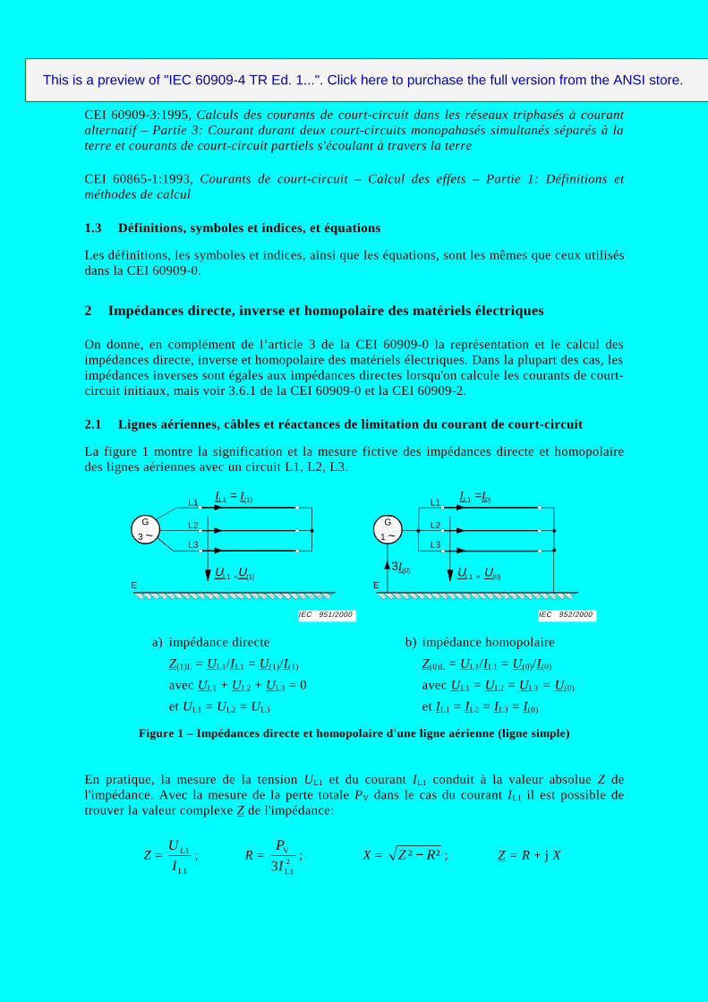
2.1 Lignes aériennes, câbles et réactances de limitation du courant de court-circuit
La figure 1 montre la signification et la mesure fictive des impédances directe et homopolairedes lignes aériennes avec un circuit L1, L2, L3.
avec UL1 + UL2 + UL3 = 0 avec UL1 = UL2 = UL3 = U (0)
et UL1 = UL2 = UL3 et IL1 = IL2 = IL3 = I (0)
Figure 1 – Impédances directe et homopolaire d'une ligne aérienne (ligne simple)
En pratique, la mesure de la tension UL1 et du courant IL1 conduit à la valeur absolue Z del'impédance. Avec la mesure de la perte totale PV dans le cas du courant IL1 il est possible detrouver la valeur complexe Z de l'impédance:
Z = L1
L1
I
U; R =
2L1
V
3I
P; X = ²² RZ − ; Z = R + j X
L1
L2
L3
IL1 = I(1)
UL1 =U(1)
G
3 ~
E
L1
L2
L3
IL1 =I0)
UL1 = U(0)
G
1 ~
E
3I(0)
IEC 952/2000IEC 951/2000
This is a preview of "IEC 60909-4 TR Ed. 1...". Click here to purchase the full version from the ANSI store.
IEC 60909-3:1995, Short-circuit currents in three-phase a.c. systems – Part 3: Currents duringtwo separate simultaneous single phase line-to-earth short circuits and partial short-circuitcurrents flowing through earth
IEC 60865-1:1993, Short-circuit currents – Calculation of effects – Part 1: Definitions andcalculation methods
1.3 Definitions, symbols and indices, and equations
The definitions, symbols, indices and the equations are the same as those used in IEC 60909-0.
2 Positive-sequence, negative-sequence and zero-sequence impedances ofelectrical equipment
In addition to clause 3 of IEC 60909-0, modelling and calculation of the positive-sequence andthe zero-sequence impedances of electrical equipment is given. In most cases the negative-sequence impedances are equal to the positive-sequence impedances when calculating the initialshort-circuit currents, but see 3.6.1 of IEC 60909-0 and IEC 60909-2.
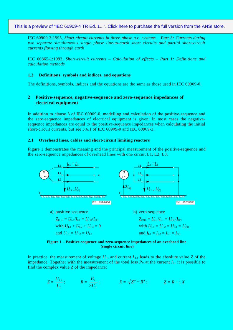
2.1 Overhead lines, cables and short-circuit limiting reactors
Figure 1 demonstrates the meaning and the principal measurement of the positive-sequence andthe zero-sequence impedances of overhead lines with one circuit L1, L2, L3.
with UL1 + UL2 + UL3 = 0 with UL1 = UL2 = UL3 = U (0)
and UL1 = UL2 = UL3 and IL1 = IL2 = IL3 = I (0)
Figure 1 – Positive-sequence and zero-sequence impedances of an overhead line (single circuit line)
In practice, the measurement of voltage UL1 and current I L1 leads to the absolute value Z of theimpedance. Together with the measurement of the total loss PV at the current IL1 it is possible tofind the complex value Z of the impedance:
Z = L1
L1
I
U; R =
2L1
V
3I
P; X = ²² RZ − ; Z = R + j X
L1
L2
L3
IL1 = I(1)
UL1 =U(1)
G
3 ~
E
L1
L2
L3
IL1 =I0)
UL1 = U(0)
G
1 ~
E
3I(0)
IEC 952/2000IEC 951/2000
This is a preview of "IEC 60909-4 TR Ed. 1...". Click here to purchase the full version from the ANSI store.
3.3.2 Lignes (câbles et lignes aériennes).................................................................42
3.4 Calcul de "kI et ip pour les court circuits triphasés .....................................................44
3.4.1 Point de court-circuit F1 ................................................................................44
3.4.2 Point de court-circuit F2 ................................................................................46
3.4.3 Point de court-circuit F3 ................................................................................48
3.5 Calcul de "k1I et ip1 pour les courts-circuits phase terre ..............................................48
3.5.1 Point de court-circuit F1 ................................................................................48
3.5.2 Point de court-circuit F2 ................................................................................52
3.5.3 Point de court-circuit F3 ................................................................................54
3.6 Récapitulation des résultats........................................................................................54
4 Calcul des courants de court-circuit triphasés dans un réseau moyenne tension – influencedes moteurs .........................................................................................................................56
1.3 Definitions, symbols and indices, and equations ........................................................13
2 Positive-sequence, negative-sequence and zero-sequence impedances of electricalequipment............................................................................................................................13
2.1 Overhead lines, cables and short-circuit limiting reactors ..........................................13
3.6 Collection of results...................................................................................................55
4 Calculation of three-phase short-circuit currents in a medium-voltage system –influence of motors..............................................................................................................57
4.1 Problem .....................................................................................................................57
4.2 Complex calculation with absolute quantities ............................................................59
4.3 Calculation with short-circuit reactances of electrical equipment ..............................67
4.4 Calculation with per-unit quantities ...........................................................................71
4.5 Calculation with the superposition method ................................................................75
This is a preview of "IEC 60909-4 TR Ed. 1...". Click here to purchase the full version from the ANSI store.
5 Calcul des courants de court-circuit triphasés pour un groupe de production etle réseau auxiliaire ..............................................................................................................82
5.3 Calcul des courants de court-circuit ...........................................................................98
5.3.1 Point de court-circuit F1 ................................................................................98
5.3.2 Point de court-circuit F2 .............................................................................. 100
5.3.3 Point de court-circuit F3 .............................................................................. 104
5.3.4 Point de court-circuit F4 .............................................................................. 110
5.3.5 Point de court-circuit F5 .............................................................................. 114
6 Réseau d'essai pour le calcul des courants de court-circuit avec des programmesinformatiques, conformément à la CEI 60909-0................................................................. 118
5 Calculation of three-phase short-circuit currents for a power station unit andthe auxiliary network...........................................................................................................83
5.1 Problem .....................................................................................................................83
5.2 Short-circuit impedances of electrical equipment.......................................................87
6 Test network for the calculation of short-circuit currents with digital programsin accordance with IEC 60909-0........................................................................................ 119
6.1 General .................................................................................................................... 119
6.2 High-voltage test network 380 kV/ 110 kV/30 kV.................................................... 121
6.2.1 Network topology and data .......................................................................... 121
6.2.2 Short-circuit impedances of electrical equipment ........................................ 125
COURANTS DE COURT-CIRCUIT DANS LES RÉSEAUX TRIPHASÉS ÀCOURANT ALTERNATIF –
Partie 4: Exemples pour le calcul des courants de court-circuit
AVANT-PROPOS
1) La CEI (Commission Électrotechnique Internationale) est une organisation mondiale de normalisation composéede l'ensemble des comités électrotechniques nationaux (Comités nationaux de la CEI). La CEI a pour objet defavoriser la coopération internationale pour toutes les questions de normalisation dans les domaines del'électricité et de l'électronique. A cet effet, la CEI, entre autres activités, publie des Normes internationales. Leurélaboration est confiée à des comités d'études, aux travaux desquels tout Comité national intéressé par le sujettraité peut participer. Les organisations internationales, gouvernementales et non gouvernementales, en liaisonavec la CEI, participent également aux travaux. La CEI collabore étroitement avec l'Organisation Internationalede Normalisation (ISO), selon des conditions fixées par accord entre les deux organisations.
2) Les décisions ou accords officiels de la CEI concernant les questions techniques représentent, dans la mesure dupossible, un accord international sur les sujets étudiés, étant donné que les Comités nationaux intéressés sontreprésentés dans chaque comité d’études.
3) Les documents produits se présentent sous la forme de recommandations internationales. Ils sont publiés commenormes, spécifications techniques, rapports techniques ou guides et agréés comme tels par les Comités nationaux.
4) Dans le but d'encourager l'unification internationale, les Comités nationaux de la CEI s'engagent à appliquer defaçon transparente, dans toute la mesure possible, les Normes internationales de la CEI dans leurs normesnationales et régionales. Toute divergence entre la norme de la CEI et la norme nationale ou régionalecorrespondante doit être indiquée en termes clairs dans cette dernière.
5) La CEI n’a fixé aucune procédure concernant le marquage comme indication d’approbation et sa responsabilitén’est pas engagée quand un matériel est déclaré conforme à l’une de ses normes.
6) L’attention est attirée sur le fait que certains des éléments du présent rapport technique peuvent faire l’objet dedroits de propriété intellectuelle ou de droits analogues. La CEI ne saurait être tenue pour responsable de ne pasavoir identifié de tels droits de propriété et de ne pas avoir signalé leur existence.
La tâche principale des comités d’études de la CEI est l’élaboration des Normes internationales.Toutefois, un comité d’études peut proposer la publication d’un rapport technique lorsqu’il a réunides données de nature différente de celles qui sont normalement publiées comme Normesinternationales, cela pouvant comprendre, par exemple, des informations sur l’état de la technique.
La CEI 60909-4, qui est un rapport technique, a été établie par le comité d’études 73 de la CEI:Courants de court-circuit.
Ce rapport technique doit être utilisé conjointement avec la CEI 60909-0.
Le texte de ce rapport technique est issu des documents suivants:
Projet d’enquête Rapport de vote
73/105/CDV 73/108/RVC
Le rapport de vote indiqué dans le tableau ci-dessus donne toute information sur le vote ayantabouti à l'approbation de ce rapport technique.
Cette publication a été rédigée selon les Directives ISO/CEI, Partie 3.
Ce document, purement informatif, ne doit pas être considéré comme une Norme internationale.
This is a preview of "IEC 60909-4 TR Ed. 1...". Click here to purchase the full version from the ANSI store.
INTERNATIONAL ELECTROTECHNICAL COMMISSION____________
SHORT-CIRCUIT CURRENTS IN THREE-PHASE AC SYSTEMS –
Part 4: Examples for the calculation of short-circuit currents
FOREWORD
1) The IEC (International Electrotechnical Commission) is a worldwide organization for standardization comprisingall national electrotechnical committees (IEC National Committees). The object of the IEC is to promoteinternational co-operation on all questions concerning standardization in the electrical and electronic fields. Tothis end and in addition to other activities, the IEC publishes International Standards. Their preparation isentrusted to technical committees; any IEC National Committee interested in the subject dealt with mayparticipate in this preparatory work. International, governmental and non-governmental organizations liaisingwith the IEC also participate in this preparation. The IEC collaborates closely with the International Organizationfor Standardization (ISO) in accordance with conditions determined by agreement between the two organizations.
2) The formal decisions or agreements of the IEC on technical matters express, as nearly as possible, an internationalconsensus of opinion on the relevant subjects since each technical committee has representation from allinterested National Committees.
3) The documents produced have the form of recommendations for international use and are published in the form ofstandards, technical specifications, technical reports or guides and they are accepted by the National Committeesin that sense.
4) In order to promote international unification, IEC National Committees undertake to apply IEC InternationalStandards transparently to the maximum extent possible in their national and regional standards. Any divergencebetween the IEC Standard and the corresponding national or regional standard shall be clearly indicated in thelatter.
5) The IEC provides no marking procedure to indicate its approval and cannot be rendered responsible for anyequipment declared to be in conformity with one of its standards.
6) Attention is drawn to the possibility that some of the elements of this technical report may be the subject of patentrights. The IEC shall not be held responsible for identifying any or all such patent rights.
The main task of IEC technical committees is to prepare International Standards. However, atechnical committee may propose the publication of a technical report when it has collected dataof a different kind from that which is normally published as an International Standard, forexample "state of the art".
IEC 60909-4, which is a technical report, has been prepared by IEC technical committee 73:Short-circuit currents.
This technical report shall be used in conjunction with IEC 60909-0.
The text of this technical report is based on the following documents:
Enquiry draft Report on voting
73/105/CDV 73/108/RVC
Full information on the voting for the approval of this technical report can be found in the reporton voting indicated in the above table.
This publication has been drafted in accordance with the ISO/IEC Directives, Part 3.
This document, which is purely informative, is not to be regarded as an International Standard.
This is a preview of "IEC 60909-4 TR Ed. 1...". Click here to purchase the full version from the ANSI store.
COURANTS DE COURT-CIRCUIT DANS LES RÉSEAUX TRIPHASÉSÀ COURANT ALTERNATIF –
Partie 4: Exemples pour le calcul des courants de court-circuit
1 Généralités
1.1 Domaine d'application et objet
La présente partie de la CEI 60909 est un rapport technique destiné à fournir une aide àl'application de la CEI 60909-0 pour le calcul des courants de court-circuit dans les réseauxtriphasés à courant alternatif 50 Hz ou 60 Hz.
Le présent rapport technique ne donne aucune prescription complémentaire mais constitue unsupport pour la représentation des matériels électriques dans un système direct, inverse ethomopolaire (article 2) et la réalisation pratique des calculs dans un réseau à basse tension(article 3), un réseau à moyenne tension avec moteurs asynchrones (article 4) et un groupe deproduction avec son réseau auxiliaire alimentant un nombre important de moteurs asynchrones àmoyenne tension et de groupes de moteurs à basse tension (article 5).
Les trois exemples donnés aux articles 3, 4 et 5 sont similaires à ceux donnés dans la CEI 60909(1988) mais ils ont été révisés conformément à la CEI 60909-0, qui la remplace.
Un paragraphe a été ajouté à l'exemple de l'article 3 pour donner une comparaison entre lesrésultats trouvés avec l'application de la source de tension équivalente au point de court-circuitselon la procédure donnée dans la CEI 60909-0 d'une part, et les résultats trouvés avec laméthode par superposition d'autre part, qui tiennent compte des différentes conditions de flux depuissance avant le court-circuit.
L'article 6 du présent rapport technique donne le schéma de circuit et les caractéristiques d'unréseau d'essai ainsi que les résultats pour un calcul effectué conformément à la CEI 60909-0,pour permettre la comparaison entre les résultats trouvés avec un programme informatique pour
le calcul des courants de court-circuit et les résultats donnés pour p1k1kbpk et,,,, iIIIiI ″″ dans
un réseau haute tension avec des groupes de production, des alternateurs, des moteurs asynchrones etdes lignes avec quatre niveaux de tension différents: 380 kV, 110 kV, 30 kV et 10 kV.
1.2 Documents de référence
CEI 60038:1983, Tensions normales de la CEI
CEI 60909-0:2000, Courants de court-circuit dans les réseaux triphasés à courant alternatif –Partie 0: Calcul des courants
CEI 60909-1:1991, Calculs des courants de court-circuit dans les réseaux triphasés à courantalternatif – Partie 1: Facteurs pour le calcul des courants de court-circuit dans les réseauxalternatifs triphasés conformément à la CEI 60909
CEI 60909-2:1992, Matériel électrique – Données pour le calcul des courants de court-circuit conformément à la CEI 60909
This is a preview of "IEC 60909-4 TR Ed. 1...". Click here to purchase the full version from the ANSI store.
SHORT-CIRCUIT CURRENTS IN THREE-PHASE AC SYSTEMS –
Part 4: Examples for the calculation of short-circuit currents
1 General
1.1 Scope and object
This part of IEC 60909 is a technical report intended to give help for the application ofIEC 60909-0 for the calculation of short-circuit currents in 50 Hz or 60 Hz three-phase a.c.systems.
This technical report does not include additional requirements but gives support for themodelling of electrical equipment in the positive-sequence, the negative-sequence and the zero-sequence system (clause 2) and the practical execution of calculations in a low-voltage system(clause 3), a medium-voltage system with asynchronous motors (clause 4) and a power-stationunit with its auxiliary network feeding a large number of medium-voltage asynchronous motorsand low-voltage motor groups (clause 5).
The three examples given in clauses 3, 4 and 5 are similar to those given in IEC 60909 (1988)but they are revised in accordance with IEC 60909-0, which replaces it.
A subclause is added to the example in clause 3 to give a comparison between the results foundwith the application of the equivalent voltage source at the short-circuit location following theprocedure given in IEC 60909-0 on the one hand, and results found with the superpositionmethod on the other hand, taking into account different load-flow conditions before the shortcircuit.
Clause 6 of this technical report gives the circuit diagram and the data of a test network and theresults for a calculation carried out in accordance with IEC 60909-0, to offer the possibility for acomparison between the results found with a digital program for the calculation of short-circuit
currents and the given results for p1k1kbpk and,,,, iIIIiI ″″ in a high-voltage network with
power-station units, generators, asynchronous motors and lines in four different voltage levels380 kV, 110 kV, 30 kV and 10 kV.
1.2 Reference documents
IEC 60038:1983, IEC Standard voltages
IEC 60909-0:2000, Short-circuit currents in three-phase a.c. systems – Part 0: Calculation ofcurrents
IEC 60909-1:1991, Short-circuit current calculation in three-phase a.c. systems – Part 1:Factors for the calculation of short-circuit currents in three-phase a.c. systems according toIEC 60909
IEC 60909-2:1992, Electrical equipment – Data for short-circuit current calculations inaccordance with IEC 60909
This is a preview of "IEC 60909-4 TR Ed. 1...". Click here to purchase the full version from the ANSI store.
CEI 60909-3:1995, Calculs des courants de court-circuit dans les réseaux triphasés à courantalternatif – Partie 3: Courant durant deux court-circuits monopahasés simultanés séparés à laterre et courants de court-circuit partiels s'écoulant à travers la terre
CEI 60865-1:1993, Courants de court-circuit – Calcul des effets – Partie 1: Définitions etméthodes de calcul
1.3 Définitions, symboles et indices, et équations
Les définitions, les symboles et indices, ainsi que les équations, sont les mêmes que ceux utilisésdans la CEI 60909-0.
2 Impédances directe, inverse et homopolaire des matériels électriques
On donne, en complément de l’article 3 de la CEI 60909-0 la représentation et le calcul desimpédances directe, inverse et homopolaire des matériels électriques. Dans la plupart des cas, lesimpédances inverses sont égales aux impédances directes lorsqu'on calcule les courants de court-circuit initiaux, mais voir 3.6.1 de la CEI 60909-0 et la CEI 60909-2.
2.1 Lignes aériennes, câbles et réactances de limitation du courant de court-circuit
La figure 1 montre la signification et la mesure fictive des impédances directe et homopolairedes lignes aériennes avec un circuit L1, L2, L3.
avec UL1 + UL2 + UL3 = 0 avec UL1 = UL2 = UL3 = U (0)
et UL1 = UL2 = UL3 et IL1 = IL2 = IL3 = I (0)
Figure 1 – Impédances directe et homopolaire d'une ligne aérienne (ligne simple)
En pratique, la mesure de la tension UL1 et du courant IL1 conduit à la valeur absolue Z del'impédance. Avec la mesure de la perte totale PV dans le cas du courant IL1 il est possible detrouver la valeur complexe Z de l'impédance:
Z = L1
L1
I
U; R =
2L1
V
3I
P; X = ²² RZ − ; Z = R + j X
L1
L2
L3
IL1 = I(1)
UL1 =U(1)
G
3 ~
E
L1
L2
L3
IL1 =I0)
UL1 = U(0)
G
1 ~
E
3I(0)
IEC 952/2000IEC 951/2000
This is a preview of "IEC 60909-4 TR Ed. 1...". Click here to purchase the full version from the ANSI store.
IEC 60909-3:1995, Short-circuit currents in three-phase a.c. systems – Part 3: Currents duringtwo separate simultaneous single phase line-to-earth short circuits and partial short-circuitcurrents flowing through earth
IEC 60865-1:1993, Short-circuit currents – Calculation of effects – Part 1: Definitions andcalculation methods
1.3 Definitions, symbols and indices, and equations
The definitions, symbols, indices and the equations are the same as those used in IEC 60909-0.
2 Positive-sequence, negative-sequence and zero-sequence impedances ofelectrical equipment
In addition to clause 3 of IEC 60909-0, modelling and calculation of the positive-sequence andthe zero-sequence impedances of electrical equipment is given. In most cases the negative-sequence impedances are equal to the positive-sequence impedances when calculating the initialshort-circuit currents, but see 3.6.1 of IEC 60909-0 and IEC 60909-2.
2.1 Overhead lines, cables and short-circuit limiting reactors
Figure 1 demonstrates the meaning and the principal measurement of the positive-sequence andthe zero-sequence impedances of overhead lines with one circuit L1, L2, L3.
with UL1 + UL2 + UL3 = 0 with UL1 = UL2 = UL3 = U (0)
and UL1 = UL2 = UL3 and IL1 = IL2 = IL3 = I (0)
Figure 1 – Positive-sequence and zero-sequence impedances of an overhead line (single circuit line)
In practice, the measurement of voltage UL1 and current I L1 leads to the absolute value Z of theimpedance. Together with the measurement of the total loss PV at the current IL1 it is possible tofind the complex value Z of the impedance:
Z = L1
L1
I
U; R =
2L1
V
3I
P; X = ²² RZ − ; Z = R + j X
L1
L2
L3
IL1 = I(1)
UL1 =U(1)
G
3 ~
E
L1
L2
L3
IL1 =I0)
UL1 = U(0)
G
1 ~
E
3I(0)
IEC 952/2000IEC 951/2000
This is a preview of "IEC 60909-4 TR Ed. 1...". Click here to purchase the full version from the ANSI store.