1 INTRODUCTION CONTENTS WARNING This radio controlled helicopter is not a toy. It is a sophisticated piece of equipment and is designed for hobby use only. If not properly assembled and operated, it is capable of causing property damage and bodily harm to both the operator and/or spectators. Thunder Tiger and its duly authorized distributors assume no liability for damage that could occur from the assembly and/or use/misuse of this product. AMA INFORMATION Operating a model helicopter requires a high degree of diligence and skill. If you are a newcomer to the hobby, it is best to seek help and guidance from accomplished model helicopter pilots. This will greatly speed up the learning process and have you flying successfully in a reasonable time. We also would strongly urge you to join the Academy of Model Aeronautics. The AMA is a non-profit organization that provides its members Congratulations on your purchase of the Raptor 30 V2 helicopter. This model was designed and engineered by the World-renowned Mr. Shigetada Taya. It combines elements of his previously successful designs with today's advanced technologies. Since the introduction of the original Raptor 30 in 1998, many have been sold around the world. It is the most popular 30-size helicopter in the world. The Raptor 30 has helped beginners master the art of RC helicopter flying. The Raptor 30 has helped experienced pilots learn new 3-D maneuvers. This is truly a versatile model helicopter for everyone. We did not just sat on our laurel, our team of engineers and test pilots have collected feedbacks from around the world and have now made the Raptor 30 an even better helicopter. We made new molds and tooling for new parts. Many area have subtle changes to increase strength and durability. As one of the largest R/C manufacturers in the world, Thunder Tiger has spared no expense to bring you this incredible new machine. All production parts are manufactured by use of the most modern technology available and meets or exceeds the standards as set forth by ISO-9001. In the last few years we have spend time and resource to develop a new Thunder Tiger PRO- 39H(R) ring engine for the Raptor 30 V2 and for other 30-size helicopters. The new PRO-39H(R) has much better transition characteristics than the Pro 36H ABC engine. The needles are easy to set. The ring design eliminates the criticalness of ABC engines. You will find the new 39H engine produce more power than any other available 30-size engines. Together, the new Raptor 30 V2 and the PRO 39H(R) engine will provide you with many hours of enjoyment. Thank you again for purchasing our fine products. Introduction......................................... p.1 Contents.............................................. p.1 Warnings............................................. p.1 Additional Items Needed..................... p.3 Tools Needed...................................... p.3 Assembling Section............................ p.4 Flight Training Section........................ p.22 Maintenance Section.......................... p.30 Blade Modification............................. p.35
Transcript
1
INTRODUCTION
CONTENTS
WARNINGThis radio controlled helicopter is not a toy. It is a sophisticated piece of equipment and
is designed for hobby use only. If not properly assembled and operated, it is capable of
causing property damage and bodily harm to both the operator and/or spectators. Thunder
Tiger and its duly authorized distributors assume no liability for damage that could occur
from the assembly and/or use/misuse of this product.
AMA INFORMATIONOperating a model helicopter requires a high degree of diligence and skill. If you are a
newcomer to the hobby, it is best to seek help and guidance from accomplished model
helicopter pilots. This will greatly speed up the learning process and have you flying
successfully in a reasonable time. We also would strongly urge you to join the Academy
of Model Aeronautics. The AMA is a non-profit organization that provides its members
Congratulations on your purchase of the Raptor 30 V2 helicopter. This model was designed andengineered by the World-renowned Mr. Shigetada Taya. It combines elements of his previouslysuccessful designs with today's advanced technologies. Since the introduction of the originalRaptor 30 in 1998, many have been sold around the world. It is the most popular 30-size helicopterin the world. The Raptor 30 has helped beginners master the art of RC helicopter flying. TheRaptor 30 has helped experienced pilots learn new 3-D maneuvers. This is truly a versatile modelhelicopter for everyone. We did not just sat on our laurel, our team of engineers and test pilotshave collected feedbacks from around the world and have now made the Raptor 30 an even betterhelicopter. We made new molds and tooling for new parts. Many area have subtle changes toincrease strength and durability.As one of the largest R/C manufacturers in the world, Thunder Tiger has spared no expense tobring you this incredible new machine. All production parts are manufactured by use of the mostmodern technology available and meets or exceeds the standards as set forth by ISO-9001.In the last few years we have spend time and resource to develop a new Thunder Tiger PRO-39H(R) ring engine for the Raptor 30 V2 and for other 30-size helicopters. The new PRO-39H(R)has much better transition characteristics than the Pro 36H ABC engine. The needles are easyto set. The ring design eliminates the criticalness of ABC engines. You will find the new 39Hengine produce more power than any other available 30-size engines. Together, the new Raptor30 V2 and the PRO 39H(R) engine will provide you with many hours of enjoyment. Thank youagain for purchasing our fine products.
with a liability insurance plan as well as monthly magazine entitled Model Aviation. All
AMA charter aircraft clubs require all pilots to hold a current AMA sporting license prior
to operation of their models at club fields. For further information, contact the AMA at:Academy of Model Aeronautics5151 East Memorial DriveMuncie, IN 47302(317) 287-1256
1. Make sure both the transmitter and receiver batteries are fully charged prior to operation thehelicopter.
2. Make sure all flight controls operate properly prior to flying.3. Range check the radio before the first flight. The servos must operate properly with the
transmitter antenna collapsed at a range of at least 50 ft.(15 meters).4. Check to make sure there is no radio interference on your radio channel before operating the
helicopter.5. Use only the recommended engine fuel as specified by the engine manufacturer.6. Make sure the transmitter and receiver are turned on before starting the engine.7. The engine throttle must be in the idle position before starting the engine.8. Model helicopter main and tail rotors operate at high RPM. Make sure nothing can come in
contact with the rotor blades during flight.9. After starting the helicopter, maintain a safe distance during the flight.10. Never operate the helicopter in rain or excessive wind conditions.11. Always operate and fly your helicopter in a safe and responsible manner.12. Never fly a model helicopter over other pilots, spectators or cars.
POST FLIGHT INSPECTION1. Inspect the model thoroughly to insure no parts have come loose or become damaged during
the flight and landing. Replace damaged parts and tighten loose screws before flying again.2. Pump out any remaining fuel from the fuel tank.3. Wipe off excess oil and fuel from helicopter body and other exposed parts.4. Lubricate all moving parts ensure smooth operation for the next time you fly.5. Store model in a cool, dry place. Avoid storage in direct sunlight or near a source of heat.
Following these few, simple safety rules will allow you to enjoy the thrill of model helicopter flyingfor many years to come.
FLIGHT SAFETY CHECKLIST
2
3
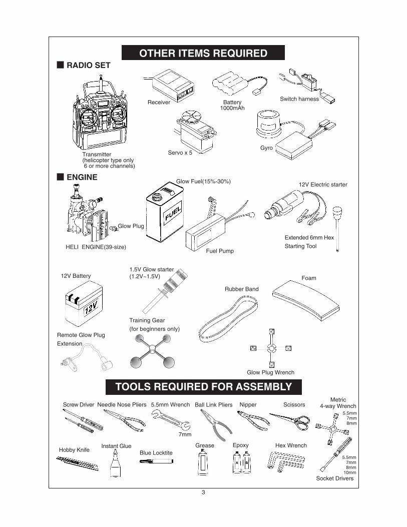
TOOLS REQUIRED FOR ASSEMBLY
OTHER ITEMS REQUIRED
Receiver
Transmitter(helicopter type only 6 or more channels)
Servo x 5
Battery1000mAh
Switch harness
Extended 6mm Hex
Starting ToolFuel Pump
HELI ENGINE(39-size)
Socket Drivers
Hex WrenchGreaseBlue Locktite
Instant GlueHobby Knife
Metric4-way WrenchScissorsNipper5.5mm WrenchNeedle Nose PliersScrew Driver
Glow Plug Wrench
Gyro
Glow Fuel(15%-30%)
12V Battery1.5V Glow starter(1.2V~1.5V)
Rubber Band
Foam
RADIO SET
ENGINE
Glow Plug
12V Electric starter
7mm
5.5mm7mm8mm
5.5mm7mm8mm
10mm
Remote Glow Plug
Extension
Epoxy
Training Gear
(for beginners only)
Ball Link Pliers
4
ASSEMBLING SECTION
The parts in the Raptor kit are packed according to the assembly steps. The part number and quantity containedin each are always shown in the square box on each page. Do not open all the bags at once. Open only the bagthat is needed for the current assembly step.
(3 )BK0463
(2 )BK0062
(5 )CB0363-1
(4 )BE1867
(1) BK0605
To Engine
(6) BB362-2
(6) BB362-2
To Muffler
5
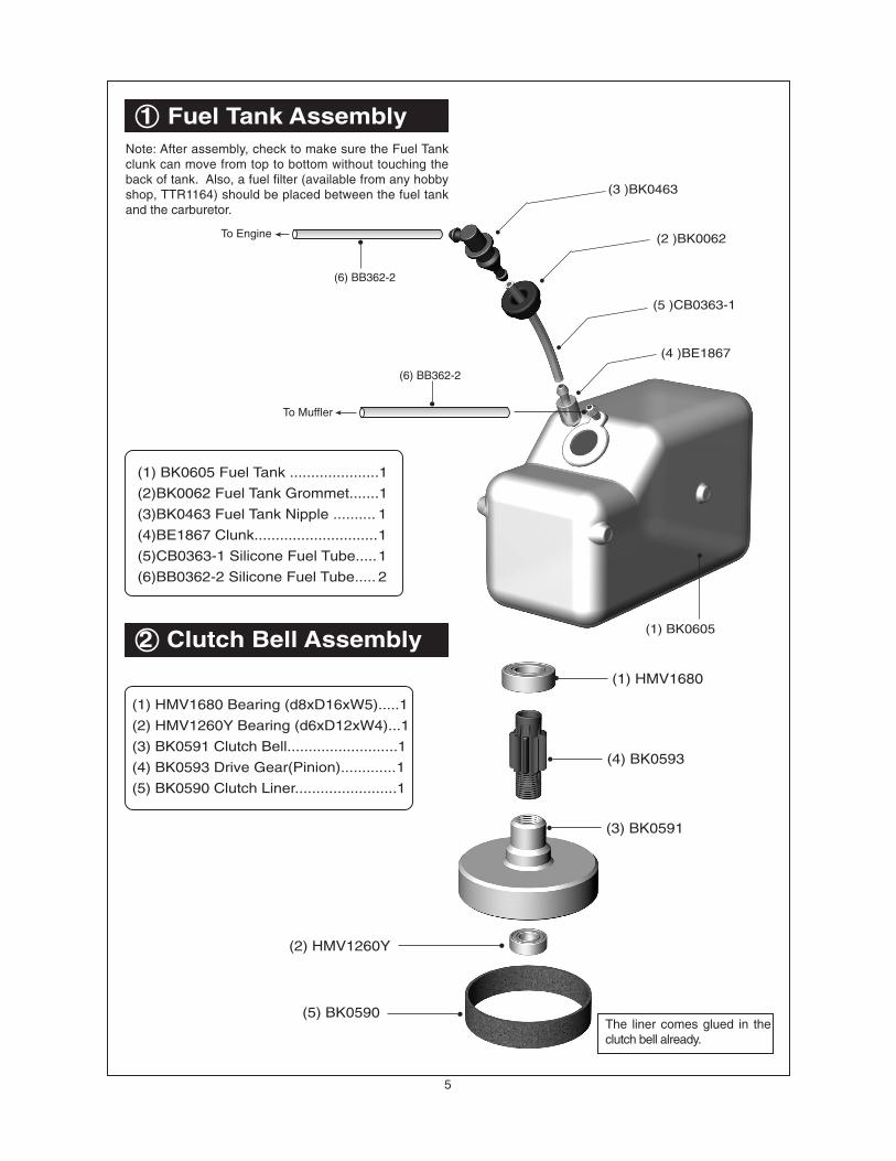
2 Clutch Bell Assembly
1 Fuel Tank Assembly
(1) BK0605 Fuel Tank .....................1
(2)BK0062 Fuel Tank Grommet.......1
(3)BK0463 Fuel Tank Nipple .......... 1
(4)BE1867 Clunk.............................1
(5)CB0363-1 Silicone Fuel Tube.....1
(6)BB0362-2 Silicone Fuel Tube..... 2
Note: After assembly, check to make sure the Fuel Tankclunk can move from top to bottom without touching theback of tank. Also, a fuel filter (available from any hobbyshop, TTR1164) should be placed between the fuel tankand the carburetor.
(1) HMV1680 Bearing (d8xD16xW5).....1
(2) HMV1260Y Bearing (d6xD12xW4)...1
(3) BK0591 Clutch Bell..........................1
(4) BK0593 Drive Gear(Pinion).............1
(5) BK0590 Clutch Liner........................1
(1) HMV1680
(4) BK0593
(3) BK0591
(2) HMV1260Y
(5) BK0590The liner comes glued in theclutch bell already.
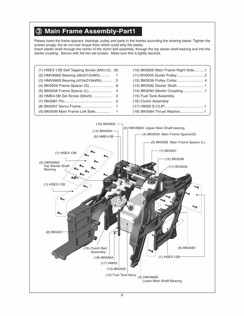
Please insert the frame spacers, bearings, pulley and parts in the frames according the drawing below. Tighten thescrews snugly, but do not over torque them which could strip the plastic.Insert starter shaft through the center of the clutch bell assembly, through the top starter shaft bearing and into thestarter coupling. Secure with the two set screws. Make sure this is tightly secured.
(17) HMS5
(18) BK0584
(3) HMV740ZZ
(4) BK0077
(5) BK0079
(6) BK0075
(7) BK0015
(8) BK0016(9) BK0014
(1) HMJ2-10N
(2) HMC3-10B
(3) HMV740ZZ(1) HMJ2-10N
(8) BK0016
(3) HMV740ZZ
(5) BK0079
(6) BK0075
(3) HMV740ZZ
(4) BK0077
(2) HMC3-10B
(7) BK0015
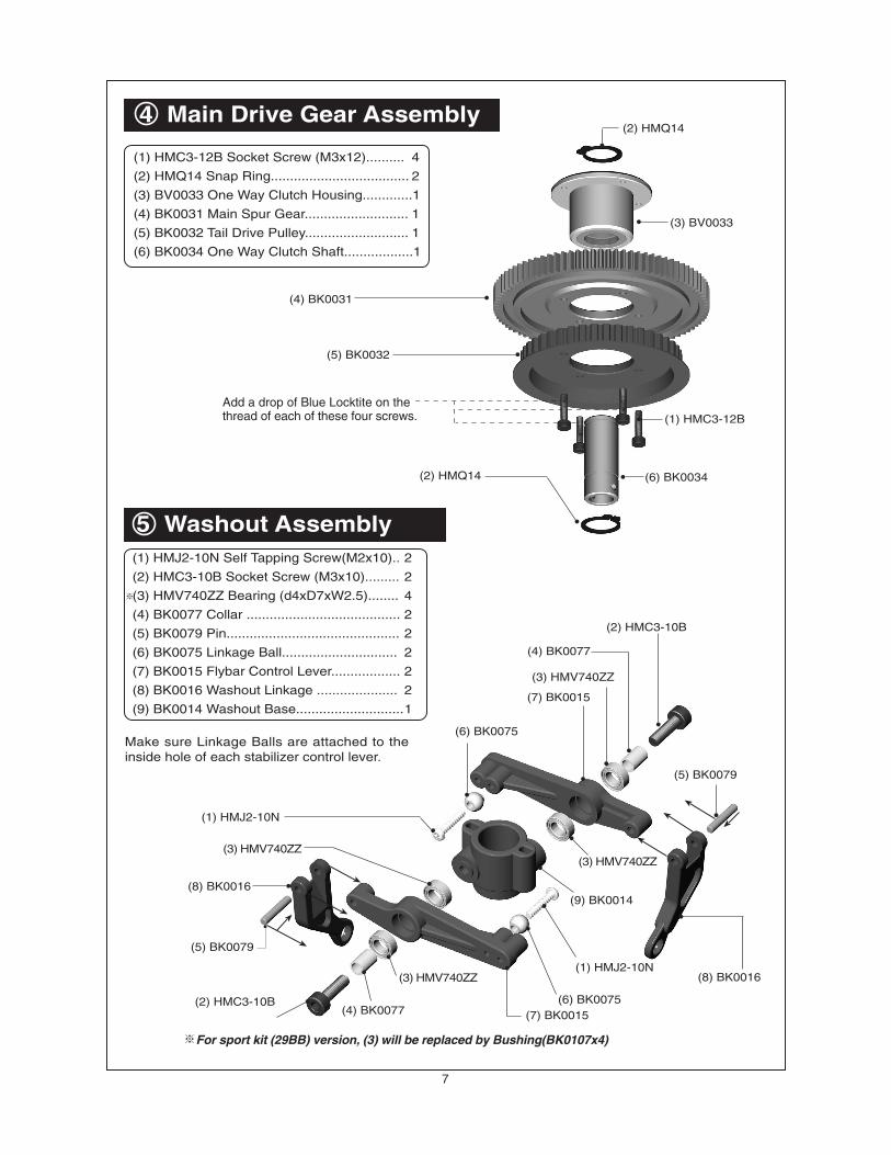
For sport kit (29BB) version, (3) will be replaced by Bushing(BK0107x4)
Make sure Linkage Balls are attached to theinside hole of each stabilizer control lever.
(1) HMC3-12B
(6) BK0034(2) HMQ14
(5) BK0032
(4) BK0031
(2) HMQ14
(3) BV0033
Add a drop of Blue Locktite on thethread of each of these four screws.
8
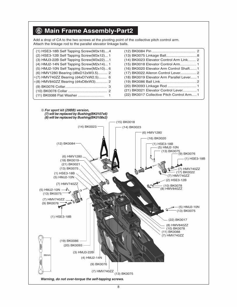
6 Main Frame Assembly-Part2Add a drop of CA to the two screws at the pivoting point of the collective pitch control arm.Attach the linkage rod to the parallel elevator linkage balls.
(1) HSE3-18B
(2) HSE3-12B
(3) HMJ3-22B
(4) HMJ2-14N
(5) HMJ2-10N
(6) HMV1280
(7) HMV740ZZ
(8) HMV840ZZ
(9) BK0076
(10) BK0078
(1) HSE3-18B(12) BK0084
(13) BK0075
(14) BK0023
(15) BK0018
(16) BK0020
(17) BK0022
(18) BK0019
(20) BK0093
(21) BK0021
(22) BK0017
(14) BK0023
(7) HMV740ZZ
(5) HMJ2-10N(13) BK0075
(8) HMV840ZZ(10) BK0078
(11) BK0088(7) HMV740ZZ
(13) BK0075(7) HMV740ZZ
(9) BK0076
(6) HMV1280
(13) BK0075
(1) HSE3-18B(5) HMJ2-10N
(7) HMV740ZZ
(5) HMJ2-10N(13) BK0075
(7) HMV740ZZ(9) BK0076
(1) HSE3-18B
(19) BK0086
For sport kit (29BB) version,(7) will be replaced by Bushing(BK0107x6)(8) will be replaced by Bushing(BK0108x2)
Warning, do not over-torque the self-tapping screws.
(12) BK0084 Pin .......................................... 2(13) BK0075 Linkage Ball..............................8(14) BK0023 Elevator Control Arm Link........ 2(15) BK0018 Elevator Control Arm................ 1(16) BK0020 Elevator Arm Control Shaft.......1(17) BK0022 Aileron Control Lever................ 2(18) BK0019 Elevator Arm Parallel Lever...... 1(19) BK0086 Ball Link....................................2(20) BK0093 Linkage Rod ............................ 1(21) BK0021 Elevator Control Lever..............1(22) BK0017 Collective Pitch Control Arm.....1
(4) BK0086 Ball Link ................................ 4
(5) BK0092 Linkage Rod ......................... 2
(6) BK0030 Main Shaft Lock Ring............ 1
(7) BK0029 Main Shaft ............................ 1
(8) Wash Out Assembly
(9) BV0601 Swash Plate Assembly...........1
(10) Main Gear Assembly
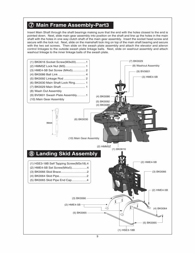
Insert Main Shaft through the shaft bearings making sure that the end with the holes closest to the end ispointed down. Next, slide main gear assembly into position on the shaft and line up the holes in the mainshaft with the holes in one way clutch shaft of the main gear assembly. Insert the socket head screw andsecure with the lock nut. Next, slide on the mainshaft lock ring on top of the main shaft bearing and securewith the two set screws. Then slide on the swash plate assembly and attach the elevator and aileroncontrol linkages to the outside swash plate linkage balls. Next, slide on washout assembly and attachwashout linkage to the inner linkage balls of the swash plate.
(3) BK0066
(2) HME4-5B
(5) BK0065
(1) HSE3-18B
(5) BK0065
(4) BK0064
(2) HME4-5B
(3) BK0066
(2) HME4-5B
(1) BK0616(2) HMM3Z
(3) HME4-5B
(6) BK0030
(7) BK0029
(9) BV0601
(10) Main Gear Assembly
(8) Washout Assembly
(4) BK0086
(5) BK0092(4) BK0086
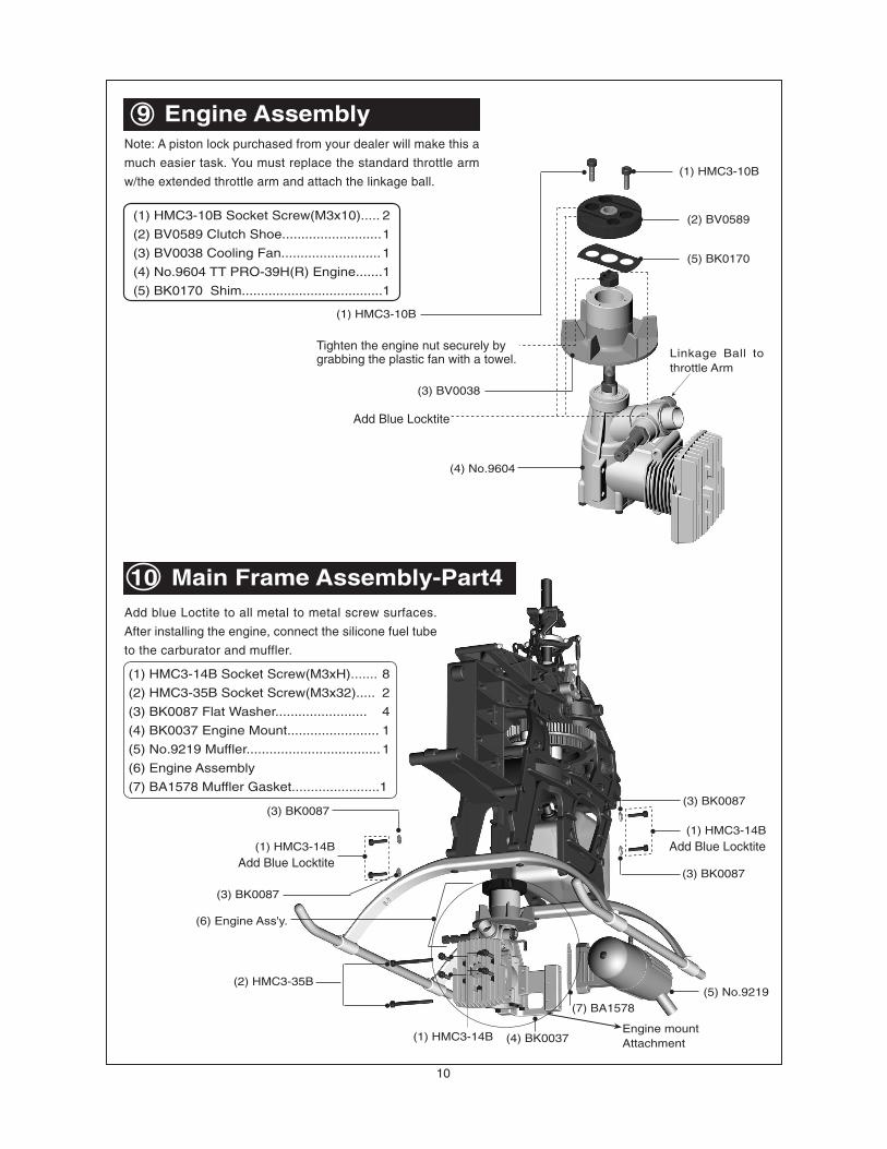
(5) No.9219
(4) BK0037
(6) Engine Ass'y.
(3) BK0087
(1) HMC3-14B
(2) HMC3-35B
(3) BK0087
Add Blue Locktite
Engine mountAttachment
(1) HMC3-14B
(1) HMC3-14B
Add Blue Locktite
(3) BK0087
(3) BK0087
10
9 Engine AssemblyNote: A piston lock purchased from your dealer will make this a
much easier task. You must replace the standard throttle arm
w/the extended throttle arm and attach the linkage ball.
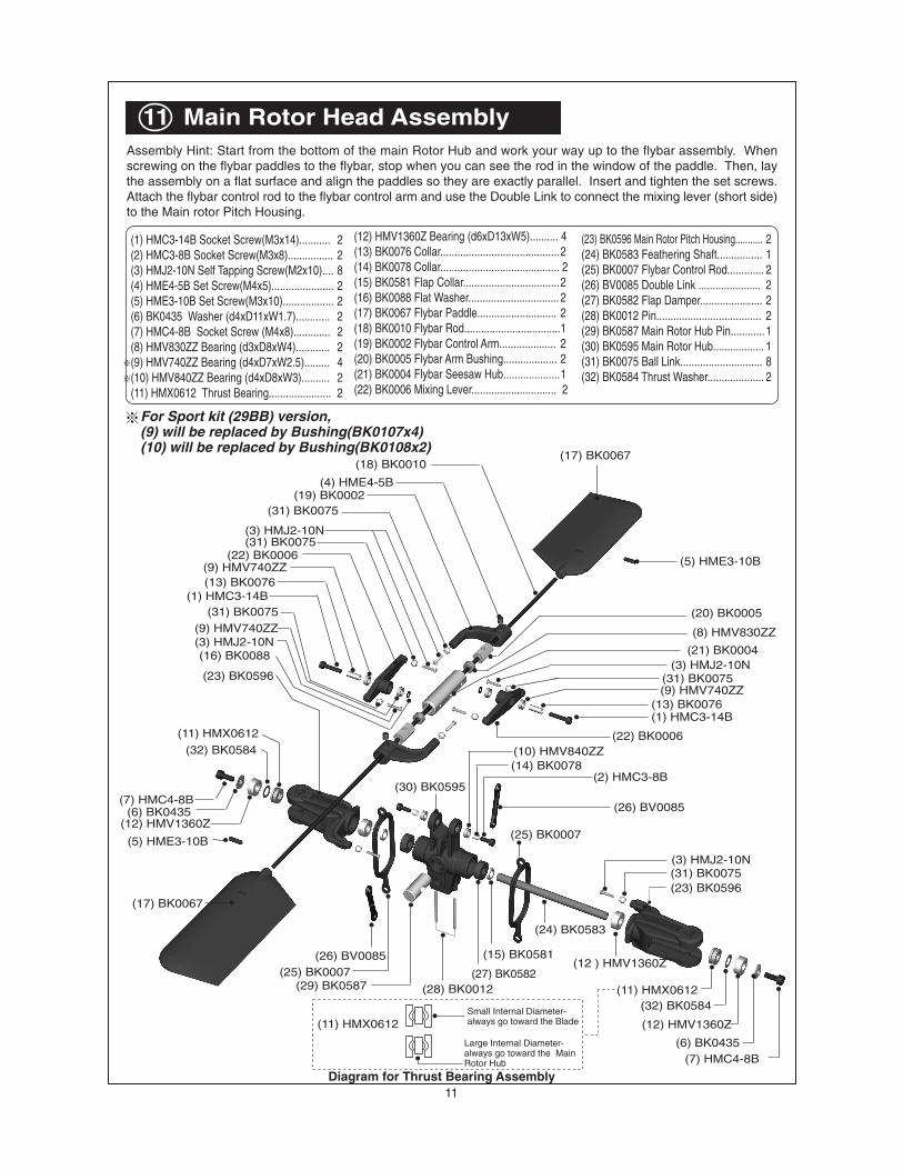
(23) BK0596 Main Rotor Pitch Housing........... 2(24) BK0583 Feathering Shaft................ 1(25) BK0007 Flybar Control Rod............. 2(26) BV0085 Double Link ...................... 2(27) BK0582 Flap Damper...................... 2(28) BK0012 Pin..................................... 2(29) BK0587 Main Rotor Hub Pin............1(30) BK0595 Main Rotor Hub.................. 1(31) BK0075 Ball Link............................. 8(32) BK0584 Thrust Washer.................... 2
Assembly Hint: Start from the bottom of the main Rotor Hub and work your way up to the flybar assembly. Whenscrewing on the flybar paddles to the flybar, stop when you can see the rod in the window of the paddle. Then, laythe assembly on a flat surface and align the paddles so they are exactly parallel. Insert and tighten the set screws.Attach the flybar control rod to the flybar control arm and use the Double Link to connect the mixing lever (short side)to the Main rotor Pitch Housing.
Diagram for Thrust Bearing Assembly
Small Internal Diameter-always go toward the Blade
Large Internal Diameter-always go toward the MainRotor Hub
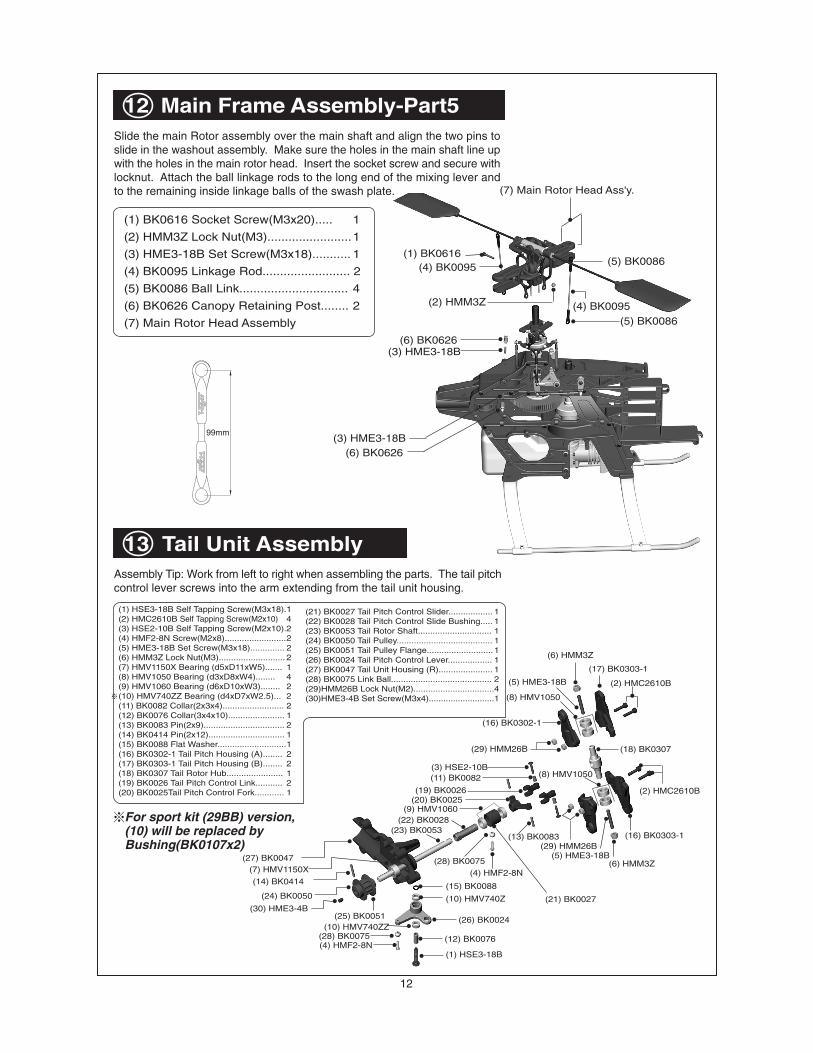
Slide the main Rotor assembly over the main shaft and align the two pins toslide in the washout assembly. Make sure the holes in the main shaft line upwith the holes in the main rotor head. Insert the socket screw and secure withlocknut. Attach the ball linkage rods to the long end of the mixing lever andto the remaining inside linkage balls of the swash plate.
Assembly Tip: Work from left to right when assembling the parts. The tail pitchcontrol lever screws into the arm extending from the tail unit housing.
For sport kit (29BB) version,(10) will be replaced byBushing(BK0107x2)
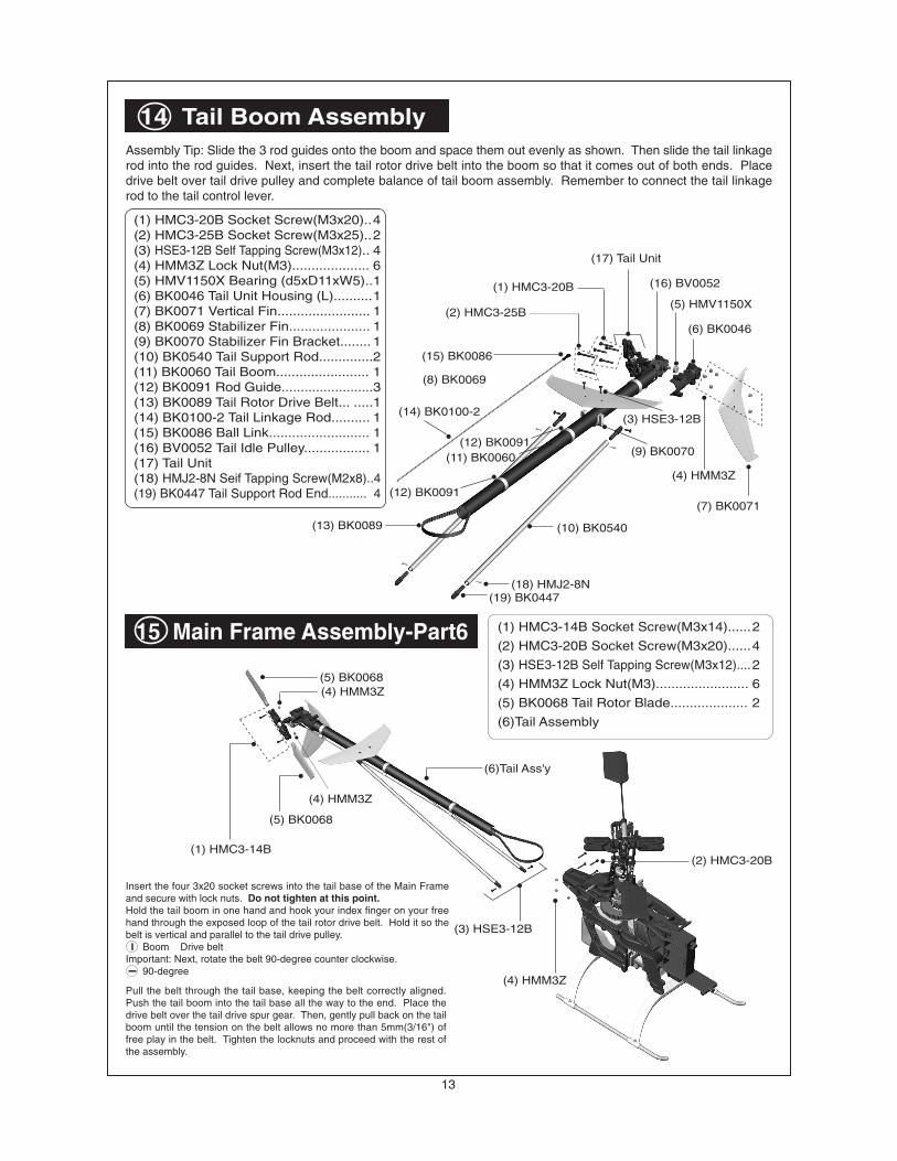
Assembly Tip: Slide the 3 rod guides onto the boom and space them out evenly as shown. Then slide the tail linkagerod into the rod guides. Next, insert the tail rotor drive belt into the boom so that it comes out of both ends. Placedrive belt over tail drive pulley and complete balance of tail boom assembly. Remember to connect the tail linkagerod to the tail control lever.
15 Main Frame Assembly-Part6 (1) HMC3-14B Socket Screw(M3x14)......2
(2) HMC3-20B Socket Screw(M3x20)......4
(3) HSE3-12B Self Tapping Screw(M3x12)....2
(4) HMM3Z Lock Nut(M3)........................ 6
(5) BK0068 Tail Rotor Blade.................... 2
(6)Tail Assembly
Pull the belt through the tail base, keeping the belt correctly aligned.Push the tail boom into the tail base all the way to the end. Place thedrive belt over the tail drive spur gear. Then, gently pull back on the tailboom until the tension on the belt allows no more than 5mm(3/16") offree play in the belt. Tighten the locknuts and proceed with the rest ofthe assembly.
Insert the four 3x20 socket screws into the tail base of the Main Frameand secure with lock nuts. Do not tighten at this point.Hold the tail boom in one hand and hook your index finger on your freehand through the exposed loop of the tail rotor drive belt. Hold it so thebelt is vertical and parallel to the tail drive pulley. Boom Drive beltImportant: Next, rotate the belt 90-degree counter clockwise. 90-degree
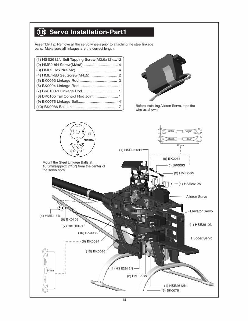
(1) HSE2612N
(9) BK0086
(5) BK0093
(2) HMF2-8N
(1) HSE2612N
(10) BK0086
(6) BK0094
(8) BK0105
(10) BK0086
(7) BK0100-1
(4) HME4-5B
(1) HSE2612N
(9) BK0075
(2) HMF2-8N
(1) HSE2612N
(1) HSE2612N
Aileron Servo
Rudder Servo
Elevator Servo
16 Servo Installation-Part1
Assembly Tip: Remove all the servo wheels prior to attaching the steel linkageballs. Make sure all linkages are the correct length.
Before installing Aileron Servo, tape thewire as shown.
84mm
72mm
Mount the Steel Linkage Balls at10.5mm(approx 7/16") from the center ofthe servo horn.
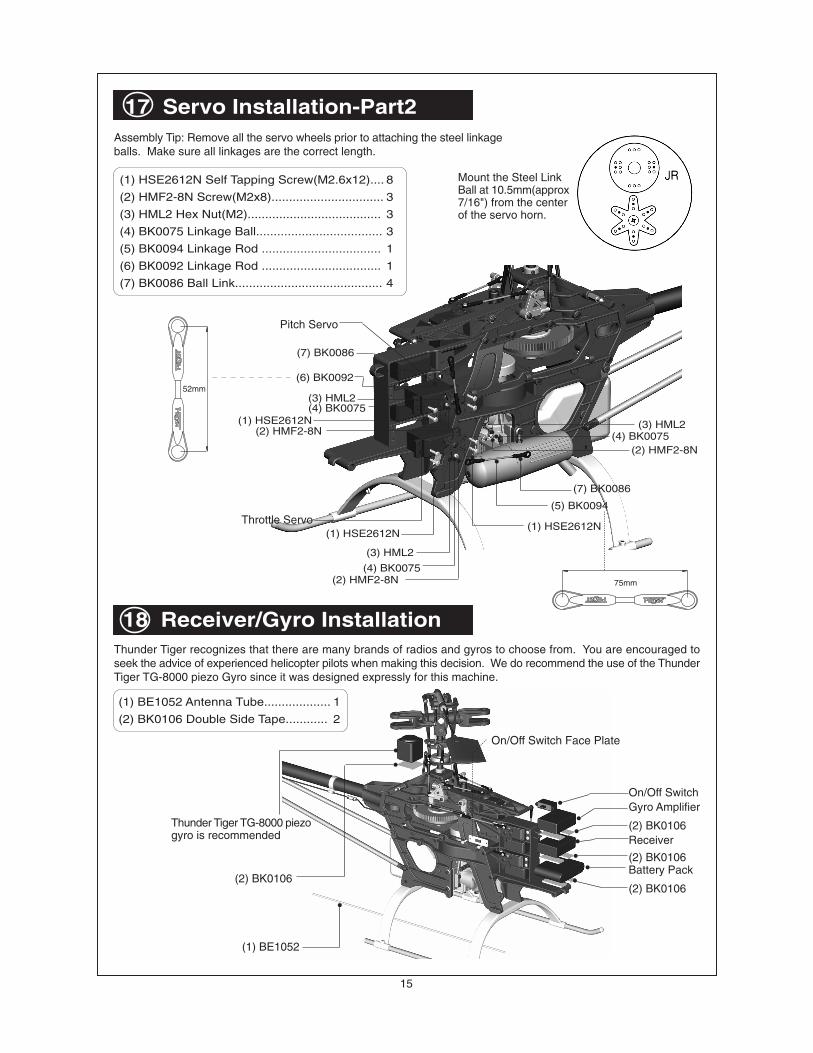
Assembly Tip: Remove all the servo wheels prior to attaching the steel linkageballs. Make sure all linkages are the correct length.
On/Off SwitchGyro Amplifier
Receiver
Battery Pack
(2) BK0106
(1) BE1052
Thunder Tiger TG-8000 piezogyro is recommended
(2) BK0106
(2) BK0106
(2) BK0106
On/Off Switch Face Plate
18 Receiver/Gyro Installation
(1) BE1052 Antenna Tube................... 1
(2) BK0106 Double Side Tape............ 2
Thunder Tiger recognizes that there are many brands of radios and gyros to choose from. You are encouraged toseek the advice of experienced helicopter pilots when making this decision. We do recommend the use of the ThunderTiger TG-8000 piezo Gyro since it was designed expressly for this machine.
16
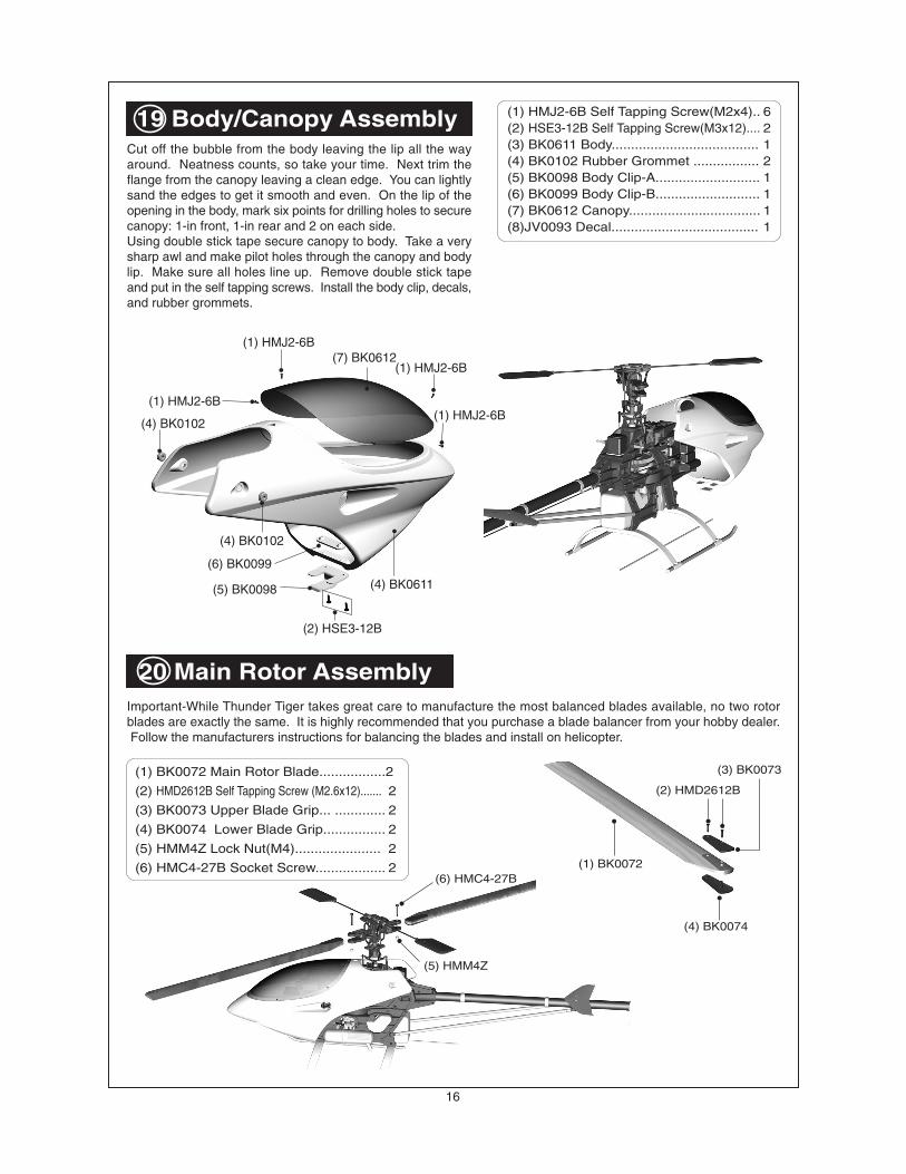
19 Body/Canopy AssemblyCut off the bubble from the body leaving the lip all the wayaround. Neatness counts, so take your time. Next trim theflange from the canopy leaving a clean edge. You can lightlysand the edges to get it smooth and even. On the lip of theopening in the body, mark six points for drilling holes to securecanopy: 1-in front, 1-in rear and 2 on each side.Using double stick tape secure canopy to body. Take a verysharp awl and make pilot holes through the canopy and bodylip. Make sure all holes line up. Remove double stick tapeand put in the self tapping screws. Install the body clip, decals,and rubber grommets.
20 Main Rotor AssemblyImportant-While Thunder Tiger takes great care to manufacture the most balanced blades available, no two rotorblades are exactly the same. It is highly recommended that you purchase a blade balancer from your hobby dealer. Follow the manufacturers instructions for balancing the blades and install on helicopter.
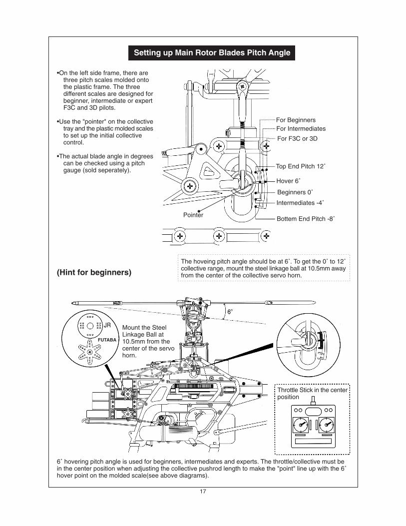
•On the left side frame, there arethree pitch scales molded ontothe plastic frame. The threedifferent scales are designed forbeginner, intermediate or expertF3C and 3D pilots.
•Use the "pointer" on the collectivetray and the plastic molded scalesto set up the initial collectivecontrol.
•The actual blade angle in degreescan be checked using a pitchgauge (sold seperately).
Setting up Main Rotor Blades Pitch Angle
The hoveing pitch angle should be at 6˚. To get the 0˚ to 12˚collective range, mount the steel linkage ball at 10.5mm awayfrom the center of the collective servo horn.
6˚ hovering pitch angle is used for beginners, intermediates and experts. The throttle/collective must bein the center position when adjusting the collective pushrod length to make the "point" line up with the 6˚hover point on the molded scale(see above diagrams).
For BeginnersFor Intermediates
For F3C or 3D
Top End Pitch 12˚
Hover 6˚
Beginners 0˚
Intermediates -4˚
Bottem End Pitch -8˚Pointer
Throttle Stick in the centerposition
Mount the SteelLinkage Ball at10.5mm from thecenter of the servohorn.
FUTABA
(Hint for beginners)
18
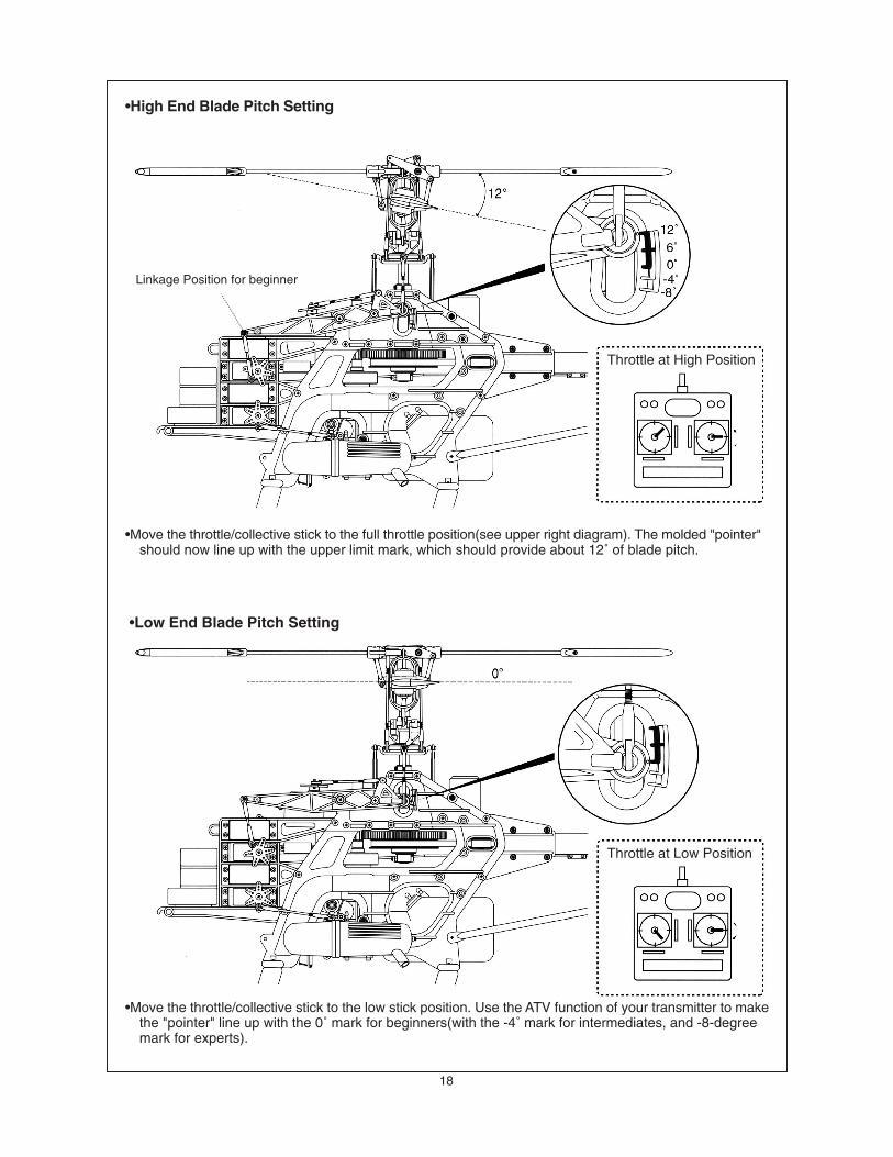
•Move the throttle/collective stick to the full throttle position(see upper right diagram). The molded "pointer"should now line up with the upper limit mark, which should provide about 12˚ of blade pitch.
•Move the throttle/collective stick to the low stick position. Use the ATV function of your transmitter to makethe "pointer" line up with the 0˚ mark for beginners(with the -4˚ mark for intermediates, and -8-degreemark for experts).
Throttle at High Position
Throttle at Low Position
•High End Blade Pitch Setting
•Low End Blade Pitch Setting
Linkage Position for beginner
19
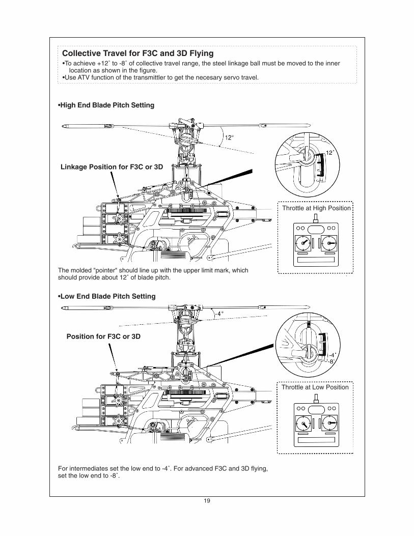
Collective Travel for F3C and 3D Flying•To achieve +12˚ to -8˚ of collective travel range, the steel linkage ball must be moved to the inner
location as shown in the figure.•Use ATV function of the transmittler to get the necesary servo travel.
The molded "pointer" should line up with the upper limit mark, whichshould provide about 12˚ of blade pitch.
For intermediates set the low end to -4˚. For advanced F3C and 3D flying,set the low end to -8˚.
Throttle at High Position
Throttle at Low Position
•High End Blade Pitch Setting
•Low End Blade Pitch Setting
Linkage Position for F3C or 3D
Position for F3C or 3D
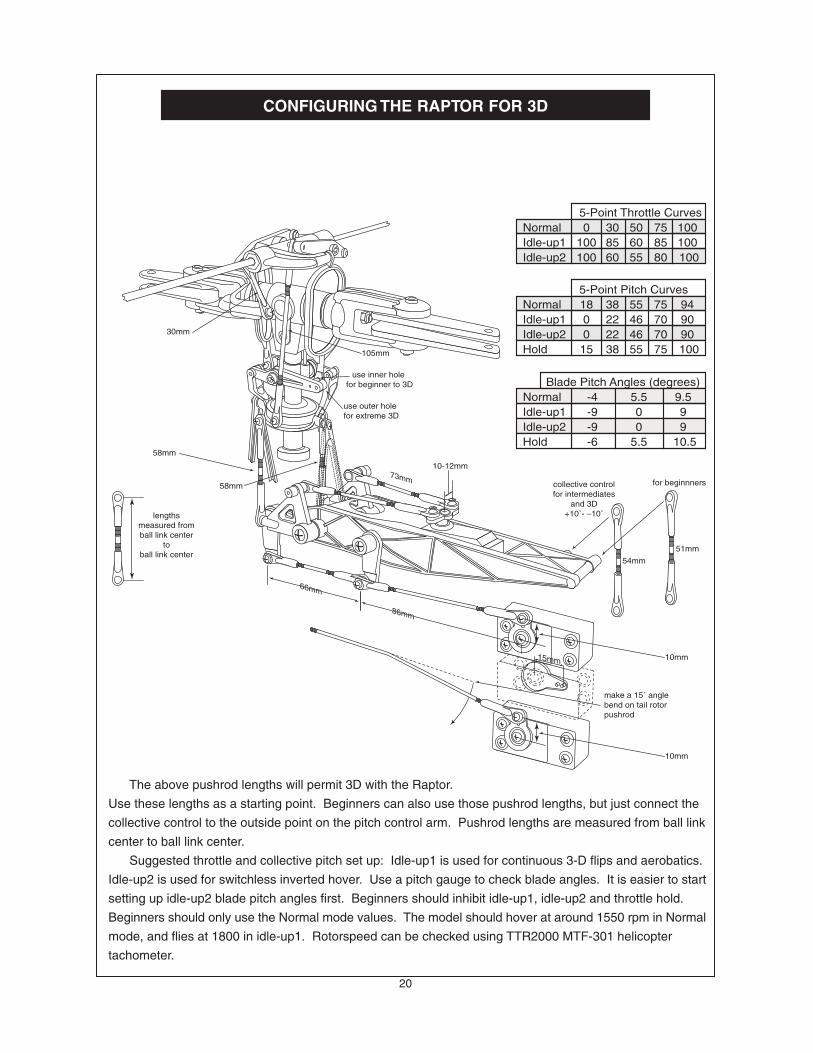
The above pushrod lengths will permit 3D with the Raptor.
Use these lengths as a starting point. Beginners can also use those pushrod lengths, but just connect the
collective control to the outside point on the pitch control arm. Pushrod lengths are measured from ball link
center to ball link center.
Suggested throttle and collective pitch set up: Idle-up1 is used for continuous 3-D flips and aerobatics.
Idle-up2 is used for switchless inverted hover. Use a pitch gauge to check blade angles. It is easier to start
setting up idle-up2 blade pitch angles first. Beginners should inhibit idle-up1, idle-up2 and throttle hold.
Beginners should only use the Normal mode values. The model should hover at around 1550 rpm in Normal
mode, and flies at 1800 in idle-up1. Rotorspeed can be checked using TTR2000 MTF-301 helicopter
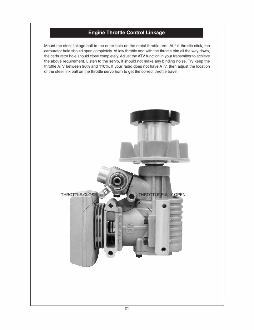
Mount the steel linkage ball to the outer hole on the metal throttle arm. At full throttle stick, thecarburetor hole should open completely. At low throttle and with the throttle trim all the way down,the carburetor hole should close completely. Adjust the ATV function in your transmitter to achievethe above requirement. Listen to the servo, it should not make any binding noise. Try keep thethrottle ATV between 90% and 110%. If your radio does not have ATV, then adjust the locationof the steel link ball on the throttle servo horn to get the correct throttle travel.
Engine Throttle Control Linkage
THROTTLE FULLY OPENTHROTTLE CLOSE
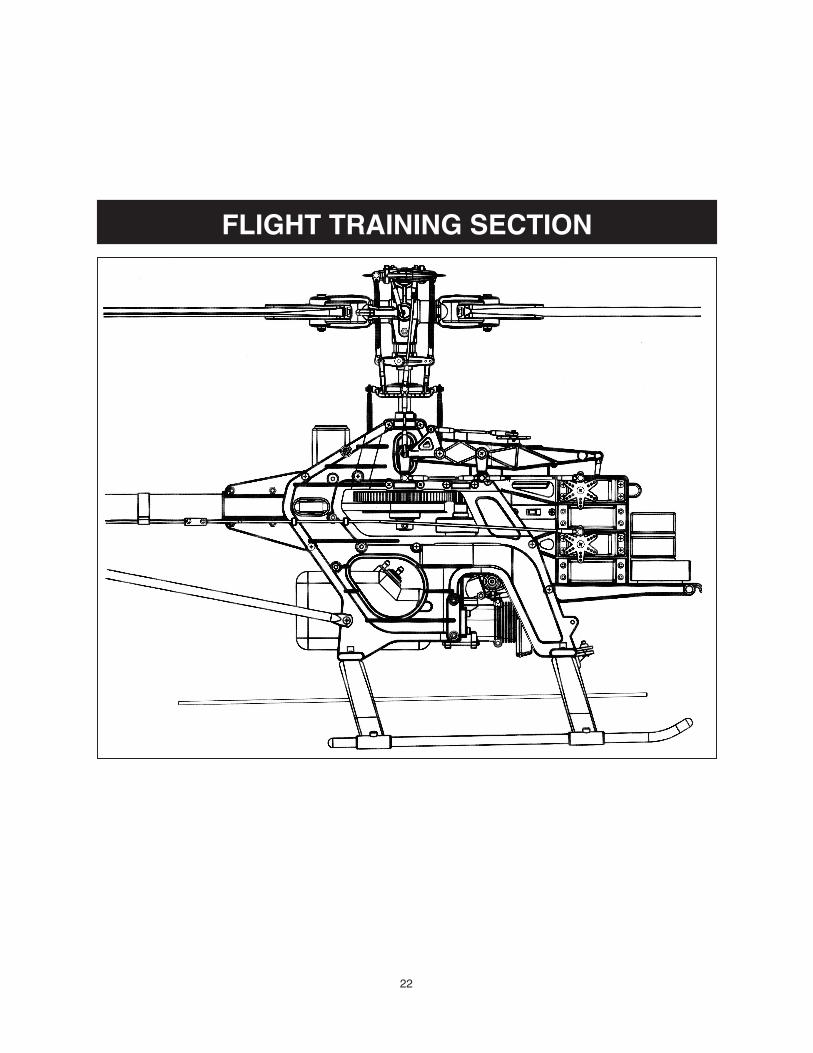
22
FLIGHT TRAINING SECTION
23
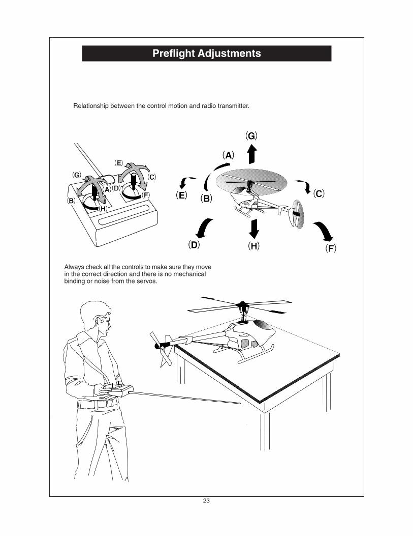
Preflight Adjustments
Relationship between the control motion and radio transmitter.
Always check all the controls to make sure they movein the correct direction and there is no mechanicalbinding or noise from the servos.
24
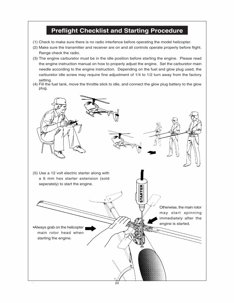
Preflight Checklist and Starting Procedure
(1) Check to make sure there is no radio interfence before operating the model helicopter.
(2) Make sure the transmitter and receiver are on and all controls operate properly before flight.
Range check the radio.
(3) The engine carburetor must be in the idle position before starting the engine. Please read
the engine instruction manual on how to properly adjust the engine. Set the carburetor main
needle according to the engine instruction. Depending on the fuel and glow plug used, the
carburetor idle screw may require fine adjustment of 1/4 to 1/2 turn away from the factory
setting.(4) Fill the fuel tank, move the throttle stick to idle, and connect the glow plug battery to the glow
plug.
(5) Use a 12 volt electric starter along with
a 6 mm hex starter extension (sold
seperately) to start the engine.
•Always grab on the helicopter
main rotor head when
starting the engine.
Otherwise, the main rotor
may start spinning
immediately after the
engine is started.
25
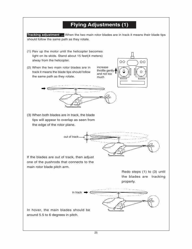
Flying Adjustments (1)
Tracking adjustment ... When the two main rotor blades are in track it means their blade tips
should follow the same path as they rotate.
(1) Rev up the motor until the helicopter becomes
light on its skids. Stand about 15 feet(4 meters)
alway from the helicopter.
(2) When the two main rotor blades are in
track it means the blade tips should follow
the same path as they rotate.
(3) When both blades are in track, the blade
tips will appear to overlap as seen from
the edge of the rotor plane.
If the blades are out of track, then adjust
one of the pushrods that connects to the
main rotor blade pitch arm.
Redo steps (1) to (3) until
the blades are tracking
properly.
In hover, the main blades should be
around 5.5 to 6 degrees in pitch.
out of track
in track
increasethrottle gentlyand not toomuch
26
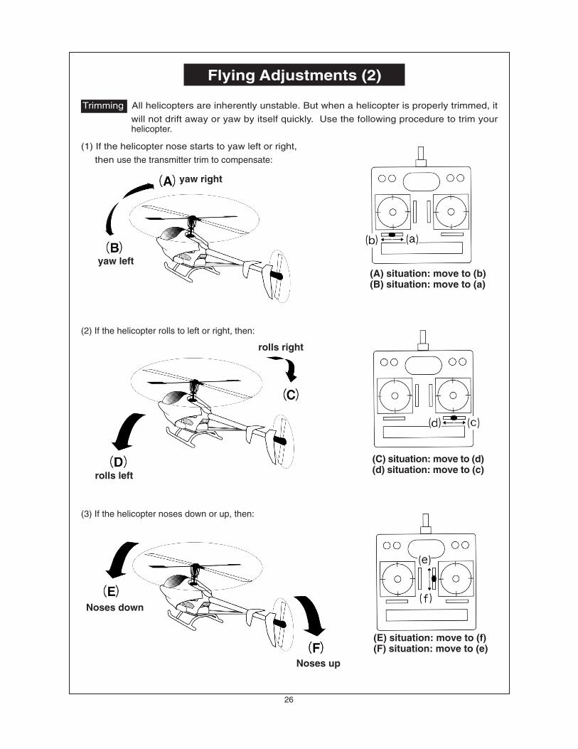
Flying Adjustments (2)
Trimming: All helicopters are inherently unstable. But when a helicopter is properly trimmed, it
will not drift away or yaw by itself quickly. Use the following procedure to trim yourhelicopter.
(1) If the helicopter nose starts to yaw left or right,
then use the transmitter trim to compensate:
(3) If the helicopter noses down or up, then:
yaw right
yaw left(A) situation: move to (b)(B) situation: move to (a)
(2) If the helicopter rolls to left or right, then:
rolls right
rolls left
(C) situation: move to (d)(d) situation: move to (c)
Noses down
Noses up
(E) situation: move to (f)(F) situation: move to (e)
27
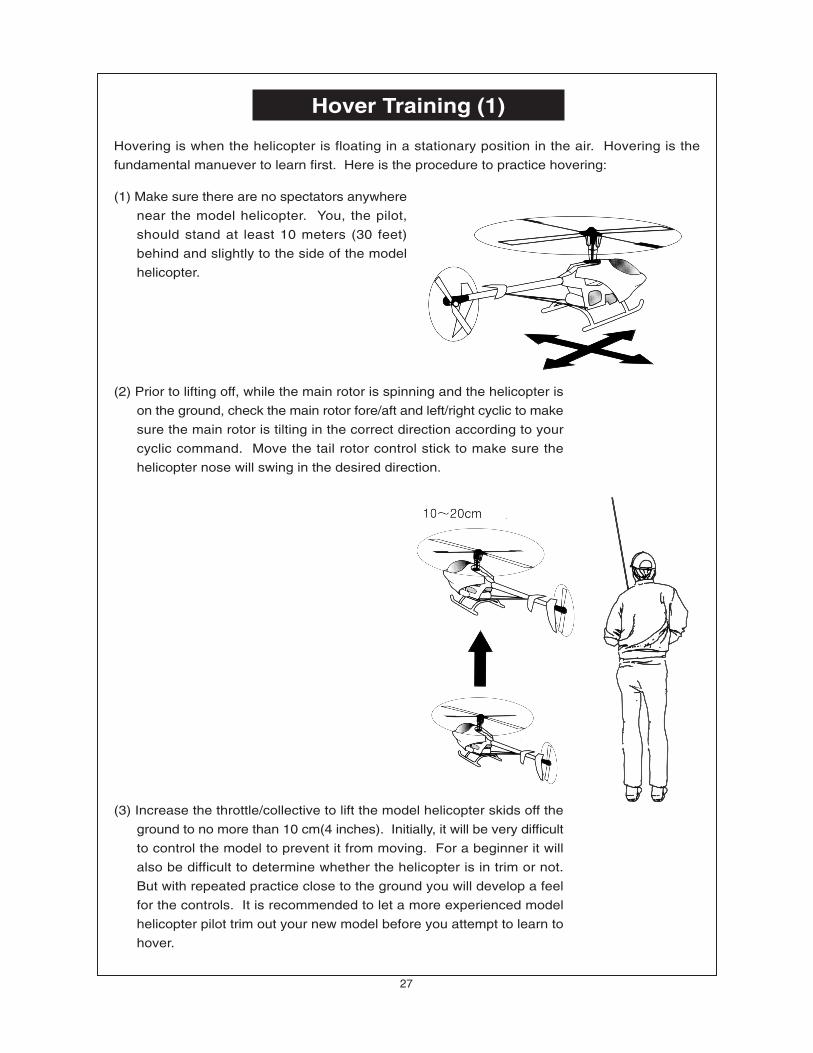
Hover Training (1)
Hovering is when the helicopter is floating in a stationary position in the air. Hovering is the
fundamental manuever to learn first. Here is the procedure to practice hovering:
(1) Make sure there are no spectators anywhere
near the model helicopter. You, the pilot,
should stand at least 10 meters (30 feet)
behind and slightly to the side of the model
helicopter.
(3) Increase the throttle/collective to lift the model helicopter skids off the
ground to no more than 10 cm(4 inches). Initially, it will be very difficult
to control the model to prevent it from moving. For a beginner it will
also be difficult to determine whether the helicopter is in trim or not.
But with repeated practice close to the ground you will develop a feel
for the controls. It is recommended to let a more experienced model
helicopter pilot trim out your new model before you attempt to learn to
hover.
(2) Prior to lifting off, while the main rotor is spinning and the helicopter is
on the ground, check the main rotor fore/aft and left/right cyclic to make
sure the main rotor is tilting in the correct direction according to your
cyclic command. Move the tail rotor control stick to make sure the
helicopter nose will swing in the desired direction.
28
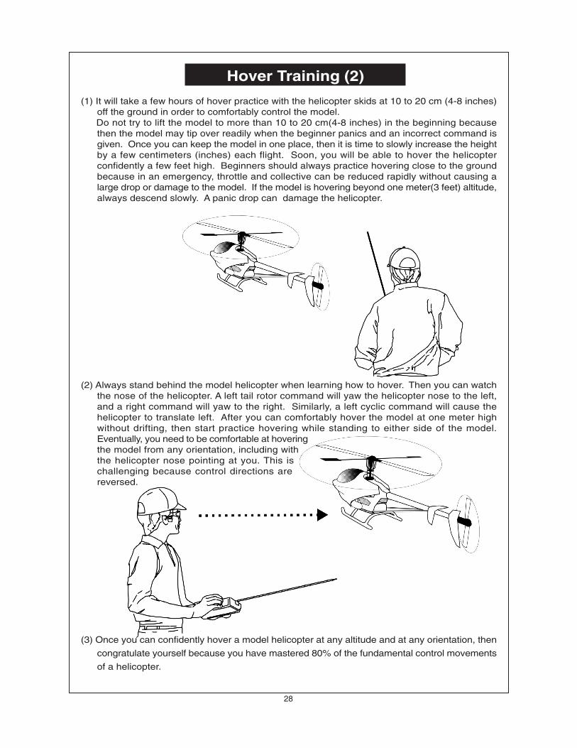
Hover Training (2)
(1) It will take a few hours of hover practice with the helicopter skids at 10 to 20 cm (4-8 inches)off the ground in order to comfortably control the model.
Do not try to lift the model to more than 10 to 20 cm(4-8 inches) in the beginning becausethen the model may tip over readily when the beginner panics and an incorrect command isgiven. Once you can keep the model in one place, then it is time to slowly increase the heightby a few centimeters (inches) each flight. Soon, you will be able to hover the helicopterconfidently a few feet high. Beginners should always practice hovering close to the groundbecause in an emergency, throttle and collective can be reduced rapidly without causing alarge drop or damage to the model. If the model is hovering beyond one meter(3 feet) altitude,always descend slowly. A panic drop can damage the helicopter.
(2) Always stand behind the model helicopter when learning how to hover. Then you can watchthe nose of the helicopter. A left tail rotor command will yaw the helicopter nose to the left,and a right command will yaw to the right. Similarly, a left cyclic command will cause thehelicopter to translate left. After you can comfortably hover the model at one meter highwithout drifting, then start practice hovering while standing to either side of the model.Eventually, you need to be comfortable at hoveringthe model from any orientation, including withthe helicopter nose pointing at you. This ischallenging because control directions arereversed.
(3) Once you can confidently hover a model helicopter at any altitude and at any orientation, then
congratulate yourself because you have mastered 80% of the fundamental control movements
of a helicopter.
29
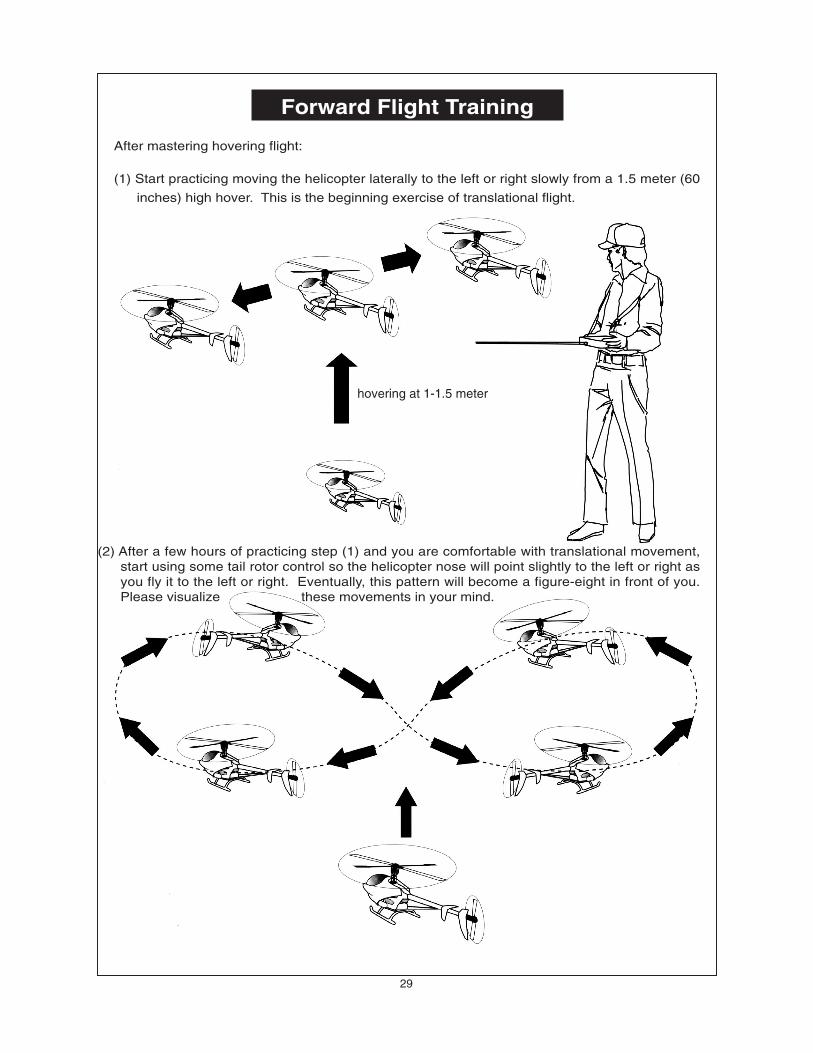
Forward Flight Training
After mastering hovering flight:
(1) Start practicing moving the helicopter laterally to the left or right slowly from a 1.5 meter (60
inches) high hover. This is the beginning exercise of translational flight.
(2) After a few hours of practicing step (1) and you are comfortable with translational movement,start using some tail rotor control so the helicopter nose will point slightly to the left or right asyou fly it to the left or right. Eventually, this pattern will become a figure-eight in front of you.Please visualize these movements in your mind.
hovering at 1-1.5 meter
30
MAINTENANCE SECTION
[1]The engine will not start.* The engine starting shaft will not turn:The engine may be flooded with too much fuel. Please remove the glow plug first, then turn the enginewith the electric starter until the excess fuel spits out of the glow plug hole.
* The engine turns when the electric starter is applied, but the engine will not start:(1) Is the glow plug working? Remove the glow plug and does the platinum coil glow red when a 1.5
volt battery is applied to the plug? If not, then the glow plug battery may be weak and old.(2) Is the carburetor needle properly set? Please refer to the engine instruction manual for the proper
needle setting.(3) Does the throttle control arm move properly and in the correct direction according your transmitter
command?
* Engine will start, but quits immediately.(1) Use the transmitter to increase the carburetor opening slightly. The throttle stick should never exceed
the 1/3 positiom when starting the engine.(2) Try a new or different type of glow plug. There are different types of glow plugs on the market for
different types of fuel and operating conditions. Seek the advice of experienced fliers and alsoexperiment with different types of glow plugs until you find the one that suits your operating conditionthe best.
*Engine runs, but the helicopter will not lift off.(1) Check the main rotor blade pitch angle, they should be set at 5.5 to 6 degrees when the transmitter
throttle/collective stick is at the center position.(2) Does the engine throttle arm move properly? The carburetor opening should be fully open when
the transmitter throttle/collective stick is moved up. The carburetor opening should be nearly closedwhen the transmitter throttle/collective stick is moved down. And the opening should be completelyclosed when the transmitter throttle/collective stick is moved down and the throttle trim is alsomoved down.
(3) The carburetor needle is not set properly. Close the needle (turn it clockwise) all the way, then openthe needle (turn it counter clockwise) 1 and 1/2 turns and try again. If the model still will not lift,then the engine maybe running too rich. If the symptom is the engine exhaust has a lot of smokeand the engine coughs and wants to quit when the transmitter throttle/collective stick is moved up, then close the needle 1/8 turn at a time, until the model will lift off. Do not turn the needle too farinward, that will make the engine run too lean and over-heat and damage the engine.
[2] Helicopter problems.* The helicopter shakes.(1) Is the blade spindle bent?(2) Is the flybar bent?(3) Is the main rotor shaft bent?(4) Are the two control paddles mounted at the same distance from the rotor shaft, and the paddles
are parallel to each other, and in the proper direction?(5) Is the tail rotor shaft bent? The tail rotor blades mounted properly or damaged?(6) Are the main rotor blades damaged or mounted in the proper orientation? The blades may require
additional balancing. The blade balance can be checked by removing both blades and then useone of the 4mm blade bolt and nut to hold the two blades together like a teeter totter. Then, holdthe blade bolt with your thumb and index finger. The two blades should teeter and remain in a levelposition. If not, then add some tape to the lighter blade near the blade tip until the two blades teeterin a level position. Hobby shops also sell blade balancers that are designed solely for balancingmodel helicopter blades.
31
After Flight Checklist
(1) Check every screw and bolt to make sure none has loosened due to vibration.(2) Check every rotating and movable part to ensure they still move smoothly and
normally.(3) Clean off the exhaust residue from the muffler, engine, and helicopter.(4) Check all movable parts, such as gears, ball links, belt, etc. for unusual wear.
Trouble Shooting
32
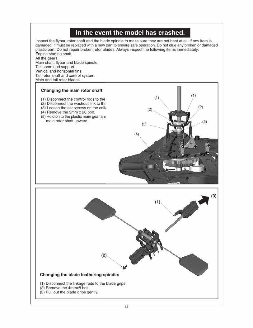
In the event the model has crashed.
Changing the main rotor shaft:
(1) Disconnect the control rods to the washout arms.(2) Disconnect the washout link to the swashplate.(3) Loosen the set screws on the collar.(4) Remove the 3mm x 20 bolt.(5) Hold on to the plastic main gear and pull the 10mm
main rotor shaft upward.
(1)
(2)
(3)
(1)
(2)
(3)
(4)
Inspect the flybar, rotor shaft and the blade spindle to make sure they are not bent at all. If any item isdamaged, it must be replaced with a new part to ensure safe operation. Do not glue any broken or damagedplastic part. Do not repair broken rotor blades. Always inspect the following items immediately:Engine starting shaft.All the gears.Main shaft, flybar and blade spindle.Tail boom and support.Vertical and horizontal fins.Tail rotor shaft and control system.Main and tail rotor blades.
Changing the blade feathering spindle:
(1) Disconnect the linkage rods to the blade grips.(2) Remove the 4mmx8 bolt.(3) Pull out the blade grips gently.
(3)(1)
(2)
(1)
(2)
(3)
(1)
(2)
(3)
(4)
33
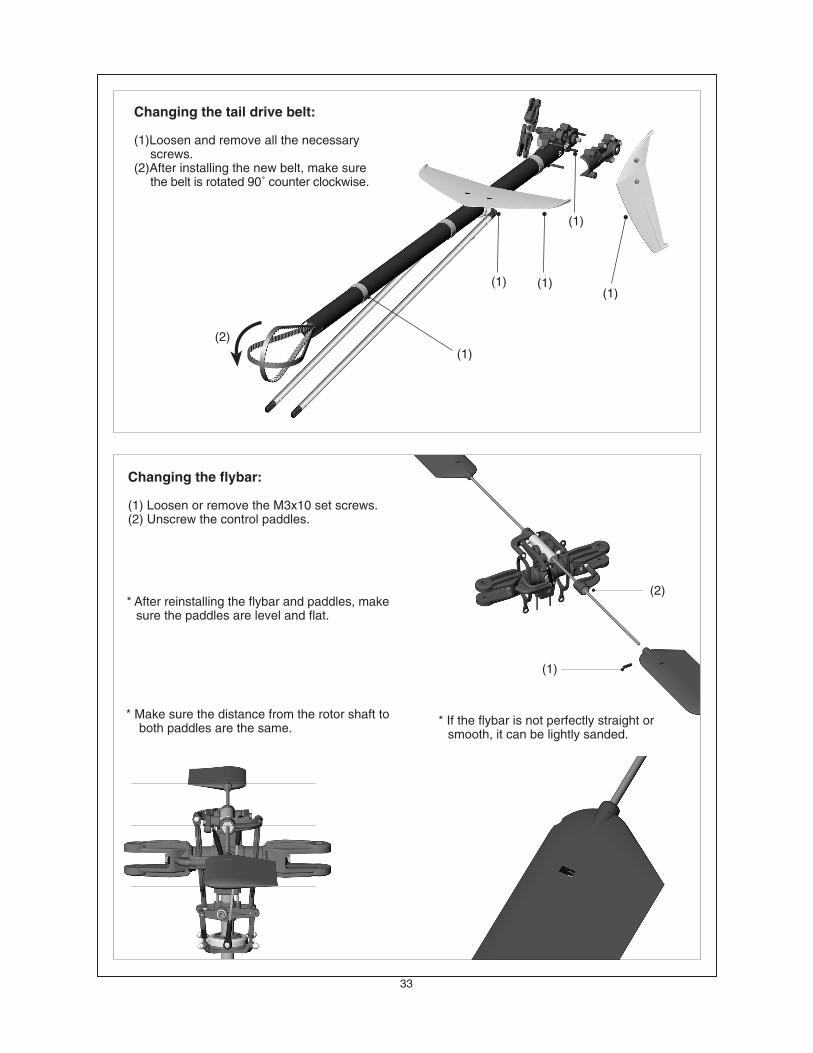
Changing the tail drive belt:
(1)Loosen and remove all the necessaryscrews.
(2)After installing the new belt, make surethe belt is rotated 90˚ counter clockwise.
(1)
(1) (1)
(1)
(1)
(2)
Changing the flybar:
(1) Loosen or remove the M3x10 set screws.(2) Unscrew the control paddles.
* Make sure the distance from the rotor shaft toboth paddles are the same.
* If the flybar is not perfectly straight orsmooth, it can be lightly sanded.
(2)
(1)
* After reinstalling the flybar and paddles, makesure the paddles are level and flat.
(3)
(4)
(1)
(5)
34
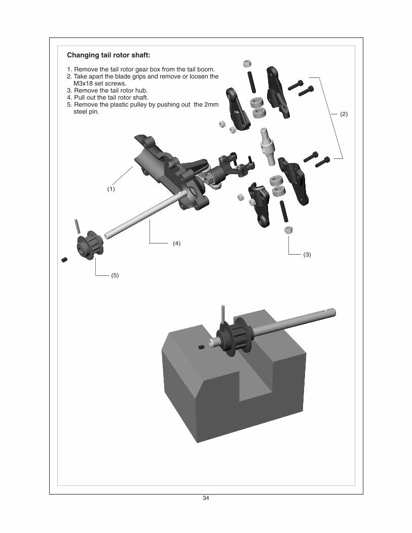
Changing tail rotor shaft:
1. Remove the tail rotor gear box from the tail boom.2. Take apart the blade grips and remove or loosen the
M3x18 set screws.3. Remove the tail rotor hub.4. Pull out the tail rotor shaft.5. Remove the plastic pulley by pushing out the 2mm
steel pin. (2)
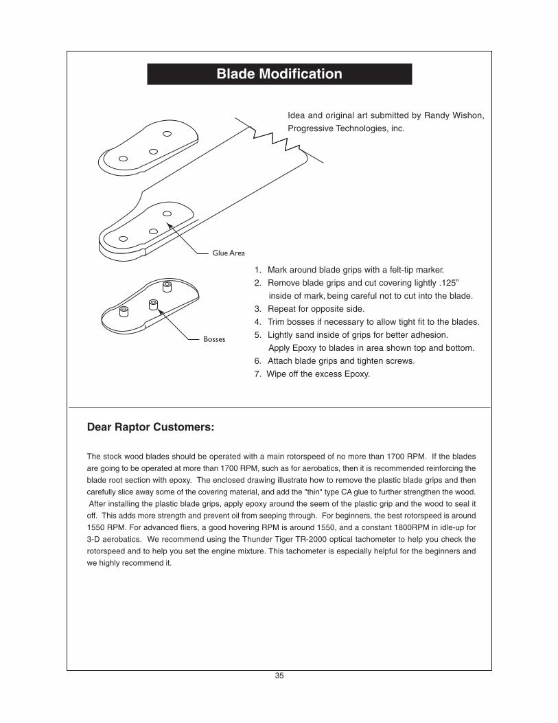
Blade Modification
1. Mark around blade grips with a felt-tip marker.
2. Remove blade grips and cut covering lightly .125”
inside of mark, being careful not to cut into the blade.
3. Repeat for opposite side.
4. Trim bosses if necessary to allow tight fit to the blades.
5. Lightly sand inside of grips for better adhesion.
Apply Epoxy to blades in area shown top and bottom.
6. Attach blade grips and tighten screws.
7. Wipe off the excess Epoxy.
Idea and original art submitted by Randy Wishon,
Progressive Technologies, inc.
Dear Raptor Customers:
The stock wood blades should be operated with a main rotorspeed of no more than 1700 RPM. If the blades
are going to be operated at more than 1700 RPM, such as for aerobatics, then it is recommended reinforcing the
blade root section with epoxy. The enclosed drawing illustrate how to remove the plastic blade grips and then
carefully slice away some of the covering material, and add the "thin" type CA glue to further strengthen the wood.
After installing the plastic blade grips, apply epoxy around the seem of the plastic grip and the wood to seal it
off. This adds more strength and prevent oil from seeping through. For beginners, the best rotorspeed is around
1550 RPM. For advanced fliers, a good hovering RPM is around 1550, and a constant 1800RPM in idle-up for
3-D aerobatics. We recommend using the Thunder Tiger TR-2000 optical tachometer to help you check the
rotorspeed and to help you set the engine mixture. This tachometer is especially helpful for the beginners and