NO. 0023E SPECIFICATIONS AND PARTS ARE SUBJECT TO CHANGE FOR IMPROVEMENT ROOM AIR CONDITIONER INDOOR UNIT + OUTDOOR UNIT SERVICE MANUAL AW REFER TO THE FOUNDATION MANUAL TECHNICAL INFORMATION FOR SERVICE PERSONNEL ONLY (W) (A) (kW) (B.T.U./h) (W) (A) (kW) (B.T.U./h) W H D (k g) TYPE MODEL POWER SOURCE TOTAL INPUT TOTAL AMPERES CAPACITY TOTAL INPUT TOTAL AMPERES CAPACITY DIMENSIONS (mm) NET WEIGHT SPECIFICATIONS RAS-25FH5 RAS-35FH5 CONTENTS SPECIFICATIONS ------------------------------------------------------------------- 4 HOW TO USE ----------------------------------------------------------------------- 5 CONSTRUCTION AND DIMENSIONAL DIAGRAM --------------------- 15 MAIN PARTS COMPONENT --------------------------------------------------- 17 WIRING DIAGRAM ---------------------------------------------------------------- 19 CIRCUIT DIAGRAM --------------------------------------------------------------- 20 BLOCK DIAGRAM ----------------------------------------------------------------- 22 BASIC MODE ----------------------------------------------------------------------- 23 REFRIGERATING CYCLE DIAGRAM --------------------------------------- 29 DESCRIPTION OF MAIN CIRCUIT OPERATION ----------------------- 30 SERVICE CALL Q & A ---------------------------------------------------------- 58 TROUBLE SHOOTING ----------------------------------------------------------- 61 PROCEDURE FOR DISASSEMBLY AND REASSEMBLY ------------ 87 PARTS LIST AND DIAGRAM -------------------------------------------------- 89 RAS-25FH5/RAC-25YH5 RAS-35FH5/RAC-35YH5 RAC-25YH5 RAC-35YH5 COOLING HEATING After installation FEBRUARY 2007 Hitachi Household Appliances(Wuhu) Co.,Ltd. RAS-25FH5 RAC-25YH5 DC INVERTER (WALL TYPE) 780 280 220 9.5 INDOOR UNIT OUTDOOR UNIT INDOOR UNIT OUTDOOR UNIT 1 PHASE, 50 Hz, 220-230V 580 (155 ~ 1,080) 3.11-2.97 2.50 (0.90 ~ 3.10) 8,530 (3,070 ~ 10,575) 790 (115 ~ 1,120) 3.99-3.82 3.40 (0.90 ~ 4.40) 11,601 (3,070 ~ 15,695) 548 35 780 280 220 9.5 548 35 1 PHASE, 50 Hz, 220-230V 980 (155 ~ 1,300) 4.69-4.49 3.50 (0.90 ~ 4.00) 11,942 (3,070 ~ 13,650) 1010 (115 ~ 1,300) 4.84-4.63 4.20 (0.90 ~ 5.00) 14,331 (3,070 ~ 17,745) RAS-35FH5 RAC-35YH5 750 (+91) 750 (+91) 288 (+47) 288 (+47)
Transcript
NO. 0023E
SPECIFICATIONS AND PARTS ARE SUBJECT TO CHANGE FOR IMPROVEMENT
ROOM AIR CONDITIONERINDOOR UNIT + OUTDOOR UNIT
SERVICE MANUAL
AW
REFER TO THE FOUNDATION MANUALTECHNICAL INFORMATION
PROCEDURE FOR DISASSEMBLY AND REASSEMBLY ------------ 87
PARTS LIST AND DIAGRAM -------------------------------------------------- 89
RAS-25FH5/RAC-25YH5RAS-35FH5/RAC-35YH5
RAC-25YH5RAC-35YH5
COOLING
HEATING
After installation
FEBRUARY 2007 Hitachi Household Appliances(Wuhu) Co.,Ltd.
RAS-25FH5 RAC-25YH5
DC INVERTER (WALL TYPE)
780
280
220
9.5
INDOOR UNIT OUTDOOR UNITINDOOR UNITOUTDOOR UNIT
1 PHASE, 50 Hz, 220-230V
580 (155 ~ 1,080)
3.11-2.97
2.50 (0.90 ~ 3.10)
8,530 (3,070 ~ 10,575)
790 (115 ~ 1,120)
3.99-3.82
3.40 (0.90 ~ 4.40)
11,601 (3,070 ~ 15,695)
548
35
780
280
220
9.5
548
35
1 PHASE, 50 Hz, 220-230V
980 (155 ~ 1,300)
4.69-4.49
3.50 (0.90 ~ 4.00)
11,942 (3,070 ~ 13,650)
1010 (115 ~ 1,300)
4.84-4.63
4.20 (0.90 ~ 5.00)
14,331 (3,070 ~ 17,745)
RAS-35FH5 RAC-35YH5
750 (+91) 750 (+91)
288 (+47) 288 (+47)
SAFETY DURING REPAIR WORK
First, I must disconnect
the power cord plug
from the power outlet.
1. In order to disassemble and repair the unitin question, be sure to disconnect the powercord plug from the power outlet beforestarting the work.
2. If it is necessary to replace any parts, they should be replaced with respective genuine parts for the unit, andthe replacement must be effected in correct manner according to the instructions in the Service Manual of theunit.
If the contacts of electricalparts are defective, replace theelectrical parts without trying torepair them.
3. After completion of repairs, the initial state shouldbe restored.
4. Lead wires should be connected and laid as in theinitial state.
5. Modification of the unit by user himself shouldabsolutely be prohibited.
6. Tools and measuring instruments for use in repairs or inspection should be accurately calibrated in advance.
7. In installing the unit having been repaired, be careful to prevent the occurence of any accident such aselectrical shock, leak of current, or bodily injury due to the drop of any part.
8. To check the insulation of the unit, measure the insulation resistance between the power cord plug and groundingterminal of the unit. The insulation resistance should be 1M or more as measured by a 500V DC megger.
9. The initial location of installation such as window, floor or the other should be checked for being and safeenough to support the repaired unit again.If it is found not so strong and safe, the unit should be installed at the initial location reinforced or at a newlocation.
10. Any inflammable thing should never beplaced about the location of installation.
11. Check the grounding to see whether it isproper or not, and if it is found improper,connect the grounding terminal to the earth.
DANGER
– 1 –
WORKING STANDARDS FOR PREVENTING BREAKAGE OF SEMICONDUCTORS
1. ScopeThe standards provide for items to be generally observed in carrying and handling semiconductors in relativemanufacturers during maintenance and handling thereof. (They apply the same to handling of abnormalgoods such as rejected goods being returned).
2. Object parts
(1) Micro computer(2) Integrated circuits (IC)(3) Field-effect transistors (FET)(4) P.C. boards or the like on which the parts mentioned in (1) and (2) of this paragraph are equipped.
3. Items to be observed in handling
(1) Use a conductive container for carrying and storing of parts. (Even rejected goods should be handled inthe same way).
Fig. 1 Conductive Container
IC
A conductive polyvinyl bag IC
Conductive sponge
(2) When any part is handled uncovered (in counting, packing and the like), the handling person must alwaysuse himself as a body earth. (Make yourself a body earth by passing one M ohm earth resistance througha ring or bracelet).
(3) Be careful not to touch the parts with your clothing when you hold a part even if a body earth is beingtaken.
(4) Be sure to place a part on a metal plate with grounding.
(5) Be careful not to fail to turn off power when you repair the printed circuit board. At the same time, try torepair the printed circuit board on a grounded metal plate.
1M
Fig. 2 Body Earth
Body earth(Elimik conductive band)
Clip for connection with agrounding wire
– 2 –
(6)Use a three wire type soldering iron including a grounding wire.
Use a high insulation mode (100V, 10MΩ or higher) when ordinary iron is to be used.
(7) In checking circuits for maintenance, inspection or some others, be careful not to have the test probes ofthe measuring instrument shortcircuit a load circuit or the like.
Bare copper wire (for body earth)
Workingtable
Resistor of 1 M (1/2W)
Earth wire
Fig. 3 Grounding of the working table
Metal plate (of aluminium, stainless steel, etc.)
Staple
Screw stop at the screwedpart using a rag plate
Soldering iron
Groundingwire
Fig. 4 Grounding a soldering iron
– 3 –
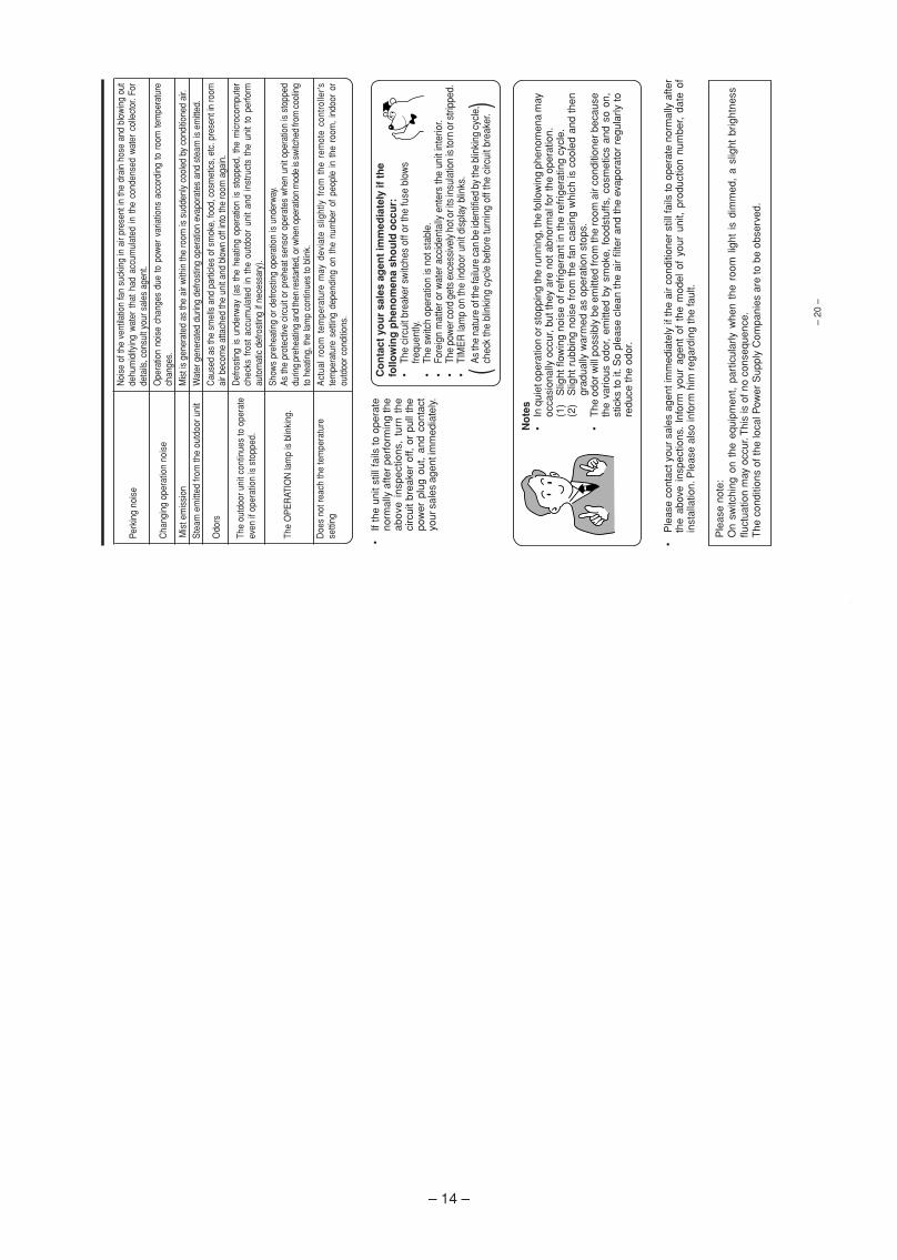
1. In quiet operation or stopping the running, slight flowing noise of refrigerant in the refrigerating cycle isheard occasionally, but this noise is not abnormal for the operation.
2. When it thunders near by, it is recommend to stop the operation and to disconnect the power cord plug fromthe power outlet for safety.
3. The room air conditioner does not start automatically after recovery of the electric power failure for prevent-ing fuse blowing. Re-press START/STOP button after 3 minutes from when unit stopped.
4. If the room air conditioner is stopped by adjusting thermostat, or missoperation, and re-start in a moment,there is occasion that the cooling and heating operation does not start for 3 minutes, it is not abnormal andthis is the result of the operation of IC delay circuit. This IC delay circuit ensures that there is no danger ofblowing fuse or damaging parts even if operation is restarted accidentally.
5. This room air conditioner should not be used at the cooling operation when the outside temperature isbelow -10°C (14°F).
6. This room air conditioner (the reverse cycle) should not be used when the outside temperature is below–15°C (5°F).If the reverse cycle is used under this condition, the outside heat exchanger is frosted and efficiency falls.
7. When the outside heat exchanger is frosted, the frost is melted by operating the hot gas system, it is nottrouble that at this time fan stops and the vapour may rise from the outside heat exchanger.
! CAUTION
– 4 –
SPECIFICATIONS
MODEL
FAN MOTOR
FAN MOTOR CAPACITOR
FAN MOTOR PROTECTOR
COMPRESSOR
COMPRESSOR MOTOR CAPACITOR
OVERLOAD PROTECTOR
OVERHEAT PROTECTOR
FUSE (for MICROPROCESSOR)
POWER RELAY
POWER SWITCH
TEMPORARY SWITCH
SERVICE SWITCH
TRANSFORMER
VARISTOR
NOISE SUPPRESSOR
THERMOSTAT
REMOTE CONTROL SWITCH (LIQUID CRYSTAL)
40 W
NO
NO
NO
EU1011DF
YES
YES
3.0A
G4A
NO
NO
YES
NO
450NR
YES
YES(IC)
NO
WITHOUT REFRIGERANT BECAUSECOUPLING IS FLARE TYPE.
UNIT
PIPES (MAX. 20m)
REFRIGERANT CHARGINGVOLUME(Refrigerant 410A)
870g
PWM DC35V
NO
NO
—
NO
NO
NO
NO
NO
YES
NO
NO
NO
NO
YES(IC)
YES
----------
YES
RAC-25YH5RAC-35YH5
RAS-25FH5RAS-35FH5
– 5 –
06K134_RAS_35YH6_001-014_E 10/25/06, 1:39 PM5
– 2
–
SA
FE
TY
PR
EC
AU
TIO
N•
Ple
ase
read
the
“Saf
ety
Pre
caut
ion”
car
eful
ly b
efor
e op
erat
ing
the
unit
to e
nsur
e co
rrec
t usa
ge o
f the
uni
t.•
Pay
spe
cial
atte
ntio
n to
sig
ns o
f “
War
nin
g”
and
“ C
auti
on
”. T
he “
War
ning
” se
ctio
n co
ntai
nsm
atte
rs w
hich
, if
not
obse
rved
str
ictly
, m
ay c
ause
dea
th o
r se
rious
inj
ury.
The
“C
autio
n” s
ectio
nco
ntai
ns m
atte
rs w
hich
may
resu
lt in
ser
ious
con
sequ
ence
s if
not o
bser
ved
prop
erly
. Ple
ase
obse
rve
all i
nstr
uctio
ns s
tric
tly to
ens
ure
safe
ty.
•T
he s
igns
indi
cate
the
follo
win
g m
eani
ngs.
(T
he fo
llow
ing
are
exam
ples
of s
igns
.)
•P
leas
e ke
ep th
is m
anua
l afte
r re
adin
g.
This
sig
n in
the
figur
e in
dica
tes
proh
ibiti
on.
Indi
cate
s th
e in
stru
ctio
ns th
at m
ust b
e fo
llow
ed.
WA
RN
ING
CA
UTI
ON
•D
o no
t rec
onst
ruct
the
unit.
Wat
er le
akag
e, fa
ult,
shor
t circ
uit o
r fir
e m
ay o
ccur
if y
ou r
econ
stru
ct th
e un
it by
your
self.
•P
leas
e as
k yo
ur s
ales
age
nt o
r qu
alifi
ed t
echn
icia
n fo
r th
e in
stal
latio
n of
you
run
it.W
ater
leak
age,
sho
rt c
ircui
t or
fire
may
occ
ur if
you
inst
all t
he u
nit b
y yo
urse
lf.•
Ple
ase
use
eart
h lin
e.D
o no
t pl
ace
the
eart
h lin
e ne
ar w
ater
or
gas
pipe
s, li
ghtn
ing-
cond
ucto
r, or
the
eart
h lin
e of
tel
epho
ne.
Impr
oper
ins
talla
tion
of e
arth
lin
e m
ay c
ause
ele
ctric
shoc
k.•
Be
sure
to u
se th
e sp
ecifi
ed p
ipin
g se
t for
R41
0A. O
ther
wis
e, th
is m
ay r
esul
t in
brok
en c
oppe
r pi
pes
or fa
ults
.•
A c
ircui
t bre
aker
sho
uld
be in
stal
led
depe
ndin
g on
the
mou
ntin
g si
te o
f the
uni
t.W
ithou
t a c
ircui
t bre
aker
, the
dan
ger
of e
lect
ric s
hock
exi
sts.
•D
o no
t ins
tall
the
unit
near
a lo
catio
n w
here
ther
e is
flam
mab
le g
as.
The
out
door
uni
t may
cat
ch fi
re if
flam
mab
le g
as le
aks
arou
nd it
. Pip
ing
shal
l be
suita
ble
supp
orte
d w
ith a
max
imum
spa
cing
of 1
m b
etw
een
the
supp
orts
.•
Ple
ase
ensu
re s
moo
th fl
ow o
f wat
er w
hen
inst
allin
g th
e dr
ain
hose
. If a
ny fa
ilure
is fo
und
in th
e dr
ain
path
, wat
er d
rops
from
the
indo
or a
nd o
utdo
or u
nits
, cau
sing
wet
hou
seho
ld e
ffect
s.•
Mak
e su
re th
at a
sin
gle
phas
e 23
0V p
ower
sou
rce
is u
sed.
The
use
of
othe
r po
wer
sou
rces
may
cau
se e
lect
rical
com
pone
nts
to o
verh
eat
and
lead
to fi
re.
PRO
HIBI
TIO
N
CONN
ECT
EART
H LI
NE
PRO
HIBI
TIO
N
PRO
HIBI
TIO
N
•S
houl
d ab
norm
al s
ituat
ion
aris
e (li
ke b
urni
ng s
mel
l), p
leas
e st
op o
pera
ting
the
unit
and
rem
ove
plug
from
the
sock
et o
r tu
rn o
ff th
e ci
rcui
t bre
aker
. Con
tact
you
rag
ent.
Faul
t, sh
ort
circ
uit
or f
ire m
ay o
ccur
if
you
cont
inue
to
oper
ate
the
unit
unde
r ab
norm
al s
ituat
ion.
•P
leas
e co
ntac
t you
r ag
ent f
or m
aint
enan
ce.
Impr
oper
sel
f mai
nten
ance
may
cau
se e
lect
ric s
hock
and
fire
.
•P
leas
e co
ntac
t you
r ag
ent i
f you
nee
d to
rem
ove
and
rein
stal
l the
uni
t.E
lect
ric s
hock
or
fire
may
occ
ur if
you
rem
ove
and
rein
stal
l the
uni
t you
rsel
f im
prop
erly
.
WA
RN
ING
PR
EC
AU
TIO
NS
DU
RIN
G IN
STA
LL
AT
ION
PR
EC
AU
TIO
NS
DU
RIN
G S
HIF
TIN
G O
R M
AIN
TE
NA
NC
E
“OFF
”
PRO
HIBI
TIO
N
•A
void
an
exte
nded
per
iod
of d
irect
air
flow
for
your
hea
lth.
•D
o no
t co
nnec
t th
e po
wer
cal
be w
ith a
n ex
tens
ion
cabl
e or
do
not
plug
too
man
yle
ads
of th
e ot
her
elec
tric
app
lianc
e in
to th
e so
cket
whe
re th
is c
able
is p
lugg
ed.
In a
dditi
on, w
ire th
e ca
ble
with
som
e al
low
ance
s to
pre
vent
the
cabl
e fro
m s
tretc
hing
.N
ot d
oing
so
will
cau
se a
n el
ectr
ical
sho
ck, h
eat g
ener
atio
n or
fire
.
PRO
HIBI
TIO
N
•D
o no
t pu
t ob
ject
s lik
e th
in r
ods
into
the
pan
el o
f bl
ower
and
suc
tion
side
beca
use
the
high
-spe
ed fa
n in
side
may
cau
se d
ange
r.
•D
o no
t bun
dle
the
pow
er c
able
, pul
l it,
put s
omet
hing
on
it, h
eat i
t, pr
oces
s it,
or
put i
t bet
wee
n th
ings
. Bre
akag
e of
the
pow
er c
able
may
res
ult.
Use
of a
dam
aged
cab
le m
ay c
ause
an
elec
tric
al s
hock
or
a fir
e.
PRO
HIBI
TIO
N
PRO
HIBI
TIO
N
HO
W T
O U
SE
– 3
–
WA
RN
ING
PR
EC
AU
TIO
NS
DU
RIN
G O
PE
RA
TIO
N
•D
o no
t use
any
con
duct
or a
s fu
se w
ire, t
his
coul
d ca
use
fata
l acc
iden
t.
PRO
HIBI
TIO
N
•D
urin
g th
unde
r st
orm
, dis
conn
ect t
he p
lug
top
or tu
rn o
ff th
e ci
rcui
t bre
aker
.
•S
pray
can
s an
d ot
her
com
bust
ible
s sh
ould
not
be
loca
ted
with
in a
met
er o
f the
air
outle
ts o
f bot
h in
door
and
out
door
uni
ts.
As
a sp
ray
can’
s in
tern
al p
ress
ure
can
be in
crea
sed
by h
ot a
ir, a
rupt
ure
may
resu
lt.
“OFF
”
CA
UTI
ON
PRO
HIBI
TIO
N
•T
he p
rodu
ct s
hall
be o
pera
ted
unde
r th
e m
anuf
actu
rer
spec
ifica
tion
and
not
for
any
othe
r in
tend
ed u
se.
PRO
HIBI
TIO
N
DON’
T W
ET
•D
o no
t atte
mpt
to o
pera
te th
e un
it w
ith w
et h
ands
, thi
s co
uld
caus
e fa
tal a
ccid
ent.
STRI
CTLY
OBS
ERVE
PREC
AUTI
ONS
PRO
HIBI
TIO
N
PRO
HIBI
TIO
N
PRO
HIBI
TIO
N
PRO
HIBI
TIO
N
PRO
HIBI
TIO
N
•W
hen
oper
atin
g th
e un
it w
ith b
urni
ng e
quip
men
ts,
regu
larly
ven
tilat
eth
e ro
om to
avo
id o
xyge
n in
suffi
cien
cy.
•D
o no
t dire
ct th
e co
ol a
ir co
min
g ou
t fro
m th
e ai
r-co
nditi
oner
pan
el to
face
hou
seho
ld h
eatin
g ap
para
tus
as t
his
may
affe
ct t
he w
orki
ng o
fap
para
tus
such
as
the
elec
tric
ket
tle, o
ven
etc.
•D
o no
t was
h th
e un
it w
ith w
ater
or p
lace
a w
ater
con
tain
er s
uch
as a
vase
on
the
indo
or u
nit.
Ele
ctric
al le
akag
e co
uld
be p
rese
nt a
nd c
ause
ele
ctric
sho
ck.
•P
leas
e en
sure
that
out
door
mou
ntin
g fr
ame
is a
lway
s st
able
, firm
and
with
out d
efec
t. If
not,
the
outd
oor u
nit m
ay c
olla
pse
and
caus
e da
nger
.
•D
o no
t pla
ce p
lant
s or
ani
mal
s di
rect
ly u
nder
the
air f
low
as
it is
bad
for t
he p
lant
s or
anim
als.
•D
o no
t clim
b on
the
outd
oor
unit
or p
ut o
bjec
ts o
n it.
PRO
HIBI
TIO
N
PRO
HIBI
TIO
N
PRO
HIBI
TIO
N
DON’
T TO
UCH
DON’
T TO
UCH
•W
hen
oper
atin
g th
e un
it w
ith th
e do
or a
nd w
indo
ws
open
ed, (
the
room
hum
idity
is a
lway
s ab
ove
80%
) an
d w
ith th
e ai
r de
flect
or fa
cing
dow
n or
mov
ing
auto
mat
i-ca
lly fo
r a
long
per
iod
of ti
me,
wat
er w
ill c
onde
nse
on th
e ai
r de
flect
or a
nd d
rips
dow
n oc
casi
onal
ly. T
his
will
wet
you
r fu
rnitu
re. T
here
fore
, do
not
ope
rate
und
ersu
ch c
ondi
tion
for
a lo
ng ti
me.
•If
the
amou
nt o
f hea
t in
the
room
is a
bove
the
cool
ing
or h
eatin
g ca
pabi
lity
of th
eun
it (f
or e
xam
ple:
mor
e pe
ople
ent
erin
g th
e ro
om, u
sing
hea
ting
equi
pmen
ts a
ndet
c.),
the
pres
et r
oom
tem
pera
ture
can
not b
e ac
hiev
ed.
•T
his
appl
ianc
e es
peci
ally
indo
or u
nit c
lean
ing
mus
t be
perf
orm
ed b
y au
thor
ized
pers
onne
l onl
y. C
onsu
lt yo
ur s
ales
age
nt.
Usi
ng a
com
mer
cial
ly a
vaila
ble
dete
rgen
t or s
imila
r can
dam
age
the
plas
tic p
arts
or c
log
the
drai
n pi
pe, c
ausi
ng w
ater
to d
rip w
ith p
oten
tial e
lect
ric s
hock
haz
ard.
•D
o no
t to
uch
the
air
outle
t, bo
ttom
sur
face
and
alu
min
um f
in o
f th
e ou
tdoo
run
it.Yo
u m
ay g
et h
urt.
•D
o no
t tou
ch th
e re
frig
eran
t pip
e an
d co
nnec
ting
valv
e.B
urns
may
res
ult.
•T
his
appl
ianc
e is
not
inte
nded
for u
se b
y yo
ung
child
ren
or in
firm
per
sons
unl
ess
they
hav
e be
enad
equa
tely
sup
ervi
sed
by a
resp
onsi
ble
pers
on to
ens
ure
that
they
can
use
this
app
lianc
e sa
fely
.•
Youn
g ch
ildre
n sh
ould
be
supe
rvis
ed to
ens
ure
that
they
do
not p
lay
with
the
appl
ianc
e.
– 6 –
– 4
–
NAM
ES A
ND F
UNCT
IONS
OF
EACH
PAR
T
INDO
OR U
NIT
Air
filt
erTo
pre
vent
dus
t fro
m c
omin
g in
to th
e in
door
uni
t.(R
efer
pag
e 16
)
Fro
nt
pan
el
Ind
oo
r u
nit
ind
icat
ors
Ligh
t ind
icat
or s
how
ing
the
oper
atin
g co
nditi
on.
(Ref
er p
age
5)H
ori
zon
tal d
efle
cto
r Ver
tica
l def
lect
or
(Air
Ou
tlet
)(R
efer
pag
e 15
)
Rem
ote
co
ntr
olle
rS
end
out o
pera
tion
sign
al to
the
indo
or u
nit.
So
asto
ope
rate
the
who
le u
nit.
(Ref
er p
age
6)
MOD
EL N
AME
AND
DIM
ENSI
ONS
OUTD
OOR
UNIT
Air
ou
tlet
Whe
n “h
eatin
g” o
pera
tion
isp
erf
orm
ed
, co
ol
air
blo
ws
an
d
wh
en
“c
oo
lin
g”
or
“deh
umid
ifyin
g” o
pera
tion
ispe
rfor
med
, war
m a
ir bl
ows.
Dra
in h
ose
Dra
ins
the
dehu
mid
ified
wat
er fr
om th
e in
door
uni
t to
the
outd
oor
durin
g “c
oolin
g” o
r “de
hum
idify
ing”
ope
ratio
n.
Pip
ing
an
d W
irin
g
Air
inle
ts (
Rea
r an
d le
ft s
ides
)
Ab
ou
t th
e o
utd
oo
r u
nit
:•
Whe
n “S
top”
is s
elec
ted
durin
g op
erat
ion
of th
e in
door
unit,
the
fan
of
the
outd
oor
unit
cont
inue
s tu
rnin
g fo
r10
to 6
0 se
cond
s to
coo
l the
ele
ctric
par
ts d
own.
•In
hea
ting
oper
atio
n, c
onde
nsat
e or
wat
er d
ue t
ode
fros
ting
will
flow
.D
o no
t cov
er th
e dr
ain
port
of t
he o
utdo
or u
nit b
ecau
sesu
ch w
ater
may
free
ze in
the
chill
y ar
ea.
•W
hen
the
outd
oor
unit
is h
ung
on t
he c
eilin
g, i
nsta
llth
e bu
sh a
nd d
rain
pip
e on
the
dra
in p
ort
and
drai
nw
ater
.
Dra
in p
ort
(Bo
tto
m)
Ear
th t
erm
inal
(Low
er s
ecti
on
of
the
sid
e)
MO
DE
LW
IDT
H (
mm
)H
EIG
HT
(m
m)
DE
PT
H (
mm
)
RA
S-2
5FH
5, R
AS
-35F
H5
780
280
220
RA
C-2
5YH
5, R
AC
-35Y
H5
750
548
288
– 5
–
ENGLISH
NAM
ES A
ND F
UNCT
IONS
OF
EACH
PAR
T
INDO
OR U
NIT
INDI
CATI
ONS
TIM
ER
LA
MP
(O
ran
ge)
Thi
s la
mp
light
s w
hen
the
timer
is w
orki
ng.
FIL
TE
R L
AM
P (
Gre
en)
Whe
n th
e de
vice
is o
pera
ted
for a
tota
l of a
bout
200
hour
s, th
e F
ILT
ER
lam
p lig
hts
indi
cate
s th
at it
is ti
me
to c
lea
n t
he
filt
er.
Th
e l
am
p g
oe
s o
ut
wh
en
th
e“
(AU
TO
SW
ING
)” b
utto
n is
pre
ssed
whi
le t
heop
erat
ion
is s
topp
ed.
OP
ER
AT
ION
LA
MP
(Ye
llow
)T
his
lam
p lig
hts
durin
g op
erat
ion.
The
OP
ER
AT
ION
LA
MP
fla
shes
in
the
follo
win
gca
ses
durin
g he
atin
g.(1
)D
uri
ng
pre
hea
tin
gF
or a
bout
2-3
min
utes
afte
r st
artin
g up
.(2
)D
uri
ng
def
rost
ing
Def
rost
ing
will
be
perf
orm
ed a
bout
onc
e an
hou
rw
hen
fros
t for
ms
on th
e he
at e
xcha
nger
of t
heou
tdoo
r un
it, fo
r 5-
10 m
inut
es e
ach
time.
TE
MP
OR
AR
Y S
WIT
CH
�U
se th
is s
witc
h to
sta
rt a
nd s
top
whe
n th
e re
mot
e co
ntro
ller d
oes
not w
ork.
�T
his
tem
pora
ry o
pera
tion
will
be
at th
e m
ost r
ecen
t set
ting
mad
e. (T
he u
nit
will
imm
edia
tely
go
into
aut
omat
ic o
pera
tion
once
pow
er is
sw
itche
d on
.)
CA
UTI
ON
Turn
off
the
circ
uit
brea
ker
or p
ull o
utth
e po
wer
plu
g if
the
unit
is n
ot b
eop
erat
ed fo
r a
long
per
iod.
✩If
the
pow
er s
tays
on
and
the
unit
is n
ot o
pera
ted,
pow
er is
slig
htly
con
sum
ed in
the
cont
rol c
ircui
t.T
he p
ower
is s
aved
by
turn
ing
off t
he p
ower
sw
itch
(or t
he c
ircui
t bre
aker
whe
n th
e po
wer
is s
uppl
ied
from
the
outd
oor
unit)
.
Att
ach
ing
th
e ai
r cl
ean
sin
g a
nd
deo
do
rizi
ng
filt
ers
(Acc
esso
ries
) to
th
e fi
lter
fra
me.
•A
ttach
the
air
clea
nsin
g an
d de
odor
izin
g fil
ters
to th
e fr
ame
byge
ntly
com
pres
s its
bot
h si
des
and
rele
ase
afte
r in
sert
ion
into
filte
r fr
ame.
•T
he c
oolin
g ca
paci
ty is
slig
htly
wea
kene
d an
d th
e co
olin
g sp
eed
beco
mes
slo
wer
whe
n th
e ai
r cl
eans
ing
and
deod
oriz
ing
filte
rsar
e us
ed.
•A
ir cl
eans
ing
and
deod
oriz
ing
filte
rs a
re w
asha
ble
and
reus
able
up
to 2
0 tim
es b
y us
ing
vacu
umcl
eane
r or w
ater
rins
e un
der r
unni
ng ta
p w
ater
. Whe
n yo
u w
ant t
o re
new
it, p
leas
e as
k yo
ur s
ales
agen
t.
Fra
me
PO
WE
R S
WIT
CH
– 7 –
06K134_RAS_35YH6_001-014_E 10/25/06, 1:39 PM7
– 6
––
7 –
�S
ign
al e
mit
tin
g w
ind
ow
/tra
nsm
issi
on
sig
nP
oint
this
win
dow
tow
ard
the
indo
or u
nit w
hen
cont
rolli
ng it
.T
he tr
ansm
issi
on s
ign
blin
ks w
hen
a si
gnal
is s
ent.
�D
isp
lay
Thi
s in
dica
tes
the
room
tem
pera
ture
sel
ecte
d, c
urre
nt ti
me,
tim
er s
tatu
s,fu
nctio
n an
d in
tens
ity o
f circ
ulat
ion
sele
cted
.
�S
TAR
T/S
TOP
bu
tto
nP
ress
this
but
ton
to s
tart
ope
ratio
n. P
ress
it a
gain
to s
top
oper
atio
n.�
AU
TO S
WIN
G b
utt
on
Con
trol
s th
e an
gle
of th
e ho
rizon
tal a
ir de
flect
or.
�FA
N S
PE
ED
sel
ecto
rT
his
dete
rmin
es th
e fa
n sp
eed.
Eve
ry ti
me
you
pres
s th
is b
utto
n, th
e in
tens
ity o
fci
rcul
atio
n w
ill c
hang
e fr
om
(A
UT
O)
to
(H
I) to
(
ME
D)
to
(LO
W).
(Thi
s bu
tton
allo
ws
sele
ctin
g th
e op
timal
or
pref
erre
d fa
n sp
eed
for
each
oper
atio
n m
ode.
)
�S
LE
EP
bu
tto
nU
se th
is b
utto
n to
set
the
slee
p tim
er.
�T
EM
PE
RA
TU
RE
bu
tto
ns
Use
thes
e bu
ttons
to r
aise
or
low
er th
e te
mpe
ratu
re s
ettin
g. (
Kee
p pr
esse
d, a
ndth
e va
lue
will
cha
nge
mor
e qu
ickl
y.)
�T
IME
bu
tto
nU
se th
is b
utto
n to
set
and
che
ck th
e tim
e an
d da
te.
�R
ES
ET
bu
tto
nP
ress
this
but
ton
afte
r th
e ba
tterie
s ar
e re
plac
ed o
r w
hen
som
e irr
egul
arop
erat
ion
is fo
und.
�F
UN
CT
ION
sel
ecto
rU
se th
is b
utto
n to
sel
ect t
he o
pera
ting
mod
e. E
very
tim
e yo
u pr
ess
it, th
e m
ode
will
cha
nge
from
(
AU
TO
) to
(
HE
AT
) to
(
DE
HU
MID
IFY
) to
(
CO
OL)
and
to
(FA
N)
cycl
ical
ly.
�FA
N S
PE
ED
sel
ecto
r�
AU
TO S
WIN
G b
utt
on
�T
IME
R c
on
tro
lU
se th
ese
butto
ns to
set
the
timer
.�
OF
F-T
IME
R b
utt
on
S
elec
t the
turn
OF
F ti
me.
�O
N-T
IME
R b
utt
on
S
elec
t the
turn
ON
tim
e.�
RE
SE
RV
E b
utt
on
T
ime
setti
ng r
eser
vatio
n.�
CA
NC
EL
bu
tto
n
Can
cel t
ime
rese
rvat
ion.
VARI
OUS
FUNC
TION
S
� A
uto
Res
tart
Co
ntr
ol
•If
ther
e is
a p
ower
failu
re, o
pera
tion
will
be
auto
mat
ical
ly re
star
ted
whe
n th
e po
wer
is re
sum
ed w
ithpr
evio
us o
pera
tion
mod
e an
d ai
rflo
w d
irect
ion.
(As
the
oper
atio
n is
not
sto
pped
by
rem
ote
cont
rolle
r.)•
If yo
u in
tend
not
to c
ontin
ue th
e op
erat
ion
whe
n th
e po
wer
is re
sum
ed, s
witc
h of
f the
pow
er s
uppl
y.W
hen
you
switc
h on
the
circ
uit b
reak
er, t
he o
pera
tion
will
be
auto
mat
ical
ly re
star
ted
with
pre
viou
sop
erat
ion
mod
e an
d ai
rflo
w d
irect
ion.
Not
e:1.
If yo
u do
not
req
uire
Aut
o R
esta
rt C
ontr
ol, p
leas
e co
nsul
t you
r sa
les
agen
t.2.
Aut
o R
esta
rt C
ontr
ol is
not
ava
ilabl
e w
hen
Tim
er o
r S
leep
Tim
er m
ode
is s
et.
AUTO
MAT
IC O
PERA
TION
The
dev
ice
will
aut
omat
ical
ly d
eter
min
e th
e m
ode
of o
pera
tion,
HE
AT
or
CO
OL
depe
ndin
g on
the
initi
al r
oom
tem
pera
ture
. T
he s
elec
ted
mod
e of
ope
ratio
n w
ill c
hang
e w
hen
the
room
tem
pera
ture
varie
s.
Pre
ss th
e F
UN
CT
ION
sel
ecto
r so
that
the
disp
lay
indi
cate
s th
e (
AU
TO
) m
ode
of o
pera
tion.
•W
hen
AU
TO
has
bee
n se
lect
ed, t
he d
evic
e w
ill a
utom
atic
ally
dete
rmin
e th
e m
ode
of o
pera
tion,
HE
AT
or C
OO
L de
pend
ing
on th
e cu
rren
t roo
m te
mpe
ratu
re.
•W
hen
AU
TO
is f
irst
sele
cted
, th
e de
vice
will
det
erm
ine
the
curr
ent
room
tem
pera
ture
and
sel
ect
the
prop
er o
pera
tion
mod
e ac
cord
ingl
y.•
Whe
n th
e ai
r con
ditio
ner h
as a
djus
ted
the
room
's te
mpe
ratu
reto
the
nea
r pr
eset
tem
pera
ture
, it
will
beg
in t
o m
onito
rop
erat
ion.
If
the
room
tem
pera
ture
sub
sequ
ently
cha
nges
,th
e ai
r co
nditi
oner
will
onc
e ag
ain
sele
ct t
he a
ppro
pria
teop
erat
ion
(hea
ting
or c
oolin
g) t
o ad
just
the
tem
pera
ture
to
the
pres
et t
empe
ratu
re.
The
mon
itorin
g op
erat
ion
rang
e is
+ 3°
C r
elat
ive
to th
e pr
eset
tem
pera
ture
.•
If t
he
mo
de
au
tom
ati
cally
se
lect
ed
by
the
un
it i
s n
ot
satis
fact
ory
, m
an
ua
lly c
ha
ng
e t
he
mo
de
se
ttin
g (
he
at,
dehu
mid
ify, c
ool o
r fa
n).
1
NAM
ES A
ND F
UNCT
IONS
OF
EACH
PAR
T
RE
MO
TE
CO
NT
RO
LL
ER
•T
his
cont
rols
the
oper
atio
n of
the
indo
or u
nit.
The
ran
ge o
f co
ntro
l is
abou
t 7
met
ers.
If
indo
or li
ghtin
g is
con
trol
led
elec
tron
ical
ly,
the
rang
e of
cont
rol m
ay b
e sh
orte
r, in
som
e ca
ses,
the
cont
rol s
igna
l may
not
be
rece
ived
.T
his
unit
can
be fi
xed
on a
wal
l usi
ng th
e fix
ture
pro
vide
d. B
efor
e fix
ing
it, m
ake
sure
the
indo
or u
nit
can
be c
ontr
olle
d fr
om th
e re
mot
e co
ntro
ller.
•H
andl
e th
e re
mot
e co
ntro
ller
with
car
e.D
ropp
ing
it or
get
ting
it w
et m
ay c
ompr
omis
e its
sig
nal t
rans
mis
sion
cap
abili
ty.
•A
fter n
ew b
atte
ries
are
inse
rted
into
the
rem
ote
cont
rolle
r, th
e un
it w
ill in
itial
ly re
quire
app
roxi
mat
ely
10 s
econ
ds to
res
pond
to c
omm
ands
and
ope
rate
.
Pre
cau
tio
ns
for
Use
•D
o no
t put
the
rem
ote
cont
rolle
r in
the
follo
win
g pl
aces
.•
In d
irect
sun
light
•In
the
vici
nity
of a
hea
ter.
•H
andl
e th
e re
mot
e co
ntro
ller
care
fully
. Do
not d
rop
it on
the
floor
, and
prot
ect i
t fro
m w
ater
.•
Onc
e th
e ou
tdoo
r uni
t sto
ps, i
t will
not
rest
art f
or a
bout
3 m
inut
es (u
nles
syo
u tu
rn th
e po
wer
sw
itch
off a
nd o
n or
unp
lug
the
pow
er c
ord
and
plug
it in
aga
in).
Thi
s is
to p
rote
ct th
e de
vice
and
doe
s no
t ind
icat
e a
failu
re.
•If
you
pres
s th
e F
UN
CT
ION
sel
ecto
r but
ton
durin
g op
erat
ion,
the
devi
cem
ay s
top
for
abou
t 3 m
inut
es fo
r pr
otec
tion.
AU
TO
HE
AT
DE
HU
MID
IFY
CO
OL
FAN
FAN
SP
EE
DLO
WM
ED
HI
SLE
EP
ING
STO
P (
CA
NC
EL)
STA
RT
(RE
SE
RV
E)
STA
RT
/STO
P
TIM
E
TIM
ER
SE
T
TIM
ER
SE
LEC
TOR
ON
TIM
ER
OF
F T
IME
R
AU
TO S
WIN
G
Pre
ss th
e (
STA
RT
/ST
OP
) bu
tton.
Ope
ratio
n st
arts
with
a b
eep.
Pre
ss th
e bu
tton
agai
n to
sto
p op
erat
ion.
Pre
ss th
e (F
AN
SP
EE
D)
butto
n, A
UT
O a
nd L
OW
is a
vaila
ble.
�A
s th
e se
tting
s ar
e st
ored
in m
emor
y in
the
rem
ote
cont
rolle
r, yo
uon
ly h
ave
to p
ress
the
(S
TAR
T/S
TO
P)
butto
n ne
xt ti
me.
You
can
rais
e or
low
er t
he t
empe
ratu
re s
ettin
g as
nec
essa
ry b
ym
axim
um o
f 3°C
.
Pre
ss t
he t
empe
ratu
re b
utto
n an
d th
e te
mpe
ratu
rese
tting
will
cha
nge
by 1
°C e
ach
time.
•T
he p
rese
t te
mpe
ratu
re a
nd t
he a
ctua
l roo
m t
empe
ratu
re m
ayva
ry s
omew
hat d
epen
ding
on
cond
ition
s.
STA
RT
STO
P
– 8 –
06K134_RAS_35YH6_001-014_E 10/25/06, 1:39 PM8
– 8
–
Pre
ss t
he
(S
TAR
T/S
TOP
) bu
tton.
Hea
ting
oper
atio
n st
arts
with
a b
eep.
Pre
ss th
e bu
tton
agai
n to
sto
p op
erat
ion.
STA
RT
STO
P
HEAT
ING
OPER
ATIO
N
•U
se th
e de
vice
for
heat
ing
whe
n th
e ou
tdoo
r te
mpe
ratu
re is
und
er 2
1°C
.W
hen
it is
too
war
m (
over
21°
C),
the
heat
ing
func
tion
may
not
wor
k in
ord
er to
pro
tect
the
devi
ce.
•In
ord
er t
o ke
ep r
elia
bilit
y of
the
dev
ice,
ple
ase
use
this
dev
ice
abov
e -1
5°C
of
the
outd
oor
tem
pera
ture
.
Pre
ss t
he F
UN
CT
ION
sel
ecto
r so
tha
t th
e di
spla
y in
dica
tes
(H
EAT
).1
Set
the
des
ired
FAN
SP
EE
D w
ith t
he
(FA
N S
PE
ED
) bu
tton
(the
dis
play
indi
cate
s th
e se
tting
).
(A
UTO
):
The
fan
spee
d ch
ange
s au
tom
atic
ally
acc
ordi
ngto
the
tem
pera
ture
of t
he a
ir w
hich
blo
ws
out.
(H
I):
Eco
no
mic
al
as
the
ro
om
will
be
com
e w
arm
quic
kly.
But
you
may
feel
a c
hill
at th
e be
ginn
ing.
(M
ED
):
Qui
et.
(LO
W)
:M
ore
quie
t.
2
Set
the
des
ired
room
tem
pera
ture
with
the
TE
MP
ER
ATU
RE
butto
ns (
the
disp
lay
indi
cate
s th
e se
tting
).
The
tem
pera
ture
set
ting
and
the
actu
al r
oom
tem
pera
ture
may
vary
som
ewha
t dep
endi
ng o
n co
nditi
ons.
3 �A
s th
e se
tting
s ar
e st
ored
in m
emor
y in
the
rem
ote
cont
rolle
r, yo
uon
ly h
ave
to p
ress
the
(S
TAR
T/S
TOP
) bu
tton
next
tim
e.
� D
efro
stin
g
Def
rost
ing
will
be
perfo
rmed
abo
ut o
nce
an h
our
whe
n fr
ost f
orm
s on
the
heat
exc
hang
e of
the
outd
oor
unit,
for
5~10
min
utes
eac
h tim
e.
Dur
ing
defr
ostin
g op
erat
ion,
the
oper
atio
n la
mp
blin
ks in
cyc
le o
f 3 s
econ
ds o
n an
d 0.
5 se
cond
off.
The
max
imum
tim
e fo
r de
fros
ting
is 2
0 m
inut
es.
(If t
he p
ipin
g le
ngth
use
d is
long
er th
an u
sual
, fro
st w
ill li
kely
to fo
rm.)
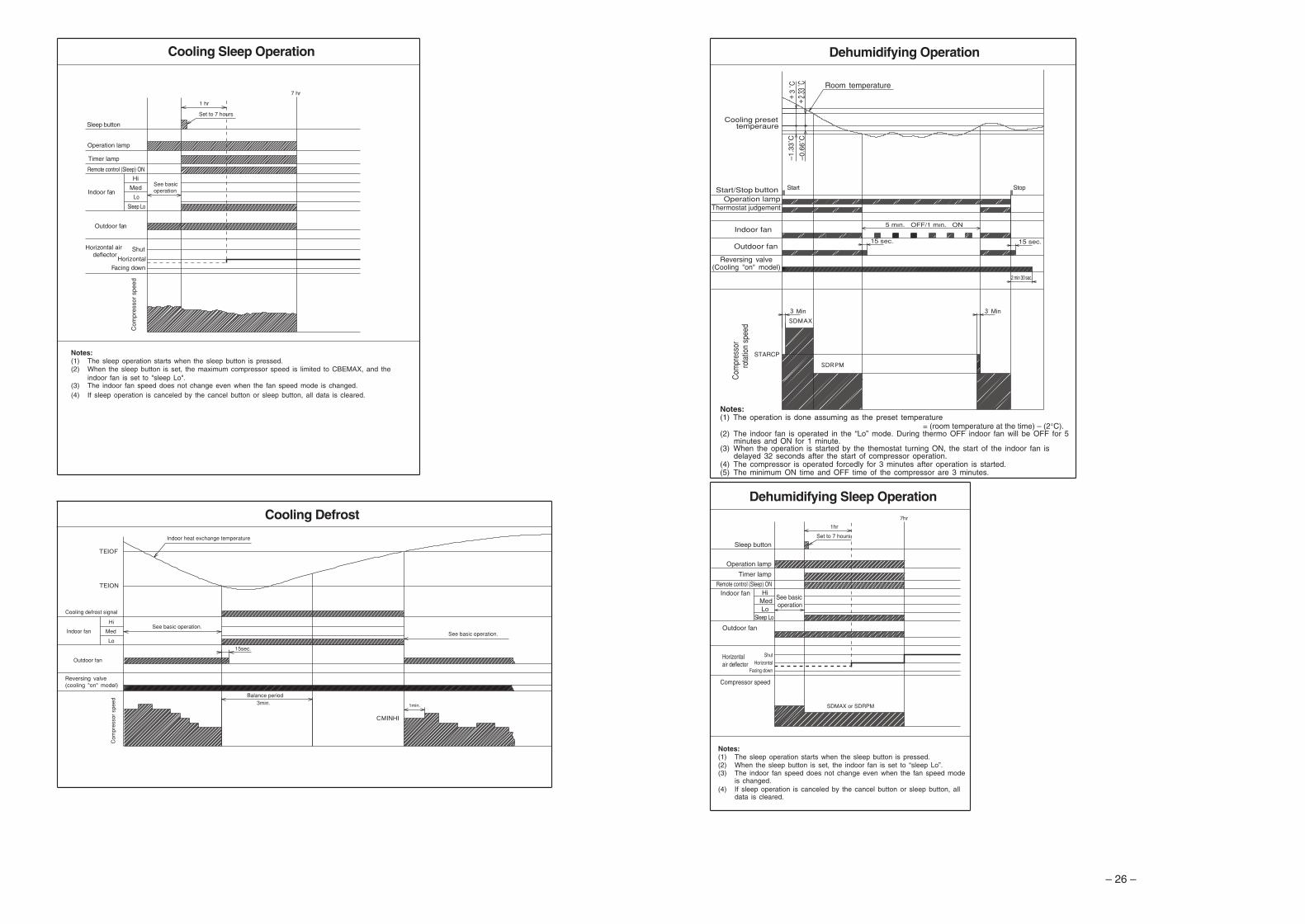
– 9
–
DEHU
MID
IFYI
NG O
PERA
TION
Use
the
devi
ce fo
r de
hum
idify
ing
whe
n th
e ro
om te
mpe
ratu
re is
ove
r 16
°C.
Whe
n it
is u
nder
15°
C, t
he d
ehum
idify
ing
func
tion
will
not
wor
k.
Pre
ss th
e (
STA
RT
/STO
P)
butto
n.S
TAR
TS
TOP
Pre
ss t
he F
UN
CT
ION
sel
ecto
r so
tha
t th
e di
spla
y in
dica
tes
(D
EH
UM
IDIF
Y).
The
FA
N S
PE
ED
is s
et a
t LO
W a
utom
atic
ally
.T
he F
AN
SP
EE
D b
utto
n do
es n
ot w
ork.
1 �W
hen
you
wan
t to
cha
nge
the
oper
atio
n m
ode,
ple
ase
use
the
FU
NC
TIO
N s
elec
tor.
�S
et th
e de
sire
d te
mpe
ratu
re is
ava
ilabl
e.�
You
also
can
use
the
FU
NC
TIO
N s
elec
tor
to s
elec
t thi
s op
erat
ion.
�D
ehu
mid
ifyi
ng
Fu
nct
ion
•D
ehum
idify
ing
take
s pl
ace
with
a t
arge
t te
mpe
ratu
re w
hich
is
slig
htly
low
er t
han
the
room
tem
pera
ture
set
ting.
(H
owev
er, t
arge
t tem
pera
ture
is 1
6°C
for
a te
mpe
ratu
re s
ettin
g of
16°
C.)
If t
he r
oom
tem
pera
ture
bec
omes
low
er t
han
the
targ
et v
alue
, op
erat
ion
stop
s. I
f th
e ro
omte
mpe
ratu
re b
ecom
es h
ighe
r th
an th
e ta
rget
val
ue, o
pera
tion
rest
arts
.•
The
pre
set r
oom
tem
pera
ture
may
not
be
reac
hed
depe
ndin
g on
the
num
ber
of p
eopl
e pr
esen
t in
the
room
con
ditio
ns.
– 9 –
06K134_RAS_35YH6_001-014_E 10/25/06, 1:39 PM9
– 10
–
Pre
ss t
he
(S
TAR
T/S
TOP
) bu
tton.
Coo
ling
oper
atio
n st
arts
with
a b
eep.
Pre
ss th
e bu
tton
agai
n to
sto
p op
erat
ion.
The
coo
ling
func
tion
does
not
sta
rt if
the
tem
pera
ture
set
ting
is h
ighe
r th
anth
e cu
rren
t roo
m te
mpe
ratu
re (e
ven
thou
gh th
e (O
PE
RAT
ION
)la
mp
light
s).
The
coo
ling
func
tion
will
sta
rt a
s so
on a
s yo
u se
t the
tem
pera
ture
belo
w th
e cu
rren
t roo
m te
mpe
ratu
re.
STA
RT
STO
P
COOL
ING
OPER
ATIO
N
Use
the
devi
ce fo
r co
olin
g w
hen
the
outd
oor
tem
pera
ture
is -
10 to
42°
C.
If hu
mid
ity is
ver
y hi
gh (
over
80%
) in
door
s, s
ome
dew
may
form
on
the
air
outle
t gril
le o
f the
indo
orun
it.
Pre
ss t
he F
UN
CT
ION
sel
ecto
r so
tha
t th
e di
spla
y in
dica
tes
(C
OO
L).
1S
et t
he d
esire
d FA
N S
PE
ED
with
the
(
FAN
SP
EE
D)
butto
n(t
he d
ispl
ay in
dica
tes
the
setti
ng).
(A
UTO
):
The
FA
N S
PE
ED
is H
I at f
irst a
nd v
arie
s to
ME
Dau
tom
atic
ally
whe
n th
e pr
eset
tem
pera
ture
has
been
rea
ched
.
(H
I):
Eco
nom
ical
as
the
room
will
bec
ome
cool
qui
ckly
.
(M
ED
):
Qui
et.
(LO
W)
:M
ore
quie
t.
2
Set
the
des
ired
room
tem
pera
ture
with
the
TE
MP
ER
ATU
RE
butto
ns (
the
disp
lay
indi
cate
s th
e se
tting
).
The
tem
pera
ture
set
ting
and
the
actu
al r
oom
tem
pera
ture
may
vary
som
ewha
t dep
endi
ng o
n co
nditi
ons.
3 �A
s th
e se
tting
s ar
e st
ored
in m
emor
y in
the
rem
ote
cont
rolle
r, yo
uon
ly h
ave
to p
ress
the
(S
TAR
T/S
TOP
) bu
tton
next
tim
e.
– 11
–
Pre
ss th
e (S
TAR
T/S
TOP
) but
ton.
Fan
ope
ratio
n st
arts
with
abe
ep.
Pre
ss th
e bu
tton
agai
n to
sto
p op
erat
ion.
STA
RT
STO
P
FAN
OPER
ATIO
N
You
can
use
the
devi
ce s
impl
y as
an
air c
ircul
ator
. Use
this
func
tion
to d
ry th
e in
terio
r of t
he in
door
uni
tat
the
end
of s
umm
er.
Pre
ss t
he F
UN
CT
ION
sel
ecto
r so
tha
t th
e di
spla
y in
dica
tes
(FA
N).
1P
ress
the
(FA
N S
PE
ED
) bu
tton.
(H
I):
The
str
onge
st a
ir bl
ow.
(M
ED
):
Qui
et.
(LO
W)
:M
ore
quie
t.
2
FAN
SP
EE
D (A
UTO
) …
Whe
n th
e A
UTO
fan
spee
d m
ode
is s
et in
the
cool
ing/
heat
ing
oper
atio
n:
For
the
heat
ing
oper
atio
n
•T
he f
an s
peed
will
aut
omat
ical
ly c
hang
e ac
cord
ing
to t
he t
empe
ratu
re o
fdi
scha
rged
air.
•A
s ro
om t
empe
ratu
re r
each
es t
he p
rese
t te
mpe
ratu
re,
a ve
ry l
ight
bre
eze
will
blo
w.
•O
pera
tion
star
ts in
the
“HI”
mod
e to
rea
ch th
e pr
eset
tem
pera
ture
.•
As
room
tem
pera
ture
app
roac
hes
the
pres
et t
empe
ratu
re,
fan
spee
d au
to-
mat
ical
ly s
witc
hes
to “
LOW
”.F
or th
e co
olin
g op
erat
ion
– 10 –
06K134_RAS_35YH6_001-014_E 10/25/06, 1:39 PM10
– 12
–
HOW
TO
SET
THE
TIM
ER
Tim
e, D
ay, M
on
thT
IME
, DAY
,M
ON
TH
(cu
rren
ttim
e, d
ay, m
onth
)
OF
F T
IME
R
ON
TIM
ER
RE
SE
RV
E
CA
NC
EL
OF
F-T
imer
ON
-Tim
er
ON
/OF
F-T
imer
1 S
et th
e cu
rren
t mon
th a
nd d
ayw
ith th
e T
IME
R c
ontr
ol b
utto
n.
DM
MD
Aft
er
you
ch
an
ge
th
eba
tterie
s;
Sta
rtS
top
You
can
set t
he d
evic
e to
turn
off
atth
e pr
esen
t tim
e.
1 P
ress
th
e
(O
FF
-TIM
ER
)bu
tton.
The
(
OF
F)
mar
k bl
inks
on th
e di
spla
y.
The
dev
ice
will
turn
on
at th
ede
sign
ated
tim
es.
1
Pre
ss
the
(ON
-TIM
ER
)bu
tton.
The
(ON
) mar
k bl
inks
on
the
disp
lay.
AM
Sta
rtS
top
•Th
e de
vice
will
tur
n on
(of
f) an
dof
f (on
) at t
he d
esig
nate
d tim
es.
•Th
e sw
itchi
ng o
ccur
s fir
st a
t th
epr
eset
tim
e th
at c
omes
ear
lier.
•Th
e ar
row
mar
k ap
pear
ing
on th
edi
spla
y in
dica
tes
the
sequ
ence
of
switc
hing
ope
ratio
ns.
1 P
ress
the
(OF
F-
TIM
ER
) bu
tton
so th
atth
e
(O
FF
) m
ark
blin
ks.
2 S
et t
he t
urn-
off
time
with
the
TIM
ER
con
trol
butto
n.P
ress
the
(RE
SE
RV
E)
butto
n.
PM
3
Pre
ss t
he
(ON
-T
IME
R) b
utto
n so
that
the
(OF
F) m
ark
light
s an
dth
e(O
N)
mar
k bl
inks
.
PM
AM
How
to
Can
cel R
eser
vati
on
Poi
nt th
e si
gnal
win
dow
of t
he r
emot
e co
ntro
ller
tow
ard
the
indo
or u
nit,
and
pres
s th
e (
CA
NC
EL)
butto
n.T
he
(RE
SE
RV
ED
) sig
n go
es o
ut w
ith a
bee
p an
d th
e (T
IME
R) l
amp
turn
s of
f on
the
indo
or u
nit.
NO
TE
You
can
set o
nly
one
of th
e O
FF
-tim
er,
ON
-tim
er a
nd O
N/O
FF
-tim
er.
Sta
rtS
top
AM
PM
– 13
–
2
Se
t th
e
(TIM
E)
butto
n.3
Set
the
curr
ent t
ime
with
the
TIM
ER
con
trol
but
ton.
4 P
ress
th
e
(T
IME
)b
utt
on
a
ga
in.
Th
e
tim
ein
dic
ati
on
sta
rts
lig
hti
ng
inst
ead
of fl
ashi
ng.
•T
he t
ime
indi
catio
n w
illdi
sapp
ear a
utom
atic
ally
in 1
0se
cond
s.
•To
che
ck t
he c
urre
nt t
ime
setti
ng, p
ress
the
(TI
ME
)bu
tton
twic
e.Th
e se
tting
of
the
curr
ent
time
is n
ow c
ompl
ete.
AM
PM
PM
PM
Exa
mpl
e: T
he c
urre
nt ti
me
is 1
:30p
.m.
2 S
et
the
tu
rn-o
ff t
ime
with
the
TIM
ER
con
trol
but
ton.
PM
3 P
oint
the
sign
al w
indo
w o
f the
rem
ote
cont
rolle
r to
war
d th
e in
door
uni
t,an
d pr
ess
the
(RE
SE
RV
E)
butto
n.Th
e (
OFF
) m
ark
star
ts li
ghtin
g in
stea
d of
flas
hing
and
the
(R
ES
ER
VE
D)
sign
ligh
ts. A
bee
p oc
curs
and
the
(TIM
ER
) lam
p lig
hts
on th
e in
door
uni
t.
PM
Exa
mpl
e: T
he d
evic
e w
ill tu
rn o
ff at
11:
00p.
m.
The
set
ting
of tu
rn-o
ff tim
e is
now
com
plet
e.
2 S
et
the
tu
rn-o
n t
ime
with
the
TIM
ER
con
trol
but
ton.
AM
3 P
oint
the
sign
al w
indo
w o
f the
rem
ote
cont
rolle
r to
war
d th
e in
door
uni
t,an
d pr
ess
the
(RE
SE
RV
E)
butto
n.T
he(O
N) m
ark
star
ts li
ghtin
g in
stea
d of
flas
hing
and
the
(RE
SE
RV
ED
)si
gn li
ghts
. A b
eep
occu
rs a
nd th
e (T
IME
R) l
amp
light
s on
the
indo
or u
nit.
AM
Exa
mpl
e:T
he d
evic
e w
ill tu
rn o
n ea
rly s
o th
at th
e pr
eset
tem
pera
ture
be
alm
ost r
each
ed a
t 7:0
0 a.
m.
The
set
ting
of th
e tu
rn-o
n tim
e is
now
com
plet
e.
4 S
et
the
tu
rn-o
n t
ime
with
the
TIM
ER
con
trol
but
ton.
5 P
oint
the
sign
al w
indo
w o
f the
rem
ote
cont
rolle
r to
war
d th
e in
door
uni
t,an
d pr
ess
the
(RE
SE
RV
E)
butto
n.T
he(O
N) m
ark
star
ts li
ghtin
g in
stea
d of
flas
hing
and
the
(RE
SE
RV
ED
)si
gn li
ghts
. A b
eep
occu
rs a
nd th
e (T
IME
R) l
amp
light
s on
the
indo
or u
nit.
Exa
mpl
e:Fo
r hea
ting,
the
devi
ce w
ill tu
rn o
ff at
10:
30 p
.m.,
an
d t
he
n t
urn
on
ea
rly
so t
ha
t th
e p
rese
tte
mpe
ratu
re b
e al
mos
t re
ache
d at
7:0
0 a.
m.;
for
cool
ing
and
dehu
mid
ifyin
g, i
t w
ill s
impl
ytu
rned
on
at 7
:00
a.m
. The
set
tings
of t
he tu
rnon
/off
times
are
now
com
plet
e.
PM
AM
PM
AM
•T
he t
imer
may
be
used
in
thre
e w
ays:
off-
timer
, on
-tim
er a
nd O
N/O
FF
(O
FF
/ON
)-tim
er.
Set
the
curr
ent t
ime
at fi
rst b
ecau
se it
ser
ves
as a
ref
eren
ce.
•A
s th
e tim
e se
tting
s ar
e st
ored
in
mem
ory
in t
he r
emot
e co
ntro
ller,
you
only
hav
e to
pre
ss t
he(R
ES
ER
VE
) bu
tton
is o
rder
to u
se th
e sa
me
setti
ngs
next
tim
e.
– 11 –
06K134_RAS_35YH6_001-014_E 10/25/06, 1:39 PM11
– 14
–
HOW
TO
SET
THE
SLEE
P TI
MER
Set
the
curr
ent t
ime
at fi
rst i
f it i
s no
t set
bef
ore
(see
the
page
s fo
r se
tting
the
curr
ent t
ime)
. Pre
ss th
e (
SLE
EP
) bu
tton
and
the
disp
lay
chan
ges
as s
how
n be
low
.
�S
LEE
P
Mod
eIn
dica
tion
Sle
ep T
imer
1
hour
2 ho
urs
3 ho
urs
7 ho
urs
Sle
ep ti
mer
off
Sle
ep T
imer
: T
he d
evic
e w
ill c
ontin
ue w
orki
ng fo
r th
e de
sire
d nu
mbe
r of
hour
s an
d th
en tu
rn o
ff.P
oint
the
sign
al w
indo
w o
f the
rem
ote
cont
rolle
r tow
ard
the
indo
or u
nit,
and
pres
s th
e S
LEE
P b
utto
n.T
he ti
mer
info
rmat
ion
will
be
disp
laye
d on
the
rem
ote
cont
rolle
r. T
he T
IME
Rla
mp
light
s w
ith a
bee
p fr
om t
he i
ndoo
r un
it. W
hen
the
slee
p tim
er h
asbe
en s
et, t
he d
ispl
ay in
dica
tes
the
turn
-off
time.
AM
Exa
mpl
e: If
you
set
3 h
ours
sle
ep ti
me
at11
:38
p.m
., th
e tu
rn-o
ff tim
e is
2:3
8 a.
m.
Sle
eptim
erS
tart
The
dev
ice
will
be
turn
ed o
ff by
the
slee
p tim
eran
d tu
rned
on
by o
n-tim
er.
1 S
et th
e O
N-t
imer
.
2 P
ress
the
(SLE
EP
) bu
tton
and
set t
he s
leep
tim
er.
AM
AM
For
hea
ting:
In t
his
case
, th
e de
vice
will
tur
n of
f in
2 ho
urs
(at 1
:38
a.m
.) a
nd tu
rn o
n ea
rlyso
tha
t th
e pr
eset
tem
pera
ture
will
be
alm
ost r
each
ed a
t 6:0
0 ne
xt m
orni
ng.
How
to
Can
cel R
eser
vati
on
Poi
nt th
e si
gnal
win
dow
of t
he r
emot
e co
ntro
ller
tow
ard
the
indo
or u
nit,
and
pres
s th
e (
CA
NC
EL)
butto
n.T
he
(RE
SE
RV
ED
) sig
n go
es o
ut w
ith a
bee
p an
d th
e (T
IME
R) l
amp
turn
s of
f on
the
indo
or u
nit.
N
OT
E
If yo
u se
t the
sle
ep ti
mer
whe
n th
e of
f-tim
e or
on/
off-
timer
has
bee
n se
t ear
lier,
the
slee
p tim
er b
ecom
esef
fect
ive
inst
ead
of th
e of
f - o
r on/
off-
timer
set
ear
lier.
– 15
–
ADJU
STIN
G TH
E AI
R DE
FLEC
TORS
1A
djus
tmen
t of
the
con
ditio
ned
air
in t
he u
pwar
d an
d do
wnw
ard
dire
ctio
ns.
The
hor
izon
tal a
ir de
flect
or is
aut
omat
ical
ly s
et to
the
prop
er a
ngle
suita
ble
for
each
ope
ratio
n. T
he d
efle
ctor
can
be
swun
g up
and
dow
n co
ntin
uous
ly a
nd a
lso
set
to t
he d
esire
d an
gle
usin
g th
e“
(A
UTO
SW
ING
)” b
utto
n.
•In
“C
oolin
g” o
pera
tion,
do
not
keep
the
hor
izon
tal
air
defle
ctor
sw
ingi
ng fo
r a lo
ng ti
me.
Som
e de
w m
ay fo
rm o
nth
e ho
rizon
tal a
ir de
flect
or a
nd d
ew m
ay d
rop.
CA
UTI
ON
2A
djus
tmen
t of t
he c
ondi
tione
d ai
r to
the
left
and
right
.
Hol
d th
e ve
rtic
al a
ir de
flect
or a
s sh
own
in th
e fig
ure
and
adju
stth
e co
nditi
oned
air
to th
e le
ft an
d rig
ht.
HOW
TO
EXCH
ANGE
THE
BAT
TERI
ES IN
THE
REM
OTE
CONT
ROLL
ER
1R
emov
e th
e co
ver
as s
how
n in
the
figur
e an
d ta
ke o
utth
e ol
d ba
tterie
s.
2In
stal
l the
new
bat
terie
s.T
he d
irect
ion
of th
e ba
tterie
s sh
ould
mat
ch th
e m
arks
in th
e ca
se.
1.D
o no
t us
e ne
w a
nd o
ld b
atte
ries,
or
diffe
rent
kin
ds o
fba
tterie
s to
geth
er.
2.Ta
ke o
ut t
he b
atte
ries
whe
n yo
u do
not
use
the
rem
ote
cont
rolle
r fo
r 2
or 3
mon
ths.
CA
UTI
ON
Pus
h an
d pu
ll to
the
dire
ctio
n of
arr
ow.
Ver
tical
Ver
tical
abou
t 15° ab
out 6
0°
abou
t 45° ab
out 3
0°
Wh
en c
oo
ling
,d
ehu
mid
ifyi
ng
Wh
en h
eati
ng
•If
the
“ (A
UTO
SW
ING
)” bu
tton
is p
ress
ed o
nce,
the
horiz
onta
lai
r def
lect
or s
win
gs u
p an
d do
wn.
If th
e bu
tton
is p
ress
ed a
gain
, the
defle
ctor
sto
ps in
its
curre
nt p
ositi
on.
Seve
ral s
econ
ds (
abou
t 6
seco
nds)
may
be
requ
ired
befo
re th
e de
flect
or s
tarts
to m
ove.
•U
se th
e ho
rizon
tal a
ir de
flect
or w
ithin
the
adju
stin
g ra
nge
show
n in
the
right
.
•W
hen
the
oper
atio
n is
sto
pped
, the
hor
izon
tal a
ir de
flect
orm
oves
and
sto
ps a
t the
pos
ition
whe
re th
e ai
r out
let c
lose
s.
Left
side
: Hol
d th
e th
irdbl
ade
from
the
left
end
of th
e ai
r de
flect
or to
adju
st th
e di
rect
ion.
The
pull
for
the
blad
e is
mar
ked.
Rig
ht s
ide:
Hol
d th
e th
irdbl
ade
from
the
right
end
of th
e ai
r de
flect
or to
adju
st th
e di
rect
ion.
The
pull
for
the
blad
e is
mar
ked.
– 15
–
ENGLISH
ADJU
STIN
G TH
E AI
R DE
FLEC
TORS
1A
djus
tmen
t of
the
con
ditio
ned
air
in t
he u
pwar
d an
d do
wnw
ard
dire
ctio
ns.
The
hor
izon
tal a
ir de
flect
or is
aut
omat
ical
ly s
et to
the
prop
er a
ngle
suita
ble
for
each
ope
ratio
n. T
he d
efle
ctor
can
be
swun
g up
and
dow
n co
ntin
uous
ly a
nd a
lso
set
to t
he d
esire
d an
gle
usin
g th
e“
(A
UT
O S
WIN
G)”
but
ton.
•In
“C
oolin
g” o
pera
tion,
do
not
keep
the
hor
izon
tal
air
defle
ctor
sw
ingi
ng fo
r a lo
ng ti
me.
Som
e de
w m
ay fo
rm o
nth
e ho
rizon
tal a
ir de
flect
or a
nd d
ew m
ay d
rop.
CA
UTI
ON
2A
djus
tmen
t of t
he c
ondi
tione
d ai
r to
the
left
and
right
.
Hol
d th
e ve
rtic
al a
ir de
flect
or a
s sh
own
in th
e fig
ure
and
adju
stth
e co
nditi
oned
air
to th
e le
ft an
d rig
ht.
HOW
TO
EXCH
ANGE
THE
BAT
TERI
ES IN
THE
REM
OTE
CONT
ROLL
ER
1R
emov
e th
e co
ver
as s
how
n in
the
figur
e an
d ta
ke o
utth
e ol
d ba
tterie
s.
2In
stal
l the
new
bat
terie
s.T
he d
irect
ion
of th
e ba
tterie
s sh
ould
mat
ch th
e m
arks
in th
e ca
se.
1.D
o no
t us
e ne
w a
nd o
ld b
atte
ries,
or
diffe
rent
kin
ds o
fba
tterie
s to
geth
er.
2.Ta
ke o
ut t
he b
atte
ries
whe
n yo
u do
not
use
the
rem
ote
cont
rolle
r fo
r 2
or 3
mon
ths.
CA
UTI
ON
Pus
h an
d pu
ll to
the
dire
ctio
n of
arr
ow.
•If
the
“ (A
UTO
SW
ING
)” bu
tton
is p
ress
ed o
nce,
the
horiz
onta
lai
r def
lect
or s
win
gs u
p an
d do
wn.
If th
e bu
tton
is p
ress
ed a
gain
, the
defle
ctor
sto
ps in
its
curre
nt p
ositi
on.
Seve
ral s
econ
ds (
abou
t 6
seco
nds)
may
be
requ
ired
befo
re th
e de
flect
or s
tarts
to m
ove.
•U
se th
e ho
rizon
tal a
ir de
flect
or w
ithin
the
adju
stin
g ra
nge
show
n in
the
right
.
•W
hen
the
oper
atio
n is
sto
pped
, the
hor
izon
tal a
ir de
flect
orm
oves
and
sto
ps a
t the
pos
ition
whe
re th
e ai
r out
let c
lose
s.
Left
side
: Hol
d th
e th
irdbl
ade
from
the
left
end
of th
e ai
r de
flect
or to
adju
st th
e di
rect
ion.
The
pull
for
the
blad
e is
mar
ked.
Rig
ht s
ide:
Hol
d th
e th
irdbl
ade
from
the
right
end
of th
e ai
r de
flect
or to
adju
st th
e di
rect
ion.
The
pull
for
the
blad
e is
mar
ked.
Ver
tical
Ver
tical
abou
t 15°
abou
t 60°
abou
t 45° ab
out 3
0°
Whe
n co
olin
g,de
hum
idify
ing
Wh
en h
eati
ng
– 12 –
– 16
–
MAI
NTEN
ANCE
Cle
anin
g an
d m
aint
enan
ce m
ust b
e ca
rrie
d ou
t onl
y by
qua
lifie
d se
rvic
e pe
rson
al. B
efor
e c
lean
ing,
stop
ope
ratio
n an
d sw
itch
off t
he p
ower
sup
ply.
CA
UTI
ON
1. A
IR F
ILT
ER
Whe
n th
e fil
ter i
ndic
ator
lam
p co
mes
on,
be
sure
to c
lean
the
filte
r. B
y do
ing
so, t
he p
ower
rate
s ar
esa
ved.
In c
ase
the
air
filte
r is
full
of d
ust,
the
air
flow
will
dec
reas
e an
d th
e co
olin
g ca
paci
ty w
ill b
ere
duce
d. F
urth
er, n
oise
may
occ
ur. B
e su
re to
cle
an th
e fil
ter
follo
win
g th
e pr
oced
ure
belo
w.
PR
OC
ED
UR
E
1O
pen
the
fron
t pan
el c
aref
ully
and
rem
ove
the
filte
r.
2V
acuu
m d
ust f
rom
the
air
filte
r us
ing
vacu
um c
lean
er.
If th
ere
is to
o m
uch
dust
, w
ash
the
filte
r with
a d
eter
gent
and
rinse
it th
orou
ghly
. Afte
r th
at, d
ry it
in th
e sh
ade.
3•
Set
the
filt
er w
ith “
FR
ON
T”
mar
k fa
cing
fro
nt,
and
slot
them
into
the
orig
inal
sta
te.
•A
fter
atta
chin
g th
e fil
ters
, pu
sh t
he f
ront
pan
el a
tth
ree
arro
w p
ortio
ns a
s sh
own
in f
igur
e an
d cl
ose
it.
•D
o no
t was
h w
ith h
ot w
ater
at m
ore
than
40°
C. T
he fi
lter
may
shr
ink.
•W
hen
was
hing
it, s
hake
off
moi
stur
e co
mpl
etel
y an
d dr
y it
in th
e sh
ade;
do
not e
xpos
e it
dire
ctly
to th
e su
n. T
he fi
lter
may
shr
ink.
•D
on't
oper
ate
the
unit
with
out f
ilter
. Fau
lt m
ay o
ccur
if y
ou c
ontin
ue.
CA
UTI
ON
– 17
–
ENGLISH
2. C
LE
AN
ING
OF
FR
ON
T P
AN
EL
•R
emov
e th
e fr
ont p
anel
and
was
h w
ith c
lean
wat
er.
Was
h it
with
a s
oft s
pong
e.A
fter u
sing
neu
tral
det
erge
nt, w
ash
thor
ough
ly w
ithcl
ean
wat
er.
•W
hen
fron
t pan
el is
not
rem
oved
, wip
e it
with
a s
oft
dry
clot
h. W
ipe
the
rem
ote
cont
rolle
r tho
roug
hly
with
a so
ft dr
y cl
oth.
•W
ipe
the
wat
er th
orou
ghly
.If
wat
er r
emai
ns a
t in
dica
tors
or
sign
al r
ecei
ver
ofin
door
uni
t, it
caus
es tr
oubl
e.
Met
hod
of r
emov
ing
the
fron
t pan
el.
Be
sure
to
hold
the
fro
nt p
anel
with
bot
h ha
nds
tode
tach
and
atta
ch it
.
CA
UTI
ON
Rem
ovin
g th
e F
ront
Pan
elA
ttach
ing
the
Fro
nt P
anel
•W
hen
the
fron
t pan
el is
fully
ope
ned
with
bot
hha
nds,
pus
h th
e rig
ht a
rm t
o th
e in
side
to
rele
ase
it, a
nd w
hile
clo
sing
the
fro
nt p
anel
slig
htly
, put
it o
ut fo
rwar
d.
•M
ove
the
shaf
ts o
f the
left
and
right
arm
s in
toth
e st
eps
in th
e un
it an
d se
cure
ly in
sert
them
into
the
hole
s.
Sha
ft
Ste
pH
ole
BE
NZ
INE
TH
INN
ER
A C I D
•D
o no
t spl
ash
or d
irect
wat
er to
the
body
of t
he u
nit w
hen
clea
ning
it a
sth
is m
ay c
ause
sho
rt c
ircui
t.•
Nev
er u
se h
ot w
ater
(ab
ove
40°C
), b
enzi
ne, g
asol
ine,
aci
d, th
inne
r or
abr
ush,
bec
ause
they
will
dam
age
the
plas
tic s
urfa
ce a
nd th
e co
atin
g.
3. M
AIN
TE
NA
NC
E A
T B
EG
INN
ING
OF
LO
NG
OF
F P
ER
IOD
•R
un
th
e u
nit
by
sett
ing
th
e o
pe
ratio
n m
od
e t
o (F
AN
) and
the
fan
spee
d to
HI f
or a
bout
hal
f a d
ayon
a fi
ne d
ay, a
nd d
ry th
e w
hole
of t
he u
nit.
•S
witc
h of
f the
pow
er p
lug
or tu
rn o
ff th
e ci
rcui
t bre
aker
.A
irB
low
– 13 –
06K134_RAS_35YH6_001-014_E 10/25/06, 1:39 PM13
– 18
–
INFO
RMAT
ION
CA
PAB
ILIT
IES
Hea
tin
g C
apab
ility
•T
his
room
air
cond
ition
er u
tiliz
es a
hea
t pu
mp
syst
em t
hat
abso
rbs
exte
rior
heat
and
brin
gs it
into
a r
oom
to
be h
eate
d. A
s th
e am
bien
tte
mpe
ratu
re g
ets
low
er,
heat
ing
capa
bilit
y w
ill a
lso
low
er. I
n su
ch a
situ
atio
n, t
he in
vert
er w
ork
to in
crea
se c
ompr
esso
r rp
m t
o ke
ep t
heun
it’s
heat
ing
capa
bilit
y fr
om d
ecre
asin
g. I
f th
e un
it’s
heat
ing
perf
or-
man
ce is
stil
l uns
atis
fact
ory,
oth
er h
eatin
g ap
plia
nces
sho
uld
be u
sed
to a
ugm
ent t
his
unit’
s pe
rfor
man
ce.
•T
he a
ir co
nditi
oner
is d
esig
ned
to h
eat a
n en
tire
room
so
that
it m
ay ta
ke s
ome
time
befo
re y
ou fe
el w
arm
.T
imer
ope
ratio
n is
rec
omm
ende
d fo
r ef
fect
ive
preh
eatin
g ah
ead
of th
e de
sire
d tim
e.
Co
olin
g a
nd
Deh
um
idif
yin
g C
apab
iliti
es•
If th
e he
at p
rese
nt in
a r
oom
exc
eeds
the
unit’
s co
olin
g ca
paci
ty (
for
exam
ple,
if th
ere
are
man
y pe
ople
inth
e ro
om o
r ot
her
heat
ing
appl
ianc
es a
re u
sed)
, the
pre
set r
oom
tem
pera
ture
may
not
be
reac
hed.
CA
UT
ION
Do
not
use
a st
ove
or
an
y o
the
rh
igh
tem
pe
ratu
rede
vice
s in
pro
xim
ityto
the
indo
or u
nit.
•W
hen
fan
spee
d, ro
om te
mpe
ratu
re a
re s
et w
ith th
e re
mot
e co
ntro
ller b
efor
e st
artin
g m
anua
l ope
ratio
n an
dth
e bu
ttons
are
rel
ease
d, th
e in
dica
tion
of s
ettin
gs w
ill g
o of
f in
10 s
econ
ds a
nd o
nly
the
oper
atio
n m
ode
will
be
disp
laye
d.•
Pre
ssin
g th
e b
utto
n w
hile
the
unit
is in
ope
ratio
n w
ill le
t the
pro
tect
ive
circ
uit w
ork
so th
at th
e un
it w
illno
t ope
rate
for
appr
oxim
atel
y 3
min
utes
.•
Dur
ing
heat
ing
oper
atio
n, th
e in
door
uni
t’s c
olor
indi
cato
r la
mp
may
flas
h w
ith n
o ai
r em
itted
for
a w
hile
.•
If yo
u fe
el c
old
win
d du
ring
heat
ing
oper
atio
n w
ith th
e (H
I) fa
n sp
eed
or w
ant t
o m
ake
the
unit
oper
atio
nqu
iete
r af
ter
the
room
is h
eate
d, u
se o
f (
AU
TO)
setti
ng is
rec
omm
ende
d.•
With
the
(LO
W)
setti
ng, t
he u
nit’s
coo
ling
capa
bilit
y w
ill lo
wer
slig
htly
.•
With
the
(LO
W)
setti
ng, t
he u
nit’s
hea
ting
capa
city
will
var
y w
ith th
e op
erat
ing
cond
ition
s.
VAR
IOU
S F
UN
CT
ION
S
•W
hen
the
timer
has
bee
n pr
ogra
mm
ed, t
he u
nit w
ill n
ot o
pera
te e
ven
if th
e se
t tim
e is
rea
ched
unl
ess
the
unit
rece
ives
a s
igna
l fro
m th
e re
mot
e co
ntro
ller.
Con
firm
that
tim
er p
rogr
amm
ing
is c
ompl
ete
(bee
p) a
ndth
e T
IME
R la
mp
of th
e in
door
uni
t lig
hts.
•If
the
(S
LEE
P)
butto
n is
pre
ssed
whi
le th
e O
N/O
FF
tim
er is
pro
gram
med
, the
sle
ep ti
mer
take
s pr
iorit
y.•
Dur
ing
slee
p tim
er o
pera
tion,
the
fan
spee
d se
ts to
(
LOW
) re
gard
less
of t
he p
rese
t spe
ed. T
he r
emot
eco
ntro
ller
disp
lay
indi
catio
n w
ill r
emai
n un
chan
ged
even
with
the
(LO
W)
setti
ng.
TIM
ER
PR
OG
RA
MM
ING
/SL
EE
P T
IME
R O
PE
RA
TIO
N
PRO
HIBI
TIO
N
– 19
–
REGU
LAR
INSP
ECTI
ONP
LEA
SE
CH
EC
K T
HE
FO
LLO
WIN
G P
OIN
TS
EV
ER
Y E
ITH
ER
HA
LF Y
EA
RLY
OR
YE
AR
LY. C
ON
TAC
TY
OU
R S
ALE
S A
GE
NT
SH
OU
LD Y
OU
NE
ED
AN
Y H
ELP
.
1 2 3
WA
RN
ING
WA
RN
ING
Ch
eck
to s
ee i
f th
e u
nit
’s e
arth
lin
e h
as b
een
co
n-
nec
ted
co
rrec
tly.
If th
e ea
rth
line
is d
isco
nnec
ted
or fa
ulty
, uni
t fai
lure
or
elec
tric
sho
ck h
azar
d m
ay r
esul
t.
Ch
eck
to s
ee if
th
e m
ou
nti
ng
fra
me
has
ru
sted
ex-
cess
ivel
y o
r if
the
ou
tdo
or
un
it h
as ti
lted
or
bec
om
eu
nst
able
.It
coul
d co
llaps
e or
fall,
cau
sing
inju
ry.
AFTE
R SA
LES
SERV
ICE
AND
WAR
RANT
Y
WH
EN
AS
KIN
G F
OR
SE
RV
ICE
, CH
EC
K T
HE
FO
LL
OW
ING
PO
INT
S.
CO
ND
ITIO
NC
HE
CK
TH
E F
OL
LO
WIN
G P
OIN
TS
•D
o th
e ba
tterie
s ne
ed r
epla
cem
ent?
•Is
the
pola
rity
of th
e in
sert
ed b
atte
ries
corr
ect?
•Is
the
fuse
all
right
?•
Is th
e vo
ltage
ext
rem
ely
high
or
low
?•
Is th
e ci
rcui
t bre
aker
“O
N”?
•Is
the
pow
er p
lug
inse
rted
?•
Do
you
have
any
pow
er c
ut?
•Is
the
air
filte
r bl
ocke
d w
ith d
ust?
•Is
the
set t
empe
ratu
re s
uita
ble?
•H
ave
horiz
onta
l ai
r de
flect
ors
been
adj
uste
d to
the
ir co
rrec
tpo
sitio
ns a
ccor
ding
to th
e op
erat
ion
mod
e se
lect
ed?
•A
re t
he a
ir in
lets
or
air
outle
ts o
f in
door
and
out
door
uni
tsbl
ocke
d?•
Is th
e fa
n sp
eed
“LO
W”?
Whe
n it
does
not
ope
rate
.
Whe
n it
does
not
coo
l wel
l.W
hen
it do
es n
ot h
eat w
ell.
If th
e re
mot
e co
ntro
ller
is n
ottr
ansm
ittin
g a
sign
al.
(Rem
ote
cont
rolle
r di
spla
y is
dim
or
blan
k.)
� T
he fo
llow
ing
phen
omen
a do
not
indi
cate
uni
t fai
lure
.<O
pera
tion
star
t>Th
e un
it is
pre
parin
g to
blo
w w
arm
air.
Ple
ase
wai
t.
<In
oper
atio
n>Th
e ou
tdoo
r uni
t is
defro
stin
g. P
leas
e w
ait.
Ref
riger
ant
flow
noi
se in
the
pip
e or
val
ve s
ound
gen
erat
ed w
hen
flow
rat
e is
adju
sted
.
Noi
se g
ener
ated
whe
n th
e un
it ex
pand
s or
con
tract
s du
e to
tem
pera
ture
cha
nges
.
Noi
se g
ener
ated
with
the
indo
or u
nit
fan’
s rp
m c
hang
ing
such
as
oper
atio
n st
art
times
.
Noi
se o
f the
mot
oriz
ed v
alve
whe
n th
e un
it is
sw
itche
d on
.
Dur
ing
heat
ing,
the
oper
atio
nin
dica
tor b
links
and
air
blow
sto
ps
His
sing
or f
izzy
sou
nds
Squ
eaki
ng n
oise
Rus
tling
noi
se
WA
RN
ING
Clic
king
noi
se
Ch
eck
to s
ee if
th
e p
ow
er p
lug
is s
ecu
rely
inse
rted
into
th
e w
all s
ock
et.
If th
e po
wer
plu
g is
not
ins
erte
d in
to t
he w
all
sock
etse
cure
ly o
r bec
omes
hot
, an
elec
tric
shoc
k or
fire
may
resu
lt.If
dust
or
dirt
is fo
und
on th
e po
wer
plu
g, c
lean
the
plug
and
inse
rt it
into
the
wal
l soc
ket.
– 14 –
06K134_RAS_35YH6_001-014_E 10/25/06, 1:39 PM14
– 20
–
•If
the
unit
still
fails
to o
pera
teno
rmal
ly a
fter
perf
orm
ing
the
abov
e in
spec
tions
, tu
rn t
heci
rcui
t br
eake
r of
f, or
pul
l the
pow
er p
lug
out,
and
cont
act
your
sal
es a
gent
imm
edia
tely
.
Co
nta
ct y
ou
r sa
les
agen
t im
med
iate
ly if
th
efo
llow
ing
ph
eno
men
a sh
ou
ld o
ccu
r:•
The
circ
uit b
reak
er s
witc
hes
off o
r the
fuse
blo
ws
frequ
ently
.•
The
switc
h op
erat
ion
is n
ot s
tabl
e.•
Fore
ign
mat
ter o
r wat
er a
ccid
enta
lly e
nter
s th
e un
it in
terio
r.•
The
pow
er c
ord
gets
exc
essi
vely
hot
or i
ts in
sula
tion
is to
rn o
r stri
pped
.•
TIM
ER
lam
p on
the
indo
or u
nit d
ispl
ay b
links
.A
s th
e na
ture
of t
he fa
ilure
can
be
iden
tifie
d by
the
blin
king
cyc
le,
chec
k th
e bl
inki
ng c
ycle
bef
ore
turn
ing
off t
he c
ircui
t bre
aker
.(
)N
ote
s•
In q
uiet
ope
ratio
n or
sto
ppin
g th
e ru
nnin
g, th
e fo
llow
ing
phen
omen
a m
ayoc
casi
onal
ly o
ccur
, but
they
are
not
abn
orm
al fo
r th
e op
erat
ion.
(1)
Slig
ht fl
owin
g no
ise
of r
efrig
eran
t in
the
refr
iger
atin
g cy
cle.
(2)
Slig
ht r
ubbi
ng n
oise
fro
m t
he fa
n ca
sing
whi
ch is
coo
led
and
then
grad
ually
war
med
as
oper
atio
n st
ops.
•T
he o
dor w
ill p
ossi
bly
be e
mitt
ed fr
om th
e ro
om a
ir co
nditi
oner
bec
ause
the
vario
us o
dor,
emitt
ed b
y sm
oke,
foo
dstu
ffs,
cosm
etic
s an
d so
on,
stic
ks to
it. S
o pl
ease
cle
an th
e ai
r fil
ter
and
the
evap
orat
or r
egul
arly
tore
duce
the
odor
.
Noi
se o
f the
ven
tilat
ion
fan
suck
ing
in a
ir pr
esen
t in
the
drai
n ho
se a
nd b
low
ing
out
dehu
mid
ifyin
g w
ater
tha
t ha
d ac
cum
ulat
ed in
the
con
dens
ed w
ater
col
lect
or. F
orde
tails
, con
sult
your
sal
es a
gent
.
Ope
ratio
n no
ise
chan
ges
due
to p
ower
var
iatio
ns a
ccor
ding
to r
oom
tem
pera
ture
chan
ges.
Mis
t is
gene
rate
d as
the
air w
ithin
the
room
is s
udde
nly
cool
ed b
y co
nditi
oned
air.
Wat
er g
ener
ated
dur
ing
defro
stin
g op
erat
ion
evap
orat
es a
nd s
team
is e
mitt
ed.
Cau
sed
as th
e sm
ells
and
par
ticle
s of
sm
oke,
food
, cos
met
ics,
etc
. pre
sent
in ro
omai
r bec
ome
atta
ched
the
unit
and
blow
n of
f int
o th
e ro
om a
gain
.
Def
rost
ing
is u
nder
way
(as
the
hea
ting
oper
atio
n is
sto
pped
, th
e m
icro
com
pute
rch
ecks
fro
st a
ccum
ulat
ed in
the
out
door
uni
t an
d in
stru
cts
the
unit
to p
erfo
rmau
tom
atic
def
rost
ing
if ne
cess
ary)
.
Sho
ws
preh
eatin
g or
def
rost
ing
oper
atio
n is
und
erw
ay.
As
the
prot
ectiv
e ci
rcui
t or p
rehe
at s
enso
r ope
rate
s w
hen
unit
oper
atio
n is
sto
pped
durin
g pr
ehea
ting
and
then
rest
arte
d, o
r whe
n op
erat
ion
mod
e is
sw
itche
d fro
m c
oolin
gto
hea
ting,
the
lam
p co
ntin
ues
to b
link.
Act
ual
room
tem
pera
ture
may
dev
iate
slig
htly
fro
m t
he r
emot
e co
ntro
ller's
tem
pera
ture
set
ting
depe
ndin
g on
the
num
ber
of p
eopl
e in
the
roo
m,
indo
or o
rou
tdoo
r con
ditio
ns.
•P
leas
e co
ntac
t you
r sa
les
agen
t im
med
iate
ly if
the
air
cond
ition
er s
till f
ails
to o
pera
te n
orm
ally
afte
rth
e ab
ove
insp
ectio
ns.
Info
rm y
our
agen
t of
the
mod
el o
f yo
ur u
nit,
prod
uctio
n nu
mbe
r, da
te o
fin
stal
latio
n. P
leas
e al
so in
form
him
reg
ardi
ng th
e fa
ult.
Ple
ase
note
:O
n sw
itchi
ng o
n th
e eq
uipm
ent,
part
icul
arly
whe
n th
e ro
om l
ight
is
dim
med
, a
slig
ht b
right
ness
fluct
uatio
n m
ay o
ccur
. Thi
s is
of n
o co
nseq
uenc
e.T
he c
ondi
tions
of t
he lo
cal P
ower
Sup
ply
Com
pani
es a
re to
be
obse
rved
.
Doe
s no
t rea
ch th
e te
mpe
ratu
rese
tting
Mis
t em
issi
on
Perk
ing
nois
e
Cha
ngin
g op
erat
ion
nois
e
Ste
am e
mitt
ed fr
om th
e ou
tdoo
r uni
t
The
outd
oor u
nit c
ontin
ues
to o
pera
teev
en if
ope
ratio
n is
sto
pped
.
Odo
rs
The
OP
ER
ATIO
N la
mp
is b
linki
ng.
– 15 –
CONSTRUCTION AND DIMENSIONAL DIAGRAMMODEL RAS-25FH5, RAS-35FH5
INDOOR UNIT
– 16 –
CONSTRUCTION AND DIMENSIONAL DIAGRAMMODEL RAC-25YH5, RAC-35YH5
BLU : BLUE YEL : YELLOW BRN : BROWN WHT : WHITEGRY : GRAY ORN : ORANGE GRN : GREEN RED : REDBLK : BLACK PNK : PINK VIO : VIOLET
RED140~ 350V
BLK0V
WHT15V M
YEL0~6V
BLU0~15V
RAC-25YH5, RAC-35YH5
– 18 –
MODELITEM
COMPRESSOR TYPE
POWER SOURCE
OUTPUT
COMPRESSOR MOTOR
Compressor Motor Specifications
WINDING
20°C
75°C
RESISTANCE(Ω)
! CAUTIONWhen the refrigerating cycle has been operated for a long time with the capillary tubes clogged or crushedor with too little refrigerant, check the color of the refrigerating machine oil inside the compressor. If thecolor has been changed conspicuously, replace the compressor.
2M=1.069
2M=1.300
(U)
(V)(W)
M
MM
WHITE
YELLOW RED
RAC-25YH5, RAC-35YH5
EU1011DF
800W
DC 220 ~ 350 V
FRONT SIDE OF OUTDOOR UNIT
– 19 –
!! CAUTION
The marked parts are very important ones for safety.
Notes:(1) Condition for entering into Cool Dashed mode. When fan set to “Hi” or “Auto mode” and temperature difference between indoor temperature and set temperature has a
corresponding compressor speed (calculated value in Table 2) larger than CMAX.(2) Cool Dashed will release when i) a maximum 25 minutes is lapsed and ii) room temperature is lower than set temperature –3°C (thermo off) and iii) when room temperature
has achieved setting temperature –1°C then maximum Cool Dashed time will be revised to 20 minutes. And iv) indoor fan is set to Lo and Med fan mode and v) change operationmode.
(3) During Cool Dashed operation, thermo off temperature is set temperature (with shift value) –3°C. After thermo off, operation continue in Fuzzy control mode.(4) Compressor minimum “ON” time and “OFF” time is 3 minutes.(5) During normal cooling mode, compressor maximum speed CMAX will maintain for 60 minutes if indoor temperature is lower than CLM XTP. No time constrain if indoor temperature
is higher than CLMXTP.(6)
(7) When fan is set to “Med”, compressor speed will be limited to CJKMAX.(8) When fan is set to “Lo”, compressor speed will be limited to CBEMAX.(9) During Cool Dashed, when room temperature reaches set temperature –1°C compressor speed is actual speed x DWNRATEC.
CLMXTP
2min. 30sec. 2min. 30sec.
Item Temperature
Room temperature
Outdoor temperature
30°C
32°C
32°C
33°C
Thermo judgment (ON)
Thermo judgment (OFF)
Thermo judgment (ON)
Thermo judgment (OFF)
Table 1 Thermo judgment
button
When fan speed setting on remote control is “Hi” or “Auto” mode, and both room and outdoor temperatures (data based on out door unit) meet temperature judgment (Off) shown in the table 1, the compressor speed will be limited to CKYMAX.
Table 2 Compressor speed
TemperatureCalculateddifferencecompressor speed
1.66°C1900 min–1
2.00°C2400 min–1
2.33°C2900 min–1
2.66°C
3.00°C
3300 min–1
3300 min–1
1900 min–1
25FH5 35FH5
2400 min–1
2900 min–1
3400 min–1
3800 min–1
(with shift value)
Com
pres
sor
spe
ed
– 25 –
Sleep button
Notes:(1) The sleep operation starts when the sleep button is pressed.(2) When the sleep button is set, the maximum compressor speed is limited to CBEMAX, and the
indoor fan is set to "sleep Lo". (3) The indoor fan speed does not change even when the fan speed mode is changed.(4) If sleep operation is canceled by the cancel button or sleep button, all data is cleared.
1min.
Com
pres
sor
spee
d
Horizontal airdeflector
Shut
HorizontalFacing down
Indoor fan
Outdoor fan
Timer lamp
Remote control (Sleep) ON
Hi
Med
Lo
Set to 7 hours
See basic operation
Notes:(1) The sleep operation starts when the sleep button is pressed.(2) When the sleep button is set, the indoor fan is set to “sleep Lo”.(3) The indoor fan speed does not change even when the fan speed mode
is changed.(4) If sleep operation is canceled by the cancel button or sleep button, all
data is cleared.
++
–1.3
3˚C
–0.6
6˚C
Notes:(1) The operation is done assuming as the preset temperature
= (room temperature at the time) – (2°C).(2) The indoor fan is operated in the “Lo” mode. During thermo OFF indoor fan will be OFF for 5
(3) When the operation is started by the themostat turning ON, the start of the indoor fan is delayed 32 seconds after the start of compressor operation.
(4) The compressor is operated forcedly for 3 minutes after operation is started.(5) The minimum ON time and OFF time of the compressor are 3 minutes.
minutes and ON for 1 minute.
Cooling Sleep Operation
Operation lamp
Cooling Defrost
Dehumidifying Operation
Start Stop
Dehumidifying Sleep Operation
Sleep button
Operation lamp
Timer lamp
Remote control (Sleep) ONIndoor fan
See basic operation
Hi Med Lo
Sleep Lo
Outdoor fan
Horizontal air deflector
Shut Horizontal
Facing down
Compressor speed
Set to 7 hours
SDMAX or SDRPM
7hr
STARCP
1hr
Sleep Lo
1 hr
7 hrRoom temperature
Reversing valve(cooling "on" model)
button
Min Min
2 min 30 sec.
– 26 –
1.33
˚C.
SF
TD
SW
0.66
˚C.
Fan speed set to "auto"
1 min.
Basic Heating Operation
Start Stop Start Start StopStop
ThermoOFF
ThermoOFF
Heating set temperature (remote control set temperature(+))
Start/stop button
Thermo judgment
Indoor fan
Ultra-Hi
Hi
Med
Lo
Ultra-Lo
Operation lamp
Max.
Rating
3000
0
Com
pres
sor
spe
ed
Outdoor fan
Reversing valve (cooling "on" model)
Thermo OFF
Dash period
TW
MA
X
Wtd
Defrost signal
Preheating judgment
30sec. 30sec.
10sec.
15sec. 15sec.
15sec. 15sec. 15sec.
10sec.
15sec. 15sec.
3min.
Max. 3 min.Preheating released
Control byheat exchanger temperature
Control byheat exchanger temperature
15sec.Control byheat exchanger temperature
Control byheat exchanger temperature
Control byheat exchanger temperature
18˚C
10sec.
30sec. 30sec.
10sec.
30sec. 30sec.30sec. 30sec. 30sec. 30sec.
10sec.
Preheat released
WMIN
(WSTD)
(WMAX)
NOTE (10)
WMAX2
Notes:(1) Condition for entering into Hot Dashed mode. When fan set to “Hi” or “Auto mode” and i) Indoor temperature is lower than 18°C, and ii) outdoor temperature is lower than 10°C,
and iii) Temperature difference between indoor temperature and set temperature has a corresponding compressor speed (calculated value in Table 3) larger than WMAX.(2) Hot Dashed will release when i) Room temperature has achieved the set temperature + SFTDSW. ii) Thermo off.(3) During Hot Dashed operation, thermo off temperature is set temperature (with shift value) +3°C. After thermo off, operation continue in Fuzzy control mode.(4) Compressor minimum “ON” time and “OFF” time is 3 minutes.(5) During normal heating mode, compressor maximum speed WMAX will maintain for 120 minutes if indoor temperature is higher than 18°C. No time limit constrain if outdoor temperature
is lower than 4°C.(6) During Hotkeep or Defrost mode, indoor operation lamp will blink at interval of 0.5 seconds “ON” and 0.5 second “OFF”.(7) When heating mode starts, it will enter into Hotkeep mode if indoor heat exchanger temperature is lower than YNEOF + 0.33°C.(8) When fan is set to “Lo”, compressor speed will be limited to WBEMAX. When fan is set to "Med", compressor speed will be limited to WJKMAX.(9) In “Ultra-Lo” fan mode, if indoor temperature is lower than 18°C, indoor fan will stop. If indoor temperature is higher than 18°C + 0.33°C, fan will continue in “Ultra-Lo” mode.
During Hotkeep or Defrost mode, fan will continue in “Ultra-Lo” mode.(10) During Hot Dashed, when room temperature reaches set temperature + SFTDSW compressor speed is actual speed x DWNRATEW.
Table 3 Compressor speed
Notes:1. See the data in Table 1-Table 2 onpage 47 & 49 for each constant in
capital letters in the diagrams.
Temperaturedifference
(with shift value)
Calculatedcompressor speed
1.66°C1300 min–1
2.00°C1800 min–1
2.33°C2300 min–1
2.66°C
3.00°C
2800 min–1
3300 min–1
25FH5 35FH5
3.33°C3800 min–1
3.66°C3800 min–1
4.00°C3800 min–1
1300 min–1
1800 min–1
2300 min–1
2800 min–1
3300 min–1
3800 min–1
4300 min–1
4500 min–1
– 27 –
2min. 30sec.
Notes:
(1) The defrosting inhibit period is set as shown in the diagram below. When defrosting has finished once, the inhibit period is newly set, based on the outdoor temperature when the compressor was started. During this period, the defrost signal is not accepted.
(2) If the difference between the room and outdoor temperature is large when defrosting is finished, the maximum compressor speed (WMAX) or (WMAX2) can be continued for 120 minutes maximum.
(3) The defrosting period is 12 minutes maximum.(4) When operation is stopped during defrosting, it is switched to auto refresh defrosting.(5) Auto refresh defrosting cannot be engaged within 15 minutes after operation is started or defrosting is
finished.
Sleep Lo
Notes:
(1) The sleep operation starts when the sleep button is pressed.(2) When the sleep button is set, the maximum compressor speed is limited to WBEMAX, and the indoor fan is
set to "sleep Lo".(3) The indoor fan speed does not change even when the fan speed mode is changed. (Sleep Lo)(4) When defrosting is to be set during sleep oepration, defrosting is engaged and sleep operation is restored
after defrosting.(5) If sleep operation is cancelled by the cancel button or sleep button, all data is cleared.
Reversing Valve Defrosting
Preheating released
Reversing valve(cooling "on" model)
Heating Sleep Operation
Upper limit WBEMAX
Sleep button
– 28 –
– 29 –
RAS-25FH5 / RAC-25YH5RAS-35FH5 / RAC-35YH5
– 30 –
2
1
7
3
5
RES
Microcomputer
C52
4
C52
2
C52
1
R55
1
IC521
0V
R552
5V
Power "OFF"Power "ON"
Reset enter at 4.2VReset release at 4.4V
Voltage
Voltage
Voltage supply topin 2 of IC521
Voltage at pin 7of microcomputer
5.0V
Fig. 1-2
Fig. 1-1
5.0V
DESCRIPTION OF MAIN CIRCUIT OPERATION
MODEL RAS-25FH5, RAS-35FH5
1. Reset Circuit
The reset circuit initializes the microcomputer program when power is ON or OFF.Low voltage at pin 7 resets the microcomputer and Hi activates the microcomputer.When power “ON” 5V voltage rises and reaches 4.4V, pin 1 of IC521 is set to “Hi”. At this time the microcomputerstarts operation.When power “OFF” voltage drops and reaches 4.2V, pin 1 of IC521 is set to “Low”. This will RESET themicrocomputer.
– 31 –
Q141
L201
12V
IRR
VDD
Fig.2-1
Fig.3-1 Buzzer circuit
GND
VOUT
C212 C211
R212
0V0V
0V
R211
0V
ZD141R141
R611C611
0V
RECEIVER I/P
Microcomputer
13
BZ1R721
12V
IC711Microcomputer
Buzzer output 16130
BZ
Sound wave
Metal diaphragm
V
Pizoelectric element
V
Fig. 3-2 Buzzer Operation
2. Receiver Circuit
IRR (light receiver unit) receives the infrared signal from the wireless remote controller. The receiveramplifies and shapes the signal and outputs it.
3. Buzzer Circuit
When the buzzer sounds, an approx 3.9kHzsquare signal is output from buzzer output pin Tof the microcomputer. After the amplitude of thissignal has been set to 12Vp-p by IC711, it isapplied to the buzzer. The piezoelectric elementin the buzzer oscillates to generate the buzzer’ssound.
– 32 –
4. Auto Sweep Motor Circuit
Fig. 4-1 shows the Auto sweep motor drive circuit; the signals shown in Fig.4-2 are output from pin E~H ofmicrocomputer.
As the microcomputer’s outputs change as shown in Fig.4-2, the coils of the auto sweep motor is excite to turn therotor. Table 4-1 shows the rotation angle of horizontal air deflectors.
Microcomputer 18
17
16
15
11
10
12
6
7
5
134
IC711
12V
CN4
Rotor
Auto sweep motor forhorizontal air defectors
Micro computer pins Step width : 10ms
Horizontal air deflectors
15
16
17
18
1 2 3 4 5 6 7 8
Fig.4-2 Microcomputer Output Signals
Fig.4-1
Table 4-1 Auto sweep Motor Rotation
Rotation angle per step ( ) Time per step (ms.)
0.0882 10Horizontal air deflectors
– 33 –
5. Initial Setting Circuit (IC401)
• When power is supplied, the microcomputer reads the data in IC401 or IC402 (E2PROM) and setsthe preheating activation value and the rating and maximum speed of the compressor, etc. to theirinitial values.
• Data of self-diagnosis mode is stored in IC401 or IC402; data will not be erased even when power isturned off.
6. Power Supply
First, 35V power which operates the indoor unit is generated by the power source section of the outdoor unit andsupplied to the indoor unit through the C and D lines of the connecting cable.Second, use the DC/DC converter and the 35 V power supply from the outdoor unit to generate 12 V controlpower, which drives the stepping motor during the operation.In addition, use the regulator IC 121 to generate 5 V power required for driving the micro computer and controllingfan motor.If the terminal block was overheated due to a connecting cable improper connection, the thermal fuse built in theterminal block will burnt to shut off the 12 V line and stop the operation of the indoor unit. Then, the outdoor unitcannot be communicated with the indoor unit and a communication error occurs (the outdoor LD301 will blink 9times), stop all operations.
Fig. 6-1
Fig. 5-1
Microcomputer
External ROMSCL
SDA
0V
0V0V
5V
5V 5V
C401
IC401 or IC402 (E2PROM)
R40
4
R40
3
27
26
1
2
3
4
8
7
6
5}
– 34 –
Voltage at point AWaveform
T1 = Low speedT2 = High speed
T2T1
Voltage at point BWaveform
T1
Voltage at point CWaveform
Speed
(min-1)
T2
Voltage at point B (V)
(1400)
10 2 3 4 5
T1
T2
M24
14
C751
0V
A
R751
C631R631
0VC
CN10
0V
5VB
35V
Micro computer
Fan motor
Fig. 7-1
DC fanmotor output
DC fan motorSpeedfeedback
Fig. 7-2
Fig. 7-3
7. Fan Motor Drive Circuit
• For the point A , 15.7 kHz PWM pulse will be output fromthe pin N on the micro computer as shown in Fig. 7-2.The pulse range will vary with different command speed.
• The pulse is converted into the analog voltage by theR751 and C751 and applied to the fan motor as the speedcommand voltage.Fig. 7-3 shows the relation between the voltage at thepoint B and the speed. (Some differences will occur dueto the condition of the unit.)
• The fan motor outputs the feedback pulse of the speed,which is input into the pin D on the micro computer. Thispulse is equivalent to a frequency of 12/60 speed.(Example: 1000 min-1 x 12/60 = 200 Hz)The micro computer monitors the frequency and adjuststhe output pulse range of the pin N so as to keep thecommand speed.
• If the feedback pulse is 100 min-1 or less due to a locked fan motor or failure, the fan output will bestopped temporarily as fan lock error. After 10 seconds, restart the output of the pulse. If fan lockerror is detected twice within 30 minutes, all units are stopped and the unit will come in the failuremode. (The timer lamp will blink 10 times.)
– 35 –
IPM
POWER P.W.B.
N.F
. FIL
TE
R
ICP
CIR
CU
IT
SWITCHINGPOWER SUPPLY.
REVERSING VALVECONTROL CIRCUIT
ELECTRIC EXPANSION VALVECONTROL CIRCUIT
INTERFACE CIRCUIT
A
B
C
D
MAIN P.W.B.
RE
CT
IFIE
R
INVERTERCONTROLCIRCUIT
COMPRESSOR
INV
ER
TER
CIR
CU
IT
SM
OO
TH
ING
CA
PA
CIT
OR
HARMONICSIMPROVEMENT
CIRCUIT
RESETCIRCUIT
POSSITONDETECTIVE
CIRCUIT
MICROCOMPUTER
FAN MOTORCONTROLCIRCUIT
THERMISTORDETECTION
CIRCUIT
Fig. 1-1
MODEL RAC-25YH5, RAC-35YH5
1. The electrical parts for the outdoor unit is composed of two P.W.B. (a power P.W.B. and main P.W.B.)and a harmonics improvement circuit as shown in Fig. 1-1.
• Main P.W.B.This P.W.B. is equipped with the rectification diode, DC fan motor control circuit and the circuitsaround the micro computer which take various controls.
• POWER P.W.B.This P.W.B. is equipped with the noise filter, ICP power circuit, interface circuit, smoothing capacitor,expansion valve control circuit and four-way valve control circuit.
• HARMONICS IMPROVEMENT CIRCUITThis circuit is composed of the capacitor at the bottom of the electrical parts box and two reactorsattached to the BULKHEAD.
– 36 –
2. Power circuit
This circuit is to convert the power from AC which is provided from the terminal A and B to DC voltage.And produces an AC current which does not exceed the harmonic amplitude limit of the IEC61000-3-2.When the compressor is stopped, the AC voltage becomes about 300 V and while the compressoroperates, it is about 280 V.
Main parts(1) DB2
The DB2 rectifies the AC voltage.The possible causes for the DB2 failure are as follows. The 15 A fuse may be blown out or the IPMfor the main P.W.B. may have a failure. In such a case, check the 15 A fuse for blowout and replacethe main P.W.B. if necessary.
(2) DB3, L1, C023 and L2The DB3, L1, C023 and L2 shape waveform of the input current.When the current runs through the L1 is taken for I1 and the current runs through the L2 is taken forI2 as shown in Fig. 2-2, I1 becomes an input current to the capacitor which peak value was crushedby the L1 and I2 becomes a resonance current which causes the LC resonance using the L2 andC023. By combining the I1 and I2, the input current from the main power shapes a waveform shownin the right side of Fig. 2-3, indicating that the waveform is similar to sine wave. The more thewaveform is similar to the sine wave, the lower the harmonic current becomes.If the C023 has any failure, the protection unit activates and the C023 in open mode. In such a case,replace the failed parts.
+
I1
I2
IS
I 1
I 2
L1
L2
DB3
C023
Fig. 2-1
Fig. 2-2 Fig. 2-3
– 37 –
Inpu
tV
olta
ge
0V
0V
0V
Vol
tage
Sm
ooth
edV
olta
ge
Fig. 2-4
(3) C021 and C022This smoothes the voltage rectified for operating thecompressor.When the input voltage is taken for the sine wave asshown in the top of Fig. 2-4, it is rectified by the DB2and becomes the waveform as shown in the middleof Fig. 2-4. After that, the voltage is smoothed bythe C021 and C022, and becomes the waveformshown in the bottom of Fig. 2-4.
(4) DB1 and C41The DB1 rectifies the input voltage and the C41smoothes it for the control power supply.If the units above have any failure, the control powersupply won’t operate. In such a case, replace thepower P.W.B.
(5) C001 to C003, C011, L101, and L102They absorb electrical noise generated duringoperation of compressor, and also absorb externalnoise entering from power line to protect electronicparts.Be sure to connect the earth cable between the indoor unit and the outdoor unit. Otherwise, thenoise filter circuit won’t operate properly.
(6) SA1 and VS1 to VS3These surge absorber and varistors absorb external power surge such as induced thunder.Be sure to connect the earth cable between the indoor unit and the outdoor unit. Otherwise, thesurge absorber and the varistors won’t operate.
(7) R002 and R007The resistor R002 protects the rush current when the power is turned on while the resistor R007protects the rush current when the compressor starts.When the R002 has any failure, the control power supply won’t operate. When the R007 has anyfailure and a strong rush current is generated, the DB2, C021 or C022 may be damaged.
– 38 –
3. Indoor/Outdoor Interface Circuit
The interface circuit superimposes an interface signal on the DC 35V line to perform communicationsbetween indoor and outdoor units. This circuit consists of a transmitting circuit which superimposes aninterface signal transmit from the microcomputer on the DC 35V line and a circuit which detects theinterface signal on the DC 35V line.Communications are performed alternatively transmitting and receiving.
3-1 Communication signal from outdoor microcomputer to indoor microcomputer.At first outdoor microcomputer will send a request signal (SDO) to indoor microcomputer.38 KHz of carrier signal is generated and modulated by the request signal (SDO) from the outdoormicrocomputer pin A.This signal is superimposed to DC 35V line via C801 and L801.To prevent erroneous reception, the outdoor microcomputer is designed so that it cannot receive asignal while it is outputting a request signal.The receiving circuit in the indoor unit consists of a comparator and transistor. The interface signalfrom the outdoor unit on the DC 35V line is supplied to C821, where DC components are eliminated,and is then shaped by the comparator. The shaped signal is detected by diode, amplified by amp,and output to pin i of the indoor microcomputer.Fig. 3-2 shows the waveforms at each component when data is transferred from the outdoormicrocomputer to the indoor microcomputer.
3-2 Communication signal from indoor microcomputer to outdoor microcomputer.The request signal (SDO) generates by indoor microcomputer is output to pin j , and amplifies byQ801.I/F signal approx. 38 kHz is generated by comparator, then modulated by the signal from pin j ofindoor microprocessor.This modulated I/F signal is then amplified and superimposed to DC 35V line via L801 and C802 ofindoor interface circuit.Fig. 3-3 shows the waveforms at each component when data is transferred from outdoormicrocomputer to indoor microcomputer.The circuit operation of the outdoor receiving circuit is same as indoor receiving circuit.
– 39 –
Fig. 3-1 shows the interface circuit used for the indoor and outdoor microcomputers to communicatewith each other.
Fig. 3-1
Control P.W.B.
– 40 –
33ms.1 frame
4.95ms.Transmit/receiveswitching time
5V
0V
0V
5V
0V
35V
5V
0V
33ms.1 frame
100ms.Leader
5V
5V
0V
5V
35V DC line
35V DC line
0V
5V
0V
0V
35V
Outdoor microcomputer Pin 11
Pin 68
Indoor microcomputer Pin 50
Pin 49
Fig. 3-2 Voltages Waveforms of Indoor / Outdoor Microcomputers (Outdoor to Indoor Communications)
Fig. 3-3 Voltages Waveforms of Indoor / Outdoor Microcomputers (Indoor to Outdoor Communications)
Outdoor microcomputer Pin 11
Pin 68
Indoor microcomputer Pin 50
Pin 49
– 41 –
Fig
. 3-4
(1)O
utdo
or m
icro
com
pute
r (H
IC)
to i
ndoo
r m
icro
com
pute
r
Ser
ial
Com
mun
icat
ions
For
mat
dur
ing
Nor
mal
Com
mun
icat
ions
Exa
mpl
e W
hen
the
out
door
mes
sage
is
all
0s
an
d in
door
mes
sage
is
all
1s:
(3)C
omm
unic
atio
ns w
avef
orm
s
Lead
er(1
00m
s.)
Lead
er(1
00m
s.)
Whe
n r
eset
(app
rox.
100m
s.)
Whe
n r
eset
(app
rox.
10m
s.)
35( V
)
34( V
)
36( V
)
07
07
77
0
(33.
3ms.
)3
21
No.
0
Bit
No.
=0
70
70
70
7B
it N
o.=
0
32
1
(33.
3ms.
)(3
3.3m
s.)
(33.
3ms.
)
Tran
smit/
rece
ive
switc
hing
tim
e(4
.95m
s.)
(33.
3ms.
)(3
3.3m
s.)
Out
door
mes
sage
Indo
or m
essa
ge
(33.
3ms.
)(3
3.3m
s.)
0
Cha
ract
er N
o.
(2)I
ndoo
r m
icro
com
pute
r to
out
door
mic
roco
mpu
ter
(HIC
)
– 42 –
01
23
01
23
45
67
40
21
36
57
40
21
36
57
40
21
36
57
40
21
30
06
57
12
34
1
56
70
12
34
2
56
70
12
34
3
56
7
1/0
1/0
1/0
1/0
1/0
1/0
1/0
1/0
1/0
1/0
1/0
1/0
1/0
1/0
1/0
1/0
1/0
1/0
1/0
1/0
1/0
1/0
1/0
1/0
1/0
1/0
1/0
1/0
1/0
1/0
1/0
1/0
1/0
1/0
1/0
1/0
1/0
1/0
1/0
1/0
1/0
0
00
00
00
01/
01/
01/
01/
01/
0
00
00
01
00
1/0
(1)O
utdo
or m
essa
ge
Ser
ial
Com
mun
icat
ions
Dat
a
Cha
ract
er N
o.B
it N
o.
Con
tent
s
Dat
a
Cha
ract
er N
o.B
it N
o.
Con
tent
s
Dat
a
(2)I
ndoo
r m
essa
ge
1/0
Multi-bit Operation mode(0 LSB)
Operation mode(1)
Fan(0 LSB)
Fan(1)
Fan(2 MSB)
2-way valve
Reversing valve
Operation mode(2 MSB)
Indoor in-operation bit
Capacity code(0 LSB)
Capacity code(1)
Capacity code(2)
Capacity code(3 MSB)
During forced operation
Defrost request signal
Self-diagnosis(1)
Self-diagnosis(0 LSB)
Outside temperature(0 LSB)
Compressor during operation Compressor command speed(0 LSB)
Compressor minimum rotation speed(0 LSB)
Compressor minimum rotation speed(1)
Compressor minimum rotation speed(2)
Compressor minimum rotation speed(3)
Compressor minimum rotation speed(4 MSB)
Compressor command speed(1)
Compressor command speed(2)
Compressor command speed(3)
Compressor command speed(4)
Compressor command speed(5)
Compressor command speed(6)
Compressor command speed(7 MSB)
15/20(A)
OVL up
Compressor ON
Compressor during operation
Actual compressor rotation speed(0 LSB)
Actual compressor rotation speed(1)
Actual compressor rotation speed(2)
Actual compressor rotation speed(3)
Actual compressor rotation speed(4)
Actual compressor rotation speed(5 MSB)
Outside temperature(1)
Outside temperature(2)
Outside temperature(3)
Outside temperature(4)
Outside temperature(5)
Outside temperature(6)
Outside temperature(7 MSB)
Fan-7-step request
Self-diagnosis(3 MSB)
Self-diagnosis(2)
– 43 –
4. IPM (Intelligent Power Module)
• Fig.4-1 shows the intelligent power module and its peripheral circuit.The three transistors on the positive E side are called the upper arm, and the three transistors on thenegative D side, the lower arm.
Fig. 4-1 Intelligent power module circuit (U+ is ON, V- is ON)
IP lim
itter
E E E
– 44 –
Intelligent power module switches power supply current according to position of the compressor motorrotor.The switching order is as shown in Fig. 4-2.
At point E: U+ is ON, V- is ON (circuit in Fig. 4-1)At point F: U+ is chopped (OFF), V- is ON (circuit in Fig. 4-4)
Fig. 4-2 Switching order of power module
Upper arm transistor is controlled to ON/OFF by 3.3kHz chopper signal. Rotation speed of the compressoris proportional to duty ratio (ON time/ ON time + OFF time) of this chopper signal.Time T in Fig. 4-2 shows the switching period, and relation with rotation speed (N) of the compressor isshown by formula below;
N = 60/2 X 1/TFig. 4-3 shows voltage waveform at each point shown in Figs. 4-1 and 4-4. First half of upper arm ischopper, second half is ON, and first half of lower arm is chopper, second half is ON.
Fig. 4-3 Voltage waveform at each point
When power is supplied U+→ V- , because of that U+ is chopped, current flows as shown below;(1) When U+ transistor is ON: U+ transistor → U coil → V coil → V- transistor → DC current detection
resistor → Point B (Fig. 4-1)
(2) When U+ transistor is OFF: (by inductance of motor coil) U coil → V coil → V- transistor →U- diode → Point A (Fig. 4-4)
V
Time
WT
VU
V
Upper armtransistor
Lower armtransistor
W U
E F+ + + +
- - -
U transistor chopped
Chopping periodT
transistor ONU
280V-300VVoltage at
Upper arm transistor
Current at
ON
+ -
Chopping period (300μ sec.)
– 45 –
Ip (peak current cut) LD301Blinks 2times
Blinks 3times
Blinks 4times
LD301
LD301
Self-diagnosisSelf-diagnosis lampand mode
Abnormal low speedrotation
Switching incomplete
Fig. 4-5
Table 4-1
Fig. 4-4 Power module circuit (U+ is OFF, V– is ON)
Since current flows at point B only when U+ transistor and V- transistor are ON, the current waveformat point B becomes intermittent waveform as shown in Fig. 4-3. Since current at point B is approximatelyproportional to the input current of the air conditioner, input current is controlled by using DC current(Id) detection resistor.
<Reference>If power module is defected, self diagnosis lamps on the MAIN P.W.B. may indicate as shown below:
– 46 –
Driv
e si
gnal
at p
oint
C
D
rive
sign
al a
t poi
nt
D
Fig. 4-6
U
VWUVWUVWUV
5V0VV
WU
U
15V
0V
U
VW
V
W
V
W
120 120 120 120 120
• IPM drive circuitThe inverter driving device (IGBT) and the drive circuit are built in the IPM. The IPM receives thesignal from the microcomputer and convert it to 0 – 15 V signal to drive the IGBT.When the unit operates at low speed, a chopper signal is emitted from the micro computer as shownin Fig. 4-6. (0 to 5 V)The signal is converted to 0 – 15 V at inside the IPM and transmitted to the gate of the transistor(IGBT) in each phase to drive the IGBT.When abnormal peak current was detected while the inverter is driving, the IPM outputs the Failsignal immediately from the pin S and forces the lower arm transistor to shut off at the same time. Inthis step, the Q501 is turned on and the input signal of the upper arm is also shut off through theD501 and D502, so that all signals to the IGBT are shut off. This signal is also distributed tomicrocomputer (pin G) as a Lo signal to stop the drive signal and blink the self diagnosis lamp as twotime.When the peak current is detected, the IPM keeps the lower arm off for about 4mS and the drivesignal into stand-by state. 3 minutes after this state, the micro computer outputs the drive signal andrestarts the operation.
– 47 –
AC220 -230V
5. Power Circuit for P.W.B.
• Fig. 5-1 shows the power circuit for P.W.B.
• In the power circuit for P.W.B., power supply for microcomputer, peripheral circuits, and IPM drivercircuit and, as well as DC 35V, are produced by switching power circuit.
• Switching power circuit performs voltage conversion effectively by switching transistor IC1 to convertDC 330V voltage to high frequency of about 20kHz to 200kHz.
– 48 –
• The voltage specification of the power circuit is as follows.
<Check points>
Output Voltage Main load Measuring points Potential failure modesspec. + –
12V 11-13V MAIN P.W.B. (CN3, CN4) R701 (“12V” display) R006 (“0V” display) The unit won’t operateC21 (“12V” display) J27, J30 MAIN P.W.B. error
5V 4.5-6V MAIN P.W.B. (CN3, CN4) D30 anode (“5V” display) R006 (“0V” display) The unit won’t operateJ25 J27, J30 MAIN P.W.B. error
15V 14-17V DC fan motor (CN24) C06+ side C06- side LD301 blinks 3 times,MAIN P.W.B. (CN3, CN4)
35V 33.5-38V Indoor unit electrical parts D20 cathode J5, J17 Indoor unit won’t operate(Terminal C,D) (“C-35V” display) Terminal D (red line)Reversing valve (CN2) Terminal C (blown line)
• Check each voltage. If each voltage meets the voltage specification above, the power circuit is normal.• If any error is found after checking, remove all loads and recheck each voltage.
If no error is found in this step, the power circuit is normal. Check the removed loads.If any error is found in this step, the power circuit has any failure. Replace the power P.W.B.
A short-circuited load may cause an output error not only in the load but also in the others. Be sureto check all outputs of the loads.
Be sure to wait 15 minutes or more in order to discharge all the remaining voltage in the circuit toconnect/disconnect the wiring, otherwise, the components may be damaged.
• The failures of the loads are as follows.
Failedoutput
35V
15V
12V, 5V
Criterion
Connect the cable correctly.Remove the connection cable and measure thevoltage. If the voltage is correct, check the electricalparts for the indoor unit.Remove the CN2 and measure the voltage. If thevoltage is correct, check the reversing valve.
Remove the CN24 and measure the voltage.(connect the CN3.) If the voltage is correct, checkthe DC fan motor.Also, check the main P.W.B. 1 A fuse for blow outin this step.Remove the CN3 and CN4 and meaure the voltage.If the voltage is correct, check the main P.W.B.
Remove the CN3 and CN4 and meaure the voltage.If the voltage is correct, check the main P.W.B.
Possible causes
Reversed connection of the cable.Electrical part for the indoor unit hasa failure.
Short-circuited reversing valve
DC fan motor error
Main P.W.B. error
Main P.W.B. error
– 49 –
6. Microcpomputer's Peripheral Circuits
6-1. Overload control circuit (OVL control circuit)Overload control is to decrease the speed of the compressor and reduce the load when the load onthe air conditioner increases to an overload state, in order to protect the compressor, electroniccomponents and power breaker.Overloads are judged by comparing the DC current level and set value.Fig.6-1 shows the overload control system configuration and Fig. 6-4 is a characteristic diagram onoverload judgement values. There are two types of control which has named IS OVL and ID OVL.IS OVL is limiting the whole input of this room air conditioner system through the current sensor CT1in order to keep the maximum rating of components by reading total operating current.ID OVL is watching and limits the compressor current through the detection resistor, which is built inIPM in order to control the compressor reliability. Since the compressor reliability is related with itsspeed, the ID OVL value is also linked with the compressor speed. Fig. 6-2 shows an ID OVL limitationcurve.All of OVL operation values were programmed into EEPROM memory.
Compressor
Microcomputer EEPROM
Motor current (ID)
Whole current (IS)
Fig. 6-1 Overload Control System
Detectionresistor
A-Dconverter
ID OVLvalue
IS OVLvalue
Motor
control
process
A-Dconverter
Detectiontransformer CT1
Amplifier
Smoother
– 50 –
(1) IS OVLCurrent transformer CT1 reads the input flowing current and detected to the microcomputer as a voltagesignal. Receiving this, the microcomputer converts it to a digital signal and compares it with the internaldata to judge whether or not overload control is required.Fig. 6-3 shows the rotation speed control. When the voltage at pin u of the microcomputer exceedsthe set value, the microcomputer decreases the rotation speed of the compressor and reduces theload.
(2) ID OVLFig. 6-2. The filter consisting of R245 and C217 removes high harmonic frequencies from the voltagegenerated by the current flowing to Detection resistor; R245 and C217 average the voltage. This voltageis then input to IC4 pin 5 and supplied to microcomputer pin t . The microcomputer compares thisinput with the set value, and if the input exceeds the set value, it enters overload control status.
The set Value is determined by the amplification of the voltage amp. circuitAmplification : high → DC current : lowAmplification : low → DC current: high
Fig. 6-4 shows the rotation speed control. When the voltage at pin t of the microcomputer exceeds theset value, the microcomputer decreases the rotation speed of the compressor and reduces the load.
Fig. 6-4
Fig. 6-2
Fig. 6-3
Judgment value according to rotation speed (internal judgment value)
R003,R004,R608,R613, detect the DC voltage at the power circuit. The microcomputer receives a DCvoltage and applies correction to the overload set value so the DC current will be low when the DCvoltage is high.(Since the load level is indicated by the DC voltage multiplied by DC current, R247, R248, R249 areprovided to perform the same overload judgement even when the voltage varies.)
(3) Start current controlIt is required to maintain the start current (DC current) constant to smooth the start of the DC motor ofthe compressor.RAC-25YH5, RAC-35YH5 uses software to control the start current.The start current varies when the supply voltage varies. This control method copes with variations in thevoltages as follows.1. Turns on the power module’s U+ and V- transistors so the current flows to the motor windings as
shown in Fig. 6-6.2. Varies the turn-ON time of the U+ transistor according to the DC voltage level and the start is controlled
so the start current is approx. 10A .
IPM
DC currentP
DCVoltage
N Detectionresistor
U V W
U V W
UVW
Compressor motor
Fig. 6-5
Fig. 6-6
– 52 –
6-2. Reset Circuit
The reset circuit initializes the microcomputer program when Power is “ON” from “OFF”.Low voltage at pin h resets the microcomputer, and HI activates the microcomputerFig. 6-7 shows the reset circuit and Fig. 6-8 shows waveform at each point when power is turned on andoff.When power is turned on, 12V line and 5V line voltages rise and 12V line voltage reaches 10.9V anreset voltage input to pin h of microcomputer is set to Hi.Reset voltage will be hold “Hi” until the 12V line voltage drops to 9.90V even though the power shutsdown.
Fig. 6-7
Fig. 6-8
MAIN P.W.B.
Microcomputer
RESET OUT.
RESET
56
48
C204
0V
R2521
0V
8
2
3
IC5(1/2)
5V
D208R287
C21
5
R28
4
R28
6
C22
5
R28
5C22
6
R29
2
R28
9
R2880V 0V 0V 0V
12V
12V line
12V line
5V line
5V line
Reset voltage
Reset voltage
Time
Time
10.9V
9.9V
12
6
0
12
6
0
Pow
er is
ON
Vol
tage
(V
)P
ower
is O
FF
Vol
tage
(V
)
– 53 –
7. Temperature Detection Circuit
The Over heat thermistor circuit detects the temperature at the surface of the compressor head, the Defrost.thermistor circuit detects the defrosting operation temperature.A thermistor is a negative resistor element which has the characteristics that the higher (lower) the temperature,the lower (higher) the resistance.When the compressor is heated, the resistance of the Over heat thermistor becomes low and voltage to apin v of microcomputer is increased.Microcomputer compares the voltage at pin v with the internal set value, if it is exceeded the set valuemicrocomputer judges that the compressor is overheated and stops operation.When frost forms on the outdoor heat exchanger, the temperature at the exchanger drops abruptly. Thereforethe resistance of the Defrost. thermistor becomes high and the voltage at pin w of microcomputer drops.If this voltage becomes lower than the set value stored inside, the microcomputer starts defrosting control.During defrosting operation the microcomputer transfers the defrosting condition command to the indoormicrocomputer via the circuit interface.The microcomputer always reads the outdoor temperature via a thermistor (microcomputer pin x ), antransfers it to the indoor unit, thus controlling the compressor rotation speed according to the value set at theEEPROM in the indoor unit, and switching the operation status (outdoor fan on/off, etc.) in the dehumidifyingmode.The following shows the typical values of outdoor temperature in relation to the voltage:
<Reference>When the thermistor is open, in open status, or is disconnected, microcomputer pins v–x areapprox. 0V; when the thermistor is shorted, they are approx. 5 V, and LD301 blinks seven times.However, an error is detected only when the OH thermistor is shorted; in such a case, the blinking modeis entered 12 minutes after the compressor starts operation.
MAIN P.W.B.
O.H. thermistor
DEF. thermistor
Outdoor temperaturethermistor
Microcomputer
OH
DEF
Outdoortemperature
62
63
64
0V
0V
0V
C302
0V
R303
R3060V
R302
R305
C303
C304
R304
R301
0V
CN8
CN9
+5V
+5V
+5V
CN10
1
2
1
2
1
2
Fig. 7-1
Outdoor temperature ( ) 10
1.19
0
1.69
10
2.23
20
2.75
30
3.22
40
3.62R303 Voltage (V)
Table 7-1
– 54 –
Power P.W.B. MAIN P.W.B.
Reversingvalve CN2
C-35V
12V
R701
PQ701D701
Q701
R705
R706
2
4
D-0V
6 6 24
CN4ACN4B Microcomputer
DC voltmeteror multimeter V
Operation condition
Cooling
Heating
Dehumidifying
General operation of cooling
In normal heating operation
Defrosting
Sensor dry
About 0.8V
About 35V
About 35V
About 0.8V
About 0.8V
Collector voltage of Q701
MAX. rotation speed instructed by indoormicrocomputer after defrost is completed
Table 8-1
8. Reversing valve control circuit
Fig. 8-1
Reversing valve control circuit will switch reversing valve ON/OFF (cooling ON) according to instructionfrom indoor microcomputer depending on the operation condition shows in Table 8-1.Voltage at Q701 (between Collector and Emittor) in each operation condition is approximately as shownin Table 8-1 when measured by multimeter.
• To drive the expansion valve, use the B-12 V output. Use a 4-phase coil and feed power to thephases 1 and 2, then switch over the filed poles to control the opening of the valve.
• The reference between conducting phase switch over direction and the open/close direction areshown in Table 9-1. When the power is turned on, approx. 0.9 V is applied to the CN15 and the pins(1 to 4) and when no power is supplied, 12 V is applied. When the power is reset, the expansionvalve starts initial operation for 5 to 10 seconds.
• During the initial operation, measure each pin of the CN15 (1 to 4) with a multimeter. If no changeis found around 0.9 V or 12V in this step, the expansion valve or the micro computer has failure.
• The logic waveform during the operating of the expansion valve is shown in Fig. 9-2.
9. Electric expansion valve control circuit
– 56 –
10. Outdoor DC Fan Motor control circuit
This model uses DC Fan Motor which has a controller circuit built in the Motor.This DC Fan Motor will rotate by control voltage apply to Vsp input. (Voltage range: 1.7 to 7V DC.
Vsp high : Faster ;Vsp low : slower ;Vsp lower than 1.7V : stop
Motor will output FG pulse by following this motor revolution.Outdoor microcomputer will output PWM control signal from £ by following the instruction from indoormicrocomputer.This PWM control signal will convert to Vsp voltage by smoothing circuit (R242 & C209).Fan motor will start to rotate when Vsp was proceeding over than 1.7V, and generate FG pulse byrotation speed.FG pulse will feed back to Outdoor microcomputer E.DC Fan Motor circuit has to match the Fan Motor revolution with instructed revolution. Such as...
FG pulse is also used for Fan Motor failure detection.Microcomputer will monitor FG pulse 30 seconds after start the fan motor. If there is no signal detected,it will consider that the Fan Motor was malfunction and stop the operation. In this case, LD302 on controlP.W.B. will blink 12 times. (Fan Motor lock detected)R107 and IC4 are used for Fan Motor over current.
– 57 –
< Reference >When operation stop with LD301 blinks 12 times, it may be caused by faulty DC fan motor.In this case, please check CN6 and CN12 connection first. It makes Fan Motor Lock also if thoseconnectors are in misconnection.DC Fan Motor has broken invites 1A Fuse burned. Please replace both DC Fan Motor and 1A Fusetogether.It will makes “Fan Lock Stop” when something has disturb the Fan rotation by inserting materials intopropeller fan or ice has growing inside of outdoor unit by snowing.It may make “Fan Lock Stop” by strong wind (ex. 17m/sec or above) against the Fan rotation. In this caseunit will be restart again after a while.In case of “ Fan Lock Stop” even though the DC Fan Motor is rotating correctly, the possible cause inFan Motor problem or control board problem. Stop after the Fan motor runs 2 minutes, Fan Motor maybe broken.< Caution >Please take care for the electrical shock by high voltage of DC Fan Motor power source which is commonwith compressor when you are servicing this unit.You can not confirm the coil and wiring of Motor directly due to the built in control circuit in Fan Motor.
– 58 –
SERVICE CALL Q & A
Model RAS-25FH5 / RAC-25YH5RAS-35FH5 / RAC-35YH5
COOLING MODE
The compressor has
Fan speed is not switched over during dehumidifying operation.
Cool air comes from the unit during dehumidifying operation.
Fans speed is normally set to LOW during dehumidifying operation.
To have an operation with high dehumidifying effect, the unit operates at low fan speed. As a result, cool air comes from the unit. This phenomenon is not a fault.
stopped suddenly duringcooling operation.
The circulation stopsoccasionally duringHeating mode.
When the fan speed is setat HIGH or MED, the flowis actually Weak.
Heating operation stops
When “Auto fan” mode is set, the indoor fan speed changes from HIGH through MED to LOW.
while the temperature ispreset at "30".
Check if the indoor heatexchanger is frosted.Wait for 3-4 minutesuntil it is defrosted.
If the air conditioner operatesin cooling mode when it iscold, the evaporator may getfrosted.
It occurs during defrost-ing. Wait for 5-10minutes until thecondenser is defrosted.
At the beginning of heating,the fan speed remainsLOW for 30 seconds. IfHIGH is selected, itswitches to LOW and againto MED after additional 30seconds.
If temperature is high in
This is not an error. The anti cool air function shows this phenomenon.
In the fan “Auto” mode, the unit detects the heat exchange temperature. When the temperature becomes low, the fan speed changes from HIGH, through MED to LOW.
the outdoor, heatingoperation may stop toprotect internal devices.
DEHUMIDIFYING MODE
HEATING MODE
Q1 A1
Q2 A2
Q3 A3
Q4 A4
Q5 A5
Q6 A6
Q7 A7
– 59 –
– 60 –
– 61 –
WARNING
WARNINGAlways keep your hands and metallic things away from the cabinet. DANGER!
Donít install the ground line.
When using an oscilloscope, never ground it. Donít forget that high voltage as noted in the figure above may apply to the oscilloscope.
Remember that voltage of 175 V is applied to the 0V line on the P.W.B. or the like as shown in the right diagram.
Indoor Controller Outdoor Controller
Power Switch Point
400 F
I.P.M
Compressormotor
PointlineControlP.W.B.
MainP.W.B.
Voltage at point A
Ground voltage
Grounding
350V
Point B (0V line)
Powerinlet
TROUBLE SHOOTING
RAC-25YH5, 35YH5PRECAUTIONS FOR CHECKING
– 62 –
WARNING
Do not use a soldering iron with transformer: Otherwise, thermal fuse inside transformer will be blown.
DISCHARGE, PROCEDURE AND POWER SHUT OFF METHOD FORPOWER CIRCUIT
Caution
• Voltage of about 350 V is charged between the terminal of smoothing capacitors (400μF x 2).• During continuity check for each circuit part of the outdoor unit, be sure to discharge the smoothing
capacitors.
Discharge Procedure
1. Turn off the power of the indoor unit or pull out the power supply plug.2. After power is turned off, wait for 10 minutes or more. Then, remove electrical parts cover
and apply soldering iron of 30 to 75 W for 15 seconds or more to TAB3(GRAY) and TAB4(RED) terminals on the main P.W.B. as shown in the figure below, in order to dischargevoltage in smoothing capacitor.
– 63 –
ELEC. COVER
FIXTURE SCREW
FIXTURE SCREW
ON
�
OF
F
Removing the indicating P.W.B.1. Remove the connector from the CN2 on
the control P.W.B.2. Remove the upper hook from the indicating
P.W.B. lock resin, pull the P.W.B. forwarda little and remove it.
When installing the parts, usecaution not to pinch any codebetween the part and cabinet.
Removing electrical parts1. Remove the electrical parts cover.2. Remove the connectors from the CN1 (heat exchange
thermistor), CN4 (stepping motor) and CN10 (fan motor).3. Remove two lock screws.4. Remove the electrical parts in the direction of arrow.
Removing control P.W.B.1. Remove the connectors from the CN2 and
CN3.2. Remove the P.W.B. from the P.W.B. support.
INDICATING
INDICATING
STRUCTURE OF AN INDOOR UNIT ELECTRIC PARTS
RAS-25FH5, 35FH5
– 64 –
ICP2
ICP112V Power circuit 12V line
5V line
ZD121
20VZener Diode
0V
5V
Power circuit
M35V line
ICP1
OKQ111
S D
G
IC111
0V
OK
Lock
Press here
Unlock
Forbidden area (Gate (G) to 0 V)
35 V line
S: SourceD: DrainG: Gate
Forbidden area
Indoor unit fan motor
Other Cautions
(1) Cautions concerning ICP (IC Protector)
1. Use due caution for short circuit in servicing.Short circuit will open the ICP immediately.
2. When the ICP opens, remove the cause of this phenomenon and replace the ICP.If the remedy is improper, the ICP may open again.
(2) The CN3 (power supply) and CN10 (fan motor) are the connectors with lock mechanism. Pressthe lock with your fingers to unlock and remove the connector.
(3) When checking the voltage and waveform, do not connect the probes to the forbidden areas showbelow. Touching them may cause the ICP1 blowout and Q111 failure.
The Q111 is a MOS-FET and its gate terminal is a high impedance. When a probe such as a multimeteris contacted with the gate G, the Q111 may have the continuous ON state to supply overcurrent in thecircuit, causing the ICP1 blowout and Q111 failure.
When checking the switching waveform of the Q111, set the source S to the base and measure thegate G and drain D.
(4) During power feeding to the P.W.B., do not remove and insert the CN10 (fan motor connector).Failure to do so may cause overcurrent to the fan motor and P.W.B.s (micro computer, IC and thelike) and a failure may occur. To remove or insert the CN10, be sure to shut off the power.
– 65 –
THE SUPPORT FUNCTION OF FAILURE DIAGNOSIS
No.
1
Function Name
Self-diagnosis indication function <Indicating a failure on the indoorunit side>
<Indicating a failure on the outdoorunit side>
Description
• The “timer lamp” indicates a mode of failure detectedon the indoor or outdoor unit side by blinkingfrequency.
• A failure detected on the outdoor unit side will beindicated by the “timer lamp” blinking 4 times after aretry operation has been performed several times.
Note: In some failure modes, only the retry operation isrepeated without lamp indication.
<Failure modes that will repeat a retry operation withoutthe indoor unit lamp indication are as follows:>
OH thermistor temperature riseOutdoor unit communication errorPower voltage abnormalLess frequent defects
• The “LD301” indicates a mode of failure detected onthe outdoor unit side by blinking frequency.Upon failure detection, the outdoor unit will shut downand the LD301 continues to blink until the unit is reset.(In the event of communication errors, the LD301continues to blink until communication is restored.)
– 66 –
No. Blinking of Timer lamp Reason for indication Possible causeReversing valve defectiveWhen the indoor heat exchangertemperature is too low in theheating mode or it is too high in thecooling mode.
Outdoor unit is under forcedoperationWhen the outdoor unit is in forcedoperation or balancing operationafter forced operation.
Indoor/outdoor interface defectiveWhen the interface signal from theoutdoor unit is interrupted.
Room thermistor or heat exchangerthermistor is faultyWhen room thermistor or heatexchanger thermistor is openedcircuit or short circuit.
Over-current detection at the DC fanmotorwhen over-current is detected at theDC fan motor of the indoor unit.
IC401 or IC402 data reading errorWhen data read from IC401 orIC402 is incorrect.
(1) If the interface circuit is faulty when power is supplied, the self-diagnosis display will not be displayed.
(2) If the indoor unit does not operate at all, check if the connecting cable is connected to the outdoor unit.
(3) To check operation again when the timer lamp is blinking, you can use the remote control for operation(except for mode mark 1).
1
2
3
5
6
7
( Lights for 0.35 sec. at interval of 0.35 sec.)
10 times
3 times
1 time
2 times
13 times
2 sec.
2 sec.
2 sec.
2 sec.
2 sec.1
9 times2 sec.
(3) Indoor control P.W.B.
Outdoor unit electrical componentsdefective
When the same error mode is detected8 times within 30 minutes from outdoorunit electrical components.(However, when error is detected 8times within two hours only for outdoorthermistor.)
Outdoor unit electrical components(For details, operate again usingremote comtroller and check fromself-diagnosis display of outdoorunit.)4 4 times2sec.
TROUBLESHOOTING WHEN TIMER LAMP BLINKS.
Model RAS-25FH5, RAS-35FH5Perform troubleshooting according to the number of times the indoor timer lamp and outdoor LD301blink.
1/ 2/ IPM (Intelligent Power Module)3/ Service Switch4/ Self-Diagnosis Lamp
Remove the compressor connector.
If your first attempt fails, wait 3 minutes (for the unit to re-start) and check the self-diagnosis lamp status again.
Check outdoor electrical parts.
Check the refrigerating cycle.
Normal
No
Yes• Check the drive
circuit (IPM) using the PRD checker.
• Check the position sensor circuit.
With the unit set in the operating state, press the start/stop button.Does the unit operate for approximately 2 seconds (the LD303 coming on) and then stop due to a failure of switching (the lamp blinking 4 times)?
OUTDOOR UNIT
– 69 –
Is the indoor unit "timer lamp" blinking?Yes
Yes
Yes
No
No
No
Trouble shoot according to the self-diagnosis lighting mode.
Run the unit using the following remote controller settings:In the cooling season, set the temperature to 16˚C in the cooling mode.In the heating season, set the temperature to 32˚C in the heating mode.
Does the operation lamp light or blink?
Open the indoor unit and check the voltage between pins Nos.1 and 3 of CN3 on the indoor unit control P.W.B.Normal: DC35V (32-38V)
RedBrown
Is the voltage correct?
Is the compressor running?Check if the connecting cable connected incorrectly? inserted incompletely? or disconnected?Not runningRunning
Open the outdoor unit and observe the self-diagnosis lamp (LD301). Count how many times the lamp blinks.
Blinks other than 1 time. Blinks 1 time.
Can the unit be operated using the outdoor unit service switch?(See the nameplate on the outdoor unit for operating instructions.)
Check the outdoor electrical parts.
Check the indoor electrical parts.
Check the refrigerating cycle.
In the event of overload limit cut or OH thermistor temperature rise, use the self-diagnosis memory function because such failure may evade detection due to ambient temperature variations or other factors.
No Yes
CHECKING THE INDOOR/OUTDOOR UNIT ELECTRICALPARTS AND REFRIGERATING
– 70 –
1. Power does not come on (no operation)
Is AC220-230V being generated between terminals A and B on the indoor unit terminal board?
Is AC220-230V being generated at AC outlet? Check AC outlet and breaker, and
repair any defective part.
Check the outdoor unit power circuit, and repair any defective part.
Check according to the proper method for checking the power circuit.
Check the reset circuit, and repair any defective section.
Replace the microcomputer and oscillator.
Is the control voltage being generated normally?12V line: 12V or 7V5V line: 5V
Do the air deflectors perform initial operation when the power supply is turned on after off?
Check the power cable, power switch, and terminal board, and repair any defective part.
Check the indoor/outdoor unit connection cable, and correct any defective section (wrong connection, incomplete insertion).
Is AC220-230V being generated between terminals A and B on the outdoor unit terminal board?
Is DC35V or 20V being generated between terminals C and D on the indoor unit terminal board?
Is the microcomputer reset input (pin 7) "Hi"?
Is the microcomputer clock signal 10MHz at pins = and A being generated normally?
Is DC35V is being generated between terminals C and D on the outdoor unit terminal board?
Are C and D connection cables reversed? Connect the cables correctly.
Check the wireless light receiving unit.
Replace the control P.W.B.
Perform final operation check.
1: When not in operation, the unit will enter into a low-power standby state, possibly causing a voltage drop to the 12V and 35V lines as shown below.
25V - 20V
12V - 7V
Yes
Yes
Yes
Yes
Yes
Yes
Yes
Yes
Yes
Yes
No
No No
No
No
No
No
NoNo
No
1
CHECKING THE INDOOR UNIT ELECTRICAL PARTS
– 71 –
2. Indoor fan does not operate (others are normal)
Can the fan be stopped by remote control?
The microcomputer fan PWM output (at pin N) is 1 - 5V. Replace the microcomputer.
Replace the fan motor.
Replace the microcomputer.
Perform final operation check.
3. Air deflector does not move (others are normal)
Are pulse signals output at microcomputer pins E-H when auto swing is turned on in the fan mode?
Replace the microcomputer.
Is a voltage over 15 or below 10V being generated on the 12V line? Replace IC111.
Yes
Yes
Yes
Yes
NoNo
No
NoCheck IC711. If it is normal, replace the air deflector motor.
Perform final operation check.
– 72 –
4. Check the control P.W.B. (power circuit)
Is 35V or 20V being output at pin 5 relative to 0V at pin 3 of CN3?
Is 12V or 7V being output at (+) relative to 0V at (-) of C114?
Is ICP1 normal?Normal if it is less than 1 .Blown (open) if it is 1 or more.
Replace ICP1. Check if the air deflector motor is shorted, and IC111, Q111, C114, ZD121 are defective.If shorted / defective, ICP1 will be open again.
Replace the terminal board.Insert the connection cable securely.
Replace IC121. Check if a short occurs in the 5V line.If the 5V line is shorted, ICP1 will be open again.
Check to see if the connection cables are disconnected or reversed.If normal, check the outdoor unit P.W.B.
Has the terminal board thermal fuse blown (open)?
Replace Q111 and IC111.
Is DC5V being generated?
Perform final operation check.
1: When the unit is not in operation, the voltage across the 35V line may drop to 20V.2: When the unit is not in operation, the voltage across the 12 V line may drop to 7V.
Yes
Yes(Normal)
Yes(Open)
Yes
No
No
No
Yes
No
No
1
2
– 73 –
Turn on an AM radio, bringthe remote control switch within15 cm of the radio, and press
the ON/OFF button.
Check the indoor unit signalreceiving P. W. B.
If it is good, check the main P. W. B.
You can check the remote control switch byother methods as explained below.
Using the test card
The sensible area should flash in orange when youoperate the remote control unit if it is good.
Ultra redray test card
Sensible area
Within 2 cm
Check functions again.If it does not work, replace
the remote controller.
"Buzz"
Within 15 cm
[AM radio]
Check the LED (D1) witha multimeter.
Replace the battery.
Install the battery in the correct polarity.
Yes
Yes
No
No
No
Yes
Does the radio buzz noisily?
Is battery polarity correct?
Is the battery check sign + -flashing?
CHECKING THE REMOTE CONTROLLER
– 74 –
WARNING
[A. Main P.W.B.]
Remove four screws securing the control P.W.B. to the cooling fins, and remove the control P.W.B. from the cooling fins.
1
[B. Power P.W.B.]
Open the support latches and raise the power P.W.B. in the direction of the arrow as shown in Fig. A.
1
Open the support latches and raise the main P.W.B. in the direction of the arrow as shown in Fig. A.
2
<Direction of the main P.W.B. removal>
<Direction of the power P.W.B. removal>
Fig. A
Open these support latches to remove the power P.W.B.
Open these support latches to remove the main P.W.B.
PRECAUTIONS FOR SERVICINGBe sure that the power switch is turned off or the power cable is disconnected before servicing.
Removing the P.W.B.s.
System Configuration of Outdoor Unit Electrical PartsThe outdoor unit electrical parts consist of two P.W.B. as shown in the figure.
<Main P.W.B. (M board)>Contains a rectifier circuit and inverter module, their controlling microcomputer andmicrocomputer peripheral control circuits. The board incorporates high and low current sections.
<Power P.W.B. (P board)>Contains a switching power circuit, noise filter, power factor improvement circuit, etc.The switching power circuit supplies power to electronic circuits on the main P.W.B. throughCN3.
When replacing any P.W.B., disconnect all the cables (including ground wires).
– 75 –
[C. Power Factor Improvement capacitor]Designed to improve power factor.To replace the capacitor, remove the power P.W.B. and then:1. Remove two screws fastening the capacitor seat.2. Slide the capacitor seat in the direction of the arrow.
Sliding Direction
– 76 –
Is A
C220
-230
V be
ing
gene
rate
d at
te
rmin
als
A a
nd B
?
Are
the
conn
ectio
ns fo
r te
rmin
als
C a
nd D
cor
rect
?
Is 5
V b
eing
gen
erat
ed b
etw
een
Pin
4 (
0V)
and
Pin
3 (
5V)
at C
N
Is th
e 15
A fu
se n
orm
al?
[No
oper
atio
n or
abn
orm
al o
pera
tion] Be
sur
e to
turn
the
pow
er o
ff be
fore
cor
rect
ing
the
conn
ectio
n.
mai
nly,
var
isto
r (VS
2), 3
A fu
se,
smoo
thin
g ca
paci
tors
, IPM
, etc
.
The
SW p
ower
sup
ply
s ov
ercu
rrent
pro
tect
ion
is
activ
ated
, dis
ablin
g th
e m
icro
com
pute
r.
Cor
rect
pro
perly
.
If th
e 15
A fu
se h
as b
low
n,
be a
war
e th
at o
ther
par
ts
may
als
o be
def
ectiv
e.
Rep
lace
def
ectiv
e pa
rts.
Is th
e po
wer
circ
uit n
orm
al?
See
the
desc
riptio
n on
pow
er
circ
uit f
or d
etai
ls.
Is th
e sw
itchi
ng p
ower
ci
rcui
t OK
?H
as th
e 3A
fuse
blo
wn?
Che
ck to
see
if C
and
D c
able
s ar
e co
nnec
ted
corr
ectly
.If
reve
rsed
or
inco
mpl
etel
y in
sert
ed,
corr
ect t
he c
able
con
nect
ion.
Rep
lace
any
def
ectiv
e pa
rts.
If th
e 3A
fuse
has
blo
wn,
the
varis
tor
2, e
tc.
may
als
o be
def
ectiv
e.
With
the
pipi
ng a
nd li
nes
(A,
B, C
, D)
conn
ecte
d, o
pera
te
the
unit
in th
e fo
rced
coo
ling
mod
e us
ing
the
outd
oor
unit
serv
ice
switc
h.
How
did
the
self-
diag
nosi
s la
mp
(LD
301)
blin
k?S
ee th
e se
lf-di
agno
sis
lam
p m
ode.
Yes
Yes
Pow
er is
OK
Yes
Yes
Yes
No
No
No
No
NG
(Fus
e bl
own)
18 (
test
pin
)?
CH
EC
KIN
G O
UT
DO
OR
UN
IT E
LE
CT
RIC
AL
PA
RT
S
– 77 –
LD30
1 bl
inks
12
times
.
Fan
lock
err
or.
Is C
N24
con
nect
ed?
Is th
e pr
opel
ler
fan
lock
ed?
Hav
e th
e 1A
fuse
and
R
107
blow
n?
Is +
15V
bei
ng g
ener
ated
? C
heck
vol
tage
bot
h be
twee
n C
N18
4 a
nd 5
on
the
mai
nP.
W.B
., an
d be
twee
n +1
5V
and
15-0
V (s
ilk-s
cree
ned)
on
the
pow
er P
.W.B
.If
no o
utpu
t vol
tage
is p
rese
nt
on th
e po
wer
P.W
.B. s
ide,
re
plac
e th
e po
wer
P.W
.B.
Is th
e fa
n op
erat
ing?
(An
erro
r oc
curs
afte
r th
e fa
n op
erat
es fo
r 2
min
utes
.)
Is th
e vo
ltage
bet
wee
n 4
an
d 6
at C
N24
nor
mal
?(N
orm
ally
, the
vol
tage
is
abov
e ap
prox
. DC
1.7V
.)
Con
nect
the
conn
ecto
r.
Rem
ove
any
obst
ruct
ions
.
Rep
lace
the
fan
mot
or
and
mai
n P.
W.B
.
Is th
e vo
ltage
bet
wee
n 4
and
7
at C
N24
nor
mal
? C
heck
to s
ee if
the
volta
ge is
w
ithin
2.5
V0.
5V u
sing
a
test
er.
(In
effe
ct, t
he o
utpu
t vol
tage
is
alte
rnat
ely
switc
hed
betw
een
5V a
nd 0
V.)
Rep
lace
the
mai
n
P.W
.B.
Rep
lace
the
fan
mot
or.
Yes
No
No
No
Yes
No
No
No
No
No
Yes
Yes
Yes
Yes
Yes
Yes
– 78 –
LD 3
01 b
links
10
times
.D
efec
tive
pow
er s
uppl
y vo
ltage
Is A
C22
0-23
0V b
eing
out
put
at te
rmin
als
A a
nd B
on
the
term
inal
boa
rd?
App
ly A
C22
0-23
0V.
Che
ck th
e in
terio
r wiri
ng.
Are
TA
B 1
, TA
B 2
, TA
B
3, T
AB
4, T
AB
5, T
AB
6,
TAB
11,
TA
B 1
2, r
eact
or,
and
C02
3 (y
ello
w g
reen
) co
nnec
ted
prop
erly
?
Con
nect
pro
perly
.
Rep
lace
the
pow
er P
.W.B
.P
ossi
ble
caus
es in
clud
e: P
ower
rela
y m
alfu
nctio
n D
efec
tive
mic
roco
mpu
ter
ter
min
al
Yes
Yes
Yes
No
No
No
– 79 –
Com
mun
icat
ion
erro
r.
LD30
1 bl
inks
9 ti
mes
.Is
the
conn
ectin
g ca
ble
conn
ecte
d pr
oper
ly?
(Is 3
5V b
eing
out
put o
n th
e in
door
uni
t sid
e?)
Are
CN
3 an
d C
N4
conn
ecte
d?
Is D
C35
V b
eing
out
put
betw
een
term
inal
s C
and
D?
Nor
mal
: DC
32V
– 3
9V S
tand
by: D
C18
V –
23V
Is D
C35
V b
eing
out
put a
t bo
th e
nds
of R
35?
Con
nect
CN
3 a
nd C
N4.
Con
nect
pro
perly
.
Repl
ace
the
powe
r P.W
.B.
• Def
ectiv
e SW
pow
er s
uppl
y
Rep
lace
the
pow
er P
.W.B
.• N
F co
ils, I
F co
ils, e
tc.
may
be
brok
en.
Che
ck th
e in
terfa
ce c
ircui
t an
d re
plac
e th
e m
ain
P.W
.B. i
f nee
ded.
Yes
Yes
Yes
Yes
Yes
No
No
NoNo
No
– 80 –
LD30
1 bl
inks
7 ti
mes
.
The
rmis
tor
abno
rmal
.
Is th
e th
erm
isto
r co
nnec
tor
disc
onne
cted
?
The
prob
lem
may
be
“
forg
ettin
g to
con
nect
afte
r
ser
vici
ng”
.
Is th
e co
ntin
uity
of t
he
ther
mis
tor
norm
al?
Is th
e th
erm
isto
r ci
rcui
t no
rmal
?
Con
nect
the
ther
mis
tor.
Rep
lace
the
ther
mis
tor.
Rep
lace
par
ts in
the
ther
mis
tor
circ
uit.
Che
ck c
ontin
uity
of p
atte
rn
and
lead
wire
s ac
cord
ing
to
the
P.W
.B. a
nd s
chem
atic
diag
ram
s.
Yes
Yes
Yes
No
No
No
No
– 81 –
LD30
1 bl
inks
6 ti
mes
.
The
tem
pera
ture
at t
he
OH
ther
mis
tor
rises
.
Is th
e th
erm
isto
r ci
rcui
t no
rmal
?R
epla
ce p
arts
in th
e th
erm
isto
r ci
rcui
t.
LD30
1 bl
inks
5 ti
mes
.
Ove
rload
low
er li
mit
cut.
Rep
lace
the
mai
n P.
W.B
.
Che
ck to
see
if th
e re
frig
erat
ing
cycl
e is
def
ectiv
e.C
heck
the
indo
or u
nit f
or c
logg
ed h
eat e
xcha
nger
or
filte
r.C
heck
the
outd
oor
unit
for
defe
ctiv
e sh
ield
ing.
LD30
1 bl
inks
4 ti
mes
.
Fai
lure
of s
witc
hing
.
Is th
e 15
V p
ower
sup
ply
outp
ut n
orm
al?
(P
ower
P.W
.B. d
ispl
ay)
Is th
e in
telli
gent
pow
er
mod
ule
(IP
M)
norm
al?
(In
vert
er s
ectio
n)
The
inte
llige
nt p
ower
mod
ule
may
be
defe
ctiv
e.
Rep
lace
the
mai
n P.
W.B
.
S
ee “
Sys
tem
Pow
er
M
odul
e D
iagn
osis
”.
With
CN
3 an
d C
N4
disc
onne
cted
, is
the
15V
ou
tput
bet
wee
n “1
5V”
and
”15-
0V”
on th
e po
wer
P.
W.B
.?
Rep
lace
the
pow
er P
.W.B
.
LD30
1 bl
inks
3 ti
mes
.A
bnor
mal
low
spe
ed.
Yes
Yes
Yes
Yes
Yes
Yes
Yes
No
No
No
No
No
No
No
– 82 –
LD30
1 bl
inks
2 ti
mes
.
Pea
k cu
rren
t-cu
t.Is
the
inte
llige
nt p
ower
m
odul
e (I
PM
) no
rmal
?R
epla
ce th
e in
telli
gent
pow
er
mod
ule
(the
mai
n P.
W.B
.).
LD30
1 bl
inks
1 ti
me.
Res
et s
top.
Howe
ver,
the
unit
alwa
ys re
sets
and
st
ops
just
afte
r pow
er is
sup
plie
d:\th
is do
es n
ot in
dica
te a
faul
t.
Is th
e re
set c
ircui
t nor
mal
?
Nor
mal
ly, p
in 7
of
CN
18 is
app
rox.
5V.
Rep
lace
the
mai
n P.
W.B
.
Mak
e su
re a
gain
that
co
nnec
tors
are
con
nect
ed
secu
rely
.
Per
form
fina
l ope
ratio
n ch
eck.
Yes
Yes
Yes
No
No
– 83 –
CHECKING THE REFRIGERATING CYCLE
1. Troubleshooting procedure (No operation, No heating, No cooling)
Connect U,V,W phase leads to thepower module again and operate theair conditioner.
Gas leaks.Repair and seal refrigerant.
Is the self-diagnosis lamp mode asshown on the right?
YES
Error (Gas leaking)
Normal
Perform a final check of operation.
When theself-diagnosis lamplights in the samecondition as above.
The compressor is defective. Replace itand seal refrigerant.
If the compressor checker for aninverter type air conditioner isavailable, re-check using it.( )
(JUDGING BETWEEN GAS LEAKAGE AND COMPRESSOR DEFECTIVE)
Blinking off
Time until thelamp lights Approx. 10 seconds
Approx. 10seconds
Approx. 10seconds
WithinApprox. 30seconds
CompressorCompressor Gasleakage
Possiblemalfunctioning
part
LD301
Self-diagnosis lamp
Lighting modeBlinks
2 timesBlinks3 times
Blinks4 times
Blinks5 times
Blinks6 times
Blinks8times
Stop to operate and check the gaspressure in balancing mode.
Checking the IPM (main P.W.B.)
(R410 A) The values above are the theoretical ones.
– 84 –
HOW TO OPERATE USING THE SERVICE SWITCH THE OUTDOOR UNITMODEL RAC-25YH5, RAC-35YH5
1. Turn off the power switch.2. Remove the electrical box cover.3. Turn on the power switch.4. After waiting for 30 seconds, push the service switch for a second.
LD303 (red) will light and the unit will operate in the forced cooling mode at this time.
Never operate the unit formore than 5 minutes.
(Cautions)(1) If interface signal (DC 35V) terminals C and D are not connected when the outdoor unit is in forced cool mode,
the outdoor unit defect indicator (LD301) will blink 9 times during operation to indicate communication error.(2) If checking is done with the compressor connector disconnected, the unit will stop and LD301 will blink 4 times.
Be sure to push the service switch for a second again to stop the forced cool operation.
HOW TO OPERATE THE OUTDOOR UNIT INDEPENDENTLY
1. Connect the large dia. pipe side and small dia. pipe side service valve using a pipe.Parts to be prepared
(1) Reducing union 2/8” (6.35 mm) 3/8” (9.52 mm)(2) Copper pipe (2/8” and 3/8”)
Connect the small diameter servicevalue and the large diameter servicevalve using the reducing union andcopper pipe as shown on the right.
Charge refrigerant of 300gafter vacuuming ( 1)
The operation method is the same as “How to operate using the connector to servicing the outdoor unit”.1 The charging amount of 200g is equivalent to the load in normal operation.
Do not operate for more than 5minutes
Electrical box cover
Unit top cover
Large dia. service valve
Reducing union(2/8” and 3/8”)
Copper pipe(2/8”)
Small diameterservice valve
Reversingvalve
Compressor
Outdoor unit
– 85 –
Circuitdiagram of the device
Circuitdiagram of the module
Terminalssymbolmark of the module
* See next page for measuring value using multimeter
Collector
Emitter
RASF
IPM (Intelligent Power Module) DIAGNOSIS
– 86 –
By connecting CN3 and CN4.Check the voltage between "+15V" and "15-0V" on power P.W.B.
By disconnecting CN3 and CN4.Check the voltage between "+15V" and "15-0V" on power P.W.B.
Diagnosis procedure of IPM using multimeter.<Inverter section> Set the multimeter function to resistance x 100.If the multimeter dose not have x 100 range, please select its range from x 1 to x 100. The judgment shall be OK. When the measurement was high resistance. (Please consider that the probe polarity will be reserve when use a digital mulimeter due to its battery connection inside)
<note> Sometimes, it may misjudge as OK because of low conductivity when power module was damaged as disconnect mode. In this case, please check the resistance by reversing the probe polarity and consider OK when it was low resistance. Also, it is OK if the resistance was as same as the other phases (U,V,W).
<Driver circuit (internal IC)> 15V will not be generated when the internal IC has malfunctioned. To find the malfunction either the power supply of power P.W.B or internal IC, please follow the procedure following.
Replace P.W.B.Lower (than 15V)
Lower (than 15V)
Power P.W.B. may malfunction.(Replace power P.W.B.)
Normal(15V)
Normal(15V)
Internal IC is OK.
Driver IC which is in IPM may malfunction.(Replace main P.W.B.)
– 87 –
1. Front Panel(1)Pull up the washable panel by holding it at both
lower sides with both hands.
Fig. 1
(2)When the panel opens full, push the inner partof the right arm into the inside and pull the panelforward while closing it gradually.
Fig. 2
2. Front cover(1)After removing two screws, pull the center of
the front cover forward and release the claws.(2)Hold the front cover at both lower sides and
pull them forward to remove.
Fig. 3
3. Control P.W.B. and IndicatingP.W.B.(1)Remove each connector from the lead wire.(2)Remove the four P.W.B. supports from the
control P.W.B.(3)Pull the support hook at the upper side of the
indication lamp of the indicating P.W.B. andpull out the P.W.B. forward.
Fig. 4
Procedure for Disassembly and ReassemblyINDOOR UNIT RAS-25FH5, RAS-35FH5
Indicating P.W.B.
Control P.W.B.
Support hook
– 88 –
4. Tangential air flow fan and fan motor(1)Remove two screws locking the drain pan.(2)Press to lower the hook at the center of the
unit a little and pull the claw forward to removethe drain pan.
Fig. 5
(3)Remove the screws from the upper and lowerbearing covers.
(4)Remove the locking hook of the lower bearingcover from the Cabinet.
Fig. 6
(5)Remove two lock screws from the fan motorholder.
(6)Pull up the evaporator by holding it at the lowerside. Insert a screwdriver through the spacebetween the evaporator and drain chute andloosen the fan lock screw to remove the fanand fan motor.
Fig. 7
OUTDOOR UNIT RAC-25YH5, RAC-35YH51. Electrical parts(1)Remove the service value cover lock screws
and lower the cover to remove it.(2)Remove the top cover lock screw and raise the
cover to remove it.
Fig. 8(3)Remove the front cover lock screw.(4)Lower the right side of the front cover and pull
it forward. Then, remove the cover from thehook.
(5)Pull the right side of the front cover a little andpull up the left side to remove it from the hook.
Fig. 9(6)Remove each connector and earth cable from
the lead wire.(7)Remove four lock screws from the main P.W.B.
and pull two support hooks at the front side toremove the P.W.B.
(8)Pull three support hooks at the rear side of thePower P.W.B. to remove the P.W.B.