64
Construction Automotive Industry Valid from January 2012 Subject to technical modifications www.rehau.com RAUPEX ® INDUSTRIAL PIPING SYSTEM TECHNICAL INFORMATION 876600 EN MASTER
ConstructionAutomotive
Industry
Valid from January 2012Subject to technical modificationswww.rehau.com
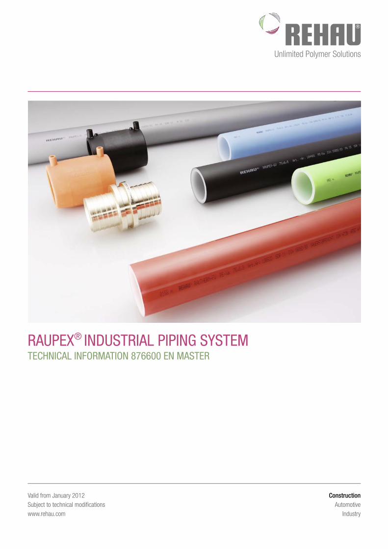
raupex® INDuSTrIaL pIpINg SYSTeMTeCHNICaL INFOrMaTION 876600 eN MaSTer
TabLe OF CONTeNTS
1 Information and safety information 5
2 Safety information 72.1 . . . . Applications . . . . . . . . . . . . . . . . . . . . . . . . . 72.2 . . . . Application limits . . . . . . . . . . . . . . . . . . . . . . . 72.3 . . . . Program components . . . . . . . . . . . . . . . . . . . . . 8
3 Pipes 93.1 . . . . Pipe raw materials . . . . . . . . . . . . . . . . . . . . . . 93.1.1 . . . Material properties . . . . . . . . . . . . . . . . . . . . . . 93.1.2 . . . Characteristic PE-Xa properties . . . . . . . . . . . . . . . . 93.1.3 . . . Chemical resistance . . . . . . . . . . . . . . . . . . . . . 93.2 . . . . Long-term rupture strength . . . . . . . . . . . . . . . . . 103.3 . . . . Pipe types . . . . . . . . . . . . . . . . . . . . . . . . . 113.3.1 . . . RAUPEX-A . . . . . . . . . . . . . . . . . . . . . . . . . 113.3.2 . . . RAUPEX-K . . . . . . . . . . . . . . . . . . . . . . . . . 113.3.3 . . . RAUPEX-O . . . . . . . . . . . . . . . . . . . . . . . . . 113.3.4 . . . RAUPEX-UV . . . . . . . . . . . . . . . . . . . . . . . . 113.3.5 . . . RAUTHERM-FW. . . . . . . . . . . . . . . . . . . . . . . 11
4 Compression sleeve joints 124.1 . . . . Metal compression sleeve joints . . . . . . . . . . . . . . . 124.1.1 . . . Compression sleeve joints processing information . . . . . . 124.1.2 . . . Description . . . . . . . . . . . . . . . . . . . . . . . . . 124.1.3 . . . Fitting materials . . . . . . . . . . . . . . . . . . . . . . 124.1.5 . . . Installation tools . . . . . . . . . . . . . . . . . . . . . . 134.1.6 . . . Creating 20 - 40 joints . . . . . . . . . . . . . . . . . . . 154.1.7 . . . Creating 40 - 110 joints . . . . . . . . . . . . . . . . . . 154.1.8 . . . Creating 125 - 160 joints . . . . . . . . . . . . . . . . . . 16
5 PE electrofusion fittings 175.1 . . . . General description . . . . . . . . . . . . . . . . . . . . . 175.2 . . . . Materials . . . . . . . . . . . . . . . . . . . . . . . . . . 175.3 . . . . Application limits . . . . . . . . . . . . . . . . . . . . . . 175.4 . . . . Installation tools . . . . . . . . . . . . . . . . . . . . . . 175.4.1 . . . Monomatic welding unit. . . . . . . . . . . . . . . . . . . 175.4.2 . . . Pipe cutter and rotary scraper . . . . . . . . . . . . . . . . 185.5 . . . . Creating joints . . . . . . . . . . . . . . . . . . . . . . . 195.6 . . . . Tapping clamp installation. . . . . . . . . . . . . . . . . . 215.7 . . . . Notes on welding with electrofusion fittings and tapping clamps 225.8 . . . . Branch saddle . . . . . . . . . . . . . . . . . . . . . . . 23
6 FUSAPEX electrofusion fittings made of PE-X 246.1 . . . . Processing requirements . . . . . . . . . . . . . . . . . . 246.2 . . . . Program components . . . . . . . . . . . . . . . . . . . . 246.2.1 . . . FUSAPEX electrofusion fitting . . . . . . . . . . . . . . . . 246.2.1.1 . . Description . . . . . . . . . . . . . . . . . . . . . . . . . 246.2.1.2 . . Characteristics . . . . . . . . . . . . . . . . . . . . . . . 246.2.1.3 . . FUSAPEX technical data. . . . . . . . . . . . . . . . . . . 246.2.1.4 . . Chemical resistance . . . . . . . . . . . . . . . . . . . . 246.2.1.5 . . Operating conditions classification in accordance with DIN EN
ISO 15875 . . . . . . . . . . . . . . . . . . . . . . . . . 256.2.2 . . . Installation tools . . . . . . . . . . . . . . . . . . . . . . 256.2.2.1 . . Monomatic welding unit. . . . . . . . . . . . . . . . . . . 256.2.2.2 . . Pipe cutter and rotary scraper . . . . . . . . . . . . . . . . 266.2.3 . . . FUSAPEX training certificate. . . . . . . . . . . . . . . . . 266.3 . . . . FUSAPEX electrofusion fitting joints . . . . . . . . . . . . . 276.3.1 . . . Tool preparation . . . . . . . . . . . . . . . . . . . . . . 27
6.3.2 . . . Pipe and fitting inspection. . . . . . . . . . . . . . . . . . 276.3.3 . . . Preparing pipe ends . . . . . . . . . . . . . . . . . . . . 276.3.4 . . . Connecting pipe ends using FUSAPEX . . . . . . . . . . . . 286.3.5 . . . Notes on welding with FUSAPEX electrofusion fittings . . . . 296.4 . . . . Shipping and storage . . . . . . . . . . . . . . . . . . . . 30
7 Pressure equipment directive 97/23/EC 31
8 Compressed air technology 328.1 . . . . General information . . . . . . . . . . . . . . . . . . . . . 328.2 . . . . Compressed air energy costs . . . . . . . . . . . . . . . . 328.3 . . . . Advantages of the RAUPEX industrial piping systems for
compressed air technology . . . . . . . . . . . . . . . . . 328.4 . . . . Compressed air quality . . . . . . . . . . . . . . . . . . . 328.4.1 . . . Quality classes for maximum particle sizes and maximum
particle numbers . . . . . . . . . . . . . . . . . . . . . . 328.4.2 . . . Water content quality classes . . . . . . . . . . . . . . . . 338.4.3 . . . Oil content quality classes. . . . . . . . . . . . . . . . . . 338.4.4 . . . Examples of compressed air quality classes . . . . . . . . . 338.5 . . . . Layout . . . . . . . . . . . . . . . . . . . . . . . . . . . 348.5.1 . . . Selecting operating pressure . . . . . . . . . . . . . . . . 348.5.2 . . . Calculating volume flow rate . . . . . . . . . . . . . . . . 348.5.3 . . . Establishing pipe length . . . . . . . . . . . . . . . . . . . 348.5.4 . . . Caclulating pressure drop . . . . . . . . . . . . . . . . . . 348.5.5 . . . Employment of a nomograph to determine the pipe diameter 358.5.6 . . . Compressed air for pipe dimension, SDR 11 . . . . . . . . . 368.5.7 . . . Compressed air for pipe dimension, SDR 7.4 . . . . . . . . 378.6 . . . . Application examples . . . . . . . . . . . . . . . . . . . . 388.6.1 . . . Ball valve . . . . . . . . . . . . . . . . . . . . . . . . . . 388.6.2 . . . 3-way compressed air manifold . . . . . . . . . . . . . . . 38
9 Chilled water systems 399.1 . . . . General information . . . . . . . . . . . . . . . . . . . . . 399.2 . . . . Design . . . . . . . . . . . . . . . . . . . . . . . . . . . 399.2.1 . . . Template for pressure loss calculation . . . . . . . . . . . . 409.2.2 . . . Pressure loss calculation example . . . . . . . . . . . . . . 409.2.3 . . . Chilled water, SDR 11. . . . . . . . . . . . . . . . . . . . 419.2.4 . . . Chilled water, SDR 7.4 . . . . . . . . . . . . . . . . . . . 429.2.5 . . . Pressure loss template . . . . . . . . . . . . . . . . . . . 43
10 Solid particle transport 4410.1. . . . Hydraulic solids transport . . . . . . . . . . . . . . . . . . 4410.2. . . . Pneumatic solids transport . . . . . . . . . . . . . . . . . 44
11 Assembly and installation 4511.1. . . . Subsoil installation . . . . . . . . . . . . . . . . . . . . . 4511.1.1. . . Subsoil work . . . . . . . . . . . . . . . . . . . . . . . . 4511.1.2. . . Pipe inspection . . . . . . . . . . . . . . . . . . . . . . . 4511.1.3. . . Special considerations when working with coils . . . . . . . 4511.1.4. . . Minimum deflection radii during subsoil installation . . . . . 4511.1.5. . . Backfilling the trench . . . . . . . . . . . . . . . . . . . . 4511.2. . . . Empty pipe installation . . . . . . . . . . . . . . . . . . . 4611.3. . . . Cable duct installation . . . . . . . . . . . . . . . . . . . 4611.4. . . . Installation in conjunction with cable carrier systems . . . . . 4611.4.1. . . Cable carrier system installation. . . . . . . . . . . . . . . 4611.4.2. . . Installation below or beside cable carrier systems . . . . . . 4611.5. . . . Open installation in pipe support channels . . . . . . . . . . 4611.5.1. . . Deflection leg installation in pipe support channels . . . . . . 46
2
11.5.2. . . Deflection leg calculation . . . . . . . . . . . . . . . . . . 4711.5.3. . . Calculation example . . . . . . . . . . . . . . . . . . . . 4711.5.4. . . Deflection leg determination from a diagram . . . . . . . . . 4711.6. . . . Surface mounted installation without pipe support channels . 5111.6.1. . . Installation of deflection legs . . . . . . . . . . . . . . . . 5111.6.2. . . Pre-stressed installation technique . . . . . . . . . . . . . 53
12 REHAU pipe clips 5412.1. . . . Pipe clips w./without retaining clip. . . . . . . . . . . . . . 54
13 Pipe identification 5613.1. . . . Identification colors . . . . . . . . . . . . . . . . . . . . . 5613.2. . . . Adhesive labels . . . . . . . . . . . . . . . . . . . . . . . 56
14 Fire protection 5714.1. . . . Thermal load . . . . . . . . . . . . . . . . . . . . . . . . 5714.2. . . . Fireproofing collars . . . . . . . . . . . . . . . . . . . . . 57
15 Practical examples 58
16 Pressure test report / copy template 59
17 Standards, regulations, directives 60
3
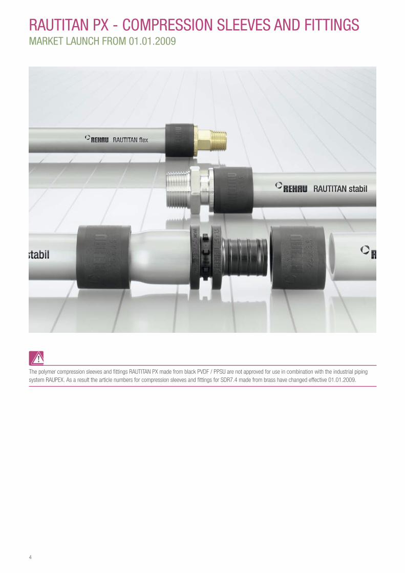
rauTITaN px - COMpreSSION SLeeVeS aND FITTINgSMarKeT LauNCH FrOM 01.01.2009
The polymer compression sleeves and fittings RAUTITAN PX made from black PVDF / PPSU are not approved for use in combination with the industrial piping system RAUPEX. As a result the article numbers for compression sleeves and fittings for SDR7.4 made from brass have changed effective 01.01.2009.
4
Notes on this Technical Information
ValidityThis technical information applies to (country).
NavigationAt the beginning of this technical information, you can find a detailed Table of contents with hierarchical titles and corresponding page numbers.
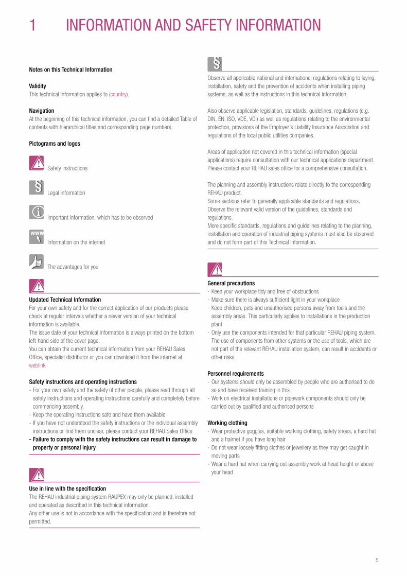
Pictograms and logos
Safety instructions
Legal information
Important information, which has to be observed
Information on the internet
The advantages for you
Updated Technical InformationFor your own safety and for the correct application of our products please check at regular intervals whether a newer version of your technical information is available. The issue date of your technical information is always printed on the bottom left-hand side of the cover page. You can obtain the current technical information from your REHAU Sales Office, specialist distributor or you can download it from the internet at weblink
Safety instructions and operating instructions - For your own safety and the safety of other people, please read through all safety instructions and operating instructions carefully and completely before commencing assembly.
- Keep the operating instructions safe and have them available - If you have not understood the safety instructions or the individual assembly instructions or find them unclear, please contact your REHAU Sales Office
- Failure to comply with the safety instructions can result in damage to property or personal injury
Use in line with the specificationThe REHAU industrial piping system RAUPEX may only be planned, installed and operated as described in this technical information. Any other use is not in accordance with the specification and is therefore not permitted.
1 INFOrMaTION aND SaFeTY INFOrMaTION
Observe all applicable national and international regulations relating to laying, installation, safety and the prevention of accidents when installing piping systems, as well as the instructions in this technical information.
Also observe applicable legislation, standards, guidelines, regulations (e.g. DIN, EN, ISO, VDE, VDI) as well as regulations relating to the environmental protection, provisions of the Employer’s Liability Insurance Association and regulations of the local public utilities companies.
Areas of application not covered in this technical information (special applications) require consultation with our technical applications department. Please contact your REHAU sales office for a comprehensive consultation.
The planning and assembly instructions relate directly to the corresponding REHAU product. Some sections refer to generally applicable standards and regulations. Observe the relevant valid version of the guidelines, standards and regulations. More specific standards, regulations and guidelines relating to the planning, installation and operation of industrial piping systems must also be observed and do not form part of this Technical Information.
General precautions - Keep your workplace tidy and free of obstructions - Make sure there is always sufficient light in your workplace - Keep children, pets and unauthorised persons away from tools and the assembly areas. This particularly applies to installations in the production plant
- Only use the components intended for that particular REHAU piping system. The use of components from other systems or the use of tools, which are not part of the relevant REHAU installation system, can result in accidents or other risks.
Personnel requirements - Our systems should only be assembled by people who are authorised to do so and have received training in this
- Work on electrical installations or pipework components should only be carried out by qualified and authorised persons
Working clothing - Wear protective goggles, suitable working clothing, safety shoes, a hard hat and a hairnet if you have long hair
- Do not wear loosely fitting clothes or jewellery as they may get caught in moving parts
- Wear a hard hat when carrying out assembly work at head height or above your head
5
During assembly - Always read and follow the operating instructions for the REHAU assembly tool used
- Improper handling of tools can result in severe cuts, trapped or severed limbs
- Improper handling of tools can damage the jointing components and result in leaks
- The REHAU pipe cutters have a sharp blade. Store and handle them in such a way that there is no risk of injury from the pipe cutters
- When trimming the pipes, maintain a safe distance between the hand holding the pipe and the cutting tool
- Never put your hand in the tool‘s cutting zone or on moving parts during the cutting process
- Following the expansion process, the expanded pipe shrinks back to its original shape (memory effect). Do not insert any foreign objects into the expanded pipe during this stage
- Never put your hand in the tool‘s compression zone or on moving parts during the compression process
- Until the connection is established following the compression process, the fitting can fall out of the pipe. There is a risk of injury!
- During maintenance or retooling work and when changing the assembly area, always unplug the tool and prevent it from being switched on accidentally
Operating parameters - If the operating parameters are exceeded, excessive stress is placed on the pipes and connections. It is therefore not permissible to exceed the operating parameters
- It is to be ensured that the operating parameters are adhered to by means of safety / regulation devices (e.g. reducing regulator, safety valves or similar equipment)
6
2 SaFeTY INFOrMaTION
Increasingly, RAUPEX industrial piping systems are being used for a wide variety of applications in a number of industrial areas, such as the automotive, chemical and public utilities sectors.Their fast and safe installation, corrosion resistance, lightweight pipe material and the associated low installation cost all prove that RAUPEX is capable of uniting numerous advantages to create a single system.The RAUPEX industrial piping systems meets industry demand for safe and total system solutions. It offers a wide range of differently colored pipes, together with products such as fittings, tools and other accessories, all of which are described in greater detail in this technical information.
2 1 ApplicationsWithin the context of the approved application limits with respect to pressure, temperature and chemical resistance described in this technical information for the pipes and fittings, the RAUPEX industrial piping systems is suitable for industrial gases, liquids and solid particles.
Typical industrial pipe applications for which the RAUPEX industrial piping systems has proven itself include: - Compressed air; - Vacuum; - Inert gases; - Cooling water; - Process water; - Cold transport (not coolants!); - Conveying solid particles
RAUPEX has not been approved for applications requiring special system authorization such as the transport of natural gas, liquefied gas, flammable gases, potable water, food products and similar materials, nor for use in fire extinguishing systems.For these types of applications, REHAU maintains several specially developed systems in its product range.
2 2 Application limitsThe application limits for each system component with respect to pressure and temperature have been summarized under the following headings in this documentation: - Pipes: Table 3, in Section 3.2 - PE electrofusion fittings: Table 4, in Section 5.3 - FUSAPEX electrofusion fittings: Table 11 through 14, in Section 6.2.1.5
For information regarding chemical resistance, please refer to Section 3.1.3.
The responsibility for checking the suitability of REHAU products for the intended applications lies with the consultant or installer, because only they know the exact operating and boundary conditions.
7
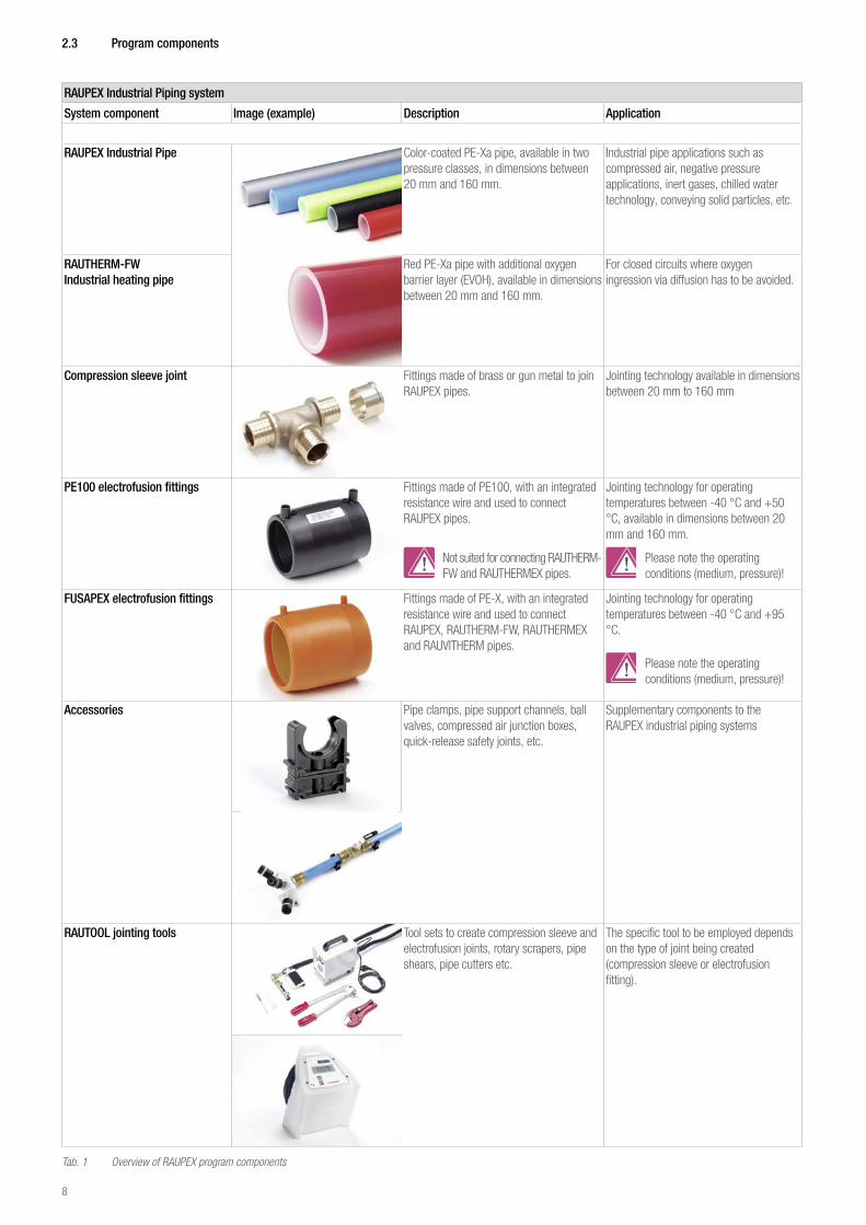
2 3 Program components
RAUPEX Industrial Piping system
System component Image (example) Description Application
RAUPEX Industrial Pipe Color-coated PE-Xa pipe, available in two pressure classes, in dimensions between 20 mm and 160 mm.
Industrial pipe applications such as compressed air, negative pressure applications, inert gases, chilled water technology, conveying solid particles, etc.
RAUTHERM-FW Industrial heating pipe
Red PE-Xa pipe with additional oxygen barrier layer (EVOH), available in dimensions between 20 mm and 160 mm.
For closed circuits where oxygen ingression via diffusion has to be avoided.
Compression sleeve joint Fittings made of brass or gun metal to join RAUPEX pipes.
Jointing technology available in dimensions between 20 mm to 160 mm
PE100 electrofusion fittings
Fittings made of PE100, with an integrated resistance wire and used to connect RAUPEX pipes.
Not suited for connecting RAUTHERM-FW and RAUTHERMEX pipes.
Jointing technology for operating temperatures between -40 °C and +50 °C, available in dimensions between 20 mm and 160 mm.
Please note the operating conditions (medium, pressure)!
FUSAPEX electrofusion fittings Fittings made of PE-X, with an integrated resistance wire and used to connect RAUPEX, RAUTHERM-FW, RAUTHERMEX and RAUVITHERM pipes.
Jointing technology for operating temperatures between -40 °C and +95 °C.
Please note the operating conditions (medium, pressure)!
Accessories Pipe clamps, pipe support channels, ball valves, compressed air junction boxes, quick-release safety joints, etc.
Supplementary components to the RAUPEX industrial piping systems
RAUTOOL jointing tools Tool sets to create compression sleeve and electrofusion joints, rotary scrapers, pipe shears, pipe cutters etc.
The specific tool to be employed depends on the type of joint being created (compression sleeve or electrofusion fitting).
Tab. 1 Overview of RAUPEX program components
8
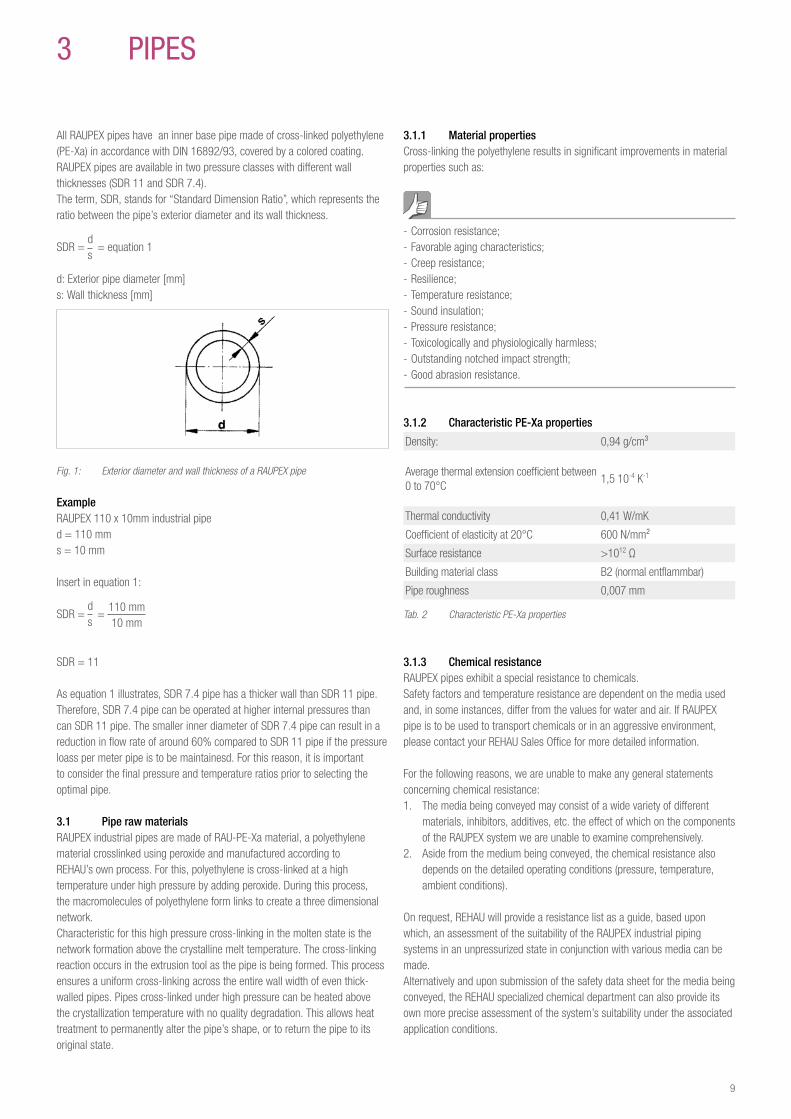
All RAUPEX pipes have an inner base pipe made of cross-linked polyethylene (PE-Xa) in accordance with DIN 16892/93, covered by a colored coating. RAUPEX pipes are available in two pressure classes with different wall thicknesses (SDR 11 and SDR 7.4).The term, SDR, stands for “Standard Dimension Ratio”, which represents the ratio between the pipe’s exterior diameter and its wall thickness.
SDR = ds
= equation 1
d: Exterior pipe diameter [mm]s: Wall thickness [mm]
Fig. 1: Exterior diameter and wall thickness of a RAUPEX pipe
ExampleRAUPEX 110 x 10mm industrial piped = 110 mms = 10 mm
Insert in equation 1:
SDR = ds
= 110 mm10 mm
SDR = 11
As equation 1 illustrates, SDR 7.4 pipe has a thicker wall than SDR 11 pipe. Therefore, SDR 7.4 pipe can be operated at higher internal pressures than can SDR 11 pipe. The smaller inner diameter of SDR 7.4 pipe can result in a reduction in flow rate of around 60% compared to SDR 11 pipe if the pressure loass per meter pipe is to be maintainesd. For this reason, it is important to consider the final pressure and temperature ratios prior to selecting the optimal pipe.
3 1 Pipe raw materialsRAUPEX industrial pipes are made of RAU-PE-Xa material, a polyethylene material crosslinked using peroxide and manufactured according to REHAU’s own process. For this, polyethylene is cross-linked at a high temperature under high pressure by adding peroxide. During this process, the macromolecules of polyethylene form links to create a three dimensional network.Characteristic for this high pressure cross-linking in the molten state is the network formation above the crystalline melt temperature. The cross-linking reaction occurs in the extrusion tool as the pipe is being formed. This process ensures a uniform cross-linking across the entire wall width of even thick-walled pipes. Pipes cross-linked under high pressure can be heated above the crystallization temperature with no quality degradation. This allows heat treatment to permanently alter the pipe’s shape, or to return the pipe to its original state.
3 pIpeS
3 1 1 Material propertiesCross-linking the polyethylene results in significant improvements in material properties such as:
- Corrosion resistance; - Favorable aging characteristics; - Creep resistance; - Resilience; - Temperature resistance; - Sound insulation; - Pressure resistance; - Toxicologically and physiologically harmless; - Outstanding notched impact strength; - Good abrasion resistance.
3 1 2 Characteristic PE-Xa properties
Density: 0,94 g/cm³
Average thermal extension coefficient between 0 to 70°C
1,5 10-4 K-1
Thermal conductivity 0,41 W/mK
Coefficient of elasticity at 20°C 600 N/mm²
Surface resistance >1012 Ω
Building material class B2 (normal entflammbar)
Pipe roughness 0,007 mm
Tab. 2 Characteristic PE-Xa properties
3 1 3 Chemical resistanceRAUPEX pipes exhibit a special resistance to chemicals.Safety factors and temperature resistance are dependent on the media used and, in some instances, differ from the values for water and air. If RAUPEX pipe is to be used to transport chemicals or in an aggressive environment, please contact your REHAU Sales Office for more detailed information.
For the following reasons, we are unable to make any general statements concerning chemical resistance:1. The media being conveyed may consist of a wide variety of different
materials, inhibitors, additives, etc. the effect of which on the components of the RAUPEX system we are unable to examine comprehensively.
2. Aside from the medium being conveyed, the chemical resistance also depends on the detailed operating conditions (pressure, temperature, ambient conditions).
On request, REHAU will provide a resistance list as a guide, based upon which, an assessment of the suitability of the RAUPEX industrial piping systems in an unpressurized state in conjunction with various media can be made.Alternatively and upon submission of the safety data sheet for the media being conveyed, the REHAU specialized chemical department can also provide its own more precise assessment of the system’s suitability under the associated application conditions.
9
Consultants or installer are responsible for verifying the suitability of REHAU products for the specific intended application, as only they know the installation specific detailed operating and boundary conditions.If an approval is required, it is to be obtained from the manufacturer of the medium being conveyed, because they know the exact chemical composition of the medium. The necessary material information related to the RAUPEX industrial piping systems components are given in this Technical Information.
For questions regarding the chemical resistance, please contact the manufacturer of the medium to be caonveyed.
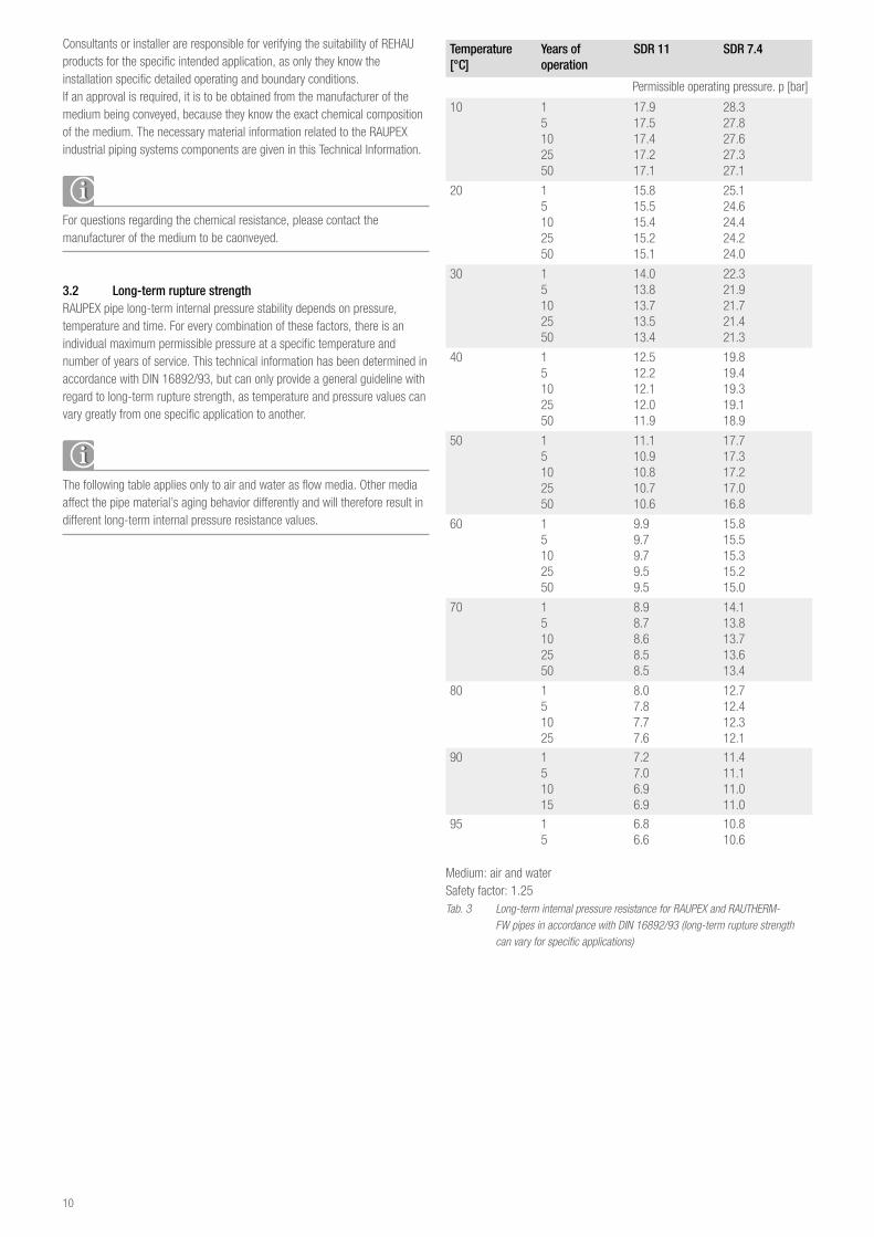
3 2 Long-term rupture strengthRAUPEX pipe long-term internal pressure stability depends on pressure, temperature and time. For every combination of these factors, there is an individual maximum permissible pressure at a specific temperature and number of years of service. This technical information has been determined in accordance with DIN 16892/93, but can only provide a general guideline with regard to long-term rupture strength, as temperature and pressure values can vary greatly from one specific application to another.
The following table applies only to air and water as flow media. Other media affect the pipe material’s aging behavior differently and will therefore result in different long-term internal pressure resistance values.
Temperature[°C]
Years of operation
SDR 11 SDR 7 4
Permissible operating pressure. p [bar]
10 15102550
17.917.517.417.217.1
28.327.827.627.327.1
20 15102550
15.815.515.415.215.1
25.124.624.424.224.0
30 15102550
14.013.813.713.513.4
22.321.921.721.421.3
40 15102550
12.512.212.112.011.9
19.819.419.319.118.9
50 15102550
11.110.910.810.710.6
17.717.317.217.016.8
60 15102550
9.99.79.79.59.5
15.815.515.315.215.0
70 15102550
8.98.78.68.58.5
14.113.813.713.613.4
80 151025
8.07.87.77.6
12.712.412.312.1
90 151015
7.27.06.96.9
11.411.111.011.0
95 15
6.86.6
10.810.6
Medium: air and waterSafety factor: 1.25Tab. 3 Long-term internal pressure resistance for RAUPEX and RAUTHERM- FW pipes in accordance with DIN 16892/93 (long-term rupture strength can vary for specific applications)
10
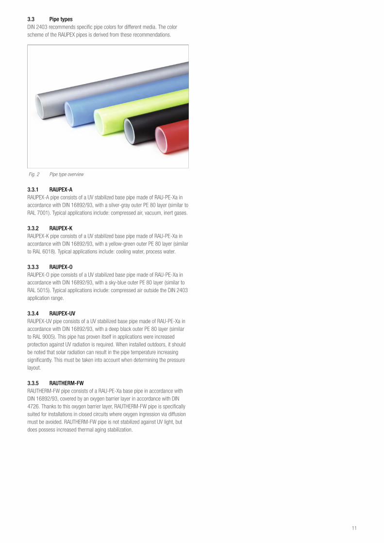
3 3 Pipe typesDIN 2403 recommends specific pipe colors for different media. The color scheme of the RAUPEX pipes is derived from these recommendations.
Fig. 2 Pipe type overview
3 3 1 RAUPEX-ARAUPEX-A pipe consists of a UV stabilized base pipe made of RAU-PE-Xa in accordance with DIN 16892/93, with a silver-gray outer PE 80 layer (similar to RAL 7001). Typical applications include: compressed air, vacuum, inert gases.
3 3 2 RAUPEX-KRAUPEX-K pipe consists of a UV stabilized base pipe made of RAU-PE-Xa in accordance with DIN 16892/93, with a yellow-green outer PE 80 layer (similar to RAL 6018). Typical applications include: cooling water, process water.
3 3 3 RAUPEX-ORAUPEX-O pipe consists of a UV stabilized base pipe made of RAU-PE-Xa in accordance with DIN 16892/93, with a sky-blue outer PE 80 layer (similar to RAL 5015). Typical applications include: compressed air outside the DIN 2403 application range. 3 3 4 RAUPEX-UVRAUPEX-UV pipe consists of a UV stabilized base pipe made of RAU-PE-Xa in accordance with DIN 16892/93, with a deep black outer PE 80 layer (similar to RAL 9005). This pipe has proven itself in applications were increased protection against UV radiation is required. When installed outdoors, it should be noted that solar radiation can result in the pipe temperature increasing significantly. This must be taken into account when determining the pressure layout.
3 3 5 RAUTHERM-FWRAUTHERM-FW pipe consists of a RAU-PE-Xa base pipe in accordance with DIN 16892/93, covered by an oxygen barrier layer in accordance with DIN 4726. Thanks to this oxygen barrier layer, RAUTHERM-FW pipe is specifically suited for installations in closed circuits where oxygen ingression via diffusion must be avoided. RAUTHERM-FW pipe is not stabilized against UV light, but does possess increased thermal aging stabilization.
11
4 COMpreSSION SLeeVe JOINTS
4 1 Metal compression sleeve joints
4 1 1 Compression sleeve joints processing information
Risk of using incorrect fi ttings - Check the dimensions given on the fi ttings. They must match the dimensions printed on the pipe.
- Consult the most current price list to correctly match the fi tting type with the suitable pipe type.
Avoiding corrosion damage - Prior to coming into contact with masonry or screed, cement, plaster, quick-contact bonding agent, aggressive media and other corrosion-producing materials, protect fi ttings and compression sleeves by wrapping them with a suitable cover .
- In aggressive environments (e.g., animal cages, cast in concrete, marine environments, cleaners), ensure that pipes and fi ttings have adequate protection with a diff usion barrier against corrosion (e.g., against aggressive gases, fermentation gases).
- Protect fi ttings, pipes and compression sleeves against moisture. - Make sure the used sealants, cleaners, installation foams, etc. do not contain ingredients which could subsequently result in stress corrosion failures, e.g., ammonia, ingredients containing ammonia.
Avoiding contamination and damage - Never use any dirty or damaged system components, pipes, fi ttings, compression sleeve or seals.
- Prior to reconnecting joints with fl at seals (or similar seals) always inspect the sealing surfaces for any damage and, if required, replace the seal with a new one.
Using appropriate adjusting toolsUse only the appropriate adjusting tools such as pipe nipples or spanners to align fi ttings.
REHAU installation tools - Prior to using REHAU tools, please carefully read and comply with their specifi c operating instructions.
- Should the operating instructions for a specifi c tool be missing or no longer be available, please request a copy.
- Do not employ damaged tools or tools with limited function. Such tools should be returned to the associated REHAU Sales Offi ce.
- Comply with all maintenance instructions contained in the individual tool’s operating instructions.
Avoid excessive installation loads - Avoid over-tightening threaded joints. - Employ only spanners of correct size . Do not over-tighten fi ttings using a vice.
- The use of pipe wrenches may result in damage to fi ttings. - Avoid excessive hemp on the threaded joints. The thread pitches must remain recognizable.
- Do not deform fi ttings, e.g., by hitting them with a hammer. - Employ only threads in accordance with ISO 7-1, DIN EN 10226-1 and ISO 228. Other thread types are prohibited.
Working with threaded fi ttings - Employ only approved sealants (e.g., sealants certifi ed by the DVGW). - Do not add extensions to the installation tool lever arm, e.g., through the use of pipe sections.
- Join threaded connections so that the thread outlet (on the end of the thread) remains visible.
- Prior to joining diff erent thread types (in accordance with ISO 7-1, DIN EN 10226-1 and ISO 228), examine the tolerance position, ease of threading, etc.
- Other thread types are prohibited. - When employing long-threads, note the maximum possible penetration depth and check for adequate thread depth in the opposite internal thread.
Threads for fi ttings with a thread transition are designed as follows: - Thread in accordance with ISO 7-1 and DIN EN 10226-1:
- Rp = Cylindrical internal thread - R = Conical external thread
- Thread in accordance with ISO 228: - G = Cylindrical thread, non-sealing in the thread
As a system supplement, REHAU recommends screw fi ttings made of dezincifi cation-resistant brass or gun metal.
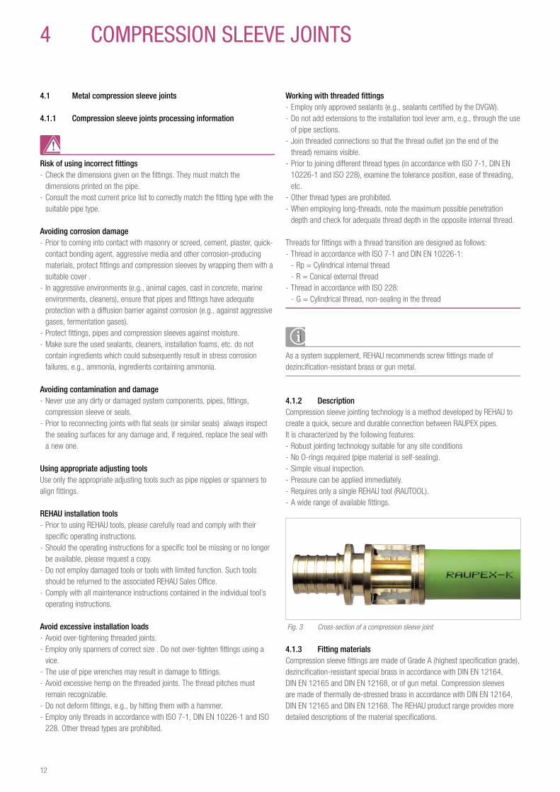
4 1 2 DescriptionCompression sleeve jointing technology is a method developed by REHAU to create a quick, secure and durable connection between RAUPEX pipes.It is characterized by the following features: - Robust jointing technology suitable for any site conditions - No O-rings required (pipe material is self-sealing). - Simple visual inspection. - Pressure can be applied immediately. - Requires only a single REHAU tool (RAUTOOL). - A wide range of available fi ttings.
Fig. 3 Cross-section of a compression sleeve joint
4 1 3 Fitting materialsCompression sleeve fi ttings are made of Grade A (highest specifi cation grade), dezincifi cation-resistant special brass in accordance with DIN EN 12164, DIN EN 12165 and DIN EN 12168, or of gun metal. Compression sleeves are made of thermally de-stressed brass in accordance with DIN EN 12164, DIN EN 12165 and DIN EN 12168. The REHAU product range provides more detailed descriptions of the material specifi cations.
12
4 1 5 Installation toolsREHAU offers installers a variety of compression sleeve installation tools. The various tool types allow the installer to select the optimum tool for every application. All compression sleeve tools have been designed to fully meet on-site demands. It only remains for the installer to decide which tool offers the optimal solution for his specific application.
Operating instructions for REHAU tools can be downloaded from the Internet at weblink.
The scope of the RAUTOOL installation tools can be found in the price list for RAUPEX industrial piping systems.
RAUTOOL M1
Fig. 4 RAUTOOL M1
- Manual tool - Application range: dimensions between 16 - 40
The hydraulic tools RAUTOOL H2, RAUTOOL E2/E3 and RAUTOOL A2/A3/A-light/A-light2 are mutually compatible and can therefore be equipped with the same supplementary sets. Expanding pliers and expander heads from the RO expander system are mutually compatible up to the dimension 40.RAUTOOL H2
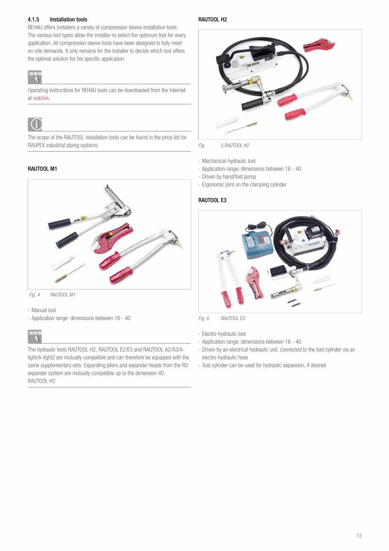
RAUTOOL H2
Fig. 5 RAUTOOL H2
- Mechanical-hydraulic tool - Application range: dimensions between 16 - 40 - Driven by hand/foot pump - Ergonomic joint on the clamping cylinder
RAUTOOL E3
Fig. 6 RAUTOOL E3
- Electro-hydraulic tool - Application range: dimensions between 16 - 40 - Driven by an electrical hydraulic unit, connected to the tool cylinder via an electro-hydraulic hose
- Tool cylinder can be used for hydraulic expansion, if desired
13
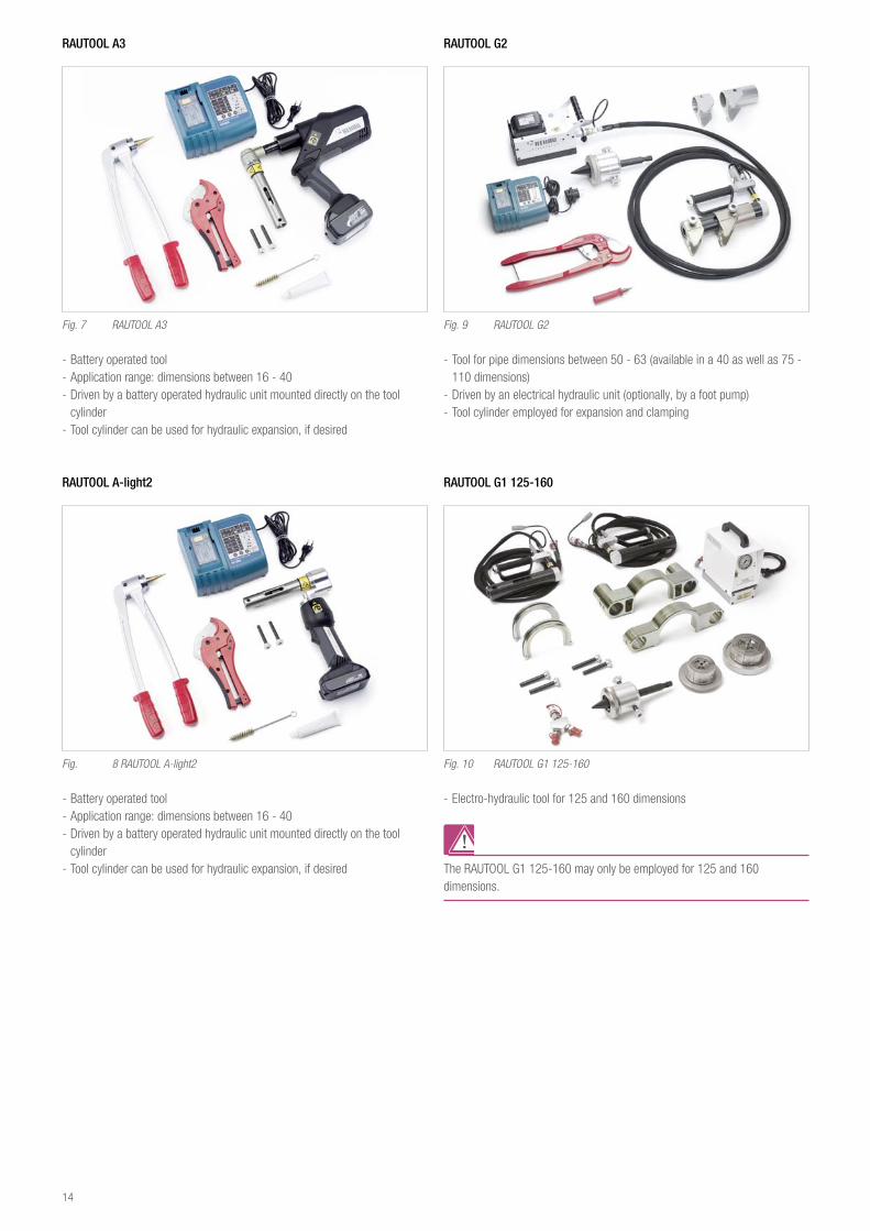
RAUTOOL A3
Fig. 7 RAUTOOL A3
- Battery operated tool - Application range: dimensions between 16 - 40 - Driven by a battery operated hydraulic unit mounted directly on the tool cylinder
- Tool cylinder can be used for hydraulic expansion, if desired
RAUTOOL A-light2
Fig. 8 RAUTOOL A-light2
- Battery operated tool - Application range: dimensions between 16 - 40 - Driven by a battery operated hydraulic unit mounted directly on the tool cylinder
- Tool cylinder can be used for hydraulic expansion, if desired
RAUTOOL G2
Fig. 9 RAUTOOL G2
- Tool for pipe dimensions between 50 - 63 (available in a 40 as well as 75 - 110 dimensions)
- Driven by an electrical hydraulic unit (optionally, by a foot pump) - Tool cylinder employed for expansion and clamping
RAUTOOL G1 125-160
Fig. 10 RAUTOOL G1 125-160
- Electro-hydraulic tool for 125 and 160 dimensions
The RAUTOOL G1 125-160 may only be employed for 125 and 160 dimensions.
14
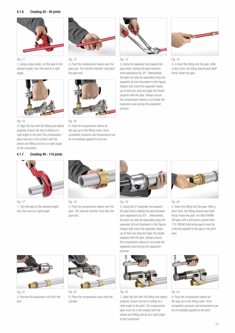
4 1 6 Creating 20 - 40 joints
Fig. 11
1. Using a pipe cutter, cut the pipe to the desired length, burr-free and at a right angle.
Fig. 12
2. Push the compression sleeve over the pipe end. The internal chamfer must face the pipe end.
Fig. 13
3. Using the expander tool expand the pipe twice rotating the pipe between both expansions by 30°. Alternatively, the pipe can also be expanded using the expander bit (not illustrated in the Figure). Always fully insert the expander heads up to their pre-stop and align the heads properly with the pipe. Always ensure the compression sleeve is not inside the expansion area during the expansion process.
Fig. 14
4. 4.Insert the fitting into the pipe. After a short time, the fitting should seat itself firmly inside the pipe.
Fig. 15
5. Align the tool with the fitting and sleeve properly. Ensure the tool is sitting at a right angle to the joint.The compression jaws must be in full contact with the sleeve and fitting and be at a right angle to the connection.
Fig. 16
6. Push the compression sleeve all the way up to the fitting collar. Once completed, pressure and temperature can be immediately applied to the joint.
Fig. 17
1. Trim the pipe to the desired length, burr-free and at a right angle.
Fig. 18
2. Push the compression sleeve over the pipe. The internal chamfer must face the pipe end.
Fig. 19
3. Using the G1 expander tool expand the pipe twice rotating the pipe between both expansions by 30°. . Alternatively, the pipe can also be expanded using the expander bit (not illustrated in the Figure). Always fully insert the expander heads up to their pre-stop and align the heads properly with the pipe. Always ensure the compression sleeve is not inside the expansion area during the expansion process.
Fig. 20
4. Insert the fitting into the pipe. After a short time, the fitting should seat itself firmly inside the pipe. For RAUTHERM-FW pipe with a dimension greater than 110, REHAU lubricating agent must be uniformly applied to the pipe in the joint area.
Fig. 21
5. Remove the expansion unit from the tool.
Fig. 22
6. Place the compression jaws onto the cylinder.
Fig. 23
7. Align the tool with the fitting and sleeve properly. Ensure the tool is sitting at a right angle to the joint. The compression jaws must be in full contact with the sleeve and fitting and be at a right angle to the connection.
Fig. 24
8. Push the compression sleeve all the way up to the fitting collar. Once completed, pressure and temperature can be immediately applied to the joint.
4 1 7 Creating 40 - 110 joints
15
4 1 8 Creating 125 - 160 joints
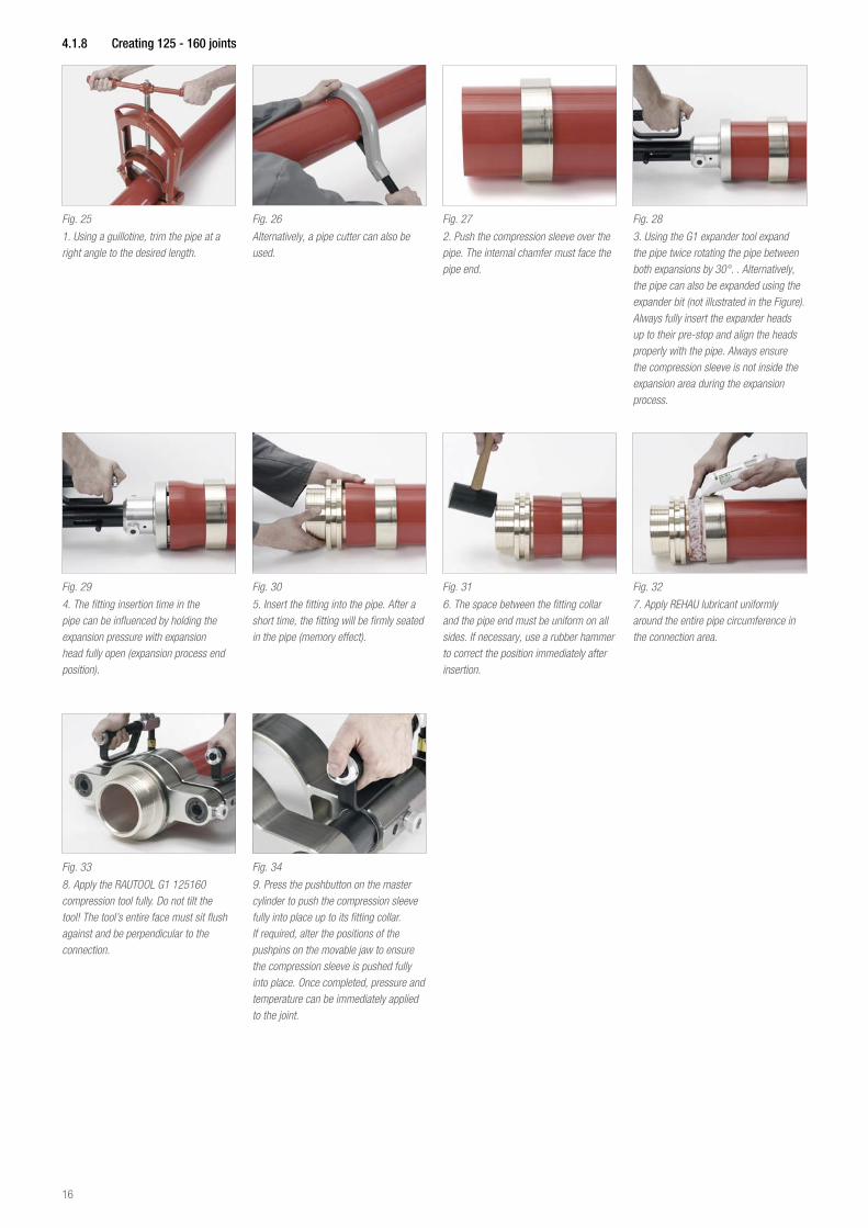
Fig. 25
1. Using a guillotine, trim the pipe at a right angle to the desired length.
Fig. 26
Alternatively, a pipe cutter can also be used.
Fig. 27
2. Push the compression sleeve over the pipe. The internal chamfer must face the pipe end.
Fig. 28
3. Using the G1 expander tool expand the pipe twice rotating the pipe between both expansions by 30°. . Alternatively, the pipe can also be expanded using the expander bit (not illustrated in the Figure). Always fully insert the expander heads up to their pre-stop and align the heads properly with the pipe. Always ensure the compression sleeve is not inside the expansion area during the expansion process.
Fig. 29
4. The fitting insertion time in the pipe can be influenced by holding the expansion pressure with expansion head fully open (expansion process end position).
Fig. 30
5. Insert the fitting into the pipe. After a short time, the fitting will be firmly seated in the pipe (memory effect).
Fig. 31
6. The space between the fitting collar and the pipe end must be uniform on all sides. If necessary, use a rubber hammer to correct the position immediately after insertion.
Fig. 32
7. Apply REHAU lubricant uniformly around the entire pipe circumference in the connection area.
Fig. 33
8. Apply the RAUTOOL G1 125160 compression tool fully. Do not tilt the tool! The tool’s entire face must sit flush against and be perpendicular to the connection.
Fig. 34
9. Press the pushbutton on the master cylinder to push the compression sleeve fully into place up to its fitting collar. If required, alter the positions of the pushpins on the movable jaw to ensure the compression sleeve is pushed fully into place. Once completed, pressure and temperature can be immediately applied to the joint.
16
5 pe eLeCTrOFuSION FITTINgS
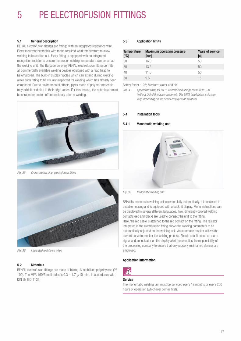
5 1 General descriptionREHAU electrofusion fittings are fittings with an integrated resistance wire. Electric current heats this wire to the required weld temperature to allow welding to be carried out. Every fitting is equipped with an integrated recognition resistor to ensure the proper welding temperature can be set at the welding unit. The Barcode on every REHAU electrofusion fitting permits all commercially available welding devices equipped with a read head to be employed. The built-in display nipples which can extend during welding allow each fitting to be visually inspected for welding which has already been completed. Due to environmental effects, pipes made of polymer materials may exhibit oxidation in their edge zones. For this reason, the outer layer must be scraped or peeled off immediately prior to welding.
Fig. 35 Cross-section of an electrofusion fitting
Fig. 36 Integrated resistance wires
5 2 MaterialsREHAU electrofusion fittings are made of black, UV-stabilized polyethylene (PE 100). The MFR 190/5 melt index is 0.3 – 1.7 g/10 min., in accordance with DIN EN ISO 1133.
5 3 Application limits
Temperature [°C]
Maximum operating pressure [bar]
Years of service [a]
20 16.0 50
30 13.5 50
40 11.6 50
50 9.5 15
Safety factor 1.25; Medium: water and airTab. 4 Application limits for PN16 electrofusion fittings made of PE100 (without LightFit) in accordance with DIN 8075 (application limits can vary, depending on the actual employment situation)
5 4 Installation tools
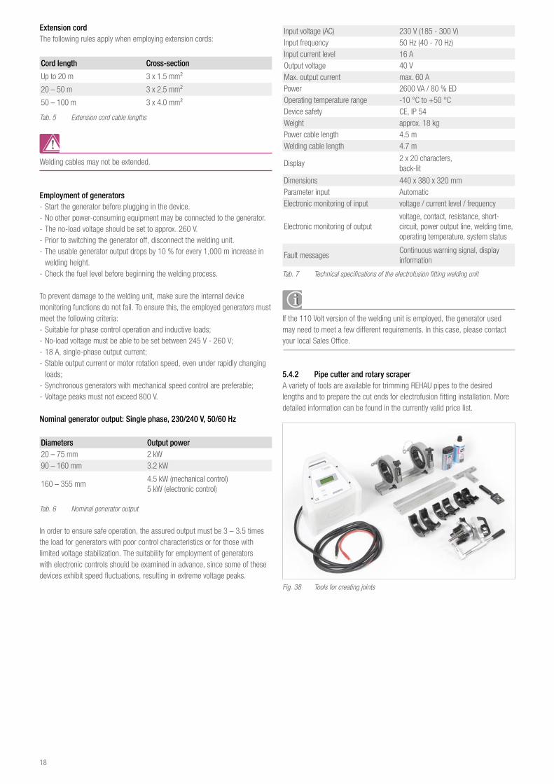
5 4 1 Monomatic welding unit
Fig. 37 Monomatic welding unit
REHAU’s monomatic welding unit operates fully automatically. It is enclosed in a stable housing and is equipped with a back-lit display. Menu instructions can be displayed in several different languages. Two, differently colored welding contacts (red and black) are used to connect the unit to the fitting.Here, the red cable is attached to the red contact on the fitting. The resistor integrated in the electrofusion fitting allows the welding parameters to be automatically adjusted on the welding unit. An automatic monitor utilizes the current curve to monitor the welding process. Should a fault occur, an alarm signal and an indicator on the display alert the user. It is the responsibility of the processing company to ensure that only properly maintained devices are employed.
Application information
ServiceThe monomatic welding unit must be serviced every 12 months or every 200 hours of operation (whichever comes first).
17
Extension cordThe following rules apply when employing extension cords:
Cord length Cross-section
Up to 20 m 3 x 1.5 mm²
20 – 50 m 3 x 2.5 mm²
50 – 100 m 3 x 4.0 mm²
Tab. 5 Extension cord cable lengths
Welding cables may not be extended.
Employment of generators - Start the generator before plugging in the device. - No other power-consuming equipment may be connected to the generator. - The no-load voltage should be set to approx. 260 V. - Prior to switching the generator off, disconnect the welding unit. - The usable generator output drops by 10 % for every 1,000 m increase in welding height.
- Check the fuel level before beginning the welding process.
To prevent damage to the welding unit, make sure the internal device monitoring functions do not fail. To ensure this, the employed generators must meet the following criteria: - Suitable for phase control operation and inductive loads; - No-load voltage must be able to be set between 245 V - 260 V; - 18 A, single-phase output current; - Stable output current or motor rotation speed, even under rapidly changing loads;
- Synchronous generators with mechanical speed control are preferable; - Voltage peaks must not exceed 800 V.
Nominal generator output: Single phase, 230/240 V, 50/60 Hz
Diameters Output power20 – 75 mm 2 kW90 – 160 mm 3.2 kW
160 – 355 mm4.5 kW (mechanical control)5 kW (electronic control)
Tab. 6 Nominal generator output
In order to ensure safe operation, the assured output must be 3 – 3.5 times the load for generators with poor control characteristics or for those with limited voltage stabilization. The suitability for employment of generators with electronic controls should be examined in advance, since some of these devices exhibit speed fluctuations, resulting in extreme voltage peaks.
Input voltage (AC) 230 V (185 - 300 V)Input frequency 50 Hz (40 - 70 Hz)Input current level 16 AOutput voltage 40 VMax. output current max. 60 APower 2600 VA / 80 % EDOperating temperature range -10 °C to +50 °CDevice safety CE, IP 54Weight approx. 18 kgPower cable length 4.5 mWelding cable length 4.7 m
Display2 x 20 characters, back-lit
Dimensions 440 x 380 x 320 mmParameter input AutomaticElectronic monitoring of input voltage / current level / frequency
Electronic monitoring of output voltage, contact, resistance, short-circuit, power output line, welding time, operating temperature, system status
Fault messagesContinuous warning signal, display information
Tab. 7 Technical specifications of the electrofusion fitting welding unit
If the 110 Volt version of the welding unit is employed, the generator used may need to meet a few different requirements. In this case, please contact your local Sales Office.
5 4 2 Pipe cutter and rotary scraperA variety of tools are available for trimming REHAU pipes to the desired lengths and to prepare the cut ends for electrofusion fitting installation. More detailed information can be found in the currently valid price list.
Fig. 38 Tools for creating joints
18
5 5 Creating joints
Fig. 39
1. Trim the pipe to the desired length, smoothly and at a right angle.
Fig. 40
2. Mark the scraping zone as illustrated in Table 8.
Dimensions Scraping area
20 30 mm
25 30 mm
32 35 mm
40 39 mm
50 44 mm
63 53 mm
75 56 mm
90 66 mm
110 67 mm
125 80 mm
160 81 mm
Tab. 8: Scraping area
Fig. 41
3. Using the manual scraper, completely remove the coating. Do not go beyond the marking. The chip thickness should be approx. 0.2 mm.
Fig. 42
4. Marking the pipe is unimportant when using a rotary scraper. But only scrape a single layer!
Fig. 43
5. The scraping area must be free of dirt and oil. Clean the area with an adequate amount of Tangit cleaner, and subsequently allow the cleaning agent to completely evaporate.
Fig. 44
6. Do not remove the electrofusion fitting from its bag until just before you intend to begin welding. If necessary, clean the fitting with Tangit.
Fig. 45
7. Push the electrofusion fitting completely onto the first pipe end.
Fig. 46
8. Prepare the second pipe end, then slide it completely into the electrofusion fitting.
Fig. 47
9. Connect the welding unit; red cable to the red contact. The welding parameters are automatically detected.
Fig. 48
10. Press the welding unit’s start button and check the instructions as follows. Compare the welding parameters on the display with the values on the electrofusion fitting.
Fig. 49
11. Check the alignment and insertion depth.There must be no strain exerted during welding. If necessary, employ round-backed clamps or pipe clamps.
19

Fig. 50
12. Pressing the start button a second time will initiate the welding process.
Fig. 51
13. An acoustic signal sounds once the welding process has been completed. The display reads “OK”.
The joint must not be subject to any mechanical stress during the “cool…min” cooling down time. Full operating pressure may not be applied until after the following cool-down times:
Dimensions Cool-down time values
20 – 63 20 min.
75 – 110 30 min.
125 45 min.
160 70 min
Tab. 9 Cool-down times Electrofusion fittings
20
5 6 Tapping clamp installationTapping clamps allow lines to be extended with the pipes under pressure, without media outlet. The welding zone is located in a ring around the outlet opening. Thus tapping clamp installation differs from the welding process employed for a fitting.
Fig. 52
Tapping clamp cross-section
Fig. 53
1. Attach the lower portion of the tapping clamp to the desired location and mark it.
Fig. 54
2. Using the manual scraper, remove the sheathing from half the diameter of the basic pipe between the markings. The chip thickness should be approx. 0.2 mm.
Fig. 55
3. The scraping area must be free of dirt and oil. Clean the area with an adequate amount of Tangit cleaner, and subsequently allow the cleaning agent to completely evaporate.
Fig. 56
4. Attach the tapping clamp
Fig. 57
5. Connect the welding unit; red cable to the red contact. The welding parameters are automatically detected.
Fig. 58
6. Press the welding unit’s start button and follow the instructions. Compare the welding parameters on the display with the values on the tapping clamp.
Fig. 59
7. An acoustic signal sounds once the welding process has been completed. The connections can then be removed.
Fig. 60
8. After allowing the saddle to cool for 20 min., complete the branch pipe. Then, put the entire pipe section under pressure at the branch.
Fig. 61
9. At the conclusion of the pressure test, use an NW 12 Allen key to screw the hollow punch into the main pipe.
Fig. 62
10. Once the pipe has been punctured, screw the hollow punch back out in a counterclockwise direction, up to its stop.
Fig. 63
11. Remove the insertion aid.
Fig. 64
12. Screw the cap on up to the reversal stop.
21
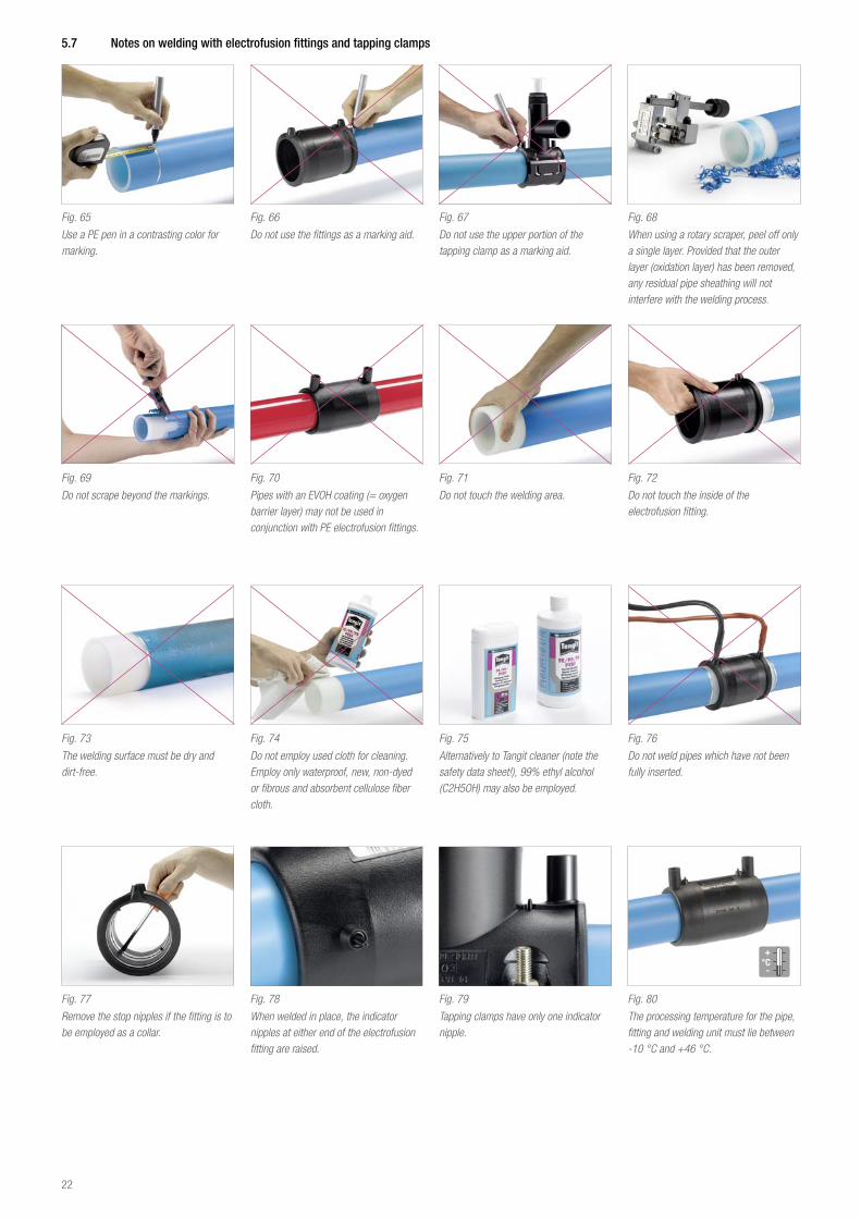
5 7 Notes on welding with electrofusion fittings and tapping clamps
Fig. 65
Use a PE pen in a contrasting color for marking.
Fig. 66
Do not use the fittings as a marking aid.
Fig. 67
Do not use the upper portion of the tapping clamp as a marking aid.
Fig. 68
When using a rotary scraper, peel off only a single layer. Provided that the outer layer (oxidation layer) has been removed, any residual pipe sheathing will not interfere with the welding process.
Fig. 69
Do not scrape beyond the markings.
Fig. 70
Pipes with an EVOH coating (= oxygen barrier layer) may not be used in conjunction with PE electrofusion fittings.
Fig. 71
Do not touch the welding area.
Fig. 72
Do not touch the inside of the electrofusion fitting.
Fig. 73
The welding surface must be dry and dirt-free.
Fig. 74
Do not employ used cloth for cleaning. Employ only waterproof, new, non-dyed or fibrous and absorbent cellulose fiber cloth.
Fig. 75
Alternatively to Tangit cleaner (note the safety data sheet!), 99% ethyl alcohol (C2H5OH) may also be employed.
Fig. 76
Do not weld pipes which have not been fully inserted.
Fig. 77
Remove the stop nipples if the fitting is to be employed as a collar.
Fig. 78
When welded in place, the indicator nipples at either end of the electrofusion fitting are raised.
Fig. 79
Tapping clamps have only one indicator nipple.
Fig. 80
The processing temperature for the pipe, fitting and welding unit must lie between -10 °C and +46 °C.
22
5 8 Branch saddleAlternatively to a tapping clamp, a branch saddle may also be employed. The only difference here is that the pipeline must be pressure-free and empty.
Branch saddle processing instructionsFirst, weld the branch saddle, then create the opening.Use an appropriate tool to create a smooth hole. For more detailed help, please contact either your REHAU Sales Office or REHAU Application Technology.
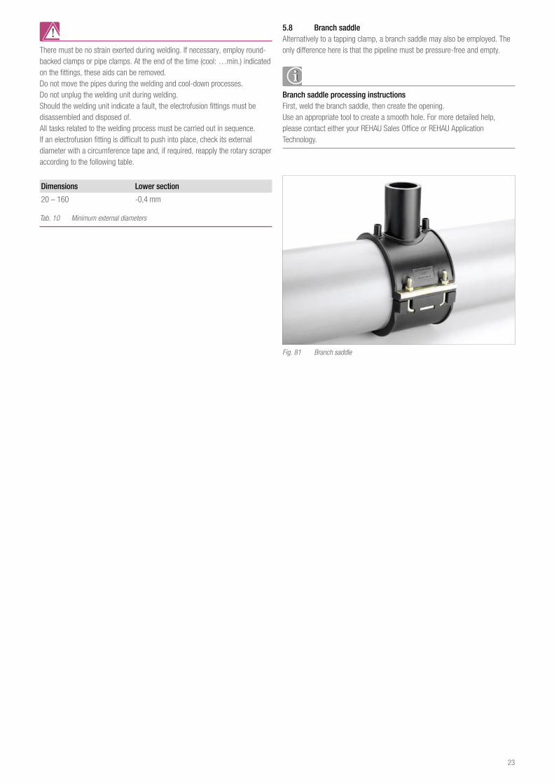
Fig. 81 Branch saddle
There must be no strain exerted during welding. If necessary, employ round-backed clamps or pipe clamps. At the end of the time (cool: …min.) indicated on the fittings, these aids can be removed.Do not move the pipes during the welding and cool-down processes.Do not unplug the welding unit during welding.Should the welding unit indicate a fault, the electrofusion fittings must be disassembled and disposed of.All tasks related to the welding process must be carried out in sequence.If an electrofusion fitting is difficult to push into place, check its external diameter with a circumference tape and, if required, reapply the rotary scraper according to the following table.
Dimensions Lower section
20 – 160 -0,4 mm
Tab. 10 Minimum external diameters
23
6 FuSapex eLeCTrOFuSION FITTINgS MaDe OF pe-x
6 1 Processing requirements
FUSAPEX processing requirementsFUSAPEX electrofusion fittings may only be installed by specialists trained in working with FUSAPEX.The processing company is responsible for ensuring that individuals involved in processing FUSAPEX electrofusion fittings have been properly trained for this task.Training followed by an examination are required in order to properly work with FUSAPEX electrofusion fittings.The processing company is responsible for ensuring that the training is performed by an authorized REHAU trainer, certified for FUSAPEX.Training is restricted to a limited time period, and must be repeated at its conclusion.As proof of training, the participant will receive the FUSAPEX processor card with a personal identification number. The FUSAPEX processor card must be available during every processing stage. Once welding has been successfully completed, the personal identification number and the current date are to be applied to the FUSAPEX electrofusion fitting. The processing company is responsible for ensuring that all processing complies with the most current version of this Technical Information.Work on electrical equipment or pipeline sections may only be performed by properly trained and authorized individuals.
6 2 Program components
6 2 1 FUSAPEX electrofusion fittingThe FUSAPEX electrofusion fitting, made of cross-linked polyethylene (PE-X) is used for the fast, simple and secure connection of PEX pipes, and possesses an operating temperature range between -40 °C and +95 °C.In conjunction with the REHAU industrial pipe and district heating systems, this opens new application areas.Thus, in accordance with our “single source” motto, mixed installations can be frequently avoided.
6 2 1 1 DescriptionFUSAPEX electrofusion fittings are manufactured from cross-linked polyethylene and can be employed together with the following types of PE-Xa pipes:RAUPEX-A;RAUPEX-K;RAUPEX-O;RAUPEX-UV;RAUTHERM-FW;RAUTHERMEX;RAUVITHERM.
FUSAPEX is a registered trademark of REHAU AG + Co.
In conjunction with the indicated pipe types, FUSAPEX electrofusion fittings can be employed for the following applications: - Local and district heating; - Hot and cold water supply; - Nonflammable gases; - Solids transport; - And for numerous industrial media.
100 °C95 °C90 °C
80 °C
70 °C
60 °C
50 °C
40 °C
30 °C
20 °C
10 °C
0 °C
-10 °C
-20 °C
-30 °C
-40 °C
-50 °C
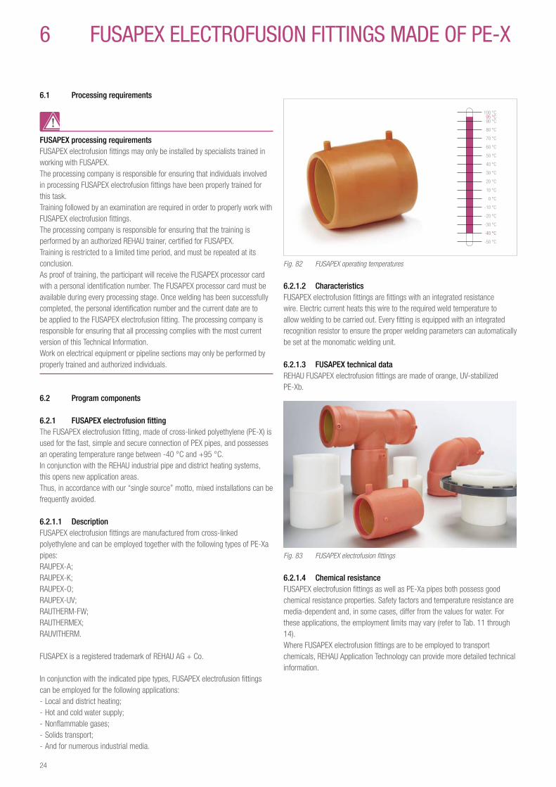
Fig. 82 FUSAPEX operating temperatures
6 2 1 2 CharacteristicsFUSAPEX electrofusion fittings are fittings with an integrated resistance wire. Electric current heats this wire to the required weld temperature to allow welding to be carried out. Every fitting is equipped with an integrated recognition resistor to ensure the proper welding parameters can automatically be set at the monomatic welding unit.
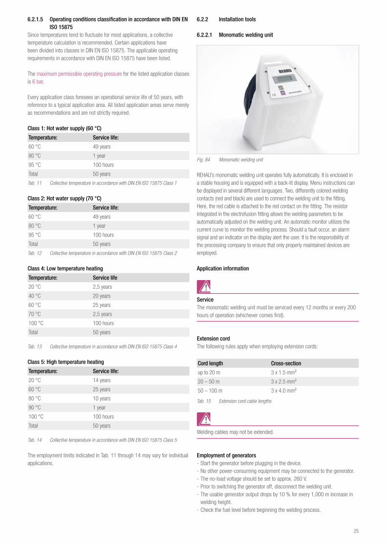
6 2 1 3 FUSAPEX technical dataREHAU FUSAPEX electrofusion fittings are made of orange, UV-stabilized PE-Xb.
Fig. 83 FUSAPEX electrofusion fittings
6 2 1 4 Chemical resistanceFUSAPEX electrofusion fittings as well as PE-Xa pipes both possess good chemical resistance properties. Safety factors and temperature resistance are media-dependent and, in some cases, differ from the values for water. For these applications, the employment limits may vary (refer to Tab. 11 through 14).Where FUSAPEX electrofusion fittings are to be employed to transport chemicals, REHAU Application Technology can provide more detailed technical information.
24
6 2 1 5 Operating conditions classification in accordance with DIN EN ISO 15875
Since temperatures tend to fluctuate for most applications, a collective temperature calculation is recommended. Certain applications have been divided into classes in DIN EN ISO 15875. The applicable operating requirements in accordance with DIN EN ISO 15875 have been listed.
The maximum permissible operating pressure for the listed application classes is 6 bar.
Every application class foresees an operational service life of 50 years, with reference to a typical application area. All listed application areas serve merely as recommendations and are not strictly required.
Class 1: Hot water supply (60 °C)
Temperature: Service life:
60 °C 49 years
80 °C 1 year
95 °C 100 hours
Total 50 years
Tab. 11 Collective temperature in accordance with DIN EN ISO 15875 Class 1
Class 2: Hot water supply (70 °C)
Temperature: Service life:
60 °C 49 years
80 °C 1 year
95 °C 100 hours
Total 50 years
Tab. 12 Collective temperature in accordance with DIN EN ISO 15875 Class 2
Class 4: Low temperature heating
Temperature: Service life
20 °C 2,5 years
40 °C 20 years
60 °C 25 years
70 °C 2,5 years
100 °C 100 hours
Total 50 years
Tab. 13 Collective temperature in accordance with DIN EN ISO 15875 Class 4
Class 5: High temperature heating
Temperature: Service life:
20 °C 14 years
60 °C 25 years
80 °C 10 years
90 °C 1 year
100 °C 100 hours
Total 50 years
Tab. 14 Collective temperature in accordance with DIN EN ISO 15875 Class 5
The employment limits indicated in Tab. 11 through 14 may vary for individual applications.
6 2 2 Installation tools
6 2 2 1 Monomatic welding unit
Fig. 84 Monomatic welding unit
REHAU’s monomatic welding unit operates fully automatically. It is enclosed in a stable housing and is equipped with a back-lit display. Menu instructions can be displayed in several different languages. Two, differently colored welding contacts (red and black) are used to connect the welding unit to the fitting.Here, the red cable is attached to the red contact on the fitting. The resistor integrated in the electrofusion fitting allows the welding parameters to be automatically adjusted on the welding unit. An automatic monitor utilizes the current curve to monitor the welding process. Should a fault occur, an alarm signal and an indicator on the display alert the user. It is the responsibility of the processing company to ensure that only properly maintained devices are employed.
Application information
ServiceThe monomatic welding unit must be serviced every 12 months or every 200 hours of operation (whichever comes first).
Extension cordThe following rules apply when employing extension cords:
Cord length Cross-section
up to 20 m 3 x 1.5 mm²
20 – 50 m 3 x 2.5 mm²
50 – 100 m 3 x 4.0 mm²
Tab. 15 Extension cord cable lengths
Welding cables may not be extended.
Employment of generators - Start the generator before plugging in the device. - No other power-consuming equipment may be connected to the generator. - The no-load voltage should be set to approx. 260 V. - Prior to switching the generator off, disconnect the welding unit. - The usable generator output drops by 10 % for every 1,000 m increase in welding height.
- Check the fuel level before beginning the welding process.
25
To prevent damage to the welding unit, make sure the internal device monitoring functions do not fail. To ensure this, the employed generators must meet the following criteria: - Suitable for phase control operation and inductive loads; - No-load voltage must be able to be set between 245 V - 260 V; - 18 A, single-phase output current; - Stable output current or motor rotation speed, even under rapidly changing loads;
- Synchronous generators with mechanical speed control are preferable; - Voltage peaks must not exceed 800 V.
Nominal generator output: Single phase, 230/240 V, 50/60 Hz
Diameters Output power 20 - 75 mm 2 kW90 - 160 mm 3.2 kW
160 - 355 mm4.5 kW (mechanical control)5 kW (electronic control)
Tab. 16 Nominal generator output
In order to ensure safe operation, the assured output must be 3 – 3.5 times the load for generators with poor control characteristics or for those with limited voltage stabilization. The suitability for employment of generators with electronic controls should be examined in advance, since some of these devices exhibit speed fluctuations, resulting in extreme voltage peaks.
Input voltage (AC) 230 V (185 – 300 V)Input frequency 50 Hz (40 – 70 Hz)Input current level 16 AOutput voltage 40 VMax. output current 60 APower 2600 VA / 80 % EDOperating temperature range -10 °C to +50 °CDevice safety CE, IP 54Weight approx. 18 kgPower cable length 4.5 mWelding cable length 4.7 m
Display2 x 20 characters, back-lit
Dimensions 440 x 380 x 320 mmParameter input AutomaticElectronic monitoring of input voltage / current level / frequency
Electronic monitoring of output voltage, contact, resistance, short-circuit, power output line, welding time, operating temperature, system status
Fault messagesContinuous warning signal, display information
Tab. 17 Technical specifications of the electrofusion fitting welding unit
If the 110 Volt version of the welding unit is employed, the generator used may need to meet a few different requirements. In this case, please contact your local Sales Office.
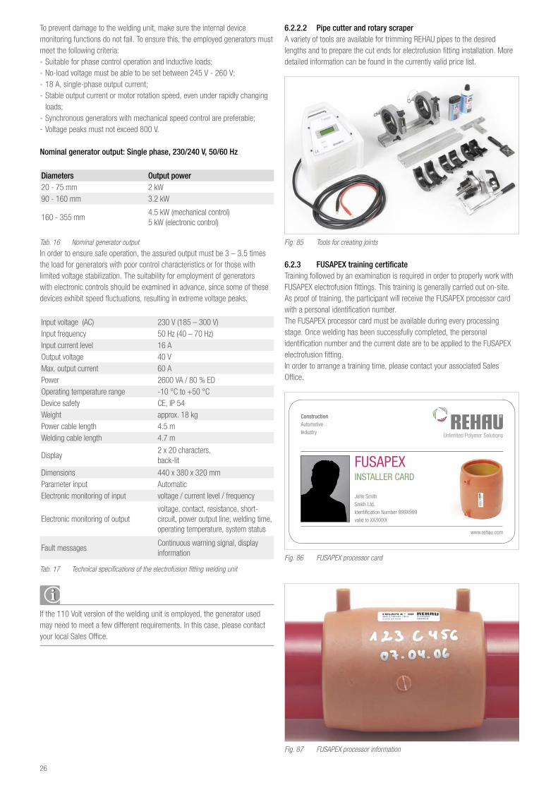
6 2 2 2 Pipe cutter and rotary scraperA variety of tools are available for trimming REHAU pipes to the desired lengths and to prepare the cut ends for electrofusion fitting installation. More detailed information can be found in the currently valid price list.
Fig. 85 Tools for creating joints
6 2 3 FUSAPEX training certificateTraining followed by an examination is required in order to properly work with FUSAPEX electrofusion fittings. This training is generally carried out on-site. As proof of training, the participant will receive the FUSAPEX processor card with a personal identification number.The FUSAPEX processor card must be available during every processing stage. Once welding has been successfully completed, the personal identification number and the current date are to be applied to the FUSAPEX electrofusion fitting.In order to arrange a training time, please contact your associated Sales Office.
FUSAPEX INSTALLER CARD
ConstructionAutomotiveIndustry
www.rehau.com
John SmithSmith Ltd.Identi cation Number 999X999valid to XX/XXXX
DGT00083 EN 10_2006.indd 1 26.10.2006 11:56:15
Fig. 86 FUSAPEX processor card
Fig. 87 FUSAPEX processor information
26
6 3 3 Preparing pipe ends
6 3 FUSAPEX electrofusion fitting jointsIn order to create FUSAPEX electrofusion fitting joints, you must be both trained and possess a valid FUSAPEX processor card. Please always keep this card on hand.Please note the safety information in Chapter 1 and Section 6.1.
6 3 1 Tool preparationPrepare the tools required for installation (refer to the current price list) at the work location, and examine them for proper function.
6 3 2 Pipe and fitting inspection
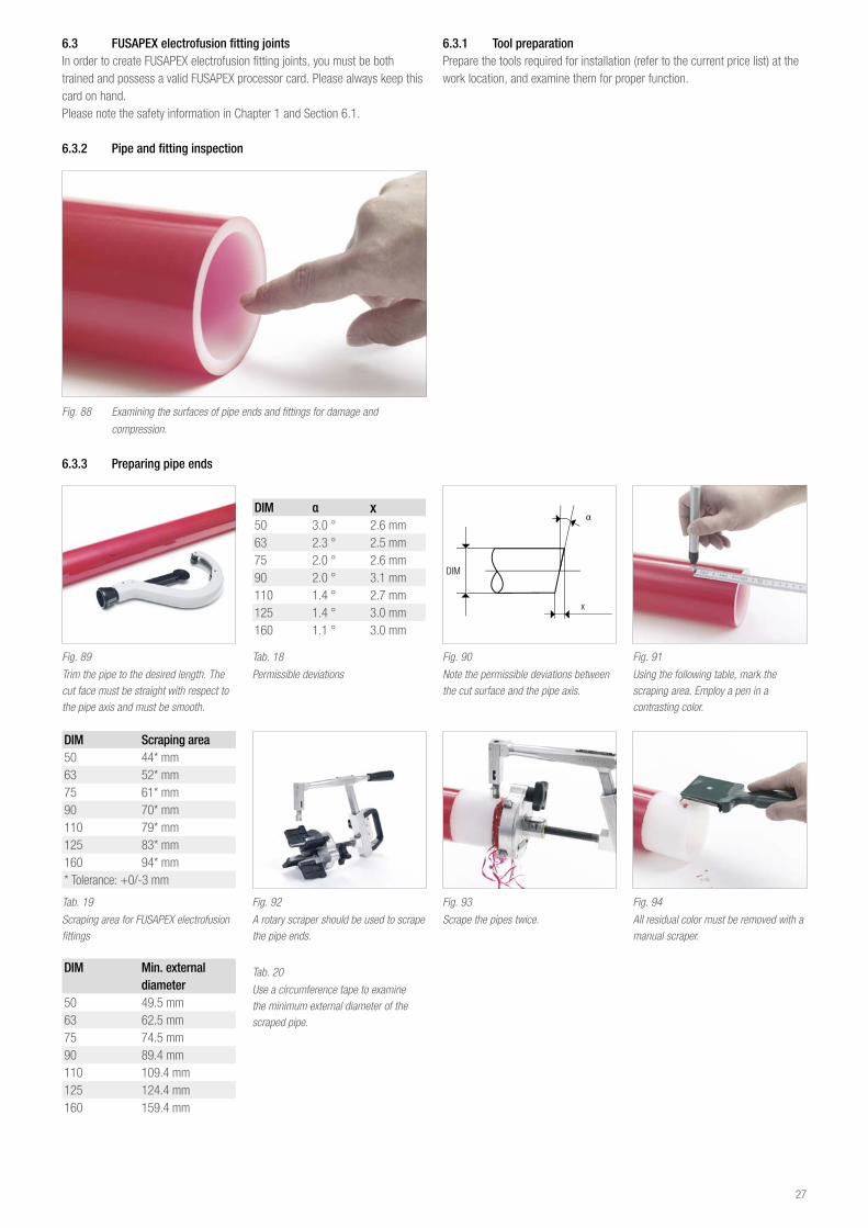
Fig. 88 Examining the surfaces of pipe ends and fittings for damage and
compression.
Fig. 89
Trim the pipe to the desired length. The cut face must be straight with respect to the pipe axis and must be smooth.
DIM α x50 3.0 ° 2.6 mm63 2.3 ° 2.5 mm75 2.0 ° 2.6 mm90 2.0 ° 3.1 mm110 1.4 ° 2.7 mm125 1.4 ° 3.0 mm160 1.1 ° 3.0 mm
Tab. 18
Permissible deviations
Fig. 90
Note the permissible deviations between the cut surface and the pipe axis.
Fig. 91
Using the following table, mark the scraping area. Employ a pen in a contrasting color.
DIM Scraping area50 44* mm63 52* mm75 61* mm90 70* mm110 79* mm125 83* mm160 94* mm* Tolerance: +0/-3 mm
Tab. 19
Scraping area for FUSAPEX electrofusion fittings
Fig. 92
A rotary scraper should be used to scrape the pipe ends.
Fig. 93
Scrape the pipes twice.
Fig. 94
All residual color must be removed with a manual scraper.
DIM Min external diameter
50 49.5 mm63 62.5 mm75 74.5 mm90 89.4 mm110 109.4 mm125 124.4 mm160 159.4 mm
Tab. 20
Use a circumference tape to examine the minimum external diameter of the scraped pipe.
27
6 3 4 Connecting pipe ends using FUSAPEX
Fig. 95
The scraping area must be free of dirt and oil. Clean the area with an adequate amount of Tangit cleaner, and subsequently allow the cleaning agent to completely evaporate.
Fig. 96
Now remove the FUSAPEX electrofusion fitting from its bag. If necessary, clean the fitting with Tangit cleaner.
Fig. 97
Push the FUSAPEX electrofusion fitting completely onto the first pipe end.
Fig. 98
Mount the universal pipe clamps as close as possible to the FUSAPEX electrofusion fitting.
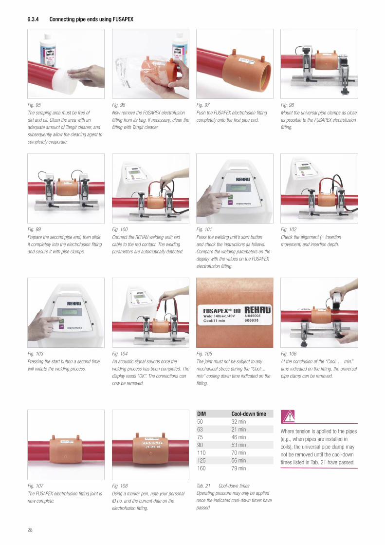
Fig. 99
Prepare the second pipe end, then slide it completely into the electrofusion fitting and secure it with pipe clamps.
Fig. 100
Connect the REHAU welding unit; red cable to the red contact. The welding parameters are automatically detected.
Fig. 101
Press the welding unit’s start button and check the instructions as follows. Compare the welding parameters on the display with the values on the FUSAPEX electrofusion fitting.
Fig. 102
Check the alignment (= insertion movement) and insertion depth.
Fig. 103
Pressing the start button a second time will initiate the welding process.
Fig. 104
An acoustic signal sounds once the welding process has been completed. The display reads “OK”. The connections can now be removed.
Fig. 105
The joint must not be subject to any mechanical stress during the “Cool:...min” cooling down time indicated on the fitting.
Fig. 106
At the conclusion of the “Cool: … min.” time indicated on the fitting, the universal pipe clamp can be removed.
Fig. 107
The FUSAPEX electrofusion fitting joint is now complete.
Fig. 108
Using a marker pen, note your personal ID no. and the current date on the electrofusion fitting.
DIM Cool-down time50 32 min63 21 min75 46 min90 53 min110 70 min125 56 min160 79 min
Tab. 21 Cool-down times Operating pressure may only be applied once the indicated cool-down times have passed.
Where tension is applied to the pipes (e.g., when pipes are installed in coils), the universal pipe clamp may not be removed until the cool-down times listed in Tab. 21 have passed.
28
6 3 5 Notes on welding with FUSAPEX electrofusion fittings
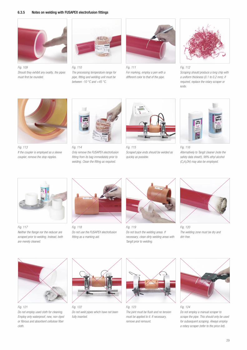
Fig. 109
Should they exhibit any ovality, the pipes must first be rounded.
Fig. 110
The processing temperature range for pipe, fitting and welding unit must be between -10 °C and +45 °C.
Fig. 111
For marking, employ a pen with a different color to that of the pipe.
Fig. 112
Scraping should produce a long chip with a uniform thickness (0.1 to 0.2 mm); if required, replace the rotary scraper or knife.
Fig. 113
If the coupler is employed as a sleeve coupler, remove the stop nipples.
Fig. 114
Only remove the FUSAPEX electrofusion fitting from its bag immediately prior to welding. Clean the fitting as required.
Fig. 115
Scraped pipe ends should be welded as quickly as possible.
Fig. 116
Alternatively to Tangit cleaner (note the safety data sheet!), 99% ethyl alcohol (C2H5OH) may also be employed.
Fig. 117
Neither the flange nor the reducer are scraped prior to welding. Instead, both are merely cleaned.
Fig. 118
Do not use the FUSAPEX electrofusion fitting as a marking aid.
Fig. 119
Do not touch the welding areas. If necessary, clean dirty welding areas with Tangit prior to welding.
Fig. 120
The welding zone must be dry and dirt-free.
Fig. 121
Do not employ used cloth for cleaning. Employ only waterproof, new, non-dyed or fibrous and absorbent cellulose fiber cloth.
Fig. 122
Do not weld pipes which have not been fully inserted.
Fig. 123
The joint must be flush and no tension must be applied to it. If necessary, remove and remount.
Fig. 124
Do not employ a manual scraper to scrape the pipe. This should only be used for subsequent scraping. Always employ a rotary scraper (refer to the price list).
29
- There must be no strain exerted during welding, therefore round-backed clamps or pipe clamps must be used.
- Do not move the pipes during welding. - Do not unplug the welding unit during welding. - Should the welding unit indicate a fault, should the power supply be interrupted during welding, or if the welding process is manually interrupted, the joint must be cut out and replaced. The FUSAPEX electrofusion fitting may not be reused.
- If mechanical strain is applied to the FUSAPEX electrofusion fitting during welding or during the indicated cool-down period “cool ... min”, the joint must be cut out and replaced. The FUSAPEX electrofusion fitting may not be reused.
- Approval on the part of REHAU Application Technology is required if REHAU pipes and FUSAPEX electrofusion fittings come into contact with aggressive media.
- We recommend performing a pressure check as described in Chapter 16 at the conclusion of the installation.
6 4 Shipping and storageREHAU pipes, FUSAPEX electrofusion fittings as well as all other system components must be loaded and unloaded under expert supervision. Unprotected pipes or fittings must not be stored on the ground or be dragged across concrete surfaces. They are to be stored on a level surface with no sharp edges or corners. Light-impermeable plastic sheeting is to be employed to cover and protect pipes and fittings against oils, grease, colors, etc.Unprotected outdoor storage is prohibited. We recommend removing the packaging from the pipes only immediately prior to processing.
FUSAPEX electrofusion fittingsFUSAPEX fittings should remain in their PE bags until immediately prior to the joint being created.To store the FUSAPEX fittings, place their PE bags in a light-impenetrable container (e.g., box) in a closed, dry room at an ambient temperature of approx. 20 °C.
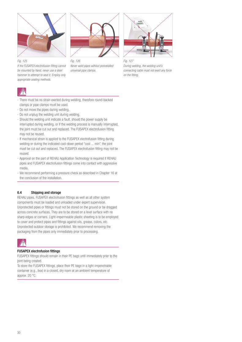
Fig. 125
If the FUSAPEX electrofusion fitting cannot be mounted by hand, never use a steel hammer to attempt to seat it. Employ only appropriate seating methods.
Fig. 126
Never weld pipes without preinstalled universal pipe clamps.
Fig. 127
During welding, the welding unit’s connecting cable must not exert any force on the fitting.
30
7 preSSure equIpMeNT DIreCTIVe 97/23/eC
As of 1997/05/29, the Pressure Equipment Directive, 97/23/EC, is the sole regulation which has applied to trade in pressure equipment within the European Union. The function of this directive is regulatory and compliance is mandatory throughout the European Union. As of this date, alternate national regulations governing dealings with pressure equipment are no longer applicable. Within the context of the directive, pressure equipment is considered to comprise containers, pipelines, accessory fittings with a safety function, or assemblies intended to retain pressure up to a maximum pressure of > 0.5 bar. As pipelines also fall under the requirements of this pressure equipment directive, the manufacturer of the pipeline must apply a CE label and prepare a conformity declaration (refer to the following legal information).
Within the context of the pressure equipment directive, a pipeline manufacturer is the installer, the fabricator or the assembly manufacturer who creates pipelines from individual components (such as pipes, fittings, compression sleeves). The pressure equipment directive refers to these individual components as “materials”. Therefore, within the context of the pressure equipment directive, the components comprising the RAUPEX industrial piping systems, such as pipes, fittings, compression sleeves as well as accessories are classed as “materials”. Exceptions to this classification include ball valves, compressed air junction boxes and quick-release safety couplings.
If, in his role as a “manufacturer of pipelines”, the manufacturer must prepare a conformity declaration and apply a CE label to the equipment, he must be able to provide evidence that all components and materials comply with the system threshold values for the pipeline.In concrete terms, this means that documentation related to the operating limits for the utilized components may need to be on file, and that plant certificates 2.2 or acceptance test certificates 3.1 in accordance with DIN EN 10204 may need to be made available.
To obtain a plant certificate 2.2 in accordance with DIN EN 10204 or an acceptance test certificate 3.1 in accordance with DIN EN 10204, please contact your REHAU representatives.
You can find the associated text for the pressure equipment directive on the official pages of the European Union.
31
8 COMpreSSeD aIr TeCHNOLOgY
8 1 General informationCompressed air is employed throughout the entire industry, from small workshops through to the largest manufacturing operations. Whether it is used to drive tools and machinery or for components, for controlling or cleaning, modern manufacturing operations can no longer be imagined without compressed air.
8 2 Compressed air energy costsOne large disadvantage of compressed air is the high energy cost. In this regard, leaks in the pipeline system play a not inconsiderable role. The causes for the energy loss can frequently be found in threaded connections which are no longer air-tight, dried seals in the threaded connections, holes resulting from corrosion, seals destroyed by compressor oil, faulty adhesions, etc. For these reasons, it is vital to consider pressure tightness when selecting a pipeline system. The RAUPEX industrial piping systems has been manufactured so that it complies with the pressure equipment directive with respect to the pipeline material and the employed jointing technology. Thanks to its pressure tightness, RAUPEX represents the ideal solution to reduce energy cost.
Hole Ø[mm]
Air loss at 6 bar [l/s]
Energy loss [kWh/h]
Costs*[€/a]
1 1.238 0.3 390,-
3 11.14 3.1 4.070,-
5 30.95 8.3 10.890,-
10123.8 33.0 43.310,-
* Cost determination: kW x 0.15 €/kWh x 8750 operating hours/a
Tab. 22 Costs for leaks from various hole sizes
8 3 Advantages of the RAUPEX industrial piping systems for compressed air technology
Thanks to its combination of RAUPEX pipes and the jointing technologies employing compression sleeves and electrofusion fittings, the RAUPEX industrial piping systems represents an outstanding solution for the application as a compressed air pipeline. This results in numerous advantages for the user:
- No pipeline leaks, no energy losses and lower operating costs; - No corrosion, resulting in a longer pipeline system service life and lower investment costs;
- Uniform compressed air quality, no contamination by corrosion products, reduced number of additional filters;
- Pipe in accordance with standardized colors, no need for additional painting; - Quick installation techniques, reduced installation expenses, on-time scheduling;
- Easily learned installation techniques; - Light-weight raw materials, simple overhead installation and expenses for hangers much less than for standard steel pipe;
- Can be employed as either flexible or rigid pipelines; - Underground or interior building installation possible; - Pipe available in sections or on rolls; - Expansion during operation possible (tapping clamp); - Suitable for renovations and new constructions; - Good resistance to compressor oils; - Economical total installation.
8 4 Compressed air qualityVarious compressed air applications require different compressed air quality. For compressed air applications, uniform quality at every draw off point is vital. Therefore, the compressed air quality must not be compromised by the pipe material. The RAUPEX industrial piping systems ensures uniform air quality throughout the entire network, from generation and preparation, through to the end user.In accordance with ISO 8573/VDMA 15390, compressed air quality is defined according to the following three factors: solids content, water content and oil content.Since specific applications make different demands on each of these three factors, they are classified.
8 4 1 Quality classes for maximum particle sizes and maximum particle numbers
Contamination in the air results in solid particles occurring in the compressed air. Depending on the specific requirements, filters can reduce the size and number of these particles.
Solid Particle contamination
Class≤ 0.1μm
> 0.1 –≤ 0.5 μm
>0.5 –≤ 1.0 μm
> 1.0 –≤ 5.0 μm
0 better than Class 1, and subject to a separate agreement
1 n. V. 100 1 0
2 - 100000 1000 10
3 - - 10000 500
4 - - - 1000
5 - - - 20000
Maximum number of particles of the defined sizes per m³, in mm, measured in accordance with ISO 8573-4
Reference conditions: 1 bar absolute, 20 °C, 0% relative humidity
Tab. 23 Quality classes for solids in accordance with ISO 8573-1 / VDMA 15390
32
8 4 2 Water content quality classesCompressing ambient air greatly increases the moisture of compressed air. Typically the air is de-humidified in the air treatment unit to prevent condensation as much as possible within the pipe network. The pressure dew point has proven itself as a reliable method for measuring and classifying the amount of water in compressed air.The pressure dew point defines the temperature at which the water in the compressed air begins to condense. The following table also includes the residual moisture, in g/m³.
Moisture (vapor)
Class Pressure dew point Residual moisture
0 better than Class 1, and subject to a separate agreement
1 ≤ -70°C ≤ 0.003 g/m³
2 ≤ -40°C ≤ 0.11 g/m³
3 ≤ -20°C ≤ 0.88 g/m³
4 ≤ +3°C ≤ 6.0 g/m³
5 ≤ +7°C ≤ 7.8 g/m³
6 ≤ +10°C ≤ 9.4 g/m³
Maximum pressure dew point, measured in accordance with ISO 8573-3
Reference conditions: 7 bar operating pressure, 20 °C
Tab. 24 24 Quality classes for water content and pressure dew point, in accordance with ISO 8573-1 / VDMA 15390
8 4 3 Oil content quality classes
Class Total oil content (liquid and gaseous)
0 better than Class 1, and subject to a separate agreement
1 ≤ 0.01 mg/m³
2 ≤ 0.1 mg/m³
3 ≤ 1 mg/m³
4 ≤ 5 mg/m³
Maximum oil content, measured in accordance with ISO 8573-2 and ISO 8573-5
Reference conditions: 1 bar absolute, 20 °C, 0% relative humidity.
Tab. 25 Quality classes for oil content, in accordance with ISO 8573-1 / VDMA 15390
Applications Quality classes
Solid particles Moisture (as vapor) Total oil content Sterile
Ambient temperature >3 °C
Ambient temperature ≤3 °C
A B1 B2 C D
34 Chemical industry, chemical fiber manufacturing
35 Pneumatics 2 4 2-3 2
36 Air propelled system 2 4 2-3 1
50 Metal manufacturing and processing
52 Cleaning of tool moulds 3 4 2-3 3
62 Machinery and equipment manufacturing
64 Air blowing 2-3 4 2-3 2
66 Process air 2 4 2-3 1
67 Electro-technology, electronics
69 Chip manufacturing – air blowing, instrument air 0-1 1-2 - 1
71 CD manufacturing 1-2 4 - 1
Tab. 26 Extract from the list of recommended purity classes in accordance with VDMA 15390
8 4 4 Examples of compressed air quality classesVDMA 15390 lists a number of purity classes, broken down by industry branches. The following table provides several examples of these recommendations.
33
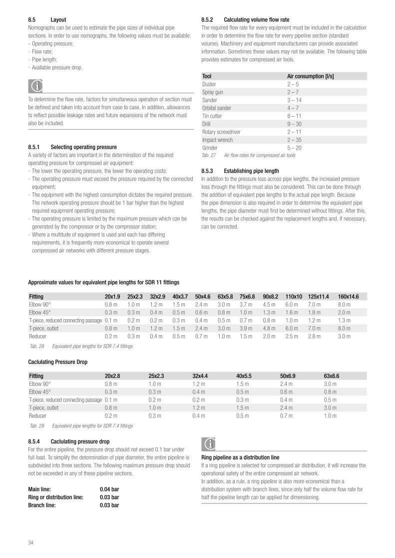
8 5 LayoutNomographs can be used to estimate the pipe sizes of individual pipe sections. In order to use nomographs, the following values must be available: - Operating pressure; - Flow rate; - Pipe length; - Available pressure drop.
To determine the flow rate, factors for simultaneous operation of section must be defined and taken into account from case to case. In addition, allowances to reflect possible leakage rates and future expansions of the network must also be included.
8 5 1 Selecting operating pressureA variety of factors are important in the determination of the required operating pressure for compressed air equipment: - The lower the operating pressure, the lower the operating costs; - The operating pressure must exceed the pressure required by the connected equipment;
- The equipment with the highest consumption dictates the required pressure. The network operating pressure should be 1 bar higher than the highest required equipment operating pressure;
- The operating pressure is limited by the maximum pressure which can be generated by the compressor or by the compressor station;
- Where a multitude of equipment is used and each has differing requirements, it is frequently more economical to operate several compressed air networks with different pressure stages.
8 5 2 Calculating volume flow rate The required flow rate for every equipment must be included in the calculation in order to determine the flow rate for every pipeline section (standard volume). Machinery and equipment manufacturers can provide associated information. Sometimes these values may not be available. The following table provides estimates for compressed air tools.
Tool Air consumption [l/s]Duster 2 – 5 Spray gun 2 – 7 Sander 3 – 14 Orbital sander 4 – 7 Tin cutter 8 – 11Drill 9 – 30Rotary screwdriver 2 – 11Impact wrench 2 – 35Grinder 5 – 20 Tab. 27 Air flow rates for compressed air tools
8 5 3 Establishing pipe lengthIn addition to the pressure loss across pipe lengths, the increased pressure loss through the fittings must also be considered. This can be done through the addition of equivalent pipe lengths to the actual pipe length. Because the pipe dimension is also required in order to determine the equivalent pipe lengths, the pipe diameter must first be determined without fittings. After this, the results can be checked against the replacement lengths and, if necessary, can be corrected.
Approximate values for equivalent pipe lengths for SDR 11 fittings
Fitting 20x1 9 25x2 3 32x2 9 40x3 7 50x4 6 63x5 8 75x6 8 90x8 2 110x10 125x11 4 160x14 6Elbow 90° 0.8 m 1.0 m 1.2 m 1.5 m 2.4 m 3.0 m 3.7 m 4.5 m 6.0 m 7.0 m 8.0 mElbow 45° 0.3 m 0.3 m 0.4 m 0.5 m 0.6 m 0.8 m 1.0 m 1.3 m 1.6 m 1.8 m 2.0 mT-piece, reduced connecting passage 0.1 m 0.2 m 0.2 m 0.3 m 0.4 m 0.5 m 0.7 m 0.8 m 1.0 m 1.2 m 1.3 mT-piece, outlet 0.8 m 1.0 m 1.2 m 1.5 m 2.4 m 3.0 m 3.9 m 4.8 m 6.0 m 7.0 m 8.0 mReducer 0.2 m 0.3 m 0.4 m 0.5 m 0.7 m 1.0 m 1.5 m 2.0 m 2.5 m 2.8 m 3.0 m
Tab. 28 Equivalent pipe lengths for SDR 7.4 fittings
Caclulating Pressure Drop
Fitting 20x2 8 25x2 3 32x4 4 40x5 5 50x6 9 63x8 6Elbow 90° 0.8 m 1.0 m 1.2 m 1.5 m 2.4 m 3.0 mElbow 45° 0.3 m 0.3 m 0.4 m 0.5 m 0.6 m 0.8 mT-piece, reduced connecting passage 0.1 m 0.2 m 0.2 m 0.3 m 0.4 m 0.5 mT-piece, outlet 0.8 m 1.0 m 1.2 m 1.5 m 2.4 m 3.0 mReducer 0.2 m 0.3 m 0.4 m 0.5 m 0.7 m 1.0 m
Tab. 29 Equivalent pipe lengths for SDR 7.4 fittings
8 5 4 Caclulating pressure dropFor the entire pipeline, the pressure drop should not exceed 0.1 bar under full load. To simplify the determination of pipe diameter, the entire pipeline is subdivided into three sections. The following maximum pressure drop should not be exceeded in any of these pipeline sections.
Main line: 0 04 barRing or distribution line: 0 03 barBranch line: 0 03 bar
Ring pipeline as a distribution lineIf a ring pipeline is selected for compressed air distribution, it will increase the operational safety of the entire compressed air network.In addition, as a rule, a ring pipeline is also more economical than a distribution system with branch lines, since only half the volume flow rate for half the pipeline length can be applied for dimensioning.
34
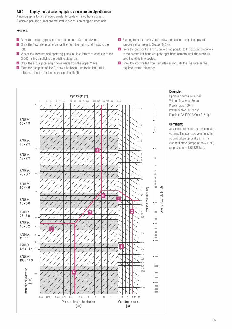
8 5 5 Employment of a nomograph to determine the pipe diameterA nomograph allows the pipe diameter to be determined from a graph.A colored pen and a ruler are required to assist in creating a nomograph.
Process:
1 Draw the operating pressure as a line from the X axis upwards.2 Draw the flow rate as a horizontal line from the right-hand Y axis to the
left.3 Where the flow rate and operating pressure lines intersect, continue to the
2,000 m line parallel to the existing diagonals.4 Draw the actual pipe length downwards from the upper X axis.5 From the end point of line 3, draw a horizontal line to the left until it
intersects the line for the actual pipe length (4).
Example:Operating pressure: 8 barVolume flow rate: 50 l/sPipe length: 400 mPressure drop: 0.03 barEquals a RAUPEX-A 90 x 8.2 pipe
Comment:All values are based on the standard volume. The standard volume is the volume taken up by dry air in its standard state (temperature = 0 °C, air pressure = 1.01325 bar).
6 Starting from the lower X axis, draw the pressure drop line upwards (pressure drop, refer to Section 8.5.4).
7 From the end point of line 5, draw a line parallel to the existing diagonals to the bottom left-hand or upper right-hand corners, until the pressure drop line (6) is intersected.
8 Draw towards the left from this intersection until the line crosses the required internal diameter.
Pipe length [m]
Volu
me
flow
rate
[l/s
]
Volu
me
flow
rate
[m³/
h]
Pressure loss in the pipeline [bar]
Inte
rnal
pip
e di
amet
er [m
m]
Operating pressure [bar]
4
53
27
8
1
6
35
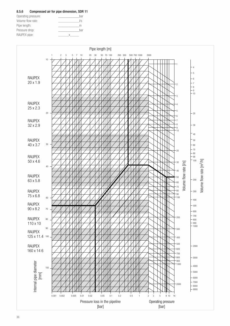
8 5 6 Compressed air for pipe dimension, SDR 11Operating pressure: ____________barVolume flow rate: ____________l/sPipe length: ____________mPressure drop: ____________barRAUPEX pipe: ______x_____
Pipe length [m]
Inte
rnal
pip
e di
amet
er [m
m]
Pressure loss in the pipeline [bar]
Operating pressure [bar]
Volu
me
flow
rate
[l/s
]
Volu
me
flow
rate
[m³/
h]
36
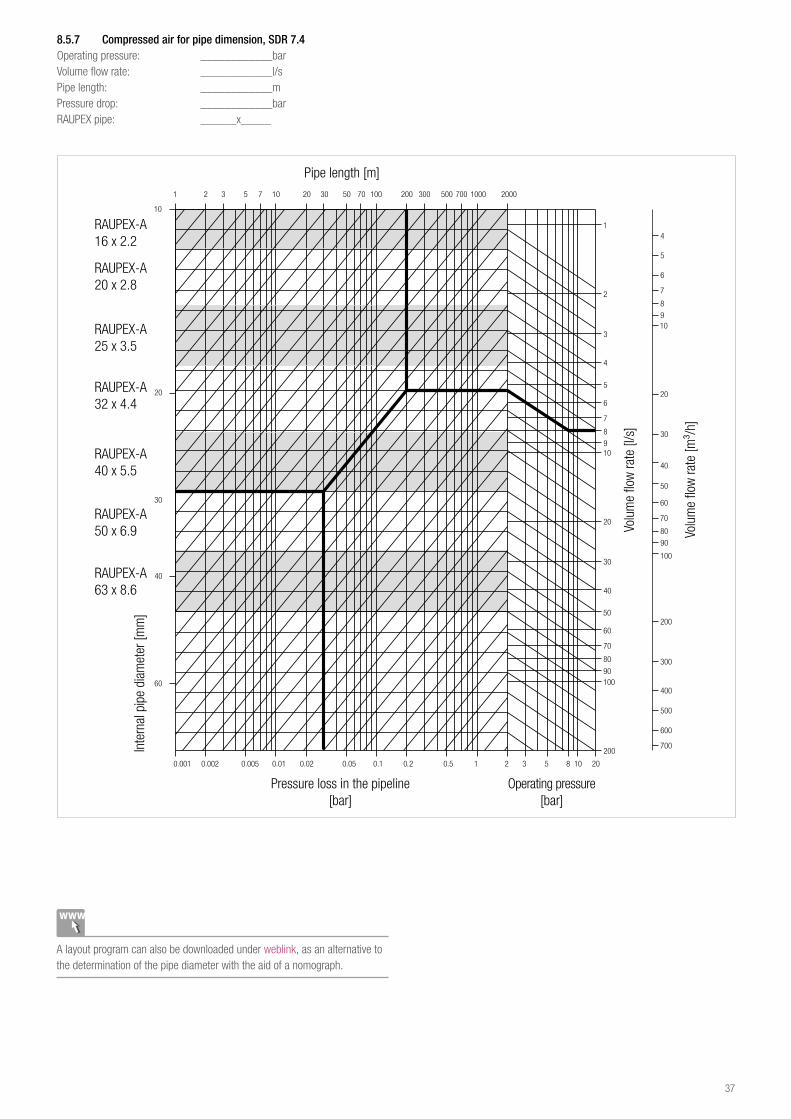
8 5 7 Compressed air for pipe dimension, SDR 7 4Operating pressure: ____________barVolume flow rate: ____________l/sPipe length: ____________mPressure drop: ____________barRAUPEX pipe: ______x_____
Pipe length [m]
Inte
rnal
pip
e di
amet
er [m
m]
Pressure loss in the pipeline [bar]
Operating pressure [bar]
Volu
me
flow
rate
[l/s
]
Volu
me
flow
rate
[m³/
h]
RAUPEX-A16 x 2.2
RAUPEX-A20 x 2.8
RAUPEX-A25 x 3.5
RAUPEX-A32 x 4.4
RAUPEX-A40 x 5.5
RAUPEX-A50 x 6.9
RAUPEX-A63 x 8.6
A layout program can also be downloaded under weblink, as an alternative to the determination of the pipe diameter with the aid of a nomograph.
37
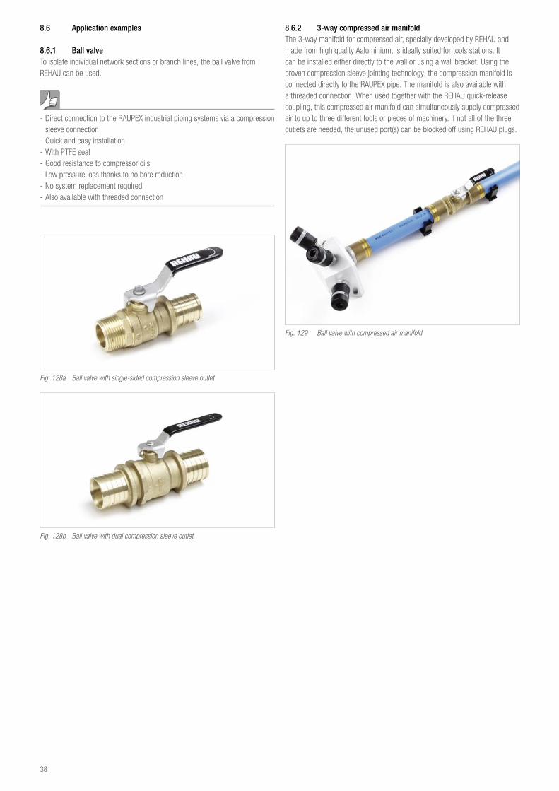
8 6 Application examples
8 6 1 Ball valveTo isolate individual network sections or branch lines, the ball valve from REHAU can be used.
- Direct connection to the RAUPEX industrial piping systems via a compression sleeve connection
- Quick and easy installation - With PTFE seal - Good resistance to compressor oils - Low pressure loss thanks to no bore reduction - No system replacement required - Also available with threaded connection
Fig. 128a Ball valve with single-sided compression sleeve outlet
Fig. 128b Ball valve with dual compression sleeve outlet
8 6 2 3-way compressed air manifoldThe 3-way manifold for compressed air, specially developed by REHAU and made from high quality Aaluminium, is ideally suited for tools stations. It can be installed either directly to the wall or using a wall bracket. Using the proven compression sleeve jointing technology, the compression manifold is connected directly to the RAUPEX pipe. The manifold is also available with a threaded connection. When used together with the REHAU quick-release coupling, this compressed air manifold can simultaneously supply compressed air to up to three different tools or pieces of machinery. If not all of the three outlets are needed, the unused port(s) can be blocked off using REHAU plugs.
Fig. 129 Ball valve with compressed air manifold
38
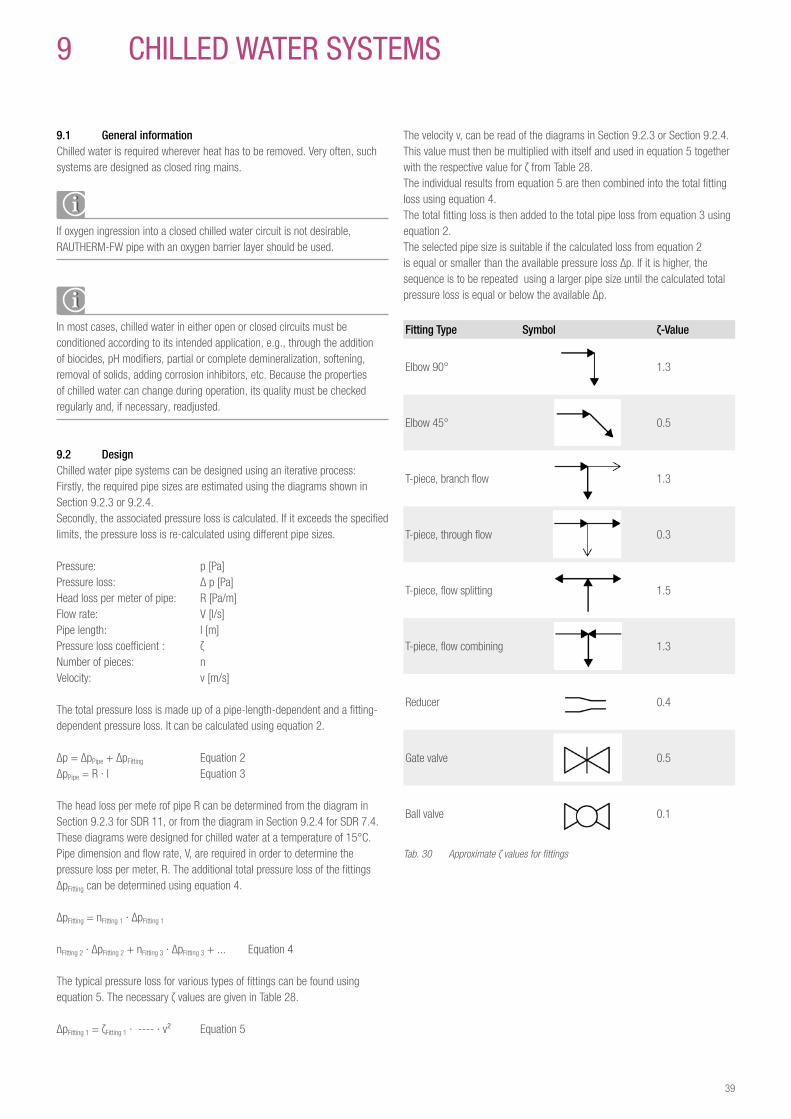
The velocity v, can be read of the diagrams in Section 9.2.3 or Section 9.2.4. This value must then be multiplied with itself and used in equation 5 together with the respective value for ζ from Table 28.The individual results from equation 5 are then combined into the total fitting loss using equation 4. The total fitting loss is then added to the total pipe loss from equation 3 using equation 2.The selected pipe size is suitable if the calculated loss from equation 2 is equal or smaller than the available pressure loss Δp. If it is higher, the sequence is to be repeated using a larger pipe size until the calculated total pressure loss is equal or below the available Δp.
Fitting Type Symbol ζ-Value
Elbow 90° 1.3
Elbow 45° 0.5
T-piece, branch flow 1.3
T-piece, through flow 0.3
T-piece, flow splitting 1.5
T-piece, flow combining 1.3
Reducer 0.4
Gate valve 0.5
Ball valve 0.1
Tab. 30 Approximate ζ values for fittings
9 CHILLeD waTer SYSTeMS
9 1 General informationChilled water is required wherever heat has to be removed. Very often, such systems are designed as closed ring mains.
If oxygen ingression into a closed chilled water circuit is not desirable, RAUTHERM-FW pipe with an oxygen barrier layer should be used.
In most cases, chilled water in either open or closed circuits must be conditioned according to its intended application, e.g., through the addition of biocides, pH modifiers, partial or complete demineralization, softening, removal of solids, adding corrosion inhibitors, etc. Because the properties of chilled water can change during operation, its quality must be checked regularly and, if necessary, readjusted.
9 2 DesignChilled water pipe systems can be designed using an iterative process:Firstly, the required pipe sizes are estimated using the diagrams shown in Section 9.2.3 or 9.2.4. Secondly, the associated pressure loss is calculated. If it exceeds the specified limits, the pressure loss is re-calculated using different pipe sizes.
Pressure: p [Pa]Pressure loss: Δ p [Pa]Head loss per meter of pipe: R [Pa/m]Flow rate: V [l/s]Pipe length: l [m]Pressure loss coefficient : ζNumber of pieces: nVelocity: v [m/s]
The total pressure loss is made up of a pipe-length-dependent and a fitting-dependent pressure loss. It can be calculated using equation 2.
Δp = ΔpPipe + ΔpFitting Equation 2ΔpPipe = R · I Equation 3
The head loss per mete rof pipe R can be determined from the diagram in Section 9.2.3 for SDR 11, or from the diagram in Section 9.2.4 for SDR 7.4. These diagrams were designed for chilled water at a temperature of 15°C.Pipe dimension and flow rate, V, are required in order to determine the pressure loss per meter, R. The additional total pressure loss of the fittings ΔpFitting can be determined using equation 4.
ΔpFitting = nFitting 1 · ΔpFitting 1
nFitting 2 · ΔpFitting 2 + nFitting 3 · ΔpFitting 3 + ... Equation 4
The typical pressure loss for various types of fittings can be found using equation 5. The necessary ζ values are given in Table 28.
ΔpFitting 1 = ζFitting 1 · ---- · v² Equation 5
39
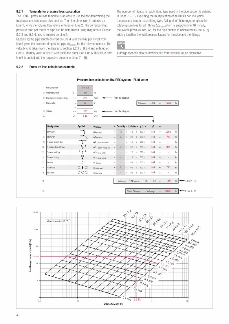
9 2 1 Template for pressure loss calculationThe REHAU pressure loss template is an easy to use tool for determining the total pressure loss in one pipe section. The pipe dimension is entered on Line 1, while the volume flow rate is entered on Line 2. The corresponding pressure drop per meter of pipe can be determined using diagrams in Section 9.2.3 and 9.2.4, and is entered on Line 3.Multiplying the pipe length entered on Line 4 with the loss per meter from line 3 gives the pressure drop in the pipe Δppipeline for the relevant section. The velocity v, is taken from the diagrams Section 9.2.3 or 9.2.4 and entered on Line 5. Multiply value of line 5 with itself and enter it on Line 6.This value from line 6 is copied into the respective column in Lines 7 - 15.
The number of fittings for each fitting type used in the pipe section is entered in Lines 7 – 15. Executing the multiplication of all values per line yields the pressure loss for each fitting type. Ading all of them together gives the totalpressure loss for all fittings Δpfittings.which is enterd in line 16. Finally, the overall pressure loss, Δp, for the pipe section is calculated in Line 17 by adding together the totalpressure losses for the pipe and the fittings .
A design tool can also be downloaded from weblink, as an alternative.
9 2 2 Pressure loss calculation example
1 Pipe dimension:
2 Volume flow rate: V = l/s
3 Pipe abrasion pressure drop: R = Pa/m
4 Pipe length: l = m = Pa
=
5 Velocity: v = m/s
6 v²= m²/s²
Designation ∆pFittings = Quantity x ζ -Value x ρ/2 x v² =
7 Elbow 90° ∆p Elbow 90° = x 1.3 x 500 x = Pa
8 Elbow 45° ∆p Elbow 45° = x 0.5 x 500 x = Pa
9 T-piece, branch flow ∆p T-piece, branch flow = x 1.3 x 500 x = Pa
10 T-section, through flow ∆p T-section, through flow = x 0.3 x 500 x = Pa
11 T-piece, splitting ∆p T-piece, splitting = x 1.5 x 500 x = Pa
12 T-piece, uniting ∆p T-piece, uniting = x 1.3 x 500 x = Pa
13 Reducer ∆p Reducer = x 0.4 x 500 x = Pa
14 Gate valve ∆p Gate valve = x 0.5 x 500 x = Pa
15 Ball valve ∆p Ball valve = x 0.1 x 500 x = Pa
16 = Pa
17 = Pa
Symbol
Pressure loss calculation RAUPEX system - Fluid water
Σ Line 4 + 16
from the diagram
Σ Line 7 - 15
from the diagram
∆p Pipeline = R x l
∆p Fittings = ∆p elbow 90° + ∆p ..... + ∆p .....
∆p = ∆p Pipeline + ∆p Fittings
75 x 6.8
3.6
250
60
1.2
1.44
10
2
-
4
-
-
-
2
-
1.44
1.44
1.44
1.44
1.44
1.44
1.44
1.44
1.44
9360
720
-
864
-
-
-
720
-
15000
11664
26664
Head
loss
per
met
er o
f pip
e R
[Pa/
m]
Volume flow rate [l/s]
Water temperature 15 °C
40
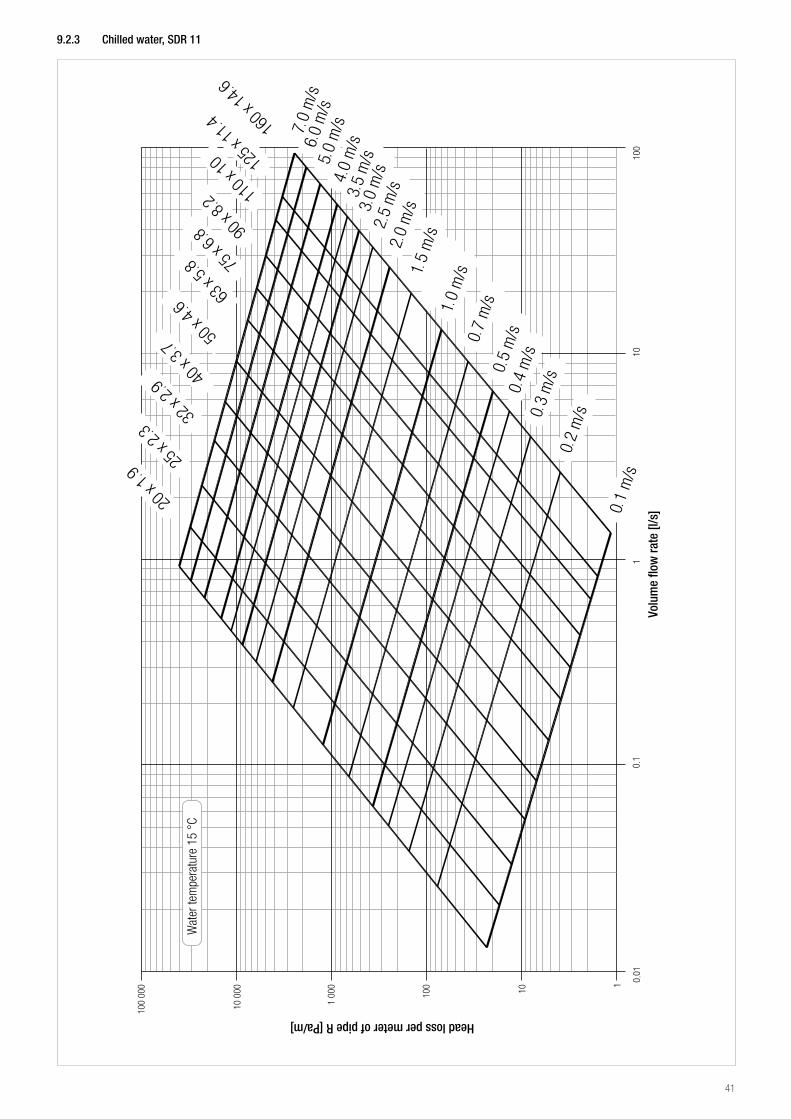
9 2 3 Chilled water, SDR 11
Head loss per meter of pipe R [Pa/m]
Volu
me
flow
rate
[l/s
]
Wat
er te
mpe
ratu
re 1
5 °C
41
9 2 4 Chilled water, SDR 7 4
Head loss per meter of pipe R [Pa/m]
Volu
me
flow
rate
[l/s
]
Wat
er te
mpe
ratu
re 1
5 °C
16 x
2.2
20 x
2.8
25 x
3.5
32 x
4.4
40 x
5.5
50 x
6.9
63 x
8.7
42
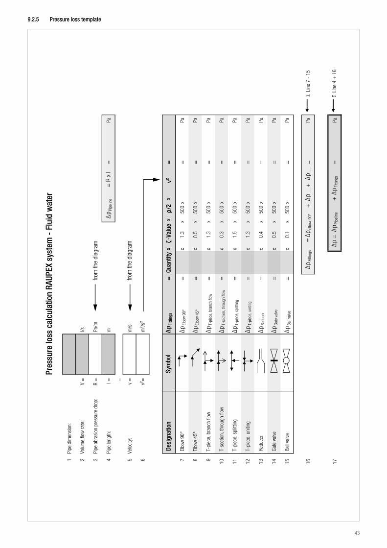
9 2 5 Pressure loss template
43
10 SOLID parTICLe TraNSpOrT
RAUPEX pipes are outstandingly well-suited to the transport of solids (refer to Sections 10.1 and 10.2 for exceptions).The high level of resistance provided by the RAU-PE-Xa material results in RAUPEX pipes providing significantly longer service life than steel or PE pipes when it comes to dealing with abrasive media.It should, however, be noted that directional changes must be made of curved RAUPEX pipe, since the highest abrasion values occur in the arc sections. We recommend the employment of electrofusion fittings for joints.
10 1 Hydraulic solids transportThe RAUPEX industrial piping systems has proven itself for applications involving the hydraulic transport of solid particles in water as the carrier medium.
If carrier media other than water are employed, the specific media resistance must not exceed 106 Ω x cm, otherwise electrostatic charges may be generated.
10 2 Pneumatic solids transportSince they do not conduct electricity, RAUPEX pipes are only applicable to pneumatic solids transport to a limited extent. As a result, electrostatic charges may be generated by the movement of air/particle mixtures.
The transport of certain air/particle mixtures may result in an explosion hazard due to electrostatic charges.
Charges can be avoided during air/particle mixture transport if the relative humidity is ≥ 65 %. In such situations, pneumatic solids transport is also permitted (refer also to the guidelines governing the prevention of risks due to electrostatic charges; published by the Chemical Industry Professional Association, Verlag Chemie GmbH, D-69469, Weinheim).
44
11 aSSeMbLY aND INSTaLLaTION
RAUPEX pipes can be installed openly in structures, under plaster, in cable ducts or in a cable carrier system. It may also be installed below the ground, in channels or in covered pipes.
Unwinding coilsWhen unwinding coils, always ensure that the pipe ends spring away when the connectors are released.Since large forces are released, particularly where larger coils are involved, appropriate care must be exercised.When trimming the pipes to size, ensure that no mechanical strain is exerted. Otherwise, each section being separated may require clamping since they may spring away. If the coils are stored in an upright position, they should be secured to prevent its falling over.Pipe stack height (for piece goods) should not exceed 1m. The pipes should be secured to prevent its rolling away to the side.
11 1 Subsoil installationBoth rigid as well as coiled RAUPEX pipes can be employed for subsoil installation, with pipe coils generally being more economical for longer stretches. Thanks to their material characteristics, RAUPEX pipes are ideal for subsoil installation. In particular trenchless installation techniques or installation outside sand beds make great demands on the raw material when it comes to notches, cracks and fast crack propagation. RAUPEX pipes are capable of meeting these demands as well.
For subsoil installation, compression sleeve fittings and compression sleeves must be sheathed with suitable jackets (e.g., sealing strips) to protect them from moisture, aggressive or corrosion-causing media and materials.
11 1 1 Subsoil workDuring subsoil and installation work, the requirements set forth in the DVGW regulation W400 must be complied with. The dimensioning of the pipe channel influences the size and distribution of the soil and traffic loads and, therefore, the loads on the pipeline. The width of the trench base depends on the external pipe diameter and whether minimum workspace in accordance with DIN 4124 is required. The trench base width and depth must be created so that the line rests upon it along its full length. The trench base must be dug at least 0.1 m deeper in stony or rocky soil, and the removed soil must be replaced with a layer free of stones. Where the trench base is non-bearing or watery, as well as where varying soil layers of different weight bearing ability alternate, the line must be secured by appropriate structural measures, e.g., by a fine gravel fill. Along graded sections, crossbeams must be provided to prevent the cover layer from being washed away. If necessary, drainage must be provided.
11 1 2 Pipe inspectionPrior to installation in the pipe trench, the pipes and pipe sections must be inspected for any shipping or storage faults in accordance with DVGW regulation W400-1. Pipes and pipe sections with sharp edged damage must not be installed. Grooves and scratches on pipes made of RAU-PE-Xa may not exceed 20 % of the pipe wall thickness.
11 1 3 Special considerations when working with coilsThere are several methods which can be employed to unwind pipes from coils. For pipes with an exterior diameter up to 63 mm, the coil is generally unrolled in an upright position.For larger pipe diameters, we recommend the employment of unwinding equipment.For example, the coils can be laid flat on turnstiles and the pipe can be uncoiled manually or by means of a slowly moving vehicle. Care must be taken to ensure that the uncoiled pipe length does not twist, as this can result in kinks.On request, coils can be coiled in layers at the factory. This will permit only the external layer to be unwound, once the ties have been released. The inner layers remain firmly in place. This will prevent the entire coil from opening up once the ties have been removed.The reduction in flexibility which occurs at low temperatures results in pipes being more difficult to unwind and install as the temperature approaches the freezing point. In this case, we recommend that the coils be stored in a heated hall or tent for several hours directly prior to installation. Alternatively, the pipes may also be warmed by passing hot air or steam at no more than 80°C through it.
11 1 4 Minimum deflection radii during subsoil installationFor subsoil installation of RAUPEX pipes, and depending on the installation temperature, the following minimum deflection radii must be observed:
Installation temperature Minimum deflection radius PE-Xa
20 °C 10 x d
10 °C 15 x d
0 °C 25 x d
d: Exterior pipe Ø
Tab. 31 Minimum deflection radius for subsoil installation
11 1 5 Backfilling the trenchShould direct sunlight result in the pipe temperature rising significantly above that of the pipe trench, the line should be lightly covered in order to avoid mechanical tension when the trench is backfilled.Deviating from DVGW regulation W400, removed soil can be employed to backfill the pipeline zone and the remaining pipe trench when the employed pipe is RAU-PE-Xa, provided that the following requirements are met: - The excavated soil must be readily compacted; - The maximum granulate size should not exceed 63 mm.
Scree material, recycled construction debris and ground tailings may also be employed in the pipeline zone. Backfilling of the remaining pipe trench in the road body area must conform to ZTV A-StB 97 “Additional Technical Contractual Terms and Guidelines for Excavating Traffic Areas”. Bearing the permissible backfill height in mind, mechanical equipment may be employed.
45
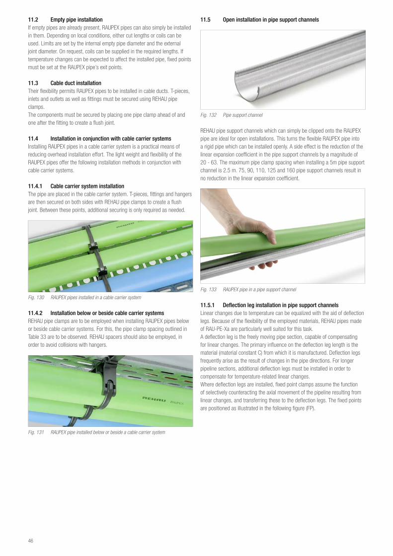
11 2 Empty pipe installationIf empty pipes are already present, RAUPEX pipes can also simply be installed in them. Depending on local conditions, either cut lengths or coils can be used. Limits are set by the internal empty pipe diameter and the external joint diameter. On request, coils can be supplied in the required lengths. If temperature changes can be expected to affect the installed pipe, fixed points must be set at the RAUPEX pipe’s exit points.
11 3 Cable duct installationTheir flexibility permits RAUPEX pipes to be installed in cable ducts. T-pieces, inlets and outlets as well as fittings must be secured using REHAU pipe clamps.The components must be secured by placing one pipe clamp ahead of and one after the fitting to create a flush joint.
11 4 Installation in conjunction with cable carrier systemsInstalling RAUPEX pipes in a cable carrier system is a practical means of reducing overhead installation effort. The light weight and flexibility of the RAUPEX pipes offer the following installation methods in conjunction with cable carrier systems.
11 4 1 Cable carrier system installationThe pipe are placed in the cable carrier system. T-pieces, fittings and hangers are then secured on both sides with REHAU pipe clamps to create a flush joint. Between these points, additional securing is only required as needed.
Fig. 130 RAUPEX pipes installed in a cable carrier system
11 4 2 Installation below or beside cable carrier systemsREHAU pipe clamps are to be employed when installing RAUPEX pipes below or beside cable carrier systems. For this, the pipe clamp spacing outlined in Table 33 are to be observed. REHAU spacers should also be employed, in order to avoid collisions with hangers.
Fig. 131 RAUPEX pipe installed below or beside a cable carrier system
11 5 Open installation in pipe support channels
Fig. 132 Pipe support channel
REHAU pipe support channels which can simply be clipped onto the RAUPEX pipe are ideal for open installations. This turns the flexible RAUPEX pipe into a rigid pipe which can be installed openly. A side effect is the reduction of the linear expansion coefficient in the pipe support channels by a magnitude of 20 - 63. The maximum pipe clamp spacing when installing a 5m pipe support channel is 2.5 m. 75, 90, 110, 125 and 160 pipe support channels result in no reduction in the linear expansion coefficient.
Fig. 133 RAUPEX pipe in a pipe support channel
11 5 1 Deflection leg installation in pipe support channelsLinear changes due to temperature can be equalized with the aid of deflection legs. Because of the flexibility of the employed materials, REHAU pipes made of RAU-PE-Xa are particularly well suited for this task.A deflection leg is the freely moving pipe section, capable of compensating for linear changes. The primary influence on the deflection leg length is the material (material constant C) from which it is manufactured. Deflection legs frequently arise as the result of changes in the pipe directions. For longer pipeline sections, additional deflection legs must be installed in order to compensate for temperature-related linear changes.Where deflection legs are installed, fixed point clamps assume the function of selectively counteracting the axial movement of the pipeline resulting from linear changes, and transferring these to the deflection legs. The fixed points are positioned as illustrated in the following figure (FP).
46
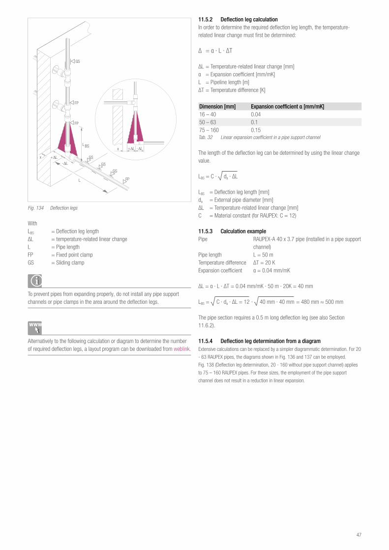
Fig. 134 Deflection legs
WithLBS = Deflection leg lengthΔL = temperature-related linear changeL = Pipe lengthFP = Fixed point clampGS = Sliding clamp
To prevent pipes from expanding properly, do not install any pipe support channels or pipe clamps in the area around the deflection legs.
Alternatively to the following calculation or diagram to determine the number of required deflection legs, a layout program can be downloaded from weblink.
11 5 2 Deflection leg calculationIn order to determine the required deflection leg length, the temperature-related linear change must first be determined:
Δ = α · L · ΔT
ΔL = Temperature-related linear change [mm]α = Expansion coefficient [mm/mK]L = Pipeline length [m]ΔT = Temperature difference [K]
Dimension [mm] Expansion coefficient α [mm/mK]16 – 40 0.0450 – 63 0.175 – 160 0.15Tab. 32 Linear expansion coefficient in a pipe support channel
The length of the deflection leg can be determined by using the linear change value.
LBS = C · √ da · ΔL
LBS = Deflection leg length [mm]da = External pipe diameter [mm]ΔL = Temperature-related linear change [mm]C = Material constant (for RAUPEX: C = 12)
11 5 3 Calculation examplePipe RAUPEX-A 40 x 3.7 pipe (installed in a pipe support channel)Pipe length L = 50 m Temperature difference ΔT = 20 KExpansion coefficient α = 0.04 mm/mK
ΔL = α · L · ΔT = 0.04 mm/mK · 50 m · 20K = 40 mm
LBS = √ C · da · ΔL = 12 · √ 40 mm · 40 mm = 480 mm ≈ 500 mm The pipe section requires a 0.5 m long deflection leg (see also Section 11.6.2).
11 5 4 Deflection leg determination from a diagramExtensive calculations can be replaced by a simpler diagrammatic determination. For 20
- 63 RAUPEX pipes, the diagrams shown in Fig. 136 and 137 can be employed.
Fig. 138 (Deflection leg determination, 20 - 160 without pipe support channel) applies
to 75 – 160 RAUPEX pipes. For these sizes, the employment of the pipe support
channel does not result in a reduction in linear expansion.
47
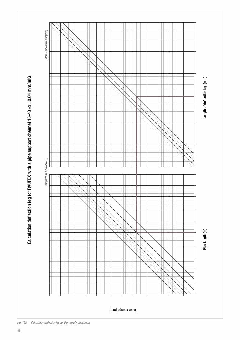
Calc
ulat
ion
defle
ctio
n le
g fo
r RAU
PEX
with
a p
ipe
supp
ort c
hann
el 1
6-40
(α =
0.04
mm
/mK)
Tem
pera
ture
di�
eren
ce [K
]Ex
tern
al p
ipe
diam
eter
[mm
]
Pipe
leng
th [m
]Le
ngth
of d
eflec
tion
leg
[mm
]
Linear change [mm]
Fig. 135 Calculation deflection leg for the sample calculation
48
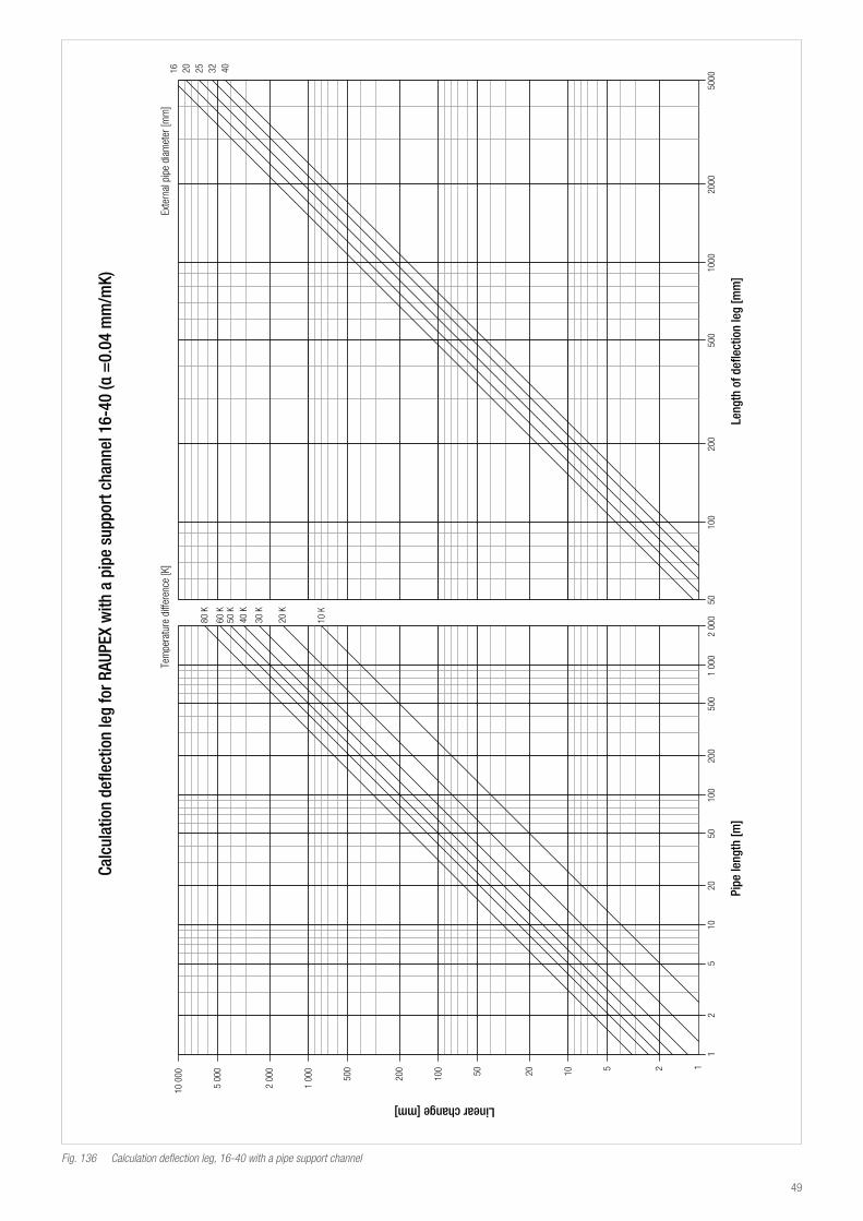
Calc
ulat
ion
defle
ctio
n le
g fo
r RAU
PEX
with
a p
ipe
supp
ort c
hann
el 1
6-40
(α =
0.04
mm
/mK)
Tem
pera
ture
di�
eren
ce [K
]Ex
tern
al p
ipe
diam
eter
[mm
]
Pipe
leng
th [m
]Le
ngth
of d
eflec
tion
leg
[mm
]
Linear change [mm]
Fig. 136 Calculation deflection leg, 16-40 with a pipe support channel
49
Pipe
leng
th [m
]Le
ngth
of d
eflec
tion
leg
[mm
]
Linear change [mm]
Tem
pera
ture
di�
eren
ce [K
]Ex
tern
al p
ipe
diam
eter
[mm
]50
63
Calc
ulat
ion
defle
ctio
n le
g fo
r RAU
PEX,
50-
63 w
ith a
pip
e su
ppor
t cha
nnel
Fig. 137 Calculation deflection leg, 50-63 with a pipe support channel
50
11 6 Surface mounted installation without pipe support channelsThis is the most common installation method inside buildings. RAUPEX pipes can also be installed in this way. Th specified maximum distances between pipe clips for this installation method are given below in table 33. depending on the ambient temperatures at time of installation.For this installation technique, the REHAU pipe clips are particularly advantageous, as they allow a quick and easy installation. It is important to install the pipes such that a temperature-related linear expansion can occur through the installation of deflection legs. - The given maximum spacings for clips can be increased by 30% when the pipe is installed vertically.
- For compressed air lines, the support spacings can also be increased by 30%
Dimension Support spacing [m]At 20 °C At 40 °C At 60 °C At 80 °C
20 0.60 0.55 0.45 0.4025 0.65 0.60 0.50 0.4532 0.75 0.65 0.60 0.5040 0.85 0.75 0.65 0.5550 0.95 0.85 0.75 0.6563 1.05 0.95 0.85 0.7075 1.15 1.05 0.90 0.7590 1.25 1.10 1.05 0.85110 1.40 1.25 1.10 0.95125 1.50 1.30 1.15 1.00160 1.70 1.40 1.30 1.10Medium density: 1 kg/dm³; Maximum sag 4 mmTab. 33 Support spacing for RAUPEX pipes without pipe support channel
11 6 1 Installation of deflection legsThe calculations according to 11.5.2 can be used to determine the required deflection legs. A linear expansion factor of α = 0.15 mm/mK must generally be used. Alternatively the chart method can also be used.
51
Pipe
leng
th [m
]Le
ngth
of d
eflec
tion
leg
[mm
]
Linear change [mm]
Tem
pera
ture
di�
eren
ce [K
]Ex
tern
al p
ipe
diam
eter
[mm
]
Calc
ulat
ion
defle
ctio
n le
g fo
r RAU
PEX
with
out a
pip
e su
ppor
t cha
nnel
16-
160
(α =
0.15
mm
/mK)
1620
2532
4050
6375
9012
5 160
110
Fig. 138 Calculation deflection leg, 16-160 without a pipe support channel
52
11 6 2 Pre-stressed installation techniqueAs an alternative to deflection legs, pipes can be pre-stressed during their installation. This method is particularly practical for long lengths of straight pipes or where there is no space for deflection legs. RAUPEX pipes are stretched to their anticipated maximum length and subsequently clamped into place. The fix points at the beginning and end of the pipe section must be sufficiently sturdy. The occurring forces to be absorbed by the fix points are given in Tables 34 and 35. After the pipe sections are stretched into place they do no longer expand or contract and temperature changes result in changing loads on the fix points.For compression sleeve joints, the tensioning equipment can be removed as soon as the joint has been completed. Electrofusion fittings and FUSAPEX electrofusion fittings must first cool down completely before the tension equipment can be removed(note the cool-down times). The following figures illustrate both the principle behind as well as a practical example of pre-stressed installation.
Installation length
expected length change during operation Safety
Fix point
Fitting
Draw pipe
Fig. 139 Principle of pre-stressed installation
Fig. 140 Tension equipment and fixed point design at Winkelmann GmbH + Co. KG
Δ T [K] 10 20 30 40 50 60 70 80 90 100Dimension [mm] F [N] F [N] F [N] F [N] F [N] F [N] F [N] F [N] F [N] F [N]20 x 1.9 117 233 350 467 583 700 817 933 1,050 1,16725 x 2.3 177 354 531 709 886 1,063 1,240 1,417 1,594 1,77132 x 2.9 286 573 859 1145 1,432 1,718 2,004 2,291 2,577 2,86340 x 3.7 456 911 1,367 1,823 2,279 2,734 3,190 3,646 4,101 4,55750 x 4.6 709 1,417 2,126 2,834 3,543 4,251 4,960 5,669 6,377 7,08663 x 5.8 1,126 2,251 3,377 4,503 5,628 6,754 7,879 9,005 10,131 11,25675 x 6.8 1,574 3,147 4,721 6,294 7,868 9,441 11,015 12,588 14,162 15,73590 x 8.2 2,276 4,552 6,828 9,103 11,379 13,655 15,931 18,207 20,483 22,758110 x 10 3,393 6,786 10,179 13,572 16,965 20,358 23,750 27,143 30,536 33,929125 x 11.4 4,394 8,788 13,182 17,576 21,970 26,364 30,758 35,152 39,546 43,940160 x 14.6 7,203 14,405 21,608 28,811 36,013 43,216 50,418 57,621 64,824 72,026Safety factor 1,2; Forces determined at 20 °C, The values deviate from the cited ones at different temperatures,Tab. 34 RAUPEX SDR 11 fixed point forces
Δ T [K] 10 20 30 40 50 60 70 80 90 100Dimension [mm] F [N] F [N] F [N] F [N] F [N] F [N] F [N] F [N] F [N] F [N]20 x 2.8 163 327 490 654 817 980 1,144 1,307 1,471 1,63425 x 3.5 255 511 766 1,021 1,277 1,532 1,787 2,043 2,298 2,55332 x 4.4 412 824 1,236 1,648 2,060 2,472 2,884 3,296 3,708 4,12040 x 5.5 644 1,288 1,931 2,575 3,219 3,863 4,507 5,150 5,794 6,43850 x 6.9 1,009 2,018 3,027 4,036 5,045 6,054 7,063 8,072 9,081 10,09063 x 8.7 1,603 3,206 4,809 6,411 8,014 9,617 11,220 12,823 14,426 16,028Safety factor 1.2; Forces determined at 20 °C. The values deviate from the cited ones at different temperatures.Tab. 35 RAUPEX SDR 7.4 fixed point forces
53
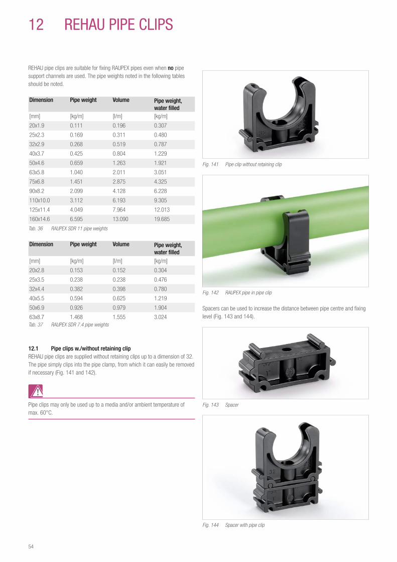
12 reHau pIpe CLIpS
REHAU pipe clips are suitable for fixing RAUPEX pipes even when no pipe support channels are used. The pipe weights noted in the following tables should be noted.
Dimension Pipe weight Volume Pipe weight, water filled
[mm] [kg/m] [l/m] [kg/m]
20x1.9 0.111 0.196 0.307
25x2.3 0.169 0.311 0.480
32x2.9 0.268 0.519 0.787
40x3.7 0.425 0.804 1.229
50x4.6 0.659 1.263 1.921
63x5.8 1.040 2.011 3.051
75x6.8 1.451 2.875 4.325
90x8.2 2.099 4.128 6.228
110x10.0 3.112 6.193 9.305
125x11.4 4.049 7.964 12.013
160x14.6 6.595 13.090 19.685
Tab. 36 RAUPEX SDR 11 pipe weights
Dimension Pipe weight Volume Pipe weight, water filled
[mm] [kg/m] [l/m] [kg/m]
20x2.8 0.153 0.152 0.304
25x3.5 0.238 0.238 0.476
32x4.4 0.382 0.398 0.780
40x5.5 0.594 0.625 1.219
50x6.9 0.926 0.979 1.904
63x8.7 1.468 1.555 3.024Tab. 37 RAUPEX SDR 7.4 pipe weights
12 1 Pipe clips w /without retaining clipREHAU pipe clips are supplied without retaining clips up to a dimension of 32. The pipe simply clips into the pipe clamp, from which it can easily be removed if necessary (Fig. 141 and 142).
Pipe clips may only be used up to a media and/or ambient temperature of max. 60°C.
Fig. 141 Pipe clip without retaining clip
Fig. 142 RAUPEX pipe in pipe clip
Spacers can be used to increase the distance between pipe centre and fixing level (Fig. 143 and 144).
Fig. 143 Spacer
Fig. 144 Spacer with pipe clip
54
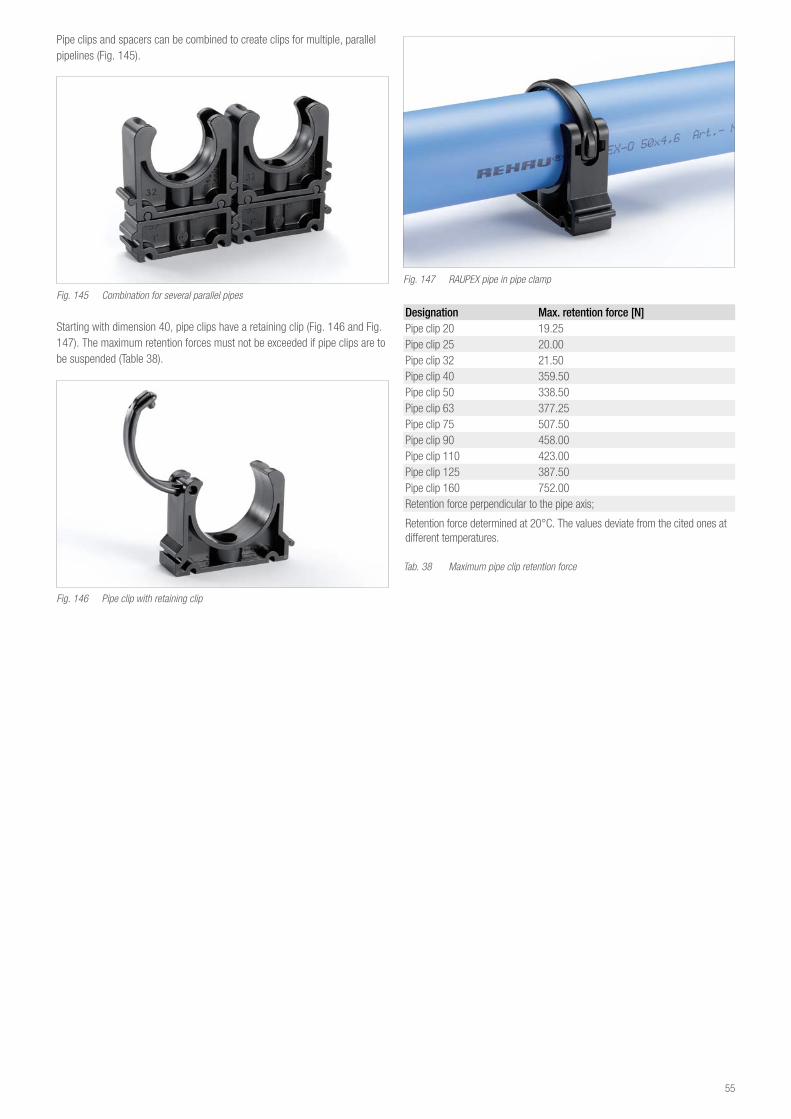
Pipe clips and spacers can be combined to create clips for multiple, parallel pipelines (Fig. 145).
Fig. 145 Combination for several parallel pipes
Starting with dimension 40, pipe clips have a retaining clip (Fig. 146 and Fig. 147). The maximum retention forces must not be exceeded if pipe clips are to be suspended (Table 38).
Fig. 146 Pipe clip with retaining clip
Fig. 147 RAUPEX pipe in pipe clamp
Designation Max retention force [N]Pipe clip 20 19.25Pipe clip 25 20.00Pipe clip 32 21.50Pipe clip 40 359.50Pipe clip 50 338.50Pipe clip 63 377.25Pipe clip 75 507.50Pipe clip 90 458.00Pipe clip 110 423.00Pipe clip 125 387.50Pipe clip 160 752.00Retention force perpendicular to the pipe axis;
Retention force determined at 20°C. The values deviate from the cited ones at different temperatures.
Tab. 38 Maximum pipe clip retention force
55
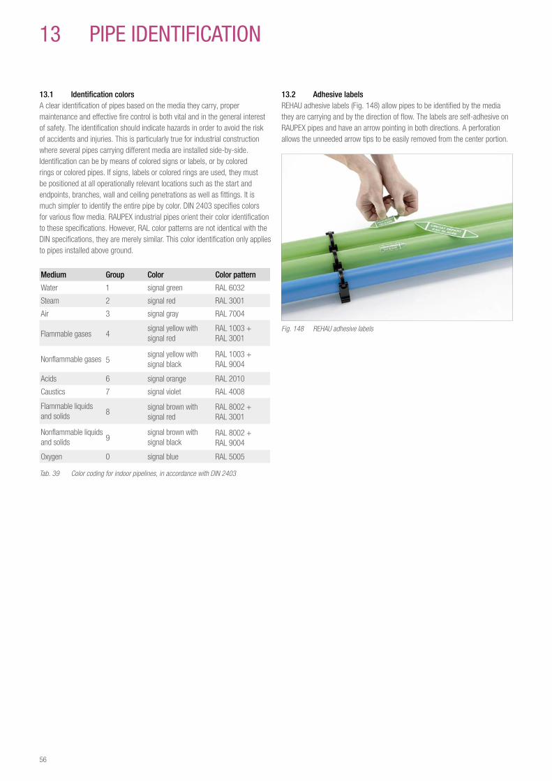
13 1 Identification colorsA clear identification of pipes based on the media they carry, proper maintenance and effective fire control is both vital and in the general interest of safety. The identification should indicate hazards in order to avoid the risk of accidents and injuries. This is particularly true for industrial construction where several pipes carrying different media are installed side-by-side. Identification can be by means of colored signs or labels, or by colored rings or colored pipes. If signs, labels or colored rings are used, they must be positioned at all operationally relevant locations such as the start and endpoints, branches, wall and ceiling penetrations as well as fittings. It is much simpler to identify the entire pipe by color. DIN 2403 specifies colors for various flow media. RAUPEX industrial pipes orient their color identification to these specifications. However, RAL color patterns are not identical with the DIN specifications, they are merely similar. This color identification only applies to pipes installed above ground.
Medium Group Color Color pattern
Water 1 signal green RAL 6032
Steam 2 signal red RAL 3001
Air 3 signal gray RAL 7004
Flammable gases 4signal yellow with signal red
RAL 1003 +RAL 3001
Nonflammable gases 5signal yellow with signal black
RAL 1003 +RAL 9004
Acids 6 signal orange RAL 2010
Caustics 7 signal violet RAL 4008
Flammable liquids and solids 8
signal brown withsignal red
RAL 8002 +RAL 3001
Nonflammable liquids and solids 9
signal brown withsignal black
RAL 8002 +RAL 9004
Oxygen 0 signal blue RAL 5005
Tab. 39 Color coding for indoor pipelines, in accordance with DIN 2403
13 pIpe IDeNTIFICaTION
13 2 Adhesive labelsREHAU adhesive labels (Fig. 148) allow pipes to be identified by the media they are carrying and by the direction of flow. The labels are self-adhesive on RAUPEX pipes and have an arrow pointing in both directions. A perforation allows the unneeded arrow tips to be easily removed from the center portion.
Fig. 148 REHAU adhesive labels
56
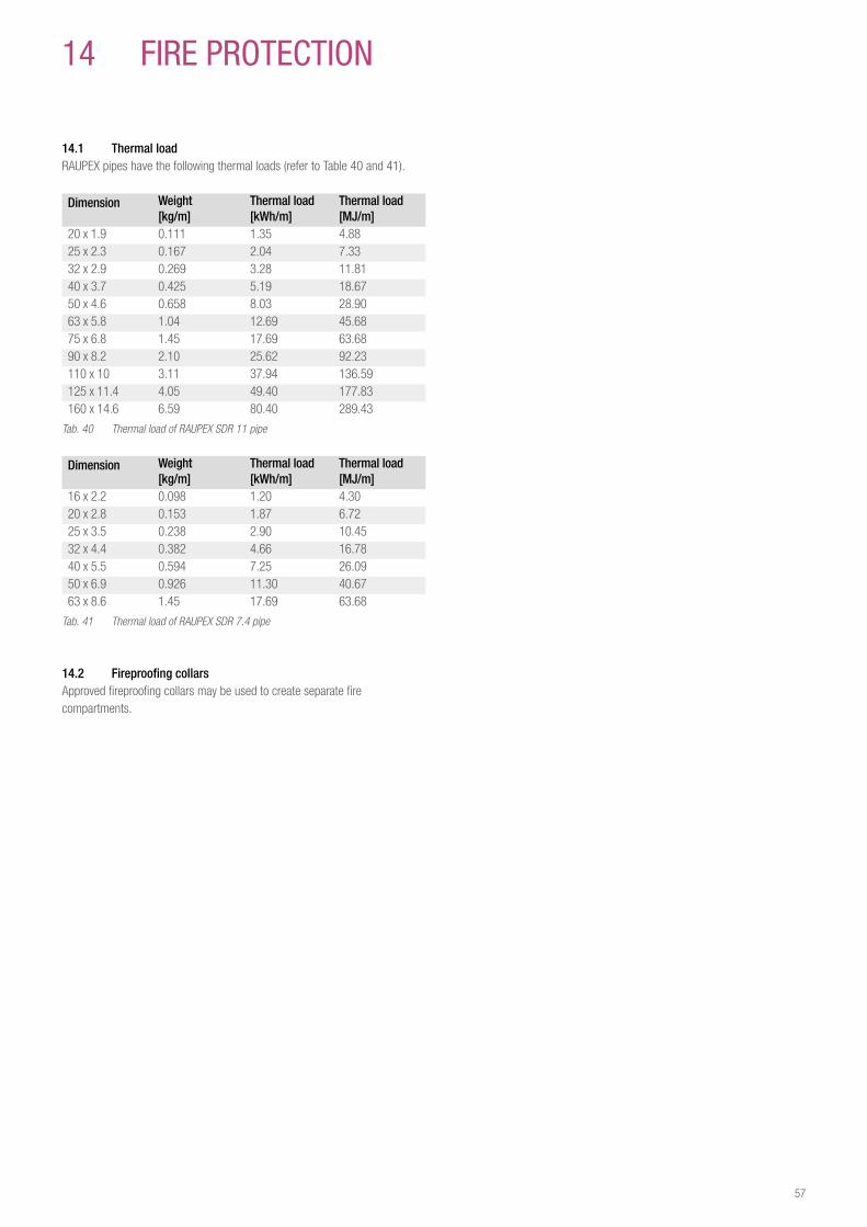
14 FIre prOTeCTION
14 1 Thermal loadRAUPEX pipes have the following thermal loads (refer to Table 40 and 41).
Dimension Weight [kg/m]
Thermal load [kWh/m]
Thermal load[MJ/m]
20 x 1.9 0.111 1.35 4.8825 x 2.3 0.167 2.04 7.3332 x 2.9 0.269 3.28 11.8140 x 3.7 0.425 5.19 18.6750 x 4.6 0.658 8.03 28.9063 x 5.8 1.04 12.69 45.6875 x 6.8 1.45 17.69 63.6890 x 8.2 2.10 25.62 92.23110 x 10 3.11 37.94 136.59125 x 11.4 4.05 49.40 177.83160 x 14.6 6.59 80.40 289.43
Tab. 40 Thermal load of RAUPEX SDR 11 pipe
Dimension Weight [kg/m]
Thermal load [kWh/m]
Thermal load[MJ/m]
16 x 2.2 0.098 1.20 4.3020 x 2.8 0.153 1.87 6.7225 x 3.5 0.238 2.90 10.4532 x 4.4 0.382 4.66 16.7840 x 5.5 0.594 7.25 26.0950 x 6.9 0.926 11.30 40.6763 x 8.6 1.45 17.69 63.68
Tab. 41 Thermal load of RAUPEX SDR 7.4 pipe
14 2 Fireproofing collarsApproved fireproofing collars may be used to create separate fire compartments.
57
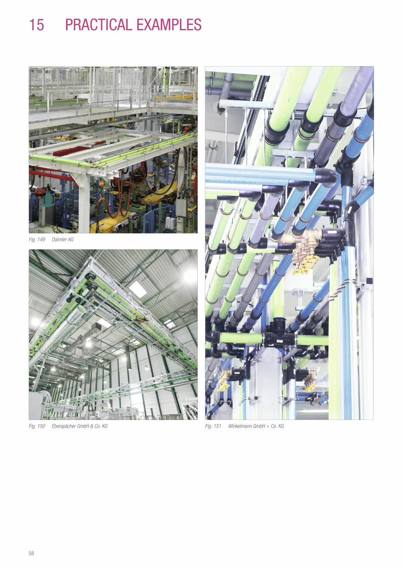
15 praCTICaL exaMpLeS
Fig. 149 Daimler AG
Fig. 150 Eberspächer GmbH & Co. KG Fig. 151 Winkelmann GmbH + Co. KG
58
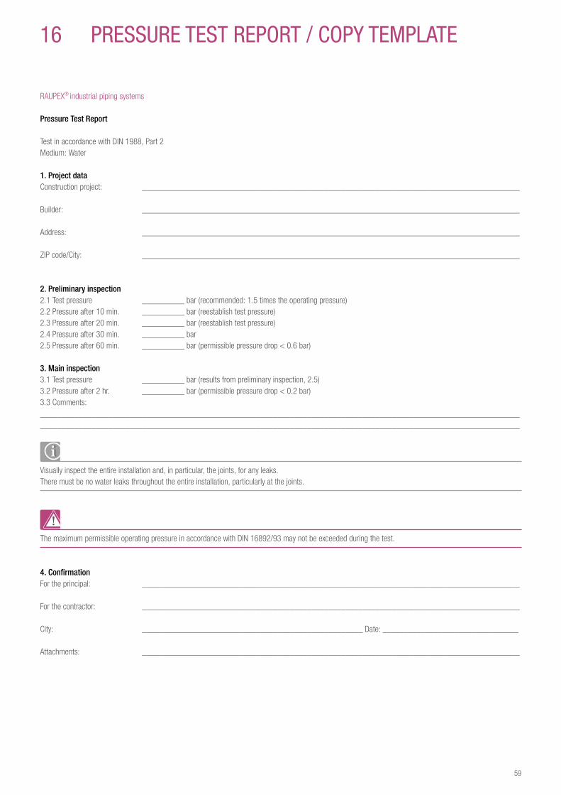
16 preSSure TeST repOrT / COpY TeMpLaTe
RAUPEX® industrial piping systems
Pressure Test Report
Test in accordance with DIN 1988, Part 2Medium: Water
1 Project dataConstruction project: _________________________________________________________________________________________
Builder: _________________________________________________________________________________________
Address: _________________________________________________________________________________________
ZIP code/City: _________________________________________________________________________________________
2 Preliminary inspection2.1 Test pressure __________ bar (recommended: 1.5 times the operating pressure)2.2 Pressure after 10 min. __________ bar (reestablish test pressure)2.3 Pressure after 20 min. __________ bar (reestablish test pressure)2.4 Pressure after 30 min. __________ bar2.5 Pressure after 60 min. __________ bar (permissible pressure drop < 0.6 bar)
3 Main inspection3.1 Test pressure __________ bar (results from preliminary inspection, 2.5)3.2 Pressure after 2 hr. __________ bar (permissible pressure drop < 0.2 bar)3.3 Comments:__________________________________________________________________________________________________________________________________________________________________________________________________________________________________
Visually inspect the entire installation and, in particular, the joints, for any leaks.There must be no water leaks throughout the entire installation, particularly at the joints.
The maximum permissible operating pressure in accordance with DIN 16892/93 may not be exceeded during the test.
4 ConfirmationFor the principal: _________________________________________________________________________________________
For the contractor: _________________________________________________________________________________________
City: ____________________________________________________ Date: ________________________________
Attachments: _________________________________________________________________________________________
59

17 STaNDarDS, reguLaTIONS, DIreCTIVeS
In addition to the information provided in this Technical Information, please also observe all national and international regulations governing installation, accident prevention and general safety when installing the pipeline.
Also please comply with all applicable codes, standards, directives, regulations (e.g., DIN, EN, ISO, DVGW, TRGI, VDE and VDI), together with regulations related to environmental protection, professional association guidelines and local public utility regulations.
Any applications not discussed in this Technical Information (special applications) require consultation with our Application Technology Department. For more detailed help, please contact your local REHAU Sales Office.
The planning and installation instructions are directly linked to the individual REHAU product. Excerpts related to generally applicable standards and directives will be made.
Please always note the most current, valid version of the directives, standards and regulations.
Additional standards, regulations and directives related to planning, installation and operation of the construction and industrial technology equipment must also be taken into account, even though they do not form an integral part of this Technical Information.
DIN 2403Pipeline Identification Based on the Media Being Carried
DIN 4124Building Excavations and Trenches; Embankments, Shoring, Workplace Widths
DIN 4726Pipelines Made of Plastic; Warm Water Subsurface Heating and Radiator Connections
DIN 8075Pipelines Made of Polyethylene (PE) - PE 63, PE 80, PE 100, PE-HD; General Quality Requirements, Testing
DIN 16892Pipelines Made of High-density, Cross-linked Polyethylene (PE-X); General Quality Requirements, Testing
Revision 1Revisions to DIN 16892
DIN 16893Pipelines Made of High-density, Cross-linked Polyethylene (PE-X); Dimensions, Testing
Revision 1Revisions to DIN 16893
DIN EN 10204Metal Components; Types of Test Certifications
DIN EN 12164Copper and Copper Alloys; Bars for Machining
DIN EN 12165Copper and Copper Alloys; Preliminary Material for Forging
DIN EN 12168Copper and Copper Alloys; Hollow Bars for Machining
DIN EN ISO 1133Plastics; Determination of the Melt Flow Rate (MFR) and the Melt Volume Rate (MVR) for Thermoplastics
DIN EN ISO 1183Plastics; Process to Determine the Density of Unexpanded Plastics
ISO 8573-1Compressed air; Contaminants and Purity Classes
VDMA 15390Compressed Air Quality; List of Recommended Purity Classes in Accordance with ISO 8573-1
DVGW W 400Technical Rules Governing Water Distribution Equipment
ZTV A-StB 97Additional Technical Contract Terms and Guidelines for Excavating Traffic Areas
60

61
NOTeS

62
NOTeS

63
NOTeS
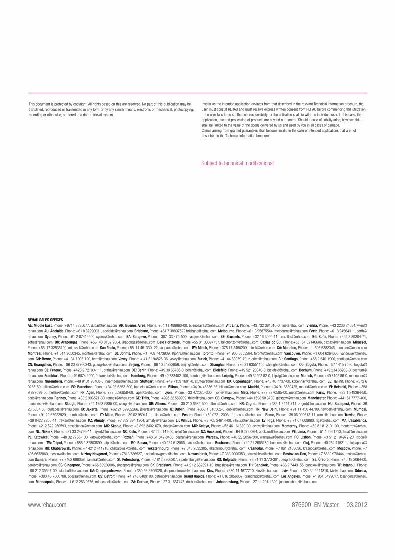
REHAU SALES OFFICES AE: Middle East, Phone: +9714 8835677, [email protected] AR: Buenos Aires, Phone: +54 11 489860-00, [email protected] AT: Linz, Phone: +43 732 381610-0, [email protected] Vienna, Phone: +43 2236 24684, [email protected] AU: Adelaide, Phone: +61 8 82990031, [email protected] Brisbane, Phone: +61 7 38897522 [email protected] Melbourne, Phone: +61 3 95875544, [email protected] Perth, Phone: +61 8 94564311, [email protected] Sydney, Phone: +61 2 87414500, [email protected] BA: Sarajevo, Phone: +387 33 475-500, [email protected] BE: Brussels, Phone: +32 16 3999-11, [email protected] BG: Sofia, Phone: +359 2 89204-71, [email protected] BR: Arapongas, Phone: +55 43 3152 2004, [email protected] Belo Horizonte, Phone:+55 31 33097737, [email protected] Caxias do Sul, Phone:+55 54 32146606, [email protected] Mirassol, Phone: +55 17 32535190, [email protected] Sao Paulo, Phone: +55 11 461339- 22, [email protected] BY: Minsk, Phone: +375 17 2450209, [email protected] CA: Moncton, Phone: +1 506 5382346, [email protected] Montreal, Phone: +1 514 9050345, [email protected] St. John‘s, Phone: +1 709 7473909, [email protected] Toronto, Phone: +1 905 3353284, [email protected] Vancouver, Phone: +1 604 6264666, [email protected] CH: Berne, Phone: +41 31 7202-120, [email protected] Vevey, Phone: + 41 21 94826-36, [email protected] Zurich, Phone: +41 44 83979-79, [email protected] CL: Santiago, Phone: +56 2 540-1900, [email protected] CN: Guangzhou, Phone: +86 20 87760343, [email protected] Beijing, Phone: +86 10 64282956, [email protected] Shanghai, Phone: +86 21 63551155, [email protected] CO: Bogota, Phone: +57 1415 7590, [email protected] CZ: Prague, Phone: +420 2 72190-111, [email protected] DE: Berlin, Phone: +49 30 66766-0, [email protected] Bielefeld, Phone: +49 521 20840-0, [email protected] Bochum, Phone: +49 234 68903-0, [email protected] Frankfurt, Phone: +49 6074 4090-0, [email protected] Hamburg, Phone: +49 40 733402-100, [email protected] Leipzig, Phone: +49 34292 82-0, [email protected] Munich, Phone: +49 8102 86-0, [email protected] Nuremberg, Phone: +49 9131 93408-0, [email protected] Stuttgart, Phone: +49 7159 1601-0, [email protected] DK: Copenhagen, Phone: +45 46 7737-00, [email protected] EE: Tallinn, Phone: +372 6 0258-50, [email protected] ES: Barcelona, Phone: +34 93 6353-500, [email protected] Bilbao, Phone: +34 94 45386-36, [email protected] Madrid, Phone: +34 91 6839425, [email protected] FI: Helsinki, Phone: +358 9 877099-00, [email protected] FR: Agen, Phone: +33 5536958-69, [email protected] Lyon, Phone: +33 472026-300, [email protected] Metz, Phone: +33 3870585-00, [email protected] Paris, Phone: +33 1 348364-50, [email protected] Rennes, Phone: +33 2 996521-30, [email protected] GE: Tiflis, Phone: +995 32 559909, [email protected] GB: Glasgow, Phone: +44 1698 50 3700, [email protected] Manchester, Phone: +44 161 7777-400, [email protected] Slough, Phone: +44 1753 5885-00, [email protected] GR: Athens, Phone: +30 210 6682-500, [email protected] HR: Zagreb, Phone: +385 1 3444-711, [email protected] HU: Budapest, Phone:+36 23 5307-00, [email protected] ID: Jakarta, Phone: +62 21 89902266, [email protected] IE: Dublin, Phone: +353 1 816502-0, [email protected] IN: New Delhi, Phone: +91 11 450 44700, [email protected] Mumbai, Phone: +91 22 67922929, [email protected] IT: Milan, Phone: +39 02 95941-1, [email protected] Pesaro, Phone: +39 0721 2006-11, [email protected] Rome, Phone: +39 06 900613-11, [email protected] Treviso, Phone: +39 0422 7265-11, [email protected] KZ: Almaty, Phone: +7 727 394 1304, [email protected] LT: Vilnius, Phone: +3 705 24614-00, [email protected] LV: Riga, Phone: +3 71 67 609080, [email protected] MA: Casablanca, Phone: +212 522 250593, [email protected] MK: Skopje, Phone: +3 892 2402-670, [email protected] MX: Celaya, Phone: +52 461 61880-00, [email protected] Monterrey, Phone: +52 81 81210-130, [email protected] NL: Nijkerk, Phone: +31 33 24799-11, [email protected] NO: Oslo, Phone: +47 22 5141-50, [email protected] NZ: Auckland, Phone: +64 9 2722264, [email protected] PE: Lima, Phone: +51 1 2261713, [email protected] PL: Katowice, Phone: +48 32 7755-100, [email protected] Poznań, Phone: +48 61 849-8400, [email protected] Warsaw, Phone: +48 22 2056-300, [email protected] PO: Lisbon, Phone: +3 51 21 94972-20, [email protected] TW: Taipei, Phone: +886 2 87803899, [email protected] RO: Bacau, Phone: +40 234 512066, [email protected] Bucharest, Phone: +40 21 2665180, [email protected] Cluj, Phone: +40 264 415211, [email protected] RU: Chabarowsk, Phone: +7 4212 411218, [email protected] Yekaterinburg, Phone: +7 343 2535305, [email protected] Krasnodar, Phone: +7 861 2103636, [email protected] Moscow, Phone: +7 495 6632060, [email protected] Nizhny Novgorod, Phone: +7813 786927, [email protected] Nowosibirsk, Phone: +7 383 2000353, [email protected] Rostov-on-Don, Phone: +7 8632 978444, [email protected] Samara, Phone: +7 8462 698058, [email protected] St. Petersburg, Phone: +7 812 3266207, [email protected] RS: Belgrade, Phone: +3 81 11 3770-301, [email protected] SE: Örebro, Phone: +46 19 2064-00, [email protected] SG: Singapore, Phone: +65 63926006, [email protected] SK: Bratislava, Phone: +4 21 2 682091-10, [email protected] TH: Bangkok, Phone: +66 2 7443155, [email protected] TR: Istanbul, Phone: +90 212 35547-00, [email protected] UA: Dnepropetrowsk, Phone: +380 56 3705028, [email protected] Kiev, Phone: +380 44 4677710, [email protected] Lviv, Phone: +380 32 2244810, [email protected] Odessa, Phone: +380 48 7800708, [email protected] US: Detroit, Phone: +1 248 8489100, [email protected] Grand Rapids, Phone: +1 616 2856867, [email protected] Los Angeles, Phone: +1 951 5499017, [email protected] Minneapolis, Phone: +1 612 253 0576, [email protected] ZA: Durban, Phone: +27 31 657447, [email protected] Johannesburg, Phone: +27 11 201-1300, [email protected]
Insofar as the intended application deviates from that described in the relevant Technical Information brochure, theuser must consult REHAU and must receive express written consent from REHAU before commencing this utilization.If the user fails to do so, the sole responsibility for the utilization shall lie with the individual user. In this case, theapplication, use and processing of products are beyond our control. Should a case of liability arise, however, thisshall be limited to the value of the goods delivered by us and used by you in all cases of damage.Claims arising from granted guarantees shall become invalid in the case of intended applications that are not described in the Technical Information brochures.
Englisch HIS TI Prospekt
This document is protected by copyright. All rights based on this are reserved. No part of this publication may betranslated, reproduced or transmitted in any form or by any similar means, electronic or mechanical, photocopying,recording or otherwise, or stored in a data retrieval system.
Urheberrecht Englisch
Subject to technical modifications!
www.rehau.com 876600 EN Master 03.2012


